

Matrix MTX-ROUTER GPRS, MTX-ROUTER CDMA, MTX-ROUTER 3G, MTX-ROUTER 3G WIFI, MTX-ROUTER LTE WIFI User Manual
Page 1

MTX-Router Series
User Manual
Documentation No. Product Version Page
A
Product Name:
Router
Total:
MTX-ROUTER Series User Manual
The user manual is suitable for the following model:
Model Product Type
MTX-ROUTER GPRS GPRS ROUTER
MTX-ROUTER CDMA CDMA ROUTER
MTX-ROUTER 3G HSPA ROUTER
MTX-ROUTER 3G WIFI HSPA WIFI ROUTER
MTX-ROUTER LTE WIFI LTE/WCDMA WIFI ROUTER
Matrix Electroncia S.L
C/Alejandro Sánchez 109.
28019 Madrid. ESPAÑA - SPAIN
Teléfono/Phone: 902.19.81.46 / +34-91.560.27.37
Fax: 902.99.54.14 / +34-91.565.28.65
http://www.matrix.es
Page 2

MTX-ROUTER User Manual
Matrix Electronica S.L Page 2 of 87
Add: Alejandro Sanchez 109, 28019 Ma dr id. ESPAÑA
http://www.mtx-terminals.com Tel:+34-91.560.27.37 Fax:+34+34-91.565.28.65
Page 3

MTX-ROUTER User Manual
Matrix Electronica S.L Page 3 of 87
Add: Alejandro Sanchez 109, 28019 Ma dr id. ESPAÑA
http://www.mtx-terminals.com Tel:+34-91.560.27.37 Fax:+34+34-91.565.28.65
Files Revised Record
Date Version Remark Author
2012-09-16 V1.00 Initial Draft ZYL
2012-11-1 V1.01 Add Packet Filter PF
Page 4

MTX-ROUTER User Manual
Matrix Electronica S.L Page 4 of 87
Add: Alejandro Sanchez 109, 28019 Ma dr id. ESPAÑA
http://www.mtx-terminals.com Tel:+34-91.560.27.37 Fax:+34+34-91.565.28.65
Copyright Notice
All contents in the files are protected by copyright law, and all copyrights are reserved by Matrix
Electrónica S.L. Without written permission, all commercial use of the files from Matrix are
forbidden, such as copy, distribute, reproduce the files, etc., but non-commercial purpose,
downloaded or printed by individual (all files shall be not revised, and the copyright and other
proprietorship notice shall be reserved) are welcome.
Trademark Notice
MTX-ROUTER, MTX TERMINALS are all registered trademarks of Matrix Electrónica., illega l
use of the name of MTX-ROUTER, trademarks and other marks of Matrix is forbidden, unless
written permission is authorized in advance.
Page 5
MTX-ROUTER User Manual
Matrix Electronica S.L Page 5 of 87
Add: Alejandro Sanchez 109, 28019 Ma dr id. ESPAÑA
http://www.mtx-terminals.com Tel:+34-91.560.27.37 Fax:+34+34-91.565.28.65
Page 6

MTX-ROUTER User Manual
Matrix Electronica S.L Page 6 of 87
Add: Alejandro Sanchez 109, 28019 Ma dr id. ESPAÑA
http://www.mtx-terminals.com Tel:+34-91.560.27.37 Fax:+34+34-91.565.28.65
CCoonntteennttss
Chapter 1 Brief Introduction of Product ........................................................................................... 8
1.1 General ............................................................................................................................. 8
1.2 Features and Benefits ....................................................................................................... 8
1.3 W orking Princi ple .......................................................................................................... 10
1.4 Specifications ................................................................................................................. 10
Chapter 2 Installation Introduction ................................................................................................. 13
2.1 General ........................................................................................................................... 13
2.2 Encasement List ............................................................................................................. 13
2.3 Installation and Cable Connection ................................................................................. 13
2.4 Power ............................................................................................................................. 15
2.5 Indicator Lights Introduction ......................................................................................... 15
2.6 Reset Button Introduction .............................................................................................. 16
Chapter 3 Configuration and Management ..................................................................................... 16
3.1 Configuration Connection .............................................................................................. 17
3.2 Access the Configuration Web Page .............................................................................. 17
3.3 Management and configuration ..................................................................................... 19
3.3.1 Setting ........................................................................................................... 19
3.3.1.1 Basic Setting ............................................................................................ 19
3.3.1.2 Dynamic DNS ......................................................................................... 24
3.3.1.3 Clone MAC Address ............................................................................... 25
3.3.1.4 Advanced Router ..................................................................................... 25
3.3.1.5 Networking .............................................................................................. 26
3.3.2 Wireless ......................................................................................................... 29
3.3.2.1 Basic Settings .......................................................................................... 29
3.3.2.2 Wireless Security ..................................................................................... 31
3.3.2.3 Wireless MAC Filter ............................................................................... 34
3.3.2.4 Advance Settings ..................................................................................... 35
3.3.2.5 WDS ........................................................................................................ 39
3.3.3 Services ......................................................................................................... 41
3.3.3.1 Services ................................................................................................... 41
3.3.3.2 PPPoE Server .......................................................................................... 44
3.3.4 VPN ................................................................................................................... 46
3.3.4.1 PPTP ........................................................................................................ 46
3.3.4.2 L2TP ........................................................................................................ 47
3.3.4.3 OPENVPN .............................................................................................. 48
3.3.4.4 IPSEC ...................................................................................................... 53
3.3.4.5 GRE ......................................................................................................... 55
3.3.5 Security ......................................................................................................... 56
3.3.5.1 Firewall ................................................................................................... 56
3.3.5.2 VPN Passthrough .................................................................................... 59
Page 7

MTX-ROUTER User Manual
Matrix Electronica S.L Page 7 of 87
Add: Alejandro Sanchez 109, 28019 Ma dr id. ESPAÑA
http://www.mtx-terminals.com Tel:+34-91.560.27.37 Fax:+34+34-91.565.28.65
3.3.6 Access Restrictions ................................................................................... 60
3.3.6.1 WAN Access ............................................................................................ 60
3.3.6.2 Packet Filter ............................................................................................ 62
3.3.7 NAT ................................................................................................................... 63
3.3.7.1 Port Forwarding ...................................................................................... 63
3.3.7.2 Port Range Forward ................................................................................ 64
3.3.7.3 Port Triggering ........................................................................................ 64
3.3.7.4 DMZ ........................................................................................................ 65
3.3.8 QoS Setting ................................................................................................... 66
3.3.8.1 Basic ........................................................................................................ 66
3.3.8.2 Classify .................................................................................................... 66
3.3.9 Applications ................................................................................................. 67
3.3.9.1 Serial Applications .................................................................................. 67
3.3.10 Administration ..................................................................................... 68
3.3.10.1 Management .................................................................................... 68
3.3.10.2 Keep Alive ....................................................................................... 70
3.3.10.3 Commands ....................................................................................... 71
3.3.10.4 Factory Defaults .............................................................................. 71
3.3.10.5 Firmware Upgrade ........................................................................... 72
3.3.10.6 Backup ............................................................................................. 72
3.3.11 Status ..................................................................................................... 73
3.3.11.1 Router .............................................................................................. 73
3.3.11.2 WAN ................................................................................................ 75
3.3.11.3 LAN................................................................................................. 77
3.3.11.4 Wireless ........................................................................................... 80
3.3.11.5 Bandwidth ....................................................................................... 81
3.3.11.6 Sys-Info ........................................................................................... 83
Chapter 4 Appendix ........................................................................................................................ 86
Page 8
MTX-ROUTER User Manual
Matrix Electronica S.L Page 8 of 87
Add: Alejandro Sanchez 109, 28019 Ma dr id. ESPAÑA
http://www.mtx-terminals.com Tel:+34-91.560.27.37 Fax:+34+34-91.565.28.65
Chapter 1 Brief Introduction of Product
1.1 General
MTX-ROUTER series is a kind of cellular terminal device that provides data transfer
function by public cellular network.
It adopts high-powered industrial 32-bits CPU and embedded real time operating system. It
supports RS232 (or RS485/RS422), Ethernet and WIFI port that can conveniently and
transparently connect one device to a cellular network, allowing you to connect to your existing
serial, Ethernet and WIFI devices with only basic configuration.
It has been widely used on M2M fields, such as intelligent transportation, smart grid,
industrial automation, telemetry, finance, POS, water supply, environment protection, post,
weather, and so on.
1.2 Features and Benefits
Design for Industrial Application
High-powered industrial cellular module
High-powered industrial 32bits CPU
Support low-consumption mode, including sleep mode, s chedul ed onli ne/offline mode,
scheduled power-on/power-off mode(optional)
Housing: iron, providing IP30 protection.
Power range: DC 5~35V
Stability and Reliability
Support hardware and software WD T
Support auto recovery mechanism, including online detect, auto redial when offline to make
router always online
Ethernet port: 1.5KV magnetic isolation protection
RS232/RS485/RS422 port: 15KV ESD protection
SIM/UIM port: 15KV ESD protection
Power port: reverse-voltage and overvoltage protection
Page 9

MTX-ROUTER User Manual
Matrix Electronica S.L Page 9 of 87
Add: Alejandro Sanchez 109, 28019 Ma dr id. ESPAÑA
http://www.mtx-terminals.com Tel:+34-91.560.27.37 Fax:+34+34-91.565.28.65
Antenna port: lightning protection(optional)
Standard and Convenience
Support standard RS232(or RS485/RS422), Ethernet and WIFI port that can connect to serial,
Ethernet and WIFI devices directly
Support intellectual mode, enter into communication state automatically when powered
Provide management software for remote management
Support several work modes
Convenient configuration and maintenance interface(WEB or CLI)
High-performance
Support 3G/HSPA/4G WAN access methods.
Support VPN client(PPTP, L2TP, OPENVPN, IPSEC and GRE)(only for VPN version)
Support VPN server(PPTP, L2TP, OPENVPN, IPSEC and GRE)(only for VPN version)
Support local and remote firmware upgrade,import and export configure file.
Support NTP, RTC embedded.
Support mulitiple DDNS provider service.
Support MAC Address clone, PPPoE Server
WIFI support 802.11b/g/n. support AP, client, Adhoc, Repeater, Repeater Bridge and
WDS(optional) mode.
WIFI support WEP,WPA ,WPA2 encryption,Support RADIUS authentication and MAC
address filter.
Support multi online trigger ways, including SMS, ring and data. Support link disconnection
when timeout
Support APN/VPDN
Support DHCP server and client, firewall, NAT, DMZ host , URL block, QoS, ttraff,statistics,
real time link speed statistics etc.
Full protocol support , such as TCP/IP, UDP, ICMP, SMTP, HTTP, POP3, OICQ, TELNET,
FTP, SNMP, SSHD, etc.
Schedule Reboot, Schedule Online and Off li ne,etc.
Page 10
MTX-ROUTER User Manual
Matrix Electronica S.L Page 10 of 87
Add: Alejandro Sanchez 109, 28019 Ma dr id. ESPAÑA
http://www.mtx-terminals.com Tel:+34-91.560.27.37 Fax:+34+34-91.565.28.65
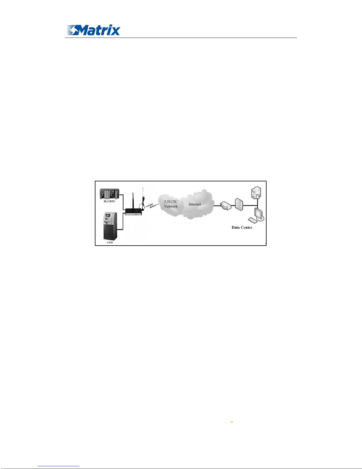
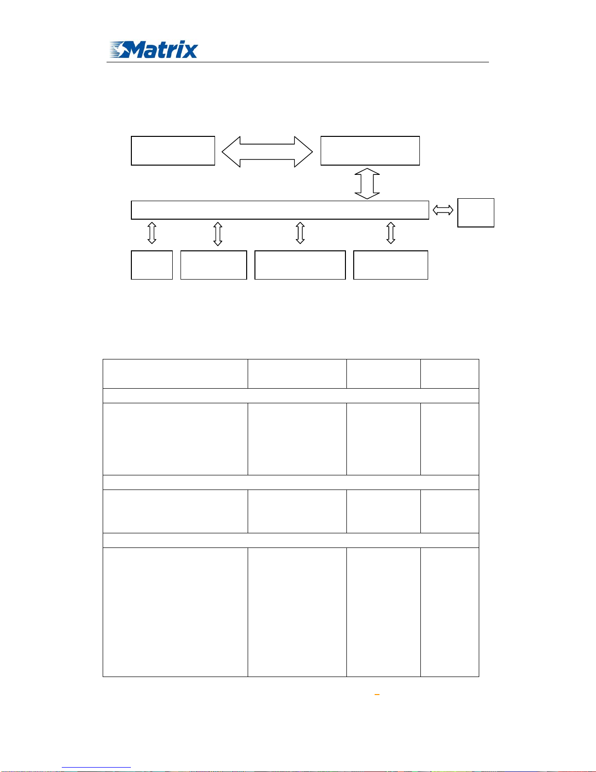
1.3 Working Principle
The principle chart of the router is as following:
1.4 Specifications
Cellular Specification
Standard and Band Bandwidth TX power RX
sensitivity
MTX-ROUTER GPRS ROUTER
EGSM900/GSM1800MHz,
GSM850/900/1800/1900MHz
(optional)
Compliant to GSM phase 2/2+
GPRS class 10, class 12(optional)
85.6Kbps GSM850/900:
<33dBm
GSM1800/1900:
<30dBm
<-107
dBm
MTX-ROUTER CDMA
CDMA2000 1xRTT 800MHz
800/1900MHz(optional)
450MHz(optional)
153.6Kbps
<30dBm <-104
dBm
MTX- ROUTER 3G
UMTS/WCDMA/HSDPA/HSUPA
/HSPA+ 850/1900/2100MHz
850/900/1900/2100MHz(optional)
GSM850/900/1800/1900MHz
GPRS/EDGE CL ASS 12
HSUPA:5.76Mbps
(Upload speed)
HSDPA:7.2Mbps
(Download speed)
UMTS:384Kbps (DL/UL)
HSPA+:
21 Mbps
<24dBm <-109
dBm
Embedded processing
system
Cellular Module
Power
RS232 serial
Interface
Indicator lights
DATA Interface
User interface
10/100M Ethernet
Interface
WIFI
Page 11

MTX-ROUTER User Manual
Matrix Electronica S.L Page 11 of 87
Add: Alejandro Sanchez 109, 28019 Ma dr id. ESPAÑA
http://www.mtx-terminals.com Tel:+34-91.560.27.37 Fax:+34+34-91.565.28.65
(Download speed)
5.76Mbps(Upload speed)
MTX- ROUTER L TE WIFI
LTE FDD
2600/2100/1800/900/800MHz,
700/1700/2100MHz(optional)
HSPA+/HSDPA/HSUPA/WCDM
A /UMTS900/2100MHz,
800/850/1900/2100MHz(optional)
EDGE/GPRS/GSM
900/1800/1900MHz
GPRS CLASS 10
GPRS CLASS 12
LTE(DL:100Mbps,UL
:50Mbps)
HSUPA:5.76Mbps(Up
load speed)
HSDPA:7.2Mbps(Do
wnload speed)
UMTS:384Kbps
(DL/UL)
HSPA+:
21Mbps(Download
speed)
5.76Mbps(Upload
speed)
<32dBm
<-93.3dBm
WIFI Specification
Item Content
Standard IEEE802.11b/g/n
Bandwidth IEEE802.11b/g: 54Mbps (max)
IEEE802.11n: 150Mbps (max)
Security WEP, WP A, W PA2, etc.
WPS (optional)
TX power
21.5dBm(11g), 26dBm(11b)
RX sensitivity <-72dBm@54Mpbs
Hardware System
Item Content
CPU Industrial 32bits CPU
FLASH 8MB(Extendable to 16MB)
RAM 64MB
Interface T ype
Item Content
Ethernet 1 10/100 Mbps Ethernet port(RJ45), auto MDI/MDIX, 1.5KV magnetic
isolation protection
Serial 1 RS232(or RS485/RS422) port, 15KV ESD protection
Data bits: 5, 6 ,7, 8
Stop bits: 1, 1.5(optional), 2
Parity: none, even, odd, (space, mark) (optional)
Baud rate: 2400~115200 bps
Page 12

MTX-ROUTER User Manual
Matrix Electronica S.L Page 12 of 87
Add: Alejandro Sanchez 109, 28019 Ma dr id. ESPAÑA
http://www.mtx-terminals.com Tel:+34-91.560.27.37 Fax:+34+34-91.565.28.65
Indicator "Power", "System", "Online", "Link/ACT ", "WIFI","Signal Strength"
Antenna Cellular: Standard SMA female interface, 50 ohm, lighting
protection(optional)
WIFI: Standard SMA male interface, 50 ohm, lighting
protection(optional)
SIM/UIM Standard 3V/1.8V user card interface, 15KV ESD protection
Power Standard 3-PIN power jack, reverse-voltage and overvoltage protection
Reset Restore the router to its original factory default settings
Power Input
Item Content
Standard Power DC 12V/1.5A
Power Range DC 5~35V
Consumption <450mA (12V)
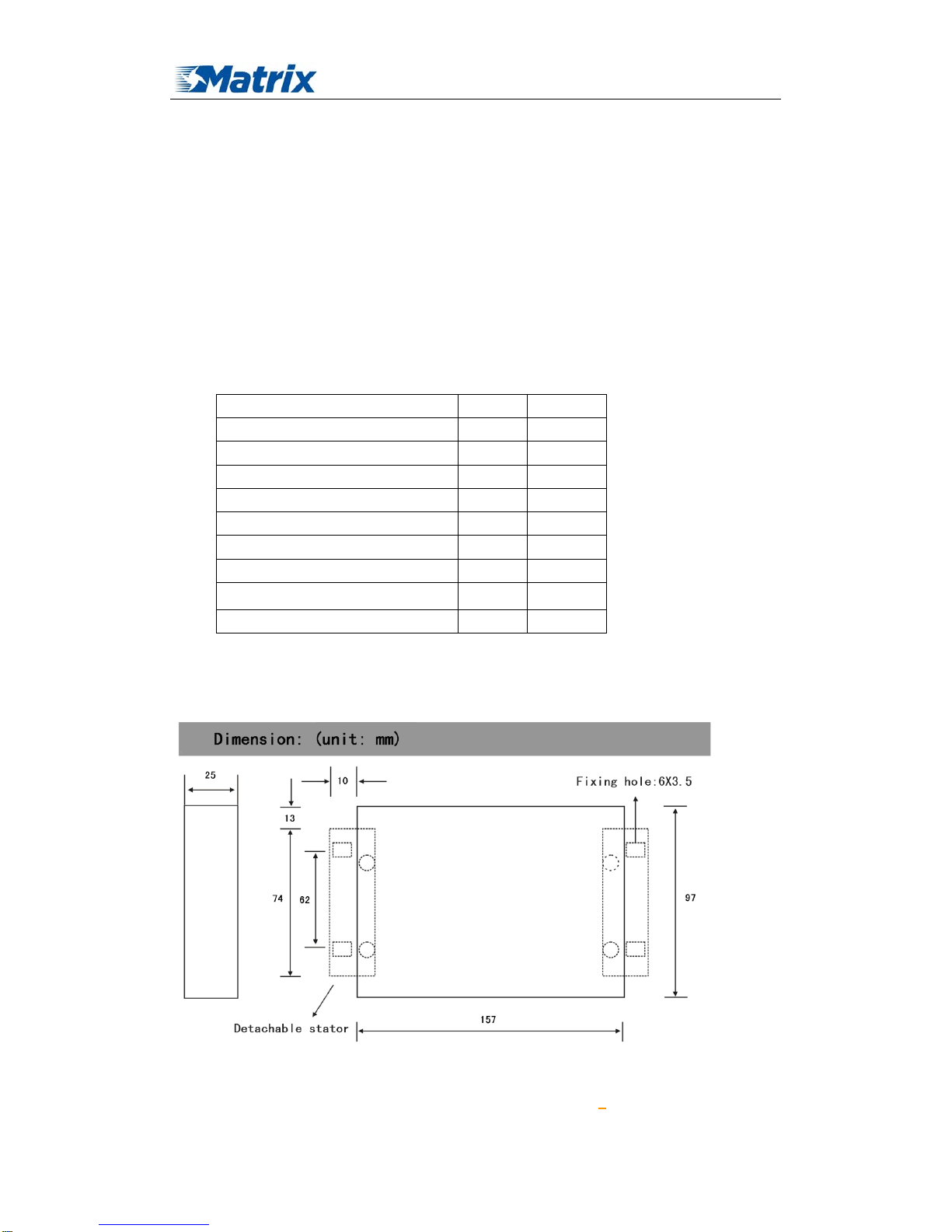
Physical Characteristics
Item Content
Housing Iron, providing IP30 protection
Dimensions 157x97x25 mm
Weight 440g
Environmental Limits
Item Content
Operating
Temperature
-35~+75ºC(-31~+167℉)
Storage
Temperature
-40~+85ºC(-40~+185℉)
Operating
Humidity
95% ( Non-condensing)
Page 13
MTX-ROUTER User Manual
Matrix Electronica S.L Page 13 of 87
Add: Alejandro Sanchez 109, 28019 Ma dr id. ESPAÑA
http://www.mtx-terminals.com Tel:+34-91.560.27.37 Fax:+34+34-91.565.28.65
Chapter 2 Installation Introduction
2.1 General
The router must be installed correctly to make it work properly.
Warning: Forbid to install the router when powered!
2.2 Encasement List
Name Quantity Remark
Router host 1
Cellular antenna (Male SMA) 1
WIFI antenna (Female SMA) 1
Network cable 1
Console cable 1 optional
Power adapter 1
Manual CD 1
Certification card 1
Maintenance card 1
2.3 Installation and Cable Connection
Installation of SIM/UIM card:
Page 14

MTX-ROUTER User Manual
Matrix Electronica S.L Page 14 of 87
Add: Alejandro Sanchez 109, 28019 Ma dr id. ESPAÑA
http://www.mtx-terminals.com Tel:+34-91.560.27.37 Fax:+34+34-91.565.28.65
Firstly power off the router, and press the out button of the SIM/UIM card outlet with a needle
object. Then the SIM/UIM card sheath will flick out at once. Put SIM/UIM card into the card
sheath (Pay attention to put the side which has metal point outside), and insert card sheath back to
the SIM/UIM card outlet.
Warning: Forbid to install SIM/UIM card when powered!
Installation of antenna:
Screw the SMA male pin of the cellular antenna to the female SMA interface of the router
with sign “WWAN”.
Screw the SMA female pin of the WIFI antenna to the male SMA interface of the router with
sign “WIFI”.
Warning: The cellular antenna and the WIFI antenna can not be connected wrongly. And the
antennas must be screwed tightly, or the signal quality of antenna will be influenced!
Installation of cable:
Insert one end of the network cable into the switch interface with sign “Local Network”, and
insert the other end into the Ethernet interface of user’s device. The signal connection of network
direct cable is as follows:
RJ45-1 RJ45-2
1 1
2 2
3 3
4 4
5 5
6 6
7 7
8 8
Insert the RJ45 end of the console cable into the RJ45 outlet with sign “console”, and insert
the DB9F end of the console cable into the RS232 serial interface of user’s device.
The signal connection of the console cable is as follows:
RJ45 DB9F
1 8
2 6
3 2
4 1
5 5
6 3
7 4
8 7
The signal definition of the DB9F serial communication interface is as follows:
Pin RS232 signal name The direction for Router
Page 15

MTX-ROUTER User Manual
Matrix Electronica S.L Page 15 of 87
Add: Alejandro Sanchez 109, 28019 Ma dr id. ESPAÑA
http://www.mtx-terminals.com Tel:+34-91.560.27.37 Fax:+34+34-91.565.28.65
2.4 Power
The power range of the router is DC 5~35V.
Warning: When we use other power, we should make sure that the power can supply power
above 7W.
We recommend user to use the standard DC 12V/1.5A power.
2.5 Indicator Lights In troduction
The router provides following indicator lights: “Power”, “System”, “Online”,
“Link/ACT”,“WIFI”, “Signal Strength”.
Indicator
Light
State Introduction
Power ON Router is powered on
OFF Router is powered off
System BLINK System works properly
OFF System does not work
Online ON Router has logged on network
OFF Router hasn’t logged on network
Link/ACT OFF The corresponding interface of switch is not
connected
ON /
BLINK
The corresponding interface of switch is connected
/Communicating
WIFI OFF WIFI is not active
ON WIFI is active
Signal
Strength
One Light
ON
Signal strength is weak
Two Lights
ON
Signal strength is medium
1 DCD output
2 RXD output
3 TXD input
4 DTR input
5 GND
6 DSR output
7 RTS input
8 CTS output
Page 16

MTX-ROUTER User Manual
Matrix Electronica S.L Page 16 of 87
Add: Alejandro Sanchez 109, 28019 Ma dr id. ESPAÑA
http://www.mtx-terminals.com Tel:+34-91.560.27.37 Fax:+34+34-91.565.28.65
Three
Lights ON
Signal strength is good
2.6 Reset Button Introduction
The router has a “Reset” button to restore it to its origin al factor y default settings. W hen user
press the “Reset” button for up to 15s, the router will restore to its original fac tory def ault settings
and restart automatically.
Chapter 3 Configuration and Management
This chapter describes how to configure and manage the router.
Page 17
MTX-ROUTER User Manual
Matrix Electronica S.L Page 17 of 87
Add: Alejandro Sanchez 109, 28019 Ma dr id. ESPAÑA
http://www.mtx-terminals.com Tel:+34-91.560.27.37 Fax:+34+34-91.565.28.65
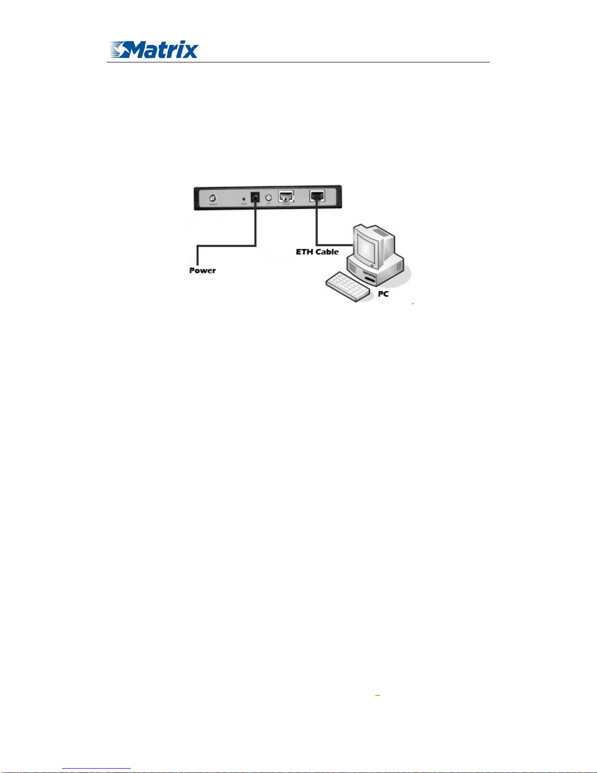
3.1 Configuration Connect io n
Before configuration, you should connect the router and your configuration PC with the
supplied network cable. Plug the cable’s one end into the Local Network port of the router, and
another end into your configure PC’s Ethernet port. The connection diagram is as following:
Please modify the IP address of PC as the same network segment address of the router, for
instance, 192.168.1.9. Modify the mask code of PC as 255.255.255.0 and set the default gateway
of PC as the router’s IP address (192.168.1.2).
3.2 Access the Configuration Web Page
The chapter is to present main functions of each page. Users visit page tool via web browser
after connect users' PC to the router. There are eleven main pages: Setting, Wireless, Service, VPN,
Security, Access Restrictions, NAT, QoS Setting, Applications, Management and Status. Users
enable to browse slave pages by click one main page.
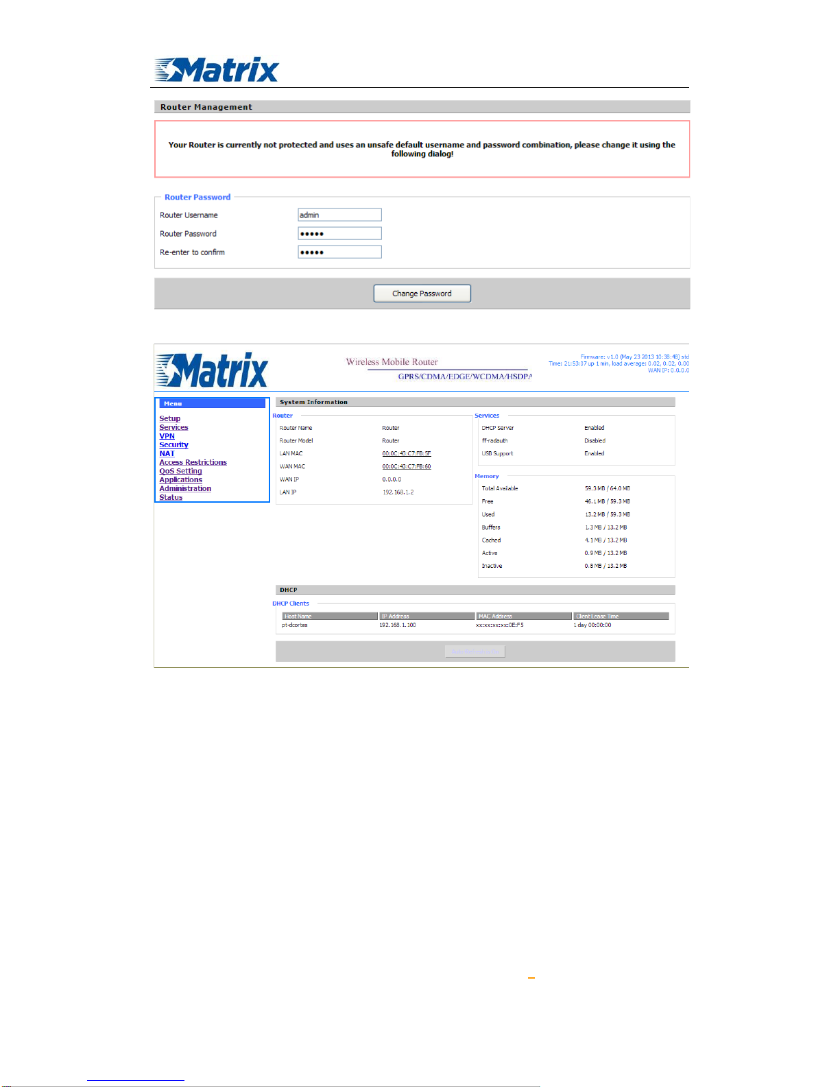
Users can open IE or other explorers and enter the router's default IP address of 192.168.1.2
on address bar, then press the botton of Enter to visit page Web management tool of the router.
The users login in the web page at the first name, there will display a page shows as blow to tip
users to modify the default user name and password of the router. Users have to click "change
password" to make it work if they modify user name and password.
Page 18
MTX-ROUTER User Manual
Matrix Electronica S.L Page 18 of 87
Add: Alejandro Sanchez 109, 28019 Ma dr id. ESPAÑA
http://www.mtx-terminals.com Tel:+34-91.560.27.37 Fax:+34+34-91.565.28.65
After access to the information main page
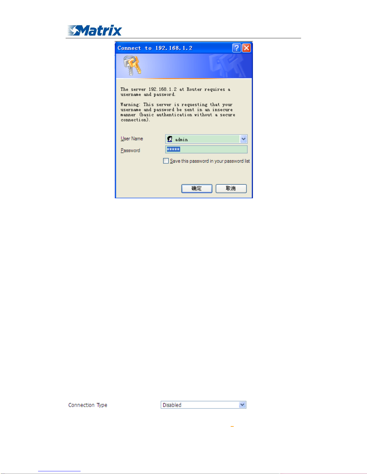
Users need to input user name and password if it is their first time to login.
Page 19
MTX-ROUTER User Manual
Matrix Electronica S.L Page 19 of 87
Add: Alejandro Sanchez 109, 28019 Ma dr id. ESPAÑA
http://www.mtx-terminals.com Tel:+34-91.560.27.37 Fax:+34+34-91.565.28.65
Input correct user name and password to visit relevant menu page. Default user name is admin,
password is admin. (available to modify user name and password on management page, then click
submit)
3.3 Management and configuration
3.3.1 Setting
The Setup screen is the first screen users will see when accessing the router. Most users will be
able to configure the router and get it work properly using only the settings on this screen. Some
Internet Service Providers (ISPs) will require users to enter specific information, such as User
Name, Password, IP Address, Default Gateway Address, or DNS IP Address. These information
can be obtained from your ISP, if required.
3.3.1.1 Basic Setting
WAN Connection Type
Seven Ways: Disabled, 3G/UNMTS/4G/LTE
Disabled
Page 20
MTX-ROUTER User Manual
Matrix Electronica S.L Page 20 of 87
Add: Alejandro Sanchez 109, 28019 Ma dr id. ESPAÑA
http://www.mtx-terminals.com Tel:+34-91.560.27.37 Fax:+34+34-91.565.28.65
Forbid the setting of WAN port connection type
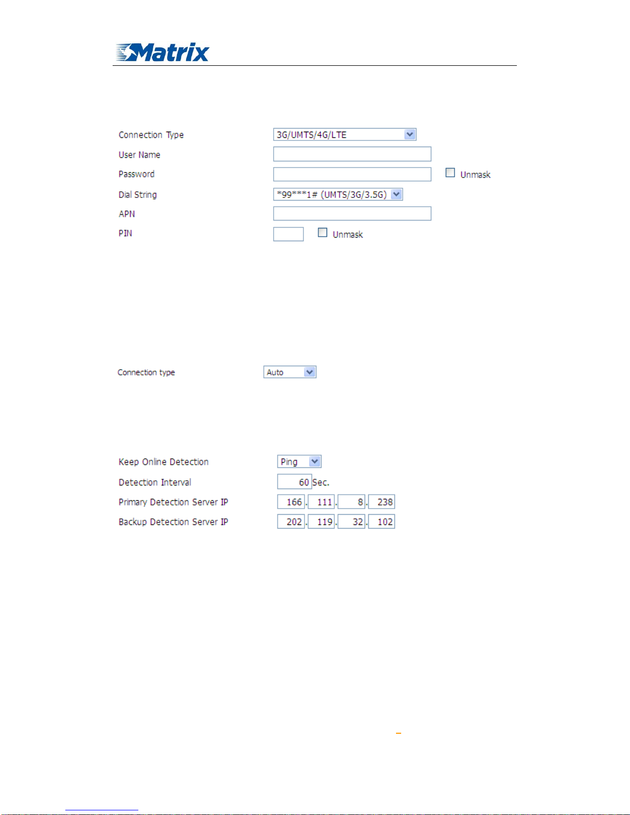
3G/UMTS/4G/LTE
User Name: login users' ISP(Internet Service Provider)
Password: login users' ISP
Dial String: dial number of users' ISP
APN: access point name of users' ISP
PIN: PIN code of users' SIM card
Connection type
Connection type: Auto, Force 3G, Force 2G, Prefer 3G, Prefer 2G options. If using 4G module,
there has 4G network option. Users select different mode depending on their need
Keep Online
This function is used to detect whether the Internet connection is active, if users set it and whe n
the router detect the connection is inactive, i t will redial to users' ISP immediately to make the
connection active.
Detection Method:
None: do not set this function
Ping: Send ping packet to detect the connection, when choose this method, users should also
configure "Detection Interval", "Primary Detection Server IP" and "Backup Detection
Server IP" items.
Route: Detect connection with route method, when choose this method, users should also
configure "Detection Interval", "Primary Detection Server IP" and "Backup Detection
Server IP" items.
PPP: Detect connection with PPP method, when choose this method, users should also
Page 21
MTX-ROUTER User Manual
Matrix Electronica S.L Page 21 of 87
Add: Alejandro Sanchez 109, 28019 Ma dr id. ESPAÑA
http://www.mtx-terminals.com Tel:+34-91.560.27.37 Fax:+34+34-91.565.28.65
configure "Detection Interval" item.
Detection Interval: time interval between two detections, unit is second
Primary Detection Server IP: the server used to response the router’s detection packet. This item
is only valid for method "Ping" and "Route".
Backup Detection Server IP: the server used to response the router’s detection packet. This item
is valid for method "Ping" and "Route".
Note: When users choose the “Route” or “Ping” method, it’s quite important to make sure
that the “Primary Detection Server IP” and “Backup Detection Server IP” are usable and stable,
because they have to response the detection packet frequently.
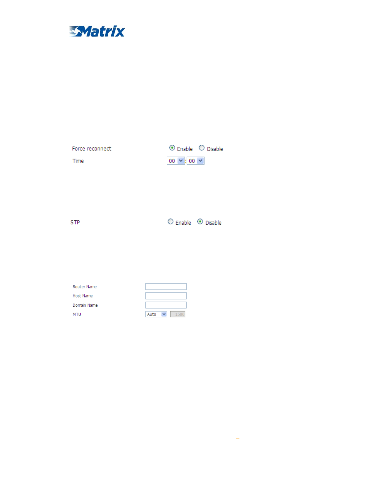
Force reconnect: this option schedules the pppoe or 3G reconnection by killing the pppd daemon
and restart it.
Time: needed time to reconnect
STP
STP (Spaning Tree Protocol) can be applied to loop network. Through certain algorithm achieves
path redundancy, and loop network cuts to tree-based network without loop in the meantime, thus
to avoid the hyperplasia and infinite circulation of a message in the loop network
Optional Configuration
Router Name: set router name
Host Name: ISP provides
Domain Name: ISP provides
MTU: auto (1500) and manual (1200-1492 in PPPOE/PPTP/L2TP mode, 576-16320 in other
modes)
Router Internal Network Settings
Router IP
Page 22
MTX-ROUTER User Manual
Matrix Electronica S.L Page 22 of 87
Add: Alejandro Sanchez 109, 28019 Ma dr id. ESPAÑA
http://www.mtx-terminals.com Tel:+34-91.560.27.37 Fax:+34+34-91.565.28.65
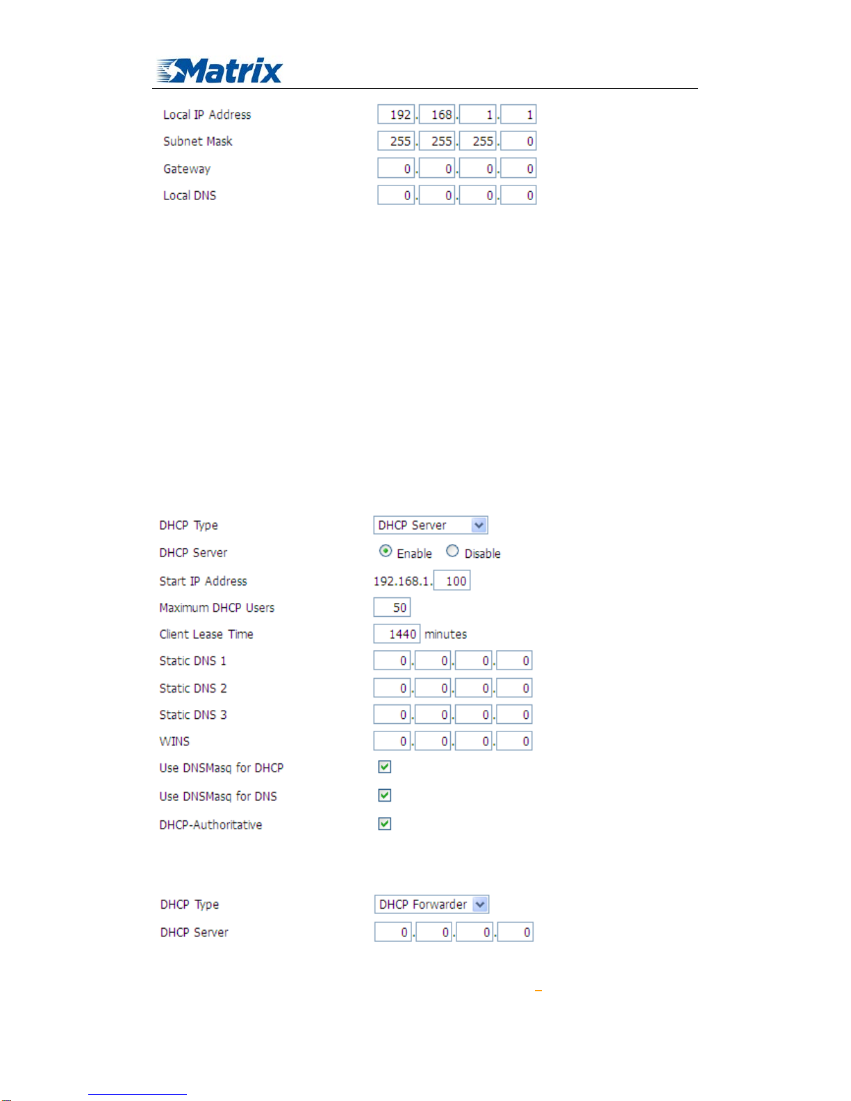
Local IP Address: IP address of the router
Subnet Mask: the subnet mask of the router
Gateway: set internal gateway of the router. If default, internal gateway is the address of the
router
Local DNS: DNS server is auto assigned by network operator server. Users enable to use their
own DNS server or other stable DNS servers, if not, keep it default
Network Address Server Settings (DHCP)
These settings for the router's Dynamic Host Configuration Protocol (DHCP) server functionality
configuration. The Router can serve as a network DHCP server. DHCP server automatically
assigns an IP address for each computer in the network. If they choose to enable the router's
DHCP server option, users can set all the computers on the LAN to automatically obtain an IP
address and DNS, and make sure no other DHCP server in the network.
DHCP Type: DHCP Server and DHCP Forwarder
Enter DHCP Server if set DHCP Type to DHCP Forwarder as blow:
DHCP Server: keep the default Enable to enable the router's DHCP server option. If users have
Page 23
MTX-ROUTER User Manual
Matrix Electronica S.L Page 23 of 87
Add: Alejandro Sanchez 109, 28019 Ma dr id. ESPAÑA
http://www.mtx-terminals.com Tel:+34-91.560.27.37 Fax:+34+34-91.565.28.65
already have a DHCP server on their network or users do not want a DHCP server, then select
Disable
Start IP Address: enter a numerical value for the DHCP server to start with when issuing IP
addresses. Do not start with 192.168.1.2 (the router's own IP address).
Maximum DHCP Users: enter the maximum number of PCs that users want the DHCP server to
assign IP addresses to. The absolute maximum is 253 if 192.168.1.2 is users' starting IP address.
Client Lease Time: the Client Lease Time is the amount of time a network user will be allowed
connection to the router with their current dynamic IP address. Enter the amount of time, in
minutes, that the user will be "leased" this dynamic IP address.
Static DNS (1-3): the Domain Name System (DNS) is how the Internet translates domain or
website names into Internet addresses or URLs. Users' ISP will provide them with at least one
DNS Server IP address. If users wish to utilize another, enter that IP address in one of these fields.
Users can enter up to three DNS Server IP addresses here. The router will utilize them for quicker
access to functioning DNS servers.
WINS: the Windows Internet Naming Service (WINS) manages each PC's interaction with the
Internet. If users use a WINS server, enter that server's IP address here. Otherwise, leave it blank.
DNSMasq: users' domain name in the field of local search, increase the expansion of the host
option, to adopt DNSMasq can assign IP addresses and DNS for the subnet, if select
DNSMasq, dhcpd service is used for the subnet IP address and DNS.
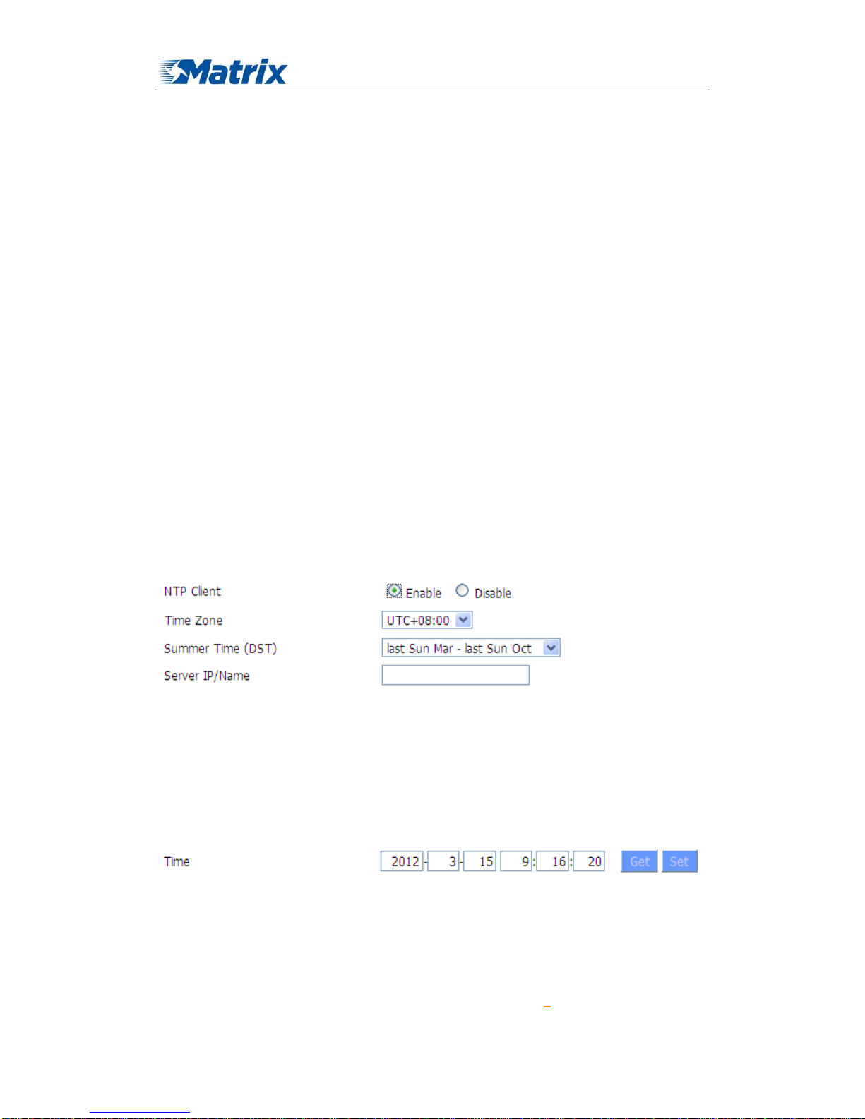
Time Settings
Select time zone of your location. To use local time, leave the checkmark in the box next to Use
local time.
NTP Client: Get the system time from NTP server
Time Zon e: Time zone options
Summer Time (DST): set it depends on users' location
Server IP/Name: IP address of NTP server, up to 32 characters. If blank, the system will find a
server by default
Adjust Time
To adjust time by the system and refresh to get the time of the web, user can set to modify the
time of the system. They can change to adjust time by manual to achieve adjust time by the
system if the system fails to get NTP server
Page 24
MTX-ROUTER User Manual
Matrix Electronica S.L Page 24 of 87
Add: Alejandro Sanchez 109, 28019 Ma dr id. ESPAÑA
http://www.mtx-terminals.com Tel:+34-91.560.27.37 Fax:+34+34-91.565.28.65
3.3.1.2 Dynamic DNS
If user's network has a permanently assigned IP address, users can register a domain name
and have that name linked with their IP address by public Domain Name Servers (DNS).
However, if their Internet account uses a dynamically assigned IP address, users will not
know in advance what their IP address will be, and the address can change frequently. In this
case, users can use a commercial dynamic DNS service, which allows them to register their
domain to their IP address, and will forward traffic directed at their domain to their
frequently-changing IP address.
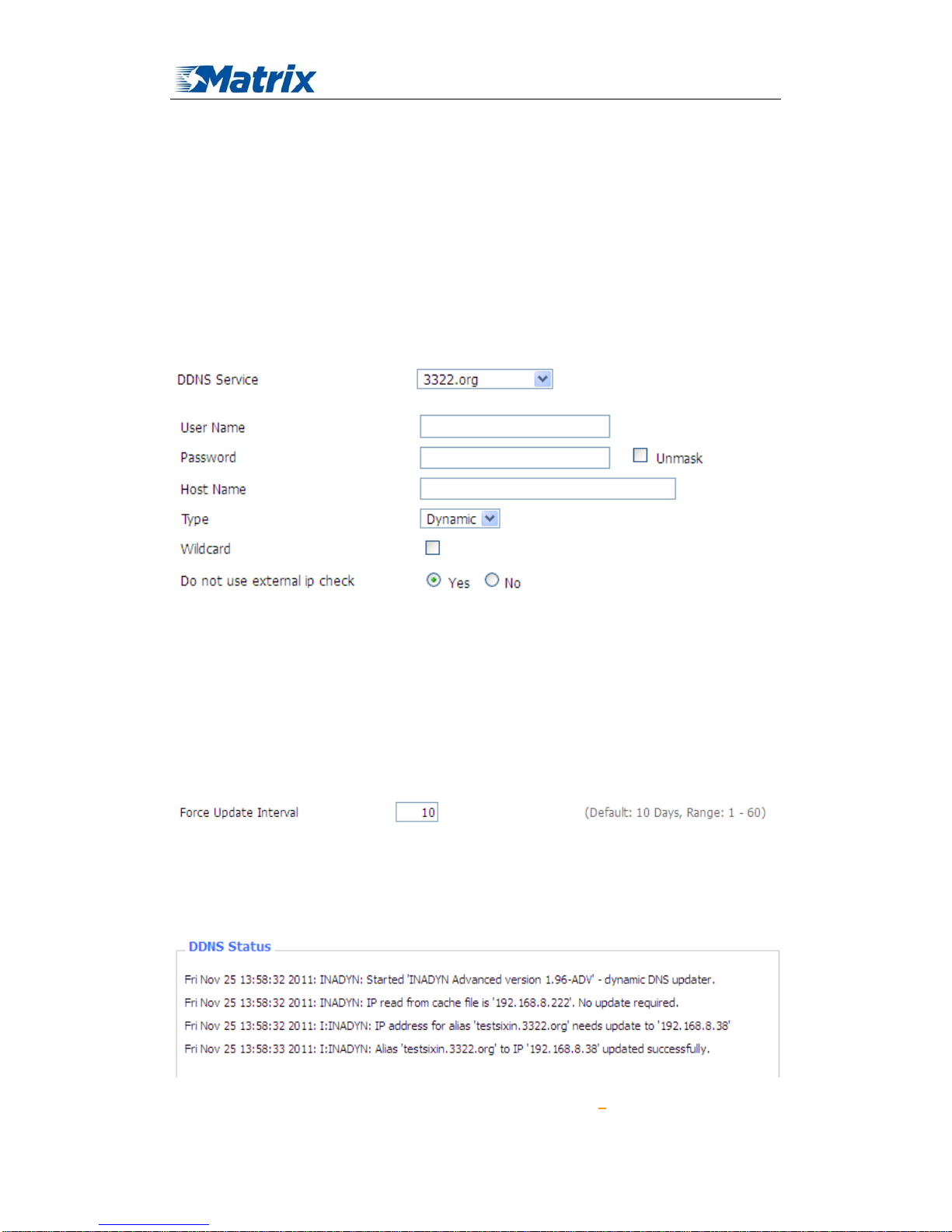
DDNS Service: MTX-ROUTER currently support DynDNS, freedns, Zoneedit, NO-IP, 3322,
easyDNS, TZO, DynSIP and Custom based on the user.
User Name: users register in DDNS server, up to 64 characteristic
Password: password for the user name that users register in DDNS server, up to 32 characteristic
Host Name: users register in DDNS server, no limited for input characteristic for now
Type: depends on the server
Wildcard: support wildcard or not, the default is OFF. ON means *.host.3322.org is equal to
host.3322.org
Do not use external ip check: enable or disable the function of 'do not use external ip check'
Force Update Interval: unit is day, try forcing the update dynamic DNS to the server by setted
days
Status
Page 25
MTX-ROUTER User Manual
Matrix Electronica S.L Page 25 of 87
Add: Alejandro Sanchez 109, 28019 Ma dr id. ESPAÑA
http://www.mtx-terminals.com Tel:+34-91.560.27.37 Fax:+34+34-91.565.28.65
DDNS Status shows connection log information
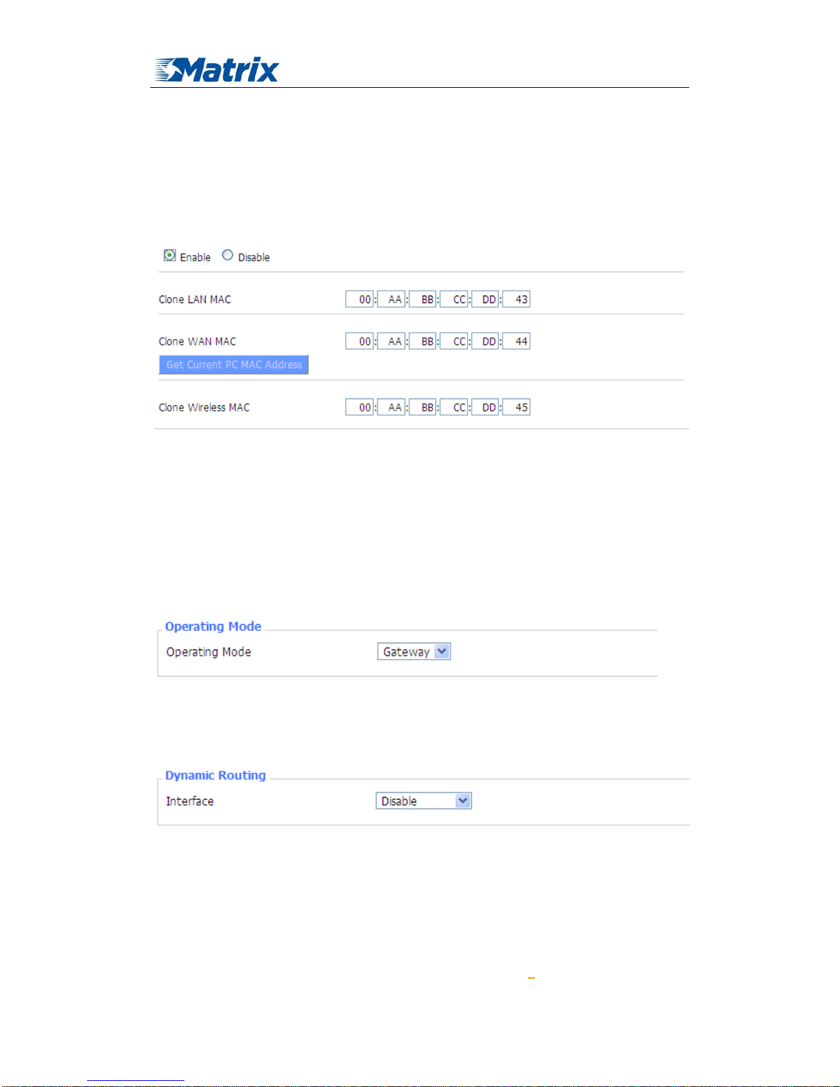
3.3.1.3 Clone MAC Address
Some ISP need the users to register their MAC address. The users can clone the router MAC
address to their MAC address registered in ISP if they do not want to re-register their MAC
address
Clone MAC address can clone three parts: Clone LAN MAC, Clone WAN MAC, Clone Wireless
MAC.
Noted that one MAC address is 48 characteristic, can not be set to the multicast address, the first
byte must be even. And MAC address value of network bridge br0 is determined by the smaller
value of wireless MAC address and LAN port MAC address.
3.3.1.4 Advanced Router
Operating Mode: Gateway and Router
If the router is hosting users' Internet connection, select Gateway mode. If another router exists on
their network, select Router mode.
Dynamic Routing
Dynamic Routing enables the router to automatically adjust to physical changes in the network's
layout and exchange routing tables with other routers. The router determines the network packets’
route based on the fewest number of hops between the source and destination.
To enable the Dynamic Routing feature for the WAN side, select WAN. To enable this feature for
the LAN and wireless side, select LAN&WLAN. To enable the feature for both the WAN and
LAN, select Both. To disable the Dynamic Routing feature for all data transmissions, keep the
Page 26
MTX-ROUTER User Manual
Matrix Electronica S.L Page 26 of 87
Add: Alejandro Sanchez 109, 28019 Ma dr id. ESPAÑA
http://www.mtx-terminals.com Tel:+34-91.560.27.37 Fax:+34+34-91.565.28.65
default setting, Disable.
Note
:Dynamic Routing is not available in Gateway mode
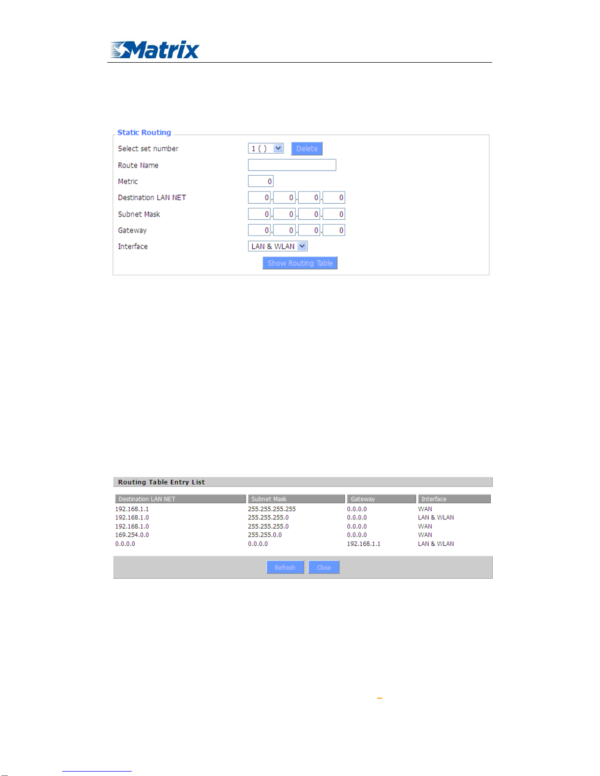
Static Routing
Select set number: 1-50
Route Name: defined routing name by users, up to 25 characters
Metric: 0-9999
Destination LAN NET: the Destination IP Address is the address of the network or host to which
users want to assign a static route
Subnet Mask: the Subnet Mask determines which portion of an IP address is the network portion,
and which portion is the host portion
Gateway: IP address of the gateway device that allows for contact between the router and the
network or host.
Interface: indicate users whether the Destination IP Address is on the LAN & WLAN (internal
wired and wireless networks), the WAN (Internet), or Loopback (a dummy network in which one
PC acts like a network, necessary for certain software programs)
Show Routing T able
3.3.1.5 Networking
Page 27
MTX-ROUTER User Manual
Matrix Electronica S.L Page 27 of 87
Add: Alejandro Sanchez 109, 28019 Ma dr id. ESPAÑA
http://www.mtx-terminals.com Tel:+34-91.560.27.37 Fax:+34+34-91.565.28.65
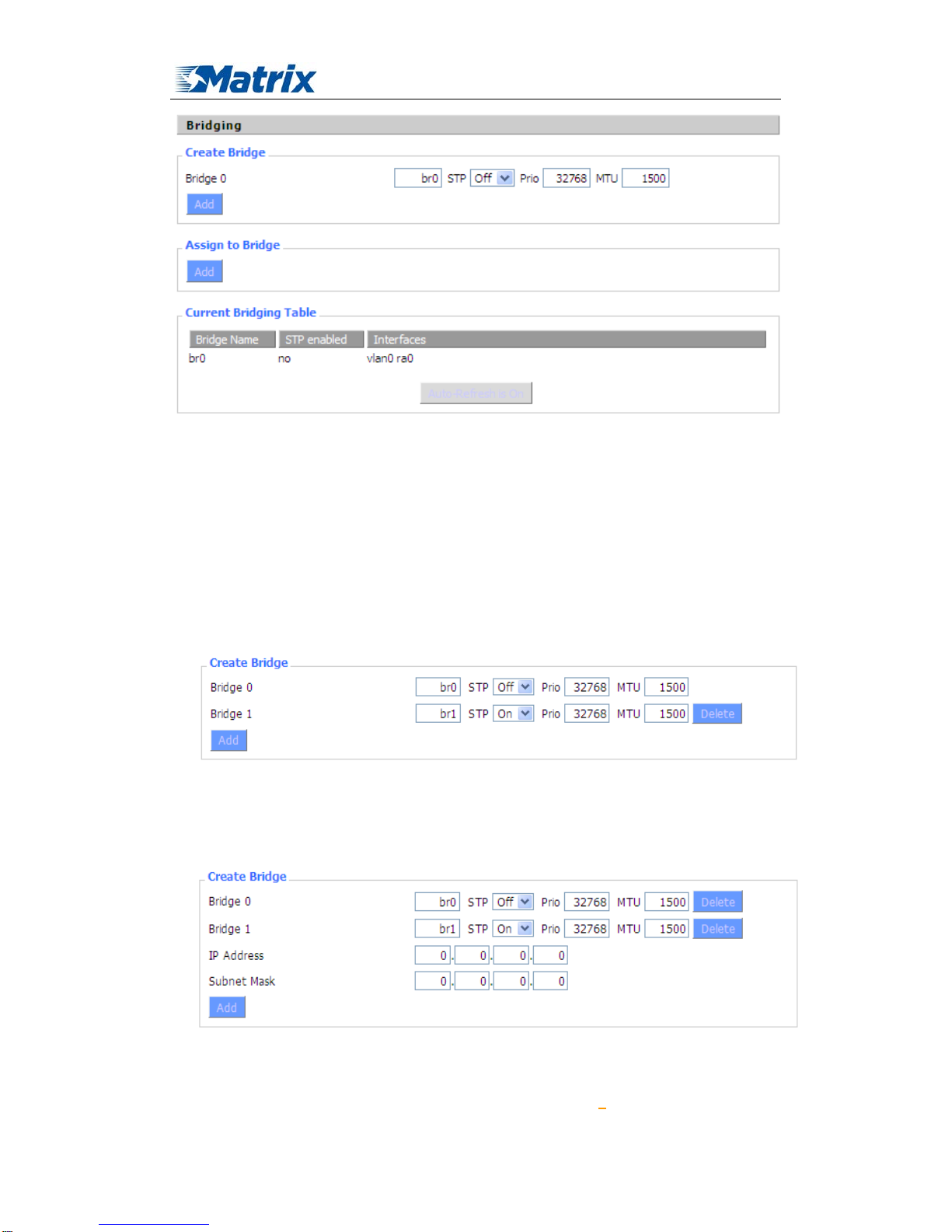
Bridging-Create Bridge: creates a new empty network bridge for later use. STP means Spanning
Tree Protocol and with PRIO users are able to set the bridge priority order. The lowest number has
the highest priority.
Bridging - Assign to Bridge: allows users to assign any valid interface to a network bridge.
Consider setting the Wireless Interface options to Bridged if they want to assign any Wireless
Interface here. Any system specific bridge setting can be overridden here in this field.
Current Bridging Table: shows current bridging table
Create steps as below:
Click 'Add' to create a new bridge, configuration is as below:
Create bridge option: the first br0 means bridge name. STP means to on/off spanning tree
protocol. Prio means priority level of STP, the smaller the number, the higher the level. MTU
means maximum transfer unit, default is 1500, delete if it is not need. And then click 'Save' or
'Add'. Bride properties is as below:
Enter relewant bridge IP address and subnet mask, click 'Add' to create a bridge.
Note: Only create a bride can apply it.
Page 28

MTX-ROUTER User Manual
Matrix Electronica S.L Page 28 of 87
Add: Alejandro Sanchez 109, 28019 Ma dr id. ESPAÑA
http://www.mtx-terminals.com Tel:+34-91.560.27.37 Fax:+34+34-91.565.28.65
Assign to Bridge option: to assign different ports to created bridge. For example: assign port
(wireless port) is ra0 in br1 bridge as below:
Prio means priority level: work if multiple ports are within the same bridge. The smaller the
number, the higher the level. Click 'Add' to take it effect.
Note: corresponding interface of WAN ports interface should not be binding, this bridge
function is basically used for LAN port, and should not be binding with WAN port
If bind success, bridge binding list in the list of current bridging table is as below:
To make br1 bridge has the same function with DHCP assigned address, users need to set
multiple DHCP function, see the introduction of multi-channel DHCPD:
Port Setup: Set the port property, the default is not set
Page 29

MTX-ROUTER User Manual
Matrix Electronica S.L Page 29 of 87
Add: Alejandro Sanchez 109, 28019 Ma dr id. ESPAÑA
http://www.mtx-terminals.com Tel:+34-91.560.27.37 Fax:+34+34-91.565.28.65
Choose not bridge to set the port's own properties, detailed properties are as below:
MTU: maximum transfer unit
Multicast forwarding: enable or disable multicast forwarding
Masquerade/NAT: enable or disable Masquerade/NAT
IP Address: set ra0's IP address, and do not conflict with other ports or bridge
Subnet Mask: set the port's subnet mask
Multiple DHCPD: using multiple DHCP service. Click 'Add' in multiple DHCP server to appear
relevant configuration. The first means the name of port or bridge (do not be configured as
eth0), the second means whether to on DHCP. Start means start address, Max means
maximum assigned DHCP clients, Leasetime means the client lease time, the unit is
second, click 'Save' or 'Apply' to put it into effect after setting.
Note: Only configure and click 'Save' can configure the next, can not configure multiple DHCP at
the same time.
3.3.2 Wireless
3.3.2.1 Basic Settings
Page 30
MTX-ROUTER User Manual
Matrix Electronica S.L Page 30 of 87
Add: Alejandro Sanchez 109, 28019 Ma dr id. ESPAÑA
http://www.mtx-terminals.com Tel:+34-91.560.27.37 Fax:+34+34-91.565.28.65
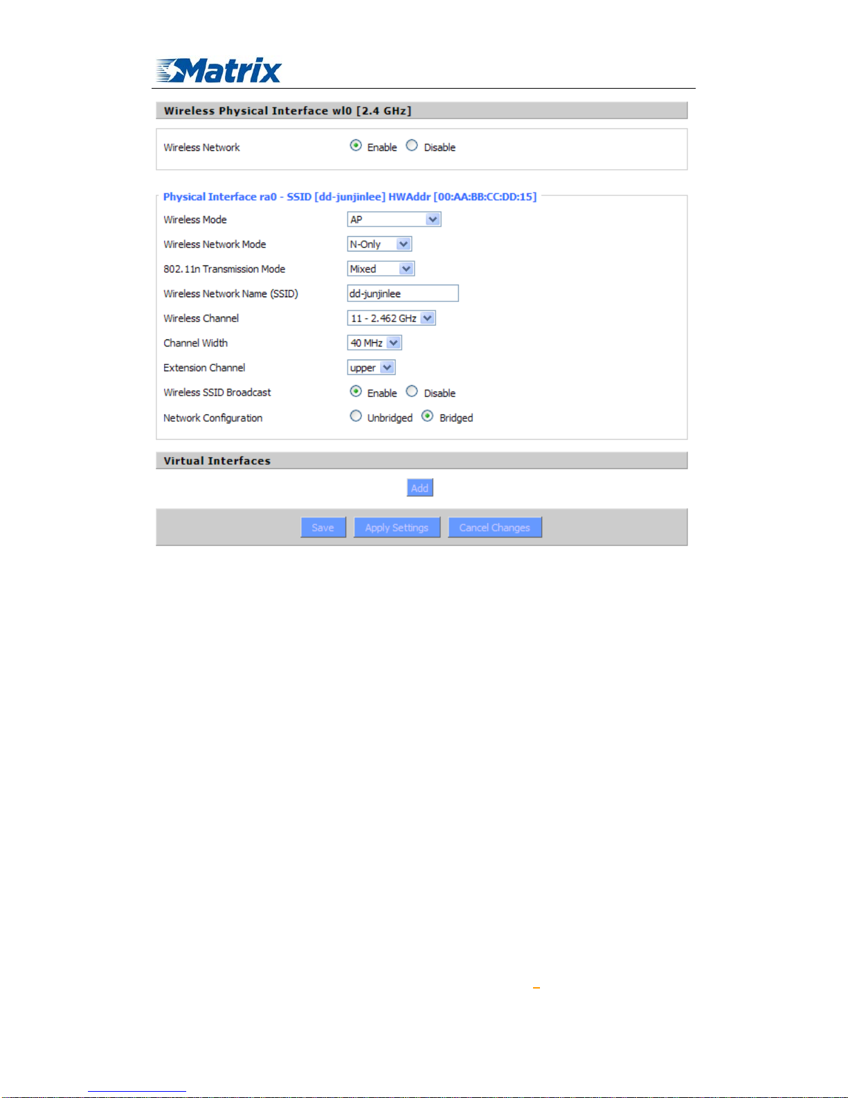
Wireless Network:“Eanble”, radio on.
“Disable”, radio off.
Wireless Mode:AP, Client, Adhoc, Repeater, Repeater Bridge four options。
Wireless Network Mode:
Mixed:Support 802.11b, 802.11g, 802.11n wireless devices.
BG-Mixed:Support 802.11b, 802.11g wireless devices.
B-only:Only supports the 802.11b standard wireless devices.
B-only:Only supports the 802.11b standard wireless devices.
G-only:Only supports the 802.11g standard wireless devices.
NG-Mixed:Support 802.11g, 802.11n wireless devices.
N-only
:Only supports the 802.11g standard wireless devices.
8021.11n Transmission Mode:In the wireless network mode to "N-only" ch oose to transfer its
transmission mode.
Greenfield: When you determine the surrounding environment, there is no other 802.11a/b/g
devices use the same channel, use this mode to increase throughput. Other 802.11a/b/g devices use
the same channel in the environment, the information you send may generate an error, re-issued.
Mixed:This mode is contrary to the green mode, but will reduce the throughput.
Wireless Network Name(SSID): The SSID is the network name shared among all devices in a
wireless network. The SSID must be identical for all devices in the wireless network. It is
case-sensitive and must not exceed 32 alphanumeric characters, which may be any keyboard
Page 31

MTX-ROUTER User Manual
Matrix Electronica S.L Page 31 of 87
Add: Alejandro Sanchez 109, 28019 Ma dr id. ESPAÑA
http://www.mtx-terminals.com Tel:+34-91.560.27.37 Fax:+34+34-91.565.28.65
character. Make sure this setting is the same for all devices in your wireless network.。
Wireless Channel:A total of 1-13 channels to choose more than one wireless device environment,
please try to avoid using the same channel with other devices.。
Channel Width:20MHZ and 40MHZ。
Extension Channel:Channel for 40MHZ, you can choose upper or lower.
Wireless SSID Broadcast:
Enable:SSID broadcasting.
Disable:Hidden SSID.
Network Configuration:
Bridged:Bridge to the router, under normal circumstances, please select the bridge.
Unbridged:There is no bridge to the router, IP addresses need to manually configure.
Virtual Interfaces:Click Add to add a virtual interface. Add successfully, click on the remove,
you can remove the virtual interface。
AP Isolation:This setting isolates wireless clients so access to and from other wireless clients are
stopped.
Note:Save your changes, after changing the "Wireless Mode", "Wireless Network Mode",
"wireless width", "broadband" option, please click on this button, and then configure the other
options.
3.3.2.2 Wireless Security
Wireless security options used to configure the security of your wireless network. This route is
a total of seven kinds of wireless security mode. Disabled by default, not safe mode is enabled.
Such as changes in Safe Mode, click Apply to take effect immediately.
Page 32

MTX-ROUTER User Manual
Matrix Electronica S.L Page 32 of 87
Add: Alejandro Sanchez 109, 28019 Ma dr id. ESPAÑA
http://www.mtx-terminals.com Tel:+34-91.560.27.37 Fax:+34+34-91.565.28.65
WEP:Is a basic encryption algorithm is less secure than WPA.Use of WEP is discouraged due to
security weaknesses, and one of the WPA modes should be used whenever possible. Only use
WEP if you have clients that can only support WEP (usually older, 802.11b-only clients).
Authentication Type:Open or shared key。
Default Transmit Key:Select the key form Key 1 - Key 4 key.
Encryption:There are two levels of WEP encryption, 64-bit (40-bit) and 128-bit. To utilize WEP,
select the desired encryption bit, and enter a passphrase or up to four WEP key in hexadecimal
format. If you are using 64-bit (40-bit), then each key must consist of exactly 10 hexadecimal
characters or 5 ASCII charceters. For 128-bit, each key must consist of exactly 26 hexadecimal
characters. Valid hexadecimal characters are "0"-"9" and "A"-"F".
ASCII/HEX: ASCII, the keys is 5 bit ASCII characters/13bit ASCII characters.
HEX, the keys is 10bit/26 bit hex digits.
Passphrase
:The letters and numbers used to generate a key.
Key1-Key4:Manually fill out or generated according to input the pass phrase.
Page 33

MTX-ROUTER User Manual
Matrix Electronica S.L Page 33 of 87
Add: Alejandro Sanchez 109, 28019 Ma dr id. ESPAÑA
http://www.mtx-terminals.com Tel:+34-91.560.27.37 Fax:+34+34-91.565.28.65
WPA Personal/WPA2 Personal/WPA2 Person Mixed:, TKIP/AES/TKIP+AES , dynamic
encryption keys. TKIP + AES, self-applicable TKIP or AES. WPA Person Mixed, allow WPA
Personal and WPA2 Personal client mix.
WPA Shared Key:Between 8 and 63 ASCII character or hexadecimal digits.。
Key Renewal Interval(in seconds): 1-99999。
WPA Enterprise/WPA2 Enterprise/WPA2 Enterprise Mixed: WPA Enterprise uses an external
RADIUS server to perform user authentication.
WPA Algorithms: AES/TKIP/TPIP+AES.
Radius Auth Sever Address:The IP address of the RADIUS server.
Radius Auth Server Port:The RADIUS Port (default is 1812)。
Radius Auth Shared Secret:The shared secret from the RADIUS server。
Key Renewal Interva(in seconds): 1-99999。
Page 34

MTX-ROUTER User Manual
Matrix Electronica S.L Page 34 of 87
Add: Alejandro Sanchez 109, 28019 Ma dr id. ESPAÑA
http://www.mtx-terminals.com Tel:+34-91.560.27.37 Fax:+34+34-91.565.28.65
802.1x: 802.1x for user to connect to a wireless access point and cable converter to provide the
certification. It will limit without obtaining the user credentials to connect to the Internet,
credentials - for example, a separate server authentication user name and password.
Peap: PEAP (Protected Extensible Authentication Protocol) is a version of EAP, the
authentication protocol used in wireless networks and Point-to-Point connections. PEAP is
designed to provide more secure authentication for 802.11 WLANs (wireless local area networks)
that support 802.1X port access control. Here is PEAP-EAP-MS-CHAPv2.
1. Enter the User.
2. Enter the Password.
TTLS: TTLS uses the TLS channel to exchange "attribute-value pairs" (AVPs), much like
RADIUS. (In fact, the AVP encoding format is very similar to RADIUS.) The general encoding of
information allows a TTLS server to validate AVPs against any type of authentication mechanism.
TTLS implementations today support all methods defined by EAP, as well as several older
methods (CHAP, PAP, MS-CHAP and MS-CHAPv2). TTLS can easily be extended to work with
new protocols by defining new attributes to support new protocols.
1. Enter the User.
2. Enter the Password.
3. Enter the Public Server Certificate.
3.3.2.3 Wireless MAC Filter
The Wireless MAC Filter allows you to control which wireless-equipped PCs may or may not
communicate with the router depending on their MAC addresses. For information how to get
MAC addresses from Windows-PCs, see MAC Address Cloning for detailed instructions。
Page 35

MTX-ROUTER User Manual
Matrix Electronica S.L Page 35 of 87
Add: Alejandro Sanchez 109, 28019 Ma dr id. ESPAÑA
http://www.mtx-terminals.com Tel:+34-91.560.27.37 Fax:+34+34-91.565.28.65
Use Filter:Disabled by default. Select Enable to open the Wireless MAC Filter。
Filter Mode:
Prevent client listed from accessing the wireless network:If you want to block specific
wireless-equipped PCs from communicating with the router, then keep the default setting, Prevent
PCs listed from accessing the wireless network.
Permit only client listed to accessing the wireless network:If you want to allow specific
wireless-equipped PCs to communicate with the router, then click the radio button next to Permit
only PCs listed to access the wireless network。
Click the Edit MAC Filter List button. Enter the appropriate MAC addresse s into the MAC
fields
3.3.2.4 Advance Settings
The Wireless Advanced Settings screen allows you to customize data transmission settings.
In most cases, the advanced settings on this screen should remain at their default values。
Page 36

MTX-ROUTER User Manual
Matrix Electronica S.L Page 36 of 87
Add: Alejandro Sanchez 109, 28019 Ma dr id. ESPAÑA
http://www.mtx-terminals.com Tel:+34-91.560.27.37 Fax:+34+34-91.565.28.65
Basic Rate:The default value is set to Default. Depending on the wireless mode you have selected,
a default set of supported data rates will be selected. The default setting will ensure maximum
compatibility with all devices. You may also choose to enable all data rates by selecting ALL. For
compatibility with older Wireless-B devices, select 1-2Mbps.
MIMO-Transmission Fixed Rate:The default setting is Auto. The range is from 13.5 to
270Mbps. The rate of data transmission should be set depending on the speed of your wireless
network. You can select from a range of transmission speeds, or keep the default setting, Auto, to
have the router automatically use the fastest possible data rate and enable the Auto-Fallback
feature. Auto-Fallback will negotiate the best possible connection speed between the router and a
wireless client。
Tr ansmissi on Fixed Rate:The default setting is Auto. The range is from 1 to 54Mbps. The rate of
data transmission should be set depending on the speed of your wireless network. You can select
from a range of transmission speeds, or keep the default setting, Auto, to have the router
automatically use the fastest possible data rate and enable the Auto-Fallback feature.
Auto-Fallback will negotiate the best possible connection speed between the router and a wireless
client.
Page 37

MTX-ROUTER User Manual
Matrix Electronica S.L Page 37 of 87
Add: Alejandro Sanchez 109, 28019 Ma dr id. ESPAÑA
http://www.mtx-terminals.com Tel:+34-91.560.27.37 Fax:+34+34-91.565.28.65
CTS Protection Mode:The default value is disabled. When set to Auto, a protection mechanism
will ensure that your Wireless-B devices will connect to the Wireless-G router when many
Wireless-G devices are present. However, performance of your Wireless-G devices may be
decreased.
Frame Burst:The default value is disabled. Frame burst allows packet bursting which will
increase overall network speed though this is only recommended for approx 1-3 wireless clients,
Anymore clients and there can be a negative result and throughput will be affected.
Beacon Interval:The default value is 100. Enter a value between 1 and 65,535 milliseconds. The
Beacon Interval value indicates the frequency interval of the beacon. A beacon is a packet
broadcast by the router to synchronize the wireless network. 50 is recommended in poor reception.
DTIM Interval:The default value is 1. This value, between 1 and 255, indicates the interval of
the Delivery Traffic Indication Message (DTIM). A DTIM field is a countdown field informing
clients of the next window for listening to broadcast and multicast messages. When the router has
buffered broadcast or multicast messages for associated clients, it sends the next DTIM with a
DTIM Interval value. Its clients hear the beacons and awaken to receive the broadcast and
multicast messages.
Fragmentation Threshold
:This value should remain at its default setting of 2346. The range is
256-2346 bytes. It specifies the maximum size for a packet before data is fragmented into multiple
packets. If you experience a high packet error rate, you may slightly increase the Fragmentation
Threshold. Setting the Fragmentation Threshold too low may result in poor network performance.
Only minor modifications of this value are recommended.
RTS Threshold:This value should remain at its default setting of 2347. The range is 0-2347 bytes.
Should you encounter inconsistent data flow, only minor modifications are recommended. If a
network packet is smaller than the preset RTS threshold size, the RTS/CTS mechanism will not be
enabled. The router sends Request to Send (RTS) frames to a particular receiving station and
negotiates the sending of a data frame. After receiving an RTS, the wireless station responds with
a Clear to Send (CTS) frame to acknowledge the right to begin transmission.
Max Associated Clients:1-128.
AP Isolation
:The default value is Off. This setting isolates wireless clients so access to and from
other wireless clients are stopped.
TX Antenna/ RX Antenna:Values are Auto, Left, Right, default value is Auto. This is used in
conjunction with external antennas to give them optimum performance. On some router models
left and right antennas may be reversed depending on you point of view.
Preamble:Values are Long and Short, default value is Long. If your wireless device supports the
short preamble and you are having trouble getting it to communicate with other 802.11b devices,
make sure that it is set to use the long preamble.
Wireless GUI Access: The default value is Enabled. The setting allows access to the routers
setup (GUI) from wireless clients. Disable this if you wish to block all wireless clients from
accessing the setup pages.
Page 38

MTX-ROUTER User Manual
Matrix Electronica S.L Page 38 of 87
Add: Alejandro Sanchez 109, 28019 Ma dr id. ESPAÑA
http://www.mtx-terminals.com Tel:+34-91.560.27.37 Fax:+34+34-91.565.28.65
Radio Time Restrictions: The Radio Times Restriction facility constitutes a time switch for the
radio. By default, the time switch is not active and the WLAN is permanently on. Enable the time
switch, if you want to turn off the WLAN during some hours of the day. Hours during which the
WLAN is on are marked in green, while red indicates that the radio is off. Clicking on the
respective hour toggles between on and off.
Wireless Multimedia Support Settings: Enable support of Wi-Fi Multimedia feature.
Configuring QoS options consists of setting parameters on existing queues for different types of
wireless traffic. You can configure different minimum and maximum wait times for the
transmission of packets in each queue based on the requirements of the media being sent. Queues
automatically provide minimum transmission delay for Voice, Video, multimedia, and mission
critical applications, and rely on best-effort parameters for traditional IP data
No-Acknowledgement:This refers to the acknowledge policy used at the MAC level. Enabling
no-acknowledgement can result in more efficient throughput but higher error rates in a noisy
Radio Frequency (RF) environment
Page 39

MTX-ROUTER User Manual
Matrix Electronica S.L Page 39 of 87
Add: Alejandro Sanchez 109, 28019 Ma dr id. ESPAÑA
http://www.mtx-terminals.com Tel:+34-91.560.27.37 Fax:+34+34-91.565.28.65
EDCA AP Parameters (AP to Client):This affects traffic flowing from the access point to the
client station
。
EDCA STA Parameters (Client to AP): This affects traffic flowing from the client station to the
access point.
Background: Priority is low.
High throughput. Bulk data that requires maximum throughput and is not time-sensitive is sent to
this queue (FTP data, for example).
Best Effort:
Priority is Medium.
Medium throughput and delay. Most traditional IP data is sent to this queue
.
Video:Priority is High.
Minimum delay. Time-sensitive video data is automatically sent to this queue.
voice:Priority is High.
Time-sensitive data like VoIP and streaming media are automatically sent to this queue.
CWmin:
Minimum Contention Window. This parameter is input to the algorithm that determines
the initial random backoff wait time ("window") for retry of a transmission. The value specified
here in the Minimum Contention Window is the upper limit (in milliseconds) of a range from
which the initial random backoff wait time is determined.
The first random number generated will be a number between 0 and the number specified here. If
the first random backoff wait time expires before the data frame is sent, a retry counter is
incremented and the random backoff value (window) is doubled. Doubling will continue until the
size of the random backoff value reaches the number defined in the Maximum Contention
Window. Valid values for the "cwmin" are 1, 3, 7, 15, 31, 63, 127, 255, 511, or 1024. The value for
"cwmin" must be lower than the value for "CWmax".
Cmax:Maximum Contention Window. The value specified here in the Maximum Contention
Window is the upper limit (in milliseconds) for the doubling of the random backoff value. This
doubling continues until either the data frame is sent or the Maximum Contention Window size is
reached. Once the Maximum Contention Window size is reached, retries will continue until a
maximum number of retries allowed is reached. Valid values for the "cwmax" are 1, 3, 7, 15, 31,
63, 127, 255, 511, or 1024. The value for "cwmax" must be higher than the value for "CWmin".
AIFSN:The Arbitration Inter-Frame Spacing Number specifies a wait time (in milliseconds) for
data frames.
TXOP(b)/ TXOP(a/g):Transmission Opportunity for "a" "b" and "g" modes is an interval of time
when a WME AP has the right to initiate transmissions onto the wireless medium (WM). This
value specifies (in milliseconds) the Transmission Opportunity (TXOP) for AP; that is, the interval
of time when the WMM AP has the right to initiate transmissions on the wireless network.
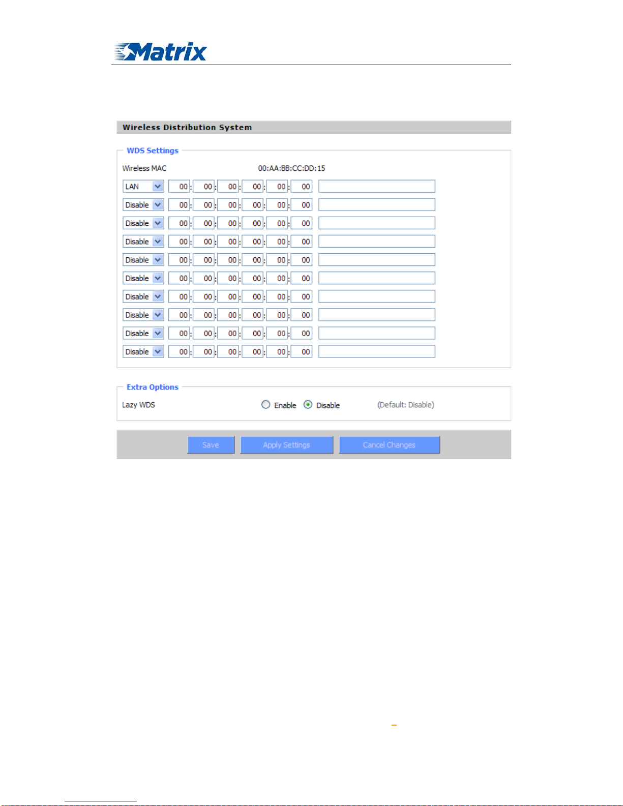
3.3.2.5 WDS
WDS (Wireless Distribution System) is a Wireless Access Point mode that ena bles wireless
bridging in which WDS APs communicate only with each other only (without allowing for
Page 40
MTX-ROUTER User Manual
Matrix Electronica S.L Page 40 of 87
Add: Alejandro Sanchez 109, 28019 Ma dr id. ESPAÑA
http://www.mtx-terminals.com Tel:+34-91.560.27.37 Fax:+34+34-91.565.28.65
wireless clients or stations to access them), and/or wireless repeating in which APs communicate
both with each other and with wireless stations (at the expense of half the throughput). This
firmware currently supports one types of WDS, LAN.
LAN-type WDS
This is the easiest, and currently most common, type of WDS used for linking LANs. It is
very simple to setup and requires no extra routing protocols or knowledge of networking. Simply
put, it is pure bridging. A simple example would be extending the range of an existing AP by
setting up a 2nd AP and connecting it to the first using LAN-type WDS.
1. Make sure you are using the same Wireless Settings on both routers and not any type of
Wireless Security.
2. Find a drop-down selection that has Disabled displayed. Click this and select LAN, do the same
on the other router.
3. On the first router, take the numbers next to Wireless MAC and enter them in to the second
router on the same line that you set to "LAN".
4. Take the Wireless MAC from the second router and enter them on the first router.
5. Check for any typing errors and then click Save Settings.
6. Go to the Wireless Status page. You should see WDS Link and the Wireless MAC of the other
router listed, with a signal reading. If the signal is "0dBm" then there may be something wrong.
Page 41

MTX-ROUTER User Manual
Matrix Electronica S.L Page 41 of 87
Add: Alejandro Sanchez 109, 28019 Ma dr id. ESPAÑA
http://www.mtx-terminals.com Tel:+34-91.560.27.37 Fax:+34+34-91.565.28.65
Check your antenna connections and configuration settings, and try again.
7. Once you have a good signal (-70dBm to -30dBm, -70dBm being lowest), you can change the
Internet Connection Type on the Basic Setup page of the second router to Disabled and set the
Gateway to the LAN IP Address of the first router. You can now run normal tests to check if you
are connected (like ping).
Lzay WDS: Default is disabled.
Note:WDS is only available in AP mode. Also Wireless encryption WPA2 and Wireless network
mode B-Only are not supported under WDS.
3.3.3 Services
3.3.3.1 Services
DHCP Client
Set Vendorclass: the DHCP server can automatically identify the specific identifier of the
computer running certain operating systems to send, such as the DHCP server can identify the
DHCP client running the operating systerm is Windows 2000 or Windows 98.
Identification identifier DHCP option can be assigned to DHCP clients based on specific operating
system.
Request IP: IP address of the request
DHCP Server
DHCPd assigns IP addresses to users local devices. While the main configuration is on the setup
page users can program some nifty special functions here.
Page 42

MTX-ROUTER User Manual
Matrix Electronica S.L Page 42 of 87
Add: Alejandro Sanchez 109, 28019 Ma dr id. ESPAÑA
http://www.mtx-terminals.com Tel:+34-91.560.27.37 Fax:+34+34-91.565.28.65
Use NVRAM for client lease DB: users can store data to the system NVRAM area is enabled
Used domain: users can select here which domain the DHCP clients should get as their local
domain. This can be the WAN domain set on the Setup screen or the LAN domain which can be
set here.
LAN Domain: users can define here their local LAN domain which is used as local domain for
DNSmasq and DHCP service if chose above.
Static Leases: if users want to assign certain hosts a specific address then they can define them
here. This is also the way to add hosts with a fixed address to the router's local DNS service
(DNSmasq).
Additional DHCPd Options: some extra options users can set by entering them
DNSMasq
DNSmasq is a local DNS server. It will resolve all host names known to the router from dhcp
(dynamic and static) as well as forwarding and caching DNS entries from remote DNS servers.
Local DNS enables DHCP clients on the LAN to resolve static and dynamic DHCP hostnames.
Local DNS: enables DHCP clients on the LAN to resolve static and dynamic DHCP hostnames
No DNS Rebind: when enabled, it can prevent an external attacker to access the router's internal
Web interface. It is a security measure
Page 43

MTX-ROUTER User Manual
Matrix Electronica S.L Page 43 of 87
Add: Alejandro Sanchez 109, 28019 Ma dr id. ESPAÑA
http://www.mtx-terminals.com Tel:+34-91.560.27.37 Fax:+34+34-91.565.28.65
Additional DNSMasq Options: some extra options users can set by entering them in Additional
DNS Options.
For example:
static allocation: dhcp-host=AB:CD:EF:11:22:33,192.168.0.10,myhost,myhost.domain,12h
max lease number: dhcp-lease-max=2
DHCP server IP range: dhcp-range=192.168.0.110,192.168.0.111,12h
SNMP
Location: equipment location
Contact: contact this equipment management
Name: device name
RO Community: SNMP RO community name, the default is public, Only to read.
RW Community: SNMP RW community name, the default is private, Read-write permissions
SSHD
Enabling SSHd allows users to access the Linux OS of their router with an SSH client
SSH TCP Forwarding: enable or disable to support the TCP forwarding
Password Login: allows login with the router password (username is admin)
Port: port number for SSHd (default is 22)
Authorized Keys: here users paste their public keys to enable key-based login (more secure than
a simple password)
System log
Enable Syslogd to capture system messages. By default they will be collected in the local file
/var/log/messages. To send them to another system, enter the IP address of a remote syslog server.
Page 44

MTX-ROUTER User Manual
Matrix Electronica S.L Page 44 of 87
Add: Alejandro Sanchez 109, 28019 Ma dr id. ESPAÑA
http://www.mtx-terminals.com Tel:+34-91.560.27.37 Fax:+34+34-91.565.28.65
Syslog Out Mode: two log mode
Net: the log information output to a syslog server
Console: the log information output to console port
Remote Server: if choose net mode, users should input a syslog server’s IP Address and run a
syslog server program on it.
Telnet
Telnet: enable a telnet server to connect to the router with telnet. The username is
admin and the
password is the router's password.
Note: If users use the router in an untrusted environment (for example as a public hotspot), it is
strongly recommended to use SSHd and deactivate telnet.
WAN Traffic Counter
Ttraff Daemon: enable or disable wan traffic counter function
3.3.3.2 PPPoE Server
PPPoE Server
RP-PPPoEServer Daemon: enable or disable PPPoE server
RP-PPPoEServer Options
Page 45

MTX-ROUTER User Manual
Matrix Electronica S.L Page 45 of 87
Add: Alejandro Sanchez 109, 28019 Ma dr id. ESPAÑA
http://www.mtx-terminals.com Tel:+34-91.560.27.37 Fax:+34+34-91.565.28.65
PPPOE Server Inferface: PPPoE server interface to the outside, only to support the LAN port
Client IP(s): IP range assigns to the PPPoE client in the format: xxx.xxx.xxx.xxx-xxx
Deflate Compression: enable or disable Deflate Compression
BSD Compression: enable or disable BSD Compression
LZS Stac Compression: enable or disable LZS Stac Compression
MPPC Compression: enable or disable MPPC Compression
MPPE PPPoE Encryption: enable or disable M PPE PPPoE Encryption
Session Limit per MAC: default is 10
LCP Echo Interval: time interval to set the the LCP calibration phase response
LCP Echo Failure: release PPPoE over failure times, the PPPoE client will need to reconnect
Idle Time: set idle time, idle time at the appropriate time to release the PPPoE
Authentication: including local and Radius (Remote Authentication Dial In User)
Local User Management
(CHAP Secrets)
User: set PPPOE client's user name
Password: set PPPOE client's user password
IP Addr ess: set PPPOE client's user IP address
Enable: enable or disable this setting
Radius
Page 46
MTX-ROUTER User Manual
Matrix Electronica S.L Page 46 of 87
Add: Alejandro Sanchez 109, 28019 Ma dr id. ESPAÑA
http://www.mtx-terminals.com Tel:+34-91.560.27.37 Fax:+34+34-91.565.28.65
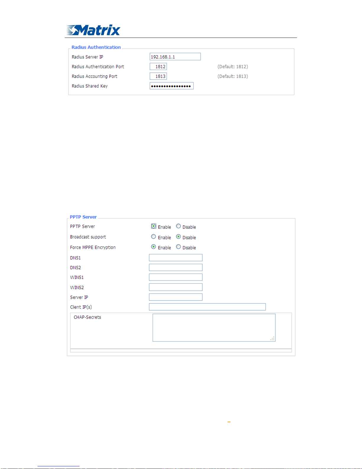
Radius Server IP: set the Remote Authentication Dial In User-Server IP
Radius Authentication Port: set the Remote Authentication Dial in User-Authenticati on Port
Radius Accounting Port: set the Remote Authentication Dial in User-Accounting Port
Radius Shared Key: transactions between the client and RADIUS accounting server are
authenticated through the use of a shared secret, which is never sent over the network.
3.3.4 VPN
3.3.4.1 PPTP
PPTP Server
Broadcast support: enable or disable broadcast support of PPTP server
Force MPPE Encryption: enable of disable force MPPE encryption of PPTP data
DNS1/DNS2/WINS1/WINS2: set DNS1/DNS2/WINS1/WINS2
Server IP: input IP address of the router as PPTP server, differ from LAN address
Client IP(s): IP address assigns to the client, the format is xxx.xxx.xxx.xxx-xxx
CHAP Secrets: user name and password of the client using PPTP service
Page 47
MTX-ROUTER User Manual
Matrix Electronica S.L Page 47 of 87
Add: Alejandro Sanchez 109, 28019 Ma dr id. ESPAÑA
http://www.mtx-terminals.com Tel:+34-91.560.27.37 Fax:+34+34-91.565.28.65
Note: client IP must be different with IP assigned by router DHCP.
The format of CHAP Secrets is user * password *.
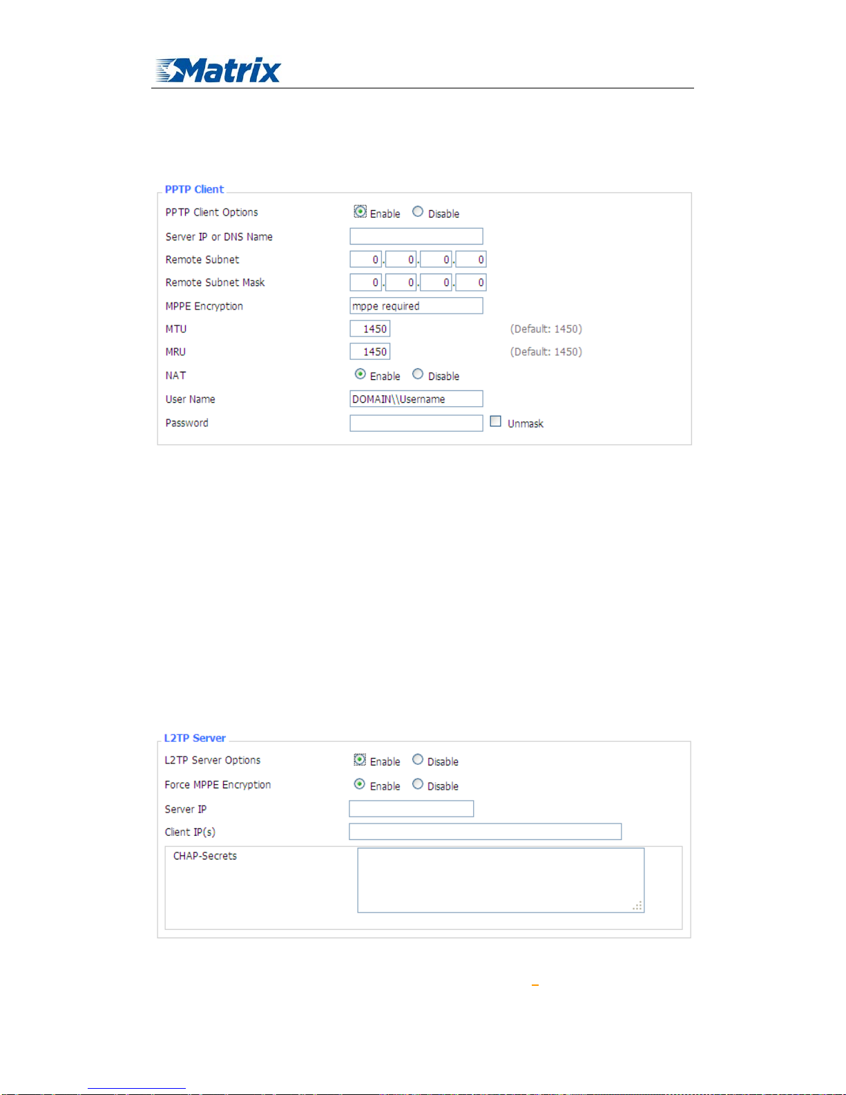
PPTP Client
Server IP or DNS Name: PPTP server’s IP Address or DNS Name
Remote Subnet: the network of the remote PPTP server
Remote Subnet Mask: subnet mask of remote PPTP server
MPPE Encryption: enable or disable Microsoft Point-to-Point Encryption。
MTU: maximum Transm ission Unit
MRU: maximum Receive Unit
NAT: network Address Translation
User Nam e: user nam e to login PPTP Server .
Password: password to log into PPTP Server.
3.3.4.2 L2TP
L2TP Server
Force MPPE Encryption: enable or disable force MPPE encryption of L2TP data
Page 48

MTX-ROUTER User Manual
Matrix Electronica S.L Page 48 of 87
Add: Alejandro Sanchez 109, 28019 Ma dr id. ESPAÑA
http://www.mtx-terminals.com Tel:+34-91.560.27.37 Fax:+34+34-91.565.28.65
Server IP: input IP address of the router as PPTP server, differ from LAN address
Client IP(s): IP address assigns to the client, the format is xxx.xxx.xxx.xxx-xxx.xxx.xxx.xxx
CHAP Secrets: user name and password of the client using L2TP service
Note: client IP must be different with IP assigned by router DHCP.
The format of CHAP Secrets is user * password *.
L2TP Client
Gateway(L2TP Server): L2TP server’s IP Address or DNS Name
Remote Subnet: the network of remote PPTP server
Remote Subnet Mask: subnet mask of remote PPTP server
MPPE Encryption: enable or disable Microsoft Point-to-Point Encryption
MTU: maximum transmission unit
MRU: maximum receive unit
NAT: network address translation
User Name: user name to login L2TP Server
Password: password to login L2TP Server
Require CHAP: enable or disable support chap authentication protocol
Refuse PAP: enable or disable refuse to support the pap authentication
Require Authentication: enable or disable support authentication protocol
3.3.4.3 OPENVPN
OPENVPN Server
Start Type: WAN UP----start after on-line, System----start when boot up
Page 49

MTX-ROUTER User Manual
Matrix Electronica S.L Page 49 of 87
Add: Alejandro Sanchez 109, 28019 Ma dr id. ESPAÑA
http://www.mtx-terminals.com Tel:+34-91.560.27.37 Fax:+34+34-91.565.28.65
Config via: GUI----Page configuration, Config File----config File configuration
Server mode: Router (TUN)-route mode, Bridge (TAP)----bridge mode
Router (TUN):
Network: network address allowed by OPENVPN server
Netmask: netmask allowed by OPENVPN server
Bridge (TAP):
DHCP-Proxy mode: enable or disable DHCP-Proxy mode
Pool start IP: pool start IP of the client allowed by OPENVPN server
Pool end IP: pool end IP of the client allowed by OPENVPN server
Gateway: the gateway of the client allowed by OPENVPN server
Netmask: netmask of the client allowed by OPENVPN server
Port: listen port of OPENVPN server
Tunnel Protocol: UCP or TCP of OPENVPN tunnel protocol
Encryption Cipher: Blowfish CBC,AES-128 CBC,AES-192 CBC,AES-256 CBC,AES-512
CBC
Hash Algorithm: Hash algorithm provides a method of quick access to data, including SHA1,
SHA256,SHA512,MD5
Advanced Options
Page 50

MTX-ROUTER User Manual
Matrix Electronica S.L Page 50 of 87
Add: Alejandro Sanchez 109, 28019 Ma dr id. ESPAÑA
http://www.mtx-terminals.com Tel:+34-91.560.27.37 Fax:+34+34-91.565.28.65
Use LZO Compression: enable or disable use LZO compression for data transfer
Redirect default Gateway: enable or disable redirect default gateway
Allow Client to Client: enable or disable allow client to client
Allow duplicate cn: enable or disable allow duplicate cn
TUN MTU Setting: set the value of TUN MTU
TCP MSS: MSS of TCP data
TLS Cipher: TLS (Transport Layer Security) encryption standard supports AES-128 SHA and
AES-256 SHA
Client connect script: define some client script by user self
CA Cert: CA certificate
Public Server Cert: server certificate
Private Server Key: the key seted by the server
DH PEM: PEM of the server
Page 51

MTX-ROUTER User Manual
Matrix Electronica S.L Page 51 of 87
Add: Alejandro Sanchez 109, 28019 Ma dr id. ESPAÑA
http://www.mtx-terminals.com Tel:+34-91.560.27.37 Fax:+34+34-91.565.28.65
Additional Config: additional configurations of the server
CCD-Dir DEFA ULT file: other file approaches
TLS Auth Key: authority key of Transport Layer Security
Certificate Revoke List: configure some revoke certificates
OPENVPN Client
Server IP/Name: IP address or domain name of OPENVPN server
Port: listen port of OPENVPN client
Tunnel Device: TUN----Router mode, TAP----Bridge mode
Tunnel Protocol: UDP and TCP protocol
Encryption Cipher: Blowfish CBC,AES-128 CBC,AES-192 CBC,AES-256 CBC,AES-512
CBC
Hash Algorithm: Hash algorithm provides a method of quick access to data, including SHA1,
SHA256, SHA512, MD5
nsCertType verification: support ns certificate type
Page 52

MTX-ROUTER User Manual
Matrix Electronica S.L Page 52 of 87
Add: Alejandro Sanchez 109, 28019 Ma dr id. ESPAÑA
http://www.mtx-terminals.com Tel:+34-91.560.27.37 Fax:+34+34-91.565.28.65
Use LZO Compression: enable or disable use LZO compression for data transfer
NAT: enable or disable NAT through function
Bridge TAP to br0: enable or disable bridge TAP to br0
Local IP Address: set IP address of local OPENVPN client
TUN MTU Setting: set MTU value of the tunnel
TCP MSS: mss of TCP data
TLS Cipher: TLS (Transport Layer Security) encryption standard supports AES-128 SHA an d
AES-256 SHA
TLS Auth Key: authority key of Transport Layer Security
Additional Config: additional configurations of OPENVPN server
Policy based Routing: input some defined routing policy
CA Cert: CA certificate
Public Client Cert: client certificate
Private Client Key: client key
Page 53

MTX-ROUTER User Manual
Matrix Electronica S.L Page 53 of 87
Add: Alejandro Sanchez 109, 28019 Ma dr id. ESPAÑA
http://www.mtx-terminals.com Tel:+34-91.560.27.37 Fax:+34+34-91.565.28.65
3.3.4.4 IPSEC
Connect Status and Control
Show IPSEC connection and status of current router on IPSEC page.
Name: the name of IPSEC connection
Type: The type and function of current IPSEC connection
Common name: local subnet, local address, opposite end address and opposite end subnet of
current connection
Status: connection status: closed, negotiating, establish
Closed: this connection does not launch a connection request to opposite end
Negotiating: this connection launch a request to opposite end, is under negotiating, the
connection has not been established yet
Establish: the connection has been established, enabled to use this tunnel
Action: the action of this connection, current is to delete, edit, reconnect and enable
Delete: to delete the connection, also will delete IPSEC if IPSEC has set up
Edit: to edit the configure information of this connection, reload this connection to make
the configuration effect after edit
Reconnect: this action will remove current tunnel, and re-launch tunnel establish request
Enable: when the connection is enable, it will launch tunnel establish request when the
system reboot or reconnect, otherwise the connection will not do it
Add: to add a new IPSEC connection
Add IPSEC connection or edit IPSEC connection
Type: to choose IPSEC mode and relevant functions in this part, supports tunnel mode client,
tunnel mode server and transfer mode currently
Connection: this part contains basic address information of the tunnel
Page 54

MTX-ROUTER User Manual
Matrix Electronica S.L Page 54 of 87
Add: Alejandro Sanchez 109, 28019 Ma dr id. ESPAÑA
http://www.mtx-terminals.com Tel:+34-91.560.27.37 Fax:+34+34-91.565.28.65
Name: to indicate this connection name, must be unique
Enabled: If enable, the connection will send tunnel connection request when it is reboot or
re-connection, otherwise it is no need if disable
Local WAN Interface: local addresss of the tunnel
Remote Host Address: IP/domain name of end opposite; this option can not fill in if using tunnel
mode server
Local Subnet: IPSec local protects subnet and subnet mask, i.e. 192.168.1.0/24; this option can
not fill in if using transfer mode
Remote Subnet: IPSec opposite end protects subnet and subnet mask, i.e.192.168.7.0/24; this
option can not fill in if using transfer mode
Local ID: tunnel local end identification, IP and domain name are available
Remote ID: tunnel opposite end identification, IP and domain name are available
Detection: this part contains configure information of connection detection
Enable DPD Detection: enable or disable this function, tick means enable
Time Interval: set time interval of connect detection (DPD)
Timeout: set the timeout of connect detection
Action: set the action of connect detection
Advanced Settings: this part contains relevant setting of IKE, ESP, negotiation mode, etc.
Page 55

MTX-ROUTER User Manual
Matrix Electronica S.L Page 55 of 87
Add: Alejandro Sanchez 109, 28019 Ma dr id. ESPAÑA
http://www.mtx-terminals.com Tel:+34-91.560.27.37 Fax:+34+34-91.565.28.65
Enable Advanced Settings: enable to configure 1st and 2nd phase information, otherwise it
will automic negotiation according to opposite end
IKE Encryption: IKE phased encryption mode
IKE Integrity: IKE phased integrity solution
IKE Grouptype: DH exchange algorithm
IKE Lifetime: set IKE lifetime, current unit is hour, the default is 0
ESP Encry ptio n: ESP encryption type
ESP Integrity: ESP integrity solution
ESP Keylife: set ESP keylife, current unit is hour, the default is 0
IKE aggressive mode allowed: negotiation mode adopt aggressive mode if tick; it is main
mode if non-tick
Negotiate payload compress ion: Tick to enable PFS, non-tick to diable PFS
Authentication: choose use share encryption option or certificate authentication option. Current is
only to choose use share encryption option.
3.3.4.5 GRE
GRE (Generic Routing Encapsulation, Generic Routing Encapsulation) protocol is a network
layer protocol (such as IP and IPX) data packets are encapsulated, so these encapsulated data
packets to another network layer protocol (IP)transmission. GRE Tunnel (tunnel) technology,
Layer Two Tunneling Protocol V PN (V ir tual Private Network).
GRE Tunnel: enable or disable GRE function
Page 56

MTX-ROUTER User Manual
Matrix Electronica S.L Page 56 of 87
Add: Alejandro Sanchez 109, 28019 Ma dr id. ESPAÑA
http://www.mtx-terminals.com Tel:+34-91.560.27.37 Fax:+34+34-91.565.28.65
Number
:Switch on/off GRE tunnel app
Status
:Switch on/off someone GRE tunnel app
Name
:GRE tunnel name
Through
:The GRE packet transmit interface
Peer W an IP Addr
:The remote WAN address
Peer Subnet
:The remote gateway local subnet, eg: 192.168.1.0/24
Peer Tunnel IP
:The remote tunnel ip address
Local T unnel IP
:The local tunnel ip address
Local Netmask
:Netmask of local network
Keepalive
:Enable or disable GRE Keepalive function
Retry times
:GRE keepalive detect fail retries
Interval
:The time interval of GRE keepalive packet sent
Fail Action
:The action would be exec after keeping alive failed
Click on “View GRE tunnels” keys can view the information of GRE
3.3.5 Security
3.3.5.1 Firewall
Page 57

MTX-ROUTER User Manual
Matrix Electronica S.L Page 57 of 87
Add: Alejandro Sanchez 109, 28019 Ma dr id. ESPAÑA
http://www.mtx-terminals.com Tel:+34-91.560.27.37 Fax:+34+34-91.565.28.65
You can enable or disable the firewall, filter specific Internet data types,and prevent
anonymous Internet requests,ultimately enhance network security.
Firewall Protection
Firewall enhance network security and use SPI to check the packets into the network.To use
firewall protection, choose to enable otherwise disabled. Only enable the SPI firewall, you can use
other firewall functions: filtering proxy, block WAN requests, etc.
Additional Filters
Filter Proxy: Wan proxy server may reduce the security of the gateway, Filtering Proxy will
refuse any access to any wan proxy server.
Click the check box to enable the function otherwise
disabled.
Filter Cookies: Cookies are the website of data the data stored on your computer.When you interact
with the site ,the cookies will be used. Click the check box to enable the function otherwise
disabled.
Filter Java Applets: If refuse to Java, you may not be able to open web pages using the Java
programming.. Click the check box to enable the function otherwise disabled.
Filter ActiveX: If refuse to ActiveX, you may not be able to open web pages using the ActiveX
programming. Click the check box to enable the function otherwise disabled.
Prevent WAN Request
Block Anonymous WAN Requests (ping): By selecting “Block Anonymous WAN Requests
(ping)” box to enable this feature, you can prevent your network from the Ping or detection of
other Internet users. so that make More difficult to break into your network.
The default state of
this feature is enabled ,choose to disable allow anonymous Internet requests.
Filter IDENT (Port 113): Enable this feature can prevent port 113 from being scaned from
outside. Click the check box to enable the function otherwise disabled.
Block WAN SNMP access: This feature prevents the SNMP connection requests from the WAN.
After Complete the changes, click the Save Settings button to save your changes. Click the
Cancel Changes button to cancel unsaved changes.
Page 58

MTX-ROUTER User Manual
Matrix Electronica S.L Page 58 of 87
Add: Alejandro Sanchez 109, 28019 Ma dr id. ESPAÑA
http://www.mtx-terminals.com Tel:+34-91.560.27.37 Fax:+34+34-91.565.28.65
Impede WAN DoS/Bruteforce
Limit ssh Access: This feature limits the access request from the WAN by ssh, and per minute up
to accept two connection requests on the same IP. Any new access request will be automatically
dropped.
Limit Telnet Access: This feature limits the access request from the WAN by Telnet, and per
minute up to accept two connection requests on the same IP. Any new access request will be
automatically dropped.
Limit PPTP Server Access: When build a PPTP Server in the router,this feature limits the access
request from the WAN by ssh, and per minute up to accept two connection requests on the same
IP . Any new access request will be automatically dropped.
Limit L2TP Server Access: When build a L2TP Server in the router, this feat ure limits the access
request from the WAN by ssh, and per minute up to accept two connection requests on the same IP.
Any new access request will be automatically dropped.
Log Management
The router can keep logs of all incoming or outgoing traffic for your Internet connection.
Log: To keep activity logs, select Enable. To stop logging, select Disable. When select enable, the
following page will appear.
Log Level: Set this to the required log level. Set Log Level higher to log more actions.
Options: When select Enable, the corresponding connection will be recorded in the journal, the
disabled are not recorded.
Incoming Log: To see a temporary log of the Router's most recent incoming traffic, click the
Incoming Log button.
Page 59

MTX-ROUTER User Manual
Matrix Electronica S.L Page 59 of 87
Add: Alejandro Sanchez 109, 28019 Ma dr id. ESPAÑA
http://www.mtx-terminals.com Tel:+34-91.560.27.37 Fax:+34+34-91.565.28.65
Outgoing Log: To see a temporary log of the Router's most recent outgoing traffic, click the
Outgoing Log button.
Click the Save Settings button to save your changes. Click the Cancel Changes button to cancel
unsaved changes.
3.3.5.2 VPN Passthrough
Virtual Private Networking (VPN) is typically used for work-related networking. For VPN tunnels,
the router supports OPENVPN Passthrough, PPTP Passthrough and L2TP Passthrough.
IPSec Passthrough
:Internet Protocol Security (IPSec) is a suite of protocols used to implement
secure exchange of packets at the IP layer. To allow IPSec tunnels to pass through the router,
IPSec Passthrough is enabled by default. To disable IPSec Passthrough, select Disable.
PPTP Passthrough
:Point-to-Point Tunneling Protocol is the method used to enable VPN sessions
to a Windows NT 4.0 or 2000 server. To allow PPTP tunnels to pass through the router, PPTP
Passthrough is enabled by default. To disable PPTP Passthrough, select Disable.
L2TP Passthrough
:Layer Two (2) Tunneling Protocol, an extension to the PPP protocol that
enables ISPs to operate Virtual Private Networks (VPNs). L2TP merges the best features of two
other tunneling protocols: PPTP from Microsoft and L2F from Cisco Systems. To allow L2TP
tunnels to pass through the router, L2TP Passthrough is enabled by default. To disable L2TP
Passthrough, select Disable.
Click the Save Settings button to save your changes. Click the Cancel Changes button to cancel
Page 60
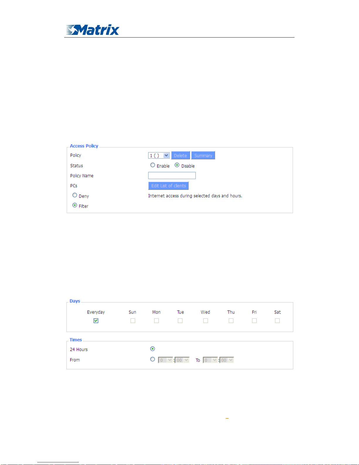
MTX-ROUTER User Manual
Matrix Electronica S.L Page 60 of 87
Add: Alejandro Sanchez 109, 28019 Ma dr id. ESPAÑA
http://www.mtx-terminals.com Tel:+34-91.560.27.37 Fax:+34+34-91.565.28.65
unsaved changes.
3.3.6 Access Restrictions
3.3.6.1 W AN Access
Use access restrictions, you can block or allow specific types of Internet applications. You can
set specific PC-based Internet access policies. This feature allows you to customize up to ten
different Internet Access Policies for particular PCs, which are identified by their IP or MAC
addresses.
Two options in the default policy rules: "Filter" and "reject". If select "Deny”, you will deny
specific computers to access any Internet service at a particular time period. If you choose to "filter",
It will block specific computers to access the specific sites at a specific time period. You can set up
10 Internet access policies filtering specific PCs access Internet services at a particular time period.
Access Policy: You may define up to 10 access policies. Click Delete to delete a policy or Summary
to see a summary of the policy.
Status: Enable or disable a policy.
Policy Name: You may assign a name to your policy.
PCs: The part is used to edit client list, the strategy is only effective for the PC in the list.
Days: Choose the day of the week you would like your policy to be applied.
Times: Enter the time of the day you would like your policy to be applied.
Page 61

MTX-ROUTER User Manual
Matrix Electronica S.L Page 61 of 87
Add: Alejandro Sanchez 109, 28019 Ma dr id. ESPAÑA
http://www.mtx-terminals.com Tel:+34-91.560.27.37 Fax:+34+34-91.565.28.65
Website Blocking by URL Address: You can block access to certain websites by entering their
URL.
Website Blocking by Keyword: You can block access to certain website by the keywords
contained in their webpage
set up Internet access policy
1. Select the policy number (1-10) in the drop-down menu.
Page 62

MTX-ROUTER User Manual
Matrix Electronica S.L Page 62 of 87
Add: Alejandro Sanchez 109, 28019 Ma dr id. ESPAÑA
http://www.mtx-terminals.com Tel:+34-91.560.27.37 Fax:+34+34-91.565.28.65
2. For this policy is enabled, click the radio button next to "Enable"
3. Enter a name in the Policy Name field.
4. Click the Edit List of PCs button.
5. On the List of PCs screen, specify PCs by IP address or MAC address. Enter the appropriate IP
addresses into the IP fields. If you have a range of IP addresses to filter, complete the
appropriate IP Range fields. Enter the appropriate MAC addresses into the MAC fields.
6. Click the Apply button to save your changes. Click the Cancel button to cancel your unsaved
changes. Click the Close button to return to the Filters screen.
7. If you want to block the listed PCs from Internet access during the designated days and time,
then keep the default setting, Deny. If you want the listed PCs to have Internet filtered during
the designated days and time, then click the radio button next to Filter.
8. Set the days when access will be filtered. Select Everyday or the appropriate days of the week.
9. Set the time when access will be filtered. Select 24 Hours, or check the box next to From and
use the drop-down boxes to designate a specific time period.
10. Click the Add to Policy button to save your changes and active it.
11. To create or edit additional policies, repeat steps 1-9.
12. To delete an Internet Access Policy, select the policy number, and click the Delete button.
Note:
1) The default factory value of policy rules is "filtered". If the user chooses the default policy
rules for "refuse", and editing strategies to save or directly to save the settings. If the
strategy edited is the first, it will be automatically saved into the second, if not the first,
keep the original number.
2) Turn off the power of the router or reboot the router can cause a temporary failure。After the
failure of the router, if can not automatically synchronized NTP time server, you need to
recalibrate to ensure the correct implementation of the relevant period control function.
3.3.6.2 Packet Filt e r
To block some packets getting Internet access or block some Internet packets getting local
network access, you can configure filter items to block these packets.
Packet Filter
Packet filter function is realized based on IP address or port of packets.
Enable Packet Filter: Enable or disable “packet filter” function
Policy: The filter rule’s policy, you can choose the following options
Discard The Following--Discard packets conform to the following rules, Accept all other
packets
Only Accept The Following-- Accept only the data packets conform to the following rules,
Discard all other packets
Page 63

MTX-ROUTER User Manual
Matrix Electronica S.L Page 63 of 87
Add: Alejandro Sanchez 109, 28019 Ma dr id. ESPAÑA
http://www.mtx-terminals.com Tel:+34-91.560.27.37 Fax:+34+34-91.565.28.65
Direction
input: packet from WAN to LAN
output: packet from LAN to WAN
Protocol: packet protocol type
Source Ports: packet's source port
Destination Ports: packet's destination port
Source IP: packet's source IP address
Destination IP: packet's destination IP address
Note: "Source Port" ,"Destination P o rt" ,"S o ur c e IP " ,"Destination IP" could not be all empty ,you
have to input at least one of these four parameters.
3.3.7 NAT
3.3.7.1 Port Forward in g
Port Forwarding allows you to set up public services on your network, such as web servers,
ftp servers, e-mail servers, or other specialized Internet applications. Specialized Internet
applications are any applications that use Internet access to perform functions such as
videoconferencing or online gaming. When users send this type of request to your network via the
Internet, the router will forward those requests to the appropriate PC. If you want to forward a
whole range of ports, see
Port Range Forwarding.
Page 64

MTX-ROUTER User Manual
Matrix Electronica S.L Page 64 of 87
Add: Alejandro Sanchez 109, 28019 Ma dr id. ESPAÑA
http://www.mtx-terminals.com Tel:+34-91.560.27.37 Fax:+34+34-91.565.28.65
Application: Enter the name of the application in the field provided.
Protocol: Chose the right protocol TCP,UDP or Both. Set this to what the application requires.
Source Net: Forward only if sender matches this ip/net (example 192.168.1.0/24).
Port from: Enter the number of the external port (the port number seen by users on the Internet).
IP Address: Enter the IP Address of the PC running the application.
Port to: Enter the number of the internal port (the port number used by the application).
Enable: Click the Enable checkbox to enable port forwarding for the application.
Check all values and click Save Settings to save your settings. Click the Cancel changes
button to cancel your unsaved changes.
3.3.7.2 Port Range Forward
Port Range Forwarding allows you to set up public services on your network, such as web
servers, ftp servers, e-mail servers, or other specialized Internet applications. Specialized Internet
applications are any applications that use Internet access to perform functions such as
videoconferencing or online gaming. When users send this type of request to your network via the
Internet, the router will forward those requests to the appropriate PC. If you only want to forward
a single port, see
Port Forwarding.
Application: Enter the name of the application in the field provided.
Start:Enter the number of the first port of the range you want to seen by users on the Internet and
forwarded to your PC.
End: Enter the number of the last port of the range you want to seen by users on the Internet and
forwarded to your PC.
Protocol: Chose the right protocol TCP,UDP or Both. Set this to what the application requires.
IP Address: Enter the IP Address of the PC running the application.
Enable: Click the Enable checkbox to enable port forwarding for the application.
Check all values and click Save Settings to save your settings. Click the Cancel changes
button to cancel your unsaved changes.
3.3.7.3 Port Triggering
Port Triggering allows you to do port forwarding without setting a fixed PC. By setting Port
Triggering rules, you can allow inbound traffic to arrive at a specific LAN host, using ports
different than those used for the outbound traffic. This is called port triggering since the outbound
traffic triggers to which ports inbound traffic is directed.
Page 65

MTX-ROUTER User Manual
Matrix Electronica S.L Page 65 of 87
Add: Alejandro Sanchez 109, 28019 Ma dr id. ESPAÑA
http://www.mtx-terminals.com Tel:+34-91.560.27.37 Fax:+34+34-91.565.28.65
If you want to forward ports to a PC with a static IP address, see
Port Forwarding or Port
Range Forwarding.
Application: Enter the name of the application in the field provided.
Triggered Port Range: Enter the number of the first and the last port of the range, which should
be triggered. If a PC sends outbound traffic from those ports, incoming traffic on the Forwarded
Range will be forwarded to that PC.
Forwarded Port Range: Enter the number of the first and the last port of the range, which should
be forwarded from the Internet to the PC, which has triggered the Triggered Range.
Enable :Click the Enable checkbox to enable port triggering for the application.
Check all values and click Save Settings to save your settings. Click the Cancel changes
button to cancel your unsaved changes.
3.3.7.4 DMZ
The DMZ (DeMilitarized Zone) hosting feature allows one local user to be exposed to the
Internet for use of a special-purpose service such as Internet gaming or videoconferencing. DMZ
hosting forwards all the ports at the same time to one PC. The Port Forwarding feature is more
secure because it only opens the ports you want to have opened, while DMZ hosting opens all the
ports of one computer, exposing the computer so the Internet can see it.
Any PC whose port is being forwarded must should have a new static IP address assigned to
it because its IP address may change when using the DHCP function.
DMZ Host IP Address: To expose one PC to the Internet, select Enable and enter the computer's
IP address in the DMZ Host IP Address field. To disa ble the DMZ, keep the default setting:
Disable
Check all values and click Save Settings to save your settings. Click the Cancel changes
button to cancel your unsaved changes.
Page 66

MTX-ROUTER User Manual
Matrix Electronica S.L Page 66 of 87
Add: Alejandro Sanchez 109, 28019 Ma dr id. ESPAÑA
http://www.mtx-terminals.com Tel:+34-91.560.27.37 Fax:+34+34-91.565.28.65
3.3.8 QoS Setting
3.3.8.1 Basic
Bandwidth management prioritizes the traffic on your router. Interactive traffic (telephony,
browsing, telnet, etc.) gets priority and bulk traffic (file transfer, P2P) gets low priority. The main
goal is to allow both types to live side-by side without unimportant traffic disturbing more critical
things. All of this is more or less automatic.
QoS allows control of the bandwidth allocation to different services, netmasks, MAC
addresses and the four LAN ports.
Uplink (kbps)
:In order to use bandwidth management (QoS) you must enter bandwidth values
for your uplink. These are generally 80% to 90% of your maximum bandwidth.
Downlink (kbps)
:In order to use bandwidth management (QoS) you must enter bandwidth values
for your downlink. These are generally 80% to 90% of your maximum bandwidth.
3.3.8.2 Classify
Netmask Priority
Page 67

MTX-ROUTER User Manual
Matrix Electronica S.L Page 67 of 87
Add: Alejandro Sanchez 109, 28019 Ma dr id. ESPAÑA
http://www.mtx-terminals.com Tel:+34-91.560.27.37 Fax:+34+34-91.565.28.65
You may specify priority for all traffic from a given IP address or IP Range.
Check all values and click Save Settings to save your settings. Click the Cancel changes button
to cancel your unsaved changes.
3.3.9 Applications
3.3.9.1 Serial Applications
There is a console port on MTX-ROUTER. Normally, this port is used to debug the router. This
port can also be used as a serial port. The router has embedded a serial to TCP program. The data
sent to the serial port is encapsulated by TCP/IP protocol stack and then is sent to the destination
server. This function can work as a DTU (Data Terminal Unit). Please refer
www.mtx-terminals.com for more information about this product.
Baudrate: The serial port’s baudrate
Databit: The serial port’s databit
Parity: The serial port’s parity
Stopbit: The serial port’s stopbit
Flow Control: The serial port’s flow control type.
Enable Serial TCP Function: Enable the serial to TCP function
Protocol Type: The protocol type to transmit data.
UDP(DTU) – Data transmit with UDP protocol , work as a DTU which has
application protocol and hear beat mechanism.
Page 68

MTX-ROUTER User Manual
Matrix Electronica S.L Page 68 of 87
Add: Alejandro Sanchez 109, 28019 Ma dr id. ESPAÑA
http://www.mtx-terminals.com Tel:+34-91.560.27.37 Fax:+34+34-91.565.28.65
Pure UDP – Data transmit with standard UDP protocol.
TCP(DTU) -- Data transmit with TCP protocol , work as a DTU which has
application protocol and hear beat mechanism.
Pure TCP -- Data transmit with standard TCP protocol, router is the client.
TCP Server -- Data transmit with standard TCP protocol, router is the server.
TCST -- Data transmit with TCP protocol, Using a custom data
Server Address: The data service center’s IP Address or domain name.
Server Port: The data service center’s listening port.
Device ID: The router’s identity ID.
Device Number: The router’s phone number.
Heartbeat Interval: The time interval to send heart beat packet. This item is valid only
when you choose UDP(DTU) or TCP(DTU) protocol type.
TCP Server Listen Port: This item is valid when Protocol Type is “TCP Server”
Custom Heartbeat Packet : This item is valid when Protocol Type is “TCST”
Custom Registration Packets: This item is valid when Protocol Type is “TCST”
3.3.10 Administration
3.3.10.1 Management
The Management screen allows you to change the router's settings. On this page you will find
most of the configurable items of the router code.
The new password must not exceed 32 characters in length and must not include any spaces.
Enter the new password a second time to confirm it.
Note
:
Default username is admin.
It is strongly recommended that you change the factory default password of the router, which
is admin. All users who try to access the router's web-based utility or Setup Wizard will be
prompted for the router's password.
Web Access
This feature allows you to manage the router using either HTTP protocol or the HTTPS protocol.
If you choose to disable this feature, a manual reboot will be required.You can also activate or not
the router information web page. It's now possible to password protect this page (same username
and password than above).
Page 69

MTX-ROUTER User Manual
Matrix Electronica S.L Page 69 of 87
Add: Alejandro Sanchez 109, 28019 Ma dr id. ESPAÑA
http://www.mtx-terminals.com Tel:+34-91.560.27.37 Fax:+34+34-91.565.28.65
Protocol
:This feature allows you to manage the router using either HTTP protocol or the HTTPS
protocol
Auto-Refresh
:Adjusts the Web GUI automatic refresh interval. 0 disables this feature completely
Enable Info Site
:Enable or disable the login system information page
Info Site Password Protection
:Enable or disable the password protection feature of the system
information page
Remote Access
:This feature allows you to manage the router from a remote location, via the
Internet. To disable this feature, keep the default setting, Disable. To enable this feature, select
Enable, and use the specified port (default is 8080) on your PC to remotely manage the router. You
must also change the router's default password to one of your own, if you haven't already.
To remotely manage the router, enter http://xxx.xxx.xxx.xxx:8080 (the x's represent the router's
Internet IP address, and 8080 represents the specified port) in your web browser's address field.
You will be asked for the router's password.
If you use https you need to specify the url as https://xxx.xxx.xxx.xxx:8080 (not all firmwares
does support this without rebuilding with SSL support).
SSH Management:You can also enable SSH to remotely access the router by Secure Shell. Note
that SSH daemon needs to be enable in Services
page.
Note
:
If the Remote Router Access feature is enabled, anyone who knows the router's Internet IP
address and password will be able to alter the router's settings.
Telnet Management
:Enable or disable remote Telnet function
Page 70

MTX-ROUTER User Manual
Matrix Electronica S.L Page 70 of 87
Add: Alejandro Sanchez 109, 28019 Ma dr id. ESPAÑA
http://www.mtx-terminals.com Tel:+34-91.560.27.37 Fax:+34+34-91.565.28.65
Cron:The cron subsystem schedules execution of Linux commands. You'll need to use the
command line or startup scripts to actually use this.
802.1x
:A limited 802.1x server needed to fulfill WPA handshake requirements to allow Windows
XP clients to work with WPA.
Routing
:Routing enables the OSPF and RIP routing daemons if you have set up OSPF or RIP
routing in the Advanced Routing page.。
Language
:Set up the router page shows the type of language, including simplified Chinese and
English.
IP Filter Settings (adjust these for P2P)
:If you have any peer-to-peer (P2P) applications running
on your network please increase the maximum ports and lower the TCP/UDP timeouts. This is
necessary to maintain router stability because peer-to-peer applications open many connections
and don't close them properly. Consider using these:
Maximum Ports: 4096
TCP Tim eout: 3600 sec
UDP Tim eout: 120 sec
3.3.10.2 Keep Alive
Schedule Reboot
You can schedule regular reboots for the router :
Regularly after xxx seconds.
Page 71

MTX-ROUTER User Manual
Matrix Electronica S.L Page 71 of 87
Add: Alejandro Sanchez 109, 28019 Ma dr id. ESPAÑA
http://www.mtx-terminals.com Tel:+34-91.560.27.37 Fax:+34+34-91.565.28.65
At a specific date time each week or everyday.
Note
:
For date based reboots Cron must be activated. See Management for Cron activation.
3.3.10.3 Commands
Commands:You are able to run command lines directly via the Webinterface.
Run Command
:You can run command lines via the web interface. Fill the text area with your
command and click Run Commands to submit.
Startup
:You can save some command lines to be executed at startup's router. Fill the text area
with commands (only one command by row) and click Save Startup.
Shutdown
:You can save some command lines to be executed at shutdown's router. Fill the text
area with commands (only one command by row) and click Save Shutdown.
Firewall
:Each time the firewall is started, it can run some custom iptables instructions. Fill the
text area with firewall's instructions (only one command by row) and click Save Firewall.
Custom Script
:Custom script is stored in /tmp/custom.sh file. You can run it manually or use
cron to call it. Fill the text area with sc ript's instructions (only one command by row) and click
Save Custom Script.
3.3.10.4 Factory Defaults
Reset router settings:Click the Yes button to reset all configuration settings to their default
values. Then click the Apply Settings button.
Note
:
Any settings you have saved will be lost when the default settings are restored. After
restoring the router is accessible under the default IP address 192.168.1.2 and the default
password admin.
Page 72

MTX-ROUTER User Manual
Matrix Electronica S.L Page 72 of 87
Add: Alejandro Sanchez 109, 28019 Ma dr id. ESPAÑA
http://www.mtx-terminals.com Tel:+34-91.560.27.37 Fax:+34+34-91.565.28.65
3.3.10.5 Firmware Upgrade
Firmware Upgrade:New firmware versions are posted at ftp.matrix.es and can be downloaded.
If the Router is not experiencing difficulties, then there is no need to download a more recent
firmware version, unless that version has a new feature that you want to use.
Note
:
When you upgrade the Router's firmware, you lose its configuration settings, so make sure
you write down the Router settings before you upgrade its firmware.
To upgrade the Router's firmware:
1. Download the firmware upgrade file from the website.
2. Click the Browse... button and chose the firmware upgrade file.
3. Click the Upgrade button and wait until the upgrade is finished.
Note
:
Upgrading firmware may take a few minutes.
Do not turn off the power or press the reset button!
After flashing, reset to
:If you want to reset the router to the default settings for the firmware
version you are upgrading to, click the Firmware Defaults option.
3.3.10.6 Backup
Backup Settings
:You may backup your current configuration in case you need to reset the router
back to its factory default settings.Click the Backup button to backup your current configuration.
Page 73

MTX-ROUTER User Manual
Matrix Electronica S.L Page 73 of 87
Add: Alejandro Sanchez 109, 28019 Ma dr id. ESPAÑA
http://www.mtx-terminals.com Tel:+34-91.560.27.37 Fax:+34+34-91.565.28.65
Restore Settings:Click the Browse... button to browse for a configuration file that is currently
saved on your PC.Click the Restore button to overwrite all current configurations with the ones in
the configuration file.
Note
:
Only restore configurations with files backed up using the same firmware and the same
model of router.
3.3.11 Status
3.3.11.1 Router
Router Name: name of the router, settingbasic setting to modify
Router Model: model of the router, unavailable to modify
Firmware Version: software version information
MAC Address: MAC address of WAN, settingClone MAC Address to modify
Host Name: host name of the router, settingbasic setting to modify
WAN Domain Name: domain name of WAN, settingbasic setting to modify
LAN Domain Name: domain name of LAN, unavailable to modify
Current Time: local time of the system
Uptime: operating uptime as long as the system is powered on
Page 74

MTX-ROUTER User Manual
Matrix Electronica S.L Page 74 of 87
Add: Alejandro Sanchez 109, 28019 Ma dr id. ESPAÑA
http://www.mtx-terminals.com Tel:+34-91.560.27.37 Fax:+34+34-91.565.28.65
Total Available: the room for total available of RAM (that is physical memory minus some
reserve and the kernel of binary code bytes)
Free: free memory, the router will reboot if the memory is less than 500kB
Used: used memory, total available memory minus free memory
Buffers: used memory for buffers,
Cached: the memory used by high-speed cache memory
Active: active use of buffer or cache memory page file size
Inactive: not often used in a buffer or cache memory page file size
IP Filter Maximum Ports: preset is 4096, available to re-management
Active IP Connections: real time monitor active IP connections of the system, click to see the
table as blow:
Page 75

MTX-ROUTER User Manual
Matrix Electronica S.L Page 75 of 87
Add: Alejandro Sanchez 109, 28019 Ma dr id. ESPAÑA
http://www.mtx-terminals.com Tel:+34-91.560.27.37 Fax:+34+34-91.565.28.65
Active IP Connections: total active IP connections
Protocol: connection protocol
Timeouts: connection timeouts, unit is second
Source Address: source IP address
Remote Address: remote IP address
Service Name: connecting service port
Status: displayed status
3.3.11.2 WAN
Connection T ype: disabled, 3G/UMTS
Connection Uptime: connecting uptime; If disconnect, display Not available
Page 76

MTX-ROUTER User Manual
Matrix Electronica S.L Page 76 of 87
Add: Alejandro Sanchez 109, 28019 Ma dr id. ESPAÑA
http://www.mtx-terminals.com Tel:+34-91.560.27.37 Fax:+34+34-91.565.28.65
IP Addr ess: IP address of router WAN
Subnet Mask: subnet mask of router WAN
Gateway: the gateway of router WAN
DNS1, DNS2, DNS3: DNS1/DNS2/DNS3 of router WAN
Login Status: connection status of WAN
Disconnection: disconnect
Connection: connect
Module Ty pe: module type in 3G/UMTS way
Signal Status: signal intensity of the module in 3G/UMTS way
Network: network type of the module in 3G/UMTS way
Page 77

MTX-ROUTER User Manual
Matrix Electronica S.L Page 77 of 87
Add: Alejandro Sanchez 109, 28019 Ma dr id. ESPAÑA
http://www.mtx-terminals.com Tel:+34-91.560.27.37 Fax:+34+34-91.565.28.65
Total Flow: flow from power-off last time until now statistics, download and upload direction
Monthly Flow: the flow of a month, unit is MB
Last Month: the flow of last month
Next Month: the flow of next month
Backup: backup data administrat ion
Restore: restore data administration
Delete: delete data administration
3.3.11.3 LAN
Page 78

MTX-ROUTER User Manual
Matrix Electronica S.L Page 78 of 87
Add: Alejandro Sanchez 109, 28019 Ma dr id. ESPAÑA
http://www.mtx-terminals.com Tel:+34-91.560.27.37 Fax:+34+34-91.565.28.65
MAC Address: MAC Address of the LAN port ethernet
IP Addr ess: IP Address of the LAN port
Subnet Mask: Subnet Mask of the LAN port
Gateway: Gateway of the LAN port
Local DNS: DNS of the LAN port
Host Name: host name of LAN client
IP Addr ess: IP address of the client
MAC Address: MAC address of the client
Conn. Count: connection count caused by the client
Ratio: the ratio of 4096 connection
DNCP Server: enable or disable the router work as a DHCP server
DHCP Daemon: the agreement allocated using DHCP including DNSMasq and uDHCPd
Starting IP Address: the starting IP Address of the DHCP server’s Address pool
Ending IP Address: the ending IP Address of the DHCP server’s Address pool
Client Lease Time: the lease time of DHCP client
Host Name: host name of LAN client
Page 79

MTX-ROUTER User Manual
Matrix Electronica S.L Page 79 of 87
Add: Alejandro Sanchez 109, 28019 Ma dr id. ESPAÑA
http://www.mtx-terminals.com Tel:+34-91.560.27.37 Fax:+34+34-91.565.28.65
IP Addr ess: IP address of the client
MAC Address: MAC address of the client
Expires: the expiry the client rents the IP address
Interface: the interface assigned by dial-up system
User Name: user name of PPPoE client
Local IP: IP address assigned by PPPoE client
Delete: click to delete PPPoE client
Interface: the interface assigned by dial-up system
Local IP: tunnel IP address of local L2TP
Remote IP: tunnel IP address of L2TP server
Delete: click to disconnect L2TP
Interface: the interface assigned by dial-up system
User Name: user name of the client
Local IP: tunnel IP address of L2TP client
Remote IP: IP address of L2TP client
Delete: click to delete L2TP client
Interface: the interface assigned by dial-up system
Local IP: tunnel IP address of local PPTP
Remote IP: tunnel IP address of PPTP server
Delete: click to disconnect PPTP
Page 80

MTX-ROUTER User Manual
Matrix Electronica S.L Page 80 of 87
Add: Alejandro Sanchez 109, 28019 Ma dr id. ESPAÑA
http://www.mtx-terminals.com Tel:+34-91.560.27.37 Fax:+34+34-91.565.28.65
Interface: the interface assigned by dial-up system
User Name: user name of the client
Local IP: tunnel IP address of PPTP client
Remote IP: IP address of PPTP client
Delete: click to delete PPTP client
3.3.11.4 Wireless
MAC Address: MAC address of wireless client
Radio: display whether radio is on or not
Mode: wireless mode
Network: wireless network mode
SSID: wireless network name
Channel: wireless network channel
TX Power: reflection power of wireless network
Rate: reflection rate of wireless network
Encryption-Interface wl0: enable or diasbal Encryption-Interface wl0
PPTP Status: show wireless pptp status
Received (RX): received data packet
Transmitted (TX): transmitted data packet
Page 81

MTX-ROUTER User Manual
Matrix Electronica S.L Page 81 of 87
Add: Alejandro Sanchez 109, 28019 Ma dr id. ESPAÑA
http://www.mtx-terminals.com Tel:+34-91.560.27.37 Fax:+34+34-91.565.28.65
MAC Address: MAC address of wireless client
Interface: interface of wireless client
Uptime: connecting uptime of wireless client
TX Rate: transmit rate of wireless client
RX Rate: receive rate of wireless client
Signal: the signal of wireless client
Noise: the noise of wireless client
SNR: the signal to noise ratio of wireless client
Signal Quality: signal quality of wireless client
Neighbor's Wireless Network: display other networks nearby
SSID: the name of wireless network nearby
Mode: operating mode of wireless network nearby
MAC Address: MAC address of the wireless nearby
Channel: the channel of the wireless nearby
Rssi: signal intensity of the wireless nearby
Noise: the noise of the wireless nearby
Beacon: signal beacon of the wireless nearby
Open: the wireless nearby is open or not
Dtim: delivery traffic indication message of the wireless nearby
Rate: speed rate of the wireless nearby
Join Site: click to join wireless network nearby
3.3.11.5 Bandwidth
Page 82

MTX-ROUTER User Manual
Matrix Electronica S.L Page 82 of 87
Add: Alejandro Sanchez 109, 28019 Ma dr id. ESPAÑA
http://www.mtx-terminals.com Tel:+34-91.560.27.37 Fax:+34+34-91.565.28.65
Bandwidth Monitoring-LAN Graph
abscissa axis: time
vertical axis: speed rate
Bandwidth Monitoring-WAN Graph
abscissa axis: time
vertical axis: speed rate
Page 83

MTX-ROUTER User Manual
Matrix Electronica S.L Page 83 of 87
Add: Alejandro Sanchez 109, 28019 Ma dr id. ESPAÑA
http://www.mtx-terminals.com Tel:+34-91.560.27.37 Fax:+34+34-91.565.28.65
Bandwidth Monitoring-Wireless (W10) Graph
abscissa axis: time
vertical axis: speed rate
3.3.11.6 Sys-Info
Router Name: the name of the router
Router Model: the model of the router
LAN MAC: MAC address of LAN port
WAN MAC: MAC address of WAN port
Wireless MAC: MAC address of the wireless
WAN IP: IP address of WAN port
LAN IP: IP address of LAN port
Page 84

MTX-ROUTER User Manual
Matrix Electronica S.L Page 84 of 87
Add: Alejandro Sanchez 109, 28019 Ma dr id. ESPAÑA
http://www.mtx-terminals.com Tel:+34-91.560.27.37 Fax:+34+34-91.565.28.65
Radio: display whether radio is on or not
Mode: wireless mode
Network: wireless network mode
SSID: wireless network name
Channel: wireless network channel
TX Power: reflection power of wireless network
Rate: reflection rate of wireless network
Received (RX): received data packet
Transmitted (TX): transmitted data packet
MAC Address: MAC address of wireless client
Interface: interface of wireless client
Uptime: connecting uptime of wireless client
TX Rate: transmit rate of wireless client
RX Rate: receive rate of wireless client
Signal: the signal of wireless client
Noise: the noise of wireless client
SNR: the signal to noise ratio of wireless client
Signal Quality: signal quality of wireless client
Page 85

MTX-ROUTER User Manual
Matrix Electronica S.L Page 85 of 87
Add: Alejandro Sanchez 109, 28019 Ma dr id. ESPAÑA
http://www.mtx-terminals.com Tel:+34-91.560.27.37 Fax:+34+34-91.565.28.65
DHCP Server: enabled or disabled
ff-radauth: enabled or disabled
USB Support: enabled or disabled
Total Available: the room for total available of RAM (that is physical memory minus some
reserve and the kernel of binary code bytes)
Free: free memory, the router will reboot if the memory is less than 500kB
Used: used memory, total available memory minus free memory
Buffers: used memory for buffers, total available memory minus allocated memory
Cached: the memory used by high-speed cache memory
Active: Active use of buffer or cache memory page file size
Inactive: Not often used in a buffer or cache memory page file size
Host Name: host name of LAN client
IP Addr ess: IP address of the client
MAC Address: MAC address of he client
Expires: the expiry the client rents the IP address
Page 86
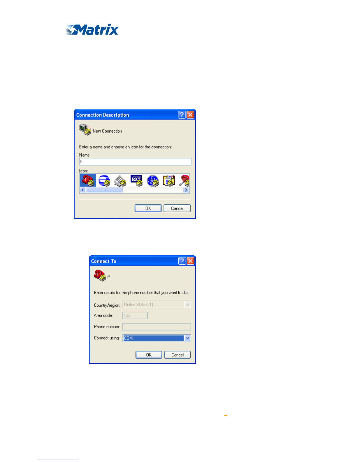
MTX-ROUTER User Manual
Matrix Electronica S.L Page 86 of 87
Add: Alejandro Sanchez 109, 28019 Ma dr id. ESPAÑA
http://www.mtx-terminals.com Tel:+34-91.560.27.37 Fax:+34+34-91.565.28.65
Chapter 4 Appendix
The following steps describe how to setup Windows XP Hyper Terminal.
1. Press “Start””Programs””Accessories””Communications””Hyper Terminal”
2. Input connection name, choose “OK”
3. Choose the correct COM port which connects to modem, choose “OK”
4. Configure the serial port parameters as following, choose “OK”
Bits per second: 115200
Data bits: 8
Page 87

MTX-ROUTER User Manual
Matrix Electronica S.L Page 87 of 87
Add: Alejandro Sanchez 109, 28019 Ma dr id. ESPAÑA
http://www.mtx-terminals.com Tel:+34-91.560.27.37 Fax:+34+34-91.565.28.65
Parity: None
Stop bits: 1
Flow control: None
5. Complete Hyper Terminal operation, It runs as following
 Loading...