

Page 1

MD-S70 MEDICAL LEG PRESS
Page 2

2
Page 3

IMPORTANT SAFETY INFORMATION
It is the sole responsibility of the purchaser
of MATRIX products to instruct all individuals,
whether they are the end user or supervising
personnel on proper usage of the equipment.
It is recommended that all users of MATRIX
exercise equipment be informed of the
following information prior to its use.
Do not use any equipment in any way other than as
designed or intended by the manufacturer. It is imperative
that MATRIX equipment be used properly to avoid injury.
INSTALLATION
1. STABLE AND LEVEL SURFACE: MATRIX exercise equipment
must be installed on a stable base and properly leveled.
2. SECURING EQUIPMENT: Manufacturer recommends
that all stationary MATRIX strength equipment
be secured to the oor to stabilize equipment
and eliminate rocking or tipping over. This
must be performed by a licensed contractor.
3. Under no circumstances should you slide equipment
across the oor due to risk of tipping. Use proper
materials handling techniques and equipment
recommended by OSHA.
All anchor points must be able to withstand
750 lbs. (3.3 kN) pull-out force.
MAINTENANCE
1. DO NOT use any equipment that is damaged and or
has worn or broken parts. Use only replacement parts
supplied by your country’s local MATRIX dealer.
2. MAINTAIN LABELS AND NAMEPLATES: Do not
remove labels for any reason. They contain
important information. If unreadable or missing,
contact your MATRIX dealer for a replacement.
3. MAINTAIN ALL EQUIPMENT: Preventative maintenance
is the key to smooth operating equipment as well
as keeping your liability to a minimum. Equipment
needs to be inspected at regular intervals.
4. Ensure that any person(s) making adjustments
or performing maintenance or repair of any
kind is qualied to do so. MATRIX dealers will
provide service and maintenance training at
our corporate facility upon request.
ADDITIONAL NOTES
This equipment should only be used in supervised areas
where access and control is specically regulated by the
owner. It is up to the owner to determine who is allowed
access to this training equipment. The owner should
consider a user’s: degree of reliability, age, experience, etc.
This training equipment meets industry standards for
stability when used for its intended purpose in accordance
with the instructions provided by the manufacturer.
This equipment is for indoor use only. This training equipment
is a Class S product (designed for use in a commercial
environment such as a tness facility). This training equipment
is in compliance with EN ISO 20957-1 and EN 957-2.
This equipment has been designed for medical/therapeutic
use when used under the supervision of a doctor or clinician.
NOTE
1. Ambient temperature for operating this equipment is 5°C
- 40°C (with NO air-ow), nominal 25°C.
2. Relative Humidity for operating this equipment is 10% 90% (non-condensing), nominal 40% (non-condensing).
3. Ambient temperature for shipping and storage this
equipment is from -20°C to 70°C (with NO air-ow).
4. The barometric pressure for operating/storage/
transportation of this equipment should be between
70kPa~106kPa.
5. Relative Humidity for shipping/storage is 10% - 90% (noncondensing).
6. Please dispose of the scrap according to local laws and
regulations.
- Operating Instructions
- Manufacturer
JOHNSON INDUSTRIES (SHANGHAI) CO., LTD.
No.4500, Baoqian Rd, Zhuqiao,
Jiading, Shanghai, China
WARNING
DEATH OR SERIOUS INJURY CAN OCCUR ON THIS
EQUIPMENT. FOLLOW THESE PRECAUTIONS TO AVOID
INJURY!
1. Keep children under the age of 14 away from this
strength training equipment. Teenagers must be
supervised at all times while using this
equipment.
2. This equipment is not intended for use by persons
with reduced physical, sensory or mental
capabilities, or lack of experience and knowledge,
unless they have been given supervision or
instruction concerning use of the equipment by a
person responsible for their safety.
3. All warnings and instructions should be read and
proper instruction obtained prior to use. Use this
equipment for its intended purpose ONLY.
4. Inspect the machine before use. DO NOT use
machine if it appears damaged or inoperable.
5. Do not exceed weight capacity of this equipment.
6. Check to see that the selector pin is completely
inserted into the weight stack.
7. NEVER use the machine with the weight stack
pinned in an elevated position.
8. NEVER use dumbbells or other means to
incrementally increase the weight resistance. Only
use the means provided directly from the
manufacturer.
9. Injuries to health may result from incorrect or
excessive training. Cease exercise if you feel faint
or dizzy. Obtain a medical exam before beginning
an exercise program.
10. Keep body, clothing, hair, and fitness accessories
free and clear of all moving parts.
11. Adjustable stops, where provided, must be used
at all times.
12. When adjusting any adjustable mechanism (stop
position, seat position, pad location, range of
motion limiter, pulley carriage, or any other type),
make certain that the adjustable mechanism is fully
engaged prior to use to prevent unintended motion.
13. Manufacturer recommends that this equipment be
secured to the floor to stabilize and eliminate
rocking or tipping over. Use a licensed contractor.
14. If equipment is NOT secured to floor: NEVER allow
resistance straps, ropes or other means to be
attached to this equipment, as this may result in
serious injury. NEVER use this equipment for
support during stretching, as this may result in
serious injury.
15. DO NOT REMOVE THIS LABEL. REPLACE IF
DAMAGED OR ILLEGIBLE.
ENGLISH
3
Page 4

ENGLISH
MODES OF USE
1. ISOMETRIC
• Muscle contraction without movement against a static weight
• How to: choose a xed numbered position for the range limiter under the carriage by pulling the pin and sliding range limiter to
the desired position. Move the weight stack disengagement lever to the “unlocked” position. Switch the carriage lock-out lever to
the “locked” position. Gently slide carriage back until it locks in position.
2. LOADED ISOMETRIC
• Muscle contraction without movement holding resistance from the weight stack at a xed position
• How to: choose a xed numbered position for the range limiter under the carriage by pulling the pin and sliding range limiter to
the desired position. Switch the carriage lock-out lever to the “unlocked” position. Choose the loaded weight at the weight stack
and gently slide carriage back until contacting the range limiter. Hold the weight at the xed position.
3. ISOTONIC
• Muscle contraction through a desired range of motion, with or without limitation of movement, using the weight stack as the
resistance mechanism.
• How to: Pin your desired weight stack resistance and perform exercise through a desired range of motion using slow, controlled
movements.
4. PLYOMETRIC
• Explosive movement training or “jump training”.
• How to: choose your elastic band strength and wrap the band (or bands) through the blue band pegs on the outside of the
frame. Move the weight stack disengagement lever to the “unlocked” position. Perform your plyometric exercise as desired.
• ***CAUTION*** Take note of the range limiting device location. Manufacturer suggests positioning the limiting device in the last
position to reduce the chances of a sudden stop of the carriage during explosive movements.
5. ELASTIC
• A form of isotonic training using bands as the primary form of resistance creating increasing loads as the range of motion
increases.
• How to: choose your elastic band strength and wrap the band (or bands) through the blue band pegs on the outside of the
frame. Move the weight stack disengagement lever to the “unlocked” position. Perform exercise through a desired range of
motion using slow, controlled movements.
6. COMBINED (ELASTIC & WEIGHT STACK)
• Using elastic bands and the weight stack of the machine to produce resistance at the same time.
• How to: choose your elastic band strength and wrap the band (or bands) through the blue band pegs on the outside of the
frame. Move the weight stack disengagement lever to the “locked” position. Pin your desired weight stack resistance. Perform
exercise through a desired range of motion using slow, controlled movements.
4
Page 5

INTENDED USE
The intended use of the Matrix MD-S70 Medical Leg Press is to create a
predetermined, dened physical activity level for the patient. The physical activity
level is generated by the user pushing against a stationary foot plate to move the
seat against a chosen resistance. Alternatively, both the foot plate and the seat
may be locked into stationary positions, allowing the user to perform isometric
exercises. This physical activity level can be done in the controlled environment
of a doctor’s oce or a clinician’s lab. The stress intensity of the physical activity
level can be adjusted by adjusting the amount of resistance applied to the chair,
or by the perceived effort as described by the user to the doctor or clinician.
Metabolic System: The medical leg press can be used to inuence the metabolic
system to increase fat-burning, thereby reducing the size of adipose tissue deposits.
Physical Performance Tests: The dened stress intensity of the
physical activity level can be used to perform physical performance
tests on the strength of the user’s leg muscles.
Recovery: Under a doctor’s care, the medical leg press can be used to improve
muscle strength after surgery or injury. The handrails and seat of the medical
leg press can be used for additional safety and stabilization of the patient.
Orthopedic Rehabilitation: Under a doctor’s care, the medical leg
press can be used for orthopedic rehabilitation (e.g. supporting
dened/reduced weight to strengthen the legs of a user).
PROPER USAGE
1. Do not exceed weight limits of the exercise device.
2. If applicable, set safety stops to appropriate height.
3. If applicable, adjust seat pads, leg pads, foot pads, range of motion
adjustment, or any other type of adjustment mechanisms to a comfortable
start position. Make certain that the adjusting mechanism is fully
engaged to prevent unintentional movement and to avoid injury.
4. Sit on bench (if applicable) and get into appropriate position for exercise.
5. Exercise using no more weight than you can safely lift and control.
6. In a controlled manner, perform exercise.
7. Return weight to its fully-supported start position.
ENGLISH
BOTH LEGS
1
2
ONE LEG
1
2
DECLINE POSITION
1
2
5
Page 6
ENGLISH
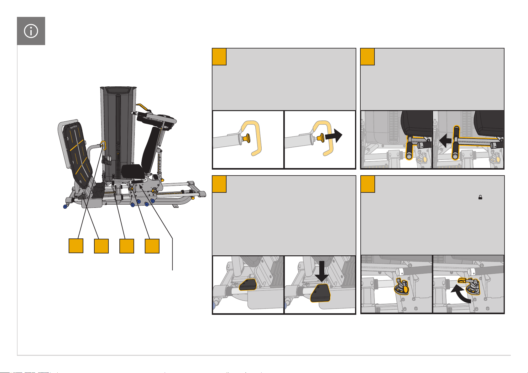
ADJUSTMENT POINTS
FOOT PLATFORM STARTING POSITION
1
Grasp handle, squeeze pin, push or pull platform
to desired start position, release pin.
Allows the user to adjust the starting position of
the footplate. The user pulls the pin and slides
the platform closer or further away to achieve
the desired knee exion at the start position.
Foot Rest
3
Grasp center of foot rest, pull out to full extension.
Gives the user a place to rest a foot
while doing 1-legged exercises.
The foot rest is not intended to support the
user’s complete body weight. Do not apply
more than 300 lbs (136 kg) to the foot rest.
Stack Release
4
To release carriage from the weight stack, grasp handle
under seat and rotate to the unlocked position .
This disengages the weight stack from the
carriage allowing the user to perform a body
weight or band resistance only leg press.
1
The seat side handles are intended to aid the user to remain
in the seat while doing the exercise. The handles are not
intended to support the user’s complete body weight. Do not
apply more than 300 lbs (136 kg) of force to the handles.
2 3 4
Foot Platform Adjustment
2
– Therapist Position
To adjust the foot platform forward or back step down on
the adjustment pad, position platform and then release.
Allows the Therapist to adjust the starting position of the
footplate. The therapist steps down on the adjustment
pad, slides the platform closer or further away from
the user to achieve the desired knee exion at the start
position, and then releases the adjustment pad.
*It is easier to do when standing at the
rear of the unit versus the side.
6
Page 7

ADJUSTMENT POINTS
Shoulder Pad Adjustment
5
Squeeze handle down and slide shoulder harness
up or down to a comfortable starting position.
Carriage Lock
7
To lock the carriage into a xed position, grasp
handle and rotate to the lockout position.
By sliding the carriage back to the range limiter
position and engaging the carriage lockout, this
allows the user to perform isometric exercises.
ENGLISH
9
Back Pad Adjustment
6
Pull pin, increase or decrease the angle of the back
pad to comfortable start position, release pin.
Allows the user to adjust the starting position of the back
pad. The user pulls the pin and slides the back pad closer
or further away to achieve a comfortable start position.
Range Limiter
8
Pull-pin and slide carriage bumper forward or
backward to limit the carriage range of motion.
5
6 7 8
0.9 kg / 2 lb Increment
9
Weight (optional)
Remove individual incremental weight pins and insert
above head plate to achieve desired starting weight.
7
Page 8

ENGLISH
MAINTENANCE CHECKLIST
PRODUCT SPECIFICATIONS
ACTION FREQUENCY
Clean Upholstery
Inspect Cables
Clean Guide Rods Monthly
Inspect Hardware Monthly
Inspect Frame Bi-Annually
Clean Machine As Needed
Clean Grips
Lubricate Guide Rods
1
Upholstery & Grips should be cleaned with a mild soap
and water or a non-ammonia based cleaner.
2
Cables should be inspected for cracks or frays and immediately replaced if present.
If excessive slack exists cable should be tightened without lifting the head plate.
3
Guide rods should be lubricated with Teon based lubricant. Apply the
lubricant to a cotton cloth and then apply up and down the guide rods.
1
2
1
3
Daily
Daily
As Needed
As Needed
WARRANTY
For North America, please visit www.matrixtness.com for warranty
information along with warranty exclusions and limitations.
Max User Weight 159 kg / 350 lbs.
Max Training Weight 139.6 kg / 308 lbs.
Product Weight 314 kg / 693 lbs.
Weight Stack 136 kg / 300 lbs.
Add-On-Weight (optional) 0.9 kg / 2 lbs. effective resistance
Overall Dimensions
(L x W x H)*
205 x 122 x 189 cm /
81” x 48” x 74.25
* Ensure a minimum clearance width of 0.6 meters (24”) for access to and pas-
sage around MATRIX strength equipment. Please note, 0.91 meters (36”) is the
ADA recommended clearance width for individuals in wheelchairs.
TORQUE VALUES
M10 Bolt (Nyloc Nut & Flowdrill) 77 Nm / 57 ft -lbs
M8 Bolts 25 Nm / 18 ft-lbs
M8 Plastic 15 Nm / 11 ft-lbs
M6 Bolts 15 Nm / 11 ft-lbs
Pad Bolts 10 Nm / 7 ft-lbs
8
Page 9
UNPACKING
Thank you for purchasing a MATRIX Fitness product. It is inspected
before it is packaged. It is shipped in multiple pieces to facilitate the
compact packaging of the machine. Prior to assembly, conrm all the
components by matching them with the exploded diagrams. Carefully
unpack the unit from this box and dispose of the packing materials in
accordance with your local laws. Exercise device must be assembled
by a trained assembly team or be pre-assembled prior to delivery.
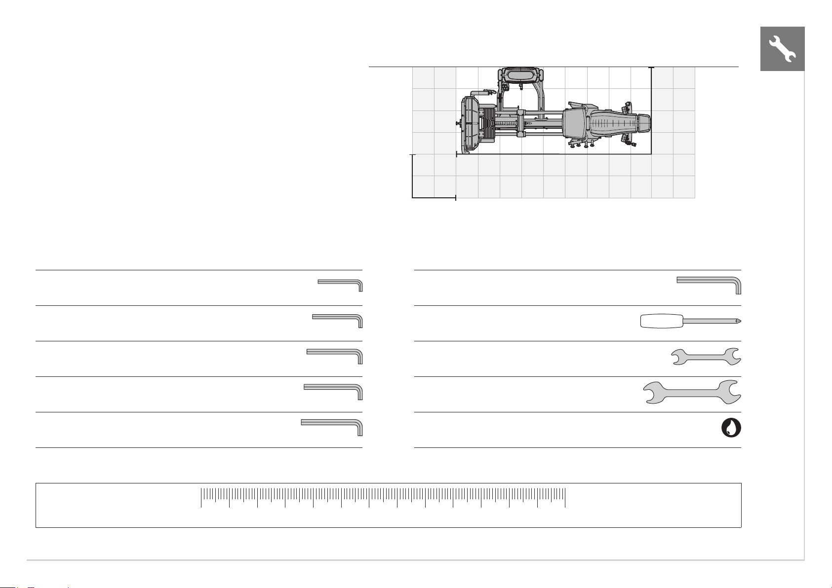
MD-S70 TRAINING AREA
CAUTION
To avoid injury to yourself and prevent damage to the frame
components, be sure to have proper assistance removing the frame
pieces from this box. Please be sure to install the equipment on a
stable base, and properly level the machine. Ensure a minimum
clearance width of 0.6 meters (24”) for access to and passage around
MATRIX strength equipment. Please note, 0.91 meters (36”) is the
ADA recommended clearance width for individuals in wheelchairs.
FREE AREA
0.6 M (2 FT)
WIDE PATH
TOOLS REQUIRED FOR ASSEMBLY (not included)
3MM L-Shaped Allen Wrench 10MM L-Shaped Allen Wrench
4MM L-Shaped Allen Wrench Phillips Screwdriver
2.70 M
(106”)
1.22 M
(48”)
ENGLISH
5MM L-Shaped Allen Wrench 8MM Open-End Wrench
6MM L-Shaped Allen Wrench 17MM Open-End Wrench
8MM L-Shaped Allen Wrench Guide Rod Lubrication
If any items are missing please contact your country’s local MATRIX dealer for assistance.
0 mm 10 20 30 40 50 60 70 80 90 100 110 12 0 130
9
Page 10

1
2
5
4
3
6
ENGLISH
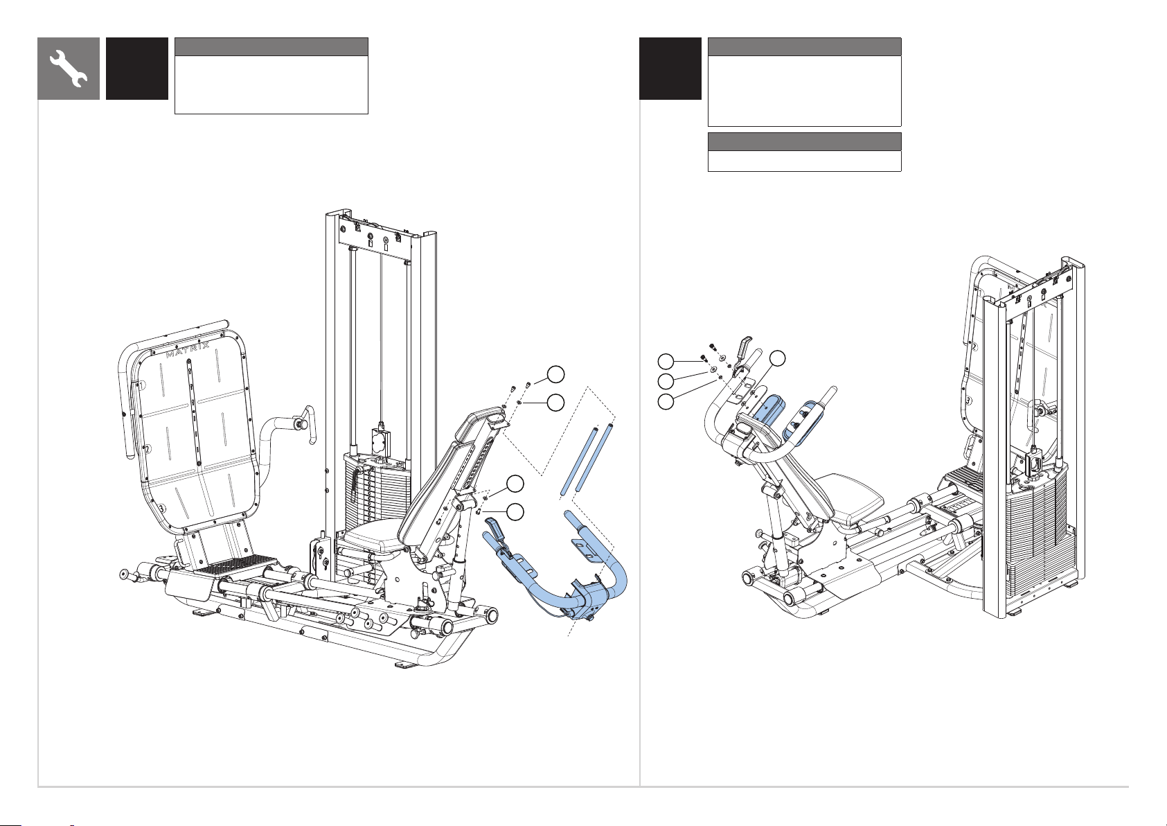
1 2
Keep pull pin in the lock position
Step 2 Hardware
Description Qty
A
Bolt (M10x150L)
B
Arc Washer (Φ10.2)
C
Nut (M10)
D
Hex Head Bolt (M10x20L)
E
Spring Washer (Φ10.2)
F
Washer (Φ10.2)
D
E
F
Do not fully tighten frame connectors until
assembly is complete. Vibra-Tite 135 Red Gel
or equivalent must be used on all fasteners
4
that are not assembled with Nylock Nuts.
8
4
2
2
2
C
B
B
A
10
Page 11

Step 3 Hardware
3 4
Description Qty
D
Hex Head Bolt (M10x20L)
E
Spring Washer (Φ10.2)
F
Washer (Φ10.2)
2
2
2
Step 4 Hardware
Description Qty
B
Arc Washer (Φ10.2)
D
Hex Head Bolt (M10x20L)
E
Spring Washer (Φ10.2)
F
Washer (Φ10.2)
G
Socket Head Bolt (M10x20L)
H
Pre-installed Nut (M12)
H
2
2
4
2
2
1
ENGLISH
B
E
D
D
E
F
F
E
Cable
G
11
Page 12

ENGLISH
5 6
Step 6 Hardware
Description Qty
C
Nut (M10)
F
Washer (Φ10.2)
I
Bolt (M10x75L)
J
Bolt (M10x30L)
K
Pre-installed Screw (M5x20L)
6
14
6
2
4
K
12
F
J
I F F
C
Page 13

2
1
3
Step 7 Hardware
7 8
Description Qty
FGWasher (Φ10.2)
Socket Head Bolt (M10x20L)33
ENGLISH
Route cable through hole and attach using
pre-installed hardware
F
G
13
Page 14

ENGLISH
9
Step 9 Hardware
Description Qty
K
Pre-installed Screw (M5x20L)
L
Screw (M8x20L)
M
Washer (Φ8.2)
Step 10 Hardware
4
4
4
K
10
Description Qty
F
Washer (Φ10.2)
G
Socket Head Bolt (M10x20L)
N
Socket Head Bolt (M10x25L)
F
G
4
4
2
N
14
M L
Page 15

3
1
2
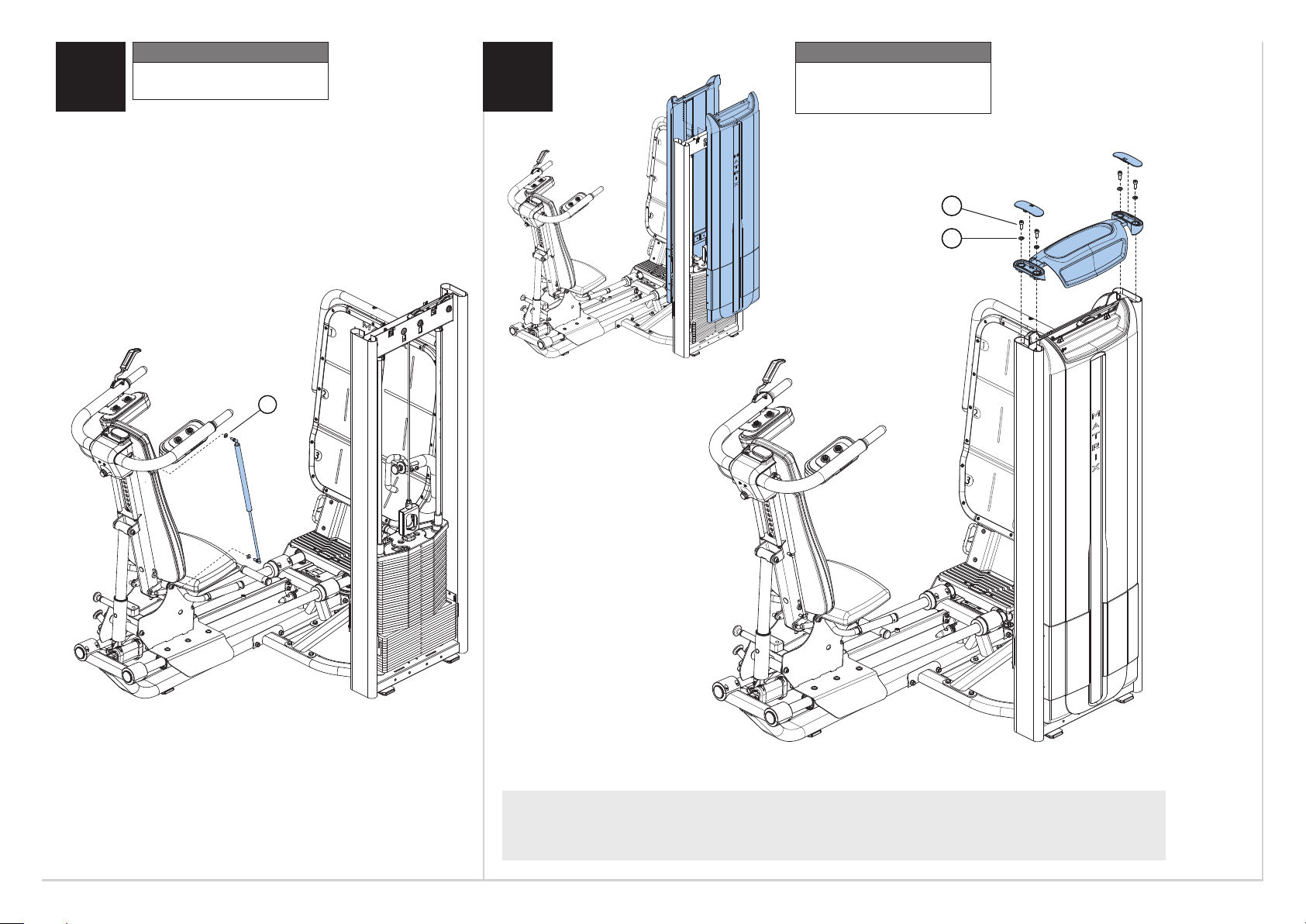
11 12
Step 12 Hardware
Description Qty
N
Socket Head Bolt (M10x25L)
O
Plastic Cap
P
Bolt (M8x15L)
Q
Rubber Stopper
2
2
2
2
ENGLISH
O
N
P
Q
N
O
15
Page 16
ENGLISH
13
Step 13 Hardware
Description Qty
D
Hex Head Bolt (M10x20L)
F
Washer (Φ10.2)
G
Socket Head Bolt (M10x20L)
Step 14 Hardware
2
4
2
14
Description Qty
R
Special Screw
S
Nylon Washer (Φ13.2)
T
Plastic Spacer
U
Ring
Torque Value
2.5 Nm / 22 in -lbs
4
4
4
4
G
F
F
D
R
T
U
S
16
Page 17
Step 15 Hardware
15 16
Description Qty
F Washer (Φ10.2) 2
F
Step 16 Hardware
Description Qty
MVWasher (Φ8.2)
Bolt (M8x25L)
4
4
V
M
ASSEMBLY COMPLETE!
17
Page 18

D
CBA
OPTIONAL ASSEMBLY (SOLD SEPARATELY)
ENGLISH
INCREMENTAL WEIGHTS
Hardware
Description Qty
A
Plug (pre-installed)
B
Bolt (M10x20L)
C
Spring Washer (Φ10.2)
D
Arc Washer (Φ10.2)
FORCE PLATE HOLDER
2
2
2
2
Set of 4 with
holder. Each
weight adds
0.9 kg / 2 lbs
of effective
resistance to
the exercise.
STEP STOOL
Small platform
used to help
users enter the
machine.
ACCESSORY PACK
Tyrmotion (TYMO) force
plate sold seperately
Contains the following items attached
magnetically to the front of the Leg Press
foot plate:
Used to attach a Tyrmotion
(TYMO) force plate (sold
separately) to the front of the
Leg Press foot plate.
• Heel Cup
• Wedge Block
• Wire Mount (holds inatable disk or
balance pad sold separately)
18
Page 19

19
Page 20

MD-S70
© 2019 Johnson Health Tech
Part # XXXXXXXXXX
Rev 1.2 A
 Loading...