

Page 1

Table of Contents
1.0 SPECIFICATIONS .....................................................................3
1.1 High Altitude Operation .......................................................... 3
2.0 INSTALL ATION REQUIREMENTS .............................................4
2.1 Location ................................................................................ 5
3.0 VENTING .................................................................................. 6
Attachi ng Ve nt Pipi ng to Boiler ..................................................... 6
3.1 Vent Pipe Material..................................................................7
3.2 Venting Config uratio ns...........................................................7
3.3 Venting Rules and Guidelines.................................................9
3.4 Venting Clearances..............................................................10
3.5 Determining Vent Lengths ....................................................10
3.6 Outdoor Venting...................................................................11
4.0 CONDENSATE DRAIN ............................................................ 12
5.0 INSTALLING GAS PIPING .......................................................13
5.1 Installation...........................................................................13
5.2 Testing and settings.............................................................13
6.0 BOILER PLUMBING................................................................15
6.1 Plumbing (Minimum Requirements).......................................16
6.2 Matrix Boiler Connectio ns.....................................................17
6.3 Hydronic Heating Additions (Optional)...................................17
7.0 DOMESTIC HOT WATER SYSTEM ..........................................23
7.1 Operation and Set-up...........................................................23
7.1.2 Matrix DHW with Storage...................................................25
8.0 WIRING...................................................................................26
8.1 Field Wiring to Matrix............................................................26
8.2 Matrix Factory Wiring Sche matic...........................................27
9.0 CONTROL SETUP...................................................................29
9.1 Controller Displays...............................................................29
9.2 Operation and Set-up...........................................................30
9.3 Outdoor Sensor Oper at ion....................................................32
10.0 MATRIX BLOWER OPERATION............................................33
10.1 Forced Air Heating .............................................................33
10.2 Duct Sizing........................................................................ 34
11.0 HEAT RECOVERY VENTILATION.........................................35
11.1 Ventilatio n Needs...............................................................35
11.2 Types of Installation........................................................... 36
11.3 Damper Box ......................................................................37
11.4 Condensate Drain..............................................................37
11.5 HRV Balancing ..................................................................38
12.0 LIGHTING BOILER................................................................40
12.1 Initial Start-Up ....................................................................40
12.2 Re-Lig hting Unit .................................................................40
12.3 Turn Off Appliance .............................................................40
13.0 T ROUBLE SHOOTING .......................................................... 41
Matrix
Matrix Boiler Only
VERSION DATE: 2-7-08
14.0 SEQUENCE OF OPERATION................................................45
15.0 INSTALLATION CHECKLIST.................................................46
16. 0 ANNUAL MAINTE NANCE AND INSP ECTION ........................47
16.1 Combustion Chamber Cleaning ..........................................47
16.2 HRV/Air Hand ler Maintena nce ............................................47
17.0 PARTS LIST..........................................................................48
18.0 WARRANTY.......................................................................... 49
US Models
Page 2
Matrix Installation a nd Operatio n Instructions
WARNING
THIS APPLIAN CE I NCORPOR ATES A CERTIFIED LO W PRESSURE BOIL ER, WHICH M UST OPPERATE W ITH
A SUST AINED W ATE R PRESS URE. F AILURE TO MAINTAIN W ATE R PRESS URE W ILL D AM AGE T HE UN IT
AND VOID THE WARRANTY.
CAUTION
IT IS T HE RESPON SIBIL IT Y OF T HE HOM EOW NER TO KEEP T HE VENT TERM INAL CLE AR OF SNO W AN D
ICE.
CAUTION
CERTIFIED C ARBO N M ONIXIDE D ETECTORS MUST BE INSTALLED ( SEE SECTION 2.0)
2
Page 3

Matrix Installation a nd Operatio n Instructions
1.0 SPECIFICATIONS
Table 1. 1 Gener al Spec i fic at ions
Model
M100 25-150
M100V 25-150
Input
MBH
Output
MBH
23-
139
23-
139
Steady State
Efficiency %
95 92.7 20x16 18x18 300-1200 400-1600 - 53-28-38 3”
95 92.7 20x16 18x18 300-1200 400-1600 70-150 53-28-38 3”
AFUE
%
Supply
Plenum
inches
Return
Plenum
inches
Airflow
Heating
CFM
Airflow
Cooling
CFM
Ventilatio n
CFM
Dimensions
H-W-D
Vent/Air
Size
1.1 High Altitude O per at ion
The Matrix is designed to operate to capacity
Figur e 1.1 Maximum Capacity vs. Altitud e
160
in installations at 2000 feet of elevation or
less. As elevations higher than 2000 feet
have less dense air, the uni t is not capable of
150
providing its specified capacity. (See Chart).
140
In Cana da:
De-rate by 5% for altitudes between 2000
and 4500 feet. For altitudes above 4500 feet
Input ( M bh)
130
consult with local authorities.
In US A:
120
De-rate by 4% for every 1000 feet over 2000
feet.
110
0-2000 3000 4000 5000 6000 7000 8000 9000 10000
Elevation (ft)
CAUTION
AT ELEVATIONS GREATER THAN 2000 FEET, THE COMBUSTION OF THE MATRIX MUST BE CHECKED
WIT H A CALI BRATED CO MBU STION T EST ER TO ENS URE SAFE AND R ELIAB LE OPE RATION. CONS ULT
SECTIO N 5.20 FO R INST RUCTIONS ON ADJU STING T HE INPUT TO PRO VIDE PROPER OPERATION.
IT IS THE INSTALLERS RESPONSIBILITY TO CHECK THE COMBUSTION, AND
TO ADJUST THE COMBUSTION IN ACCORDANCE TO SECTION 5.20
3
Page 4
Matrix Installation a nd Operatio n Instructions
2.0 INSTALLATION REQUIREMENTS
The installation of your NY Thermal Matrix gas furnace/boiler must conform to the requirements of your local authority, and the
National Fuel Gas Code ANSI Z223.1 and or CAN/CGA B149 Installation Codes. Where required by the Authority, the installation
must confor m to the standard for “Controls and Safety Devices for Automatically Fired Boilers ANSI/ASME CSD-1.
IMPORTANT
Carbon Monoxide Detectors
Many jurisdictions require the installation of carbon monoxide detectors in buildings where a sidewall
vented fuel-bur ning appliance is inst alled. In stallers m ust abide by local co de requ ire ments regard ing the
installation of CO detectors. The use of a certified carbon monoxide detector is recommended but not
required by NT I.
IMPORTANT
“IN THE STATE of M ASSACHUSETTS ONLY”
(a)For all horizontally vented gas fueled equipme nt installed in every dwelling, building or structure used in whole or in part
for residential purposes, including those owned and operated by the Commonwealth and where the side wall exhaust vent
termination is less than seven (7) feet above finished grade in the area of the venting, including but not limited to decks and
porches, the following requirements shall be satisfied:
1. INSTALLATION OF CARBON MONOXIDE DETECTORS. At the time of installation of the side wall horizontal
vented gas fueled equipment, the installing pl umber or gas fitter shall observe that a hard wired carbon monoxide
detector with an alarm and battery back-up is installed on the floor level where the gas equipme nt is to be installed and
on each additional level of the dwelling, building or structure served by the equipment. It shall be the responsibility of
the property owner to secure the services of qualified licensed professionals for the i nstallation of hard wired carbon
monoxide detectors.
a. In the event that the side wall horizontally vented gas fueled equipment is installed in a crawl space or an
attic, the hard wired carbon monoxide detector with alarm and battery back-up may be installed on the next
adjacent floor level.
b. In the event that the requireme nts of this subdivision can not be met at the time of completion of installation,
the owner shall have a period of 30 days to comply with the above requirements; provided, however, that
during said 30 day period a battery operated carbon monoxide detector with an alarm shall be installed.
2. APPROVED CARBON MONOXIDE DETECTORS. Each carbon monoxide detector as required in accordance with
the above provisions shall comply with NFPA 720 and be ANSI/UL 2034 listed and IAS certified.
3. SIGNAGE. A metal or plastic identification plate shall be permanently mounted to the exterior of the building at a
minimum height of ei ght (8) feet above grade directly in line with the exhaust vent terminal for the horizontally vented
gas fueled heating appliance or equipment. The sign shall read, in print size no less than one-half (1/2) inch in size,
“GAS VENT DIRECTLY BELOW. KEEP CLEAR OF ALL OBSTRUCTIONS”. (A plate is included with the
boiler)
4. INSPECTION. The state or local gas inspector of the side wall horizontally vented gas fueled equipment shall not
approve the installation unless, upon inspection, the inspector observes carbon monoxide detectors and signage
installed in accordance with the provisions of 248 CMR 5.08(2)(a)1 through 4.
(b)EXEMPTIONS: The following equipment is exempt from 248 CMR 5.08(2)(a)1 through 4:
1. The equipment listed in Chapter 10 entitled “Equipment Not Required To Be Vented” in the most current edition of
NFPA 54 as adopted by the Board; and
2. Product Approved side wall horizontally vented gas fueled equipment installed in a room or structure separate from the
dwelling, building or structure used in whole or in part for residential purposes.
…..Next Page
4
Page 5

Matrix Installation a nd Operatio n Instructions
….Continued.
(c)MANUFACTURER REQUIREMENTS – GAS EQUIPMENT VENTING SYSTEM PROVIDED. When the manufacturer
of Product Approved side wall horizontally vented gas equipment provides a venting system design or venting system
components with the equipment, the instructions provided by the manufacturer for installation of the equipment and the venting
system shall include:
1. Detailed instructions for the installation of the venting system design or the venting system components; and
2. A complete parts list for the venting system design or venting system.
(d)MANUFACTURER REQUIREMENTS – GAS EQUIPMENT VENTING SYS TEM NOT PROVIDED. When the
manufacturer of a Product Approved side wall horizontally vented gas fueled equipment does not provide the parts for venting
the flue gases, but identifies “special venting s ystems”, the following requirements shall be satisfied by the manufacturer:
1. The referenced “special venting system” instructions shall be included with the appliance or equipment installation
instructions; and
2. The “special venting systems” shall be Product Approved by the Board, and the instructions for that system shall
include a parts list and detailed installation instructions.
(e)A copy of all installation instructions for all Product Approved side wall horizontally vented gas fueled equipment, all
venting instructions, all parts lists for venting instructions, and/or all venting design instructions shall remain with the appliance
or equipment at the completion of the installation.
ATTENTION
The Matrix is se t t o operate with Natural Gas; LP Co nversion Kit Part No. 82650- 1 is i ncluded with e ac h furnace and
must be installed before operating with Propane.
Liquefied Petroleum (LP) propane gas is heavie r than air; it is imperative that your boiler is not installed i n a pit or
si mila r lo ca t io n that wi ll pe r mit he a v ie r t ha n a i r ga s t o co llect . Lo ca l Code s may re qu i re a pp lia nces f ue led wit h LP g a s
be provided with an approved means, of removing unburned gases from the room.
Check your local codes for this requirement.
2.1 Location
In all cases, the Matrix must be installed indoors, in a dry location, such that the gas components are protected from dripping or
spraying water or rain, during operation and servicing. T he boiler location ambient temperature is mai ntai ned to a mi ni mum of
50°F.
Determi ne the best location of the vent termination, and if possible locate the appliance as close to the termination point as possible.
Ensure that the desired appliance location is not subjected to flooding or high moisture levels, for damage to the appliance will
occur, voiding your NY THERMAL warranty.
LIQUIFIED PE TROL EUM (LP) PROPANE
IMPORTANT
CLEARANCES
For proper and saf e installation adhere to the f ollowing c learances t o com bust ib les:
Furnace Casing = 0" Floor = Combustible Flue Pipe: Boxed in or enclosed = 2”
The f ollowing are the minimum clearances r ecommended f or ser vicing:
Front = 24” Back = 6"( opt ional return plenum locati on) Top = 12"
Sides = 24" Bottom = 0”
In free air = 0”
5
Page 6
Matrix Installation a nd Operatio n Instructions
p
3.0 VE NTING
The NY Thermal Matrix is a high efficiency condensing gas furnace/boiler utilizing induced power venting. Exhaust gases are to
be vented directly outdoors, using the venting me thod detailed in this section. Under no conditions, may this unit vent gases into a
masonry chimney, unless it is vacant, and utilizes Matrix approved venting material as illustrated in the figures in this section.
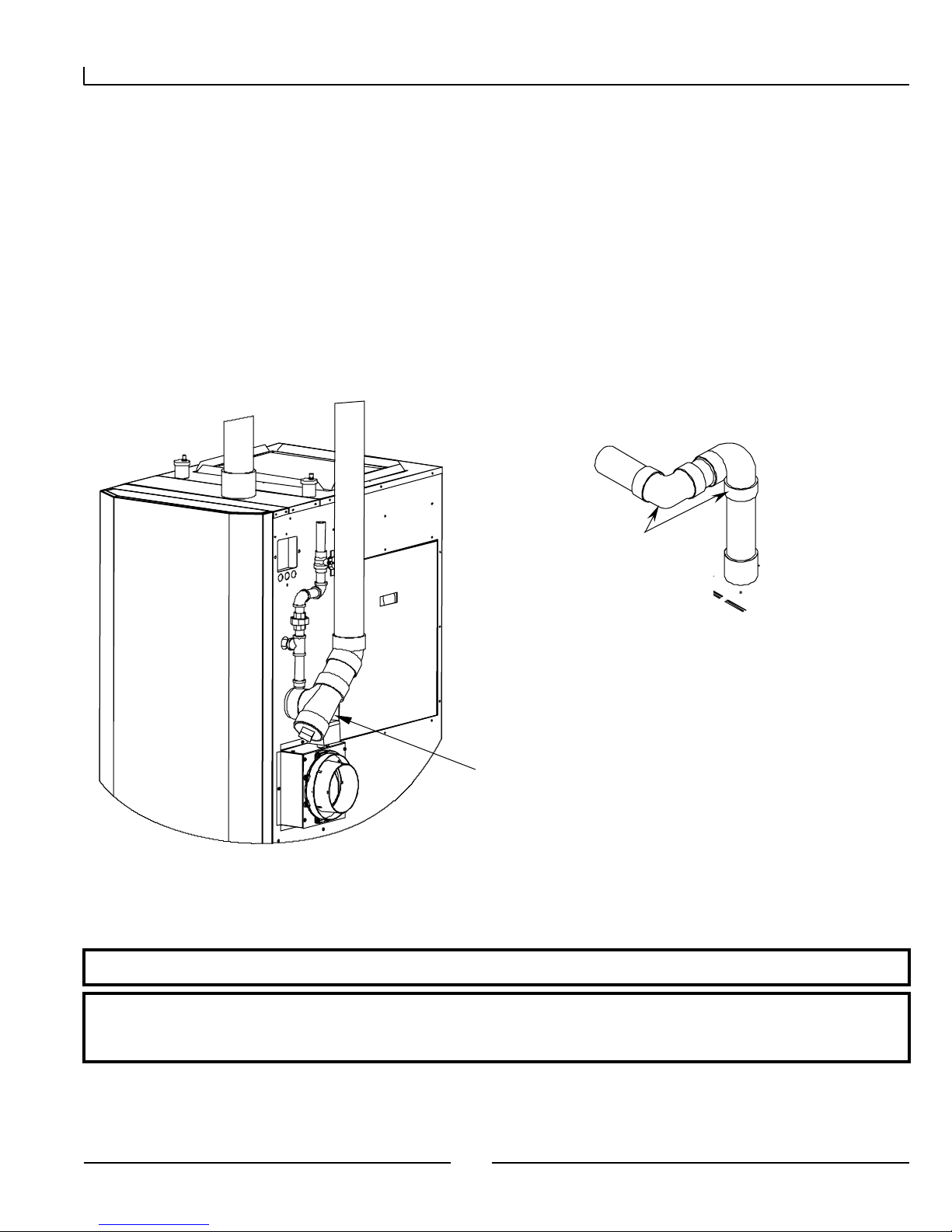
Attaching Vent P ipi ng t o Boi ler
It is extremely important for the inta ke and exhaust piping to be adapted to the appropriate size immediately upon exiting the boiler
cabinet. The Matrix comes with a 3” male PVC fitting to connect the air intake port of the boiler.
The Matrix exhaust connection is 3” male PVC, use approved cement to connect to venting system.
Check t he fl ue outlet gasket for prop er i nser ti on and sea ling prior to and after attachi ng the ve nting.
Ensure the venting system does not apply a load or stain on the flue outlet of the boiler (recommend using two elbows to create a
“swing joint” as shown above).
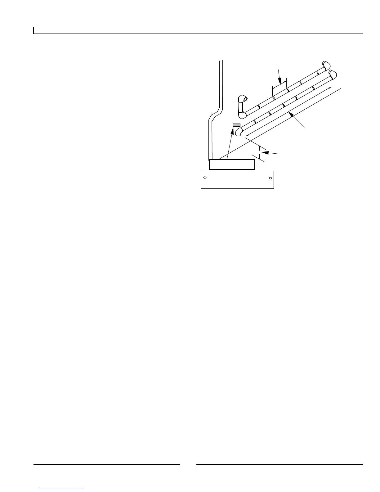
Fig ur e 3.1 Venting Const r uction
It is recommended that two elbows be
used, so that the slope of the hori zontal
exhaust vent does not affect the vertical
lumb of the pipe connected to the boiler.
Slope all horizontal indoor exhaust
vent ing ¼” to ½” per linear foot.
It is recommended to have a collection point
for condensation in the intake venting.
Condensation can then be drained to an
open house dr ain or condens ate pump.
Drain line from intake must have an
appropriate trap or shut off valve to avoid
siphoning.
IMPORTANT
The vent connection and piping must be perfectly aligned to the furnace connection. AND MUST NOT
APPLY ANY W EIGHT OR LATERAL FORC E TO T HE FLU E BOX. NTI do es not warrant y damages to t he flu e
box.
6
Page 7

Matrix Installation a nd Operatio n Instructions
p
3.1 Vent Pipe Mat erial
IMPORTANT
Field supplied piping and fittings are required to complete the installation. Selection of the vent pipe
material must be based upo n the Local codes and regulations. The Matrix is certified to oper ate under all
conditions using the following vent ing material:
Exhaust Vent Pip ing:
The first 3 feet of the exhaust venting must be readily accessible for inspect ion.
In Canada all exhaust pipe, fittings and cement must comply with ULC S636 (As per ULC S636, only CPVC can be
used).
In U.S. exhaust pipe and fittings must comply with ANSI/ASTM D1784 and DF441 for PVC and CPVC respectively.
Cement and primer must comply with ANSI/ AST M D2564 and F493 for PVC a nd CPVC respectively.
1. 3 ” PVC Sch.40 ( US only, not per mitted in Ca nada) .
2. 3 ” CPVC Sch.40.
Air Supply Pipe:
1. 3 ” ABS.
2. 3 ” PVC Sch.40.
3.2 Venting Confi gur at ions
See Chart f or m aximum l engt hs
See Chart for max i m um l engths
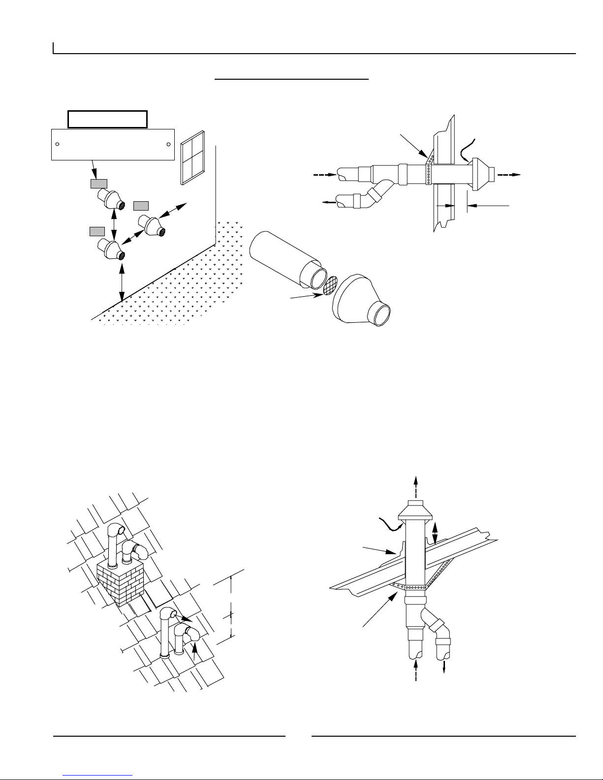
3.2.1 Two-Pipe Vent Termination
Fig ur e 3.2 Two-Pi pe Vent Ter m i nati on
Coupling and
elbow to be
against wal l
– ½ ” play is
acceptable
Exhaust
Intake
The ver tical portion of the exhaust
termination does not require
insulation, if less than 5 feet in
total length
”
12” Plus Snow allow ance
Example 12+19=31”
Must insert
lastic bird
screen
Apply Plate Here
Gas Vent Direct ly Below
Keep Free of Obstruc t ions
Exhaust
Intake
Out sid e W all”
Window
Exhaust
36”
18”
4”-12” or great er
than 36”
Intake
12” Plus Snow
Allo wance Min”
7
Page 8
Matrix Installation a nd Operatio n Instructions
p
p
w
Apply
(
g
3.2.2 Concent r ic Vent Termination (No longer appr oved for Canada)
Fig ur e 3.3 Conc e nt ric Vent Ter mina t i on
Plate Here
Gas Vent Directly Belo
Keep Free of Obstruc t ions
48” min.
4” or greater
than 24”
Minim um 12”
lus snow
allowance
36” min.
Exhaust
Inlet air
Note: inlet pipe must always
be connected to the boiler.
Must insert
lastic bird
screen
Support
(Fie ld installed)
Inlet air
Use NTI part # 82666 or York part # 1CT0303
Instructions included with vent terminal contain more detailed assembly and installation instructions.
Clearances and requirements of this manual supersede those of the instructions incl uded with the vent terminal.
Terminal must be cemented together during installation.
Exhaust
Must be 1”
from wall
3.2.3 Roof Vent ing
Figure 3.4 Roof Vent i n
Roof weat her seal
Flashing (field supplied)
18”
12” Plus
Snow
Support
Field supplied)
Note: inlet pipe must
always be connected
8
Page 9

Matrix Installation a nd Operatio n Instructions
IMPORTANT
USE OF EXI STING CHIMNEY
It is permissible to run vent pipe t hrough an exist i ng chimney as long as:
1. The chim ney is not to be used by any other appliance.
2. Flue gases don’t enter the vacant chim ney.
3. O nly Trinit y c er t ified venti ng materials are used, see Sect ion 3.1.
4. Vent lengths are within the maximums specified.
3.3 Venting Rules and G uide lines
1. It is highly recommended that the vent termi nal be located where it will not be exposed to normal prevailing winds.
2. The exhaust mus t be a minimum of 18” above the air inlet, and the air inlet must always be a minimum of 12” plus snow
allowance above any surface that will support snow. (Two feet plus snow allowance is highl y recommended). Consult your weather
office, for the maximum typical snowfall for your region. Example: New Brunswick Canada the typical maximum snowfall is 19”,
Thus in figures of Section 3.3, the inlet must be (12”+19”) = 31” off the ground, the exhaust mus t be (31”+18”) = 49”.
The horizontal distance between the inlet and exhaust must be a minimum of 4” center to center. If the horizontal distance between
the inlet and exha ust is more then 12”, increase the vertical separation by the same amount. Example: If horizontal separation is
24”, a minimum vertical separation of 30” is required (24”-12”=12”), so increase mini mum vertical separation by 12”),
(18”+12”=30”). If horizontal distance is greater then 6’, no additional vertical spacing is required. Vertical separation is never
required to be greater then 36”.
3. Under normal operating conditions this appliance will produce a plume of white gases, and sho uld be taken into consideration
when selecting an adequate location. A 3’ diameter stainless, plastic, or vinyl shield can be used to flash the exterior of the
residence.
4. If the horizontal distance between the inlet and exhaust is more then 12”, increase minimum vertical separation by the same
amount. (If horizontal distance is greater then 6’, no additional vertical spacing is required). Example, horizontal separation
equal to 24” require s a mi nimum ve rtical separation of 18”+(24”-12”) =30”. (Vertical separat ion is neve r re quired t o be
greater then 36”)
5. Elbows on outside of wall must be no greater than ½” away from the wall.
All indoor exhaust piping mus t be on a slope back to the boiler a minimum of ¼” per linear foot of vent. For applications where
excessive condensation is possible ½” per linear foot is recommended. (See figure after #11. Recommended way to have plumb
pipe connection to boiler.)
6. Exhaust vent pipe can be secured to the wall for more rigidity.
7. In all roof applications the discharge must point away from the pitch of the
roof.
8. Install adequate flashing where the pipe enters the roof, to prevent water
leakage.
9. Install and seal a rain cap over existing chimney openings, in vacant
chimney applications.
10. For installations that exit the wall below grade. Excavate site as shown in
figure, to a point below where the pipes are to exit. Ensure tha t the wall is
fully sealed where the pipes penetrate the wall. The vent piping MUST be
secured to the side of the building above grade, as shown, to provide rigidity.
NTI provides a mounting bracket, PN:82075, for securing the exhaust pipes.
Ensure that the vent clearances are maintained (Inlet mi nimum 12” plus snow
allowance from grade, exhaust outlet 18” mi nimum above inlet)
11. Install the vent screens provided into both the inlet and exhaust vent
terminal elbows. The screen must be on the outside of the last elbow. Install
the screen into the female opening of the elbow. Then cut a s mall piece of
pipe to sandwich the screen into the elbow. NOTE be sure that the small piece of pipe cut, does not extend past the end of the
elbow. Two screens are provided in the package.
12. It is extremely important that the intake and exhaust piping be adapted to the appropriate size immediately upon exiting the
boiler cabinet.
13. All interior vent pipe shall be supported a minimum of every 36”.
Figure 3.5 Installing Venting Below Grade
9
Page 10

Matrix Installation a nd Operatio n Instructions
3.4 Venting Clearances
These are code restrictions for the location of the Flue gas vent ter minal. Compliance doesn’t insure a satisfactor y installation; good
common sense must also be applied.
The vent terminal shall not t er minate:
1. Directly above a paved sidewalk or a paved driveway that is located between two buildings, and that serves both buildings;
2. Less than 7 feet above grade where located adjacent to a paved walkway or driveway located on public property.
3. Within 3' (three feet) of a window or door that can be opened, or non-mechanical air supply inlet to any building.
4. Within 6’ of a mechanical air supply inlet to any building, or roof eve containing soffit openings.
5. Above a meter/regulator assembly withi n 3' horizontally of the vertical centerline of the regulator.
6. Within 3' horizontally of any gas service regulator vent outlet up to a height of 15’.
7. Less than 30” plus snow allowance above grade, or any surface that will support snow, ice, or debris. The exhaust must be a
minimum of 18” above the air inlet, and the air inlet must always be a mi nimum of 12” plus snow allowance above any surface that
will support snow. (Two feet plus snow allowance is highly recommended). Consult your weather office, for the maximum typical
snowfall for yo ur regi o n.
8. Underneath a wooden verandah, porch, or deck.
9. Underneath cement verandah, porch, or deck, unless both ends are open and the exhaust pipe is installed at least 24” under the
deck floor.
10. So situated that the flue gases are directed towards brickwork, siding, or other construction, in such a manner that may caus e
damage fro m heat or co ndensate from the fl ue gas es.
11. Less than 3’ from an inside corner of an L-shaped structure (including walls and fences).
12. Install the warning plate “Gas Vent Di re c t ly B e lo w” 4 feet above the location of the air inlet pipe, so it is visible from at least
eight (8) feet away (Plastic Label included in the Installation Manual Package – see figure).
3.5 Deter mining Vent Lengt hs
Use the following chart to determi ne the maximum amount of vent pipe that can be used. This chart calculates, sweep and 45º
elbows, and 90º elbows at 5 equivalent feet. Note: chart shows allowable equivalent vent lengths for intake and exhaust vents
separately, thus an M100V operating on Natural Gas can be installed with 105 equivalent feet of intake venting and 105 equivalent
feet o f exhaus t venti ng.
IMPORTANT
The length of one vent p ipe (intake or exha ust) ma y not exceed t he lengt h of the other vent pipe by mor e
then 20 equivalent f eet .
The thr ee 90° elbows of t he exterior vent piping (two outlet, and one inlet) do not have to be included, as
they are taken into considerat ion in t he vent calculations.
Propane Gas (LP) maximu m vent length cannot exceed 50 equivalent f eet .
Table 2 Maximum Vent Lengt h
Number of Elbows or 45's
Model
M100
M100V
Vent
Type
3"Natural 105 1009590858075706560
3" LP 50 45 40 35 30 25 20 15 10 5
Gas
Max. Equiv.
Length
123456789
10
Page 11
Matrix Installation a nd Operatio n Instructions
3.6 Out door Vent ing
Vent piping outside the Building is permitted under the
following conditions:
The maximum length outside the building is 20 feet. (Outdoor
length must be included in the overall vent length calculation.)
All normal termina tion clearances are maintained.
All exterior exhaust vent pipes are insulated with 3.5”-ID, ½”-
thick, Closed Cell Foamed Polyolefin Tubing i.e., “Tundra Seal
Plus” or equivalent.
The pipe is supported every 24”
The exhaust and inlet are sloped back to the boiler ½ ” elevation
for every foot.
Fig ur e 3.6 O utd oor Venting
Support s every 24”
Exhaust
Inlet
Apply Plate Here
Gas Vent Direct ly Below
Keep Free of Obstruc t ions
Maximum of 20 feet
is permitted for
outside a building
usin g 3” pipe ONLY.
12” plus all owance above
grade for snow
11
Page 12
Matrix Installation a nd Operatio n Instructions
4.0 CON DE NS ATE DRAIN
This unit produces water as a product of combustion. Much of this water condenses on the heat exchanger and in the venting
system. All exhaust piping must be on a slope back to the boiler ¼” per linear foot of vent. Steps must be taken to ensure that
condensate does not collect in the venting system. Condensate must be drained from the boiler into a household drain.
WARNING
FAILURE TO PROPERLY CONNECT THE CONDENSATE LINE WILL CAUSE COMBUSTION GASES TO
ENTE R THE ROOM, POSSIBLY C AUSING SERIOUS INJ URY T O OCCUPANTS O R DEATH.
Note: c hec k with your munici pality, or l ocal ga s co mpa ny to determine i f
disposal of combustion condensate is permitted. In the State of Massachusetts
the condensate must be neutralized prior to entering a drain.
The following are important notes that must be taken into consideration when
constructing the condensate system:
DO NO T run condensate line outside. A frozen or blocked drain will cause the
condensate to fill the combustion chamber. This will result in a no heat
condition, as the unit will shut down, and damage to the flame sensor, and
components can occur.
NEVER use copper, steel, or galvanized piping in the construction of the
condensate system (condensate is very corrosive and will wrought most me tals).
When a condensate pump is used or required, select a pump that is designed for
residential furnaces.
Fig ur e 4.1 Cond ens at e Drain Plumbi ng
Condensate
Drain From
Boiler
Nipple mu st
be cut.
Drain must be
open t o allow
overfl ow if
blocked
Drain must
include trap
12
Page 13
Matrix Installation a nd Operatio n Instructions
5.0 INSTALLING GAS PIPING
5.1 Installation
Fig ur e 5.1 G as Inlet Connection
Refer to the current National Fuel Gas Code ANSI
Z223.1/NFPA 54 or CAN/CGA B149.1 installation
codes, and local codes for gas piping requirements and
sizing.
It is hig hly recomme nded to use
flexibl e gas pipe, the gas valve and
blower cannot support the weight of
piping. I f piping is used, ensure that
the valve supports NO WEIGHT
Gas cock shut
Off Valve to be
"T" type h an d le
Pipe size runnin g t o t he unit depends on:
• Length of pipe.
• Number of fittings.
• Type of gas.
Gas valve
• Maximum inp ut requirement of all gas
appliances in the residence.
Ensure that:
• Flexible gas pipe is used (if acceptable by
local codes). The gas valve and blower cannot
support the weight of piping, leading to blower
vibration and damaged components. If rigid piping is used, ensure that the valve supports NO WEIGHT
• You plan the installation so that the piping does not interfere with the vent pipe, or the removal of the valve, burner, and
serviceable components.
• The Boiler shall be installed such that the gas ignition system components are protected from water (dripping, spraying,
rain etc.) during installation and servicing.
• The gas piping is large enough for all the appliances in the home. No appreciable drop in line or manifold pressure should
occur when any unit (or combination of units) lights or runs.
• Al ways use a pipe- thr eading compo und t ha t i s resistant to pr opa ne (LP) gas s olvent actio n. Us e spar ingl y to all male
threads, starting at two threads from the end. Over doping or applying dope to the female end, can result in a blocked gas
line.
DO NOT TIGHTEN FITTINGS WITHOUT SUPPORTING THE GAS VALVE as damage to the valve or motor can occur.
Install a manual “equipme nt Shut-Off Valve” as shown. Valve must be listed by a nationally recognized testing lab.
5.2 T esting and sett ings
Gas line and regulator(s) must be able to support a line pressure at the gas valve of 4-9”w.c for Natural Gas and 9-12”w.c for LP
while running at maximum rate. Matrix gas valves are equipped with two bleed ports to measure Line and Manifold pressure.
Note: Line pressure adjustments can only be made at the gas regulator, NOT AT THE GAS VALVE.
WARNING
IF L INE PRE SS URE EXCE EDS ½ PS I (14 INC HES W. C. ) CO MPL ET ELY DISCO NN ECT L INE T O GAS VALV E.
THIS EXCESSIVE PRESSURE CAN DAMAGE VALVE, CAUSING A LEAK RESULTING IN FIRE OR
EXPLOSION.
13
Page 14

Matrix Installation a nd Operatio n Instructions
–
The gas valve is equipped with a throttle/input adj ustment
Fig ur e 5.2 Set ting Com bust ion
screw. The input screw “MUST NEVER BE
ADJUSTED” without verifying proper combustio n with
a calibrated combustion analyzer.
Manifold
Input Screw
out
Gas IN
Air In
Line Pressure
CAUTION
The M atrix is tested w ith Natural Gas having a heat ing value of 1020 BTU p er cubic foot . For areas with
lower heating valu es, a combusti on t est is required to obtain optimum operation.
Using a calibrated flue gas anal yzer, check the combustion and compare it with the acceptable requirements. The test should be
performed at maximum fan speed (“Gas Input Value”).
Adjusting Combustio n - Use the input screw to adjust the amount of gas available for combustion. Increasing gas increases CO
and CO2. Reducing gas decreases CO and CO2.
CO – At maximum fan speed, the CO reading is
the most critical to the safe operation of the boiler.
The CO should be no higher than 175 PPM at any
condition. If the CO is over 140 PPM, the input
should be reduced until the CO is less than 140
PPM or the CO2 is reduced to 8% (9% for LP Gas).
If the CO is over 140 PPM and the CO2 is less than
8% (9% for LP Gas), contact NTI for assistance.
CO – At minimum fan speed, should be checked, and the CO should be less than the reading recorded at high fan speed. The CO
at low fan speed must not be at least as high as the CO2 recorded at high fan speed, but not more then 9.5% (10.5% for LP Gas).
Table 5. 1 Normal Range of Combust i on Pr oduct s
(At maximum fan speed, 240)
Natural Propane
Carb o n Dioxid e CO2 % 8-9.5* 9-10.5*
Carbon M onoxide CO ppm 25-175* 25-175*
NOX ppm 10-50 10-50
*Note: On colder days CO2 should be closer to the lower number, on warmer
days it should be closer to the higher number. CO should be highest at the
maximum firing rate.
2
Figure 5.3 Gas Input Screw Adjustment
Input Screw
valve. Ful ly open to close is approximately
17 turns. Typical adjustment for Natural
Gas is 0-1 full turns in or out. Typical
adjus tment fo r LP Ga s is 0-3 full t urns i n
or out (aft er conversion is perform ed).
Is a m ultiple turn needle
ATTENTION
IF FOR ANY RE ASON T HE INPUT SCREW IS ADJUS TED, A “COM BUST ION ANALYZER” MUST BE USED TO
ENSURE SAFE AND PROPER OPE RATION.
Input Screw Adjustment
Decrease gas
Turn Clockwise
In crease gas
Turn counterclockwise
14
Page 15
Matrix Installation a nd Operatio n Instructions
O
OCCU
6.0 BOILER PLUMBING
WARNING
THIS APPLIANCE CONSISTS OF A “LOW-MAS S” BOILER AND MUST HAVE ADEQUAT E WATER
FLOWING T HROUGH IT WHENEVER THE BURNER IS ON. FAILURE T O DO T HIS WILL DAMAGE
THE UNIT AND VOID THE WARRANTY. PLUMBING MUST INCORPORATE A PRESSURE
REGULATI NG FILL VALVE AND PRESSURE R ELIEF VA LVE.
WARNING
HYDRONIC SYSTEMS, OLD AND NEW, MUST BE FLUSHED TO REMOVE SEDIMENT, FLUX,
FILINGS, ETC. FAILURE TO DO SO WILL SERIOUSLY DAMAGE THE BOILER, VOIDING
WARRANTY. (CLEAN WITH FERNOX CLEANER F3, NTI PART NUMBER: 83449.)
WARNING
WATER WIT H A TOTAL HARDNESS GREATER THEN 100PPM (6 GR AINS/GALLON) MAY RESULT
IN HEAT EXCHANGER FAILURE AND WILL VOID YOUR NT I WARR ANTY. TREAT ALL SYST EMS
WITH FERNOX PROTECTOR F1 (NTI PART NUMBER: 83448), WHICH IS INCLUDED WITH THE
MATRIX PACKAGE.
WARNING
THE BOILER FITTINGS CAN’T SUPPORT ANY WEIGHT. SUPPORT ALL OF THE PLUMBING
SYSTEM EXTERNALLY.
DO NOT APPLY TORQUE TO T HE PLUMBING FITT INGS. HOLD THE FITTING WHEN INST ALLING,
THERWISE DA MAGE TO TH E UNIT WILL
R.
CAUTION
This app liance is des igned to o perat e in res ident ial and co mmercia l heating syste ms, and is not int ended
for:
1. Out door installations, or unheated spaces, which can cause freezing.
2. Process heat in g of pot able water , or any ot her fluids.
3. Un-pressur ized, and gravity f eed heat ing systems.
4. Heating systems with very low pressures or flow.
IMPORTANT
1. Underst and and f ol low the plumbing requirements provided in t his section.
2. Keep serviceability in mind when instal ling plu mb ing around the fur nace cabinetr y.
3. Install f itt ings that will allow the system to be flushed if needed duri ng annual check-ups.
4. Add inhibitor, Fernox Protector F1 (NTI Part Number: 83448), to the system water to help prevent
limestone and magnetite depos its, and galvan ic corrosion. Bottle provided wil l treat an average 100-
liter (26 US gallon) system.
15
Page 16

Matrix Installation a nd Operatio n Instructions
6.1 Plumbing (Min imum Requirements )
Pressure Re gulator “F ill Valve” (Supp lied): The Matrix operates as a boiler to provide heat, thus it must be installed and
operated as such. A 12-15 PSI pressure regulator is provided with the Matrix and must be field installed as per the installation
instructions. Note: Local authorities may require the installation of a certified “back-flow preventer” immediately before the
pressure regulator.
Circulating Pump (Supplied): The Matrix has a built-in circulator to pump water from the boiler to either the internal forced-
air heating coil or the inter nal domestic coil (brazed plate heat exchanger). An external circulator is only required if the Matrix is
also being used to supply heat to a hydronic heating s ystem, the external circulator must be sized for the requirements of the
hydronic heating system.
Rel ief Va lve (Supp lied ): A 30PSI Relief Valve is provided with the system, it is to be mounted with the discharge in the
horizontal. Ensure that the dischar ge is piped to a location were steam or water won’t cause personal injury or appliance and
property damage.
Air Purging ( Supplied): Boilers are designed to operate with airless water in the system. The Matrix design allows for the
evacuation of air from the internal plumbing. For installations in conjunction with a hydronic heating system an Air Scoop,
installed as shown in the following diagrams, must be installed to remove air as it circulates through the system. If air continues to
be a problem an air scrubber must be used (recommend Spirovent # VJR 100TM).
Expansion T ank (Supplied): The Matrix comes with a built-in expansion tank that is sized to handle the volume of water in the
Matrix unit. An external expansion tank must be field sized, supplied and installed for Matrix units installed in systems with
hydronic heat.
Low Water Cutoff:
A certified LWCO is not provided in the package, however one is to be field installed in any application where the Matrix boiler is
located above the radiation or where local authorities require it. Ensure that the water line of the “Low Water Cutoff” is at least 6”
above the top of the boiler.
It is recommended that the LWCO be situated so that it can be tested without removing water from the Matrix. Tri-cocks and a
gauge glass are highly recommended.
NTI recommends against the installation of isolation valves between the LWCO and the Matrix.
Use the normally open contacts of the LWCO to break 24V to the burner circuit (See Wiring Diagram).
CAUTION
DAMAGE WILL OCCUR IF THE BOILER IS FIRED WITH NO WATER IN IT, OR REPETITIVE NO
FLOW O PERATIONS, WHICH WILL VOID THE WARRA NTY.
16
Page 17

Matrix Installation a nd Operatio n Instructions
6.2 Mat r ix Boiler Connections
Fig ur e 6.1 Boiler Feed Wat e r Connec t i ons
Stand ar d Conf iguration Optional (Hydronic Add-On)
Relief Valve
(supplied)
Boiler Feeder
Valve (supplied)
Backflow
Preve nter
Drain Valv e
Air Scoop
Hot Supply
Boiler Feeder
Valve (supplied)
Backflow
Preve nter
Relief Valve
(supplied)
Cold Return
Expansi o n Tank
IMPORTANT
Expansion tank and air re mova l device for the inter nal functions of the Matrix are inc luded and prov ide o nl y
enough capacity f or t hese f unct ions.
Additiona l secondary syst ems require appro priat el y sized air rem oval an d expansion capabi lity.
6.3 Hydronic Heat ing Additions (Opt ional)
ATTENTION
1. LOW TEMPERAT URE A PPL I CATIONS (i.e. , In-f loor) r equire the use of mixing contr ols suc h as a Tekmar
injection syst em or t hermostatic m ixing v alves (See 6. 2.3 to 6. 2.4) . During a cal l for “Forced- Air He at”
the Mat rix will o perate at a constant ly var ying boiler water te mperatur e, this te mperature may at ti mes
exceed the maximum allowable temperature for some or all of the hydronic zones.
2. HI TEMPERATURE APPLICATIONS (i.e., finned tube baseboard) do not require mixing controls,
however, when t he Matrix is operating dur ing a call for Forced- Air Heat the hydron ic system will o nly
receive the heat left over f r om the M atrix air handler; keep t his in mind dur ing system sizing and design.
3. In applications that do not use zone valves it is important to incorporate int o the system design means
necessary to prevent T HERMA L SIPHONING. Note: the following drawin gs are to be used as a reference
only for the system designer .
17
Page 18

Matrix Installation a nd Operatio n Instructions
The M atrix provides heat t o hydronic heat i ng syst ems in t wo ways:
Hydronic C all (24 VAC @ H without a call for forced air heating) – A boiler demand is initialized by sending a ‘Hydronic
Demand’ . The boiler will then maintain a set point of ‘HYD’ (See Table 9.3).
Hydronic S hared Call (24 VAC @ H concurrent with a forced air call) – With this demand the forced air system is given
priority. The set point temperature will be the higher of the ‘HYD’ setting or the forced air set point. During a shared call the
hydronic system can only receive the water temperature returning from the fan coil.
If, during a shared call, the boiler can not supply e nough heat to maintain a mi nimum plenum air temperature of 95°F, the Fan
Controller will shut-off the hydronic loop using the N.O/N.C contacts on the terminal board until the forced air temperature
recovers.
The Matrix has a Grundfos 15-42 built into the primary loop. Given the head loss of the primary loop, the flow rate is fixed at 5
gpm. When designing any secondary heating system it is important to allow for an increase boiler set point to ensure full capacity
of the secondary system. This may necessitate the use of mixing valve to protect the secondary from elevated water temperatures.
Example. For a 75,000 Btu/hr secondary system with a desired water temperature of 110°F and 20° ∆T the flow rate will
required is BTU/ hr/(500* ∆T) or 75,000/(500*20) = 7.5 gpm. Since this exceeds the flow rate in the primary loop, a higher boiler
∆T will be required to maintain the desired 110°F. This is calculated as follows:
∆Tboiler = ∆Tsecondary* gpm
= 20*7.5/5
secondary
/gpm
primary
= 30°F
Adding the ∆Tboiler to the return water temperature of 90°F (110°F-20°F) gives a required ‘HYD’ set point of 120°F.
6.3.1( A) Multiple High T emperatur e Zones (Zone Valves)
Zone #3 Zone #2
Make Up
Water
Zone #1
Backflow
Preve nter
Pressure
Reducing
Valve
Zone
Valve
System
Circulator
Expansion
Tank
High Tem pera ture
Zones Only
Air
Separator
NTI
18
Page 19

Matrix Installation a nd Operatio n Instructions
6.3.1( B) Multiple High Temperatur e Zones (Zone Valves) – Wirin g w/ Zone Contr ol ler
T TT
Matrix
Termina l Strip
System
Circ ulator
24VAC Relay
N/C Contact
6.3.1( C) Multiple High Temperatur e Zones (Zone Valves) – Wirin g w/o Zone Contr oller
Matrix
Terminal Strip
24VAC Re lay
N/C Con tact
System
Circul ator
3-Wire Zone Valves
T
T
T
24VAC R elay
N/O Contact
19
Page 20

Matrix Installation a nd Operatio n Instructions
6.3.2( A) Multiple High T emperatur e Zones (Zone Circu lator s)
Zone #3 Zone #2
Zone #1
Check
Valves
Zone
Circulators
Air
Separator
Make Up
Water
Backflow
Preve nter
Pressure
Reducing
Expansion
Tank
Valve
6.3.2( B) Multiple High Temperat ure Zones (Zone Circu lator s) – W iring w/ Zone Contr ol ler
NTI
Taco SR504
Switching Relay
SR 504
X X
END
SWITCH
FUSE 1 AMP
T
ZONE1
ZONE2
FOU R ZO NE S WITCHING RE LAY
WITH OPTIONAL P RIORITY
ZRZC
ZONE2
120 VOLT CIRCULATORS
ZONE3
ZONE3ZONE1
Matrix
Terminal Strip
TT
ZONE 4
PRIORITY
ON
POWER
INPUT
OFF
120 VAC INPUT
ZONE4
ZONE4
20
Page 21

Matrix Installation a nd Operatio n Instructions
6.3.3 M ultiple Control led-Temperature Zones (Tempering Valves)
• Use wiring configuration in 6.3.2(B)
Temp #3
Temp #2
HMC CMH
Make Up
Water
Temp #1
Backflow
Preve nter
M
HC
Pressure
Reducing
Valve
6.3.4( A) Single Control led-Temperature Zones (Injection System)
Zone
Circulators
Tempering
Valves
Air
Separator
NTI
Expansion
Tank
Zone #3 Zone #2
Make Up
Water
Zone #1
Backflow
Preve nter
Zone Valves
Pressure
Reducing
Valve
Temperature
Sensor ( S1)
System
Circulator
Expansion
Tank
Air
Separator
One Controlled
Temperat ure Only
Temperature
Sensor ( S3)
Injection
Circulator
NTI
21
Page 22

Matrix Installation a nd Operatio n Instructions
Sensors
6.3.4( B) Single Controlled-Temperature Zones (Injection System) – Wiring Tekmar 356
tekmar
356
Injec tion
Circulator
Matrix
Terminal
Strip
24VAC Relay
N/C Cont act
6.3.5 M ultiple Control led-Temperature Zones (Injection System)
Lo w Te m p. Zo ne s
Hi g h Temp Zo ne s
Temperature
System
Circulator
3-W ire Zone V alv es
24VAC Relay
N/O Contact
T
T
T
Multiple Contro lled
Temperatu res
Make Up
Water
22
Backflow
Preve nter
Injection
Circulators
Pressure
Reducing
Valve
System Circulators
Boiler
Circulator
Air
Separator
Expansion
Tank
NTI
Page 23

Matrix Installation a nd Operatio n Instructions
7.0 Do mest ic Hot W at er S ystem
7.1 Oper at ion and Set- up
The Ma trix he a ts domestic hot water o n demand , indi rec tly, using a brazed plate hea t exchanger. Whe n do mes tic wate r passes
through the flow switch at a flow rate greater then 0.5 GPM, the switch closes completing a 24VAC circuit between R and FS on
the Matrix terminal strip. The Matrix immediately goes into domestic mode, regardless of what other systems may have been
operating, the burner fires and the Matrix attempts to achieve the programmed H20 setting, which represents the boiler water
temperature set point for domestic mode operation. Because the Matrix uses boiler water to indirectly heat the domestic water, via
the brazed plate heat exchanger, the H20 domestic setti ng must be higher then the required domestic hot water temperature (See
Section 9.2.1). To achieve a controlled domestic hot water supply temperature, NTI provides a Thermostatic Mixing Valve
adjustable from 100 to 145°F. Note, code requirements may require the maximum setting to fixed at 120°F, see “Thermostatic
Mixi ng Valve” below and the instructions included with the valve.
For improved domestic hot water comfort, the Matrix incorporates a “Storage” feature. This storage feature, when enabled, will
keep the boiler water hot for a period of 1 to 24 hours following a call for domestic hot water. When the boiler water drops below
140°F the boiler will fire and bring the boiler to 180°F before shutting off. This “Storage” feature helps in reducing the wait time
associated with a tankless hot water system. In systems where a storage tank is used, this feature should be disabled.
Thermostatic Mixing Valve: A Sparcomix AM101-US-1 is provided with your package. This valve regulates the water
temperature leaving the plate heat exc hanger, and must be used in every instance. The dial can be set to the desired temperature
required. Consult the Honeywell manual SD/IS150 for detailed instructions and settings. (Note: the valve must be set to a s upply
temperature of not more then 120˚F. It is the responsibility of the installer to set the valve and remove the dial.)
WARNING
IF THE ANTI-SCALD VALVE IS NOT INSTALLED TO THE HONEYWELL SHEET ‘SD/IS150’, AND THIS
MANUAL, OPERAT IO N MAY SUP PL Y SCAL DING HOT WATER TO T HE OCCUPANT S.
Flow Switch ( Supplied): The Ma trix comes with a domestic flow switch that must be field installed in the location shown. It is
important the flow switch be installed in the cold water line before the cold-water branch to the Mixing Valve or in the mixed out
line, thus the flow switch will have the total domestic hot water flow rate available to trigger it and initiate the hot water call. Dirt
and other debris can cause the flow switch to fail. Therefore it is important to install the switch in the vertical up position, as
recommended by the manufacturer. It is also recomme nded to install a filter (100 micron) on the incoming water if tests show
particles larger than 100 microns.
Check Valve: A chec k valve must be field provided and installed on the outlet of the mi xing valve to prevent expansion devises
down stream from back flowing when the water pressure drops during cold water draws. Failure to prevent the backflow will cause
water to flow forward through the flow switch, activating it, when the cold-water draw has ended and the water pressure increases.
Throt tling Valve: Installed a throttling valve, after the mi xing valve, to regulate the maximum hot water flow rate. The Matrix is
limited to a firing rate of 150MBH; therefore excessive flow rates will result in cooler hot water temperatures.
Drain Valves: Install drain valves on the inlet and outlet of the brazed plate heat exchanger so it can be flushed free of possible
build-up caused by dirt or hard water.
Hard Water: To prevent the formation of scale on the inside of the brazed plate heat exchanger and other components i n the
domestic hot water system, water with hardness higher than 50 ppm Calcium Carbonate must be treated with a “Water Softener”
prior to entering the appliance. Plugging of the domestic system by scaling or accumulation of dirt is not the responsibility of NY
Thermal Inc., and suitable steps shall be taken to avoid it.
Cleaning: Brazed plate heat exchangers operate with high turbulence flow, even at low flow rates. This high turbulence keeps
small particles in suspension minimizing fouling and scaling. However, in some applications the fouling tendency can be very
high, e.g. when using extremely hard water at high temperatures. In such cases it is always possible to clean the exchanger by
circulating a cleaning liquid. Use a tank with weak acid, 5% phosphoric acid or, if the exchanger is frequently cleaned, 5% oxalic
23
Page 24

Matrix Installation a nd Operatio n Instructions
acid. Pump the cleaning liquid through the exchanger. For optimum cleaning, the cleaning solution flow rate should be a minimum
of 1.5 times the normal flow rate, preferably in a back-flush mode. After use, do not forget to rinse the heat exchanger carefully
with clean water. A solution of 1-2% sodium hydroxide (NaOH) or sodium bicarbonate (NaHCO3) before the last rinse ensures
that all acid is neutralized. Clean at regular intervals.
DHW Limitations: As the Matrix produces domestic hot water instantaneously; there are inherent li mitations of the system:
NO STORAGE - As there is no water storage, the boiler can only provide water at the temperature specified at the corresponding
flow rates. Flow through the fixtures must be regulated so flows don’t exceed the ability of the boiler to heat the water. MORE
FLOW = LESS TEMPERATURE.
DOESN’T MAINTAIN TEMPERATURE – When there is no call for domestic the unit is off. From a dead stop the unit will detect
flow and start providing heat in 15 seconds, and be up to capacity by 25 seconds. Once running, the unit can provide an endless
amount of hot water. If the flow is momentarily turned off for whatever reason, the unit will turn off. Once off, the unit must
relight, and not provide heat for 45-75 seconds. This will cause cold unheated water to pass through the unit, and advance through
the domestic plumbing between the previously heated (hot) water, and the new (hot) water. This can be mistaken for an inability to
adequately heat the water.
Procedure for Set t ing up Domestic Hot Wat e r: If the Matrix is being installed in an application that uses municipal water,
often the pressure is high enough to generate flow rates at the faucets that will exceed the appliances capacity to heat it. See the
following table to determine what flow can be expected at various inlet and outlet water temperatures.
Table 7.1 Matrix DHW Flow Rates (flow rates in usgpm)
110
115
120
125
130
135
Outlet Water (F)
140
40 45 50 55 60 65 70
3.9 4.2 4.5 4.9 5.4 6.0 6.7
3.6 3.9 4.2 4.5 4.9 5.4 6.0
3.4 3.6 3.9 4.2 4.5 4.9 5.4
3.2 3.4 3.6 3.9 4.2 4.5 4.9
3.0 3.2 3.4 3.6 3.9 4.2 4.5
2.8 3.0 3.2 3.4 3.6 3.9 4.2
2.7 2.8 3.0 3.2 3.4 3.6 3.9
Inlet Water Temperature (deg. F)
To avoid having too much flow at your faucets use the throttling valve after the mixing valve to limit the overall flow of domestic
hot water. If the flow rates listed in the table are not high enough for the application, install a storage tank with re-circulating loop
as per Section 7.2. Follow these instructions to achieve the best delivery of DHW.
Open throttle valve fully.
Turn the dial on the mixing valve to the desired setting (do not exceed 120˚F or a dial setting greater then 2).
Create the maximum amount of DHW flow that is likely to occur on a regular basis. (Usually tub faucet, or choose two other
faucets)
Allow the boiler to reach steady state, and then throttle the shut-off valve until the hot water exiting the plate heat exchanger is
warmer than the mixed water exiting the mixing valve. Ensure the boiler is firing at the maximum rate, if not increase the LO
setting and repeat this step. (It is beneficial to keep the LO setting as low as possible to limit short cycling and maintain efficiency)
24
Page 25

Matrix Installation a nd Operatio n Instructions
(
)
(
)
(
)
(
)
(
)
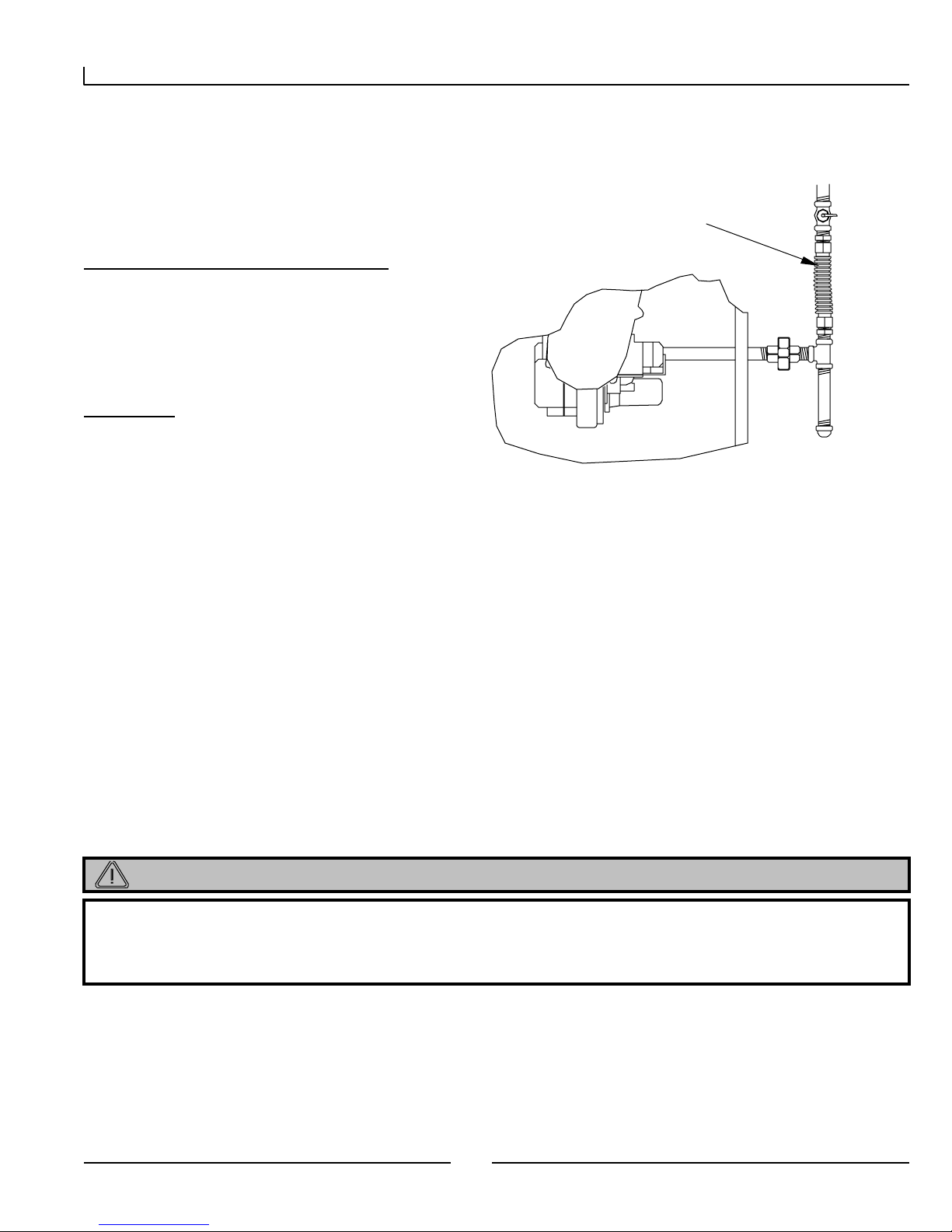
7.1.1 M atrix DHW without Stor age
The Matrix will provide domestic hot water
conti nuo usly w hen flow is sensed by the fl owswitch. This method is the most efficient means
of heating water by allowing the boiler to operate
at a lower retur n water temperature, thus
increasing combustion efficiency.
For the stat e of Massachuset t s
Comb i must
be field equipped
with 150 PSI
relief va l ve as
shown (not
provided)
Relief
Valve
C
H
M
7.1.2 M atrix DHW with Storage
In larger demand
applications, a storage tank
may be added. In this
application the Matrix will
provide hot water to
maintain temperature in the
storage tank. The aqua-stat
initiates the pump which
activates the optional flow
switch. The flow switch
provides the call at the
boiler. In this application
the flow switch ma y be
replaced by an isolation
relay activated by the aquastat. The nor mally open
contact can then provide
24V to FS on the Matrix.
Thermostatic
Mixing Valve
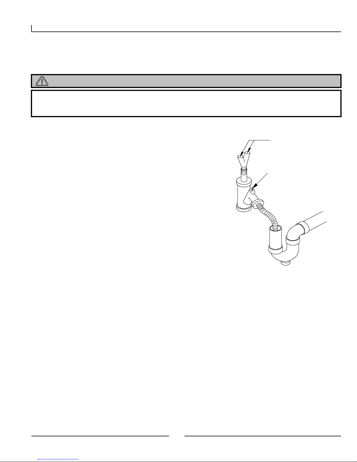
Figure 7.2 DHW Pipin g with Stora ge
Ch ec k V alve
No elbows within
2” of flowsw it ch
either end
Domestic
Wate r Ou t
Domestic
Wate r Ou t
Hot
Tank
Return
Tank
Supply
Figure 7.1 DHW Pipin g
Domestic
Wate r In
Cold
Flow
Cold
Switch
Hot
Domestic
Wate r Ou t
Ch ec k V alve
Cold Water
Supply
No elbows within
2” of f low sw itch
(either end)
Plate H eat
Exchanger
Drain for
Cleaning
Thermostatic
Mixing Valve
Thr o ttling Valve
Flow Switch
(Optional)
Plate H eat
Exchanger
For the stat e of Massachuset t s
Comb i must
be field equipped
with 150 PSI
relief va l ve as
shown (not
provided)
Relief
Valve
C
H
M
IMPORTANT
Follow mount ing instr uct i ons pr ovided with the f low switch.
25
Circulator started
by tank aquastat
Drain for
Cleaning
Page 26

Matrix Installation a nd Operatio n Instructions
8.0 W IRING
8.1 Field Wiring to M a t r ix
All wiring mus t be in accordance with the Canadian Electrical code, CSA C22.2, and any applicable local codes. Ensure that the
wiring is in accordance with this manual.
The boiler must be electrically grounded in accordance with the National Electrical Code ANSI/ N FPA 7 0, or local codes, and/or
the Canadian Electrical Code CSA C22.1.
All connections to the Matrix are made at the terminal board provided. This termi nal board can be found on the left side of the
appliance just above the plumbi ng connections. The following connections are available, and provide different functions according
to which inputs are energized.
Fig ur e 8.1 Low Volt age Connections Fig ur e 8.2 120V Connecti ons
Matrix
Terminal Strip
Hydronic Heat
End Switch
Domestic Hot Water
Flow Switch
De-Humidistat
End Switch
Matrix
Electrical Box
Typical Thermostat
RC
24V Hot - R
Space Heat - W
Cooling - Y
Circulating Fan - G
24V Common - C
Optional Stage 2 Heat - W2
WARNING
THE MATRIX TERMINAL STRIP IS FOR LOW VOLTAGE (MAX 24 VAC) AND LOW LOAD (MAX 1 AMP)
CONNE CT IONS. ANY E LECT RIC AL LO ADS I N E XCE SS OF 2 4 VAC O R 1 AMP M UST BE ISO L ATE D U SIN G
RELAYS. F AIL URE TO FOLLOW THESE INSTRUCTION C AN RESU LT IN FIRE.
ATTENTION
1. Before providing 120 Volts to the appliance, do a continuity check between all wires and ground to
make sure that ther e ar e no electr ical leaks that could damage the M at r ix circuitry.
2. Before providing 120 V olts to the appl iance, do a polar ity check of the line a nd neutral wires, line must
be connected to black and neutr al must be connect ed t o wh it e.
3. Do not use magnet ic tip screwdriver near the M atrix control boards.
4. Ensure t hat t he wiring for t he plenum and outdoor air sensor is not dam aged or gr ounded.
5. Caution: Labe l all wires prior to d isconnecting the m when ser vicing cont ro ls. Wiri ng errors can cause
improper and dangerous operat ion
26
Page 27

Matrix Installation a nd Operatio n Instructions
8.2 Mat r ix Factor y W iring Schematic
8.2.1 Boiler Control Wiring
Consult diagram on unit for exact wire routing.
27
Page 28

Matrix Installation a nd Operatio n Instructions
8.2.2 Fan Cont r ol Wiring
Consult diagram on unit for exact wire routing.
28
Page 29

Matrix Installation a nd Operatio n Instructions
9.0 CONTROL SETUP
The Matrix used two devices to control the functions required by the Matrix. The Matrix Boiler Control (red face) controls and
ensures the safe operation of the boiler functions of the Matrix much the same as the Sentry 2100 does in the Trinity products. The
Matrix Fan Control (blue face) controls all of the operation and safety func tions related to air handling and hot water dispatching.
The fan controller controls the forced air modulation, ventilation, as well as priority of domestic hot water and secondary heating
systems.
ATTENTION
T he Mat rix Boiler Con tro l (S entry) is different from the Sentry cont roller used on any othe r NTI
products and is NOT INTERCHANGEABLE.
9.1 Controller Displa ys
9.1.1 M atrix Boiler Contr ol (Sentr y) Display ( Red Face Plate)
The Matrix Boiler Control communicates to the user what is happening in the system by using an LED display and a series of LED
indicators.
Burner/Bruleur
Forced Air Demand
Hydronic Demand
DHW Demand
Gas Input
Air
Boile r
Boile r
Setpoint
Temp
TCA
9.1.2 M atrix Fan Control Display (Blue Face
Plate)
Temp
Val ue
Matrix Boiler Control
Table 9.1 Matrix Boiler Control Display
Display Description
Burner/Brûleur
Indicates that the igni t ion system is
activated
Indicates a call for for ced air heat –
Forced Air
Demand
Please note. There may sti l l be a call
for for ced air heat even when
thermostat is satisfied (off).
Hydronic Demand
DHW Demand
Boiler Temp
Boiler Setpoi nt
Air Temp
Indicates a call for hydronic heat
Indicates a call for domestic hot water
When illuminated, display is show i ng
boiler water temperature
When illuminated, display is show i ng
boile r w ater set point
When illuminated, display is show i ng
outdoor t emperat ur e
When illuminated, display is show i ng
Gas Input Value
current ga s input value. See chart to
determine inp ut rate.
Space Heat
Cooling
DHW
Hydronic
Recirc.
NOCOMNC
HighHRV On Defrost
Humidity
Matri x Fan Control
29
Table 9. 2 Matrix Fan Cont r ol Di sp l ay
Display Description
Space Heat
Cooling
DHW
Hydronic
ReCirc.
Indicates a call for forced air heat i ng
Indicates a call for cooling
Indicates a call for domestic hot water
Indicates a call for hydronic heat
Indicates a call for continuous
circulation/ventilation
HRV On Indicates the HRV is ventilating
Defrost Indicates the HRV is in defrost mode
High Humid it y Indicat es a c a ll for hig h ventila tio n of HRV
Page 30

Matrix Installation a nd Operatio n Instructions
N
9.2 Oper at ion and Set- up
The Matrix employs a pneumatic modulation system. This modulation system increases or decreases the velocity of the combustion
blower, to meet the demand for heating. The gas valve senses this change in blower pressure and introduces the required amount of
gas to ensure correct combustion. The Sentry reads the boiler water temperature, compares it to the set point, and adjusts the burner
firing rate accordingly by varying the speed of the combustion blower.
The boiler control reacts to two main inputs: A-C and T-C. The following table shows the response by the boiler control to the
different states of each input. For more information on ‘RESET MODE’ see section ‘9.3 Outdoor Sensor Operation’.
Table 9.3 Conventional vs. Outdoor Reset Mode
Standby/Storage
Mode
Condition
MODE
Set Point - 160°F SP
Burner On - 140°F SP
CONVENTIONAL
Burner Off - 180°F 210°F 210°F 210°F HYD + 10
Heat Circ. Off On On On On On On
Condition
MODE
Set Point - 160°F SP
RESET
Burner On - 140°F SP
Burner Off - 180°F 210°F 210°F 210°F HYD
Heat Circ. Off On On On On On On
Storage
Off
Standby/Storage
Storage
Off
ote 1. SP (Setpoint) received from Matrix Fan Controller.
Mode
Storage
On
Storage
On
Primary
Forced Air
Call (W1)
Heat (W1)
Note 1
HI
Note 1
HI
Primary
Forced Air
Call (W1)
Heat (W1)
Note 1
HI
Note 1
HI
Auxiliary
Forced Air
Call (W2)
Aux Heat
(W2)
Note 1
Note 1
Auxiliary
Forced Air
Call (W2)
Aux Heat
(W2)
Note 1
Calc.
Note 1
Calc.
Shared Call
Forced
Air/Hydronic
Shared (W1/W2
and H)
Greater of SP/ HI
and HYD
Greater of SP/HI
and HYD
Shared Call
Forced
Air/Hydronic
Shared (W1/W2
and H)
Greater of SP/ HI
and HYD
Calc.
Greater of SP/ HI
and HYD
Calc.
Calc.
Calc.
Hydronic
Demand (H)
Hydronic Call
HYD H2O+30
HYD-DIF H2O+30
Hydronic
Demand (H)
Hydronic Call
HYD
HYD
H2O+30
Calc.
-DIF H2O+30
Calc.
+ 10
Calc.
DHW
Demand
(FS)
Domestic
Only
°F
210
DHW
Demand
(FS)
Domestic
Only
°F
210
9.2.1 Setting Matrix Boiler Control (Sentry)
Programming is accomplished by a series of three push buttons located on the bottom side of the control. (Function,
enter the programming mode, press the function key once. To scroll through the various menu options depress
displayed. To alter the value press Function once, and the current value will be displayed, then use
the desired value is obtained. To enter the selected value press Function, which will return to the menu. When all desired values are
selected, scroll to the RUN menu, and press Function, which e xits the Programming Mode and initiates normal operation. A safety
feature has been added to ensure that if the control is left in the Program Mode, the unit will turn off if left in program mode longer
than 30 seconds without receiving an input. Press Function once to continue programming or to start boiler operation.
30
↑
and ↓). To
↑
until the menu is
↑
for up, and ↓ for down, until
Page 31

Matrix Installation a nd Operatio n Instructions
Table 9. 4 Matrix Boiler Contr ol Pr ogr am mi ng
Menu Level Description
Main Value Typical Settings
Program Mode - When Run is displayed controller
RUN
H2O 80-190 DHW Setpoint 160
HYD 80-200 Hydronic Call Setpoint
HI 80-200
DIF 1-40
RES 70-190
SFS 75-100 Starting Gas Input Value 80
HFS 100-240 Maximum Gas Input Value 240
LFS 46-100 Minimum Gas Input Value 48 (min 46)
FrE ON/OFF
Sto OFF-24
To start the control operation, you must return to RUN on the menu, and press Function. Normal
is in ‘Prog’ mode. Arrow up or down to scroll
through menus
Auxiliary Heat Setpoint – prior to outdoor reset
adjustment
Differential Setting - Applies only to Hydronic Only
setpoint. Temperature difference below setpoint at
which burner w ill re-light.
Sets Outdoor Reset Curve Slope – See
Determining Reset Temperature for m ore
information.
Freeze Protection – Operates burner and circulator
if temperature drops below 40ºF.
Storage Feature Timer – Length of time in hours
storage feature will keep boiler hot.
operation will begin. Controller will return to RUN mode if no button is pressed for 2 minutes.
100-120 Infloor (High Mass)
140-160 Infloor (Low Mass)
140-160 Fan Coil
190
10
85
ON
4
9.2.2 Set t ing M at r ix Fan Contr ol
Just as the Matrix Boiler Controller controls all of the operation and safety functions of the boiler, the Matrix Fan Controller,
control s al l of the op eration a nd sa fe t y func tions relate d to air ha ndling and ho t w ater dispatc hing. The fa n control ler controls the
forced air modulation, ventilation, as well as priority of domestic hot water and secondary heating systems.
Table 9. 5 Matrix Fan Cont r ol Pr ogr am mi ng
Menu Level Description
Main Sub Value
RUN
OFF HRV M ode – Always off unless call for high ventilation (DH)
HRV
HEA
COO 40-160 Cooling Flow *10 = CFM (400-1600) cfm
BAL
H2O 100-160 Sets DHW Target Tem perature, recomm end 120-130ºF
To start the control operation, you must return to RUN on the menu, and press Function. Normal
ON
PF1 Heat Profile 1 300/800 cfm 66,000 Btu/h max.
PF2 Heat Profile 2 400/1000 cfm 83,000 Btu/h max.
PF3 Heat Profile 3 500/1200 cfm 92,000 Btu/h max.
SCL 30-100
ECL 30-100
SCH 30-100
ECH 30-100
SOL 30-100
EOL 30-100
SOH 30-100
EOH 30-100
When Run is displayed, controller is in ‘Prog’ mode. Arrow up or down to
scroll through menus
HRV Mode – Continuous Ventilation. HRV w ill exchange air at low
ventilation rate during a call for forced air heat (W1 or W2) or continuous
circulatio n (G). Will increase to h ig h v e n tilation rate with a high
ventilation call (24vac @ DH)
HRV Balancing – (see HRV section for more details)
operation will begin. Controller will return to RUN mode if no button is pressed for 2 minutes.
31
Page 32

Matrix Installation a nd Operatio n Instructions
9.3 Out door Sensor O per at ion
The outdoor sensor is connected to the termi nal board on the left side of the matri x. The two terminals are labeled ‘OUTDOOR
SENSOR’.
Fig ur e 9.1 Outdoor Sensor Connection
When the Outdoor sensor is not used, or the outdoor temperature is
below 0°F, the Matrix operates at a boiler water temperature equal to
the HYD or HI setpoint during a call for Hydronic or Emergency
Heat respectively. When the sensor is used and the outdoor
temperature is above 0°F, the Matrix boiler control automa tically
reduces the operating temperature of the boiler during those calls.
Using the following formula, the control factors in the current
outdoor temperature, control setpoint (HYD or HI), and the RES
(reset) setpoint, in determi ning the appropriate operating water
temperature.
Figur e 9.2 Outdoor Reset Calculation
Formula:
Operating Temperature = {(RES – Outdoor Temp) x (HYD – RES) / RES} + RES
Note: Substitute HYD fo r HI du ring a call for Emergency He a t.
Example:
• There is a call for Hydronic heat; therefore the control uses the HYD programmed
setting.
• The HYD is programmed to be 160°F.
• The RES is programmed to be 85°F.
• The outdoor temperature is 40°F.
Operating Temperature = {(85 – 40) x (160 – 85) / 85} + 85 =
The following c h a rt illu s tr a te s th e e ffe c t o f c hanging outdoor tem perature on the boiler operating
temperature for the above ex am ple.
125°F
Reset Curve for Res=85 & Setp oint=160
170
150
130
110
90
Water Temp. (F)
70
-10 0 10 20 30 40 50 60 70 80 90 100
Ou td o or T emperatu re (deg .F)
32
Page 33

Matrix Installation a nd Operatio n Instructions
10.0 MATRI X BLOWER OPERAT ION
10.1 Forced Air Heating
The Matrix forced-air heating module is a step-modulated system, which provides varying heat output rates by adjusting air flow
and water temperature through a fan coil.
Table 10.1 Fancoi l O utput Chart
Heat Profile 1 (PF1) Heat Profile 2 (PF2) Heat Profile 3 (PF3)
Heating
Stage
1 300 115
2 425 120
3 550 124
4 675 128
5 800 132
6 800 142
7 800 152
8 800 161
9 800 170
10 800 180
Cfm
Set Point
(°F)
Air Temp
(°F)
Btu/Hr O u t Cfm
109 12,000
111 18,000
112 24,000
113 30,000
114 36,000
121 42,000
128 48,000
135 54,000
141 60,000
148 66,000
Set Point
(°F)
400 115
550 120
700 125
850 130
1000 135
1000 145
1000 155
1000 165
1000 175
1000 185
Air Temp
(°F)
Btu/Hr O u t Cfm
109 15,500
111 22,600
114 29,700
116 36,800
118 43,900
125 51,000
132 58,100
139 65,200
146 72,300
154 79,000
Set Point
(°F)
500 115
675 122
850 128
1025 135
1200 140
1200 150
1200 160
1200 170
1200 180
1200 190
Air Temp
(°F)
Btu/Hr O u t
108 18,500
112 26,700
115 34,900
118 43,100
120 51,300
126.5 59,500
133 67,700
140 75,900
147 84,100
150 92,000
what is shown
A`tual Output rates may vary from
Example. At stage 4 (Profile 1) the Matrix provides 675 cfm across the fan coil, which is receiving 128°F water from the boiler. The
coil then supplies plenum air at 113° F or ~30,000 BTU/hr. (1.08x675x(113-72)=30,000)
On an initial thermostat call (24VAC @ W1), space heating begins by providing heat at stage 3 (~24,000 BTU/hr) (if hydronic heat
is also calling (24VAC @ H) heating will begin at stage 1) and so long as the thermos tat is not satisfied, incrementally increases to
a maximum of stage 10 (~66,000 BTU/hr). When the thermos tat becomes satisfied, an average of the heat output rate during the
call is calculated. The boiler remains lit and the space heat output begins an incremental decrease in heat output rate beginning with
the stage just below the calculated average and ending with either the thermostat re-calling or if the thermostat never re-calls, the
outp ut rate decreases to mini mum stage after whic h the boiler shuts off.
If the thermostat re-calls prior to the minimum heat stage, a new calculated average of the thermostat off cycle is calculated and the
boiler again begins an increasing ramp, only this time it begi ns at the calculated stage and not necessarily at the minimum stage.
This computation “hunts” for the heat loss of the dwelling based on the reaction of the thermostat to the rise and fall of the space
temperature and the heat cycle rate of the thermostat.
If at any time the plenum temperature exceeds 160°F, the boiler will stop supplying heat until the temperature in the supply plenum
drops below 140ºF, during which ti me an AL2 error message will be displayed.
ATTENTION
The burner wi ll r ema in on and t he M at r ix wil l provide heat when the thermostat is of f . This is norma l and i s
required to pr ovide constant ef f ici ent heat .
Call for Heat (24VAC @ W1): Normal Thermostat call, Matrix operates as a step-modulating furnace as described above. If
HRV set to ‘ON’, HRV will operate at the low (continuous) ventilation rate.
33
Page 34

Matrix Installation a nd Operatio n Instructions
Call for Auxiliary Heat (24 V AC @ W2) : When calling, furnace will provide heat at a stage 10 output rate. With a call for
auxiliary heating the Matrix will function as a single stage, full fire appliance. This means the burner will come on with a
thermostat call and go off when the call is satisfied. If HRV set to ‘ON’, HRV will operate at the low (continuous) ventilation r ate.
Outdoor Sensor: The auxiliary heating function
Fig ur e 10.1 Fan Funct ion Connections
(24VAC @ W2) will utilize the outdoor sensor if available.
The outdoor reset function is not used for W1 heating. This
function is also active during a hydronic heat demand
(24VAC @ H).
Plenum Sensor: The Matrix is equipped with a plenum
temperature sensor that must be field installed in the supply
plenum and wired to the fur naces external terminal strip.
When installed the Matrix fan control displays the plenum
De-Humidistat
End Switch
temperature and will use it to detect problems in the supply
of heat to the space.
Call for Circulating Fan (24VAC @ G): Matri x
operates at the minimum air circulation rate for the heat
profile selected (300/400/500 CFM). If HRV is set to ‘ON’
(See 8.2 Fan Controller), the HRV will ventilate at the low
(Continuous) ventilation rate.
Call for Dehumidification (24VAC @ DH): Matrix
operates at the minimum air circulation rate for the heat
profile selected (300/400/500 CFM). HRV will ventilate at
the high (Override) ventilation rate.
Typical Thermostat
RC
24V Hot - R
Space He at - W
Cool in g - Y
Circul ating Fan - G
24V Common - C
Optional St age 2 Heat - W2
Call for Cooling Fan ( 24VAC @ Y): Matrix operates at the prescribed air circulation rate (COOx10 CFM – See 8.2 Fan
Control). HRV will not operate during a call for cooling unless there is a concurrent call for DH – Dehumidification or G –
Continuous and HRV is set to ON.
10.2 Duct Sizing
When sizing ductwork, a maximum flow velocity of 800 fpm is
desired. Table 11 shows common duct sizes at specified flows. The
maximum flows that can be expected are shown in Table 10.3. It is
important to maintain the return plenum pressure as low as possible.
Keeping this ductwork as free flowing as possible will offer more
supply static pressure to overcome A/C coils, closed registers etc while
mai ntaining cons tant flow.
Any additional filtration, humidification, or de-humidification
equipment should be installed external to the return or supply ducts so
not to create additional restriction.
Table 10.2 Duct Size vs. Air Flow
Airflow
(CFM)
1600
1200
1000
800
Area
(sqft)
2 24x12 20x16
1.5 24x10 20x12 18x12
1.25 20x10 18x10 16x12
1 18x8 16x10 12x12
Based on 800 fpm max airflow velocity
Duct Sizing
(inches)
Table 10.3 Maximum Air Flow Rates
Fan Control Se tt i ng
Heating
(HEA)
160 max .35 inwg 1600
160 max .6 inwg 1500
160 max .75 inwg 1400
120 (3 Ton) 1200
80 (2 Ton) 800
PF3 No Coolin g <1 inwg 1200
PF2 No Coolin g <1 inwg 1000
PF1 No Coolin g <1 inwg 800
Example #1
profile of PF2 selec t ed. Maximum airflow will be
1000 cfm.
Example #2 Coolin g set t o 800 cfm for 2 tons of
coolin g with Heatin g profil e of PF3 selected.
Max imum airflow will be greater of cooling or heating
fun ction . Maximum 1200 cfm.
*Measured from return plenum to supply plenum prior to A/C coil.
ECM motor can produce near constant flow provided horsepower or
maxi mu m speed of motor is not exceeded.
Cooling
(COO)
No cooling fun ct ion w ith Heating
ESPmax* CFM
34
Page 35

Matrix Installation a nd Operatio n Instructions
11.0 HEAT RECOVE RY VENTI LATI ON
11.1 Ventilation Needs
With the evolution toward more energy efficient, tighter homes, air quality problems have increased. With less natural ventilation
pollutants such as pet dander, humidity, tobacco smoke and wood ash now become trapped inside the home. Mechanical
ventilation is the process of exhausting the polluted air from the space and replacing it with fresh air from outside. The amount of
ventilation required varies from home to home and can be estimated using one of the following methods:
11.1.1 Room Count Ca lcu lation
Living Space
Master Bedr oom x 20 c f m (10 L/ s) =
With Basement x 20 cfm (10 L/s) =
Without
Basement
Single Bedroom x 10 cfm (5 L/s) =
Living Room x 10 cfm (5 L/ s) =
Dining Room x 10 cfm (5 L/s) =
Family Room x 10 cfm (5 L/s) =
Recreational
Room
Other
Kitchen x 10 cfm (5 L/s) =
Bathroom x 10 cfm (5 L/s) =
Laundry Room x 10 cfm (5 L/s) =
Utility Room x 10 cfm (5 L/s) =
Total Ventilation Req uireme nt (sum last column) =
Numbe r o f
Rooms
x 10 cfm (5 L/s) =
CFM (L/S) CFM Re q'd
11.1.2 Air Change per Hour M ethod
To t al cu.f t x 0.3 / 60 = Total Ventil at ion Required
Example. A 25’ x 40’ house with basement
1000 sqft x 8’ high x 2(main floor and basement) = 16, 000 cu.ft
16,000 x .3 air changes per hour = 4,800 cu.ft/hr
4,800 cu.ft/hr / 60 = 80 cfm
80 cfm is ventilation requ ireme nt
35
Page 36

Matrix Installation a nd Operatio n Instructions
n
11.2 T ypes of Installation
There are two basic methods of installing the ventilator in the Matrix:
Exhaust at the sour ce. Stale air is drawn from the kitchen and bathrooms.
External Ducting to be 6”
Warm Air
Supply
Col d A ir
Return
Stale Air From
Kitchen and
Bathroom
insul at ed with Vapor Barrier
6’-0” min
18” min
Exhaust from the return (Simplified System). Stale air is drawn from the return plenum.
Warm Air
Col d A ir
Return
Stale Air From
Cold Air Return
(Connec tion to be 4ft f r om
where return plenu m attaches
to Matri x)
Supply
External Ducting to be 6”
insul at ed with Vapor Barrier
6’-0” mi
18” min
36
Page 37

Matrix Installation a nd Operatio n Instructions
Attac
Supplied Tubing to
IMPORTANT
When using the Simplified System method, exhaust connection to the return must be 4’ from where the
return connects to the Matrix.
IMPORTANT
All main HRV ductwork t o be 6” r ound.
Exterior connections are to be insulated and include a vapor barrier.
11.3 Damper Box
Included in the installation kit is a damper box. This
damper box elimi nates the infiltration of cold outside
air when the HRV is off or in defrost mode. It is to
be installed with the actuator on the top side and
screw to the Matrix using the four screws provided.
Damper Box with Collar Inst alled
11.4 Condensate Drai n
Condensation from defrost will collect in the
ventilator and drain from the sloped drain pan.
This condensation must be evacuated from the
unit. The condensate tubing provided must be
routed through the hole in the side of the
appliance and attached to the 90° elbow directly
underneath the ventilation module. From there
the condensate tube must be emptied into a
suitable floor drain or if necessary the emptying
drain must have a trap to prevent the infiltration
of toxic gases.
This En d to Appropriat e
37
h End of
Page 38

Matrix Installation a nd Operatio n Instructions
11.5 HRV Balancing
The HRV must be balance properly in order to operate at maximum efficiency and avoid problems.
The balancing process ensures the volume of fresh air from outside is equal to the amount of stale air being expelled from the ho me
over all air handler conditions. A variation of 10% is acceptable with the greater volume being stale air drawn from the home.
The Matrix uses motor speed to balance airflows. This method of balancing provides quieter operation and reduced energy
consumption over the traditional balancing damper approach.
Flow is measured with the use of a Magnehelic (0-.25 inwg range) and an airflow grid, flow collar or “Flow Measuring Station”.
NTI offers an airflow grid, PN: 83554, that is designed to be installed in a 1” hole located in a 6” duct. It is important that the flow
grid be the same size as the ductwork, and be installed according to the manufacturers instruc tions. Typically a straight run of 18”
on either side of the flow grid is adequate to avoid false readings. It is helpful if a flow grid is installed in each of the supply and
exha ust duc ts.
Procedure.
Attach the upflow port of the flow grid to the positive pressure port of the Magnehelic and the down flow port to the negative port.
Zero the Magnehelic.
Begin by selecting the heating profile required in the Matrix Fan Controller ‘HEA’ menu. Refer to the heating section of the
manual for more explanation. The heati ng profile selected dictates the air handler blower speeds and is important to the proper
functioning of the HRV. Every time the heating profile is changed the HRV will require re-balancing.
Once the heating profile is selected, advance to the ‘BAL’ menu. By pressing the ‘FUNCTION’ button you will enter the balancing
mode of the HRV. Press the up arrow button and advance through the menus until you reach the ‘EOH’ menu item. By pressing
the ‘FUNCTION’ button you will enter the ‘EOH’ menu. A number will appear. You will notice the HRV start, if it is not already
running, and the main blower of the air handle will come up to speed. The number on the display represents the speed of the HRV
fan in percentage. In the case of ‘EOH’ the number shown represents the speed of the exhaust ‘E’ fan during a call for hi gh
ventilation ‘O’ (override) while the air handler blower is running at the high ‘H’ heating speed. The maximum speed setting is
100%, the minimum 30%. Adjust the speed up or down until the desired flow rate is achieved. Table 11.1, on the following page,
has been provided to help in explaining the different settings.
Complete the table adjusting each of the setting to the HRV Ventilation Rate provided. These rates are a guideline only and can be
adjusted to meet the specific application.
-Note- When adjusting the exhaust speeds, the supply fan will increase to full speed.
When the balancing is complete, the HRV will maintain balance at any ventilation rate during any air handler blower condition.
This is a unique feature of the Matrix and is essential in providing efficient and adequate ventilation in this integrated system.
ATTENTION
The HRV balance must be checked and if necessary rebalanced every time the Heating (HEA) setting is
changed, or if there is chan ge to the system which wo uld sig nificantly change the static pressure at th e
return plenum or the ext er ior duct s t o t he HRV.
38
Page 39

Matrix Installation a nd Operatio n Instructions
Figure 11.1 Sample Balancing Setup
Stale
Exhaust
Fresh
Supply
6” Flow Measur em ent Station,
Averaging Pitot Tube, or
Pitot TransferTube
Magnehelic (0-.25 inwg)
or Digital Manometer
Table 11.1 HRV Balanci ng Table
Menu
Item
EOH
SOH
EOL
SOL
ECH
SCH
ECL
SCL
HRV Exhaust at Override (high ventilation) rate, balanced during High air
circulation rate (800/1000/1200CFM).
HRV Supply at Override (high ventilation) rate, balanced during High air
circulation rate (800/1000/1200CFM).
HRV Exhaust at Override (high ventilation) rate, balanced during Low air
circulation rate (300/400/500CFM).
HRV Supply at Override (high ventilation) rate, balanced during Low air
circulation rate (300/400/500CFM).
HRV Exhaust at Continuous (low vent il at ion) rate, bal anced during High air
circulation rate (800/1000/1200CFM).
HRV Supply at Continuous (low vent ilation ) rat e, balanced durin g High air
circulation rate (800/1000/1200CFM).
HRV Exhaust at Continuous (low vent il at ion) rate, bal anced during Low air
circulation rate (300/400/500CFM).
HRV Supply at Continuous (low vent ilation ) rat e, balanced durin g Low air
circulation rate (300/400/500CFM).
Description
39
Sample HRV
Ventilatio n
Rates
120cfm
(55 L/s)
120cfm
(55 L/s)
120cfm
(55 L/s)
120cfm
(55 L/s)
70cfm
(30 L/s)
70cfm
(30 L/s)
70cfm
(30 L/s)
70cfm
(30 L/s)
Installed
Ventilatio n
Rates
Installed
Fan
Speed
Page 40

Matrix Installation a nd Operatio n Instructions
12.0 LIGHTING BOILER
12.1 Init ial Start-Up
Ensure that the boiler is wired in accordance with this manual.
Ensure that the gas shut-off valve is turned on, and that the gas system has been fully tested for leaks.
Ensure that the system is completely filled with water, and that ALL of the air has been purged from the system.
Turn on power to the Appliance. The unit should run through a purge, and combustion should occur. (The control system has a built
in ignition retry, allowing the system to retry at least four times, before locking-out.)
Verify that the gas line pressure is 4-9”wc. for natural gas, and 9-12” wc. for propane.
Using an appropriate Oxygen or Carbon Dioxide analyzer, take a sample of the flue gas. The sample must fall within the acceptable
ranges for carbon Dioxide, which is 8% - 9.5% for natural gas, and 9.0%-10.5% for propane. If the reading does not fall within
this range, contact NY Thermal, for assistance.
Perform at least three lights in succession to ensure proper operation.
After the three successive lights, unplug the flame probe, and allow the unit to cycle again. Ensure that it tries to light, and locks out
on safety reset. Once you have successfully activated the flame safety system, replace the wire on the flame sensor, and reconfirm
proper lighting.
WARNING
IF YOU DO NOT FOLLOW THESE INSTRUCTIONS EXACTLY, A FIRE OR EXPLOSION MAY RESULT
CAU SING PROPERTY DAM AGE, AND LOSS OF LIFE.
For Your Safet y , Read bef or e oper at ing
This appliance does not have a pilot. It is equipped with an ignition device that automatically lights the burner. Do not try to light
the burner by hand.
BEFORE OPERATING, check all around the appliance area for gas. Be sure to check next to the floor, as some gases are heavier
than air, and will settle on the floor.
Use only your hand to turn gas knobs, never use a tool. Forcing the valve, or attempting to repair it can cause fire or explosion.
Do not use the appliance if any part is under water.
12.2 Re-Lightin g Unit
Stop and read these instructions very carefully.
Set the thermostat to the lowest setting, and then turn off all power to the boiler.
This appliance does not have a pilot. It is equipped with an ignition device that automatically lights the burner. Do not try to light
the burner by hand.
Turn the gas shut-off valve to the off position, and then remove the front cover.
Wait five (5) minutes to clear out any gas. Then check for gas, including near the floor. If you smell gas “Stop” and follow “B”
above. If you don’t detect any gas proceed to the next s tep.
Turn the gas shut-off valve to the on position, wait an addition five (5) minutes and check for gas.
Replace the front cover.
Set the thermostat to the highest setting, and then turn on all power to the boiler.
Ignition sequence is automatic, combustion will occur after a brief fan purge. Ignition will retry 3 times.
If ignition does not occur, “Turn off the gas a nd electricity to the boiler” and contact a professional service technician, or gas
supplier.
12.3 T ur n Off Appliance
Set the thermostat to the lowest setting, and then turn off all power to the boiler.
Turn the gas shut-off valve to the off position.
40
Page 41

Matrix Installation a nd Operatio n Instructions
13.0 T ROUBLE SHOOTING
This section is intended to assist the service technician in detecting and correcting common errors. The Matrix Boiler and Fan
Controls are equipped with an internal diagnostic system that verifies control operation. The following series of error codes has
been developed to aid in diagnosing control problems:
Symptom Detected Problem Solution
1. If the boiler is extr emely hot check for adequat e water pressure and
circula tion, contact NTI for assistance.
2. If not hot, check for sources of groundin g or shorting at the Water Sens or
electr ical connections, check wiring from Sen sor to Boiler (Red) Control.
3. Replace Water Sensor if the resistance is not in the correct range. (See
th ermister resist ance charts in Figur es 13.1 and 13.2)
See ER1
1. Check wiring to Water Sensor for open circuits or shorting to ground. (Note:
ER3 will be displ ayed if temperatur e sen sed is less then 0°F.)
2. Replace Water Sensor if the resistance is not in the correct range. (See
th ermister resist ance charts in Figur es 13.1 and 13.2)
1. Res et power, if error goes away the problem is intermitt ent and was likely
caused by a tripped limit th at has automatically reset , check f or adequate
water pressur e and fl ow rate. Allow the boiler to cycle and verify proper
operation inclu ding outlet water temperatur e and flue temperatur e. If
operation is unsucces sful and the err or reoccurs:
2. Mat r ix boiler s are equipped with a low water pressure switch on the boiler
return that requ ires a minimum of 10PSI to complete the 24VAC ignition
circuit . Ensure the field-in stalled pres sur e gauge is reading a minimum of
12PSI. Replace water pressure switch if plumbing and pres sure is correct
and if it measur es an open circuit.
3. Chec k f or continuity through the 24VAC limit wiring and manifol d and stack
limits, replace limits or wiring that are not a closed circuit.
1. Res et the ER5 error by resetting the power or cycling the DHW call. Check
for pr oper operat ion of the DHW call.
2. Matrix units are provided with a DHW flow switch; ensure it is not sticking in
th e closed position wh en there is no DHW flow. If so, remov e it and free it of
any debr is and check for proper oper ation, replace if necess ary (water
shoul d be filtered prior to flow switch.
There is a problem in the ignition sequ ence; it could be caused by a faulty igniter,
flam e sens or, gas valve or improper line pressur e or combustion. Check ignition
sequence to determine which compon ent is not functionin g. (Sentry will retry
ignition sequence 1 hour after ER6 code originally occurs or if c ontrol is reset)
Indicates that the Sentry control has lost communication with an internal
processor, c ont act NTI.
1. En sur e th e vinyl tubes, connect ed between the air switch and the ports on
th e inlet pipe, are in the proper locations. Negative side of switch connects
to the port on the 1-1/2” PVC elbow.
2. Chec k f or block age on the intake and exhaust vents.
3. If fan is running the air switch may be faulty, ensure it is set at 0.2”wc.
4. If fan is not running, check 120V wiring to blower, if ok remove low voltage
harn ess from blower, if blow er fails to start, replace blow er, if blower does
start the pr oblem may be with blower or Sentry control.
1. Does the combustion fan run continuously at full speed while the error is
display ed? If so check for 24V from transf ormer, al so check transformer
fu se. If 24V is present ch eck th e low voltage wiring from Sentry to
combu st ion blower, replac e Sentry or Blower.
2. Is the combustion fan off? If so check for water in the air switch and air
switch tubes, replace switch if necessary.
3. Check venting termination with required venting described in manual.
Con tact NTI.
Check f or 120V between termin als L1 and L2 at Sentry.
If 120V exists turn power off and remove line voltage harness from Sentry. Then
check for resistance between L1 and L2 of control, if the circuit is open (O.L) th e
intern al fu se has blown. Check for shorts in wires leading to circulator prior to
replacing controller. (Not e: If fuse is good the circuit will read between 300 and
400 Ohms.)
If 120V not present, check wirin g and for 120V at source.
ER1
ER2
ER3
ER4
ER5
On Display
ER6
ER9 Internal Contr oller Faul t
Boiler Control (Red Face)
ASO
Air Switch
Open
ASC
Air Switch
Closed
Sentry
Controller
Locks-up
Display Goes
Blank
“Water Temper ature Excessi ve”
Sentry has sensed a water
temper atu r e in excess of 250ºF at
the Water Sensor.
“Wate r Sens or Shor t Cir cui t ”
Sentry has sensed a short circuit
in the Water Sensor circuit.
“Water Sensor Open Cir cuit”
Sentry has sensed an open circuit
in the Water Sensor circuit.
“24V Limit Error”
Sentry has sensed a lack of 24V
on the outlet of the Sentry burner
relay (B1). Lockout lasts for one
hour before automatically
resetting.
“DHW Tim e- O ut ”
The Sentry has sensed th at the
DHW call has lasted longer then
2.5 hours, thus removing priority
from the DHW call.
“Flame Lock Out”
Sentry has sensed a lack of 24V to
th e gas valve during operation or a
Fenwal ignition lockout.
Th is is d is p layed wh en the bo iler is
expect ing th e air switch to be
closed by a different ial pressur e
gener at ed when the combust ion
blower turn s on. It can occur
moment ar ily durin g normal
operation . A probl em is indicated
wh en ASO is displayed
continuously.
This is displayed when the boiler
has turned th e blower off and is
expect ing th e air switch to be
open. It can occur momentarily
dur ing norm al operation . A
problem is indicated wh en ASC is
displayed continuously.
Excessive noise, current, or
voltage s pikes in the 120V power
supply.
No power to contr ol or control
failure
41
Page 42

Matrix Installation a nd Operatio n Instructions
Fan Controller (Blue Face)
Fenwal
Symptom Detected Problem Solution
AL1
AL2
Communication Error with HRV
Plenu m Temperatu r e Limit of
160ºF Ex c eeded
‘Boiler Control Error’
AL7
AL8
(& Blower Off)
Fan controller has failed to receive
run statu s from Boiler Control.
‘Furnace Blower Error’
Blower has failed to meet a
minimum speed.
‘Furnace Blower Error’
AL8
(& Blower On)
Control has failed to sense that the
blower h as reached a minimum
speed.
‘PSC‘
‘Plenum Senso r Circu it Closed’ 1. Check for chaffed w ires on plenum sensor.
‘PSO‘
F3.2 Flashing
Two Flashes
on Fenwal
‘Plenum Senso r Circu it Open’
Lack of 24 V at fan controller
The Fenw al controller thinks that
there is a flame prior to ignition.
Indic a te s Igni ti o n Loc k o u t.
Three
Flashes on
“I gnition L oc k out”
Fenwal
1. Ch eck wiring connections between HRV and Fan Controller.
2. Ch eck door switch on HRV.
3. Cy cle power to appliance; contact NTI.
1. If plenum is hot, check operation of blower fan; contact NTI.
2. If plenum is not h ot, check plenum sensor and wir ing for shorts or damage.
3. Remove plenum sensor, PSO should be displayed, if so replace plenum
sensor , if not inspect wiring from Term inal Strip to Fan Control. Replace Fan
Control if necessary.
1. Ch eck for error code on Boiler Control.
2. Ch eck c ont r ol wiring from Boiler Contr ol to Fan Control (Pins 17 and 18 on
Fan Contr ol – See wiring schematic in Section 8.2).
1. Ch eck for 120V to blower; ensure door switches are makin g the circuit.
2. Ch eck wiring from Pin 6 at Fan Con t r ol (white wire) to Pin 15 at blower
motor.
3. Ch eck for 24VAC at blower Pin 15, if present replace blower, if not replace
Fan Contr ol.
1. Ch eck wiring from Pin 5 at Fan Con t r ol (black wire), to Pin 16 at blower
motor.
2. Ch eck for 3-5VDC at blower Pin 16, if present replace blower, if not replace
Fan Contr ol.
1. Ch eck for proper connection of plenum sensor to terminal strip.
2. Ch eck for broken plenum sensor wire.
1-Check/R epl ac e 2A fuse – blown fuse indicates 24V supply shorted to ground, or
excess iv e load.
If the combustion sequence is normal, and there is no flame prior to ignition, the
Fenw al control is defective, and must be replaced.
If the condensat e dr ain gets blocked, the boiler will become flooded and term inat e
operation as the flam e rod becomes immersed. This will dam age the flame probe.
To correct , free the drain blockage, an d permanently pr ev ent it from reoccurring.
Remove and dry off th e probe. Reinstall the probe and try for ignition, if it fails to
stay l it, leave the fan run for up to three h our s to dry out the insulation and probe.
1. Reset Boiler so it will attempt to ignite.
2. Ch eck for proper operation of ignition component s . Make sure igniter glows
and gas valve opens.
3. Ch eck for proper line pressur e at gas v alve when it opens.
4. If boiler lights check for flame signal between FC1 And FC2 on Fenwal
control (If lower then 1.2 DC µAmps see “Boiler will not stay lit”).
5. Ch eck c om bust ion properties.
Burner shuts
off before
Reset calculation being used to
lower HI setting.
set-point
temperatur e
is reached
General
(and burner
light goes out)
Therm ostat is satisfied
42
If OD probe is being used, the HI se tti ng will be calculated using formula in
Section 8, adjust RES settin g as necessary.
1. If th e th ermost at demand light is turnin g off, the thermostat has sat isf ied.
2. 2-If DHW temp light is turning off; the aquastat or call for domestic has been
satisfied.
Page 43

Matrix Installation a nd Operatio n Instructions
Symptom Detected Problem Solution
1. If th e Burner light on the Sentry is going out, go to “Burner shutt i ng off”.
Boiler will
not stay lit
Boiler ba ngs
or hisses
Boiler Li ght s
General
rough or
pulsates
Fan appears
to be
creating a
noise in the
house
In dicates lack of a flame signal. In
order t o stay running the flame
.
signal mu st be at least 0.7 µAmps
Bangs or s ounds like a kettle while
burn er is running indicates
insufficient flow
Typical ly an imbal ance in the Air to
Slight vibration can cause noise in
(This is not a warranty issue)
Making a r ubbing noi se. ((This is
gas ratio
th e residence
not a warranty issue))
2. Ch eck c ondensate drain for blockage an d check the inlet piping for ingested
snow or wat er (if the flame rod gets wet, it may need to be replaced) . Check
for r esist ance from flame rod to ground, must be an open circuit (O.L), if not,
remove rod and bend it away from the burn er slightly.
3. Ch eck for proper polarity of line and neutral wiring to the boiler.
1. Ensure the plumbing is as shown in manual. Check to see if pum ps are
operatin g pr operly and water pressur e is above 15psi. This problem can
lead to boiler overheating!
2. Boiler m ay be pluggin g with scale or magnetite, cl ean with Fernox DS-40
Descaler and Cleanser (NTI PN: 83450).
3. If glycol is being used th e concentration may be to high, recommend using a
concent r ation lower then 35%.
1. Ensure that the venting lengths are in compliance with Section 3.4
2. Ensure that the line p ressure during operatio n does not drop more than 20%
from the static line pressure.
3. Momentarily remove the intake vent from the boiler durin g ignition, if unit
lights smoothly with intake vent disconnec t ed reconnect and ch eck for proper
combu st ion if unit maintain s smooth operat ion after ignition. ( See Section
5.2) Calibrate for proper combustion . If problem persists contact NY
Thermal.
4. Heat exchanger may be dirty, remove burner door and inspect, clean if
necessary.
1. Use flexible gas line to insolate the vibration noises between the gas valve
and the li ne.
2. Don’t hang gas lines from floor joists.
3. Use rubber insulators with gas line support s.
1. If gas valve is not held when the gas nipple is connected, the force of
tight ening the fitting can damage the valve, and warp the fan housing.
2. If pipe is u sed, the gas line must not create any forces to the valve, either
vertical ly (weigh t of line), or horizont ally (m isal igned connect ion)
The following are the thermistor curves for diagnosing the water and outdoor air sensors:
1. Measure the resistance of the thermistor when disconnected.
2. Using the appropriate chart, find the resistance and move either vertical (water probe) or horizontal (air probe) until the line is
intersected.
3. Move 90 degrees to the corresponding temperature.
4. If the temperature is plus or minus 10 degrees, then the probe is operating correctly.
43
Page 44

Matrix Installation a nd Operatio n Instructions
Figure 13.1 Matrix Thermis tor Resistance Chart
1 Mohm Water Probe (Low Temp.)
2.25
2
1.75
1.5
1.25
1
0.75
0.5
Resist ance (Mega Ohm s)
0.25
0
50 60 70 80 90 100 110 120 130 140
W ater Temperat ure (
Figure 13.2 Matrix Thermistor Resistance Chart
1 Mohm Water Prob e (Hi Temp.)
o
F)
120
100
80
60
40
20
Resist ance (Kil o O hm s)
0
160 170 180 190 200 210 220 230
Figure 13.3 Outdoor 10K probe
100
80
60
40
20
Resist ance (Kil o O hm s)
0
100 75 50 25 0
Water Temperature (
Tem perature (F)
o
F)
44
Page 45

Matrix Installation a nd Operatio n Instructions
14.0 SEQUENCE OF OPERATION
Figure 14.1 Matrix Boiler Control Sequence Of Operation
Error
A S C
VDC S i gnal
to Combustio n
Blower
Error
A S O
120v Pow er
Applied
Closed
N/O
Open
Dis p l a ys vers ion
b1.0
Furnace Cont rol
closes T-C circ ui t.
Forced A i r Demand
Open
Closed
Boiler in
standby mode
Awai ting Input
From F urnace Con trol
at Con t act s A-C-T
Furnace Control closes
A-C and T -C c i rcu i t.
Hy d ronic D e m and
Energ izes Internal
Circulator (C1)
Sentry 2100
Sentry 2100
Sentry 2100
Combustion Blower
Starts, SFS (80)
Furnace Cont rol
closes A -C circuit .
DHW Demand
Wate r Temp erature Lim it
Flue Gas Tem perature Limi t
W a t e r Pre s sure Li m i t
`
Sentry 2100
24 V
&
&
Check
24 V
Ignite r warm-up
5 sec onds
Sentry 2100
modulates combustion
blower based upon s etpoint
and programing
Call for flame ends
45
Power to Ignitor
120V to S1
Power to Gas Valve
Prepurge
Checks Fl ame
Probe Signal
Greater than 1.0 uAmp
Three
Retries
for Flame
Less than
0.6 uAmp
Page 46

Matrix Installation a nd Operatio n Instructions
15.0 I NS TALLATION CHECKLIST
Installation
Connect all plumbing, and ensure that there are no system leaks.
Connect, secure, and glue all vent piping.
Install all gas piping as per this manual, and local codes. Pressure test, to detect any gas leaks.
Start-up
Install pressure gauge (Gauge= 0” to 15” w.c. scale) and check line and manifold pressures. (See “Section 5.2”)
Turn gas shut-off valve to the ON position.
Turn Power on to boiler.
Set Sentry Controller to desired settings.
Turn thermostat up, Ignition will occur.
Operat ional Checklist
Ensure that Carbon Dioxide Readings are within the acceptable ranges. Using an appropriate Oxygen or Carbon Dioxide analyzer,
take a sample of the fl ue gas. The sample must fall withi n the acceptable Carbon Dioxide ranges, which is 8% - 9.5% for natural,
and 9.0%-10.5% for propane. (See Table 5.1)
Before Leaving
Remove gauge from gas valve and tighten bleed screw and test plug for leaks.
Allow boiler to complete at least one complete cycle, or at least 15 minutes running time.
Always verify proper operation after servicing
46
Page 47

Matrix Installation a nd Operatio n Instructions
16.0 ANNUAL MAINTE NANCE AND INSPECTION
This unit requires very little maintenance, however a Qualified Technician should inspect it at the beginning of every heating
season.
Inspection Check list:
Lighting is smooth and consistent, and the combustion fa n is noise & vibration free.
The condensate freely flows from the unit, and is cleaned of sediment.
Relief Valve and air vents are not weeping.
Low water cut off is flushed (if applicable)
Examine all venting, for evidence of leaks, and vent screens are cleaned.
Check the burner plate for signs of leaking.
Verify the vent clearance as per Section 3.0
Listen for water flow noises indicating a drop in boiler water flow rate. The boiler and hydronic system may need to be flushed to
eliminate hard water scale (Use Fernox DS-40 Descaler – NTI PN: 83450).
IMPORTANT
It is imperative that you expla in t o t he homeowner t hat it is t heir responsibi l ity t o:
• Keep the vent terminal free of snow and i ce.
• Periodically check the vent terminal for debris.
16.1 Combustion Cha mb er Cleaning
Once every second year the burner (No.1 – See 17.0 Parts List) and the burner door (No.19) should be removed so the
combustion burner and chamber can be inspected for flue gas blockage. Suc h blockage will reduce the boiler’s capacity/firing rate
and can impact negatively on how smooth, efficiently and reliably the boiler operates. Remove debris from inside the burner using
compressed air or vacuum; if water is used ensure the burner is completely air dried upon completion. Carefully remove the
insulation (No.32) from the back of the combustion chamber and vacuum out any loose build-up. With water and a non-metallic
scrub brush, thoroughly clean the heat exchanger surfaces, including in-between the tubes (note: the flue gases must pass inbetween the tubes). Rinse with a garden hose allowing the dirty water to wash out through the condensate drain, repeat until water
runs clean. Once complete, clean the condensate trap and drain lines.
16.2 HRV/ Air Handler Maintenance
WARNING
ALWAYS REMOVE POWER (120V) TO THE UNIT PRIOR TO SERVICING.
Once every three months. Replace furnace filter. May be required more frequently in begi nning, especially if new
constr uction.
The Matrix HRV module is relatively maintenance free but does require routine cleaning. Table 14 describes the necessary
mai ntenance.
Table 16.1 HRV Maintenance Items
Heat Recovery C ore Annually or as n eeded
Energy Recovery Core Annu ally or as n eeded Vacuum su rfaces
Filters
In side Surfaces of Unit Annu ally or as needed
Every 3 months or as n eeded Vacuum Filt ers
Annu ally or as n eeded Replace filter s
47
Vacuum surfaces, let soak in warm wat er for three hour s, spray
rinse and let dry
Clean inter ior of unit (walls and dr ain pan) with a mild non-abr asiv e
soap. It is recommended to u se produc ts that are environmentally
friendly
Page 48

Matrix Installation a nd Operatio n Instructions
17.0 PARTS LI S T
Replacement parts are available from your stocking wholesaler. Homeowners must contact their local Installer or Wholesaler.
Installers or Wholesalers may contact NY Thermal Inc. for assistance at 506-432-1130.
No. P.N. Description
1 82657 Pr emix burner, 135. 8
1A 82761 Premix Burner Gasket
2 83190 Transfor mer, 24V
3 83083 Matrix Fan Control
3A 83160 Matrix Boiler Control (Sentry 2100)
4 82052 Blower #RG130
5 82054 Gas Valve (CVI) VK8115F1134B
5A 82065 Gas Val ve 1/2" npt elbow
5B 82600 Gas Valve Vent connection
6 82662 Air switch Huba @ .2"wc.
7 82671 Thermi ster, 1/ 8"B SP(Canada)
7 83035 The r mister, 1/4"NPT (U S)
8 82058 Ignition Modul e (Fenwa l)
9 82708 IGNITER, #601, c/w SS shield
10 82762 Rauscchert Flame Rod
11 82763 Com posit Flue Box
11A 82764 Composit Fl ue Box Gasket
11B 82765 Composit Flue Outlet Gasket
11C 83291- 2 Flue Adapter Assem bly
12 82659 Mani fold Limi t, 1/8BS P( C ana da )
12 82992 M anifold Limit, 1/4NPT(US)
13 82596 Hea t Exchanger (Canada)
13 83012 Heat Exchanger ( US)
14 82650 LP orifice 5.20m m
15 82660 Stack Limit, 1 /4BSP, 190F, Di f=30
16 82766 Blower Outlet Gasket
17 82368 #/4" W ater Connection Gasket
18 83042 Condensate Y Drain
18A 82913 Siphon Co nde nsate Trap
19 82767 Cast aluminum Burn er door
19A 82769 Cerami c burner do or disc
19B 82770 Bur ner door gasket
20 82768 Ignit er gasket
21 82228 T em per i ng valve #AM101 - US - 1
22 82771 Extended air tube
23 82011 Plate heat exchanger LA1430
24 81896 Flow swit ch FS-380, .5activ ate
25 82160 3 way Valve VU54S2016B, 3/ 4"
26 82973 3 way actuator VU844 A1003B
27A 82754-1 PCB Optoco upl e r
28 8205 4-1 CVI Ventur i 01
28A 82054-2 CVI Venturi Gask et
29 8262 2-3 Matri x Air Metering Assembly
30 8102 7-1 Outdoo r Air Sensor
31 83223 Pressu r e Switch 1/8"BSP(Can ad a )
31 8322 3-1 Pres sure Switch 1/4"NPT(US)
32 83112 Divider Plate Insulation (c/w hardware)
33 83458 Tee , Brass, 1/8" ( Canada)
33 83462 Tee, Brass, 1/4" (US)
34 53035 Furnace Blower
35 83081 ECM Motor
36 82285 Expansion Tank
37 81396 Circ . Pump Grundfos UP15 -42B7
38 81351 Fin Tube C oil 20" x 15"
39 83547 HRV Fan
40 83548 HRV HVC Board
41 83549 HRV Filter x 2
42 83550 HR V C or e
43 83555 HRV Damper Actuator (24V)
44 83084 Matrix HRV Ass emb ly
45 83222 Matrix Plenum Sensor
46 83208 Door Safety Switch
47 82539 Auto Air Vent, 1/8"
48 83551 6" Doubl e Collar
49 83552 Keeper for 6" Colla r
50 83553 HRV Door Sw itch
48
50
44
40
43
38
41
42
39
34
35
48
49
Page 49

Matrix Installation a nd Operatio n Instructions
18.0 W ARRANTY
CAUTION
A LICENSED AND TRAINED HEATING TECHNICIAN MUST INSTALL THIS BOILER OTHERWISE THE
WARR ANTY IS VO ID.
What is Covered.
We the manufacturer, warra nt that a ny par ts or components of each new bo iler will be supplied free o f de fects in mater ial or workmanship. This warranty replaces
any other warranty implied or expressed. All the duration’s, terms and conditions mentioned hereafter are for manufacturer defects due to material or workmanship
only, a nd do not include misuse or normal wear of the equipment. Equipment returned for warranty consideration, will be evaluated upon the condition of the part
when examined by NY Thermal or an authorized service representative. Undue care taken during handling may VOID the warranty.
Basic Coverage A
We will repair or replace any compo nent supplied, or ma nufactured b y NY Thermal INC., that is found to be defective for a per iod of one (1) year, from date of
insta llation, if found to be in concurrence with t he origina l manufac turer s warra nty.
Extended Coverage B
If the homeowner registers the installat ion with NY Ther mal w ithin 1 year of t he origina l date o f installation, we w ill rep air o r rep lace the p ressure vessel, if fo und
to be defective for a period of five (5) years, from the date of installatio n, if found to be in concurrence with the recommended installa tion and terms and co nd itions
of this warranty.
Extended Coverage C
If the homeowner registers the installat ion with NY Ther mal w ithin 1 year of t he origina l date o f installation, we w ill rep air o r rep lace the pressure vessel, found to
be defective from year 6 through year 10, on a pro rated bases from 80% of a new pressure vessel in year 6 to 10% of a new pressure vessel in ye ar 10, if fo und to be
in conc urrence with the reco mme nded installa tion a nd ter ms and conditions of this warranty. Labor to install is not covered by the warranty.
TERMS AND CONDITIONS
1. These terms a nd conditions void any of the preceding warranty statements:
A. Damage due to installation not in accord ance with this manual and local codes, and r egulations.
B. Any repairs or replacements made without authorization or notification to the manufacturer.
C. This warranty doesn't cover t he labor and shipping costs associated with installing a repa ired or rep laced boiler.
D. Dec ision of war ra nty repairs or rep lace ments to bo iler will be at the discretion of the manufacturer o r author ized service represe ntative.
E. Corrosion or pitting of the heat exchanger caused by air that contains chloride, fluoride, bromine, iodine or other hazardous or corros ive gases.
F. Corrosio n or pitting of the heat exchanger caused by oxygen, or contaminants in the heating system.
G. Damage or corrosion to the heat exchanger, ca used by hard water, sludge, excessive scaling, or sulfur in the fuel greater than 30 mg/m3.
H. Damages due to the system not provide and e nsuring flow through the boiler when the burner is on.
2. NY Thermal Inc. is not responsible for reimbursement for labor, fuel, or punitive damages caused by the operation or failure of the equipment.
3. This boiler must be installed and serviced by a licensed and trained heating Technician.
WHAT TO DO IN THE CASE OF A WARRANTY SERVICE PROBLEM
1.Contact your installing contractor or burner service company. Do not call NTI
2. If your contractor or service representative requires further help, they will contact us directly.
3. If you cannot contact your contractor or service rep. contact us at (506) 432-1130 to the attention or the service department.
NTI CAN NOT PROVIDE TECHNICAL ASSISTANCE UNLESS YOU ARE A TRAINED HEATING TECHNICIAN.
4. Please realize that we as the boiler manufacturer will replace or credit the parts under warranty credits are at our cost, so don't
purchase replacement parts from suppliers with hopes of receiving 100% credit. Thus it is recommended to receive all your
warranty parts from your authorized service rep. or us directly, at no charge (if under the warranty coverage).
5. We are very concerned about the service that you receive, so if you have complaints concerning the authorized service
representative we would very much appreciate your evaluation.
Extended Coverage Registration Form
(Must be received within 1 year of installation)
Name:_________________________ Address:______________________ City: _____________
State / Prov.:_____________ Boiler Model ____________ Serial Number _________________
Installers Name ________________________ Phone:_____________ Install Date:__________
Return to:
NY Thermal Inc., 31 Industrial Drive, Sussex, NB, E4E 2R7
49
 Loading...