

Page 1
Page 2

CONTENTS
Congratulations! .......................................................... 1
A. INTRODUCTION ..........................................................2
B. PIPETTOR OVERVIEW................................................4
B.1 General Description..............................................4
B.2 Keypad................................................................ 6
B.3 Display..............................................................12
B.4 Specifications ....................................................13
B.5 Hazards and Precautions ....................................14
C. PROGRAMMING AND OPERATION ........................... 15
C.1 Programming the IMPACT................................... 15
C.2 Programming the IMPACT2.................................19
C.2.1 Program Selection....................................19
C.2.2 Program Recall........................................19
C.2.3 Scratch Pad Mode (Program 0) .................20
C.2.4 Pipetting Speed Adjustment ......................20
C.3 Reviewing the Program........................................21
C.4 Programming Examples......................................22
C.4.1 Sample Transfers .....................................22
C.4.2 Incremental Pipetting ................................22
C.4.3 Serial Dilutions .........................................23
C.4.4 Simple Dilutions.......................................23
C.5 Operating Procedures .........................................24
D. CALIBRATION ..........................................................26
D.1 Calibrating the IMPACT....................................... 27
D.1.1 Volume Measurement ...............................27
D.1.2 Pipettor Calibration ...................................28
D.2 Calibrating the IMPACT2.....................................30
D.2.1 “EASY” CAL Mode...................................30
D.2.2 “CALC” Mode ...........................................31
D.3 CALVIEW ..........................................................31
D.4 CALRESET........................................................31
D.5 Recommendations for Accurate Pipetting .............32
iii
Page 3

CONTENTS (cont’d)
E. TROUBLESHOOTING AND MAINTENANCE................ 33
E.1 Troubleshooting ..................................................33
E.2 Maintenance ......................................................35
E.2.1 Pipettor Disassembly ...............................36
E.2.2 Pipettor Cleaning and Autoclaving ..............39
E.2.3 Pipettor Reassembly................................40
E.3 Recharging Batteries ..........................................42
E.4 Replacing Batteries ............................................44
F. APPENDICES............................................................48
F.1 Additional Pipetting Examples .............................48
F.1.1 Sample Transfers .....................................48
F.1.2 Incremental Pipetting................................49
F.1.3 Serial Dilutions.........................................49
F.1.4 Simple Dilutions .......................................50
F.2 Chemical Compatibility........................................50
F.3 Customer Service...............................................51
F.3.1 Warranty .................................................51
F.3.2 Customer Service .....................................51
G. IMPACT
2
STORED PR OGRAMS WORKSHEET ................53
iv
Page 4

Congratulations!
You have purchased the state-of-the-art in precision pipetting. The
IMPACT
®
is the first cordless electronic pipettor that "understands"
the myriad of liquid handling protocols typically performed in
today's laboratory.
Ergonomically designed and balanced to reduce fatigue, the
IMPACT functions so intuitively, that you may need no more than a
quick survey of this manual to use it.
The IMPACT allows you to accomplish your liquid pipetting tasks
quickly, accurately, and with less risk of developing repetitive
motion related injuries that are typical with manual pipettor use.
Laboratory results will become more standardized, while less time
is expended on tedious bench procedures.
Delivering power, precision, and performance.
is the latest word in liquid handling technology.
Before You Begin
Before using the IMPACT or IMPACT2, verify the contents of your
package. The package should contain the following items:
1 IMPACT or IMPACT2 Pipettor
1 Operator's Manual
2 Rechargeable Batteries
1 AC Power Transformer
1 Warranty Card
1 Accuracy/Precision Data Sheet
1 Coupon for Free Calibration Service
If you are missing any items, contact your Matrix Technologies
representative.
Note: Batteries must be installed and recharged before using the
IMPACT. Refer to the following sections in this manual:
n Section E.3, Installing/Replacing Batteries
n Section E.4, Recharging Batteries
1
Page 5

A. INTRODUCTION
The IMPACT is lightweight and cordless. It provides the
convenience of a manual pipettor, with the programming
capabilities of an electronic pipettor. It runs on rechargeable
batteries and can be used while recharging. The pipettor also has
an automatic shutoff feature to extend battery life.
The IMPACT uses a "paced dispense" feature that performs repeat
pipetting steps while the trigger is depressed.
The IMPACT uses integrated circuit technology to store its
programming information. It will hold up to 40 steps in a program.
The program information is retained in memory, even if the
batteries are fully discharged or removed.
The IMPACT2 is the second generation of the IMPACT pipettor
family. It is capable of performing all of the same pipetting
protocols available with the IMPACT, plus a few NEW features. The
expanded capabilities include:
§ Expanded memory for storing up to five pipetting programs.
Each program can hold a maximum of 40 steps.
§ “Scratch Pad” programming mode which allows for fast and
simple program changes that are not stored into memory.
§ Enhanced speed control which offers slower aspirating and
dispensing of viscous liquids. Excellent for Gel loading!
§ “EASY” CAL which simplifies in-lab calibration verification by
using distilled water.
2
Page 6
INTRODUCTION
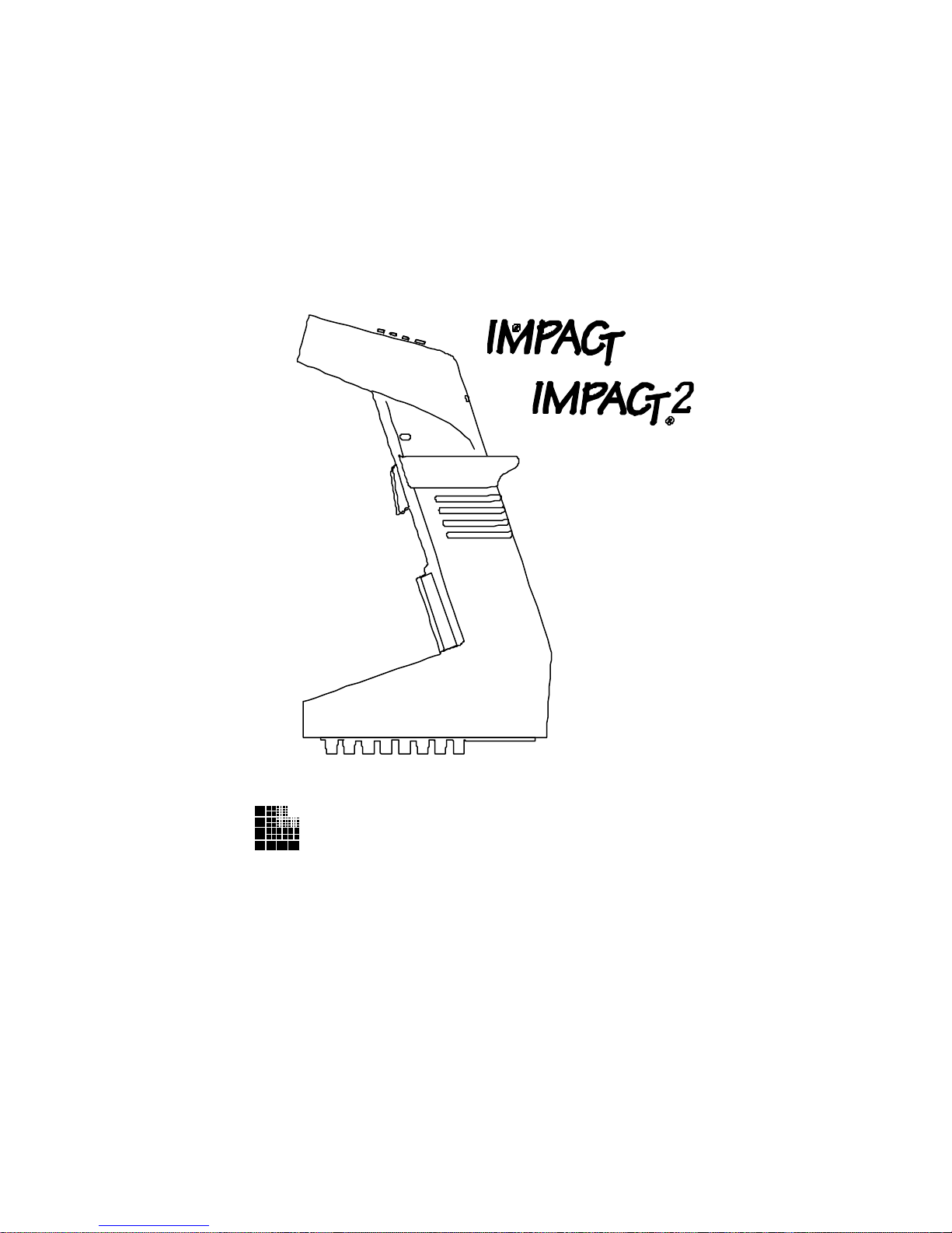
The IMPACT and IMPACT2 are available in 8-channel and
12-channel formats (see Figure A). An expandable version of the
8-channel format is also available for pipetting samples from test
tubes in a rack. It comes in several models to handle fluid volumes
from 0.5 µl to 1250 µl. The handles are color-coded for easy
identification of different model types (IMPACT vs. IMPACT2) and
different volume ranges. See Section B.4, Specifications.
8-Channel 12-Channel 8-Channel
Expandable
Figure A: IMPACT Configurations
3
Page 7
B. PIPETTOR OVERVIEW
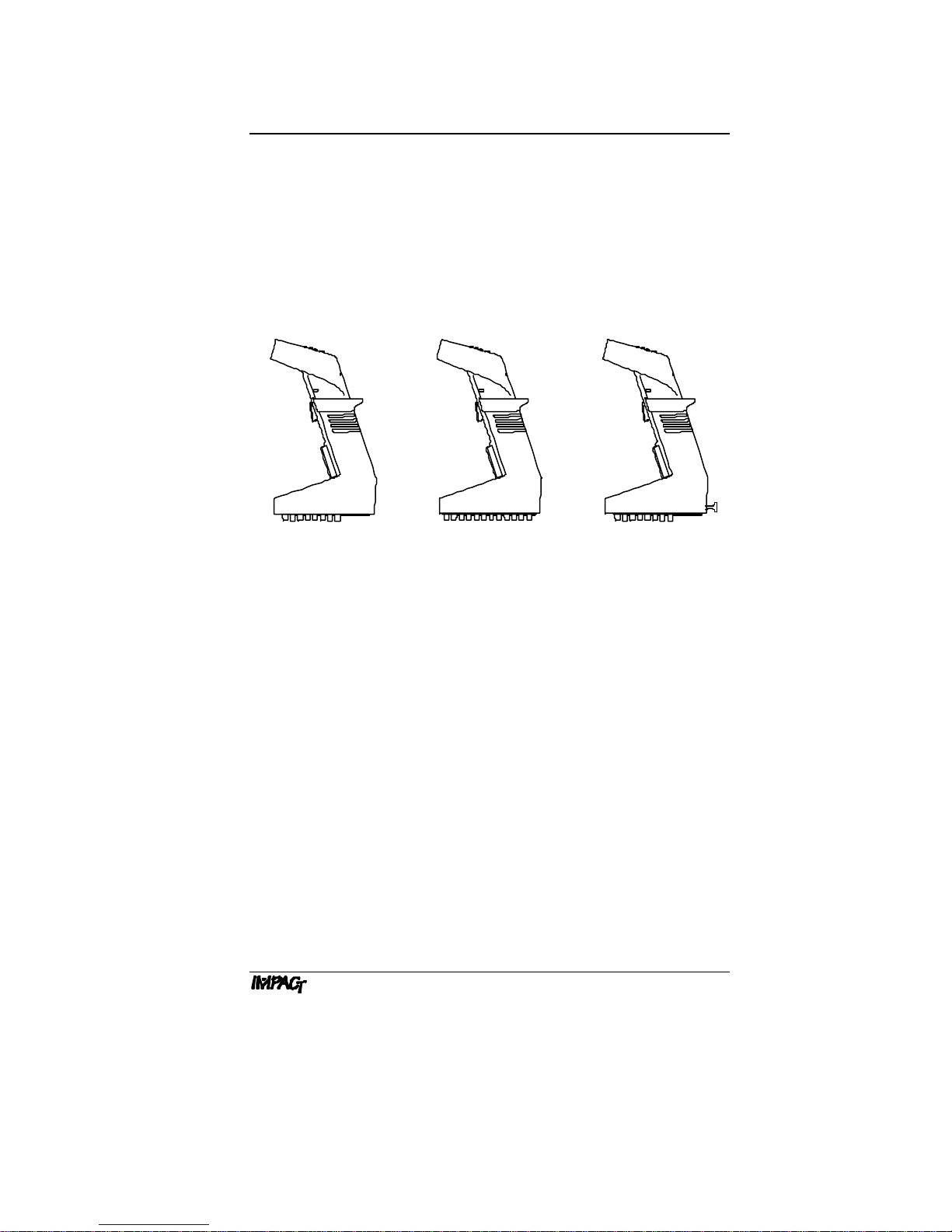
B.1 General Description
Battery
Case
Pipetting Trigger
Ejector Trigger
Tip Fittings
Figure B.1: Description of Components
Display
Keypad
Transformer
Connector
Color-coded
Ring
Keypad. The keypad contains the operation keys that are used
in programming the pipetting sequence and volumes. See Section
B.2, Keypad.
Display. The display is an LCD screen that shows the pipetting
operation (fill, dispense, mix, or purge) and fluid volume for each
step in the pipetting program. See Section B.3, Display.
4
Page 8

PIPETTOR OVERVIEW
Battery Case. The battery case contains two rechargeable nickel
cadmium batteries. Batteries are charged for 12– 14 hours. When
fully charged, the pipettor can perform up to 1200 cycles at full
stroke. Battery life is extended with automatic shutoff after 10
minutes of inactivity. See Section E.3, Installing/
Replacing Batteries.
Pipetting Trigger. The pipetting trigger initiates the pipetting
program. It is pressed when the "Run" or "Purge" command
appears in the display. A single pipetting step is performed by a
quick press and release of the trigger. Repeat pipetting (paced
dispense) is performed by pressing and holding the trigger.
Note: At the end of a paced dispense, the pipet tips should be
removed from the fluid before releasing the trigger, to prevent
aspiration of fluid.
Ejector Trigger. The ejector trigger is pressed to eject the pipet
tips from the pipettor.
Tip Fittings. The tip fittings form an airtight seal with the pipet
tips to ensure accuracy while pipetting.
Note: To extend instrument life, Matrix Technologies has
equipped all IMPACT and IMPACT2 pipettors with chemicallyresistant (PEEK) tip fittings. This material allows for pipetting of
acidic solutions without damage to the tip fittings.
Color-coded Ring. The flanged ring around the pipettor handle is
color-coded to identify the pipetting volume of the handle. See
Section B.4, Specifications.
Transformer Connector. The transformer connector receives the
plug from the power transformer for recharging the batteries. The
pipettor can be used while it is recharging.
5
Page 9
PIPETTOR OVERVIEW
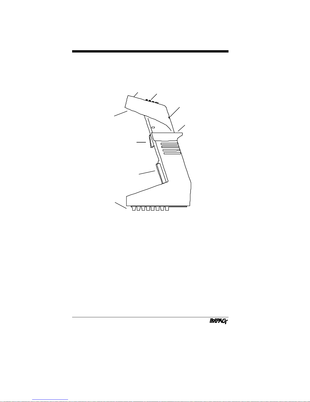
B.2 Keypad
The keypad contains the operation keys, program keys, and the
special function key.
Display
Keypad
Display
Keypad
Program
Keys
Special
Function
Fill On
Vol
Disp
Mix
Enter
Off/
Prog
Purge
Key
Figure B.2a: IMPACT Keypad
Program
Keys
Special
Function
Key
Fill On
Vol
Disp
Mix
Enter
Off/
Prog
Purge
Operation
Keys
Operation
Keys
6
Figure B.2b: IMPACT2 Keypad
Page 10

Operation Keys:
PIPETTOR OVERVIEW
[On/Off]
[Speed]
The On/Off key turns the pipettor on or off. When the
pipettor is turned on, it emits a beep tone, flashes
"ZERO" on the display, then automatically resets the
pistons to zero position. After zeroing, the display
shows the first step of the program in the RUN mode.
Note: If the pipettor is being programmed for the first
time, the first step will be the fill operation, with the
default fill volume. See Section C.1, Program-ming
the IMPACT, for the default settings.
The Speed key controls the rate at which the liquid is
aspirated or dispensed. The speed setting can be
changed by repeatedly pressing the Speed key.*
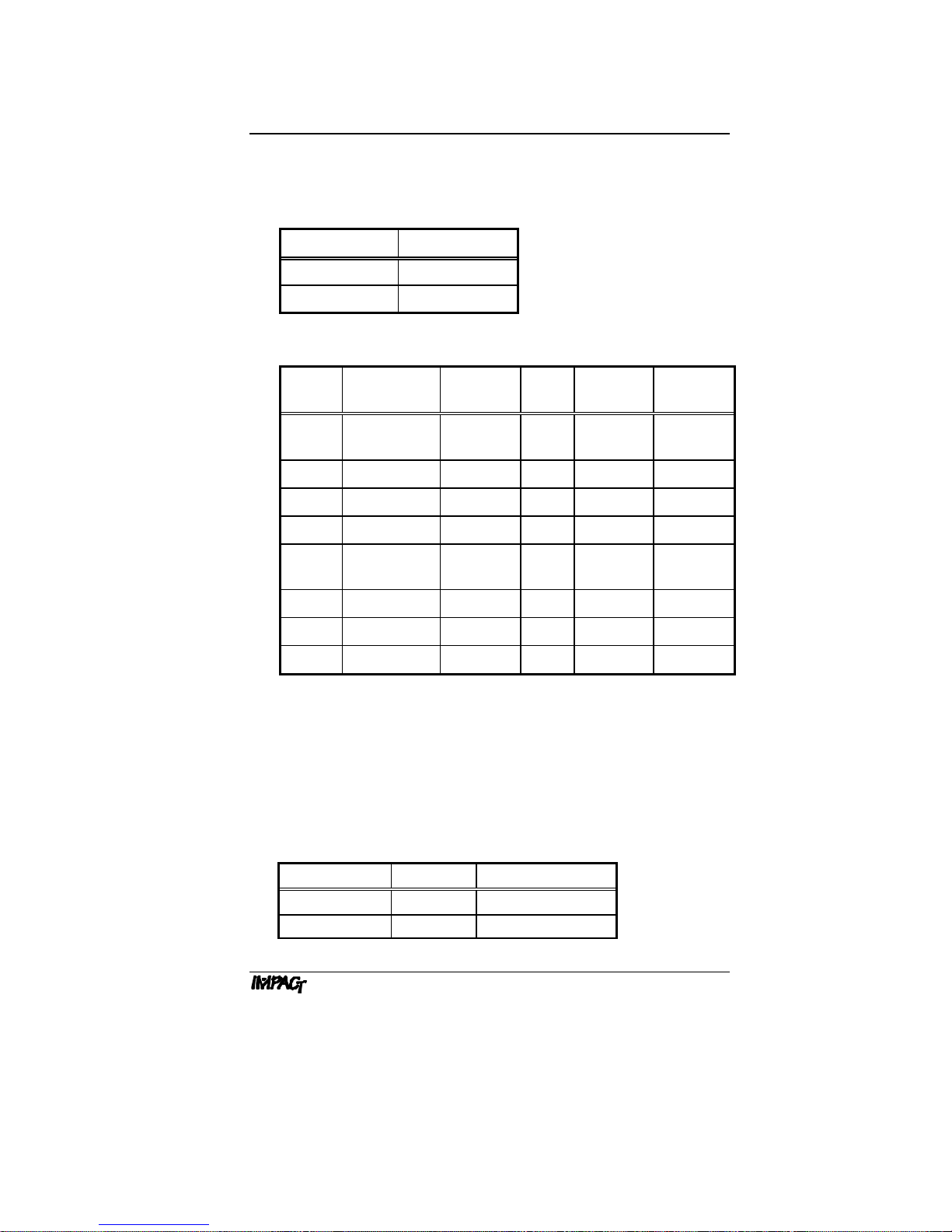
For the IMPACT, three speed settings are available:
Speed Setting Display
SLOW S F
MEDIUM S F
FAST S F
For the IMPACT2, five speed settings are available:
Speed Set ting Display
SLOW S
MEDIUM SLOW S
MEDIUM S
MEDIUM FAST S
FAST S F
The IMPACT2 also features independent speed
adjustment. Speed settings can be changed within a
stored program or during the execution of a program
(see Section C.2.4, Pipetting Speed Adjustment).
*NOTE: IMPACT2 speed settings are changed
through the Special Function key (see Special
Function key section on page 11) or by using the
volume key (see Section C.2.4, Pipetting Speed
Adjustment).
7
Page 11

PIPETTOR OVERV IEW
[Prog]
IMPACT
only
[Purge]
The current speed setting is always shown at the
bottom of the display. These settings can be selected
and changed at any time before a program step is
performed.
The Program key on the IMPACT2 enables you to
store up to five separate programs in memory for
2
future recall. Each program can hold up to 40 steps.
Programs are stored in reserved program location
numbers 1 – 5. Program “0” is used as a “scratch
pad” where temporary programs can be written, run,
and overwritten easily. Program “0” is considered to
be an “open” program (see Section C.2, Programming the IMPACT2).
The Purge key enters a purge prompt anytime during
a pipetting operation to abort the program. By
pressing the Purge key, then pressing the trigger,
you can dispense any remaining liquid from the pipet
tips and return to the beginning of the program.
The Purge key is also used to enter the purge step
into a program.
Note: If there is insufficient liquid for a final dispense
step, the pipettor emits a beep tone and automatically displays the purge prompt.
RUN The RUN mode performs the operation that is
displayed, such as fill, dispense, mix, or purge.
When "Run" appears in the display, you can activate
the RUN mode by pressing the trigger. At the end of a
pipetting sequence, the pipettor emits a triple beep
tone and returns to the beginning of the program. The
pipettor remains in RUN mode until you program a
new pipetting sequence.
8
Page 12

Program Keys:
PIPETTOR OVERVIEW
[Fill]
[Disp]
[Mix]
s
Vol
t
The Fill, Dispense, and Mix keys program the
pipetting operations. By pressing one of these keys,
you can enter the programming mode of the IMPACT.
The "Run" prompt disappears from the display and
the appropriate operation appears with a flashing
"Vol" prompt. Fill, dispense, or mix volumes can be
programmed by pressing the Volume key. Also, the
number of mix cycles can be programmed by
pressing the Mix key twice.
Automatic blowout. At the end of a final dispense
step, the pipettor automatically expels any remaining
liquid from the pipet tips with a short burst of air
(blowout). The pistons then reverse direction and
return to zero position.
Note: If you press and hold in the trigger during the
final dispense step, the pipettor performs the
automatic blowout and holds its position until you
release the trigger. This delay allows you sufficient
time to remove the tips from the liquid to prevent
aspiration of liquid, as the pistons return to zero
position.
The Volume key controls the quantity of liquid to be
aspirated or dispensed. The volume can be entered
when the "Vol" prompt appears.
IMPACT
only
Pipetting volume can be incremented quickly by
continuously depressing the Volume key. Short,
quick, depressions of the Volume key will increase or
decrease the volume by its smallest increment.
Longer depressions of the Volume key will increase
or decrease the volume in larger increments. Three
levels of volume increments are available to achieve
the desired volume (see Table C.1, Default Programming Volumes).
The Volume key can also be used to change
2
pipetting speeds within a stored program or during
the execution of a program (see Section C.2.4,
Pipetting Speed Adjustment).
9
Page 13

PIPETTOR OVERVIEW
[Enter]
The Enter key stores the program in memory. After
each step is programmed, the Enter key is pressed
once to accept the step. After the final step is
programmed, the Enter key is pressed twice to
denote the end of the program. The pipettor verifies
the end of the program with a triple beep tone.
Special Function Key:
The Special Function key is the small hole below the Volume key.
It can be activated with a pipet tip. By repeatedly pressing the
Special Function key, you can display four functions: Beep Tone
(TONE), Paced Dispense Speed (PACE), Calibration (CAL), and
Pipetting Speed—IMPACT2 only (SPd). To exit the Special
Function key at any time, press the Enter key.
TONE The beep tone signals the completion of one or more
steps, or signals a warning:
n Single beep tone: end of pipetting step; insufficient
dispense volume, purge required.
n Double beep tone: operation or program key is not
active in current mode; illegal programming step
attempted. See Section E.1, Troubleshooting.
n Triple beep tone: end of pipetting sequence;
end of programming sequence.
The single beep tone, signaling the end of a pipetting
step, can be turned ON or OFF. All other beep tones
cannot be turned off. Press the Special Function key
once to display "TONE" and its current setting. To
change the setting, press the Volume key. If the beep
tone is turned ON, the beep tone symbol " " appears
at the bottom of the display.
Note: For paced dispensing, the beep tone should
be turned on, to prepare you for each dispense step.
PACE The pace controls the speed of repeat pipetting
(paced dispensing), FAST or SLOW. Press the
Special Function key twice to display "PACE" and its
current setting. To change the setting, press the
Volume key.
10
Page 14

PIPETTOR OVERVIEW
Paced Dispense. When you use the paced
dispense feature, the pipettor dispenses the
programmed volume at the specified pace (fast or
slow). Immediately after each dispense step, the
pipettor emits a single beep tone (if beep tone is on)
to prepare you for the next dispense step. See
Section C.5, Operating Procedures.
CAL The calibration of the pipettor is factory set for
distilled water at room temperature. If you are
pipetting fluids with significantly different specific
gravities or temperatures, use this setting to
recalibrate the pipettor. See Section D, Calibration.
SPd
IMPACT
only
Once in the special function mode, adjust the
pipetting speed by pressing the Volume key. Five
2
speed settings are available:
Speed Setting Display
SLOW S
MEDIUM SLOW S
MEDIUM S
MEDIUM FAST S
FAST S F
The current speed setting is always shown at the
bottom of the display. These settings can be selected
and changed at any time before a program step is
performed.
11
Page 15
PIPETTOR OVERVIEW
Low Battery Indicator
Program No.
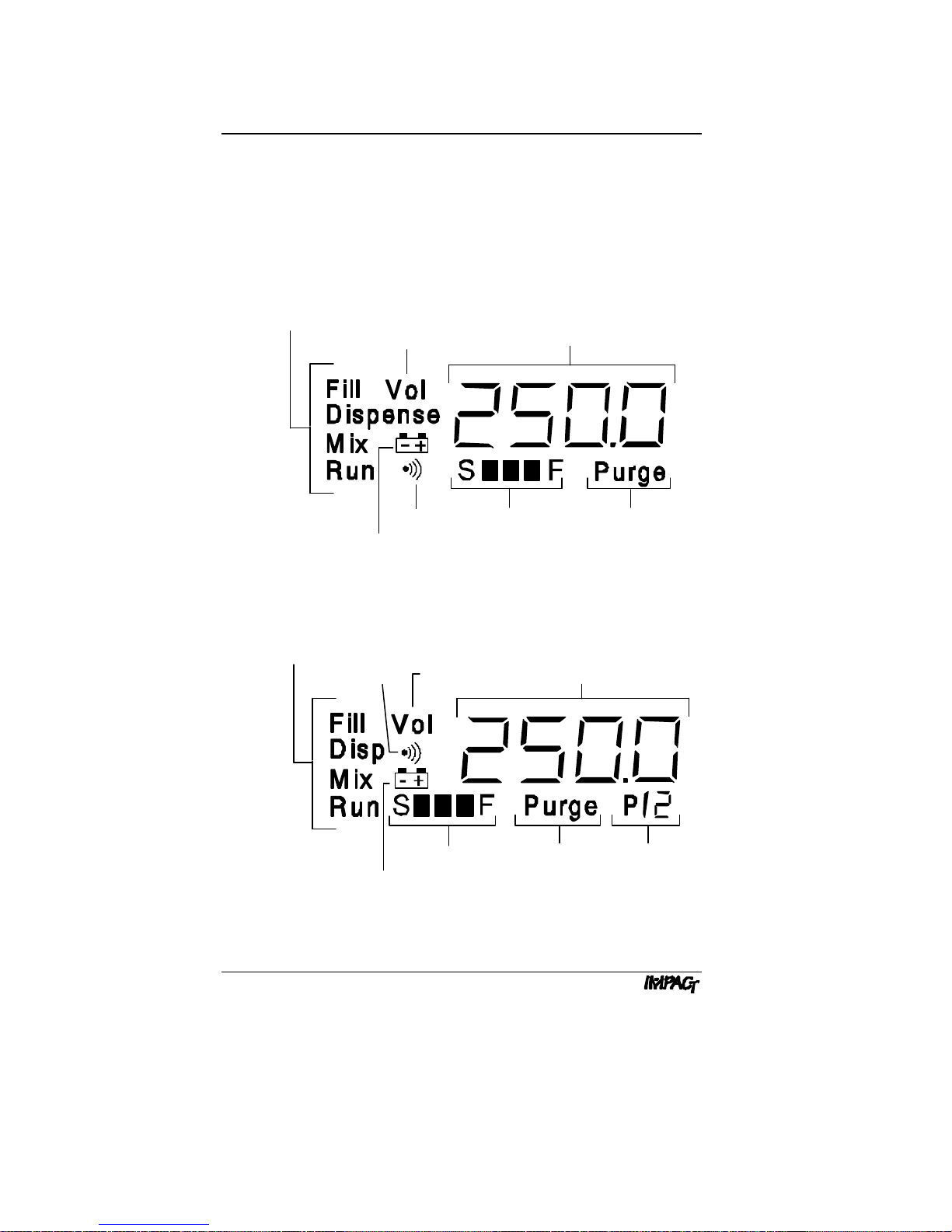
B.3 Display
The pipettor display is a dynamic LCD screen. It displays the
current operation, volume prompt (if you are entering a program),
pipetting volume, low battery indicator (appears if battery charge is
low), beep tone symbol (if the beep tone is on), pipetting speed,
and program number (IMPACT2 only).
Pipetting Operations
Volume Prompt Pipetting Volume
Beep Tone Speed Setting Purge Prompt
Low Battery Indicator
Figure B.3a: IMPACT Display
Pipetting Operations
Beep Tone
Volume Prompt
Speed Setting Purge Prompt
Pipetting Volume
Figure B.3b: IMPACT2 Display
12
Page 16
B.4 Specifications
2.5%/0.15 µl
2.5%/0.15 µl
Pipettor Type
Model Handle Color
IMPACT White
IMPACT2
Handle Specifications
PIPETTOR OVERVIEW
Gray
Handle
Size
12.50 µl 12-channel 0.50-12.50
125.0 µl 12-channel 2.0-125.0 µl Yellow 2.0%/1.0 µl 1.2%/0.8 µl
250.0 µl 12-channel 5.0-250.0 µl Blue 2.0%/1.5 µl 0.8%/1.2 µl
850 µl 12-channel 15-850 µl Orange 1.5%/4.0 µl 0.6%/2.5 µl
12.50 µl 8-channel 0.50-12.50
125.0 µl 8-channel 2.0-125.0 µl Yellow 2.0%/1.0 µl 1.0%/0.6 µl
250.0 µl 8-channel 5.0-250.0 µl Blue 2.0%/1.5 µl 0.7%/1.0 µl
1250 µl 8-channel 15-1250 µl Green 1.5%/6.0 µl 0.6%/3.0 µl
Handle Type Volume
Range
µl
µl
Color
Ring
Red
Red
Accuracy*
(±)
Precision**
(±)
2.0%/0.15
µl
2.0%/0.15
µl
Note: For Accuracy and Precision, values shown are expressed
as a percent (%) deviation or microliter (µl) value. When applied to
desired volume, the greater of the two values will always apply.
*Both values represent the deviation from the mean.
**Percentage values are expressed as the coefficient of variation.
Microliter values are expressed as the standard deviation.
Available Power Sources
Catalog No. Country Power Source
6096 England 240 V, 50 Hz
6097 Japan 100 V, 50 Hz
13
Page 17

PIPETTOR OVERVIEW
6098 USA 120 V, 60 Hz
6099 Europe 230 V, 50 Hz
14
Page 18

PIPETTOR OVERVIEW
B.5 Hazards and Precautions
There are no known hazards associated with the IMPACT when it
is operated in accordance with the instructions in this manual.
However, you should be aware of situations that can result in
serious injury.
Note: Do not perform troubleshooting procedures on the internal
components unless instructed by Matrix Technologies service
personnel.
WARNING! Ensure that the power transformer is connected to a
power receptacle that provides voltage and current specified by
Matrix Technologies. Use of an incompatible power receptacle can
cause shock and fire hazard.
CAUTION! Use only the power transformer supplied by Matrix
Technologies. Use of an incompatible power transformer can
damage the pipettor.
CAUTION! Always turn off the power and unplug the power
transformer before cleaning the exterior. Fluid seepage can
damage internal components.
CAUTION! Do not immerse the unit in liquid. Fluid seepage can
damage internal components.
CAUTION! Do not autoclave the entire unit. Extreme heat can
damage the display and other electronic components.
Note: For autoclaving specific portions of the pipettor, refer to the
Autoclaving Procedures, or call Matrix Technologies, Technical
Service Department, for instructions.
CAUTION! Do not clean the keypad with bleach solution or other
solvents. Caustic cleaning solutions can damage the keypad.
CAUTION! Avoid excessive charging of the batteries when the
pipettor is not in use. Excessive charge to the batteries will
shorten the battery life and may damage the batteries.
15
Page 19

C. PROGRAMMING AND OPERATION
Programming the IMPACT and IMPACT2 is fast and easy. Pipetting
steps and volume are entered in the sequence that they will be
performed, then the program is saved to memory. This program
will stay in memory (even if the pipettor is turned off, or the battery
runs low) until you change it. Up to 40 programming steps can be
entered and stored in the IMPACT pipettor. Five programs, each
capable of holding 40 steps, can be entered and stored in the
IMPACT
C.1 Programming the IMPACT
To enter a pipetting program:
1. Turn on pipettor. Press the green [On/Off] key to turn on
2
.
the pipettor. The pipettor will beep once and flash "ZERO" on
the display while resetting the pistons to zero position. The
first step of the current program is displayed.
Note: If the pipettor is being programmed for the first time,
the first step will be the fill operation, with the default fill
volume displayed (see the following table).
Handle
Volume
12.50 10.00 10.00 5.00 0.05 0.10 0.50
125.0 100.0 100.0 50.0 0.1 0.5 5.0
250.0 250.0 50.0 50.0 0.5 5.0 25.0
850 850 100 100 1 5 50
1250 1250 100 100 1 5 50
Fill
Volume
Dispense
Volume
Mix
Volume
Volume Increment
(slow –> fast)
Table C.1: Default Programming Volumes*
*All volumes shown are in microliters (µl).
15
Page 20

PROGRAMMING AND OPERATION
2. Select pipetting operation. Enter the programming mode
by pressing the [Fill] or [Mix] key.
For example, to begin programming with a filling operation,
press the [Fill] key. The display shows "Fill" with a flashing
"Vol" prompt:
Flashing Display
Note: The displayed volume defaults to the last volume
programmed for the selected operation, or to the default
volume for the pipettor, if it is being programmed for the first
time.
Fill. The [Fill] key programs the pipettor to aspirate a volume
of liquid. A single fill step can be programmed for fluid
transfers, or a combination of fill steps can be programmed for
dilutions or supernatant collection.
Dispense. The [Disp] key programs the pipettor to dispense
a volume of liquid. The dispense volume can be the entire fill
volume, or a smaller increment for repeat pipetting. You only
have to program the dispense volume once for repeat
pipetting. The pipettor will dispense the volume each time the
trigger is pressed (or repeatedly during a paced dispense) until
the fill volume is reached, or until insufficient volume remains.
Mix. The [Mix] key programs the pipettor to perform a
combination of fills and dispenses. You can program a mix
volume or mix cycle (single fill and dispense). You can press
[Mix] once to program a mix volume, or twice to program a
mix cycle. Mix cycles from 1 to 9 are available on the
IMPACT; mix cycles from 2 to 9 are available on the IMPACT
The default setting is three mix cycles.
16
2.
Page 21

PROGRAMMING AND OPERATION
Listed below are some programming considerations for the
mix operation:
n If the program begins a mix cycle from zero position, it will
complete the cycle with an automatic blowout, then
display "ZERO." Press the trigger to return the pistons to
zero position.
n If the program begins a mix cycle above zero position
(volume is greater than zero), the fluid is dispensed, and
the mix cycle begins. The mix cycle will end at the same
volume it started with. Also, the mix operation will remain
in the display so it can be repeated (useful for serial
dilutions). To end the mix operation, press the [Purge]
key, then press the trigger.
Purge. The [Purge] key programs the pipettor to purge the
fluid. This step can be entered as a program step, or it can be
pressed anytime while pipetting to terminate the program and
dispense the remaining liquid.
Note: If the program ends at a volume greater than zero, and
the last step is not a mix cycle, the "Purge" prompt
automatically appears. Also, the pipettor emits a beep tone to
warn you that some fluid remains. Press the trigger to
dispense the remaining fluid and return to the beginning of the
program.
Examples of pipetting programs with different mix steps are
shown in Section C.4, Programming Examples.
3. Enter volume. Enter the desired volume for [Fill], [Disp], or
[Mix] by pressing the up s or down t side of the [Vol] key. If
the [Vol] key is pressed and released quickly, the volume
changes by its smallest increment of measure (for example,
0.5 µl for the 250 µl pipettor); if the [Vol] key is pressed and
held, then the volume change occurs with larger increments
(see Table C.1, Default Programming Volumes, for volume
increment).
Note: The [Purge] key does not use a volume; therefore, if
you have entered a purge step, continue to the next step.
17
Page 22

PROGRAMMING AND OPERATION
Flashing
Display
4. Confirm programming step. Press [Enter] to confirm the
programming step. The display flashes all of the operation
keys to prompt you for the next programming step:
{
5. Select next pipetting operation. Repeat steps 2 to 4 until
all programming steps have been entered.
6. Save program and exit. When the display flashes all
operation keys, press [Enter] to save the program and exit
the programming mode. The pipettor emits a triple beep tone
to signal the end of the programming sequence. The first step
in the program is displayed. "Run" is displayed in the lower
left corner to indicate that the new program is ready to be run.
Go to Section C.3 for Reviewing the Program, or Sec tion C.5
for Operating Procedures.
18
Page 23

PROGRAMMING AND OPERATION
C.2 Programming the IMPACT2
C.2.1 Program Selection
To create and store programs in the IMPACT2:
1. Select the program number by pressing the [Prog] key,
then press the [Vol] key until the desired program number
is displayed.
2. Press and hold the [Prog] key, while simultaneously
pressing the Special Function key to enter the programming mode. The prompt “Prog” will appear on the display.
3. Begin entering your new program (see Section C.1,
Programming the IMPACT, for programming instructions).
NOTE: When programming mode is active, the Speed
setting and Beep Tone symbols will blink.
After you have pressed the [Enter] key to save and exit the
program, your new program will be stored under the
selected program number. The program number will be
displayed for two seconds. (The first step of the newly
written program is displayed).
This program is ready to be run.
C.2.2 Program Recall
To recall a stored program:
1. Press the [Prog] key, then the [Vol] key to select the
desired program number.
2. Press the [Enter] key to activate the displayed program.
19
Page 24

PROGRAMMING AND OPERATION
C.2.3 Scratch Pad Mode (Program 0)
While providing ample program storage, the IMPACT2 also
offers a “scratch pad” or open programming mode. This mode
is identified by “P/0,” which appears in the program section of
the display (refer to the IMPACT2 display on page 12). This
feature enables you to quickly change pipetting protocols
without affecting previously stored programs.
To use the “scratch pad” mode: From the start of any
program, simply begin entering a new protocol (selecting a
pipetting operation as described on page 16). This new
protocol can now be used, and will remain active until a stored
program is retrieved. “P/0” appears in the program ID section
of the display to indicate that the (O)pen programming mode,
or “scratch pad” mode, is active.
C.2.4 Pipetting Speed Adjustment
The IMPACT2 offers unique speed control that is function
based, enabling speeds for Fill, Dispense, Mix or Purge to be
independently programmed. Also, speeds within any of the five
stored programs can be independently set and stored as an
integral part of the pipetting protocol. Pipetting speed is easily
changed at the start of each pipetting function.
20
To change pipetting speed during the execution of a program:
Press the [Vol] key to select the speed for each pipetting
function (Fill, Dispense, Mix, or Purge).
This newly set speed will remain active with each function
even if the pipettor is turned off. Speed settings within any of
the five stored programs will also remain in memory with the
program functions until changed by the operator.
Page 25

C.3 Reviewing the Program
After you have programmed your pipettor, you may want to review
the programming steps:
1. Set pipettor for RUN mode. Ensure that the pipettor is in
the RUN mode ("Run" appears in the lower left corner of the
display). If the display is flashing all pipetting operations, you
are still in the programming mode; press [Enter] to save the
program and exit.
2. Begin program. Run the program without using pipet tips or
aspirating fluid. Press the trigger for each step in the program.
3. Observe display. At each step of the program, observe the
display. If necessary, re-enter the programming sequence.
Listed below are a few helpful hints for reviewing your program:
n If your program is complex and contains several steps,
you may want to write the steps on paper before entering
the program steps (or use a copy of the programming
worksheet at the end of this manual). Check off each step
as you review the program.
n If your program is intended for paced dispensing, review
the program again, with the trigger depressed until the last
step. Check the dispense pace to ensure that you can
keep up with the dispense steps.
PROGRAMMING AND OPERATION
21
Page 26

PROGRAMMING AND OPERATION
OR
[Enter] [Enter]
C.4 Programming Examples
Examples of different pipetting sequences are described below.
These examples are ideal for use as training exercises. Press the
keys shown in keycaps [ ], then press the [Vol] key until the
volume in parent heses ( ) is displayed. At the end of the program,
a triple beep tone is sounded. See Section F, Appendices, for
additional pipetting examples.
C.4.1 Sample Transfers
Example: Fill and dispense 100 µl.
Option 1 Option 2
[Fill]
s
Vol
(100) [Enter]
t
[Fill]
Vol
s
t
(100)
[Disp]
s
Vol
(100) [Enter] [Enter]
t
The second option is a one-step program. Because the program
ends at a volume greater than zero, and the last step is not a mix,
a "Purge" prompt automatically appears at the end of the fill to
dispense the liquid and return to the beginning of the program.
C.4.2 Incremental Pipetting
Example: Fill 250 µl and dispense 45 µl in 5 increments.
s
Vol
[Fill]
[Disp]
In this program, only one dispense step needs to be programmed.
If any program ends in a dispense step, the pipettor repeats the
dispense step until the volume is zero, or is less than the
programmed dispense volume. If the remaining volume is less than
the programmed dispense volume, the pipettor displays a "Purge"
prompt to discard the remainder.
22
(250) [Enter]
t
s
Vol
(45) [Enter] [Enter]
t
Page 27

PROGRAMMING AND OPERATION
C.4.3 Serial Dilutions
Example: Transfer 100 µl to the first column of a plate previously
filled with reagent. Mix 200 µl for 2 cycles. Transfer 100 µl to the
second column and repeat the mix step. Follow this procedure for
the rest of the plate.
s
Vol
[Fill]
[Mix]
(100) [Enter]
t
s
Vol
(200) [Mix]
t
s
Vol
(2) [Enter] [Enter]
t
That's the entire program! The mix step always returns to the
volume at which it started (100 µl); therefore, the pipettor
continues the mix step indefinitely, until you press the [Purge]
key to end the program. In this example, the mix cycle is
programmed for 2 cycles (default is 3 cycles).
C.4.4 Simple Dilutions
Example: Prepare 1:10 dilution with a 10 µl sample volume.
s
Vol
[Fill]
[Fill]
[Fill]
(90) [Enter]
t
s
Vol
(20) [Enter]
t
s
Vol
(10) [Enter]
t
[Purge] [Enter] [Enter]
The first fill volume is for the diluent (90 µl), followed by an air-gap
(20 µl), and finally by the sample volume (10 µl). The purge step
will dispense the total volume.
23
Page 28

PROGRAMMING AND OPERATION
C.4.5 Supernatant Collection
Example: Aspirate 100 µl from 8 rows of a microtiter plate and
discard the total volume.
s
Vol
[Fill]
[Fill] [Enter]
[Fill] [Enter]
[Fill] [Enter]
[Fill] [Enter]
[Fill] [Enter]
[Fill] [Enter]
[Fill] [Enter]
[Purge] [Enter] [Enter]
This program is performed with the 850 µl handle. All 100 µl fill
volumes are collected in the same tips. When completed, the total
volume is discarded with the purge step.
(100) [Enter]
t
24
Page 29

PROGRAMMING AND OPERATION
C.5 Operating Procedures
After you have programmed your pipettor, you are ready to begin
pipetting. The display should show the first program step, with the
"Run" prompt showing in the lower left corner:
The following steps describe a basic program for pipetting reagent
into a microtiter plate. The pipettor is programmed as follows:
[Fill]
[Disp]
s
Vol
(250) [Enter]
t
s
Vol
(30) [Enter] [Enter]
t
1. Attach pipet tips. When you are ready to begin pipetting,
attach the pipet tips to the pipettor.
2. Aspirate liquid. Immerse the pipet tips into the liquid to be
aspirated, then press the trigger to aspirate 250 µl.
3. Dispense liquid. Position the pipet tips over the first column
of wells in the microtiter plate, and press the trigger to
dispense 30 µl. At the completion of the dispense step, the
pipettor emits a single beep tone (if the beep tone is on).
4. Repeat dispense step. Repeat the previous step for the rest
of the columns in the microtiter plate. At the completion of the
eighth dispense, the pipettor emits a double beep tone (if the
beep tone is on, otherwise it emits a single beep tone) and
displays the "Purge" prompt. There is insufficient volume for
another 30 µl dispense, and the pipettor signals for a purge
step.
5. Discard remaining liquid. Position the pipet tips over a
waste container and press the trigger to purge the remaining
liquid. The pipettor emits a triple beep tone to signal the end of
the program, then returns to the first step of the program.
6. Eject tips. Press the ejector trigger to eject the used pipet
tips.
25
Page 30

PROGRAMMING AND OPERATION
Paced Dispense. Step 4 can also be performed as a paced
dispense. Instead of pressing the trigger for each dispense step,
press and hold the trigger to automatically dispense each volume.
Immediately after each dispense step, the pipettor emits a single
beep tone (if the beep tone is on), prompting you to prepare for the
next dispense step. To stop a paced dispense, release the trigger
before the end of the last dispense step.
Note: For paced dispensing of small volumes, set the pace to
SLOW. Ensure that you have fully released the trigger before the
end of the last dispense step to prevent an additional, unwanted
dispense step.
26
Page 31

D. CALIBRATION
The IMPACT and IMPACT2 are factory -calibrated for distilled water
at 20°C. For easy calibration, using distilled water, the IMPACT
2
pipettor features an “EASY ” CAL mode (see Section D.2,
Calibrating the IMPACT2 ). When pipetting liquids of significantly
different specific gravities or temperatures, however, the Calibration
(CALC) feature may be used for both the IMPACT and IMPACT
2
pipettors to achieve greater accuracy (see Section D.1, Calibrating
the IMPACT).
To prepare for calibration, ensure that the pipettor and tips are at
room temperature. When calibrating the pipettor, select only one
channel to pipet with. Using an analytical balance, first obtain the
actual value of the programmed volume at factory calibration. The
programmed volume (Vp) used is typically the full volume of the
pipettor (for example, 250 µl for the 250 µl 8-channel pipettor), but
is not limited to this volume.
27
Page 32

CALIBRATION
D.1 Calibrating the IMPACT
D.1.1 Volume Measurement
To measure the actual value of the programmed volume:
1. Fill the programmed volume (Vp), then dispense the entire
volume into a container on the analytical balance.
2. Read the weight on the analytical balance. Repeat this
procedure ten times.
Note: Use a clean and dry pipet tip with each pipetting cycle.
When filling the liquid, immerse the pipet tip approximately
¼ inch (approx. 0.6 cm) below the liquid surface. When
dispensing the liquid, touch the side of the container to ensure
a complete dispense.
3. Determine the average weight of the programmed volume and
convert it to volume. To convert to volume, correct the weight
for specific gravity and temperature.
If you are weighing water, use one of the correction factors
below:
Temperature Correction Factor
20°C - 22.5°C 1.003
23°C - 25°C 1.004
The resulting volume is the corrected actual volume. If the
pipettor is correctly calibrated, the programmed volume should
equal the actual volume (within the specifications of the
pipettor).
28
Page 33

D.1.2 Pipettor Calibration
To calibrate the pipettor:
CALIBRATION
1. Calculate display volume of the pipettor: Dv =
V
p x C
p
V
a
Vp = Programmed Volume
Va = Corrected Actual Volume (corrected for temperature)
Cp = Calibration Point (each pipettor handle has its own
calibration point, see the table below)
Dv = Display Volume
Handle
Size
12.50 µl 10.00 268
125.0 µl 100.0 483
250.0 µl 200.0 375
850 µl 700 882
1250 µl
Calibration
Point (µl)
1000 845
Calibration
Factory
Steps
Table D.1.2: Calibration Specifications
2. Enter the CALC mode on the pipettor by pressing the Special
Function key (use a pipet tip to press the key) until the
“CALC” function flashes on the display, followed by the
calibration point.
3. Press the [Vol] key to enter the Display Volume (Dv)
calculated above .
4. Press the [Enter] key to set the calibration point . The display
shows “CAL” then “SET” to confirm the new calibration point,
and returns to the current pipetting program.
29
Page 34

CALIBRATION
Example: Calibrate a 1250 µl 8-channel pipettor.
Water temperature = 24°C
Programmed Volume (Vp) = 1000 µl
Average of Actual Volume = 990 µl
Corrected Actual Volume (Va) = 990 x 1.004 = 994 µl
Calibration Point (Cp) = 1000
Vp
Dv =
Dv =
x C
V
a
1000 µl
994 µl
p
x 1000
Dv = 1006
30
Page 35

D.2 Calibrating the IMPACT2
CALIBRATION
IMPACT
using the “EASY ” CAL mode or with other liquids using the original
“CAL” mode (displayed as “CALC” on the IMPACT2).
2
users can calibrate their pipettors with distilled water
D.2.1 “EASY” CAL Mode
IMPACT
unique “EASY ” CAL feature. “EASY” CAL has been developed for
fast, easy, in-lab verification and/or calibration using distilled wat er
at room temperature (20-22.5°C).
1. Weigh out ten aliquots of distilled water on an analytical
Note: Ensure that the distilled water used is at room
2. Calculate an average for the ten readings of distilled water
2
users can quickly calibrate their pipettor by using the
balance, using one pipetting channel. The programmed
dispense volume must correspond to the calibration point for
that pipettor (for example, 200 µl for a 250 µl pipettor). Refer to
Table D.1.2, Calibration Specifications, for proper calibration
points.
temperature (20-22.5 °C). An internal correction factor of
1.003 is used by the pipettor to convert weight (gm) to volume
(µl).
obtained from the balance. If the resulting average weight is
within your accuracy specifications, no further calibration is
required. If the average weight does not meet expected
performance, enter the “EASY ” CAL mode to quickly re-
calibrate the IMPACT2.
3. Enter the “EASY” CAL mode by pressing the Special Function
key (using a pipet tip) until “EASY ” flashes, then press the
[Enter] key to display the calibration point.
4. Use the [Vol] key to adjust the displayed calibration point
until it matches the average weight obtained in step 2. Store
this number by pressing the [Enter] key . The new calibration
setting is confirmed by the “CAL” and “SET” messages on the
display.
31
Page 36

CALIBRATION
5. Verify this new calibration setting by repeating Steps 1 and 2.
D.2.2 “CALC” Mode
To calibrate the IMPACT2 pipettor for liquids other than water, use
the original CAL mode (displayed as “CALC” on the IMPACT2):
1. Measure the programmed volume (see Section D.1.1, Volume
Measurement).
2. Calculate the display volume of the pipettor (see step 1 in
Section D.1.2., Pipettor Calibration).
3. Enter the CAL mode on the pipettor by pressing the Special
Function key (using a pipet tip) until “EASY” appears on the
display.
4. Press the [Vol] key to display “CALC” (pressing the [Vol]
key again will return you to the “EASY ” mode).
5. Press the [Enter] key to display the calibration point.
6. Press the [Vol] key to enter the Display Volume (Dv)
calculated in Section D.1.2., Pipettor Calibration.
7. Press the [Enter] key to set the calibration point . The display
shows “CAL” then “SET” to confirm the new calibration point,
and returns to the current pipetting program.
D.3 CALVIEW
CALVIEW displays the pipetting stroke (number of steps) used to
reach the calibration point. This value allows you to confirm the
calibration during pipetting. To activate CALVIEW, enter the CAL
mode using the Special Function key . When the calibration point
is displayed, press the [Fill] key. The number of steps is
displayed. Press any key to exit CALVIEW.
D.4 CALRESET
CALRESET allows you to return to the factory calibration. To reset
the calibration, enter the CAL mode using the Special Function
key. When the calibration point is displayed, press the [Purge]
key. The display flashes “FACT,” “CAL,” then “SET” and the pipettor
32
Page 37

CALIBRATION
resets to factory setting (see Table D.1.2, Calibration
Specifications, for the factory calibration steps).
D.5 Recommendations for Accurate Pipetting
IMPACT and IMPACT
2
pipettors are factory calibrated to deliver
accurate volumes with distilled water at 20°C. By using the
calibration procedures described in Sections D.1, Calibrating the
IMPACT, and D.2, Calibrating the IMPACT
2
, you can pipet liquids
of different specific gravity with a high degree of accuracy and
reproducibility. For optimal pipetting results, refer to the following
recommendations:
n When using factory calibration, the liquid to be pipetted should
not contain specific gravity and vapor pressure that is
significantly different from distilled water.
n When pipetting liquids with low vapor pressure and/or high
surface tension, pre-wet the pipet tips with the liquid to reduce
possible loss of accuracy.
n Before aspirating any liquid, fully immerse pipet tips into the
liquid to prevent aspiration of air. Tips should be immersed
approximately ¼ inch (approx. 0.6 cm) below the liquid.
n When accurate dispensing of several increments of liquid are
needed, discard the last increment. The cumulative percentage of error from previous increments exists on the last
volume.
n Pipet viscous liquids at the slowest speed to ensure accurate
pipetting.
n During the dispensing of a liquid, touch the tip against the side
of the receiving container to prevent any liquid from remaining
on the tip.
n If you cannot touch the tip against the receiving container,
dispense the liquid at the fastest speed for crisp liquid
delivery.
33
Page 38

E. TROUBLESHOOTING AND MAINTENANCE
E.1 Troubleshooting
Listed below are possible procedural and system problems, as
well as recommended solutions. If you cannot resolve the problem,
call Matrix Technologies, Technical Service Depart -ment.
No power to the pipettor. Batteries are incorrectly installed.
n Recheck the orientation of the batteries, they should match
the diagram in the battery case.
Double beep tone occurs. An illegal programming step is
being entered, such as programming two fills that exceed the
maximum fill volume.
n Recheck your programming sequence. Ensure that you are
not attempting to fill above the maximum fill volume of the
pipettor, or attempting to dispense more than the total fill
volume.
“ERR_1” is displayed. This error message signifies one of the
following conditions:
n The pipettor cannot complete an automatic blowout. The
batteries are significantly drained of power, causing the motor
to stall.
Recharge the batteries immediately.
n The motor is defective or the flex circuit assembly is
damaged.
Contact Matrix Technologies, Technical Service Department.
The motor sounds rough and aspiration is very slow.
n The IMPACT
Verify the speed setting, the slowest speed setting normally
2
has been set to the slowest speed.
causes the motor to run very slowly and louder than usual.
34
Page 39

TROUBLESHOOTING AND MAINTENANCE
E.2 Cleaning
The IMPACT requires very little maintenance. The exterior of the
pipettor can be cleaned periodically with a soft cloth moistened
with methyl alcohol.
CAUTION! DO NOT AUTOCLAVE entire unit or clean the keypad
with bleach solution or other solvents. Extreme heat can damage
the display and other electronic components. Caustic cleaning
solutions can damage the keypad.
Note: For autoclaving specific portions of the pipettor refer to the
Autoclaving Procedures, or call Matrix Technologies, Technical
Service Department, for instructions.
Note: Avoid prolonged exposure to ultraviolet light. The handle
housing may become discolored or damaged.
35
Page 40

TROUBLESHOOTING AND MAINTENANCE
E.3 Installing/Replacing Batteries
Your IMPACT pipettor is shipped with batteries packaged
separately. Before using the pipettor, install the batteries and
recharge them for 12 – 14 hours. Use the following procedure to
install the batteries, then continue to Section E.4, Recharging
Batteries.
Under normal use, the batteries can be recharged approximately
400 times. When they can no longer hold their charge, the
batteries must be replaced. Replacement batteries can be
purchased through Matrix Technologies .
The following procedure describes installation, or replacement, of
the batteries:
Note: If you are replacing batteries, ensure that the pipettor is
turned off before removing the battery case.
1. Remove battery case. Position your thumb over the thumb
grips (see Figure E.3a) and brace your fingers against the front
of the keypad. Apply firm pressure to the panel with the thumb
grips to release the latch. Carefully slide the battery case out of
the pipettor, allowing sufficient slack for the attached wires.
Thumb Grips
Bottom of Keypad
Figure E.3a: Removing Battery Case
36
Page 41

TROUBLESHOOTING AND MAINTENANCE
Battery Case
(bottom)
Pipet Tip
Batteries (behind slot)
Battery Case
(top)
Nickel Cadmium Batteries
2. Remove batteries. Press a pipet tip against either battery
through the slot in the bottom of the battery case to remove the
batteries.
Figure E.3b: Removing Batteries
3. Install new batteries. Insert new batteries by placing the
positive end into the battery case first, then the negative end.
Ensure that the batteries are in the correct orientation (see
Figure E.3c, or diagram in the battery case).
+
+
Figure E.3c: Installing Batteries
4. Return battery case to pipettor. Carefully insert the battery
case into the pipettor. The case will click when the latch is
securely attached to the handle.
Note: If the case does not close easily, ensure that the wires
are not obstructing the opening.
5. Recharge batteries. Recharge the new batteries before using
the pipettor (see Section E.4, Recharging Batteries).
37
Page 42

TROUBLESHOOTING AND MAINTENANCE
E.4 Recharging Batteries
The IMPACT and IMPACT2 use two nickel cadmium rechargeable
batteries, located in a battery case under the keypad. The
batteries are charged while they are in the pipettor by using the
power transformer included in the package. You can operate the
pipettor while it is recharging; or you can operate it solely with the
power transformer (without batteries). When fully charged, the
pipettor will perform over 1200 cycles at full stroke. The batteries
can be recharged approximately 400 times. To extend battery life,
the pipettor will turn off automatically if it is not used within ten
minutes.
Note: Spare batteries and external battery chargers can be
ordered through Matrix Technologies.
Battery charge is low when the battery symbol
– +
Use the following steps to recharge the batteries:
1. Attach transformer. Attach the cable end of the transformer
into the pipettor. The plug receptacle is above the color ring.
Plug the transformer into the electrical outlet.
appears on the display . The pipettor will continue to
function, but should be recharged at the earliest
convenient time.
2. Recharge batteries. Recharge the batteries for 12-14 hours
to ensure a full charge. After the batteries have been recharged,
unplug the pipettor from the transformer. The pipettor is now
ready for use.
Note: Batteries hold their maximum charge if they are fully
discharged before recharging again. However, overnight
recharging is acceptable if the pipettor is in normal use during
the day.
CAUTION! Avoid excessive charging of the batteries when the
pipettor is not in use. Excessive charge to the batteries will
shorten the battery life and may damage the batteries.
38
Page 43

F. APPENDICES
F.1 Additional Pipetting Examples
F.1.1 Sample Transfers
Example #1: Transfer 100 µl and mix 200 µl for 2 cycles
immediately after transfer.
s
Vol
[Fill]
[Purge] [Enter]
[Mix]
When a purge is programmed before a mix cycle, the pipet tips
are emptied and mixing occurs automatically without pressing the
trigger. At the end of the mix, "ZERO" flashes in the display.
Remove the pipet tips from the liquid and press the trigger to
return the pistons to zero position.
Example #2: Mix 250 µl for 3 cycles, then transfer 150 µl.
[Mix]
[Fill]
[Disp]
(100) [Enter]
t
s
Vol
(200) [Mix]
t
s
Vol
(2) [Enter] [Enter] [Enter]
t
Option 1 Option 2
s
Vol
(250) [Enter] [Fill]
t
s
Vol
(150) [Enter] OR [Mix]
t
s
Vol
(150) [Enter] [Enter]
t
[Purge] [Enter] [Enter]
s
Vol
(150) [Enter]
t
s
Vol
(250) [Enter]
t
Option 1 requires an additional trigger press at the end of the mix
to zero the pistons (remove tips from liquid before zeroing).
Note: The mix cycle default is 3 cycles and does not need to be
programmed — unless it was changed in a previous program.
Option 2 minimizes the number of trigger presses and executes a
dispense by using the [Purge] key. First, fill the assigned volume
of liquid, then leave the tips in the liquid and execute the mix step.
Finally, transfer 150 µl by using the purge step.
Note: The mix step always returns to its starting volume;
therefore, the volume will be 150 µl at the end of the mix step.
39
Page 44

APPENDICES
F.1.2 Incremental Pipetting
Example: Fill 250 µl and dispense 45 µl in the first column of the
microtiter plate. Reduce each subsequent column by 5 µl for a
total of 8 columns. Discard the remainder.
[Fill]
[Disp]
[Disp]
[Disp]
[Disp]
s
Vol
(250) [Enter]
t
s
Vol
(45) [Enter]
t
s
Vol
(40) [Enter]
t
s
Vol
(35) [Enter]
t
s
Vol
(30) [Enter]
t
[Disp]
[Disp]
[Disp]
[Disp]
[Purge] [Enter] [Enter]
s
Vol
(25) [Enter]
t
s
Vol
(20) [Enter]
t
s
Vol
(15) [Enter]
t
s
Vol
(10) [Enter]
t
A purge step is entered as the last step in the program to limit the
dispense step to eight columns; otherwise, the pipettor would
dispense 10 µl until it was empty.
F.1.3 Serial Dilutions
Example: Transfer 50 µl to the first column of a plate, mix 100 µl.
Follow this procedure for exactly 4 columns.
s
Vol
[Fill]
[Mix]
(50) [Enter]
t
s
Vol
(100) [Enter]
t
[Mix] [Enter]
[Mix] [Enter]
[Mix] [Enter]
[Purge] [Enter] [Enter]
This program requires a specified number of steps; therefore, each
mix step is entered, and the program is ended with a purge step.
Since the subsequent mix steps use the same volume, the volume
does not need to be entered each time.
40
Page 45

APPENDICES
F.1.4 Simple Dilutions
Example: Prepare a 1:21 dilution with a 10 µl sample volume.
Dispense the total volume into a column and mix immediately.
s
Vol
[Fill]
[Fill]
[Fill]
[Purge] [Enter]
[Mix]
This program contains an air-gap (20 ul) and mix step at the end.
The mix step begins immediately after the purge, without pressing
the trigger. Then the pipettor empties the pipet tips and displays
"ZERO." Remove the tip from the liquid, and press the trigger to
return the pistons to zero position.
Note: Whenever a purge step is immediately followed by a mix
step, mixing will occur automatically, without pressing the trigger.
(200) [Enter]
t
s
Vol
(20) [Enter]
t
s
Vol
(10) [Enter]
t
s
Vol
(150) [Enter] [Enter ]
t
F.2 Chemical Compatibility
With the IMPACT family of pipettors, operators can confidently
pipet acidic solutions or stopping agents without damaging the
pipet tip fittings. All pipettors are equipped with chemicallyresistant tip fittings which can withstand the corroding effects of
any acidic solution. Also, the IMPACT tip fittings can be wiped with
a bleach solution (5% sodium hypochlorite) for decontamination.
41
Page 46

APPENDICES
F.3 Customer Service
F.3.1 Warranty
The IMPACT and IMPACT2 are warranted to the original purchaser
by Matrix Technologies Corp. to be free of defects in materials and
workmanship for a period of twelve (12) months from the date of
purchase, providing that it has been operated according to the
instructions, not abused or misused, that the serial number has not
been removed, and that the instrument has not been disassembled
(except for autoclaving). No other warranty is expressed or implied.
Upon receipt of your pipettor, please complete and return the
warranty card.
No IMPACT or IMPACT2 shall be returned without a prior Return
Goods Authorization from Matrix Te chnologies Corp. Should a unit
need to be returned, insurance and shipping charges must be paid
by the purchaser. Both the IMPACT and IMPACT2 with packaging
have been determined capable of withstanding normal shipping
hazards. If an instrument needs to be repaired, please return it to
Matrix Technologies Corp. in its original shipping carton.
F.3.2 Customer Service
To obtain repairs or replacements within the terms of the warranty,
contact Matrix Technologies Corp., Customer Service Department:
Matrix Technologies Corp.
44 Stedman Street
Lowell, Massachusetts 01851
800-345-0206
(508) 454-5690
Fax (508) 458-9174
March 1996
42
Page 47
MATRIX
AUTOCLAVING PROCEDURES
for IMPACT Pipettors
TECHNOLOGIES
CORPORATION
Page 48

INTRODUCTION
The IMPACT family of pipettors have been specifically designed for
serviceability. This design concept enables the user to service
instruments with relative ease. Under certain circumstances where
on-site service is not feasible, the instrument may need to be
returned to Matrix Technologies for repair.
In cases where pipettors have been exposed to biohazardous
materials, autoclaving internal components may be required.
Matrix Technologies provides the following Autoclave Kit:
Autoclave Kit (Part No. 9997)
12 replacement cross tubes
1 wooden applicator
O-ring lubricant
12 o-rings
Perform the following procedures for proper autoclaving of IMPACT
components.
2 /
Autoclaving
Page 49

PIPETTOR DISASSEMBLY
NOTE: Follow standard laboratory practices for using or servicing
equipment that is exposed to biohazardous material.
1. Remove the color ring by gently prying loose one of the edges
near the handle trigger.
2. Use a Phillips screwdriver to remove all three housing screws.
3. Carefully remove the plastic cover housing and observe the
layout of the internal parts.
Cover Housing
/
Figure 1: Removing Cover Housing
Autoclaving
3
Page 50

PIPETTOR DISASSEMBLY
Item Description Item Description
1. keypad 15. tip fitting
2. main board 16. console cover
3. flex circuit 17. console display
4. battery box 18. batteries
5. driver board 19. main housing
6. motor 20. trigger hinge pin
7. color ring 21. handle trigger
8. motor coupling 22. handle trigger spring
4 /
Autoclaving
Page 51

PIPETTOR DISASSEMBLY
Assembly
4. Remove the plastic ejector trigger with spring and slide the
aluminum ejector comb off of the tip fittings (see Figure 3).
Ejector Trigger
Ejector Comb
Figure 3: Removing Ejector Trigger and Ejector Comb
5. Remove the piston/cylinder assembly by pulling the motor
screw down from the motor shaft coupling and out of the main
housing. Also, remove the manifold assembly by firmly lifting it
out of the main housing support ribs (see Figure 4).
Motor Shaft
Coupling
Motor Screw
Main Housing
Support Ribs
Lot #
Pistons
Piston/Cylinder
Assembly
Cross Tubes
Manifold
Figure 4: Removing Piston/Cylinder and Manifold Assemblies
/
Autoclaving
5
Page 52

AUTOCLAVING
1. Remove the piston assembly from the cylinder.
2. Remove and discard the cross tubes into a biohazardous
container.
3. Remove the o-rings (only if necessary, see section “Replacing
O-rings”) and discard them into a biohazardous container.
4. Place all components (see Figure 5) into the autoclave and
autoclave at 121 °C for 20 minutes.
Figure 5: Components to be Autoclaved
5. After autoclaving, place all parts on a paper towel. The cylinder
should be inverted to allow for run-off of excess water. Allow
the parts to dry for approximately one hour.
6 /
Autoclaving
Page 53

PIPETTOR REASSEMBLY
8
After autoclaving, and once all of the components have
completely dried, the unit is ready for relubrication and
reassembly.
Cross Tube Replacement
Refer to the following table for proper connection of cross tubes
from the tip fittings to the cylinder positions.
Tip Fittings
Manifold Assembly
850, 250, 125, and 12.5 ul Cylinder 1250 ul Cylinder
850 ul
Cylinder
Type
1250 ul
Cylinder
Type
Number of
Pipetting
Channels
12
6
5
8
6
5
1 2 3 4 5 6 7 8 9 10 11 12
1 2 3 4 5 6 7 8 9 10 11 12
1 3 4 6 7 9 10 12 – – – –
1 2 3 10 11 12 – – – – – –
1 2 3 10 11 – – – – – – –
1 2 3 4 5 6 7 8 – – – –
1 3 4 6 7 8 – – – – – –
1 3 4 5 7 – – – – – – –
Tip Fitting Positions
Cylinder Positions
NOTE: IF THE CROSS TUBE ORIENTATION BETWEEN
THE CYLINDER AND TIP FITTINGS IS NOT CORRECT,
REASSEMBLY OF THE PIPETTOR WILL BE IMPAIRED.
/
Autoclaving
7
Page 54

PIPETTOR REASSEMBLY
O-ring Replacement
O-rings do not require replacement after autoclaving; however, the
o-rings may require replacement if liquids have been overfilled into
the cylinder of the pipettor. In this case, the o-rings should be
removed prior to autoclaving. Spare o-ring packs are available
through Matrix Technologies for all pipettor volumes.
1. Remove old o-rings
• 1250 ul, 850 ul, 250 ul Pipettors: O-rings can be removed
from the pistons by squeezing one side of the o-ring and
lifting it out of the o-ring groove on the piston. Once
removed, the o-rings should be discarded as biohazardous
waste.
• 125 ul, 12.5 ul Pipettors: O-rings from these pipettors are
located in the cylinder. To remove the o-rings, unscrew the
four screws that hold the cylinder cap to the cylinder (see
Figure 6). Once removed, the o-rings should be discarded
as biohazardous waste.
Cylinder Cap
O-rings
Figure 6: Removing O-rings
2. Install new o-rings
After the old o-rings have been removed and all components
have been autoclaved, the new o-rings may be installed.
Before installing the o-rings, apply a thin coat of lubricant to
each o-ring, using the o-ring lubricant supplied in the Autoclave
Kit.
8 /
Cylinder
Autoclaving
Page 55

PIPETTOR REASSEMBLY
Relubrication
• 1250 ul, 850 ul, 250 ul Pipettors: Use the wooden applicator
and O-ring lubricant supplied in the Autoclave Kit to apply a
thin layer of lubrication approximately 0.5 inches (approx.
1.3 cm) down into each piston hole that requires it. Spread the
lubricant evenly along the inner wall of each piston by using a
circular motion with the wooden applicator (see Figure 7).
Figure 7: Relubricating 1250 - 250 uL Pipettors
• 125 ul, 12.5 ul Pipettors: Spread the lubricant directly onto
the pistons, approximately 0.5 inches (approx. 1.3 cm) from
the bottom of each piston (see Figure 8)
/
Figure 8: Relubricating 125 - 12.5 uL Pipettors
Autoclaving
9
Page 56

PIPETTOR REASSEMBLY
Reassembly
1. Reinsert the piston assembly into the lubricated cylinder.
Ensure that the motor screw engages into the hole in the
center of the cylinder (see Figure 9).
NOTE: To correctly orient the piston and cylinder assembly,
ensure that the lot number of the cylinder is facing up and the
painted section of the piston backplate is facing down. Also,
care should be taken to keep the o-rings from being pinched
when inserting the pistons into the cylinder.
Piston Backplate
(painted section)
Motor Screw
Cylinder
Piston Assembly
Motor Screw Hole
Figure 9: Assembling Piston and Cylinder
2. Carefully insert the flat end of the motor screw into the hole of
the motor coupling. This can be accomplished by holding the
piston/cylinder assembly at a slight angle while inserting the
motor screw into the hole of the motor coupling (see Figure 10).
10 /
Autoclaving
Page 57

PIPETTOR REASSEMBLY
Slowly spin the motor screw until the flat end of the motor
screw is fully engaged into the motor coupling hole (see Figure
10). The cylinder can now be seated between the plastic ribs
in the main housing.
Motor Coupling
Motor Screw
Piston Backplate
(painted section
facing photosensor)
Photosensor
Lot #
Figure 10: Installing Piston/Cylinder Assembly
NOTE: The lot number on the face of the cylinder should
be facing toward you and the painted section of the piston
backplate should be facing the photosensor. The painted
section is used by the photosensor to track the location of
the pistons.
3. After installing the piston/cylinder assembly, install the
manifold assembly into the main housing.
/
Autoclaving
11
Page 58

PIPETTOR REASSEMBLY
To keep the tubing free from ejector contact, rotate the
manifold plate and tubing one complete turn
counterclockwise (see Figure 11). Insert the manifold
assembly into the main housing support ribs.
Figure 11: Rotating Manifold Assembly
4. Slide the ejector comb over the tip fittings with the slots on
the back of the comb exposed (see Figure 12).
Figure 12: Attaching Ejector Comb
12 /
Autoclaving
Page 59

PIPETTOR REASSEMBLY
5. Hold the ejector comb in place while inserting the ejector
trigger (see Figure 13). Place the end of the ejector spring
against the plastic stop and compress the spring while
positioning the ejector trigger over the aluminum ejector
comb (the ribs on the ejector trigger should mate with the
slots on the aluminum ejector comb).
Ejector Spring
Plastic Stop
Ejector Trigger
Figure 13: Inserting Ejector Trigger
NOTE: Be careful not to pinch the crosstubes when
inserting the ejector trigger.
Test the ejector trigger to ensure that the ejector comb
moves down when the trigger is pressed (hold the ejector
comb firmly in place while testing the trigger).
6. Place the cover housing onto the main housing and fasten
the three screws.
7. Re-attach the color ring.
The pipettor is now ready for use.
/
Autoclaving
13
Page 60

Page 61

STORED PROGRAMS
Use the following worksheet to determine the pipetting steps for each
program number, then keep it handy as a reference. The page is
perforated so that it can be removed and easily viewed while pipetting.
Date Program
No.
1
2
3
4
Program Description
ç Tear at the perforation to remove this page.
5
Page 62

Set Button
(Equalizer 384 only)
Indicator
Set Button
Control Rod
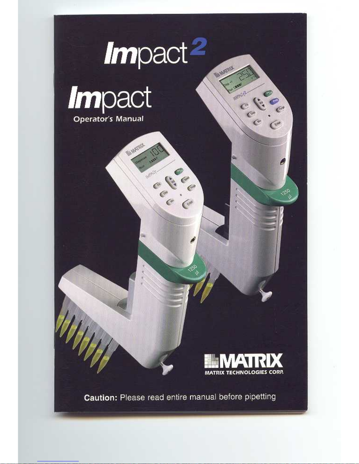
Figure A Figure B Figure C
The Matrix Impact and Impact2 Equalizer allows the Tip to Tip spacing of the pipettor to change. This allows pipeting into
or between vessels of varying center to center configurations. The set button(s), indicator and control rod all work together
to change the distance between the tips (see figure A).
To attach tips, the control rod should be in position such that the indicator is set at 9 mm (figure B). In the case of the
Equalizer384 (the Equalizer with two set buttons), tips arranged in racks of 384 can be attached when the indicator is set at
the 4.5 mm mark. Once tips are attached, follow the steps below to change the pipettor to a new tip spacing.
Matrix Equalizer:
1. Depress the set button using your thumb or finger.
2. While depressing, slide the set button to the desired tip-to-tip spacing marker on the window. Release the set button to
lock the spacing.
3. Using the control rod, slide the tips into the desired position. The indicator in the window will also move and will nest
into the set button when the desired position is achieved.
Matrix Equalizer384:
1. To set the tip spacing for the vessel with the widest spacing, depress the outer set button (the button closes t to the
control rod) using your finger or thumb.
2. While depressing, slide the set button to the desired tip-to-tip spacing marker on the window. Release the set button to
lock the spacing.
3. Check the spacing by using the control rod to slide the tips into position. The indicator in the window will also move
and will nest into the set button when the desired position is achieved.
4. For the vessel with the tightest spacing (from 4.5mm - the spacing for 384 well plates), depress the other set button
using your thumb or finger and repeat steps 2 and 3.
5. In the case of 8 channel Equalizer384 pipettors, when pushing or pulling the control rod past the 9 mm position, if
pressure is applied to the back side of the control rod (see figure B), a detent will be noticeable. This will indicate the
96 well or tip mounting position. Conversely, by applying pressure to the front side of the control rod (see figure C),
the detent can be by-passed for smoother slide operation.
Note: For maximum accuracy when adjusting the spacing of the tips from a compressed position to an expanded position it
is recommended that the control rod be actuated beyond the desired spacing and then compressed to the desired dimension.
This will maximize the spatial accuracy between the individual tips.
Important: Do not attempt to slide the set button(s) without depressing. Moving the set button(s) without first disengaging
will cause premature wear on the mechanism.
Important: Do not attempt to disassemble the unit. Please contact our Technical Services Department at 800-345-0206 for
all service related issues.
Man19755 Rev. B
 Loading...