

Page 1
CAUTION !
Read all precautions and instructions in this manual before using this equipment. Keep this manual
for future reference.
Improper assembly, maintenance or use can void the warranty terms.
Version 1.0 2013 IC-MXIC3B-01 Copyright by Indoorcycling Group GmbH 2013 | www.indoorcycling.com ENG 1
Matrix IC3
model no.:
IC-MXIC3B-01
Manufactured by:
Indoorcycling Group GmbH
Happurger Str. 86
90482 Nuremberg | Germany
www.indoorcycling.com
info@indoorcycling.com
MATRIX Fitness Systems Corp.
1610 Landmark Drive
Cottage Grove, WI 53527
Toll-free: 866.693.4863
Local: 608.839.8686
www.matrixtness.com
ENG ESP
Page 2

TABLE OF CONTENTS
Important precautions page 3
Before you begin page 4
How to assemble the Matrix IC3 Indoor Cycle page 5-7
How to operate page 12
Initial install checks page 8
How to adjust the Matrix IC3 Indoor Cycle page 9-11
Resistance adjustment page 12
How to move the Matrix IC3 Indoor Cycle page 12
Preventative maintenance page 13
Daily maintenance page 13
Weekly maintenance page 13
Bi-Weekly maintenance page 14-15
Monthly maintenance page 15-16
Maintenance activity plan & check lists page 17-18
Exploded drawings of structural components page 19-23
Spare part reference list page 24-28
Limited warranty page 29
Technical specications:
The Matrix IC3 Bike is, according to EN 957, a Class S product for professional
and / or commercial use. Such training equipment is intended for use in training areas
of organizations such as tness clubs or sport associations, where access
and control are specically regulated by the individual with legal responsibility.
Foot print: 52 x 120 cm / 20.5 x 47.2 inch
Weight of bike: 57kg / 126,66 lbs
Max saddle height: 115 cm / 45.3 in
Max handlebar height: 115 cm / 45.3 in
Max user weight: 130 kg / 287 lbs
The bike is designed to accommodate most users from 150 to 205 cm / 59.1 to 81.7 in
in body height.
Version 1.0 2013 IC-MXIC3B-01 Copyright by Indoorcycling Group GmbH 2013 | www.indoorcycling.com ENG 2
Page 3

IMPORTANT PRECAUTIONS
WARNING!
To reduce the risk of serious injury, read the following important precautions and information before
operating the Matrix IC3 Indoor Cycle.
It is the responsibility of the owner to ensure that all users of the Matrix IC3 Indoor Cycle are
informed of all warnings and precautions.
Operate and maintain the Matrix IC3 Indoor Cycle only as described in this manual.
Do not operate the Matrix IC3 Indoor Cycle until it is properly assembled (see page 5-7).
Keep the bike indoors, away from moisture and dust. Do not place the Matrix IC3 Indoor Cycle in
a garage or covered patio or near water.
Place the Matrix IC3 Indoor Cycle on a level surface. To protect the oor or carpet from damage,
place a mat beneath the Matrix IC3 Indoor Cycle. Make sure that there is adequate room around
the Matrix IC3 Indoor Cycle to mount, dismount, and operate it.
Regularly inspect and properly tighten all parts of the Matrix IC3 Indoor Cycle as recommended
in this manual. Please replace defective parts immediately, and do not use the bike until repair is
performed. Use only original parts from the manufacturer.
Children under the age of 14 should only be allowed use of the Matrix IC3 Indoor Cycle with
parental consent and guidance by a specially trained instructor.
The Matrix IC3 Indoor Cycle should not be used by persons weighing more than 290 pounds
(130 kg).
Always wear appropriate athletic attire and shoes while operating the Matrix IC3 Indoor Cycle. Do
not wear loose clothing that could become caught on the Matrix IC3 Indoor Cycle or shoes with
loose laces.
Before using the Matrix IC3 Indoor Cycle, make sure that you are familiar with the operation of
the Indoor Cycle (see pages 8-12).
The Matrix IC3 Indoor Cycle does not have an independently moving ywheel (wheel); the pedals
will continue to move with the ywheel until the ywheel stops.
Always adjust the ywheel resistance so that your pedaling motion is controlled (see page 12).
Keep your back straight while using the Matrix IC3 Indoor Cycle; do not arch your back.
If you feel pain or dizziness while exercising, stop immediately, rest and cool down.
If replacement parts are needed, use only manufacturer-supplied parts.
1.
2.
3.
4.
5.
6.
7.
8.
9.
10.
11.
12.
13.
14.
15.
WARNING:
Before beginning any exercise program, consult your physician. This is especially important for
persons over the age of 35 or persons with pre-existing health problems. Read all instructions
prior to use. Be aware that incorrect or extensive training can result in serious health injuries. The
manufacturer assumes no responsibility for personal injury or property damage sustained by or
through the use of this product.
Version 1.0 2013 IC-MXIC3B-01 Copyright by Indoorcycling Group GmbH 2013 | www.indoorcycling.com ENG 3
ENG ESP
Page 4
BEFORE YOU BEGIN
Dear Customer,
Congratulations on selecting the Matrix IC3 Indoor Cycle.
The Matrix IC3 Indoor Cycle offers an impressive array of features designed to
enhance cardiovascular tness, tone muscles, and develop endurance. Whether users
are beginners or experienced athletes, the Matrix IC3 Indoor Cycle offers workouts that
will help users to reach their individual tness goals.
IMPORTANT: Read this manual carefully before assembling or using the Matrix IC3
Indoor Cycle.
If you have questions after reading this manual, please contact Indoorcycling Group GmbH or
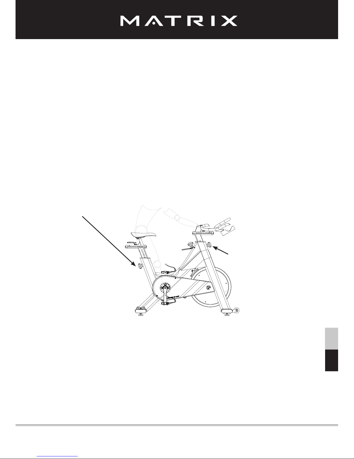
visit the website www.indoorcycling.com. Before reading further, please familiarize
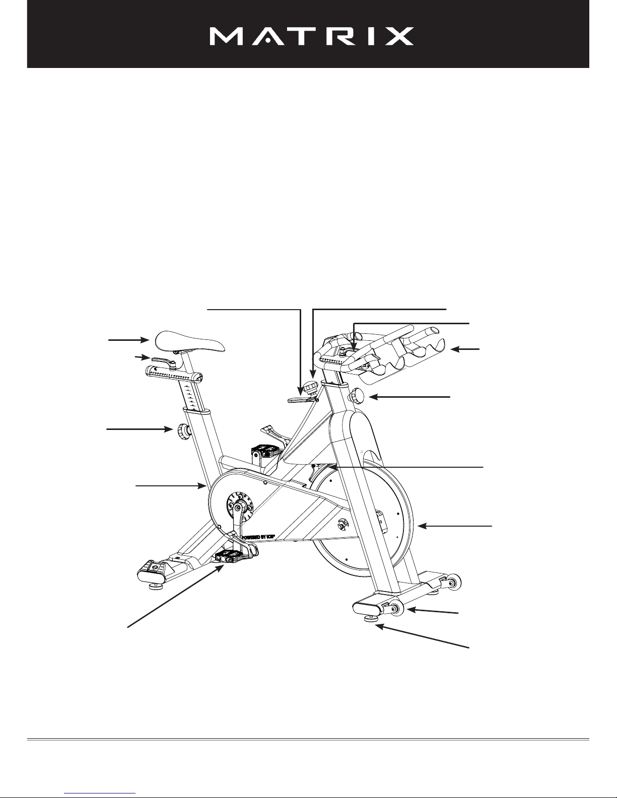
yourself with the parts that are labeled in the drawing below.
Version 1.0 2013 IC-MXIC3B-01 Copyright by Indoorcycling Group GmbH 2013 | www.indoorcycling.com ENG 4
Emergency brake handle
Lever handle
Saddle
Adjustment
knob
Combi
pedal
Chain guard
Resistance knob
Handlebar
Adjustment knob
Brake pad
Flywheel
Transport wheel
Leveling feet
You will nd the production code on the lower left side of the Matrix IC3 Indoor Cycle
frame. Please refer to this number in servicing and maintenance lists.
Lever handle
Page 5
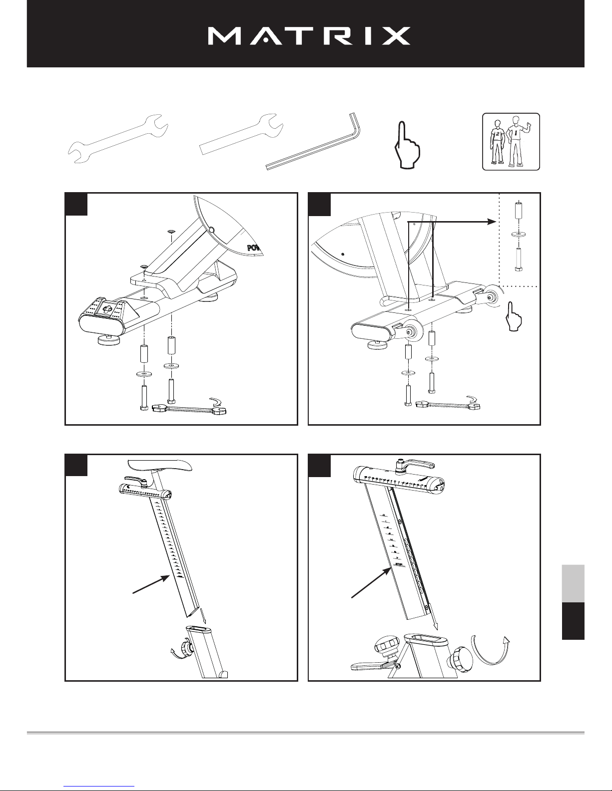
HOW TO ASSEMBLE Matrix IC3 Indoor Cycle
Version 1.0 2013 IC-MXIC3B-01 Copyright by Indoorcycling Group GmbH 2013 | www.indoorcycling.com ENG 5
SW 17mm
SW 13mm
3mm
5mm
hand tight
1x
15mm Pedal
Wrench
1x
Please assure that nuts are tightened with signicant force to minimize loosening during use.
ENG ESP
1
3
2
4
STOP mark
STOP mark
Seat clamp must be tightened securely from both sides to minimize loosening during use.
Page 6

Version 1.0 2013 IC-MXIC3B-01 Copyright by Indoorcycling Group GmbH 2013 | www.indoorcycling.com ENG 6
HOW TO ASSEMBLE Matrix IC3 Indoor Cycle
SW 17mm
SW 13mm
hand tight
1x
1x
15mm Pedal
Wrench
7
5
6
3mm
5mm
Page 7
Version 1.0 2013 IC-MXIC3B-01 Copyright by Indoorcycling Group GmbH 2013 | www.indoorcycling.com ENG 7
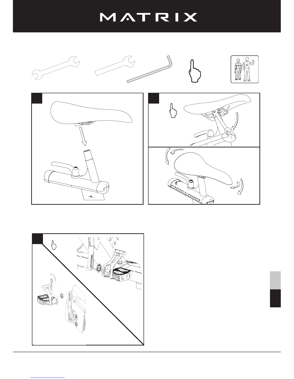
HOW TO ASSEMBLE Matrix IC3 Indoor Cycle
SW 17mm
SW 13mm
3mm
5mm
hand tight
1x
1x
Pedal marked R installed on right crank
(clockwise), Pedal marked L installed on left
crank (counterclockwise).
Pedals must be fastened with signicant
force to avoid loosening with use of the
indoor cycle.
15mm Pedal
Wrench
ENG ESP
8 9
10
R
L
13 mm
Make sure the seat is xed in a LEVEL HORIZONTAL AND VERTICAL position.
Seat clamp must be tightened securely from both sides to minimize loosening during use.
Please follow
instructions
Page 8

The cycle tune-up must be performed at initial installation of the indoor cycle for optimal performance and
longevity. Please read and follow all instructions below. If the indoor cycle is not installed and tuned as
described, components may wear excessively and the indoor cycle may become damaged. If you have
questions about the installation, please contact matrix customer service www.matrixtness.com
Note: Some maintenance procedures require acid-, silicone- and solvent-free spray lubricant (for
example, BRUNOX) and white lithium grease.
1. Make sure that the indoor cycle is level. If the indoor cycle rocks on the oor, turn the
leveling feet underneath the front and/or rear stabilizer until the rocking motion is eliminated.
2. Verify emergency brake function to assure that emergency brake functions correctly.
3. Brake pad calibration: Turn resistance knob counterclockwise as far as possible (minimum bra-
king effect). Verify that there is a slight separation of the brake pad from ywheel. Brake pad
should barely touch the ywheel when resistance knob is turned counterclockwise as far as it
can go.
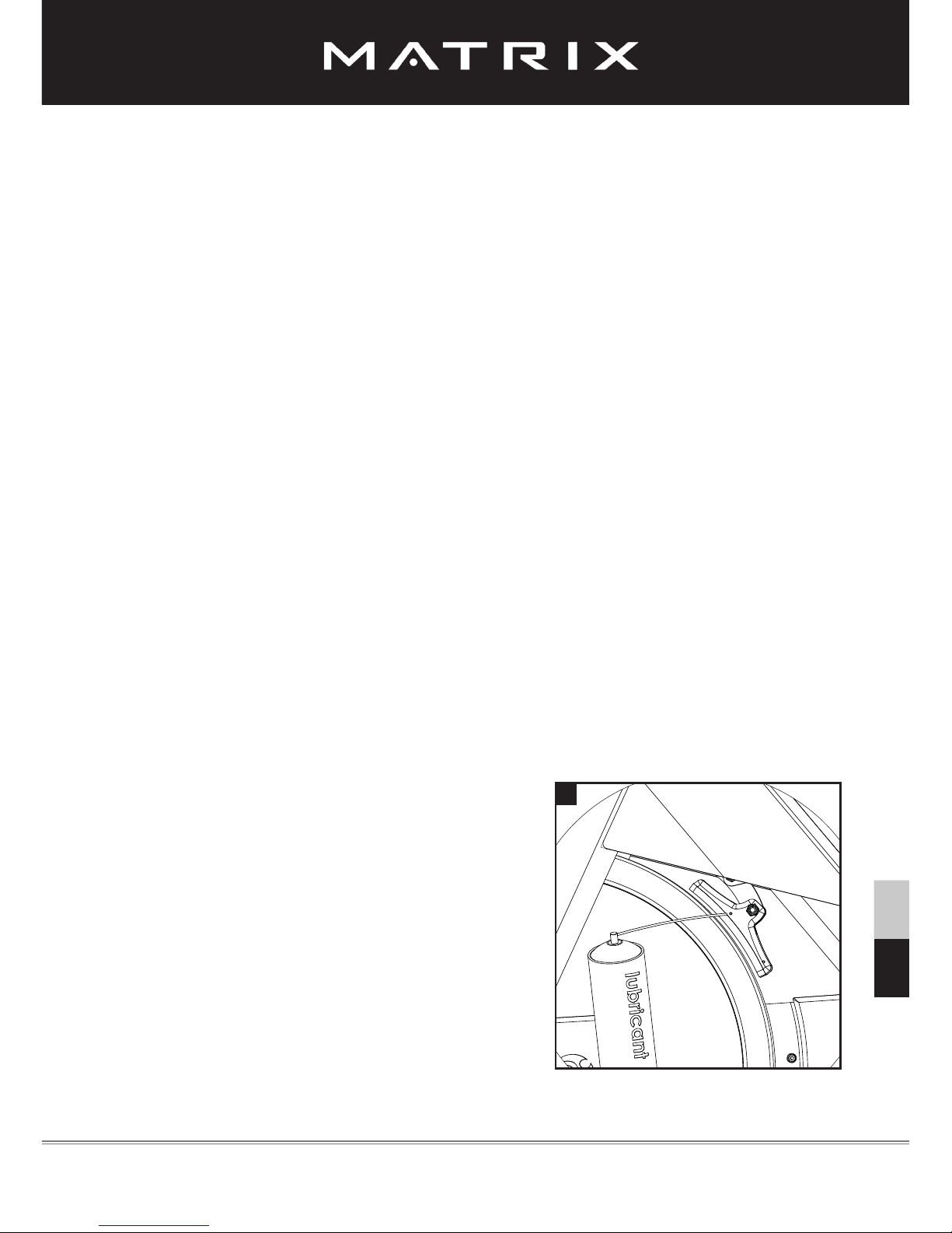
4. Apply spray lubricant to the brake pad using the lubrication holes on the plastic part or the brake
pad and externally on the felt pad. Make sure brake pad is thoroughly soaked from end to end
with lubricant spray. Wipe the excess from the ywheel.
* Best Practice: Use a rellable spray bottle lled with non-aerosol acid-, silicone- and solvent-
free spray lubricant purchased by the gallon (3.7 L) at the local hardware store.
5. Apply Lithium grease to the threads on the lower end of the brake rod. First, turn the resistance
knob clockwise until it stops. Apply a small amount of white lithium grease to the threads on the
brake rod above the two lock nuts. Then, turn the resistance knob counterclockwise until it stops.
6. Apply Lithium grease on the metal threads of all the adjustment knobs.
7. Check four (4) Allen bolts on RS pulley for tightness. If loose, apply LocTite Threadlocker
Blue-242 and retighten.
8. Verify R and L crank arm Allen bolts for tightness. If loose, apply LocTite Threadlocker Blue-242
and retighten.
9. Wipe down bike frame with rag moistened with solvent-free spray lubricant
10. Some parts of the indoor cycle may become loose during shipment. Check crank arms and check
all exposed screws, bolts and nuts, and make sure that they are properly tightened.
Customer Service
1. Provide basic maintenance instructions for clients and direct them to detailed maintenance
instructions (page 13-18).
2. Provide sign-off sheet for clients to conrm explanation of maintenance procedures/manual and
verication of condition of bikes.
Version 1.0 2013 IC-MXIC3B-01 Copyright by Indoorcycling Group GmbH 2013 | www.indoorcycling.com ENG 8
INITIAL INSTALL CHECKS
Page 9
HOW TO ADJUST THE Matrix IC3 Indoor Cycle
The Matrix IC3 Indoor Cycle can be adjusted for maximum comfort and exercise effectiveness. The instructions below describe one approach to adjusting the Matrix IC3 Indoor
Cycle to ensure optimal user comfort and ideal body positioning.
You may choose to adjust the Matrix IC3 Indoor Cycle differently.
Pedal strap adjustment:
Sit on the saddle and position your feet on the pedals, with the balls of your feet directly
above the spindles of the pedals (see the drawing below). Adjust the pedal straps so the
toe clips (cages) are snug but not too tight. Note: When tting a bike with combi-
pedals, the pedals feature toe clips on one surface and SPD cleats on the opposite
surface. If desired, use the SPD cleats with cycling shoes instead of the toe clips.
Saddle height adjustment:
Sit on the saddle and slowly pedal until the right pedal is in the lowest position. Your knees
should be slightly bent with no dropping of the hips.
To avoid hyperextending your knees, make sure that your legs are not completely
straight.
Version 1.0 2013 IC-MXIC3B-01 Copyright by Indoorcycling Group GmbH 2013 | www.indoorcycling.com ENG 9
Please avoid overtightening the pop pin adjustment knob as this may cause damage
to the vertical aluminum stems.
ENG ESP
Please do not adjust saddle
height beyond the STOP mark
on the stem. Also ensure the
pop pin is fully engaged and
securely tightened (page 5).
Please do not adjust saddle
height beyond the STOP mark
on the stem and ensure the
pop pin is fully engaged and
securely tightened (page 5).
Page 10
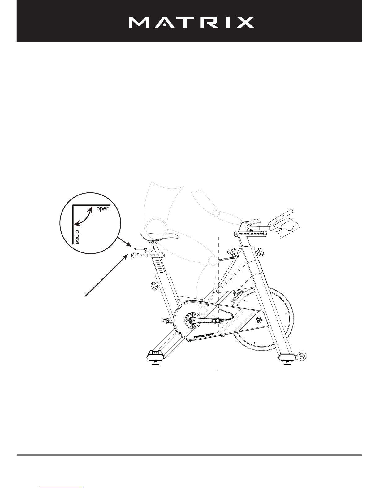
Saddle horizontal adjustment:
Proper horizontal adjustment of the saddle is very important in avoiding injury to the knees.
Sit on the saddle and move the pedals until the crank arms are in horizontal position.
Using your forward leg as a marker, your kneecap should be directly above the
center of the pedal so that a straight line is created between knee and center of the pedal
(see the dotted line in image below). To adjust the horizontal position of the saddle, rst
dismount the Matrix IC3 Indoor Cycle. Next, loosen the rear lever handle, slide the saddle
forward or backward as required, and then retighten the lever handle.
Version 1.0 2013 IC-MXIC3B-01 Copyright by Indoorcycling Group GmbH 2013 | www.indoorcycling.com ENG 10
HOW TO ADJUST THE Matrix IC3 Indoor Cycle
horizontal adjustment
with lever handle
Page 11
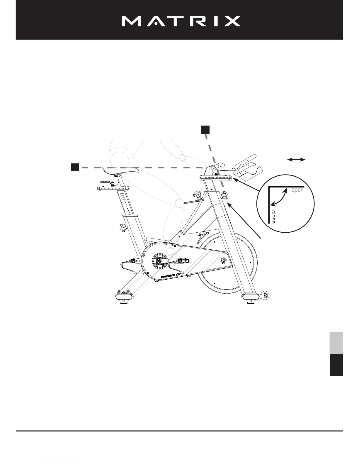
Handlebar adjustment:
Begin with the top of the handlebar at relatively the same height as, or just slightly higher than,
the top of the saddle (dotted horizontal line A in the drawing below) and at a neutral
fore/aft position (see dotted vertical line B in drawing below). If your knees touch the
handlebars, or if you experience back discomfort while pedaling for extended periods of
time, the height of the handlebars can be adjusted. First, dismount the Matrix IC3 Indoor
Cycle.
Next, turn the front adjustment knob counterclockwise, slide the handlebar post up or
down, and retighten the adjustment knob.
Next, the horizontal position of the handlebar should be adjusted. If the handlebar is
too close to the saddle, your breathing may feel restricted. If the handlebar is too far
from the saddle, you may experience back discomfort. To adjust the horizontal position
of the handlebar, rst dismount the Matrix IC3 Indoor Cycle. Check for proper handlebar position by positioning your elbow so that it touches the front tip of the saddle at a 90- degree
angle and checking that the ngertip of your middle nger is touching the handlebar at the
mid-point. If it is not as described, loosen the fore/aft lever handle and slide the handlebar
forward or backward until your middle nger is touching the handlebar at the mid-point.
Retighten the lever handle.
The handlebar offers a wide variety of hand positions for personal preferences. Changing
your hand position can change the angle of your back, neck, and arms. To minimize the
stress on your muscles during your workouts, change your hand position frequently.
handlebar
fore/aft
lever handle:
Version 1.0 2013 IC-MXIC3B-01 Copyright by Indoorcycling Group GmbH 2013 | www.indoorcycling.com ENG 11
handlebar
up/down
adjustment knob
HOW TO ADJUST THE Matrix IC3 Indoor Cycle
ENG ESP
A
B
Page 12
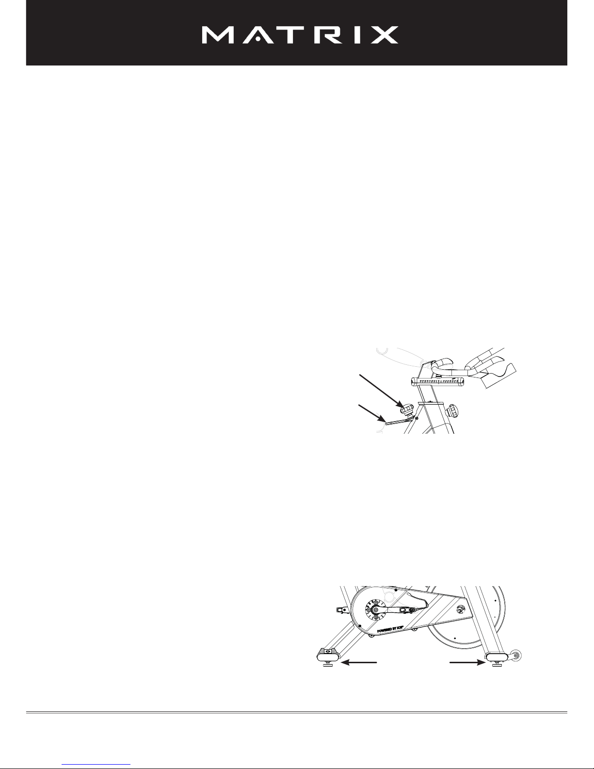
Resistance adjustment:
The preferred level of difculty in pedaling (resistance) can be regulated in ne
increments by use of the resistance knob. To increase the resistance, turn the resistance
knob clockwise. To decrease the resistance, turn the knob counterclockwise.
IMPORTANT: To stop the ywheel (wheel) while pedaling, pull up the red emergency
handle. The ywheel should quickly come to a complete stop. Please make sure your
shoes are xed into the toe clip or, in case cycling shoes are used, your shoe cleat is
connected to the pedal binding while riding.
HOW TO OPERATE THE Matrix IC3 Indoor Cycle
The Matrix IC3 Indoor Cycle does not have a free-moving ywheel (wheel).
The pedals will continue to move with the ywheel until the ywheel stops.
Reducing speed in a controlled manner is required. To stop the ywheel
immediately, pull up the red emergency break handle. Always pedal in a
controlled manner and adjust your desired cadence according to your own
abilities. Pull the red emergency handle up for emergency stop.
!
!
How to move the Matrix IC3 Indoor Cycle:
Due to the weight of the Matrix IC3 Indoor Cycle, it is recommended that two people
move it. While one person lifts the back of the Matrix IC3 Indoor Cycle, the second person
rmly holds the handlebar and tips the Matrix IC3 Indoor Cycle forward until it rolls on the
wheels. Carefully move the Indoor Cycle to the desired location and then lower it.
CAUTION: To reduce the risk of injury, use extreme caution while moving the Indoor
Cycle. Do not attempt to move it over uneven surfaces. Make sure to allow a minimum safety space of 20 inches to the nearest equipment.
If the Matrix IC3 Indoor Cycle rocks on
the oor after being set down, turn the
leveling feet (see diagram) underneath the front or rear stabilizer until the
rocking motion is eliminated. Im-
portant: Please do not unscrew
the leveling feet more than ½ inch!
Resistance knob
Red emergency
brake handle
Leveling feet
Version 1.0 2013 IC-MXIC3B-01 Copyright by Indoorcycling Group GmbH 2013 | www.indoorcycling.com ENG 12
Page 13
PREVENTATIVE MAINTENANCE
Version 1.0 2013 IC-MXIC3B-01 Copyright by Indoorcycling Group GmbH 2013 | www.indoorcycling.com ENG 13
Regular maintenance must be performed on the Matrix IC3 Indoor Cycle for optimal
performance and longevity. Please read and follow all instructions below. If the in-
door cycle is not maintained as described, components may wear excessively and
the Matrix IC3 Indoor Cycle may become damaged. Improper maintenance will void
the warranty terms. If you have questions about maintenance, contact your local
distributor or refer to www.indoorcycling.com.
Note: Many maintenance procedures require lubricant spray.
Manufacturer recommends Brunox or any other solvent-free lubricant.
Daily maintenance:
1. Make sure that the Matrix IC3 Indoor Cycle is level. If the Matrix IC3 Indoor Cycle rocks
on your oor, turn the leveling feet underneath the front or rear stabilizer until the rocking
motion is eliminated (see „How to move the Matrix IC3 Indoor Cycle“ on page 12).
2. After each user nishes exercising, the Matrix IC3 Indoor Cycle should be disinfected and
cleaned to maintain a hygienic environment. First, apply a disinfectant spray to the handlebars and the saddle. Using a lint-free cloth, dry the handlebars and the saddle. Next, apply a
small amount of disinfectant to a lint-free cloth and clean the adjustment knobs and the lock
handles. Avoid using strong detergents on the Matrix IC3 Indoor Cycle frame.
Weekly maintenance:
1. Apply a small amount of the lubrication spray to a lint-free cloth. Thoroughly clean
the frame, the handlebar slider, the seat sliders, the ywheel, and the plastic parts of the
Matrix IC3 Indoor Cycle.
2. For optimal performance of the resistance
system, and to minimize wear on the brake pad,
the acid-, silicone- and solvent-free spray lubricant
should be applied to the brake pad using the lubrication holes on the plastic part of the brake pad. If
fuzz or lint appears on the brake pad, the brake pad
has become too dry. Lubricant spray should be applied more frequently. Make sure brake pad is thoroughly soaked from end to end with lubricant spray.
Wipe off any excess.
ENG ESP
2
Page 14
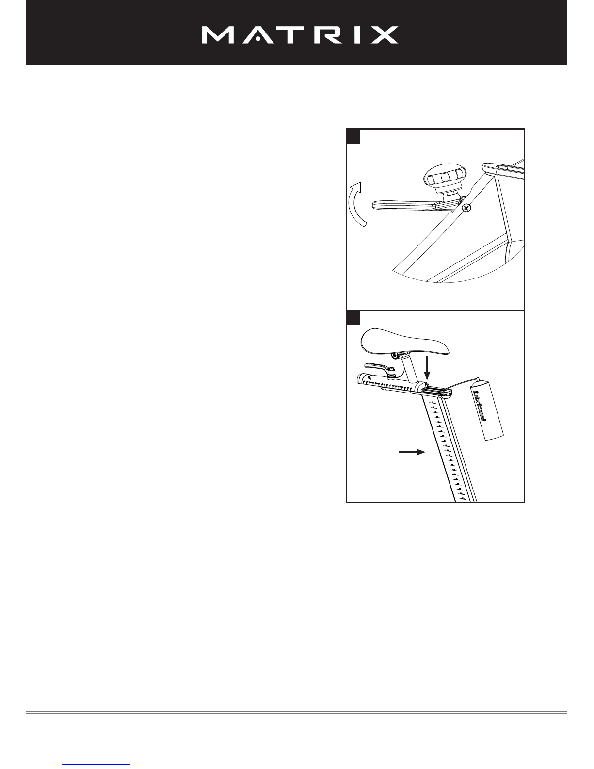
2. To maintain the easy adjustability of the saddle
post, the saddle post should be cleaned and
lubricated. Turn the rear adjustment knob counterclockwise and slide the saddle post out of the
frame. Apply a small amount of lubricant spray to a
lint-free cloth, and clean the saddle post (A).
Next, loosen the rear lock handle and slide
the saddle carriage as far back as possible. Apply a small amount of lubricant spray to a lint-free
cloth, and clean the top of the saddle slide (B).
Then slide the saddle carriage as far forward as
possible and clean the top of the saddle slide. Finally, adjust the saddle to the desired position.
Version 1.0 2013 IC-MXIC3B-01 Copyright by Indoorcycling Group GmbH 2013 | www.indoorcycling.com ENG 14
Bi-weekly maintenance:
1. The Matrix IC3 Indoor Cycle should not be used
if the emergency brake system is not working properly.
While sitting on the saddle and pedaling, test the
brake by pulling upward on the emergency brake
handle. The ywheel should come to a quick and
complete stop.
PREVENTATIVE MAINTENANCE
1
2
A
B
Page 15
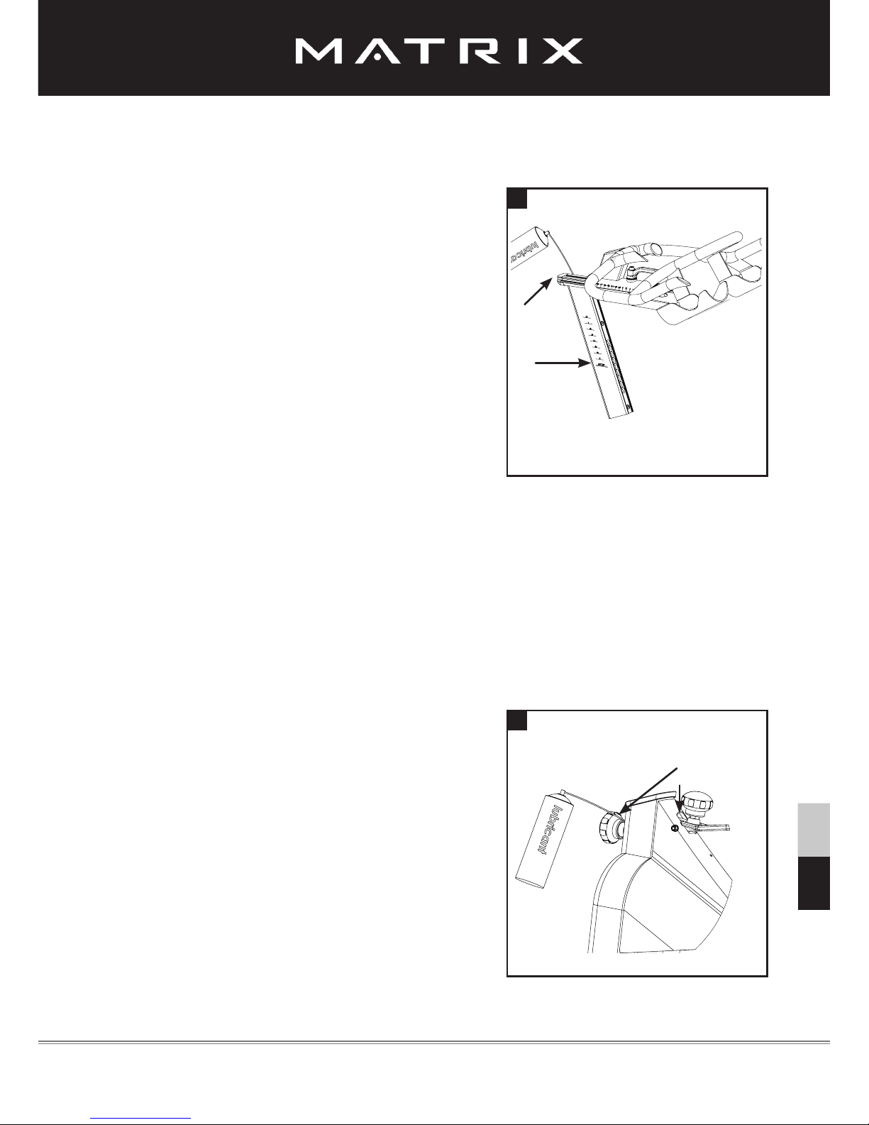
3. To maintain the easy adjustability of the handlebar post, the handlebar post should be cleaned
and lubricated. First, turn the front adjustment knob
counterclockwise and slide the handlebar post out
of the frame. Apply a small amount of lubricant
spray to a lint-free cloth, and clean the handlebar
post (A).
Next, reinsert the handlebar post into the frame
and adjust it to the desired height. Loosen
the front lock handle and slide the handlebar
carriage as far back as possible. Apply a small
amount of lubricant spray to a lint-free cloth, and
clean the surface of the handlebar slide (B). Then
slide the handlebar carriage as far forward as
possible and clean the top of the handlebar slide.
Finally, adjust the handlebar to the desired position.
Monthly maintenance:
1. To maintain the smooth function of the height
adjust ment knobs for the handlebar and saddle, the
metal threads on the adjustment knobs (A) must
be lubricated. Use of white lithium grease is recommended.
Version 1.0 2013 IC-MXIC3B-01 Copyright by Indoorcycling Group GmbH 2013 | www.indoorcycling.com ENG 15
PREVENTATIVE MAINTENANCE
ENG ESP
3
1
A
A
B
Page 16
Version 1.0 2013 IC-MXIC3B-01 Copyright by Indoorcycling Group GmbH 2013 | www.indoorcycling.com ENG 16
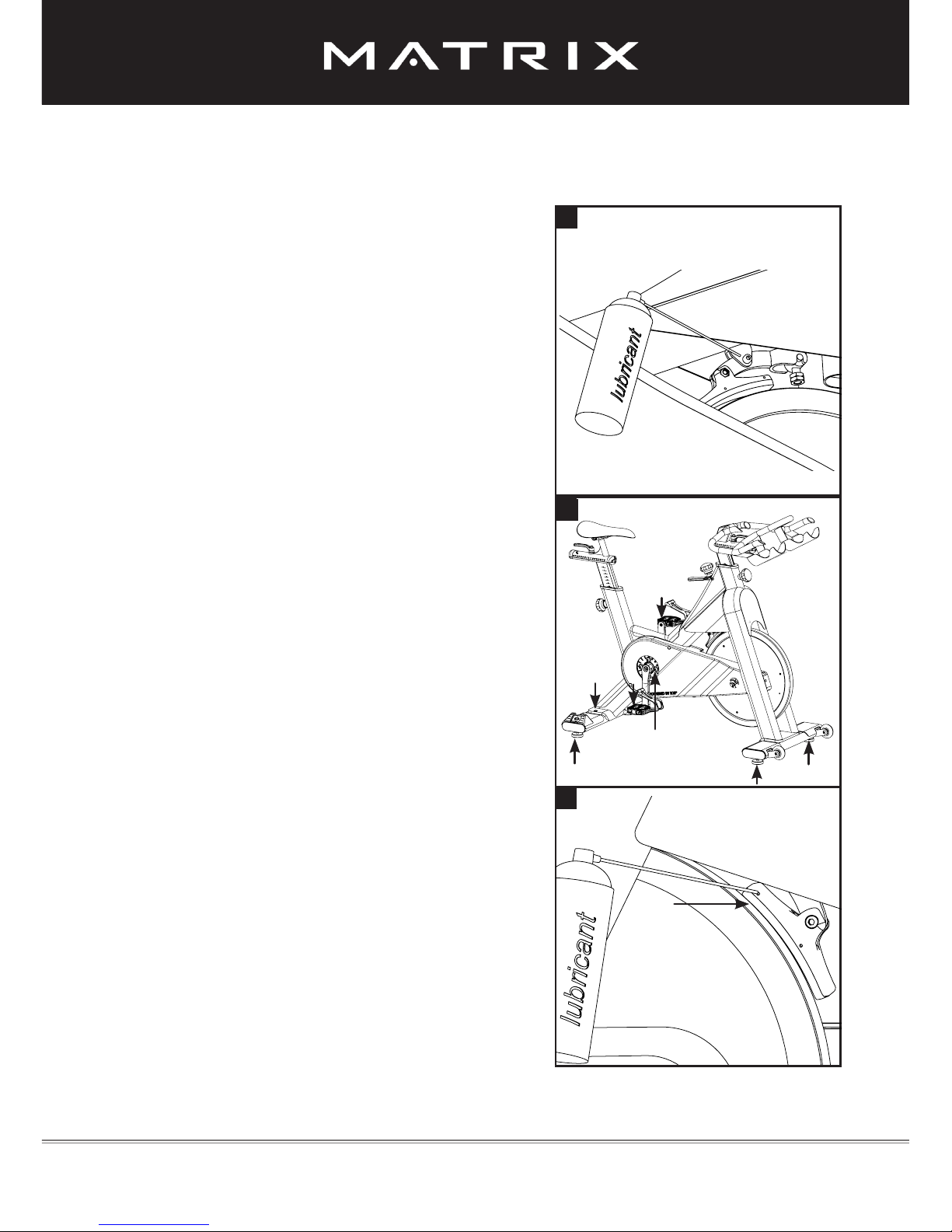
4. The brake pad will become worn as a result of
repeated use. The Matrix IC3 Indoor Cycle should
not be used if the emergency brake system is not
working properly (see page 14)! Should you feel
that the resistance system’s functions are decient,
it is essential to ne-tune the resistance system be-
fore the bike is used again! Please check the setting
of the brake system as follows: First turn the resistance regulator on the brake system as far as it will
go to the left (minimum braking effect). If the setting
is correct, the brake pads should be ush
with the ywheel and barely touching so that it is
possible to cycle with a barely noticeable amount
of resistance. The brake pad can be adjusted using
a 10 mm wrench. Next, check the brake pad for
signs of wear. If the brake pad does show signs of
excessive wear, thoroughly soak the brake pad
with lubricant spray using the 2 lubrication holes
(B). Wipe off the excess.
3. Some parts of the Matrix IC3 Indoor Cycle may
become loose as a result of repeated use. Check
pedals, toe clips and pedal straps, and make sure
that they are properly tightened. Next, check all exposed screws, bolts, and nuts. Make sure
that they are properly tightened. Finally, check the
saddle to make sure that it is not loose or damaged.
Please use Locktite on loose crank arm and pulley
screws.
2. To maintain the easy adjustability of the
resistance system, the threads on the lower end
of the brake rod should be lubricated. First, turn the
resistance knob clockwise until it stops. Next, look
under the right or left side of the frame and locate
the brake rod, which has two lock nuts on its lower
end. Apply a small amount of synthetic grease
(white lithium grease) to the threads on the brake
rod above the two lock nuts. Turn the
resistance knob counterclockwise until it stops.
PREVENTATIVE MAINTENANCE
2
5
4
B
3
Page 17
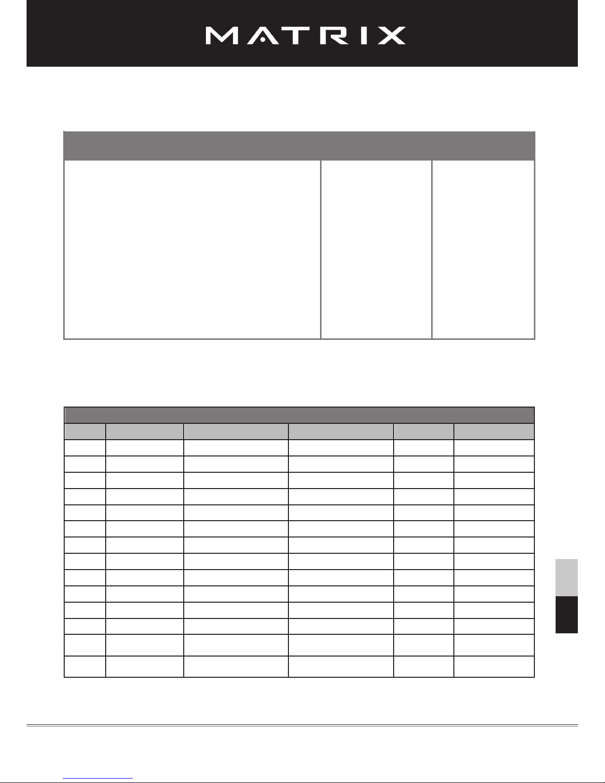
MAINTENANCE ACTIVITY AND REQUIRED SCHEDULE
Activity Rotation Details found on
Examples of maintenance plan charts for in-house service technicians:
Weekly maintenance Checklist
Bike No. Production code Observations Action taken Result Name / date
Version 1.0 2013 IC-MXIC3B-01 Copyright by Indoorcycling Group GmbH 2013 | www.indoorcycling.com ENG 17
Feet leveling, disinfection and cleaning of the bike daily page 13
Servicing brake pads, detailed cleaning of the entire bike weekly page 13
Check emergency brake function bi-weekly page 14+16
Clean and lubricate saddle and handlebar sliders / posts bi-weekly page 14-15
Check adjustment knobs monthly page 15
Check brake pad for signs of wear monthly page 13
Check brake system, lubricate monthly page 16
Check pedals, toe clip and straps for signs of wear monthly page 16
Check to ensure connections and components are secure &
correctly tightened monthly page 16
ENG ESP
Page 18
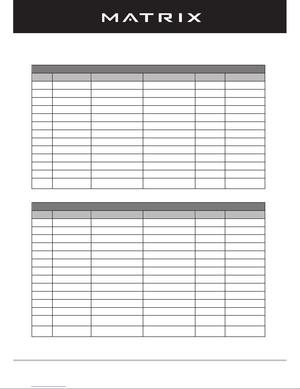
Monthly maintenance Checklist
Bike No. Production code Observations Action Taken Result Name / date
Bi-Weekly maintenance Checklist
Bike No. Production code Observations Action Taken Result Name / date
Version 1.0 2013 IC-MXIC3B-01 Copyright by Indoorcycling Group GmbH 2013 | www.indoorcycling.com ENG 18
MAINTENANCE ACTIVITY AND REQUIRED SCHEDULE
Page 19

SPARE PARTS
Version 1.0 2013 IC-MXIC3B-01 Copyright by Indoorcycling Group GmbH 2013 | www.indoorcycling.com ENG 19
Drive Gear Parts
Brake parts
ENG ESP
130-01-00001-01
130-03-00001-01
130-01-00007-01
130-01-00008-01
130-01-00003-01
130-01-00005-01
130-01-00004-01
Page 20

Flywheel
Version 1.0 2013 IC-MXIC3B-01 Copyright by Indoorcycling Group GmbH 2013 | www.indoorcycling.com ENG 20
Handlebar
SPARE PARTS
150-01-00010-01
150-03-00016-01
150-01-00033-01
900-06-00002-01
100-01-00005-01
150-01-00031-01
150-01-00032-01
150-01-00009-01
150-03-00048-01
150-03-00048-01
Page 21

Frame
Version 1.0 2013 IC-MXIC3B-01 Copyright by Indoorcycling Group GmbH 2013 | www.indoorcycling.com ENG 21
Chain Guard
SPARE PARTS
ENG ESP
100-03-00017-01
100-03-00018-01
180-01-00001-02
100-03-00021-01
100-03-00016-02
160-01-00001-01
160-01-00002-01
160-01-00003-01
Page 22

Version 1.0 2013 IC-MXIC3B-01 Copyright by Indoorcycling Group GmbH 2013 | www.indoorcycling.com ENG 22
Saddle Support
Pedals
SPARE PARTS
150-01-00005-01
150-03-00048-01
Page 23

Version 1.0 2013 IC-MXIC3B-01 Copyright by Indoorcycling Group GmbH 2013 | www.indoorcycling.com ENG 23
Rear Stabilizer
SPARE PARTS
ENG ESP
190-01-00004-01
140-01-00003-01
140-01-00005-01
900-10-00001-01
140-02-00003-01
140-01-00004-01
140-01-00004-01
Front Stabilizer
Page 24

Version 1.0 2013 IC-MXIC3B-01 Copyright by Indoorcycling Group GmbH 2013 | www.indoorcycling.com ENG 24
Spare Part No. Description
Brake 130-01-00001-01 UPPER BRAKE ROD ASSEMBLY:
BRAKE ADJUSTMENT KNOB 1x
NUT, M10 x 1.5P, ss304 STAINLESS STEEL, DIN934/ ISO4032 1x
BRAKE ROD 1x
ADJUSTMENT BALL 1x
130-03-00001-01 BRAKE ADJUSTMENT KNOB
130-01-00007-01 LOWER BRAKE KIT:
BRAKE ROD FRAME FITTING 1x
WASHER, 22mm x 10mm x 2mm, ss304 STAINLESS STEEL, DIN125
/ ISO 7090 1x
COMPRESSION SPRING, 16mm x 30mm x 1.5mm, LOWER BRAKE
ROD 1x
WASHER, 30mm x 10.5mm x 2mm, ss 304 STAINLESS STEEL,
DIN9021 / ISO 7093 1x
130-01-00008-01 BRAKE ADJUSTMENT DRUM KIT:
ADJUSTMENT DRUM 1x
FLAT NUT, M10 x 0.75P, ss304 STAINLESS STEEL, DIN439/
ISO4035 2x
130-01-00003-01 EMERGENCY BRAKE HANDLE KIT:
EMERGENCY Brake HANDLE 1x
SELF LOCKING NUT, M6 x 1.0P, ss304 STAINLESS STEEL,
DIN985/ ISO7040 1x
WASHER, 12mm x 6,4mm x 1,6mm, ss304 STAINLESS STEEL,
DIN125/ ISO7090 2x
WASHER, 12mm x 6,4mm x 1,6mm, NYLON, DIN125/ ISO7090 2x
PHILIPS HEAD MACHINE SCREW, M6 x 55 x 1.0P, ss304 STAINLESS STEEL, DIN7985H/ ISO7045 1x
130-01-00004-01 BELL CRANK KIT - LOWER BRAKE YOKE:
BELL CRANK 1x
SPACER, 6.1mm x 10.2mm x 10mm 1x
HEX SOCKET HEAD BOLT, M6 x20 x 1.0P, ss304 STAINLESS
STEEL, DIN912/ ISO4762 1x
SELF LOCKING NUT, M6 x 1.0P, #ss304 STAINLESS STEEL,
DIN985/ ISO7040 1x
130-01-00005-01 BRAKE PAD Kit:
SPACER, 6.1mm x 10.2mm x 10mm 1x
HEX SOCKET HEAD BOLT, M6 x20 x 1.0P, ss304 STAINLESS
STEEL, DIN912/ ISO4762 1x
SELF LOCKING NUT, M6 x 1.0P, #ss304 STAINLESS STEEL,
DIN985/ ISO7040 1x
BRAKE PAD ASSEMBLY 1x
Chain Guard 160-01-00001-01 LEFT SIDE FW HUB COVER KIT:
LEFT SIDE FW HUB COVER 1x
ALLEN BOLT, M4 x10 x 0.7P, ss304 STAINLESS STEEL, DIN912/
ISO4762 2x
160-01-00002-01 INNER CHAIN GUARD KIT:
„INNER CHAIN GUARD 1x
RUBBER GASKET INNER CHAIN GUARD 1x
ALLEN BOLT, M4 x10 x 0.7P, ss304 STAINLESS STEEL, DIN912/
ISO4762 5x“
Page 25

Version 1.0 2013 IC-MXIC3B-01 Copyright by Indoorcycling Group GmbH 2013 | www.indoorcycling.com ENG 25
Spare Part No. Description
Chain Guard 160-01-00003-01 OUTER CHAIN GUARD KIT:
RUBBER GASKET OUTER CHAIN GUARD 1x
OUTER CHAIN GUARD 1x
OUTER CHAIN GUARD DECAL 1x
OUTER CHAIN GUARD FRONT COVER 1x
ALLEN BOLT, M4 x10 x 0.7P, ss304 STAINLESS STEEL,
DIN912/ ISO4762 6x
Drive Gear 150-03-00003-01 Left Crank Arm, Red
150-03-00008-01 Right Crank Arm, Red
150-01-00006-01 BOTTOM BRACKET KIT:
Crank Mounting Bolt; M8x20x1.25P 2x
Rubber Cover For M20 Locking Nut 1x
LOCKING NUT, M20 x 1.0P, 8.9 Steel, DIN982/ISO10512 1x
BB BEARING DISTANCE SPACER, 24mm x 20mm x 12mm 1x
BALL BEARING, 6004 2z, 42mm x 20mm x 12mm 2x
BOTTOM BRACKET SPINDLE 1x
900-00-90008-20 Crank Mounting Bolt; M8x20x1,25P
900-01-05020-01 LOCKING NUT, M20 x 1.0P, 8.9 STEEL, DIN982/ISO10512
900-06-00001-01 BALL BEARING, 6004 2z, 42mm x 20mm x 12mm
150-02-00001-01 BOTTOM BRACKET SPINDLE
150-01-00008-01 CRANK PULLEY MOUNTING SET:
WASHER, 10.5mm x 20mm x 1.5mm, ss304 STAINLESS STEEL,
DIN 125 /ISO 7089 4x
BOTTON HEAD BOLT, HEX SOCKET, M10 x 20 x 1.5P,
ss304 Stainless Steel, DIN7346/ ISO738 4x
150-01-00007-01 CRANK PULLEY KIT FOR V-BELT DRIVE:
WASHER, 22mm x 10mm x 2.0mm, ss304 STAINLESS STEEL,
DIN125 / ISO 7089 4x
BUTTON HEAD BOLT, HEX SOCKET, M10 x 20 x 1.5P, ss304 STAINLESS STEEL, DIN 7346 / ISO 7380 4x
PL4 CRANK PULLEY 1x
150-03-00007-01 PL4 CRANK PULLEY
150-03-00001-01 Poly V Belt PL4 1397
Flywheel 900-06-00002-01 BALL BEARING, 6001 2z, 28mm x 12mm x 8mm
150-01-00010-01 FLYWHEEL AXLE ASSEMBLY:
FLYWHEEL AXLE 1x
SELF LOCKING NUT, M12 x 1.0P, STEEL, DIN985/ ISO10511 2x
WASHER, 24mm x 13mm x 2.5mm, STEEL, DIN125 / ISO 7089 2x
SERRATED LOCK WASHER, 20.5mm x 12.5mm x 1.0mm, STEEL,
DIN6798 2x
FW AXLE DISTANCE SLEEVE, LEFT SIDE (39mm) 1x
FW AXLE DISTANCE SLEEVE, RIGHT SIDE (17mm) 1x
150-03-00016-01 FLYWHEEL AXLE
ENG ESP
Page 26

Version 1.0 2013 IC-MXIC3B-01 Copyright by Indoorcycling Group GmbH 2013 | www.indoorcycling.com ENG 26
Spare Part No. Description
Flywheel 150-01-00033-01 FW WHEEL ASSEMBLY FOR V-BELT DRIVE:
FW HUB 1x
SELF TAPPING SCREW 4 x 12mm, STEEL, DIN EN ISO 6x
BALL BEARING, 6001 2z, 28mm x 12mm x 8mm 4x
FW PLASTIC COVER LEFT AND RIGHT 2x
FW PULLEY LOCK RING 1x
POLY V PL4 FW HUB PULLEY 1x
FW COVER DECAL SET 1x
FLYWHEEL 1x
150-01-00031-01 FLYWHEEL MOUNTING KIT LEFT:
SELF LOCKING NUT, M12 x 1.0P, STEEL, DIN985/ ISO10511 1x
WASHER, 24mm x 13mm x 2.5mm, STEEL, DIN125 / ISO 7089 1x
SERRATED LOCK WASHER, 20.5mm x 12.5mm x 1.0mm, STEEL,
DIN6798 1x
FW AXLE DISTANCE SLEEVE, LEFT SIDE (39mm) 1x
150-01-00032-01 FLYWHEEL MOUNTING KIT RIGHT:
SELF LOCKING NUT, M12 x 1.0P, STEEL, DIN985/ ISO10511 1x
WASHER, 24mm x 13mm x 2.5mm, STEEL, DIN125 / ISO 7089 1x
SERRATED LOCK WASHER, 20.5mm x 12.5mm x 1.0mm, STEEL,
DIN6798 1x
FW AXLE DISTANCE SLEEVE, RIGHT SIDE (17mm) 1x
100-01-00005-01 FW BRACKET ADJUSTMENT KIT:
ALLEN BOLT, M8 x 50 x 1.25P, 8.8 STEEL, DIN912/ISO4762 1x
NUT, M8 x 1.25P, 8.8 STEEL, DIN934/ ISO4032 1x
BOTTON HEAD BOLT, M6 x 16 x 1.0P, STEEL, DIN7346/ ISO7380 2x
LOCKING PLATE FOR FW BRACKET 1x
150-01-00009-01 FRONT PULLEY ASSEMBLY FOR V-BELT DRIVE:
FL PULLEY LOCK RING 1x
POLY V PL4 FW HUB PULLEY 1x
Frame 100-03-00016-02 INLAY SLEEVE HB TUBE
100-03-00017-01 PROTECTION COVER - BB TRIANGLE
100-03-00018-01 PROTECTION COVER - REAR LATERAL FRAME TUBE
100-03-00021-01 INLAY SLEEVE SEATPOST TUBE
100-09-00010-01 MX FRAME DECAL SET IC3:
DECAL - WARNING LABEL 1x
DECAL MX - FRONT FORK BADGE 2x
DECAL TRIBAL - FRONT COVER - TRANSFER BADGE 1x
DECAL IC3 - SEAT POST TUBE - ALUMINIUM BADGE (LEFT) 1x
DECAL IC3 - SEAT POST TUBE - ALUMINIUM BADGE (RIGHT) 1x
100-09-00003-01 DECAL TRIBAL - FRONT COVER - TRANSFER BADGE
180-01-00001-02 POP PIN ADJUSTMENT KNOB
Page 27

Version 1.0 2013 IC-MXIC3B-01 Copyright by Indoorcycling Group GmbH 2013 | www.indoorcycling.com ENG 27
Spare Part No. Description
Handle Bar 110-01-00001-01 UPPER HANDLEBAR ASSEMBLY
UPPER HANDLEBAR WELDMENT 1x
COUNTER SUNK HEX SOCKET BOLT, M8 x 25 x 1.0P,
9.8 STEEL, DIN7991/ ISO10642 2x
ADJUSTMENT LEVER ASSEMBLY 1x
HB SLIDER WELDMENT 1x
PLASTIC END CAP UPPER HB + SB SLIDER 2x
ALLEN BOLT, M4 x10 x 0.7P, ss304 STAINLESS STEEL,
DIN912/ ISO4762 2x
110-01-00005-01 UPPER HANDLEBAR KIT:
UPPER HANDLEBAR WELDMENT 1x
COUNTER SUNK HEX SOCKET BOLT, M8 x 25 x 1.0P, 9.8 STEEL,
DIN7991/ ISO10642 2x
110-01-00006-01 Upper HB SLIDER ASSEMBLY:
ADJUSTMENT LEVER ASSEMBLY 1x
HB SLIDER WELDMENT 1x
PLASTIC END CAP UPPER HB + SP SLIDER 2x
ALLEN BOLT, M4 x10 x 0.7P, ss304 STAINLESS STEEL, DIN912/
ISO4762 2x
110-01-00007-01 HB STEM ASSEMBLY:
Plastic Glider 2x
HB Stem Weldment 1x
180-01-00003-01 PROTECTION INSERT KIT, VERTICAL HB STEM:
PROTECTION INSERT, VERTICAL HB STEM 1x
COUNTER SUNK HEX SOCKET, M5 x 10 x 0.8P, ss304 STAINLESS
STEEL, DIN7991/ ISO10642 2x
180-01-00002-01 ADJUSTMENT LEVER ASSEMBLY
190-01-00003-01 PLASTIC END CAP KIT FOR HORIZONTAL HB + SP SLIDER:
PLASTIC END CAP UPPER HB + SP SLIDER 1x
WASHER, 5.3mm x 10mm x 1.0mm, ss304 STAINLESS STEEL,
DIN 125 / ISO 7090 1x
PLASTIC END CAP LOWER HB + SP SLIDER 1x
ALLEN BOLT, M4 x10 x 0.7P, ss304 STAINLESS STEEL,
DIN912/ ISO4762 2x
Seat Post 120-01-00007-01 SEAT POST STEM ASSEMBLY:
Plastic Glider 2x
SP Stem Weldment 1x
180-01-00002-01 ADJUSTMENT LEVER ASSEMBLY
190-01-00003-01 PLASTIC END CAP KIT FOR HORIZONTAL HB + SP SLIDER:
PLASTIC END CAP UPPER HB + SP SLIDER 1x
WASHER, 5.3mm x 10mm x 1.0mm, ss304 STAINLESS STEEL,
DIN 125 / ISO 7090 1x
PLASTIC END CAP LOWER HB + SP SLIDER 1x
ALLEN BOLT, M4 x10 x 0.7P, ss304 STAINLESS STEEL,
DIN912/ ISO4762 2x
120-01-00002-01 SADDLE INCL. SADDLE CLAMP , VELO NR: VL-3125SW:
SADDLE 1x
SADDLE CLAMP 1x
120-01-00003-01 SADDLE CLAMP
ENG ESP
Page 28

Version 1.0 2013 IC-MXIC3B-01 Copyright by Indoorcycling Group GmbH 2013 | www.indoorcycling.com ENG 28
Spare Part No. Description
Seat Post 120-01-00001-01 SP SLIDER ASSEMBLY:
SP SLIDER WELDMENT 1x
ADJUSTMENT LEVER ASSEMBLY 1x
PLASTIC END CAP UPPER HB + SP SLIDER 2x
ALLEN BOLT, M4 x10 x 0.7P, ss304 STAINLESS STEEL, DIN912/
ISO4762 2x
120-01-00004-01 SEATPOST ASSEMBLY:
ALLEN BOLT, M4 x10 x 0.7P, ss304 STAINLESS STEEL,
DIN912/ ISO4762 2x
WASHER, 5.3mm x 10mm x 1.0mm, ss304 STAINLESS STEEL,
DIN 125 / ISO 7090 2x
PLASTIC END CAP LOWER HB + SP SLIDER 2x
COUNTER SUNK HEX SOCKET, M5 x 10 x 0.8P, ss304 STAINLESS
STEEL, DIN7991/ ISO10642 2x
Stabilizer 190-01-00004-01 STABILIZER MOUNTING KIT:
HEX HEAD BOLT M10 x 50 x 1.0P, ss304 STAINLESS STEEL,
DIN933 / ISO4017 1x
WASHER, 22mm x 10.5mm x 2.0mm, ss304 STAINLESS STEEL,
DIN125/ ISO7089 1x
DISTANCE SLEEVE, 11.9mm x 15.9mm x 38mm, blk oxide steel 1x
PLASTIC POP OUT - STABILIZER MOUNTING BRACKET 1x
140-03-00001-01 STABILIZER END CAP
900-10-00001-01 LEVELLING FEET, RUBBER
140-01-00006-01 REAR STABILIZER STRETCH PLATE KIT:
WASHER, 12mm x 6.4mm x 1.6mm, BLK OXIDE STEEL, DIN125/
ISO7090 4x
HEX HEAD BOLT, M6 x 12 x 1.0P, BLK OXIDE STEEL, DIN933 /
ISO4017 4x
REAR STABILIZER STRETCH PLATE 1x
140-02-00002-01 REAR STABILIZER WELDMENT
140-01-00004-01 FRONT STABILIZER PROTECTION PLATE KIT, LEFT:
WASHER, 12mm x 6.4mm x 1.6mm, BLK OXIDE STEEL,
DIN125/ ISO7090 4x
HEX HEAD BOLT, M6 x 12 x 1.0P, BLK OXIDE STEEL,
DIN933 / ISO4017 4x
FRONT STABILIZER PROTECTION PLATE, LEFT 1x
140-01-00005-01 FRONT STABILIZER PROTECTION PLATE KIT, RIGHT:
WASHER, 12mm x 6.4mm x 1.6mm, BLK OXIDE STEEL,
DIN125/ ISO7090 4x
HEX HEAD BOLT, M6 x 12 x 1.0P, BLK OXIDE STEEL,
DIN933 / ISO4017 4x
FRONT STABILIZER PROTECTION PLATE, RIGHT 1x
140-02-00003-01 FRONT STABILIZER WELDMENT
140-01-00003-01 TRANSPORTATION WHEEL ASSEMBLY:
BUTTON HEAD SLEEVE WITH INTERNAL THREAD, HEX SOCKET,
M8 x35 x 1.5P, ss304 STAINLESS STEEL 1x
BUTTON HEAD BOLT, HEX SOCKET, M8 x12 x 1.5P, ss304 STAINLESS STEEL, ISO7380 1x
TRANSPORT WHEEL 1x
Page 29

WARRANTY TERMS
Matrix Fitness System Corp. warrants that all new equipment will be free of manufacturing
defects in workmanship and materials, effective on the date of original installation. Parts repaired or replaced under the terms of this warranty will be warranted
for the remainder of the original warranty period only. Warranty may vary by region or
country. Please contact www.matrixtness.com.
Defects caused by inappropriate use or handling of the product may cause denegation of the manufacturer warrenty.
Version 1.0 2013 IC-MXIC3B-01 Copyright by Indoorcycling Group GmbH 2013 | www.indoorcycling.com ENG 29
LIMITED WARRANTY Matrix IC3
10-year warranty: Frame construction and welding
3-year warranty : Handlebar and saddle assembly, brake system (excluding
brake pad), lever handles and knobs, cranks, belt drive
system, bottom bracket assembly, ywheel and hub assembly,
powder coating.
2-year warranty : Pedals, insert sleeves for handle bar and saddle post,
leveling feet.
1-year warranty: Saddle construction
The following wear items are excluded from warranty:
Pedal straps, pedal binding system, brake pad, saddle surface
ENG ESP
Page 30

Page 31

Versión 1.0 2013 IC-MXIC3B-01 Copyright by Indoorcycling Group GmbH 2013 | www.indoorcycling.com ESP 1
Nota Importante:
Lea todas las instrucciones y precauciones contenidas en este manual antes de la puesta
en servicio de la bicicleta y observe todas las instrucciones descritas para el montaje,
mantenimiento y funcionamiento de la bicicleta.
¡El uso y manejo inapropiado, montaje incorrecto y la falta de mantenimiento pueden
derivar en la cancelación de la garantía!
Matrix IC3
Modelo n°:
IC-MXIC3B-01
Fabricado por:
Indoorcycling Group GmbH
Happurger Str. 86
90482 Nuremberg | Germany
www.indoorcycling.com
info@indoorcycling.com
MATRIX Fitness Systems Corp.
1610 Landmark Drive
Cottage Grove, WI 53527
Toll-free: 866.693.4863
Local: 608.839.8686
www.matrixtness.com
ESP
ENG
Page 32

ÍNDICE
Advertencias Importantes 3
Antes de comenzar 4
Montaje de la bici Indoor Matrix IC3 5-7
Comprobaciones iniciales de montaje 8
Cómo ajustar la bici Indoor Matrix IC3 9-11
Cómo manejar la bici Indoor Matrix IC3 12
Mantenimiento preventivo 13
Mantenimiento diario 13
Mantenimiento semanal 13
Mantenimiento cada dos semanas 14-15
Mantenimiento mensual 15-16
Plan de mantenimiento y lista de revisiones 17-18
Dibujos de los componentes y módulos 19-23
Lista de piezas de recambio 24-28
Garantía 29
Especicaciones técnicas
La bicicleta Matrix IC3 corresponde, conforme a EN 957, a la clase de usuario S
y está clasicada para el uso en un entorno controlado, como por ejemplo en centros
deportivos y gimnasios bajo la dirección de un entrenador o instructor.
Peso de la bicicleta: 57 kg
Peso máximo del usuario: 130 kg
Supercie de apoyo requerida: 52 x 120 cm
Altura máxima del manillar: 115 cm
Altura máxima del sillín: 115 cm
La bicicleta está diseñada para acomodarse a usuarios de una talla de entre
150 a 205 cm / 59.1 to 81.7 inch
Versión 1.0 2013 IC-MXIC3B-01 Copyright by Indoorcycling Group GmbH 2013 | www.indoorcycling.com ESP 2
Page 33

ADVERTENCIAS IMPORTANTES
¡ADVERTENCIA!
Para reducir el riesgo de lesiones por un manejo inadecuado de la bici, por favor lea atentamente y
observe las siguientes advertencias e informaciones de seguridad antes de empezar a usar la bici
Indoor Matrix IC3.
El propietario es el único responsable de asegurar que todos los usuarios de la bici Indoor Matrix
IC3 hayan sido informados sobre cada una de las precauciones y advertencias de seguridad.
El montaje y mantenimiento de la bici Indoor Matrix IC3 sólo deben ser llevados a cabo como se
describe en este manual.
No utilice la bici Indoor Matrix IC3 hasta que haya sido montada correctamente (págs 5-7).
Mantenga la bici en el interior, alejada de la humedad y polvo. No almacene la bici Indoor
Matrix IC3 en un garage, terraza cubierta o cerca de lugares con agua y humedades.
Sitúe la bici Indoor Matrix IC3 sobre una supercie plana y nivelada. Coloque una alfombrilla
antideslizante entre el suelo y la bici para evitar daños en el suelo. Asegúrese que haya suciente
espacio alrededor de la bici para montar, desmontar y pedalear sin peligro.
Inspeccione y apriete todos los componentes de la bici Indoor Matrix IC3 periodicamente tal y
como se describe en este manual. Por favor reemplace las piezas defectuosas inmediatamente
y no utilice la bici hasta que la reparación haya concluido. Utilice solamente piezas originales del
fabricante.
Los jóvenes menores de 14 años sólo deben utilizar la bici Indoor Matrix IC3 previo consentimiento
paterno además de ser suprevisados por un instructor o entrenador cualicado.
La bici Indoor Matrix IC3, no debe ser usada por personas con un peso superior a 130 Kg.
Utilice siempre ropa y calzado de deporte apropiado mientras utiliza la bici Indoor Matrix IC3.
No utilice ropas holgadas ni cordones de zapatillas desatados que puedan engancharse con las
partes jas y móviles de la bici Indoor Matrix IC3.
Antes de utilizar la bici Indoor Matrix IC3, asegúrese de estar familiarizado con su manejo.
(págs 8-12).
Las bicis Indoor Matrix IC3 no disponen de volante de inercia libre, los pedales seguirán
moviéndose junto con el volante de inercia hasta que éste se detenga.
Ajuste la resistencia del volante de inercia para mantener un pedaleo controlado (pág.12).
Mantenga su espalda recta y no arqueada mientras utiliza la bici Indoor Matrix IC3.
Si sintiese dolor o mareos durante el ejercicio, deténgase inmediatamente y descanse.
Utilice solamente piezas suministradas por el fabricante cuando necesite reemplazar piezas.
ADVERTENCIA:
Antes de empezar un programa de ejercicio, consulte a su médico. Esto es especialmente
importante para personas con más de 35 años o con personas con problemas pre-existentes de
salud. Lea todas las instrucciones antes de su utilización. Un entrenamiento incorrecto o excesivo
puede causar serias lesiones. El fabricante no asume responsabilidad por daños personales ni
materiales como consecuencia de un uso inapropiado de este producto.
1.
2.
3.
4.
5.
6.
7.
8.
9.
10.
11.
12.
13.
14.
15.
Versión 1.0 2013 IC-MXIC3B-01 Copyright by Indoorcycling Group GmbH 2013 | www.indoorcycling.com ESP 3
ESP
ENG
Page 34

ANTES DE COMENZAR
Estimado cliente:
En primer lugar queremos darle las gracias por su conanza y felicitarle por la compra de
esta bici Indoor Matrix IC3. La bici Indoor Matrix IC3 ofrece una impresionante variedad de
características diseñadas para mejorar el estado cardiovascular, tono muscular y
mejora de la resistencia. Ya sean principiantes o deportistas experimentados, la bici Indoor
Matrix IC3 ofrece entrenamientos que ayudarán a cada usuario a alcanzar sus objetivos
deportivos.
IMPORTANTE: Léa cuidadosamente este manual antes de montar o usar la bici
Indoor Matrix IC3.
Si tiene alguna pregunta después de haber leído este manual, por favor contacte con
Indoorcycling Group GmbH o visite la página www.indoorcycling.com. Antes de continuar
leyendo, por favor familiaricese con las partes y correspondientes nombres detallados en
el siguiente dibujo.
Versión 1.0 2013 IC-MXIC3B-01 Copyright by Indoorcycling Group GmbH 2013 | www.indoorcycling.com ESP 4
Encontrará el código de producción en el lado izquierdo de la bici Indoor Matrix IC3
(parte inferior del cuadro). Por favor consulte este número en los listados de servicio y
mantenimiento.
Palanca de freno de emergencia
Palanca de
jación
Sillín
Botón de
ajuste
Pedales
Combi
Protector de
cadena
Botón regulador de resistencia
Manillar
Botón de ajuste
Zapata de freno
Volante de
inercia
Ruedas de
transporte
Pies de nivelación
Palanca de jación
Page 35

MONTAJE DE LA BICI INDOOR Matrix IC3
Versión 1.0 2013 IC-MXIC3B-01 Copyright by Indoorcycling Group GmbH 2013 | www.indoorcycling.com ESP 5
3mm
5mm
1x
15mm
LLave
para pedal
1x
Importante: Por favor asegúrese de apretar las tuercas de ajuste con fuerza para evitar que se
suelten durante el uso.
ESP
ENG
1
3
2
4
Marca STOP
Marca STOP
SW 17mm
SW 13mm
Apretado
a mano
Page 36

Version 1.0 2013 IC-MXIC3B-01 Copyright by Indoorcycling Group GmbH 2013 | www.indoorcycling.com ESP 6
SW 17mm
SW 13mm
3mm
5mm
Apretado
a mano
1x
1x
15mm
LLave
para pedal
MONTAJE DE LA BICI INDOOR Matrix IC3
7
5
6
Page 37

Versión 1.0 2013 IC-MXIC3B-01 Copyright by Indoorcycling Group GmbH 2013 | www.indoorcycling.com ESP 7
SW 17mm
SW 13mm
3mm
5mm
1x
1x
¡IMPORTANTE!
Pedal derecho, marcado con la letra (R), ha de
ser montado en sentido horario en la biela
derecha (R). Pedal izquierdo, marcado con la
letra (L), ha de ser montado en sentido
antihorario en la biela izquierda (L).
Preste atención a que los pedales estén
bien montados y apretados para evitar que
se suelten durante el pedaleo.
15mm
LLave
para pedal
MONTAJE DE LA BICI INDOOR Matrix IC3
ESP
ENG
8 9
10
¡Observe las
instrucciones
de montaje!
R
L
13 mm
¡Alinear el sillín
horizontal
y verticalmente!
¡Importante!
Asegúrese de alinear el sillín A NIVEL EN POSICIÓN HORIZONTAL Y VERTICAL.
Asegúrese de apretar fuertemente la abrazadera del sillín por ambos lados con la llave ja de 13mm,
para evitar que el sillín se mueva durante el uso.
Apretado
a mano
Page 38

Los ajustes deben realizarse durante la instalación inicial de la bici indoor Matrix IC3 para garantizar un nivel de
rendimiento óptimo y una vida útil de larga duración. Por favor, léa y siga exactamente las siguientes instrucciones. Si
las bicis no se instalan y ajustan en la forma descrita, los componentes pueden estar expuestos a un desgaste
excesivo y la bici Indoor puede resultar dañada. Para preguntas en relación a la instalación, por favor diríjase a:
service@indoorcycling.com
Nota: Para algunos procedimientos de mantenimiento se requieren lubricantes. Como fabricante
recomendamos el uso de un spray lubricante sin disolvente, silicona y ácidos (p. ej. BRUNOX) y grasa de litio
blanca.
1. Por favor asegúrese de que la bici Indoor Matrix IC3 esté nivelada. Si se balancea sobre el piso, corríja la nivelación e inclinación ajustando los pies de nivelación debajo del estabilizador delantero y trasero hasta que el
movimiento de balanceo quede eliminado. Préste atención a no desenroscar los pies de nivelación más de 10mm.
2. Compruebe el funcionamiento correcto del freno de emergencia.
3. Calibración del sistema de frenos: Gire el pomo regulador de resistencia en sentido anti-horario hasta el nal
(efecto mínimo de resistencia) y asegúrese de que haya una leve separación entre la zapata y el volante de
inercia. La zapata debe tocar muy levemente el volante de inercia cuando el pomo regulador de resistencia esté
girado en sentido anti horario hasta el nal.
4. Aplique abundante spray lubricante sobre la zapata de freno usando para ello los oricios de lubricación en la
pieza de plástico de la zapata y desde fuera sobre la pastilla de eltro. Asegúrese de que la zapata está bien
empapada con spray lubricante. Después retíre el exceso de lubricante del volante de inercia con un paño.
*¡Buena práctica!: Recomendamos que use una botella de rociado recargable y la llene con el lubricante sin
aerosol y libre de disolventes, silicona y ácidos adquirido a través de su ferretería local más cercana.
5. Aplique grasa de litio sobre las roscas de metal en el extremo inferior del tirante de freno. Primero gire el pomo
regulador de resistencia en sentido horario hasta que se detenga. Aplique un poco de grasa de litio sobre las
roscas en el tirante de freno encima de las dos tuercas de bloqueo. Después gire el pomo regulador de resistencia
en sentido anti horario hasta que se detenga.
6. Aplique grasa de litio en las roscas de metal en todos los pomos de ajuste.
7. Compruebe si los cuatro (4) tornillos Allen de la polea posterior están bien apretados. Si están ojos, aplique
pegamento especial sellador para roscas LocTite 243 y vuelva a apretarlos.
8. Compruebe el apriete de los tornillos de las bielas derecha (R) e izquierda (L). Si están ojos, aplique jador para
roscas LocTite 243 en las roscas de los tornillos y vuelva a apretarlos.
9. Humedezca un paño con spray lubricante libre de disolventes y limpie el cuadro.
10. Algunas piezas de la bici Indoor Matrix IC3 pueden soltarse durante el transporte. Compruebe las bielas, todos los
tornillos expuestos, pernos, tuercas y asegúrese de que estén apretados correctamente.
Servicio de atención al cliente
1. Entregue al cliente las instrucciones para el mantenimiento básico y haga referencia a las instrucciones de
mantenimiento detalladas (págs 13-18).
2. Firme la hoja entregada al cliente como prueba de que se han explicado los procedimientos de mantenimiento y
entregado el manual y que se ha hecho una vericación de la condición de las bicis.
Versión 1.0 2013 IC-MXIC3B-01 Copyright by Indoorcycling Group GmbH 2013 | www.indoorcycling.com ESP 8
COMPROBACIONES INICIALES DE MONTAJE
Page 39

CÓMO AJUSTAR LA BICI INDOOR Matrix IC3
La bici Indoor Matrix IC3 puede ser ajustada de forma muy variable para garantizar un máximo confort y rendimiento durante el ejercicio. Las instrucciones de ajuste que se describen a
continuación garantizan una postura ideal del cuerpo adaptándose totalmente a la sionomía
de cada usuario. Cada usuario debe realizar un ajuste personalizado de la bici Indoor Matrix IC3.
Ajuste de las correas de los pedales:
Móntese en el sillín y coloque sus pies en los pedales, con el eje metatarsal del pie
directamente sobre los ejes de los pedales (observe la gura de abajo). Ajuste las correas
de los pedales para que los rastrales queden ajustados, pero no fuertemente.
Nota: Cuando monte una bici con sistema de pedales combi, rastrales en un area del
pedal y sistema de jación automático SPD en la otra, podrá utilizar el sistema de jación
automática SPD con zapatillas de ciclista en vez de los rastrales con zapatillas deportivas.
Ajuste de la altura del sillín:
Siéntese en el sillín y pedalee despacio hasta colocar el pedal derecho en la posición más
baja. La altura del sillín debe ser ajustada de modo que las rodillas siempre estén ligeramente
exionadas y no se fuerce la posición de la cadera.
Por favor, no realice ejercicio con las rodillas totalmente estiradas y la cadera ladeada.
Nunca ajuste la altura
vertical del manillar por
encima de la marca STOP.
Asegúrese ademas de que
el pomo de ajuste está
colocado y apretado de
forma segura. (ver pág. 5)
Versión 1.0 2013 IC-MXIC3B-01 Copyright by Indoorcycling Group GmbH 2013 | www.indoorcycling.com ESP 9
Nunca ajuste la altura
vertical del sillín por
encima de la marca STOP.
Asegúrese ademas de que
el pomo de ajuste está
colocado y apretado de
forma segura.
(ver pág. 5)
Por favor, evíte apretar incorrectamente los pomos de ajuste, ya que podría dañar las
guías de ajuste de plástico de las tijas del manillar y sillín.
ESP
ENG
Page 40

Ajuste horizontal del sillín:
El ajuste horizontal del sillín es muy importante para evitar lesiones en las articulaciones de
las rodillas. Móntese en el sillín y pedalee hasta que las bielas estén en posición horizontal.
La rodilla de la pierna delantera exionada debe hallarse directamente encima del eje del
pedal, creando una línea perpendicular entre rodilla y centro del pedal (ver la línea rayada
en la ilustración de abajo). Para ajustar la posición horizontal del sillín, desmóntese primero
de la bici Indoor Matrix IC3. Después aoje la palanca de jación trasera, deslice la guía
corredera del sillín hasta la posición deseada y vuelva a apretar la palanca de jación para
jarla.
Versión 1.0 2013 IC-MXIC3B-01 Copyright by Indoorcycling Group GmbH 2013 | www.indoorcycling.com ESP 10
Ajuste horizontal
con palanca de
jación
CÓMO AJUSTAR LA BICI INDOOR Matrix IC3
Page 41

Ajuste del manillar:
Comenzar con la parte superior del manillar a la misma altura que la parte superior del sillín
o ligeramente superior (línea rayada A en la imagen inferior) y la posición neutra en el
manillar (línea rayada B en la imagen inferior). Si sus rodillas tocan el manillar al pedalear
o si experimenta dolor de espalda pedaleando durante un periodo extenso, la altura del
manillar puede ser ajustada. Para ello, desmonte primero de la bici Indoor Matrix IC3.
Después aoje la palanca de ajuste situada al frente en sentido anti-horario y deslice el
manillar hacia adelante o hacia atrás. Vuelva a apretar la palanca de ajuste para jar la tija.
Versión 1.0 2013 IC-MXIC3B-01 Copyright by Indoorcycling Group GmbH 2013 | www.indoorcycling.com ESP 11
CÓMO AJUSAR LA BICI INDOOR Matrix IC3
A continuación, la posición horizontal del manillar debe ser ajustada. Si el manillar
está demasiado cerca del sillín puede ser que se sienta restringido al respirar, y si el
manillar está demasiado alejado del sillín puede ser que le duela la espalda. Para ajustar
la posición horizontal del manillar, desmonte primero de la bici Indoor Matrix IC3. Para
comprobar si la posición del manillar es correcta, apoye el codo del brazo a 90º en la
punta del sillín y toque con la punta de su dedo medio el punto central del manillar. Si no
es así, aoje la palanca de jación y deslice el manillar hacia adelante o hacia atrás hasta
que su dedo medio toque el manillar en el punto central.
El manillar ofrece múltiples variantes para las posiciones de las manos para así poder
ajustarse a las preferencias personales. Cambiando la posición de las manos, cambiará
el ángulo de la espalda, cuello y brazos. Cambie la posición de las manos frecuentemente
para minimizar sobrecargas musculares durante entrenamientos prolongados.
Pomo de ajuste
del manillar
(arriba/abajo)
Palanca de
jación del manillar
(adelante/atrás)
ESP
ENG
A
B
Page 42

Ajuste de la resistencia de freno:
El nivel de pedaleo preferido (resistencia), puede ser ajustado mediante el uso del pomo de
resistencia. Para aumentar la resistencia de freno, gire el pomo de resistencia en sentido
horario. Para disminuirla, gire el pomo de resistencia en sentido anti-horario.
IMPORTANTE: Para detener el volante de inercia mientras pedalea, tire hacia arriba de la
palanca roja del freno de emergencia. El volante de inercia se parará por completo.
Por favor, asegúrese de que sus zapatillas estén jas en los rastrales o que las zapatillas
de ciclismo estén conectadas al sistema automático SPD mientras pedalea.
CÓMO MANEJAR LA BICI INDOOR Matrix IC3
!
!
Pies de
nivelación
Versión 1.0 2013 IC-MXIC3B-01 Copyright by Indoorcycling Group GmbH 2013 | www.indoorcycling.com ESP 12
La bici Indoor Matrix IC3 no dispone de volante de inercia libre (rueda).
Los pedales seguirán moviéndose junto con el volante de inercia hasta que
ésta se detenga. Se precisa una disminución progresiva de la velocidad.
Para detener el volante de inercia inmediatamente, tire hacia arriba de la
palanca roja del freno de emergencia. Controle y ajuste su correcta cadencia
de pedaleo a sus propias habilidades. Tire hacia arriba de la palanca roja del
freno de emergencia para realizar una parada de emergencia.
Palanca roja del freno de
emergencia
Pomo de resistencia
Cómo mover la bici Indoor Matrix IC3:
Debido al peso de la bici Indoor Matrix IC3, se recomienda que sea movida por dos
personas. Para prevenir accidentes y daños es necesario que los ajustes vertical y
horizontal del manillar y sillín, sean jados antes de mover la bicicleta. Mientras una
persona eleva la parte trasera de la bici Indoor Matrix IC3, la segunda persona sostiene
jamente el manillar e inclina ligeramente la bicicleta hacia adelante hasta que ruede sobre
las ruedas de transporte. Mueva la bici con cuidado hasta su nuevo emplazamiento.
PRECAUCIÓN: Para reducir el riesgo de daños, preste mucha atención mientras
mueve la bici Indoor. No intente moverla sobre supercies irregulares y asegúrese
de mantener una distancia mínima de 50 cm. con los otros equipos.
Si la bici Indoor se balancea una vez está
posicionada en el suelo, gire los pies de
nivelación (ver diagrama) situados debajo
de los estabilizadores delantero o trasero
hasta eliminar el balanceo.
Importante: Por favor no desenrosque los
pies de nivelación más de 1 cm.
Page 43

MANTENIMIENTO PREVENTIVO
Versión 1.0 2013 IC-MXIC3B-01 Copyright by Indoorcycling Group GmbH 2013 | www.indoorcycling.com ESP 13
Para garantizar un perfecto funcionamiento
del sistema de frenado y minimizar el
desgaste de la zapata de freno, éstos tienen
que ser tratados con un spray lubricante libre
de disolvente, ácidos y acetona. Aplicar el
spray a través de los oricios previstos al
efecto hasta que la zapata del freno esté
empapada. Zapatas de freno deshilachadas o
con un desgaste desigual son claras señales
de que las zapatas están demasiado secas.
Lubríquela más a menudo. Después de la
operación, limpie el exceso de lubricante.
ESP
ENG
2
Debe realizarse un mantenimiento regular de la bici Indoor Matrix IC3 para beneciarse de
un alto nivel de seguridad operativa, buen funcionamiento y vida útil. Por favor lea y siga
las instrucciones que se detallan a continuación. Si la bici Indoor no se mantiene como se
describe, los componentes pueden deteriorarse en exceso y la bici Indoor Matrix IC3
podría resultar dañada. Un mantenimiento inadecuado anulará las condiciones de
garantía. Si tiene preguntas sobre mantenimiento, por favor contacte con su distribuidor
ocial o reérase a www.indoorcycling.com.
Nota: Algunos procesos de mantenimiento requieren spray lubricante.
El fabricante recomienda Brunox o cualquier otro libre de disolventes, ácidos y
silicona.
Mantenimiento diario:
1. Asegúrese de que la bici Indoor Matrix IC3 descansa correctamente en el suelo. Si la
bici Indoor Matrix IC3 balancea sobre el piso, corrija la inclinación ajustando los pies
de nivelación situados debajo del estabilizador delantero o trasero hasta que el movimiento de balanceo quede eliminado (véa “COMO MANEJAR LA BICI INDOOR Matrix
IC3“ en la página 12).
2. La limpieza y desinfección periódica de la bici Indoor Matrix IC3 debe realizarse por razones higiénicas, después de cada sesión de ejercicio. Aplíque primero un desinfectante sobre el sillín y manillar. Séque el manillar y sillín con
un paño suave y sín pelusas. Después aplíque una pequeña cantidad de des-
infectante sobre un paño y limpie los pomos de ajuste y palancas de jación.
Evíte usar detergentes agresivos sobre el cuadro de la bici Indoor Matrix IC3.
Mantenimiento semanal:
1. Aplíque una pequeña cantidad de spray lubricante sobre un paño suave y páselo por
el cuadro de la bici, guías horizontales del manillar y sillín, volante de inercia y piezas
de plástico de la bici Indoor Matrix IC3.
2.
Page 44

Versión 1.0 2013 IC-MXIC3B-01 Copyright by Indoorcycling Group GmbH 2013 | www.indoorcycling.com ESP 14
MANTENIMIENTO PREVENTIVO
Mantenimiento cada dos semanas:
1. La bici Indoor Matrix IC3 no debe ser usada si
el freno de emergencia no funciona
correctamente.
Mientras esta sentado y pedalea, compruebe el
freno tirando hacia arriba de la palanca del freno
de emergencia. El volante de inercia se ha de
parar al instante.
2. Para garantizar un fácil y suave ajuste de la tija
del sillín, debe limpiarla y engrasarla
regularmente. Gire el pomo de ajuste en
sentido anti-horario y extraiga completamente
la tija del sillín del cuadro. Aplíque una pequeña
cantidad de spray lubricante sobre un paño
suave y limpie la tija del sillín (A).
A continuación, vuelva a introducir la tija del
sillín en el cuadro y ajústela a la altura deseada.
Después, aoje la palanca de jación situada
bajo la parte trasera del sillín y desplace el
conjunto superior lo más atrás posible. Aplíque
una pequeña cantidad de spray lubricante sobre
un paño suave y limpie la parte superior de la
guía (B). Después, desplace el conjunto
superior lo más adelante posible y limpie la
parte superior de la guía del sillín. Para nalizar,
ajuste el sillín a la posición deseada.
1
2
A
B
Page 45

Versión 1.0 2013 IC-MXIC3B-01 Copyright by Indoorcycling Group GmbH 2013 | www.indoorcycling.com ESP 15
MANTENIMIENTO PREVENTIVO
3. Para garantizar un fácil y suave ajuste de la tija
del manillar, la tija del manillar ha de ser
limpiada y lubricada regularmente. Gire el pomo
de ajuste situado al frente en sentido
anti-horario y extraiga la tija del manillar del
cuadro por completo. Aplíque una pequeña
cantidad de spray lubricante sobre un paño
suave y limpie la tija del manillar (A).
A continuación, vuelva a introducir la tija del manillar en el cuadro y ajústela a la altura deseada.
Después, aoje la palanca de jación situada
en la parte delantera de la guía y desplace el
conjunto superior lo más atrás posible. Aplíque
una pequeña cantidad de spray lubricante sobre
un paño suave y limpie la parte superior de la
guía del manillar (B). Desplace ahora el soporte
superior del manillar lo más adelante posible y
limpie la parte superior de la guía del manillar.
Para nalizar, ajuste el manillar a la posición deseada.
Mantenimiento mensual
1. Para garantizar el funcionamiento perfecto de
los pomos de ajuste del sillín y manillar, las
roscas metálicas de los pomos de ajuste han
de ser lubricadas (A).Se recomienda
engrasarlas con grasa de litio blanca.
ESP
ENG
3
1
A
A
B
Page 46

Versión 1.0 2013 IC-MXIC3B-01 Copyright by Indoorcycling Group GmbH 2013 | www.indoorcycling.com ESP 16
MANTENIMIENTO PREVENTIVO
2. Para mantener un ajuste suave del sistema de
resistencia, es necesario engrasar las roscas de
la parte inferior. Primero, gire el pomo de
resistencia en sentido horario hasta que se
detenga. Después, mire por debajo del lado
derecho o izquierdo del cuadro y localice la
varilla roscada del sistema de resistencia,
la cual tiene 2 tuercas de bloqueo en su extremo
inferior. Aplíque una pequeña cantidad de grasa
sintética (grasa blanca de litio) en la varilla por
encima de las 2 tuercas de bloqueo. Después
gire el pomo de ajuste en sentido anti-horario
hasta que se detenga.
3. Algunas partes de la bici Indoor Matrix IC3
pueden soltarse debido a un uso continuado.
Compruebe los pedales, sus jaciones SPD y
rastrales, asegurándose de que estén bien
apretados. Revise todos los tornillos y tuercas a
la vista y asegúrese de que estén correctamente
apretados. Finalmente, compruebe que el sillín
no esté suelto ni dañado. Por favor, use Loctite
243 para jar los tornillos de las bielas y polea.
4. La zapata de freno más tarde o más temprano
revelará síntomas de desgaste debido a un
uso continuado. La bici Indoor Matrix IC3 no
debe utilizarse si el sistema de freno no
funciona correctamente (pág. 14). Es
necesaria una puesta a punto del sistema de
freno una vez se aprecie una función deciente
del mismo. Por favor, compruebe los ajustes
del freno como se describe a continuación:
Primero gire el pomo de ajuste en sentido
anti-horario hasta el nal. Si el ajuste es
correcto, practicamente la zapata quedará a la
misma altura del volante de inercia, por lo que
se consigue una resistencia imperceptible. La
zapata de freno puede ajustarse usando una
llave ja de 10mm. Después, compruebe la
zapata de signos de desgaste. Si la zapata
muestra un estado correcto, lubrique la zapata
abundantemente a través de sus 2 oricios (B)
y después limpie el exceso de lubricante.
2
5
4
B
3
Page 47

PLAN DE MANTENIMIENTO Y LISTA DE REVISIONES
Versión 1.0 2013 IC-MXIC3B-01 Copyright by Indoorcycling Group GmbH 2013 | www.indoorcycling.com ESP 17
Actividad Turno Detalles
Limpieza, desinfección y nivelación de los pies de la bicicleta Diario Página 13
Lubricación de la zapata de freno y limpieza detallada de la bicicleta Semanal Página 13
Comprobación de la función del freno de emergencia Cada 2 semanas Página 14+16
Limpieza y lubricación del cuadro y tijas del sillín y manillar Cada 2 semana Página 14-15
Lubricación de los pomos de ajuste Mensual Página 15
Comprobación y lubricación del sistema de freno Mensual Página 16
Comprobación de los elementos de unión Mensual Página 16
Comprobación de desgaste de la zapata de freno Mensual Página 13+16
Ejemplo de un plan de mantenimiento para la realización de trabajos por terceros:
Lista de chequeo semanal
Bici N° Código producción Observaciones Acción Resultado Nombre / Fecha
ESP
ENG
Page 48

Lista de chequeo mensual
Bici Nº Código producción Observaciones Acción Resultado Nombre / Fecha
Versión 1.0 2013 IC-MXIC3B-01 Copyright by Indoorcycling Group GmbH 2013 | www.indoorcycling.com ESP 18
PLAN DE MANTENIMIENTO Y LISTA DE REVISIONES
Lista de chequeo para cada 2 semanas
Bici N° Código producción Observaciones Acción Resultado Nombre / Fecha
Page 49

DIBUJOS DE LOS COMPONENTES Y MÓDULOS
Versión 1.0 2013 IC-MXIC3B-01 Copyright by Indoorcycling Group GmbH 2013 | www.indoorcycling.com ESP 19
Conjunto de transmisión
Sistema de freno
ESP
ENG
130-01-00001-01
130-03-00001-01
130-01-00007-01
130-01-00008-01
130-01-00003-01
130-01-00005-01
130-01-00004-01
Page 50

Volante de inercia
Versión 1.0 2013 IC-MXIC3B-01 Copyright by Indoorcycling Group GmbH 2013 | www.indoorcycling.com ESP 20
Conjunto del
manillar
DIBUJOS DE LOS COMPONENTES Y MÓDULOS
150-01-00010-01
150-03-00016-01
150-01-00033-01
900-06-00002-01
100-01-00005-01
150-01-00031-01
150-01-00032-01
150-01-00009-01
150-03-00048-01
150-03-00048-01
Page 51

Version 1.0 2013 IC-MXIC3B-01 Copyright by Indoorcycling Group GmbH 2013 | www.indoorcycling.com ESP 21
Protector de cadena
DIBUJOS DE LOS COMPONENTES Y MÓDULOS
Cuadro
ESP
ENG
100-03-00017-01
100-03-00018-01
180-01-00001-02
100-03-00021-01
100-03-00016-02
160-01-00001-01
160-01-00002-01
160-01-00003-01
Page 52

Versión 1.0 2013 IC-MXIC3B-01 Copyright by Indoorcycling Group GmbH 2013 | www.indoorcycling.com ESP 22
Conjunto del sillín
Pedales
DIBUJOS DE LOS COMPONENTES Y MÓDULOS
150-01-00005-01
150-03-00048-01
Page 53

Versión 1.0 2013 IC-MXIC3B-01 Copyright by Indoorcycling Group GmbH 2013 | www.indoorcycling.com ESP 23
DIBUJOS DE LOS COMPONENTES Y MÓDULOS
Estabilizador trasero
ESP
ENG
190-01-00004-01
140-01-00003-01
140-01-00005-01
900-10-00001-01
140-02-00003-01
140-01-00004-01
140-01-00004-01
Estabilizador
delantero
Page 54

Versión 1.0 2013 IC-MXIC3B-01 Copyright by Indoorcycling Group GmbH 2013 | www.indoorcycling.com ESP 24
Nº de pieza Descripción
Freno 130-01-00001-01 MONTAJE DE LA VARILLA SUPERIOR DEL FRENO:
-POMO DE AJUSTE DEL FRENO 1x
-TUERCA, M10 x 1.5P, ss304 ACERO INOXIDABLE,
DIN934/ ISO4032 1x
-VARILLA DEL SISTEMA DE FRENO 1x
-BOLA DE AJUSTE 1x
130-03-00001-01 POMO DE AJUSTE DEL FRENO
130-01-00007-01 CONJUNTO DE FRENO INFERIOR:
-CASQUILLO DE AJUSTE DE LA VARILLA CON EL CUADRO 1x
-ARANDELA, 22mm x 10mm x 2mm, ss304 ACERO INOXIDABLE,
DIN125 / ISO 7090 1x
-MUELLE DE COMPRESIÓN, 16mm x 30mm x 1.5mm,
-VARILLA INFERIOR DEL SISTEMA DE FRENO 1x
-ARANDELA, 30mm x 10.5mm x 2mm, ss 304 ACERO INOXIDABLE,
DIN9021 / ISO 7093 1x
130-01-00008-01 CONJUNTO DE AJUSTE DEL FRENO:
-CILINDRO DE AJUSTE 1x
-TUERCA PLANA M10 x 0.75P, ss304 ACERO INOXIDABLE,
DIN439/ ISO4035 2x
130-01-00003-01 CONJUNTO DE LA PALANCA DEL FRENO DE EMERGENCIA:
-PALANCA DEL FRENO DE EMERGENCIA 1x
-TUERCA DE SEGURIDAD, M6 x 1.0P,
ss304 ACERO INOXIDABLE, DIN985/ ISO7040 1x
-ARANDELA, 12mm x 6,4mm x 1,6mm,
ss304 ACERO INOXIDABLE, DIN125/ ISO7090 2x
-ARANDELA, 12mm x 6,4mm x 1,6mm, NYLON, DIN125/ ISO7090 2x
-TORNILLO CON CABEZA PHILIPS (ESTRELLA), M6 x 55 x 1.0P,
ss304 ACERO INOXIDABLE, DIN7985H/ ISO7045 1x
130-01-00004-01 CONJUNTO DE LEVA - ABRAZADERA INFERIOR DEL FRENO:
-LEVA DE FRENO 1x
-SEPARADOR, 6.1mm x 10.2mm x 10mm 1x
-TORNILLO PARA LLAVE ALLEN, M6 x20 x 1.0P,
ss304 ACERO INOXIDABLE, DIN912/ ISO4762 1x
-TUERCA DE SEGURIDAD, M6 x 1.0P,
ss304 ACERO INOXIDABLE, DIN985/ ISO7040 1x
130-01-00005-01 CONJUNTO DE LA ZAPATA DE FRENO
-SEPARADOR, 6.1mm x 10.2mm x 10mm 1x
-TORNILLO PARA LLAVE ALLEN, M6 x20 x 1.0P,
ss304 ACERO INOXIDABLE, DIN912/ ISO4762 1x
-TUERCA DE SEGURIDAD, M6 x 1.0P,
ss304 ACERO INOXIDABLE, DIN985/ ISO7040 1x
-ZAPATA DE FRENO 1x
Protector de
cadena
160-01-00001-01 CONJUNTO DEL PROTECTOR IZQUIERDO DEL BUJE DEL
VOLANTE DE INERCIA:
-PROTECTOR IZQUIERDO DEL BUJE DEL VOLANTE 1x
-TORNILLO ALLEN, M4 x10 x 0.7P, ss304 ACERO INOXIDABLE,
DIN912/ ISO4762 2x
160-01-00002-01
CONJUNTO DEL PROTECTOR DE CADENA INTERIOR:
-PROTECTOR DE CADENA INTERIOR 1x
-JUNTA DE GOMA DEL PROTECTOR INTERIOR 1x
-TORNILLO ALLEN, M4 x10 x 0.7P, ss304 ACERO INOXIDABLE,
DIN912/ ISO4762 5x“
Page 55

Version 1.0 2013 IC-MXIC3B-01 Copyright by Indoorcycling Group GmbH 2013 | www.indoorcycling.com ESP 25Versión 1.0 2013 IC-MXIC3B-01 Copyright by Indoorcycling Group GmbH 2013 | www.indoorcycling.com ESP 25
ESP
ENG
Nº de pieza Descripción
Protector de
cadena
160-01-00003-01 CONJUNTO DEL PROTECTOR DE CADENA EXTERIOR:
-JUNTA DE GOMA DEL PROTECTOR DE CADENA EXTERIOR 1x
-PROTECTOR DE CADENA EXTERIOR 1x
-ADHESIVO DEL PROTECTOR DE CADENA EXTERIOR 1x
-PROTECTOR DELANTERO DEL PROTECTOR DE CADENA
EXTERIOR 1x
-TORNILLO ALLEN, M4 x10 x 0.7P,
ss304 ACERO INOXIDABLE, DIN912/ ISO4762 6x
Conjunto de
transmisión
150-03-00003-01 Biela izquierda, rojo
150-03-00008-01 Biela derecha, rojo
150-01-00006-01 CONJUNTO PEDALIER:
-Tornillo de la biela; M8x20x1.25P 2x
-Protector de goma para la tuerca de seguridad M20 1x
-TUERCA DE SEGURIDAD M20 x 1.0P, 8.9 Acero,
DIN982/ISO10512 1x
-SEPARADOR DE LOS RODAMIENTOS, 24mm x 20mm x 12mm 1x
-RODAMIENTO DE BOLAS, 6004 2z, 42mm x 20mm x 12mm 2x
-EJE PEDALIER 1x
900-00-90008-20 Tornillo de la biela; M8x20x1,25P
900-01-05020-01 TUERCA DE SEGURIDAD, M20 x 1.0P, 8.9 ACERO,
DIN982/ISO10512
900-06-00001-01 RODAMIENTO DE BOLAS, 6004 2z, 42mm x 20mm x 12mm
150-02-00001-01 EJE PEDALIER
150-01-00008-01 CONJUNTO PARA EL MONTAJE DE LA POLEA DE LA BIELA:
-ARANDELA, 10.5mm x 20mm x 1.5mm,
ss304 ACERO INOXIDABLE, DIN 125 /ISO 7089 4x
-TORNILLO PARA LLAVE ALLEN, M10 x 20 x 1.5P,
ss304 Acero inoxidable, DIN7346/ ISO738 4x
150-01-00007-01 CONJUNTO DE LA POLEA DE LA BIELA PARA CORREA POLY V:
-ARANDELA, 22mm x 10mm x 2.0mm,
ss304 ACERO INOXIDABLE, DIN125 / ISO 7089 4x
-TORNILLO PARA LLAVE ALLEN, M10 x 20 x 1.5P,
ss304 ACERO INOXIDABLE, DIN 7346 / ISO 7380 4x
-POLEA PL4 DE LA BIELA 1x
150-03-00007-01 POLEA PL4 DE LA BIELA
150-03-00001-01 Correa Ploy V PL4 1397
Volante de
inercia
900-06-00002-01 RODAMIENTO DE BOLAS, 6001 2z, 28mm x 12mm x 8mm
150-01-00010-01 MONTAJE DEL EJE DEL VOLANTE DE INERCIA:
-EJE DEL VOLANTE DE INERCIA 1x
-TUERCA DE SEGURIDAD, M12 x 1.0P,
ACERO, DIN985/ ISO10511 2x
-ARANDELA, 24mm x 13mm x 2.5mm, ACERO, DIN125 / ISO 7089 2x
-ARANDELA ESTRIADA DE SEGURIDAD,
20.5mm x 12.5mm x 1.0mm, ACERO, DIN6798 2x
-ESPACIADOR DEL EJE DEL VOLANTE,LADO IZQUIERDO (39mm)1x
-ESPACIADOR DEL EJE DEL VOLANTE, LADO DERECHO (17mm)1x
150-03-00016-01 EJE DEL VOLANTE DE INERCIA
Page 56

Versión 1.0 2013 IC-MXIC3B-01 Copyright by Indoorcycling Group GmbH 2013 | www.indoorcycling.com ESP 26
Nº de pieza Descripción
Volante de
inercia
150-01-00033-01 MONTAJE DEL VOLANTE PARA CORREA POLY V:
-BUJE DEL VOLANTE DE INERCIA 1x
-TIRAFONDO 4 x 12mm, ACERO, DIN EN ISO 6x
-RODAMIENTO DE BOLAS, 6001 2z, 28mm x 12mm x 8mm 4x
-CUBIERTAS DE PLÁSTICO DEL VOLANTE (IZDA Y DCHA) 2x
-ANILLO DE FIJACIÓN DE LA POLEA DEL VOLANTE 1x
-POLEA POLY V PL4 PARA EL BUJE DEL VOLANTE 1x
-CJTO. DE ADHESIVOS PARA LAS CUBIERTAS DEL VOLANTE 1x
-VOLANTE DE INERCIA 1x
150-01-00031-01 CONJUNTO PARA EL MONTAJE DEL VOLANTE (IZDA):
-TUERCA DE SEGURIDAD,M12 x 1.0P,ACERO,DIN985/ ISO10511 1x
-ARANDELA,24mm x 13mm x 2.5mm, ACERO, DIN125 / ISO 7089 1x
-ARANDELA ESTRIADA DE SEGURIDAD,
20.5mm x 12.5mm x 1.0mm, ACERO, DIN6798 1x
-ESPACIADOR DEL EJE DEL VOLANTE,LADO IZQUIERDO (39mm)1x
150-01-00032-01 CONJUNTO PARA EL MONTAJE DEL VOLANTE (DCHA):
-TUERCA DE SEGURIDAD, M12 x 1.0P, ACERO, DIN985/ ISO10511 1x
-ARANDELA, 24mm x 13mm x 2.5mm, ACERO, DIN125 / ISO 7089 1x
-ARANDELA ESTRIADA DE SEGURIDAD,
20.5mm x 12.5mm x 1.0mm, ACERO, DIN6798 1x
-ESPACIADOR DEL EJE DEL VOLANTE, LADO DERECHO (17mm)1x
100-01-00005-01 CONJUNTO DE LA ABRAZADERA DE AJUSTE DEL VOLANTE:
-TORNILLO ALLEN, M8 x 50 x 1.25P, 8.8 ACERO, DIN912/ISO4762 1x
-TUERCA, M8 x 1.25P, 8.8 ACERO, DIN934/ ISO4032 1x
-TORNILLO ALLEN, M6 x 16 x 1.0P, ACERO, DIN7346/ ISO7380 2x
-LOCKING PLATE FOR FW BRACKET 1x
150-01-00009-01 MONTAJE DE LA POLEA DELANTERA PARA CORREA POLY V:
-ANILLO DE FIJACIÓN DE LA POLEA DELANTERA 1x
-POLEA POLY V PL4 PARA EL BUJE DEL VOLANTE 1x
Cuadro 100-03-00016-02 CAMISA INTERIOR PARA EL TUBO DEL MANILLAR
100-03-00017-01 CUBIERTA DE PROTECCIÓN - TRIANGULO DE LA CAJA PEDALIER
100-03-00018-01 CUBIERTA DE PROTECCIÓN - PARTE POSTERIOR DEL CUADRO
100-03-00021-01 CAMISA INTERIOR PARA EL TUBO DEL SILLÍN
100-09-00010-01 CONJUNTO DE ADHESIVOS PARA EL CUADRO Matrix IC3:
-ADHESIVO - ETIQUETA DE ADVERTENCIA 1x
-ADHESIVO MX - INSIGNIA DELANTERA PARA LA HORQUILLA 2x
-ADHESIVO TRIBAL - PARTE FRONTAL - PLACA INSIGNIA 1x
-ADHESIVO IC3-TUBO DEL SILLÍN-INSIGNIA DE ALUMINIO (IZDA) 1x
-ADHESIVO IC3-TUBO DEL SILLÍN-INSIGNIA DE ALUMINIO (DCHA) 1x
100-09-00003-01 ADHESIVO TRIBAL - PARTE FRONTAL - PLACA INSIGNIA
180-01-00001-02 POMO DE AJUSTE
Page 57

Versión 1.0 2013 IC-MXIC3B-01 Copyright by Indoorcycling Group GmbH 2013 | www.indoorcycling.com ESP 27
ESP
ENG
Nº de pieza Descripción
Manillar 110-01-00001-01 MONTAJE SUPERIOR DEL MANILLAR
-PERFIL DEL MANILLAR SOLDADO 1x
-TORNILLOS ALLEN AVELLANADOS,
M8 x 25 x 1.0P, 9.8 ACERO, DIN7991/ ISO10642 2x
-MONTAJE DE LA PALANCA DE FIJACIÓN 1x
-GUÍA DEL MANILLAR SOLDADA 1x
-TAPA LATERAL DE LA GUÍA SUPERIOR DEL MANILLAR Y SILLÍN 2x
-TORNILLO ALLEN, M4 x10 x 0.7P, ss304 ACERO INOXIDABLE,
DIN912/ ISO4762 2x
110-01-00005-01 CONJUNTO SUPERIOR DEL MANILLAR:
-PERFIL DEL MANILLAR SOLDADO 1x
-TORNILLOS ALLEN AVELLANADOS,
M8 x 25 x 1.0P, 9.8 ACERO, DIN7991/ ISO10642 2x
110-01-00006-01 MONTAJE DE LA GUÍA SUPERIOR DEL MANILLAR:
-MONTAJE DE LA PALANCA DE FIJACIÓN 1x
-GUÍA DEL MANILLAR SOLDADA 1x
-TAPA LATERAL DE LA GUÍA SUPERIOR DEL MANILLAR Y SILLÍN 2x
-TORNILLO ALLEN M4 x10 x 0.7P,
ss304 ACERO INOXIDABLE, DIN912/ ISO4762 2x
110-01-00007-01 MONTAJE DE LA TIJA DEL MANILLAR:
-Protectores de plástico para la guía 2x
-Tija del manillar soldada 1x
180-01-00003-01 CONJUNTO DE PROTECCIÓN PARA LA TIJA DEL MANILLAR:
-PROTECCIÓN PARA LA TIJA DEL MANILLAR 1x
-TORNILLOS ALLEN AVELLANADOS, M5 x 10 x 0.8P,
ss304 ACERO INOXIDABLE, DIN7991/ ISO10642 2x
180-01-00002-01 MONTAJE DE LA PALANCA DE FIJACIÓN
190-01-00003-01 CONJUNTO DE TAPAS LATERALES PARA LA GUÍA DEL
MANILLAR Y SILLÍN:
-TAPA LATERAL DE LA GUÍA SUPERIOR DEL MANILLAR Y SILLÍN 1x
-ARANDELA, 5.3mm x 10mm x 1.0mm,
ss304 ACERO INOXIDABLE, DIN 125 / ISO 7090 1x
-TAPA LATERAL DE LA GUÍA INFERIOR DEL MANILLAR Y SILLÍN 1x
-TORNILLO ALLEN, M4 x10 x 0.7P,
ss304 ACERO INOXIDABLE, DIN912/ ISO4762 2x
Tija del sillín 120-01-00007-01 MONTAJE DE LA TIJA DEL SILLÍN:
-Protectores de plástico para la guía 2x
-Tija del sillín soldada 1x
180-01-00002-01 MONTAJE DE LA PALANCA DE FIJACIÓN
190-01-00003-01 CONJUNTO DE TAPAS LATERALES PARA LA GUÍA DEL
MANILLAR Y SILLÍN:
-TAPA LATERAL DE LA GUÍA SUPERIOR DEL MANILLAR Y SILLÍN 1x
-ARANDELA, 5.3mm x 10mm x 1.0mm,
ss304 ACERO INOXIDABLE, DIN 125 / ISO 7090 1x
-TAPA LATERAL DE LA GUÍA INFERIOR DEL MANILLAR Y SILLÍN 1x
-TORNILLO ALLEN, M4 x10 x 0.7P,
ss304 ACERO INOXIDABLE, DIN912/ ISO4762 2x
120-01-00002-01 SILLÍN , VELO Nº: VL-3125SW:
-SILLÍN 1x
-ABRAZADERA PARA EL SILLÍN 1x
120-01-00003-01 ABRAZADERA PARA EL SILLÍN
Page 58

Version 1.0 2013 IC-MXIC3B-01 Copyright by Indoorcycling Group GmbH 2013 | www.indoorcycling.com ESP 28
Nº de pieza Descripción
Tija del sillín 120-01-00001-01 MONTAJE DE LA GUIA DEL SILLÍN:
-GUIA DEL SILLÍN SOLDADA 1x
-MONTAJE DE LA PALANCA DE FIJACIÓN 1x
-TAPA LATERAL DE LA GUÍA SUPERIOR DEL MANILLAR Y SILLÍN 2x
-TORNILLO ALLEN, M4 x10 x 0.7P,
ss304 ACERO INOXIDABLE, DIN912/ ISO4762 2x
120-01-00004-01 MONTAJE DE LA TIJA DEL SILLÍN:
-TORNILLO ALLEN, M4 x10 x 0.7P,
ss304 ACERO INOXIDABLE, DIN912/ ISO4762 2x
-ARANDELA, 5.3mm x 10mm x 1.0mm,
ss304 ACERO INOXIDABLE, DIN 125 / ISO 7090 2x
-TAPA LATERAL DE LA GUÍA INFERIOR DEL MANILLAR Y SILLÍN 2x
-TORNILLO ALLEN AVELLANADO, M5 x 10 x 0.8P,
ss304 ACERO INOXIDABLE, DIN7991/ ISO10642 2x
Estabilizador 190-01-00004-01 CONJUNTO DE MONTAJE DEL ESTABILIZADOR:
-TORNILLO CON CABEZA HEXAGONAL M10 x 50 x 1.0P,
ss304 ACERO INOXIDABLE, DIN933 / ISO4017 1x
-ARANDELA, 22mm x 10.5mm x 2.0mm,
ss304 ACERO INOXIDABLE, DIN125/ ISO7089 1x
-CAMISA SEPARADORA, 11.9mm x 15.9mm x 38mm,
acero con tratamiento antióxido 1x
-TAPONES DE PLÁSTICO PARA EL SOPORTE TRASERO INFERIOR DEL
CUADRO 1x
140-03-00001-01 TAPA LATERAL DEL ESTABILIZADOR
900-10-00001-01 PIES DE NIVELACIÓN DE GOMA
140-01-00006-01 -CONJUNTO DE PLACAS DE ESTIRAMIENTO DEL
ESTABILIZADOR TRASERO:
-ARANDELA, 12mm x 6.4mm x 1.6mm,
ACERO CON TRATAMIENTO ANTI-ÓXIDO, DIN125/ ISO7090 4x
-TORNILLO CON CABEZA HEXAGONAL , M6 x 12 x 1.0P,ACERO CON
TRATAMIENTO ANTI-ÓXIDO, DIN933 / ISO4017 4x
-PLACA DE ESTIRAMIENTO DEL ESTABILIZADOR TRASERO 1x
140-02-00002-01 ESTABILIZADOR TRASERO SOLDADO
140-01-00004-01 CONJUNTO DE PLACA DE PROTECCIÓN PARA EL
ESTABILIZADOR DELANTERO, IZDA:
-ARANDELA, 12mm x 6.4mm x 1.6mm,
ACERO CON TRATAMIENTO ANTI-ÓXIDO, DIN125/ ISO7090 4x
-TORNILLO CON CABEZA HEXAGONAL, M6 x 12 x 1.0P,
ACERO CON TRATAMIENTO ANTI-ÓXIDO, DIN933 / ISO4017 4x
-PLACA DE PROTECCIÓN DEL ESTABILIZADOR DELANTERO IZDA 1x
140-01-00005-01 CONJUNTO DE PLACA DE PROTECCIÓN PARA EL
ESTABILIZADOR DELANTERO, DCHA:
-ARANDELA, 12mm x 6.4mm x 1.6mm,
TRATAMIENTO ANTI-OXIDO, DIN125/ ISO7090 4x
-TORNILLO CON CABEZA HEXAGONAL M6 x 12 x 1.0P,
TRATAMIENTO ANTI-OXIDO,DIN933 / ISO4017 4x
-PLACA DE PROTECCIÓN DEL ESTABILIZADOR DELANTERO, DCHA 1x
140-02-00003-01 ESTABILIZADOR DELANTERO SOLDADO
140-01-00003-01
MONTAJE DE LAS RUEDAS DE TRANSPORTE:
-TORNILLO DE CAMISA CON ROSCA INTERIOR, M8 x35 x 1.5P,
ss304 ACERO INOXIDABLE 1x
-TORNILLO ALLEN CON CABEZA REDONDA M8 x12 x 1.5P,
ss304 ACERO INOXIDABLE, ISO7380 1x
-RUEDA DE TRANSPORTE 1x
Page 59

GARANTÍA
GARANTÍA LIMITADA Matrix IC3
Versión 1.0 2013 IC-MXIC3B-01 Copyright by Indoorcycling Group GmbH 2013 | www.indoorcycling.com ESP 29
Matrix Fitness System Corp. garantiza que todos los productos nuevos en el día de entrega al cliente no contienen defectos de material ni de fabricación, entrando en vigor desde
la fecha original de instalación. Las piezas reparadas o reemplazadas bajo los terminos
de esta garantía, estarán garantizados hasta el nal de la garantía original. La garantía
puede variar dependiendo de la región o país. Por favor contacte www.matrixtness.com
para más información.
Defectos causados por uso o manejo inadecuado pueden derivar en la cancelación
de la garantía.
10 años de garantía: Construcción del cuadro y soldaduras.
3 años de garantía: Montaje del manillar y sillín, sistema de freno
(zapata de freno excluida), palancas y pomos de jación,
bielas, sistema de transmisión por correa,
montaje del conjunto pedalier, montaje del buje y
volante de inercia, recubrimiento de
pintura en polvo.
2 años de garantía: Pedales, camisas interiores para las tijas del manillar y sillín,
pies de nivelación.
1 año de garantía: Construction del sillín.
Las siguientes piezas sometidas a desgate están excluidas de la garantía:
Correas de los rastrales, sistema SPD de los pedales, zapatas de freno, supercie del
sillín.
ESP
ENG
Page 60

 Loading...