

Page 1

Version 1.0 2013 IC-MXEB-01 Copyright by Indoorcycling Group GmbH 2013 | www.indoorcycling.com ENG 1
CAUTION !
Read all precautions and instructions in this manual before using this equipment. Keep this manual
for future reference.
Improper assembly, maintenance or use can void the warranty terms.
Matrix E-Series
model no.:
IC-MXEB-01
Manufactured by:
Indoorcycling Group GmbH
Happurger Str. 86
90482 Nuremberg | Germany
www.indoorcycling.com
info@indoorcycling.com
MATRIX Fitness Systems Corp.
1610 Landmark Drive
Cottage Grove, WI 53527
Libre: 866.693.4863
Local: 608.839.8686
www.matrix tness.com
ENG ESP
Page 2

Version 1.0 2013 IC-MXEB-01 Copyright by Indoorcycling Group GmbH 2013 | www.indoorcycling.com ENG 2
TABLE OF CONTENTS
Important precautions page 3
Before you begin page 4
How to assemble the Matrix E-Series page 5-7
Initial install checks page 8
How to adjust the Matrix E-Series page 9-11
Resistance adjustment page 12
How to move the Matrix E-Series page 12
Preventative maintenance page 13
Daily maintenance page 13
Weekly maintenance page 13
Bi-Weekly maintenance page 14
Monthly maintenance page 15-16
Belt drive system page 17
Maintenance activity plan & check lists page 18-19
Explosion drawings of structural components page 20-25
Spare part reference list page 26
Limited warranty page 27
Technical specications:
The Matrix E-Series Bike is according to EN 957 a Class S product for professional
and / or commercial use. Such training equipment is intended for the use in training areas
of organizations such as tness clubs or sport associations, where access and control is
specially regulated by the person who has the legal responsibility.
Foot print: 55 x 115 cm / 21.7 x 45.3 inch
Weight of bike: 50 kg / 110 lbs
Max saddle height: 115 cm / 45.3 inch
Max handlebar height: 115 cm / 45.3 inch
Max user weight: 130 kg / 287 lbs
The Bike is designed to accommodate most users from 150 to 205 cm / 59.1 to 81.7 inch
body height.
Page 3

Version 1.0 2013 IC-MXEB-01 Copyright by Indoorcycling Group GmbH 2013 | www.indoorcycling.com ENG 3
IMPORTANT PRECAUTIONS
WARNING!
To reduce the risk of serious injury, read the following important precautions and information before
operating the Matrix E-Series Indoor Cycle.
It is the responsibility of the owner to ensure that all users of the Matrix E-Series Indoor Cycle are
informed of all warnings and precautions.
Operate and maintain the Matrix E-Series Indoor Cycle only as described in this manual.
Do not operate the Matrix E-Series Indoor Cycle until it is properly assembled (see page 5-8).
Keep the bike indoors, away from moisture and dust. Do not place the Matrix E-Series Indoor
Cycle in a garage or covered patio or near water.
Place the Matrix E-Series Indoor Cycle on a level surface. To protect the oor or carpet from damage, place a mat beneath the Matrix E-Series Indoor Cycle. Make sure that there is adequate
room around the Matrix E-Series Indoor Cycle to mount, dismount, and operate it.
Regularly inspect and properly tighten all parts of the Matrix E-Series Indoor Cycle as recommended in this manual. Please replace defective parts immediately and do not use the bike until
repair is performed. Only use original parts from the manufacturer.
Children under the age of 14 should only be allowed use of the Matrix E-Series Indoor Cycle with
parental consent and guided by a specially trained instructor.
The Matrix E-Series Indoor Cycle should not be used by persons weighing more than 290
pounds (130 kg).
Always wear appropriate athletic clothes and shoes while operating the Matrix E-Series Indoor
Cycle. Do not wear loose clothes that could become caught on the Matrix E-Series Indoor Cycle
or shoes with loose laces.
Before using the Matrix E-Series Indoor Cycle, make sure that you are familiar with the operation
of the Indoor Cycle (see pages 8-12).
The Matrix E-Series Indoor Cycle does not have an independently moving ywheel (wheel); the
pedals will continue to move together with the ywheel until the ywheel stops.
Always regulate the ywheel resistance so that your pedalling motion is controlled (see page 12).
Keep your back straight while using the Matrix E-Series Indoor Cycle; do not arch your back.
If you feel pain or dizziness while exercising, stop immediately, rest and cool down.
If replacement parts are needed, use only manufacturer supplied parts.
1.
2.
3.
4.
5.
6.
7.
8.
9.
10.
11.
12.
13.
14.
15.
WARNING:
Before beginning any exercise program, consult your physician. This is especially important for
persons over the age of 35 or persons with pre-existing health problems. Read all instructions before
using. Be aware that incorrect or extensive training may result in serious health injuries. The
manufacturer assumes no responsibility for personal injury or property damage sustained by or
through the use of this product.
ENG ESP
Page 4
BEFORE YOU BEGIN
Version 1.0 2013 IC-MXEB-01 Copyright by Indoorcycling Group GmbH 2013 | www.indoorcycling.com ENG 4
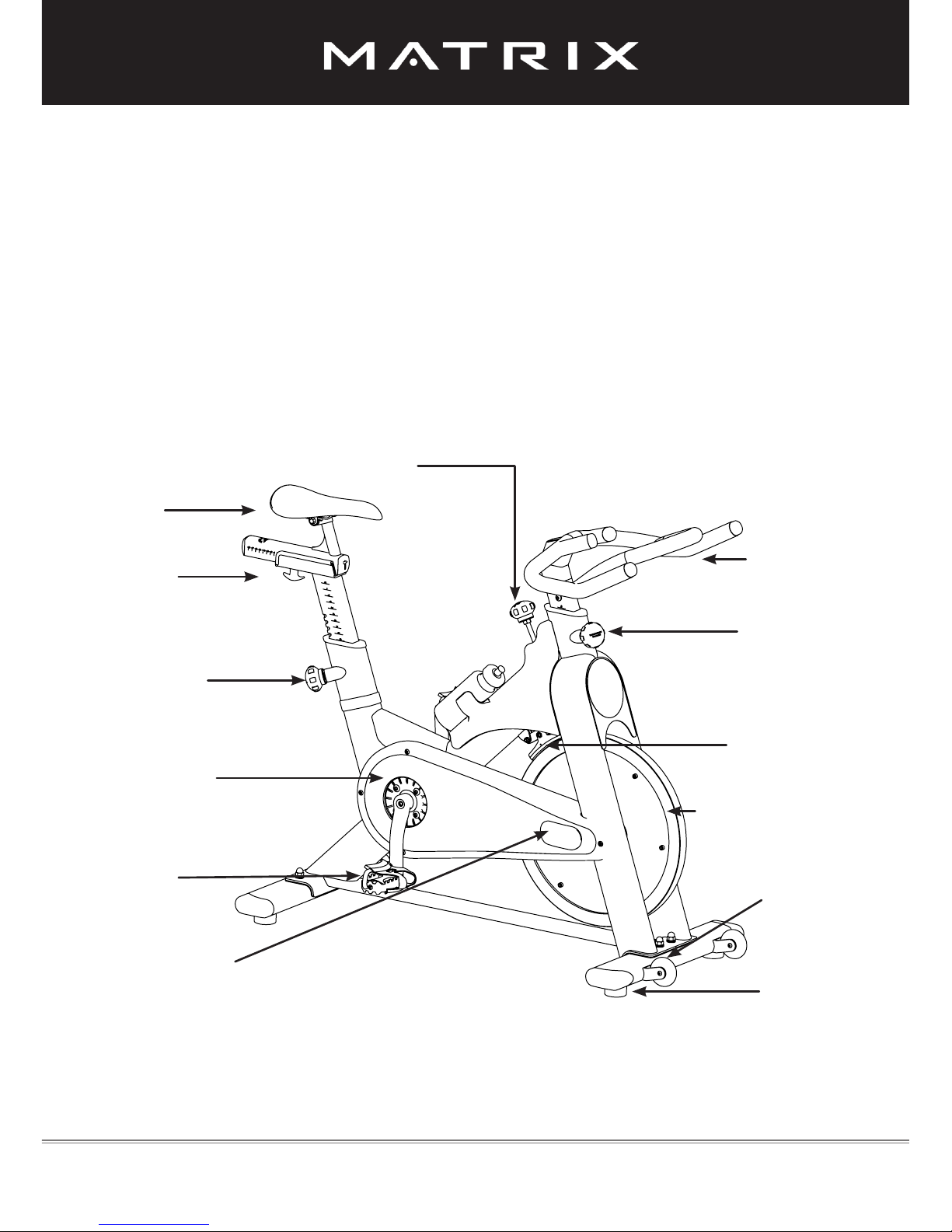
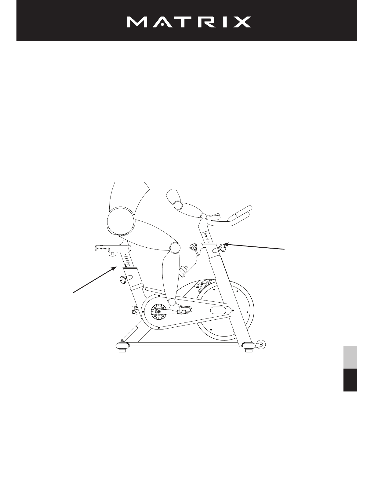
You will nd the production code on the left side of the Matrix E-Seriess within the lower
range of the frame. Please register to these in servicing and maintenance lists.
Emergency Brake & Resistance Knob
Saddle
T- Lock
Handle
Adjustment
Knob
Pedal /
Toe Clip
Chain Guard
Maintenance
Cover
Handlebar
Adjustment
Knob
Brake Pad
Flywheel
Transport
Wheel
Levelling
Feet
Dear customer,
Congratulations for selecting the Matrix E-Series. The Matrix indoor
cycle offers an impressive array of features designed to enhance cardiovascular tness,
tone muscles, and develop endurance. Whether users are beginners or experienced
athletes, the Matrix E-Series offers workouts that will help users to reach their individual
tness goals.
IMPORTANT: Read this manual carefully before assembling or using the indoorcycle.
If you have questions after reading this manual, please contact your local distributor or
refer to the website www.indoorcycling.com. Before reading further, please familiarize
yourself with the parts that are labeled in the drawing below.
Page 5
Version 1.0 2013 IC-MXEB-01 Copyright by Indoorcycling Group GmbH 2013 | www.indoorcycling.com ENG 5
1
3 4
2
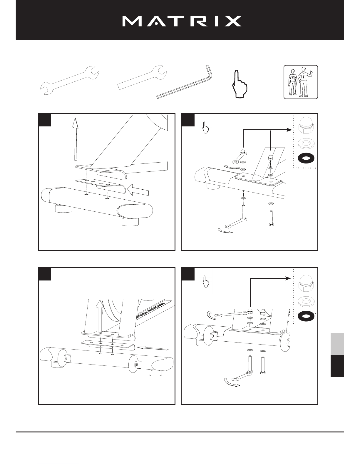
Assure that plastic gasket is placed between
stabilizer and frame.
Assure that plastic gasket is placed between
stabilizer and frame.
Assure that black rubber washer is placed
between upper frame and bolt/washer.
Assure that black rubber washer is placed
between upper frame and bolt/washer.
Please assure that nuts are tightened with signi cant strength to minimize loosening during use.
HOW TO ASSEMBLE Matrix E-Series
SW 17mm
SW 14mm
3mm
hand tight
2x
15mm Pedal
Wrench
1x
ENG ESP
Page 6
Version 1.0 2013 IC-MXEB-01 Copyright by Indoorcycling Group GmbH 2013 | www.indoorcycling.com ENG 6
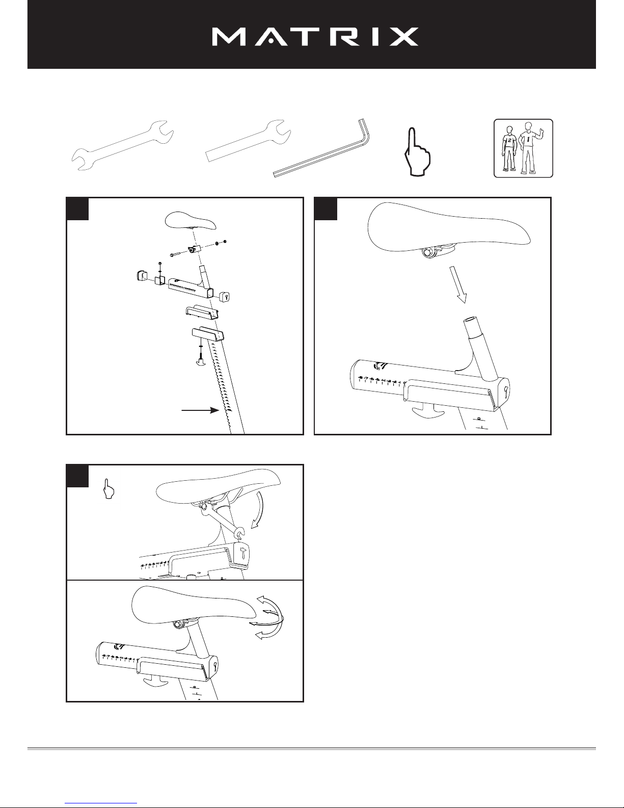
5 6
7
STOP mark
HOW TO ASSEMBLE Matrix E-Series
SW 17mm
SW 14mm
3mm
hand tight
2x
15mm Pedal
Wrench
1x
Make sure the seat is xed properly in
a LEVEL HORIZONTAL position and
securely tigthend from both sides!
Page 7
Version 1.0 2013 IC-MXEB-01 Copyright by Indoorcycling Group GmbH 2013 | www.indoorcycling.com ENG 7
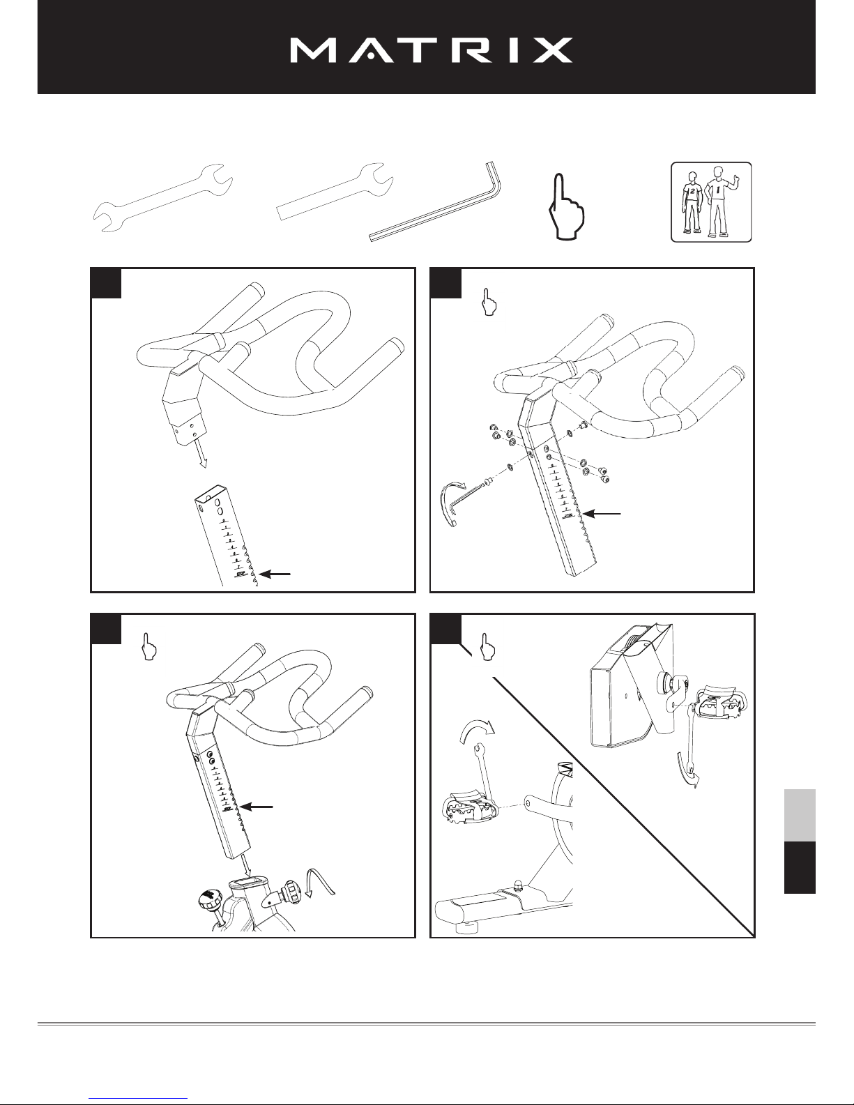
8 9
10 11
STOP mark
STOP mark
Stop mark
HOW TO ASSEMBLE Matrix E-Series
SW 17mm
SW 14mm
3mm
hand tight
2x
15mm Pedal
Wrench
1x
Pedal marked R installed on right crank (clockwise). Pedal marked L installed on left crank
(counter-clockwise) Pedals must be fastened with signi cant strength to avoid loosening
with use of the Matrix E-Series.
ENG ESP
Page 8

The cycle tune-up must be performed at initial installation of the Matrix E-Series for optimal performance and
longevity. Please read and follow all instructions below. If the Matrix E-Series is not installed and tuned as
described, components may wear excessively and the Matrix E-Series may become damaged. If you have
questions about the installation, please contact service@indoorcycling.com.
Note: Some maintenance procedures require acid-, silicone- and solvent free spray lubricant (for example BRUNOX), and White Lithium grease.
1. Make sure that the Matrix E-Series is level. If the Matrix E-Series rocks on the oor,
turn the leveling feet underneath the front and/or rear stabilizer until the rocking motion is elimina
ted.
2. Verify Emergency brake function to assure that emergency brake functions correctly.
3. Brake pad calibration: Turn resistance knob counterclockwise as far as possible (minimum bra king effect), verify that there is a slight separation of the brake pad from ywheel. Brake pad should
barely touch the ywheel when resistance knob is turned counter-clockwise as far as it can go.
4. Apply spray lubricant to the brake pad using the lubrication holes on the plastic part or the brake
pad and externally on the felt pad. Make sure brake pad is thoroughly soaked from end to end with
lubricant spray. Then, wipe the excess off from the ywheel.
* Best Practice: Use a rellable spray bottle lled with non-aerosol acid-, silicone- and solvent
free spray lubricant purchased by the gallon (3.7 L) at the local hardware store.
5. Apply Lithium grease to the threads on the lower end of the brake rod. First, turn the Resistance
knob clockwise until it stops. Apply a small amount of white lithium grease to the threads on the
brake rod above the two lock nuts. Then, turn the resistance knob counter-clockwise until it stops.
6. Apply Lithium grease on the metal threads of all the adjustment knobs.
7. Verify four (4) Allen nuts on RS pulley for tightness. If loose, apply LocTite Threadlocker Blue-242
and retighten.
8. Verify R and L crank arm Allen bolts for tightness. If loose, apply LocTite Threadlocker Blue-242 and
retighten.
9. Verify belt tension. Check if belt drive is rmly tightened and does not slip while riding under resis tance load. In case that the belt slips, proceed using the adjustment technique as described on
page (17). Please note that a belt drive gear never shows slack. In case of adjustment do
not apply too much tension.
10. Wipe down bike frame with rag moistened with solvent free spray lubricant
11. Some parts of the Matrix E-Series may become loose during shipment. Check crank arms,
check all exposed screws, bolts, and nuts, and make sure that they are properly tightened.
Customer Service
1. Provide basic maintenance instructions to client and direct them to detailed maintenance instruc tions (page 13-19 )
2. Sign-off sheet provided to client to conrm explanation of maintenance procedures/manual and
verication of condition of bikes?
Version 1.0 2013 IC-MXEB-01 Copyright by Indoorcycling Group GmbH 2013 | www.indoorcycling.com ENG 8
INITIAL INSTALL CHECKS
Page 9
HOW TO ADJUST THE Matrix E-Series
The Matrix E-Series can be adjusted for maximum comfort and exercise effectiveness. The
instructions below describe one approach to adjusting the Matrix E-Series to ensure optimal user comfort and ideal body positioning; you may choose to adjust the Matrix E-Serie
cycle differently.
Pedal strap adjustment:
Sit on the saddle and position your feet on the pedals, with the balls of your feet
directly above the spindles of the pedals (see the drawing below). Adjust the pedal
straps so the toe clips (cages) are snug but not too tight. Note: In the case of a Bike
being tted with Combi-pedals, the pedals feature toe clips on one surface and SPD
cleats on the opposite surface. If desired, use the shoe cleats with cycling shoes
instead of the toe clips.
Saddle height adjustment:
Sit on the saddle and slowly pedal until the right pedal is in the lowest position. Your knees
should be slightly bent without a dropping of the hips.
To avoid hyper extending your knees, make sure that your legs are not completely
straight.
Please do not adjust
handlebar height beyond
the STOP mark on the stem
and ensure the pop pin is
fully engaged and securely
tightened (see page 7).
Please do not adjust saddle
height beyond the STOP
mark on the stem
and ensure the pop pin is
fully engaged and securely
tightened (see page 6).
Please avoid overtightening the pop pin adjustment knob as this may cause damages to the vertical aluminum stems.
ENG ESP
Version 1.0 2013 IC-MXEB-01 Copyright by Indoorcycling Group GmbH 2013 | www.indoorcycling.com ENG 9
Page 10
Version 1.0 2013 IC-MXEB-01 Copyright by Indoorcycling Group GmbH 2013 | www.indoorcycling.com ENG 10
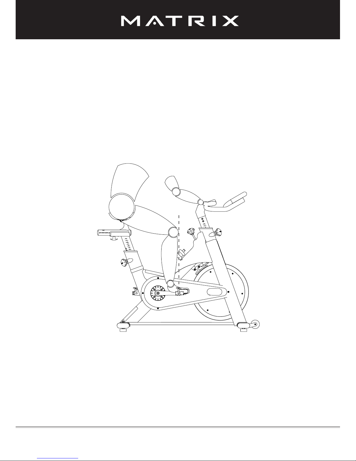
Saddle horizontal adjustment:
Proper horizontal adjustment of the saddle is very important in avoiding injury to the knees.
Sit on the saddle and move the pedals until the crank arms are in horizontal position.
Using your forward most leg as a marker, your kneecap should be directly above the
center of the pedal so that a straight line is created between knee and center of the
pedal (see the dotted line in image below). To adjust the horizontal position of the
saddle, rst dismount the Matrix E-Series. Next, loosen the rear adjustment knob, slide
the saddle forward or backward as required, and then retighten the knob.
HOW TO ADJUST THE Matrix E-Series
Page 11

If your Matrix E-Series is equipped with a regular 2 way handlebar. If the handlebar is too close to the saddle, your breathing may feel restricted;if the handlebar is too far from the saddle,
you may experience back discomfort. To adjust the horizontal position to the handlebar, rst
dismount the Matrix E-Series. Check for proper handlebar position by positioning your elbow
so that it is touching the front tip of the saddle at a 90 degree angle and checking that the ngertip of your middle nger is touching the handlebar at the mid-point. If it is not as described
then loosen the fore-aft T-lock handle and slide the saddle slightly forward or backward until
your middle nger is touching the handlebar at the mid-point, and then retighten the handle.
Changing your hand position can change the angle of your back, neck, and arms. To minimize the stress on your muscles during your workouts, change your hand position frequently.
A
B
Version 1.0 2013 IC-MXEB-01 Copyright by Indoorcycling Group GmbH 2013 | www.indoorcycling.com ENG 11
Handlebar adjustment:
Begin with the top of the handlebar at relatively the same height or just slightly higher than
the top of the saddle (dotted horizontal line A in the drawing above) and at a neutral
fore/aft position (see dotted vertical line B in drawing above). If your knees touch the
handlebars or if you experience back discomfort while pedalling for extended periods of
time, the height of the handlebars can be adjusted. First, dismount the Matrix E-Series.
Next, turn the front adjustment knob counter clockwise, slide the handlebar post up or
down, and then retighten the adjustment knob.
HOW TO ADJUST THE Matrix E-Series
ENG ESP
Page 12
HOW TO OPERATE THE Matrix E-Series
!
!
Red Resistance knob (turn)
Emergency brake (push)
levelling feet
Version 1.0 2013 IC-MXEB-01 Copyright by Indoorcycling Group GmbH 2013 | www.indoorcycling.com ENG 12
Resistance adjustment:
The preferred level of difculty in pedalling (resistance) can be regulated in ne increments
by use of the resistance knob. To increase the resistance, turn the resistance knob
clockwise. To decrease the resistance, turn the knob counter clockwise.
IMPORTANT: To stop the ywheel (wheel) while pedalling, push down on the red brake
knob. The ywheel should quickly come to a complete stop. Please make sure your shoes
are xed into the toe clip or in case cycling shoes are used your shoe cleat is connected
to the pedal binding while riding.
The Matrix E-Series does not have a free moving ywheel (wheel); the pedals
will continue to move together with the ywheel until the ywheel stops. Reducing speed in a controlled manner is required. To stop the ywheel immediately, push down the red break knob. Always pedal in a controlled manner
and adjust your desired cadence according to your own abilities. Push the
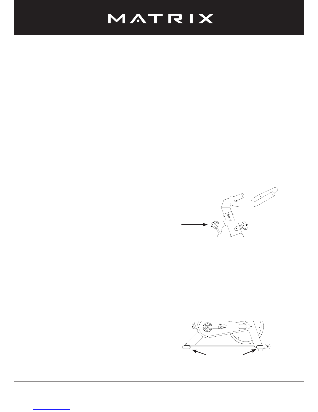
red knob down = emergency Stop
If the Matrix E-Series rocks on the oor after
being set down, turn the levelling feet (see
diagram) underneath the front or rear stabilizer until the rocking motion is eliminated.
Important: Please do not unscrew the levelling feet more then ½ inch!
How to move the Matrix E-Series:
Due to the weight of the Matrix E-Series, it is recommended that two persons move it. While
one person lifts the back of the Matrix E-Series, the second person rmly holds the handlebarand tips the Matrix E-Series forward until it rolls on the wheels. Carefully move the
indoor studio cycle to the desired location and then lower it. CAUTION: To reduce the risk
of injury, use extreme caution while moving the indoor studio cycle. Do not attempt
to move it over uneven surfaces and make sure a safety space of min 20 inch to the
nearest equipment is redeemed.
Page 13
2
PREVENTATIVE MAINTENANCE
Version 1.0 2013 IC-MXEB-01 Copyright by Indoorcycling Group GmbH 2013 | www.indoorcycling.com ENG 13
Regular maintenance must be performed on the Matrix E-Series for optimal
performance and longevity. Please read and follow all instructions below. If the
Matrix E-Series is not maintained as described, components may wear excessively
and the Matrix E-Series may become damaged. Improper maintenance will void the
warranty terms. If you have questions about maintenance, contact your local
distributor or refer to www.indoorcycling.com
Note: Many maintenance procedures require lubricant spray. Manufacturer
recommends for example Brunox or a similar solvent- and acid free lubricant.
Daily maintenance:
1. Make sure that the Matrix E-Series is level. If the Matrix E-Series rocks on your oor, turn
the levelling feet underneath the front or rear stabilizer until the rocking motion is eliminated
(see HOW TO MOVE THE Matrix E-Series on page 12).
2. After each user nishes exercising, the Matrix E-Series should be disinfected and cleaned to maintain a hygienic environment. First, apply a disinfectant spray to the handlebars
and the saddle. Using a lint-free cloth, dry the handlebars and the saddle. Next, apply a
small amount of disinfectant to a lint-free cloth and clean the adjustment knobs and the
adjustment handles. Avoid using strong detergents on the Matrix E-Series frame.
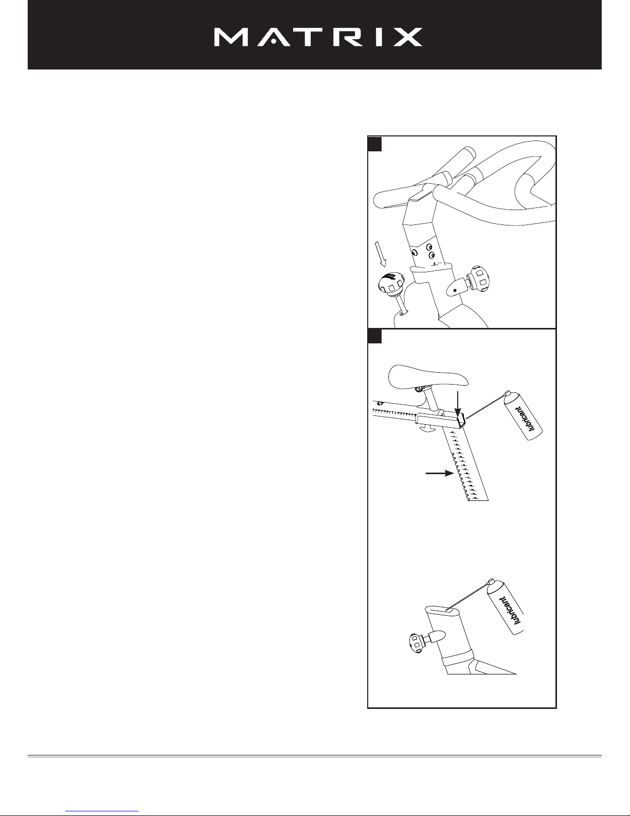
Weekly maintenance:
1. Apply a small amount of the lubrication spray to a lint-free cloth, and thoroughly clean
the frame, the handlebar slider and seat sliders the ywheel and the plastic parts of the
Matrix E-Series.
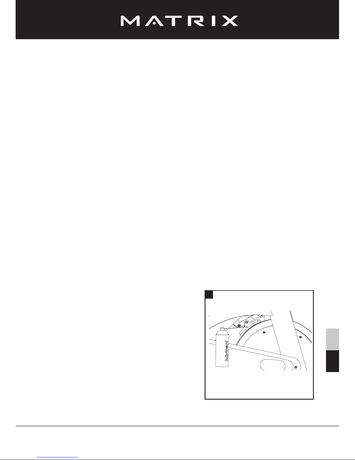
2. For optimal performance of the resistance
system, and to minimize wear on the brake pad,
the
acid-, silicone- and solvent free spray lubricant
should be applied to the brake pad using the lubrication holes on the plastic part of the brake pad. If
fuzz or lint appears on the brake pad, the brake pad
has become too dry-lubricant spray should be applied more frequently. Make sure brake pad is thoroughly soaked from end to end with lubricant spray.
Then, wipe the excess off.
ENG ESP
Page 14
1
2
A
B
Version 1.0 2013 IC-MXEB-01 Copyright by Indoorcycling Group GmbH 2013 | www.indoorcycling.com ENG 14
Bi-weekly maintenance:
1. The Matrix E-Series should not be used if the
emergency brake system is not working properly.
While sitting on the saddle and pedalling, test the
brake by pushing down the brake knob. The
ywheel should come to a quick and complete
stop.
2. To maintain the easy adjustability of the saddle
post, the saddle post should be cleaned and
lubricated. Turn the rear adjustment knob counter
clockwise and slide the saddle post out of the
frame. Apply a small amount of lubricant spray to a
lint-free cloth, and clean the saddle post (A). Next,
apply a small amount of lubricant spray inside of
the rear frame sleeve. Then, reinsert the saddle
post into the frame and adjust it to the desired
height.
Next, loosen the rear lock handle and slide
the saddle carriage as far backward as possible.
Apply a small amount of lubricant spray to a
lint-free cloth, and clean the top of the saddle slide
(B). Then, slide the saddle carriage as far forward
as possible and clean the top of the saddle slide.
Finally, adjust the saddle to the desired position.
PREVENTATIVE MAINTENANCE
Page 15
3
1
A
Version 1.0 2013 IC-MXEB-01 Copyright by Indoorcycling Group GmbH 2013 | www.indoorcycling.com ENG 15
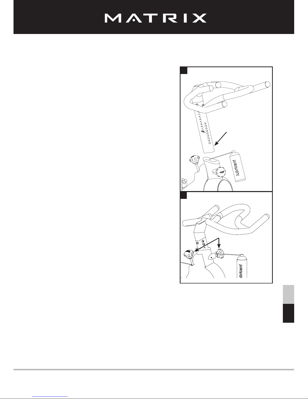
3. To maintain the easy adjustability of the
handlebar post, the handlebar post should be
cleaned and lubricated. First, turn the front adjustment knob counter clockwise and slide the
handlebar post out of the frame. Apply a small
amount of lubricant spray to a lint-free cloth, and
clean the handlebar post (C). Next, apply a small
amount of lubricant spray inside of the front frame
sleeve.
Then, reinsert the handlebar post into the frame
and adjust it to the desired height.
Monthly maintenance:
1. To maintain the smooth function of the adjustment knobs controlling the handlebar and saddle,
the metal threads on the adjustment knobs (A)
must be lubricated.
C
PREVENTATIVE MAINTENANCE
ENG ESP
Page 16
Version 1.0 2013 IC-MXEB-01 Copyright by Indoorcycling Group GmbH 2013 | www.indoorcycling.com ENG 16
4
C
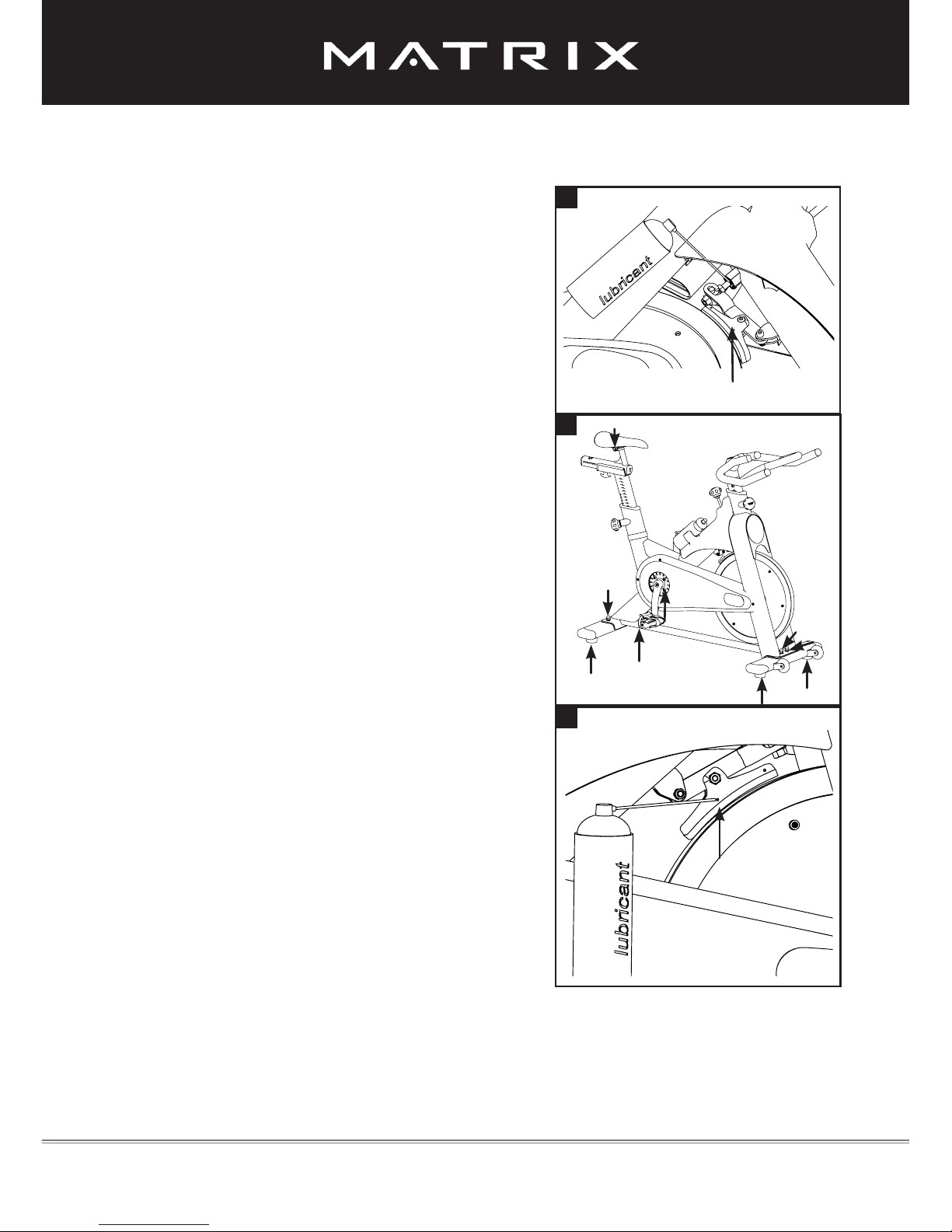
3. Some parts of the Matrix E-Series may become
loose as a result of repeated use. Check pedals, toe
clips, and pedal straps, and make sure that
they are properly tightened. Next, check all exposed
screws, bolts, and nuts, and make sure that they
are properly tightened. Finally, check the saddle to
make sure that it is not lose damaged.
4. The brake pad will become worn as a result of
repeated use. The Matrix E-Series should not be
used if the emergency braking system is not working properly (see page 12)! Should you feel that
the resistance system’s functions are decient, it is
essential to ne-tune the resistance system before
the bike is used again! Please check the setting of
the brake system as follows: First turn the resistance regulator on the brake system as far as
it will go to the left (minimum braking effect). If the
setting is correct, the brake pads should be ush
with the ywheel and barely touching so that it’s
possible to cycle with a hardly noticeable amount
of resistance. The brake pad can be adjusted using
a 10 mm wrench. Next, check the brake pad for
signs of wear. If the brake pad does show signs of
excessive wear, thoroughly soak the brake pad
with lubricant spray using the 2 lubrication holes
(C), and then wipe the excess off.
2
B
2. To maintain the easy adjustability of the
resistance system, the screw threads on the lower
end of the brake rod should be lubricated. First,
turn the resistance knob clockwise until it stops.
Next, look under the right or left side of the frame
and locate the brake rod (B). Apply a small amount
of synthetic grease (white lithium grease) to the
thread on the brake rod. Then, turn the resistance
knob counter-clockwise until it stops.
PREVENTATIVE MAINTENANCE
3
Page 17
Version 1.0 2013 IC-MXEB-01 Copyright by Indoorcycling Group GmbH 2013 | www.indoorcycling.com ENG 17
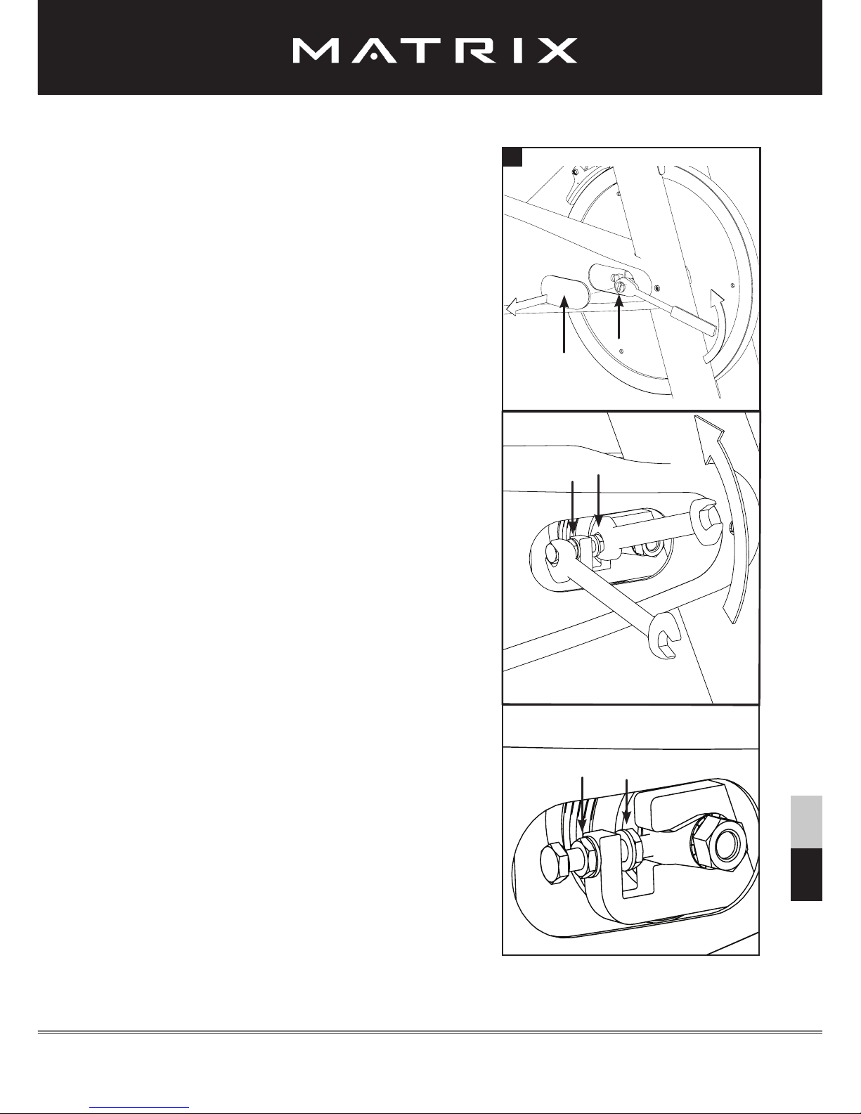
Finally, retighten the two outer lock nuts (C) to
secure the new adjustment and retigthen the two
axle nuts (B). At last reattach the maintenance covers (A).
Check if belt drive is rmly tighten and does not slip
while riding under resistance load. In case that the
belt slips, proceed using the same technique as
described above. Please note that a belt drive gear
never shows slack. In case of adjustment do not
apply too much tension.
The manufacturer recommends using an ultrasonic
voltage meter adhering to a natural frequency of
the belt of 103 Hz ± 3 Hz. Ball bearing damage
due to incorrect belt tension is excluded from
warranty.
Graphics are the right side
of the Bike (riding position)
5. Belt drive
Important: A loose belt as well as an overtightened
belt may cause injury of the rider or damage to the
drive system. Checking belt tension: To check for
a loose belt, sit on the saddle, place your feet on
the pedals, move the pedals until the crank arms
are horizontal. Next, pull up the emergency brake
handle and hold it. Then, stand on the pedals and
rock forward and backward. There should be no
play or slip in the drive train. If there is slip or play
in the drive train, this indicates that the belt is too
loose.
Correct a slipping belt drive train: To adjust the
belt, pull off the right and the left maintenance
covers (A). Loosen the axle nut (B) on both ends of
the ywheel axle by two full turns. Loosen the inner
adjustment nut (D) facing the ywheel axle on each
side of the ywheel. Next, losen the lock nut (C).
Then, turn both (right and left sides) of the inner
adjustment nuts (D) on the intside of the ywheel
bracket ¼ of a turn at a time (upward on the R side
and downward on L side) until the belt is properly
adjusted. Make sure to turn both adjustment nuts
exactly the same amount to avoid misalignment of
the ywheel. Re-check if the amount of play or slip
in the drive train has disappeared.
A
B
C
4
D
D
C
PREVENTATIVE MAINTENANCE
ENG ESP
Page 18

MAINTENANCE ACTIVITY AND REQUIRED SCHEDULE
Activity Rotation Details found on
Examples of maintenance Plan charts for in house service technicians:
Weekly maintenance Checklist
Bike No. Production code Observations Action taken Result Name / date
Feet levelling, disinfection and cleaning of the bike daily page 13
Servicing brake pads, detailed cleaning of the entire bike weekly page 13
Check emergency brake function bi-weekly page 14+15
Clean and lubricate saddle and handlebar sliders / posts bi-weekly page 14+15
Check adjustment knobs monthly page 15
Check brake pad for signs of wear monthly page 16
Check brake system, lubricate monthly page 16
Check pedals, toe clip and straps for signs of wear monthly page 16
Check all connections and xings if they are secure and correctly tightened monthly page 16
Check belt drive train monthly page 17
Version 1.0 2013 IC-MXEB-01 Copyright by Indoorcycling Group GmbH 2013 | www.indoorcycling.com ENG 18
Page 19

Monthly maintenance Checklist
Bike No. Production code Observations Action Taken Result Name / date
Bi-Weekly maintenance Checklist
Bike No. Production code Observations Action Taken Result Name / date
Version 1.0 2013 IC-MXEB-01 Copyright by Indoorcycling Group GmbH 2013 | www.indoorcycling.com ENG 19
MAINTENANCE ACTIVITY AND REQUIRED SCHEDULE
ENG ESP
Page 20

SPARE PARTS
Brake Parts
02 50 A
02 50 06
02 50 04
02 50 03 A
02 50 05
Version 1.0 2013 IC-MXEB-01 Copyright by Indoorcycling Group GmbH 2013 | www.indoorcycling.com ENG 20
02 40 C S 08
02 40 CRMO R E 08
02 40 90
02 40 BE
02 40 C MD20 08
02 40 CRMO L E 08
02 40 C 2RS
Drive Gear Parts
02 40 BPG
Page 21

Version 1.0 2013 IC-MXEB-01 Copyright by Indoorcycling Group GmbH 2013 | www.indoorcycling.com ENG 21
Handlebar
02 30 01 AL
Flywheel
02 40 H L
02 40 02
02 40 08 E 12
02 40 H
SPARE PARTS
02 40 BPK
ENG ESP
Page 22

Frame
02 10 A
2004 RA E
Version 1.0 2013 IC-MXEB-01 Copyright by Indoorcycling Group GmbH 2013 | www.indoorcycling.com ENG 22
02 42 01 E 08
02 42 03 S E 12
02 99 03
02 42 02 E 12
02 42 04
Chain Guard
02 99 02
02 10 A
02 99 11
(optional)
02 99 10
(optional)
SPARE PARTS
sticker set complete 02 99 50 E MX 12
Page 23

Version 1.0 2013 IC-MXEB-01 Copyright by Indoorcycling Group GmbH 2013 | www.indoorcycling.com ENG 23
Pop pin adjustment knobs
02 99 02 10 HB
(optional item)
02 10 B 08
SPARE PARTS
ENG ESP
Page 24

Version 1.0 2013 IC-MXEB-01 Copyright by Indoorcycling Group GmbH 2013 | www.indoorcycling.com ENG 24
Saddle Support
0121VL-3125 SW
02 21 AK
02 21 01 AL
(complete asembly)
02 10 G
Pedals
01 40 A 2 (pair)
02 20 02
SPARE PARTS
01 40 A 3 (pair)
Page 25

Version 1.0 2013 IC-MXEB-01 Copyright by Indoorcycling Group GmbH 2013 | www.indoorcycling.com ENG 25
Rear Stabilizer
02 11 05 B
Front Stabilizer
02 11 E
02 11 02 E 08
02 11 06
02 11 B
02 11 A
02 11 01 E 08
SPARE PARTS
ENG ESP
Page 26

Version 1.0 2013 IC-MXEB-01 Copyright by Indoorcycling Group GmbH 2013 | www.indoorcycling.com ENG 26
SPARE PARTS LIST
Drive Gear Parts
02 40 CrMo R E 08 Right crank
02 40 CrMo L E 08 Left crank
02 40 C S 08 Allen bolt M8x20
02 40 C MD20 08 BB assembly MD20
02 40 C 2 RS Ball bearing SKF 6004Z
Brake Parts
02 50 A Brake adjustment knob
02 50 06 Bell crank
02 50 04 Brake pad
02 50 03 A Upper brake rod
02 50 05 Lower brake rod
Flywheel
02 40 H Flywheel axle
02 40 02 Chain tensioner
02 40 H L Flywheel bearing 6001Z
02 40 08 E 12 E-Series ywheel
Chain Guard
02 42 02 E 12 Outer chain guard
02 42 04 Plastic cover
02 42 01 E 08 Inner chain guard
02 42 03 S E 12 Left cover
02 99 03 Allen bolt M4x15
Pedals
01 40 A 2 Combi-Pedals (pair)
01 40 A 3 toe strap (pair)
Frame
2004 RA E E-Series frame
02 10 A Vertical insert sleeve
02 20 04 Rubber stop handleb.tube
02 99 02 Bottle holder
02 99 50 E MX 12 Sticker set complete
Belt drive
02 40 BE Belt
Handlebar
02 30 01 AL E-Series handlebar
02 10 B 08 Pop pin adjustment knob
Saddle Support
0121VL-3125 SW Saddle
02 21 AK Saddle mounting bracket
02 21 01 AL Horizontal & vertical
saddle support
02 20 02 Horizontal insert sleeve
02 10 G T- Lock handle
02 10 B 08 Pop pin adjustment knob
Rear Stabilizer
02 11 E PVC gasket
02 11 02 E 08 Rear stabilizer
02 11 06 Plastic end cover
02 11 05 B Rubber foot stand
02 99 11 Rear protection plates
(optional)
Front Stabilizer
02 11 01 E 08 Front Stabilizer
02 11 B Stabilizer mounting kit
02 99 10 Front protection plates
02 11 A Transport wheel
Page 27

Version 1.0 2013 IC-MXEB-01 Copyright by Indoorcycling Group GmbH 2013 | www.indoorcycling.com ENG 27
LIMITED WARRANTY Matrix E-Series
Matrix Fitness System Corp. warrants that all new equipment will be free of manufacturing
defects in workmanship and materials, becoming effective on the date of original
installation. Parts repaired or replaced under the terms of this warranty will be warranted
for the remainder of the original warranty period only. Warranty may vary by region or
country. Please contact www.matrix tness.com.
WARRANTY TERMS
Defects caused by inappropriate use or handling of the product may cause denegation of the manufacturers warranty
10 years warranty: Frame construction and welding
3 years warranty : Handlebar and saddle assembly, brake system (excluding
brake pad), lever handles and knobs, cranks, belt drive
system, bottom bracket assembly, ywheel and hub assembly,
powder coating of frame parts.
2 years warranty : Pedals, insert sleeves for handle bar and saddle post,
leveling feet.
1 years warranty: Saddle construction
The following wear items are excluded from warranty:
Pedal straps, pedal binding system, water bottle holder.
ENG ESP
Page 28

Page 29

Version 1.0 2013 IC-MXEB-01 Copyright by Indoorcycling Group GmbH 2013 | www.indoorcycling.com ESP 1
Matrix E-Series
modelo N°:
IC-MXEB-01
Fabricante:
Indoorcycling Group GmbH
Happurger Str. 86
90482 Nuremberg | Germany
www.indoorcycling.com
info@indoorcycling.com
MATRIX Fitness Systems Corp.
1610 Landmark Drive
Cottage Grove, WI 53527
Libre: 866.693.4863
Local: 608.839.8686
www.matrix tness.com
Nota Importante:
Lea todas las instrucciones y precauciones en este manual antes de la puesta en servicio
de la bicicleta y observe todas las instrucciones descritas para el montaje, mantenimiento y
funcionamiento de la bicicleta.
¡El uso y manejo inapropiado, montaje incorrecto y la falta de mantenimiento pueden
derivar en la cancelación de la garantía!
ESP
ENG
Page 30

Version 1.0 2013 IC-MXEB-01 Copyright by Indoorcycling Group GmbH 2013 | www.indoorcycling.com ESP 2
ÍNDICE
PÁGINA
Advertencias importantes de seguridad 3
Introducción 4
Montaje de la bicicleta Indoor Matrix E-Series 5-7
Comprobaciones iniciales de montaje 8
Ajuste correcto de la bicicleta Indoor Matrix E-Series 9-11
Regulación y ajuste del freno 12
Estabilidad de la bicicleta Indoor Matrix E-Series 12
Mantenimiento preventivo 13
Mantenimiento diario 13
Mantenimiento semanal 13
Mantenimiento cada dos semanas 14
Mantenimiento mensual 15-16
Accionamiento por correa 17
Plan de mantenimiento y lista de revisiones 18-19
Dibujos de los componentes y módulos 20-25
Lista de piezas de recambio 26
Garantía 27
Datos técnicos:
La bicicleta Indoor Matrix E-Series corresponde, conforme a EN 957, a la clase de usuario
E y está clasicada para el uso en un entorno controlado, como por ejemplo en centros
deportivos y gimnasios bajo la dirección de un entrenador o instructor.
Peso de la bicicleta: 50 kg / 110 lbs
Peso máximo del usuario: 130 kg / 287 lbs
Supercie de apoyo requerida: 55 x 115 cm / 21.6 x 45.3 inch
Altura máxima del manillar: 115 cm / 45.3 inch
Altura máxima del sillín: 115 cm / 45.3 inch
La bicicleta está diseñada para acomodarse a usuarios de una talla de entre 150 a 205
cm / 59.1 a 81.7 inch
Page 31

ADVERTENCIAS IMPORTANTES
ADVERTENCIA
Para reducir el riesgo de lesiones por manejo inadecuado de la bicicleta, por favor lea atentamente y
observe las siguientes advertencias e informaciones de seguridad antes de empezar a usar la bicicleta Indoor Matrix E-Series.
El propietario es el único responsable de asegurar que todos los usuarios de la bicicleta Indoor
Matrix E-Series hayan sido informados sobre cada una de las precauciones y advertencias de
seguridad para un uso adecuado y responsable de la bicicleta.
El montaje y la comprobación de la bicicleta Indoor Matrix E-Series sólo ha de ser llevado a cabo
como se describe en este manual.
No utilice la bicicleta Indoor Matrix E-Series hasta que haya sido montada correctamente (pág.5-
7).
Mantenga la bicicleta Indoor Matrix E-Series alejada de humedad y polvo. No almacene la bicicleta
Indoor Matrix E-Series en un garage, terraza cubierta o cerca de lugares con agua y humedades.
Sitúe la bicicleta Indoor Matrix E-Series sobre una super cie plana y nivelada. Coloque una alfombrilla antideslizante entre el suelo y la bicicleta para evitar daños en el suelo. Asegúrese que
haya su ciente espacio alrededor de la bicicleta para montar, desmontar y pedalear sin peligro.
Inspeccione y apriete todas los componentes de la bicicleta Indoor Matrix E-Series periodicamente
tal y como se describe en este manual. Por favor reemplace las piezas defectuosas inmediatamente y no utilice la bicicleta hasta que la reparación haya concluido. Utilice solamente piezas
originales del fabricante.
Los jóvenes menores de 14 años sólo deben utilizar la bicicleta Indoor Matrix E-Sereis previo consentimiento paterno y ser supervisados por un instructor o entrenador cuali cado.
La bicicleta Indoor Matrix E-Series, no debe ser utilizada por personas con un peso superior a
130Kg.
Utilice siempre ropa y calzado de deporte o de ciclismo adecuado mientras utiliza la bicicleta Indoor Matrix E-Series. No práctique ciclismo Indoor con ropas holgadas ni cordones de zapatillas
desatados para evitar posibles engances con las partes jas y móviles de la bicicleta.
Antes de utilizar la bicicleta Indoor Matrix E-Series, asegúrese de que está familiarizado con su
manejo. (pág.8/11).
Las bicicletas Indoor Matrix E-Series no disponen de un volante de inercia libre de movimiento.
Los pedales seguiran moviendose junto con el volante (rueda), hasta que este se detenga.
Ajuste la resistencia del volante de inercia para mantener un movimiento de pedaleo controlado.
Mantenga su espalda recta y no arqueada mientras utiliza la bicicleta Indoor Matrix E-Series.
Si sintiese dolor o mareos durante el ejercicio, detengase inmediatamente y descanse.
Utilice solamente piezas originales suministradas por el fabricante, cuando necesite recambios.
Nota Importante:
Antes de empezar un programa de ejercicio, consulte a su médico.Esto es especialmente importante para personas con más de 35 años o con personas con problemas preexistentes de salud.
Lea todas las instrucciones antes de su utilización. Un entrenamiento incorrecto o excesico puede
causar series lesiones. El fabricante no asume responsabilidad por daños personales ni materiales como consecuencia de un uso inapropiado de este producto.
1.
2.
3.
4.
5.
6.
7.
8.
9.
10.
11.
12.
13.
14.
15.
ESP
ENG
Version 1.0 2013 IC-MXEB-01 Copyright by Indoorcycling Group GmbH 2013 | www.indoorcycling.com ESP 3
Page 32

Version 1.0 2013 IC-MXEB-01 Copyright by Indoorcycling Group GmbH 2013 | www.indoorcycling.com ESP 4
Freno de emergencia y Botón de regulación de resistencia
Sillín
Palanca de
bloqueo en T
Botón de ajuste
Pedal Combi
Protector de
cadena
Cubierta de mantenimiento
Manillar
Botón de ajuste
Pastilla de freno
Volante de
inercia
Rueda de
transporte
Pie de apoyo
INTRODUCCIÓN
Estimado cliente:
En primer lugar queremos darles las gracias por su conanza y felicitaciones por la compra
de esta bicicleta Matrix E-Series. Con esta bicicleta Indoor Matrix E-Series Ud. ha adquirido
un producto de alta calidad desarrollado bajo los mayores avances técnicos y congurado
para el más alto rendimiento y abilidad.
IMPORTANTE: Lea atentamente este manual antes de montar o utilizar la
bicicleta Indoor.
Sin embargo, este alto nivel de abilidad solamente puede garantizarse mediante un servicio
y mantenimiento regular. El cumplimiento de las instrucciones contenidas en este manual
le asegurará un nivel de rendimiento máximo y una larga vida útil de la bicicleta Matrix ESeries con bajo mantenimiento y una continuidad de funcionamiento sin problemas durante
muchos años.
Importante:
El código de producción de la bicicleta Matrix E-Series se encuentra en la placa de características técnicas ubicada en la parte inferior del tubo del cuadro cerca de la biela
del pedal izquierdo. Por favor, registre este código de producción en las listas de servicio
y mantenimiento. En todas las cuestiones de garantía deberá indicar necesariamente el
código de producción.
Page 33

Version 1.0 2013 IC-MXEB-01 Copyright by Indoorcycling Group GmbH 2013 | www.indoorcycling.com ESP 5
1
3 4
2
MONTAJE DE LA BICICLETA INDOOR Matrix E-SERIES
SW 17mm
SW 14mm
3mm
Apretado
a mano
2x 1x
15mm
Llave del pedal
Asegúrese de que la junta de plástico esté colocada entre el estabilizador y el cuadro.
La arandela negra de plástico tiene que estar colocada entre la estructura del cuadro y la arandela de acero.
Asegúrese de que la junta de plástico esté colocada entre el estabilizador y el cuadro.
La arandela negra de plástico tiene que estar colocada entre la estructura del cuadro y la arandela de acero.
Importante:
Asegurarse de que todos los elementos de unión y conexión estén apretados fuertemente.
ESP
ENG
Page 34

Version 1.0 2013 IC-MXEB-01 Copyright by Indoorcycling Group GmbH 2013 | www.indoorcycling.com ESP 6
5 6
7
Marca STOP
MONTAJE DE LA BICICLETA INDOOR Matrix E-SERIES
SW 17mm
SW 14mm
3mm
Apretado
a mano
2x 1x
15mm
Llave de pedal
Importante:
¡Coloque el sillín A NIVEL en posición horizontal y apriete fuertemente
las tuercas de 13 mm de la abrazadera del sillín!
Page 35

Version 1.0 2013 IC-MXEB-01 Copyright by Indoorcycling Group GmbH 2013 | www.indoorcycling.com ESP 7
8 9
10 11
Marca STOP
Marca STOP
Marca STOP
15mm
Llave del pedal
SW 17mm
SW 14mm
3mm
Apretado a
mano
2x 1x
MONTAJE LA BICICLETA INDOOR Matrix E-SERIES
Importante:
El pedal derecho, marcado con la letra (R), ha de montarse en sentido horario en la biela derecha
(R). El pedal izquierdo, marcado con la letra (L), ha de montarse en sentido anti-horario en la biela
izquierda (L).
Los paedales han de ser apretados su cientemente para evitar que se suelten durante el uso de la
bicicleta Indoor Matrix E-Series.
ESP
ENG
Page 36

Version 1.0 2013 IC-MXEB-01 Copyright by Indoorcycling Group GmbH 2013 | www.indoorcycling.com ESP 8
COMPROBACIONES INICIALES DE MONTAJE
Los ajustes deben realizarse durante la instalación inicial de la bicicleta Indoor para garantizar un nivel de rendimiento
óptimo y una vida útil de larga duración. Por favor, lea y siga exactamente las siguientes instrucciones. Si las bicicletas
no se instalan y ajustan en la forma descrita, los componentes pueden estar expuestos a un desgaste excesivo y sufrir
daños. Para preguntas en relación a la instalación diríjase a: service@indoorcycling.com
Nota: Para algunos procedimientos de mantenimiento se requieren lubricantes. Como fabricante recomendamos el uso de un spray lubricante sin disolvente, silicona y ácidos (p. ej. Brunox) y grasa de litio blanca.
1. Por favor asegúrese de que la bicicleta Matrix E-Series esté nivelada. Si se balancea sobre el piso, corrija la nivelación e inclinación ajustando los pies de nivelación situados debajo del estabilizador delantero y trasero hasta
que el movimiento de balanceo quede eliminado. Cuide de que los pies de nivelación no estén desenroscados
más de 10mm.
2. Compruebe el funcionamiento correcto del freno de emergencia.
3. Calibración del sistema de frenos: Gire el botón regulador de resistencia en sentido anti-horario hasta el tope
(efecto mínimo de resistencia) y asegúrese de que haya una leve separación entre la zapata y el volante de
inercia. La zapata debe tocar muy levemente el volante de inercia cuando el botón regulador de resistencia esté
girado en sentido anti-horario hasta el tope.
4. Aplique abundante spray lubricante sobre la zapata de freno usando para ello los oricios de lubricación en la
pieza de plástico de la zapata y desde fuera sobre la almohadilla de eltro. Asegúrese de que la zapata está bien
empapada con spray lubricante. Luego limpie el excesode aceite del volante de inercia con un paño. Recomendamos que use una botella de rociado recargable y la llene con el lubricante sin aerosol y sin ácido para proteger
el medio ambiente.
5. Aplique grasa de litio sobre las roscas de metal en el extremo inferior del tirante de freno. Primero gire el botón
regulador de resistencia en sentido horario hasta que se pare. Aplique un poco de grasa de litio sobre las roscas
en el tirante de freno encima de las dos tuercas estriadas. Luego gire el botón regulador de tensión en sentido
antihorario hasta que se pare.
6. Aplique grasa de litio en las roscas de metal en todos los botones de ajuste.
7. Compruebe si las cuatro (4) llaves Allen están bien apretadas. Si están ojas, aplique pegamento especial para
roscas Loctite Threadlocker Blue-242 y vuelva a apretarlas.
8. Compruebe si las dos llaves Allen con las que están jadas las bielas (en el lado derecho e izquierdo de la caja
de pedalier), están bien apretadas. Si están ojas, aplique pegamento especial para roscas Loctite Threadlocker
Blue-242 en las roscas de los tornillos y vuelva a apretarlas.
9. Compruebe la tensión de la correa de transmisión. Verique si el accionamiento por correa está bien apretado
y si al andar bajo resistencia funciona sin patinar. Si patina debe seguir las instrucciones de ajuste indicadas en
la página 17.
10. Humedecer un paño con spray lubricante y limpiar el cuadro.
11. Algunas piezas de la bicicleta Matrix E-Series pueden soltarse durante el transporte. Compruebe las bielas, todos
los tornillos expuestos, pernos, tuercas y asegúrese de que estén correctamente apretados.
Servicio de atención al cliente
1. Entregue al cliente las instrucciones para el mantenimiento básico y haga referencia a las instrucciones de
mantenimiento detalladas (pág. 13-19).
2. Firme la hoja entregada al cliente como prueba de que se han explicado los procedimientos de mantenimiento y
entregado el Manual y que se ha hecho una vericación de la condición de la bicicleta.
Page 37

AJUSTE CORRECTO DE LA BICICLETA
Version 1.0 2013 IC-MXEB-01 Copyright by Indoorcycling Group GmbH 2013 | www.indoorcycling.com ESP 9
Nunca ajuste la altura vertical del manillar por encima de la marca STOP
(ver pág. 7)
Nunca ajuste la altura vertical del sillín por encima de
la marca STOP
(ver pág. 6)
La bicicleta Matrix E-Series puede ser ajustada de forma muy variable y adaptadarla a los requerimientos de los distintos grupos de usuarios para garantizar un óptimo confort y un máximo nivel de entrenamiento del ciclista. Las instrucciones de ajuste que se describen a continuación garantizan una postura ideal del cuerpo adaptándose totalmente a la sionomía del
usuario. El usuario tiene varias variantes para ajustar su posición de asiento personalizada.
Ajuste de los pedales:
Móntese en el sillín en posición de hacer ejercicio y mantenga la cadera recta. Coloque el
pie en el pedal más cercano al suelo, en el rastral del pedal y fíjelo bien, pero no demasiado fuerte. Asegúrese de que las bielas están en posición vertical como se muestra en la
ilustración. Nota: Si la bicicleta está equipada con un el sistema de pedales Combi con
sistema (SPD), podrá usar zapatillas de ciclista con sistema SPD con jaciones o zapatillas
normales de deporte usando los rastrales.
Precaución:
No apriete demasiado fuerte las cabezas de tornillo, Ud. puede dañar las piezas de aluminio de los tubos verticales del manillar y sillín.
Ajuste de la altura del sillín
Empiece a pedalear despacio hasta que el pedal llegue a la posición indicada en la ilustración. El soporte del sillín vertical tiene que estar ajustado de modo que las rodillas siempre
estén ligeramente exionadas y la cadera no ladeada.
Por favor, no realice el ejercicio con las rodillas estiradas y la cadera ladeada.
ESP
ENG
Page 38

Version 1.0 2013 IC-MXEB-01 Copyright by Indoorcycling Group GmbH 2013 | www.indoorcycling.com ESP 10
AJUSTE CORRECTO DE LA BICICLETA
Regulación horizontal del sillín:
La posición horizontal del sillín es muy importante para evitar lesiones en las articulaciones de las rodillas. Móntese en el sillín y mueva los pedales hasta que las bielas estén
en posición horizontal.
La rodilla de la pierna delantera exionada debe hallarse directamente encima del eje
del pedal, creando una línea perpendicular entre rodilla y centro del pedal (ver la línea
rayada en la ilustración de abajo). Para ajustar la posición horizontal del sillín, desmóntese primero de la bicicleta Matrix E-Series. Luego aoje la empuñadora de jación en
T, deslice la guía corredera del sillín hasta la posición deseada. Apretar rmemente la
empuñadora de jación en T.
Palanca de
bloqueo en T
Page 39

A
B
Version 1.0 2013 IC-MXEB-01 Copyright by Indoorcycling Group GmbH 2013 | www.indoorcycling.com ESP 11
AJUSTE CORRECTO DE LA BICICLETA
Ajuste del manillar:
Comience colocando la parte superior del manillar a la misma altura o ligeramente más alto
que la parte superior del sillín (línea horizontal A en el dibujo de abajo) y en posición longitudinal neutral (linea inclinada B en el dibujo de abajo). Si sus rodillas tocan el manillar o si
experimenta molestias en la espalda mientras pedalea durante largos períodos de tiempo,
la altura del manillar se deberá ajustar. Primero, desmonte de la bicicleta Matrix E-Series.
A continuación, gire la perilla de ajuste situada al frente en sentido anti-horario, deslice la
tija del manillar hacia arriba o hacia abajo, y luego vuelva a apretar el tornillo de ajuste.
La bicicleta Matrix E-Series esta equipada con un manillar regulable en 2 posiciones. Si el
manillar está demasiado cerca del sillín puede ser que Ud. se sienta restringido al respirar, y
si el manillar está demasiado lejos del sillín puede ser que le duela la espalda. Para ajustar
la posición horizontal del manillar, desmontese primero de la bicicleta Matrix E-Series. Para
comprobar si la posición del manillar es correcta, apoye el antebrazo acodado en el extremo delantero del sillín formando un ángulo de 90 grados y toque con la punta de su dedo
medio el punto central del manillar. Para ajustar el manillar a la posición correcta suelte la
palanca atrás/adelante hasta que su dedo medio toque el manillar en el punto central.
El manillar (multiposición) ofrece múltiples posiciones de apoyo y posibilidades de ajuste
que permiten al usuario entrenado encontrar fácilmente su posición idónea de asiento y de
apoyo de las manos. Durante sesiones de ejercicio más largas se recomienda cambiar en
intervalos regulares la posición de manos para evitar un esfuerzo unilateral y monótona de
músculos, ligamentos y articulaciones.
ESP
ENG
Page 40

Version 1.0 2013 IC-MXEB-01 Copyright by Indoorcycling Group GmbH 2013 | www.indoorcycling.com ESP 12
REGULACIÓN Y AJUSTE DEL FRENO
!
!
Por razones de seguridad se recomienda manejar la bicicleta siempre con movimiento controlados y adaptar la cadencia de pedaleo a las capacidades del ciclista.
Ajuste de la resistencia de freno:
Para un control de esfuerzo individualizado de su ejercicio, la bicicleta dispone de un botón
de regulación de resistencia que permite un microajuste. Para aumentar la resistencia de
freno, gire el botón de ajuste de freno en sentido horario y para disminuirla en sentido antihorario.
Importante:
Para detener el volante de inercia (rueda), mientras pedalea, empuje hacia abajo el pomo
rojo del freno. El volante de inercia deberá llegar a apararse completamente. Por favor,
asegúrese de que sus zapatos de ciclismo se jan en el clip automático o que sus zapatillas de deporte se jan en los rastrales mientras pedalea.
La bicicleta Matrix E-Series no dispone de sistema de volante de inercia libre. Los
pedales continuarán moviéndose junto con el volante de inercia hasta que la rueda se
pare por completo. Por favor reduzca la velocidad de forma controlada. Para detener
de inmediato la rueda de inercia, presione el pomo rojo del freno hacia abajo.
Freno de emergencia = apretar el pomo rojo del freno.
Pomo regulador de resistencia (girar)
Pomo rojo de freno (apretar)
Cómo mover la bicicleta Matrix E-Series:
Debido al peso que tiene la bicicleta se recomienda que sea movida por 2 personas. Para
prevenir accidentes y daños es necesario que el ajuste vertical del manillar sea jado antes
de mover la bicicleta. Mientras una persona eleva la parte trasera de la bicicleta, la segunda persona sostiene jamente el manillar e inclina ligeramente la bicicleta hacia adelante
hasta que ruede sobre las ruedas de transporte. Mueva con cuidado la bicicleta y préste
especial atención ante posibles irregularidades del suelo para que la bicicleta no se incline
hacia un lado. Mantenga una distancia mínima de 50 cm. con otros equipos.
Compruebe el equilibrado perfecto de la bicicleta
Matrix E-Series en su nuevo lugar de empleo y, de
ser necesario, ajuste los pies regulables en altura
ubicados en la parte inferior de los estabilizadores
para garantizar la correcta estabilidad. Importante:
¡A ser posible, mantenga los pies de nivelación enroscados. Por favor no los desenrosque más de 1 cm!
Pies de
nivelación
Page 41

2
Version 1.0 2013 IC-MXEB-01 Copyright by Indoorcycling Group GmbH 2013 | www.indoorcycling.com ESP 13
MANTENIMIENTO PREVENTIVO
Para conseguir las mejores prestaciones y funcionamiento de la bicicleta, deberá leer detenidamente y cumplir las siguientes instrucciones de manejo, cuidado y mantenimiento
para aumentar la vida útil de la bicicleta Matrix E-Series y mantenerla en condiciones
apropiadas. ¡Los trabajos de cuidado y mantenimiento no realizados en los intervalos periódicos aconsejados producen un desgaste extra en los componentes y pueden causar la
cancelación de la garantía! Si tiene preguntas sobre este tema, en cualquier caso no dude
en ponerse en contacto con su distribuidor local o bajo www.indoorcycling.com.
Nota: Utilice únicamente productos de limpieza y cuidado sin agentes agresivos ni
disolventes. Los fabricantes recomiendan por ejemplo Brunox o cualquier otro lubricante sin disolvente, silicona y ácidos.
Mantenimiento diario:
1. Comprobación del equilibrio de la bicicleta: Si la bicicleta Matrix E-Series balancea
sobre el piso, corrija la nivelación o la inclinación ajustando los pies de nivelación situados debajo de los estabilizadores delantero o trasero hasta que el movimiento de
balanceo quede eliminado.
2. Limpieza: Por razones higiénicas, debe realizarse una limpieza y desinfección perió-
dica de la bicicleta Matrix E-Series, después de cada sesión de ejercicio. Cuide de que
estén a disposición su cientes paños y trapos suaves o papel para uso doméstico,
productos de limpieza y desinfectantes. Después de utilizar la bicicleta, aplique primero un desinfectante sobre el sillín y manillar y luego remueva los residuos de sudor
existentes en toda la bicicleta Matrix E-Series con un paño humedecido.
Mantenimiento semanal:
1. Limpieza:
En función del uso de la bicicleta, es necesario realizar una limpieza profunda de la
bicicleta cada semana. A estos efectos, aplique el spray de mantenimiento y cuidado
sobre un paño suave y limpie todos los elementos de plástico, el volante de inercia
completo y todo el cuadro de la bicicleta.
2. Frenos:
Para garantizar un perfecto funcionamiento del
sistema de frenado y minimizar el desgaste de
la zapata de freno, éstos tienen que ser tratados con un spray lubricante. Aplicar el spray en
los ori cios previstos al efecto hasta que el forro del freno esté empapado. Zapatas de freno
deshilachadas o con un desgaste desigual son
claras señales de que la zapata está demasiada seca.
ESP
ENG
Page 42

1
2
A
B
Version 1.0 2013 IC-MXEB-01 Copyright by Indoorcycling Group GmbH 2013 | www.indoorcycling.com ESP 14
MANTENIMIENTO PREVENTIVO
Mantenimiento cada dos semanas:
1. Freno de emergencia:
La bicicleta Matrix E-Series no debe utilizarse
si el freno de emergencia no funciona correctamente. Mientras esté pedaleando sentado, compruebe el freno presionando el pomo rojo del
freno de emergencia hacia abajo. El volante de
inercia ha de llegar a detenerse completamente.
2. Sillín:
Para garantizar una fácil y suave marcha de la
guía corredera de ajuste de los sillines tiene que
limpiar y engrasar regularmente la tija del sillín.
Gire el pomo de ajuste en sentido anti-horario
y saque del cuadro la tija vertical del sillín por
completo (A), aplique el spray lubricante en la
tija y pase con un paño suave por todas las supercies exteriores así como en la guía de ajuste horizontal.
Antes de introducir de nuevo la tija del sillín
en el tubo del cuadro, limpie cada elemento y
aplique spray lubricante de modo uniforme en
la camisa interior de plástico (B) para garantizar
un fácil y suave ajuste vertical.
Deslice la tija del sillín en el cuadro y ajustelo a
su altura deseada.
B
Page 43

3
1
A
Version 1.0 2013 IC-MXEB-01 Copyright by Indoorcycling Group GmbH 2013 | www.indoorcycling.com ESP 15
A
MANTENIMIENTO PREVENTIVO
3. Manillar:
Para garantizar un fácil y suave ajuste del manillar, debe limpiar y engrasar la tija del manillar.
Gire el pomo de ajuste en sentido anti-horario
y saque el manillar por completo de su guía,
aplique el spray lubricante en un paño y limpie
la tija y la camisa interior. A continuación aplique
lubricante en la camisa y tija del manillar (A).
Después vuelva a introducir la tija del manillar en
su camisa y ajustelo a la altura deseada.
Mantenimiento cada mensual:
1. Pomos de ajuste y de jación:
Para garantizar un funcionamiento suave de los
pomos de ajuste del sillín y manillar, sus correspondientes roscas han de ser engrasadas (A).
ESP
ENG
Page 44

Version 1.0 2013 IC-MXEB-01 Copyright by Indoorcycling Group GmbH 2013 | www.indoorcycling.com ESP 16
4
B
2
C
MANTENIMIENTO PREVENTIVO
2. Sistema de frenado:
Para mantener un funcionamiento duradero
y able es necesario engrasar el mecanismo
completo del freno (C) que se encuentra debajo
de la protección antisudor, empleando para ello
aceite especial para roscas o spray lubricante.
Es muy importante que las roscas no se encuentren secas a lo largo de todo su recorrido, ya
que esto puede causar un excesivo desgaste.
3. Elementos de unión y conexión:
Dentro del marco del plan de mantenimiento preventivo es recomendable revisar regularmente el sillín y el funcionamiento correcto
de todas las piezas que puedan aojarse en la
bicicleta (tornillos, tuercas etc.) y sustituir piezas que muestren desgaste, deterioro o daños
ocasionados por el uso de la máquina (zapatas
de freno, sillín, rastrales, correas, pedales, calas del sistema SPD).
4. Zapata de freno:
Dependiendo del uso y las medidas de conservación y mantenimiento, la zapata de freno
más tarde o más temprano revelará síntomas
de desgaste y deberá ser sustituida. La bicicleta
Matrix E-Series no deberá ser usada mientras
no funcione correctamente el freno de emergencia (ver página 12/14). En este caso, se
puede calibrar de nuevo el sistema de frenado.
Por favor consulte nuestro servicio de asistencia técnica para preguntas e informaciones más
detalladas. Si las zapatas de freno maniestan
los primeros síntomas de desgaste (hilachas),
es una señal clara de que los forros de eltro no
han sido lubricados sucientemente con spray
lubricante. En este caso, aplique abundante
spray lubricante a través de los oricios (B) y
directamente sobre el forro de eltro. (ver pág.
13).
3
Page 45

Version 1.0 2013 IC-MXEB-01 Copyright by Indoorcycling Group GmbH 2013 | www.indoorcycling.com ESP 17
A
B
C
4
D
D
C
ACCIONAMIENTO POR CORREA
Las ilustraciones muestran el lado derecho de la bicicleta en dirección de
marcha.
5. Accionamiento por correa
Importante: Por razones de seguridad, el ac-
cionamiento por correa normalmente debe funcionar sin resbalar. Preste atención a que la
tensión de correa se ajuste exactamente según
las indicaciones del fabricante. Una tensión de
correa demasiado apretada causa desgaste
incrementado de la rueda de inercia y caja de
pedalier lo que repercute negativamente en la
vida útil del aparato. El fabricante recomienda
el uso de un medidor de tensión por ultrasonido
y la observación de una frecuencia propia de la
correa de 103 Hz +/- 3 Hz. Daños en el cojinete
de bolas debido a una tensión de correa mal
ajustada quedan excluidos de la garantía.
Una correa muy oja puede resbalar al rodar
y causar graves lesiones del ciclista.
Comprobación de la tensión de correa: Para
comprobar la tensión correcta de la correa móntese en el sillín, coloque sus pies en los pedales,
mueva los pedales hasta que las bielas del pedal estén en posición horizontal. Luego accione
el freno de emergencia y balancee, de pie en los
pedales, hacia delante y atrás. Los pedales no
deben tener juego longitudinal ni transversal si
la tensión de correa es correcta.
Si la correa resbala proceda al ajuste de la tensión de correa como sigue:
Quite las cubiertas de mantenimiento (A) y a oje las tuercas de eje de 17 mm en ambos lados
de la rueda de inercia. A continuación, suelte
las tuercas de seguro (C) en ambos lados del
alojamiento de eje. Para un tensado uniforme
de la correa preste atención a que las tuercas
de ajuste (D) sean apretadas simultánea e uniformemente en ambos lados del alojamiento de
eje. Generalmente ya basta una media vuelta
en cada tuerca para obtener el efecto deseado.
El apriete desparejo de los tornillos de ajuste
provoca una orientación errónea de la rueda de
de inercia y se mani esta en forma de un desgaste incrementado de los cojinetes de la rueda
de inercia.
Una vez terminado el ajuste de la tensión de
correa apriete fuertemente las dos tuercas de
seguro y asegúrese de que las tuercas de eje
estén bien apretadas.
5. Accionamiento por correa
ESP
ENG
Page 46

Version 1.0 2013 IC-MXEB-01 Copyright by Indoorcycling Group GmbH 2013 | www.indoorcycling.com ESP 18
PLAN DE MANTENIMIENTO Y LISTA DE REVISIONES
Actividad Turno Detalles
Ejemplo de un plan de mantenimiento para la realización de trabajos por terceros:
Lista de chequeo para cada semana
Bici n° Código producción Notas Acción Resultado Nombre/Fecha
Bici n° Código producción Notas Acción Resultado Nombre/Fecha
Limpieza, desinfección y nivelación de los pies de la bicicleta Diario Página 13
Lubricación de la zapata de freno y limpieza detallada de la bicicleta Semanal Página 13
Comprobación de la función de freno de emergencia Cada 2 semanas Página 14+15
Limpieza y lubricación del cuadro y tubos del sillín y manillar Cada 2 semana Página 14+15
Lubricación de los pomos de ajuste y jación Mensual Página 15
Comprobación y lubricación del sistema de frenos Mensual Página 16
Comprobación de la correa y transmisión Mensual Página 17
Comprobación de los elementos de unión y conexión Mensual Página 16
Comprobación de desgaste de la zapata del freno Mensual Página 13
Page 47

Version 1.0 2013 IC-MXEB-01 Copyright by Indoorcycling Group GmbH 2013 | www.indoorcycling.com ESP 19
Lista de chequeo para cada 2 semanas
Bici n° Código producción Notas Acción Resultado Nombre/Fecha
Lista de chequeo para cada mes
Bici n° Código producción Notas Acción Resultado Nombre/Fecha
PLAN DE MANTENIMIENTO Y LISTA DE REVISIONES
ESP
ENG
Page 48

PIEZAS DE RECAMBIO
02 50 A
02 50 06
02 50 04
02 50 03 A
02 50 05
Version 1.0 2013 IC-MXEB-01 Copyright by Indoorcycling Group GmbH 2013 | www.indoorcycling.com ESP 20
02 40 C S 08
02 40 CRMO R E 08
02 40 90
02 40 BE
02 40 C MD20 08
02 40 CRMO L E 08
02 40 C 2RS
Sistema de freno
Sistema de accionamiento
02 40 BPG
Page 49

Version 1.0 2013 IC-MXEB-01 Copyright by Indoorcycling Group GmbH 2013 | www.indoorcycling.com ESP 21
Manillar
02 30 01 AL
02 40 H L
02 40 02
02 40 08 E 12
02 40 H
PIEZAS DE RECAMBIO
Volante de inercia
02 40 BPK
ESP
ENG
Page 50

Cuadro
02 10 A
2004 RA E
Version 1.0 2013 IC-MXEB-01 Copyright by Indoorcycling Group GmbH 2013 | www.indoorcycling.com ESP 22
02 42 01 E 08
02 42 03 S E 12
02 99 03
02 42 02 E 12
02 42 04
02 99 02
02 10 A
02 99 11
(opcional)
02 99 10
(opcional)
PIEZAS DE RECAMBIO
Set completo de pegatinas 02 99 50 E MX 12
Protector de cadena
Page 51

Version 1.0 2013 IC-MXEB-01 Copyright by Indoorcycling Group GmbH 2013 | www.indoorcycling.com ESP 23
02 99 02 10 HB
(opcional)
02 10 B 08
PIEZAS DE RECAMBIO
Pomos de ajuste y
jación
ESP
ENG
Page 52

Version 1.0 2013 IC-MXEB-01 Copyright by Indoorcycling Group GmbH 2013 | www.indoorcycling.com ESP 24
Tija del sillín
0121VL-3125 SW
02 21 AK
02 21 01 AL
(Módulo completo)
02 10 G
Pedales
01 40 A 2
02 20 02
PIEZAS DE RECAMBIO
01 40 A 3
Page 53

Version 1.0 2013 IC-MXEB-01 Copyright by Indoorcycling Group GmbH 2013 | www.indoorcycling.com ESP 25
Estabilizador trasero
02 11 05 B
Estabilizador delantero
02 11 E
02 11 02 E 08
02 11 06
02 11 B
02 11 A
02 11 01 E 08
PIEZAS DE RECAMBIO
ESP
ENG
Page 54

Version 1.0 2013 IC-MXEB-01 Copyright by Indoorcycling Group GmbH 2013 | www.indoorcycling.com ESP 26
LISTA DE PIEZAS DE RECAMBIO
Sistema de accionamiento
02 40 BE Correas PL 1397 /550 L
02 40 CrMo R E 08 Biela derecha plateada
02 40 CrMo L E 08 Biela izquierda plateada
02 40 C S 08 Llave Allen M8x20
02 40 C MD20 08 Ensamble cojinete bola MD20
Sistema de freno
02 50 A Palanca de freno rojo
02 50 06 Palanca acodada
02 50 04 Pastilla / forro de freno
02 50 03 A Sistema de freno superior
02 50 05 Sistema de freno inferior
Volante de inercia
02 40 H Eje de rueda de inercia
02 40 02 Tensor de cadena
02 40 H L Cojinete de bolas 6001Z
02 40 08 E 12 Rueda de inercia E-Series
Protector de cadena
02 42 02 E 12 Protector de cadena negra
02 42 04 Cubierta de plástico
02 42 01 E 08 Protector de cadena interior
02 42 03 S E 12 Cubierta izquierda
02 99 03 Llave Allen M4x15
Pedales
01 40 A 2 Pedales Combi (par)
01 40 A 3 Correa (cincha ) de pedal par)
Cuadro
2004 RA E Marco serie E
02 10 A Manguito de inserción vertical
02 20 04 Tope de goma d. tubo manil.
02 99 02 Portabotellas E-Series
02 99 50 E MX 12 Set de pegatinas completo
Manillar
02 30 01 AL Manillar E-Series
02 10 B 08 Botón ajuste Pop-Pin
Tija del sillín
0121VL-3125 SW Sillín
02 21 AK Abrazadera del sillín
02 21 01 AL Soporte Sillín Alu, regulación
horizontal + vertical
02 20 02 Manguito inserción horizontal
02 10 G Palanca T para regul. horiz.
02 10 B 08 Botón ajuste Pop-Pin
Estabilizador trasero
02 11 E Guarnición PVC
02 11 02 E 08 Estabilizador negro
02 11 06 Cubierta terminal (del.+ tras.)
02 11 05 B Pie de apoyo regulable
02 99 11 Placa protectora trasera (3 pz.)
Estabilizador delantero
02 11 01 E 08
Estabilizador delante
02 11 B
Kit de sujeción estabilizador
02 99 10
Placa protectora delant. (3 pz.)
02 11 A
Rueda de transporte
02 40 C 2 RS Cojinete de bolas SKF 6004Z
Page 55

Version 1.0 2013 IC-MXEB-01 Copyright by Indoorcycling Group GmbH 2013 | www.indoorcycling.com ESP 27
DISPOSICIONES DE GARANTÍA
Matrix Fitness System Corp. garantiza que todos los productos nuevos en el día de entrega
al cliente no tienen defectos de fabricación y material. A continuación se especi can los
diferentes plazos de garantía para los componentes y módulos montados en las bicicletas
E-Serie. Para una información más detallada relativa a nuestras Condiciones de Garantía
visite nuestra página en Internet: www.matrix tness.com.
Los defectos originados por el uso o manejo inadecuado pueden derivar en la cancelación de la Garantía.
PLAZOS DE GARANTÍA
Matrix E-Series
10 años de garantía: Rotura de la estructura del cuadro, errores de soldadura.
3 años de garantía: Montaje del sillín y manillar, sistema de freno (a excepción
de las zapatas de freno), palancas de bloqueo y pomos de aju ste y jación, bielas, sistema de accionamiento por correa,
volante de inercia y buje, montaje del grupo pedalier,
recubrimiento de pintura en polvo del cuadro.
2 años de garantía: Pedales, camisas internas para las tijas del, manillar y
sillín, pies de nivelación.
1 año de garantía: Sillín.
Las siguientes piezas sometidas a desgate están excluidas de la Garantía:
Correas de pedal, zapatas de freno, sistema automático SPD de los pedales, rastrales,
forro del sillín, portabidón.
ESP
ENG
Page 56

 Loading...