

Page 1
G7 STRENGTH
SERVICE MANUAL
Page 2

Page 3

CHAPTER 1: SERIAL NUMBER LOCATION ........................................................... 1
CHAPTER 2: IMPORTANT SAFETY INSTRUCTIONS
2.1 Important Safety Information ...................................................................................... 2
2.2 Check for Damaged Parts ........................................................................................... 2
CHAPTER 3: PREVENTATIVE MAINTENANCE
3.1 Preventative Maintenance Checklist .......................................................................... 3
3.2 Repetition Counter Info ............................................................................................... 4
CHAPTER 4: PRODUCT SPECIFICATION & WARRANTY INFO
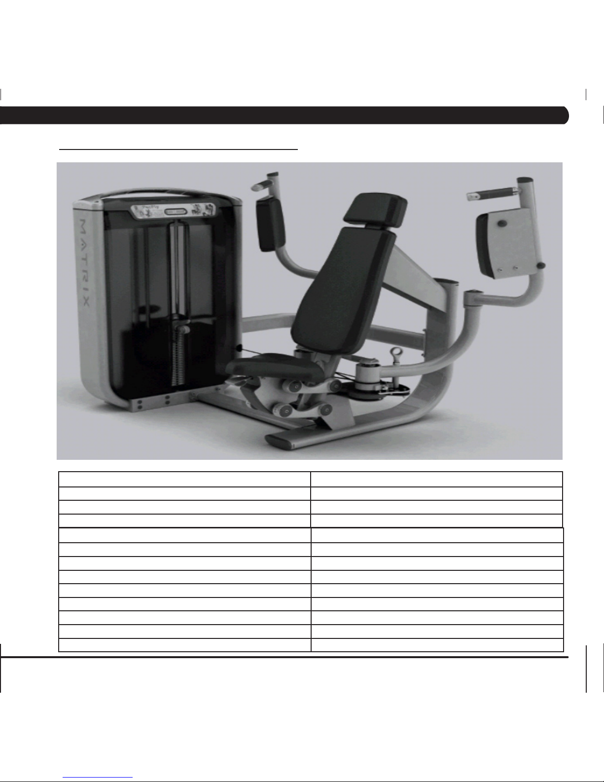
4.1 G7-S12 Pec Fly ........................................................................................................... 5
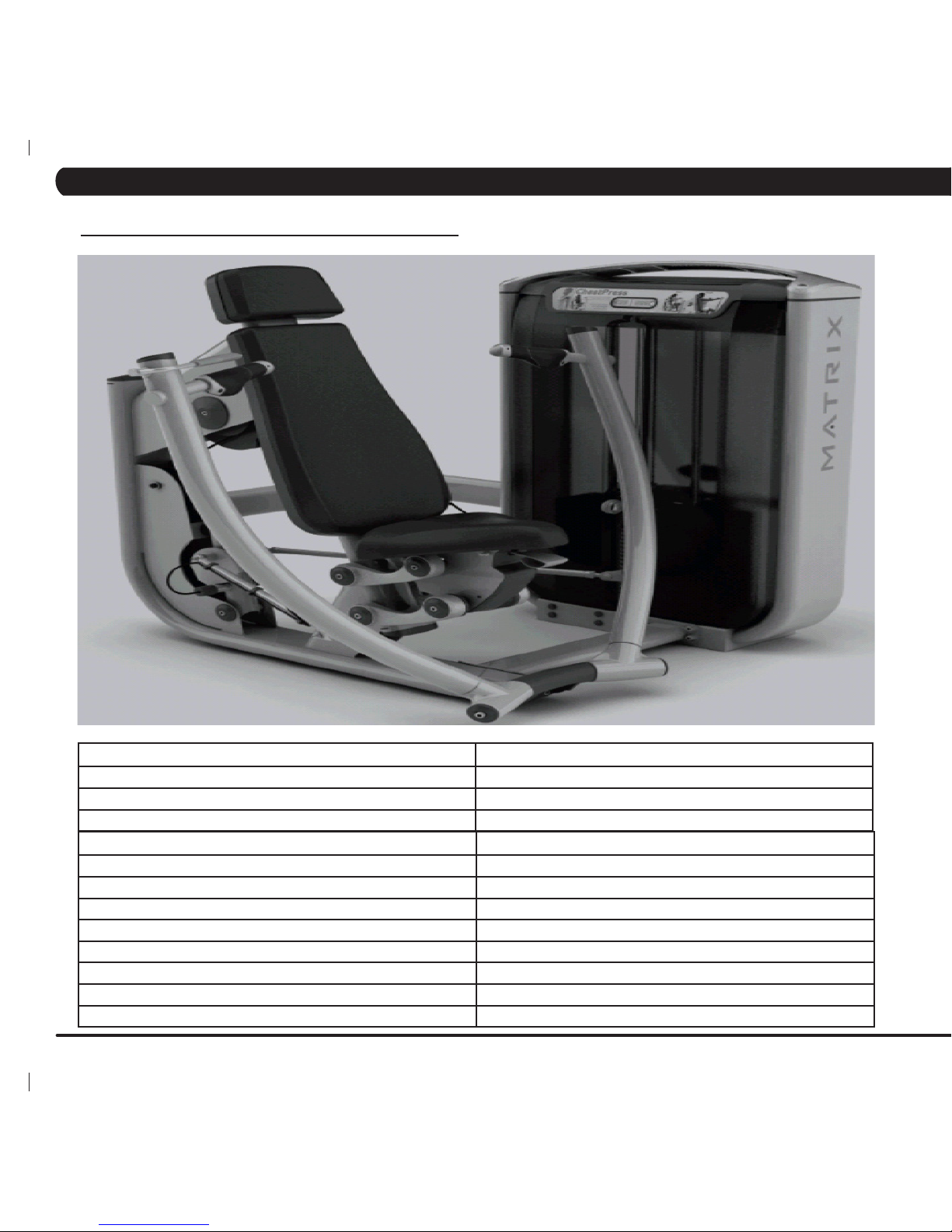
4.2 G7-S13 Chest Press .................................................................................................. 6
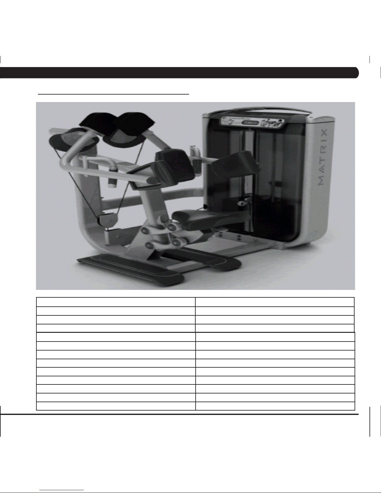
4.3 G7-S21 Lateral Raise ................................................................................................. 7
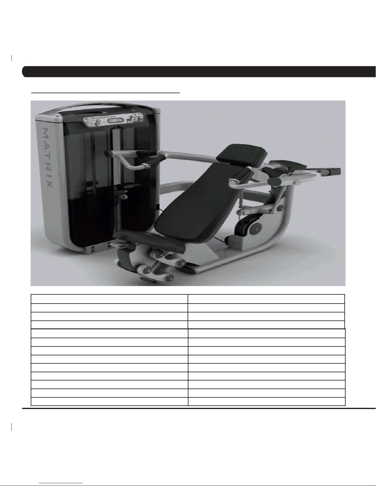
4.4 G7-S23 Shoulder Press .............................................................................................. 8
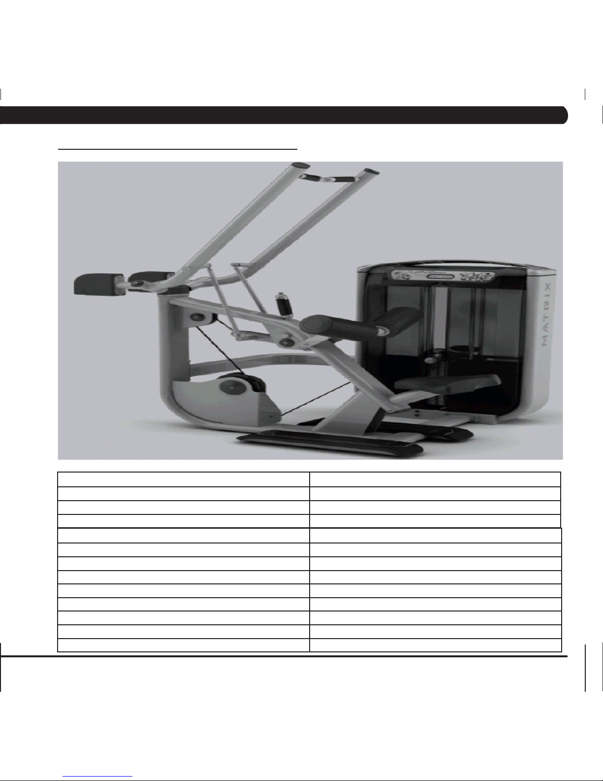
4.5 G7-S33 Lat Pull Down ................................................................................................ 9
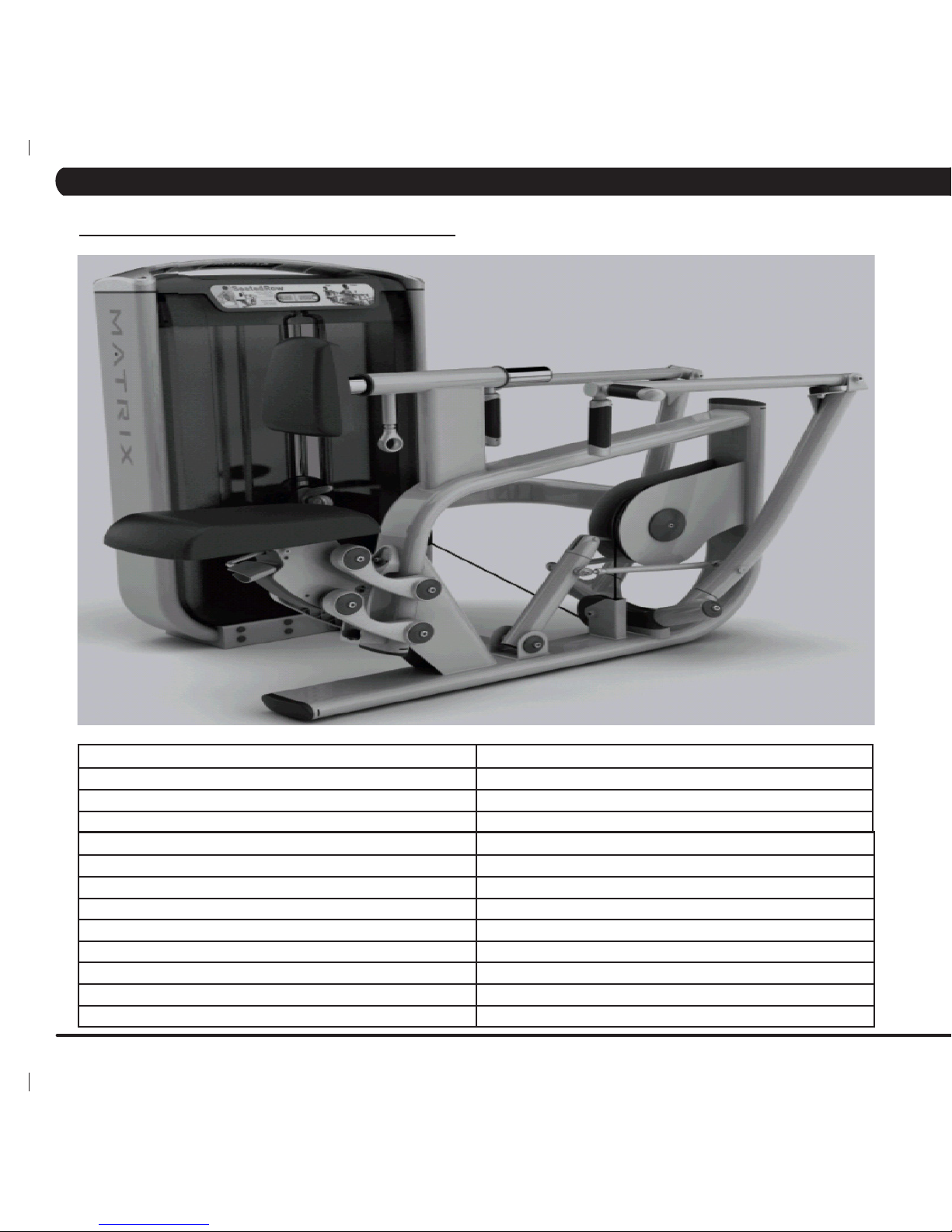
4.6 G7-S34 Seated Row ................................................................................................... 10
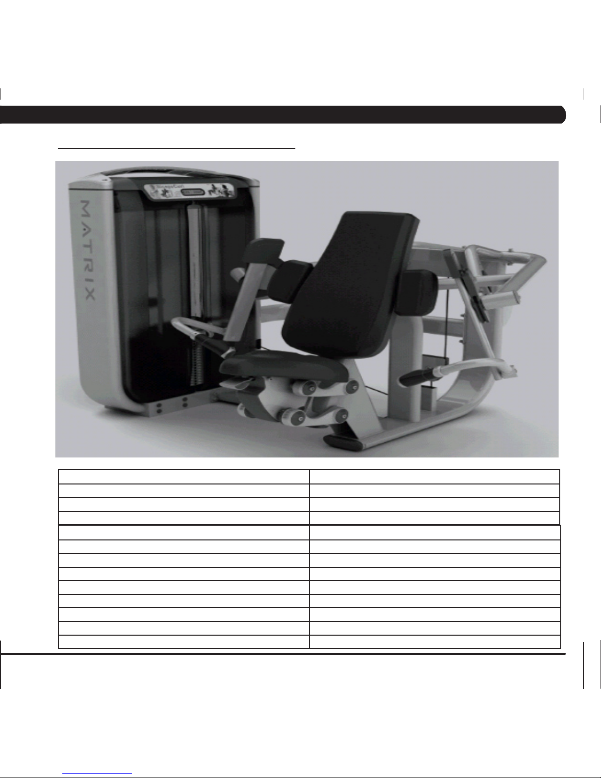
4.7 G7-S40 Arm Curl ......................................................................................................... 11
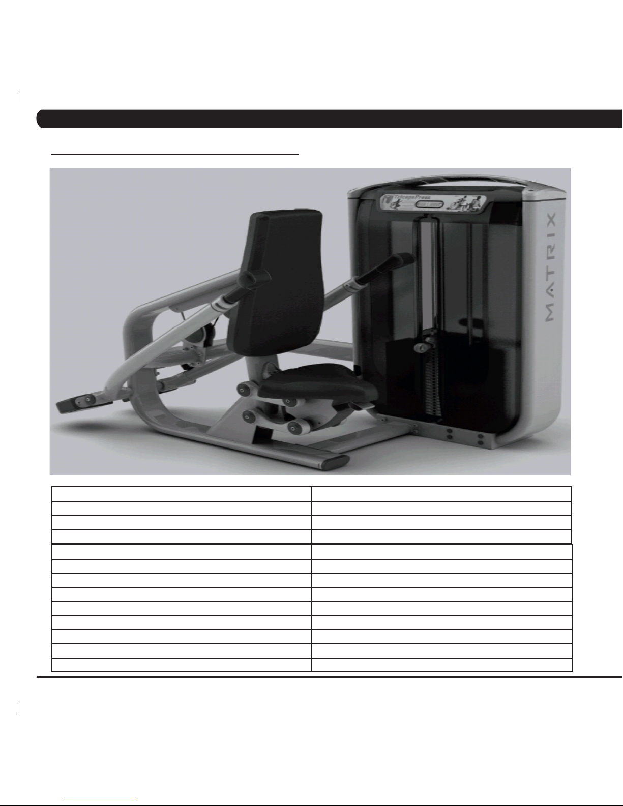
4.8 G7-S42 Tricep Pressdown .......................................................................................... 12
4.9 G7-S51 Abdominal ...................................................................................................... 13
4.10 G7-S52 Back Extension .............................................................................................. 14
4.11 G7-S55 Rotary Torso .................................................................................................. 15
4.12 G7-S57 Calf Extension ............................................................................................... 16
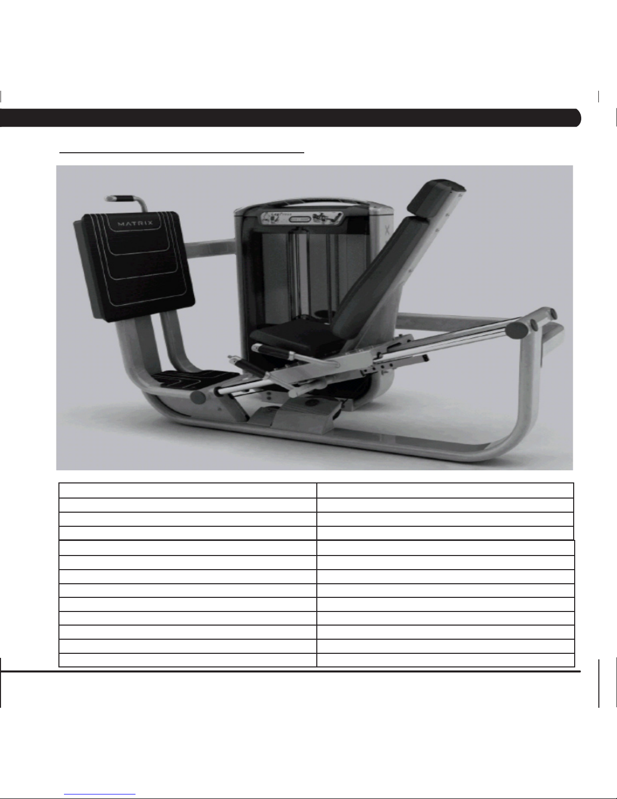
4.13 G7-S70 Leg Press ...................................................................................................... 17
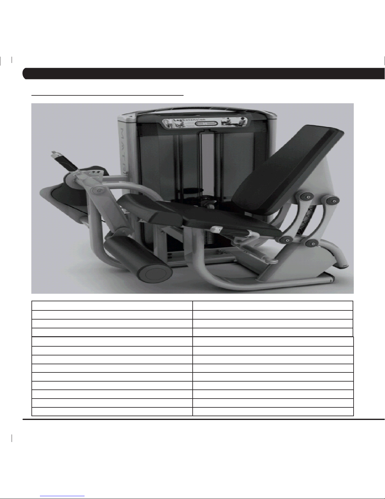
4.14 G7-S71 Leg Extension ................................................................................................ 18
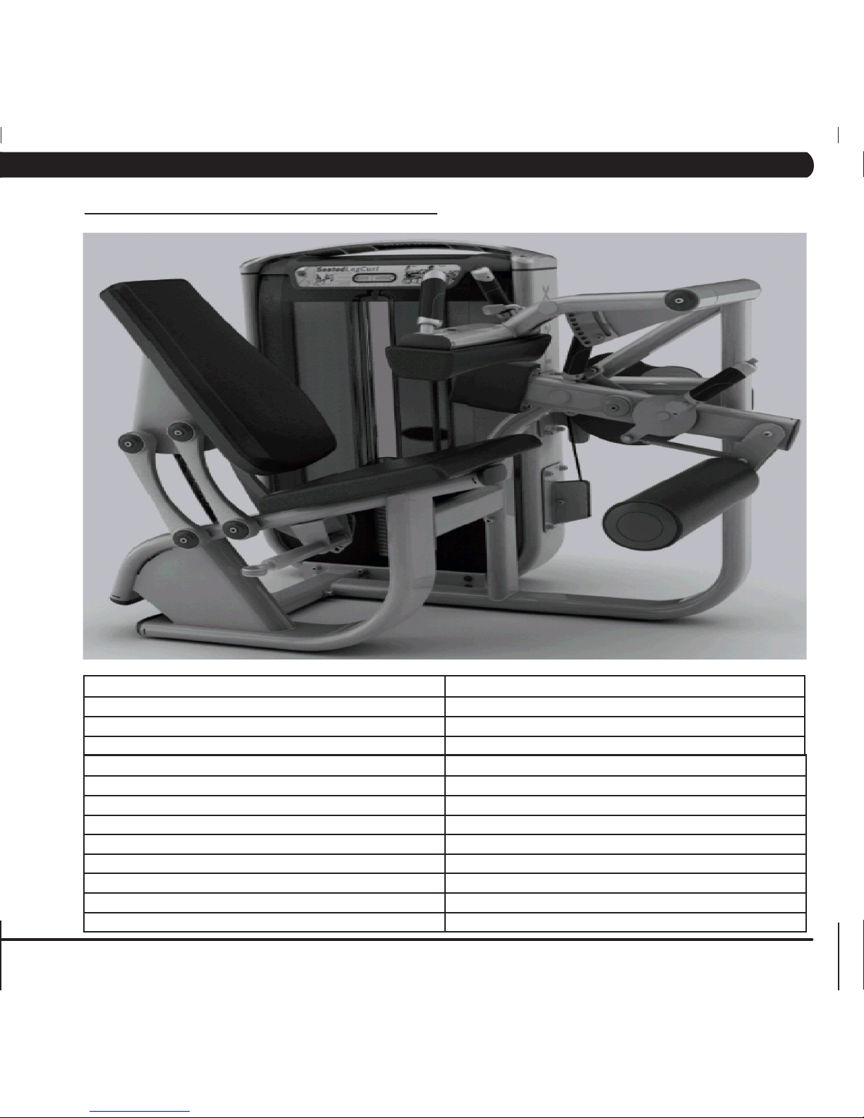
4.15 G7-S72 Seated Leg Curl ............................................................................................. 19
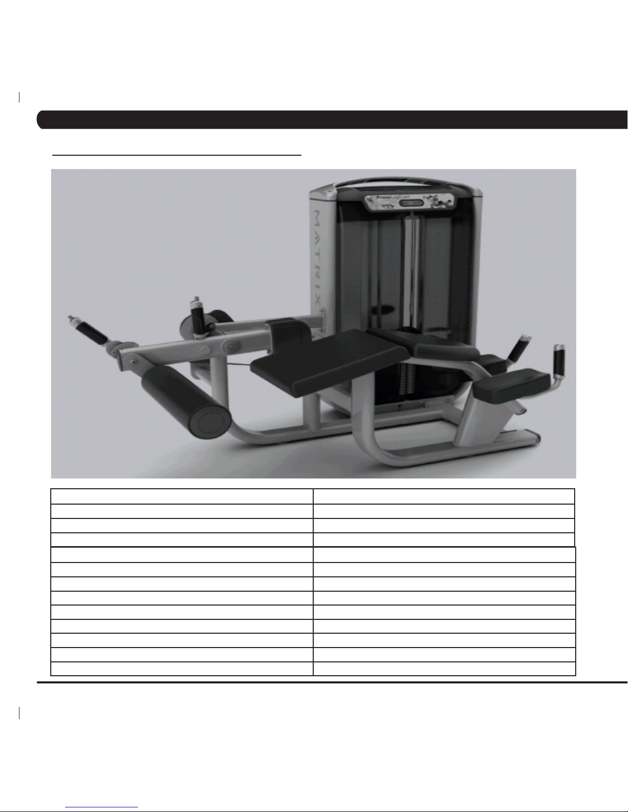
4.16 G7-S73 Prone Leg Curl .............................................................................................. 20
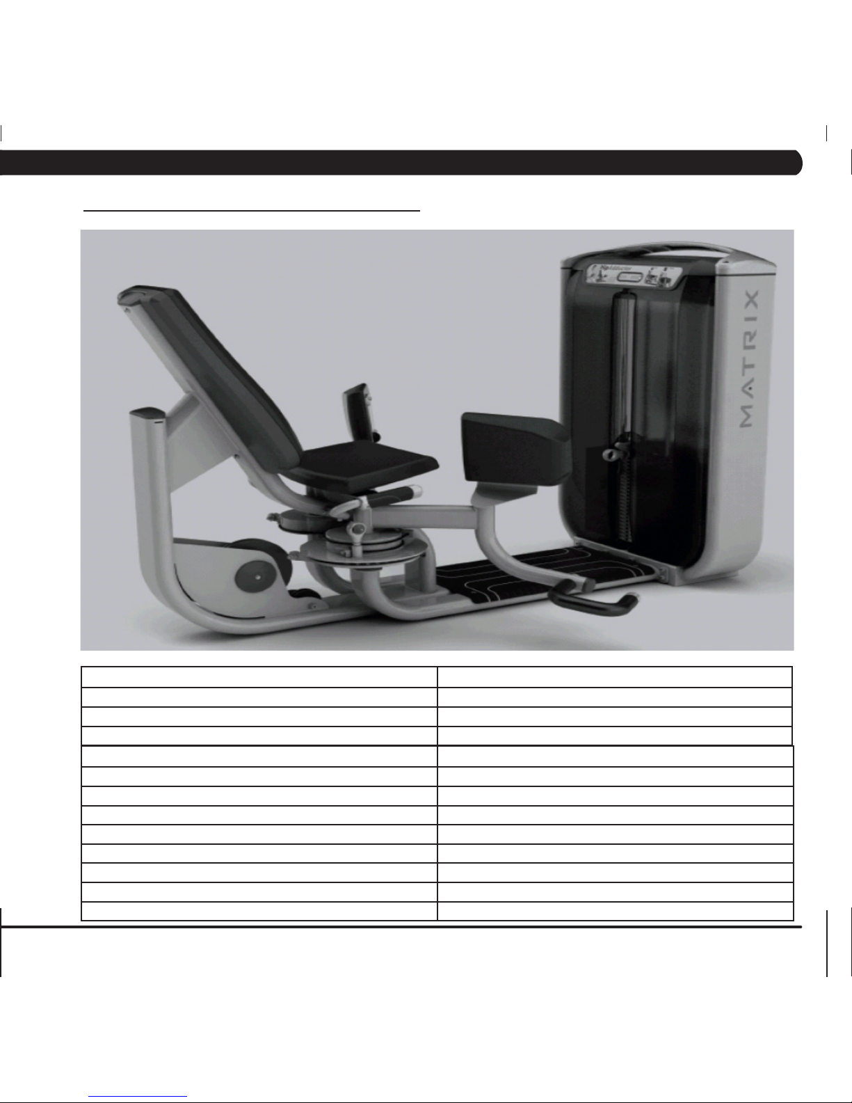
4.17 G7-S74 Hip Adductor .................................................................................................. 21
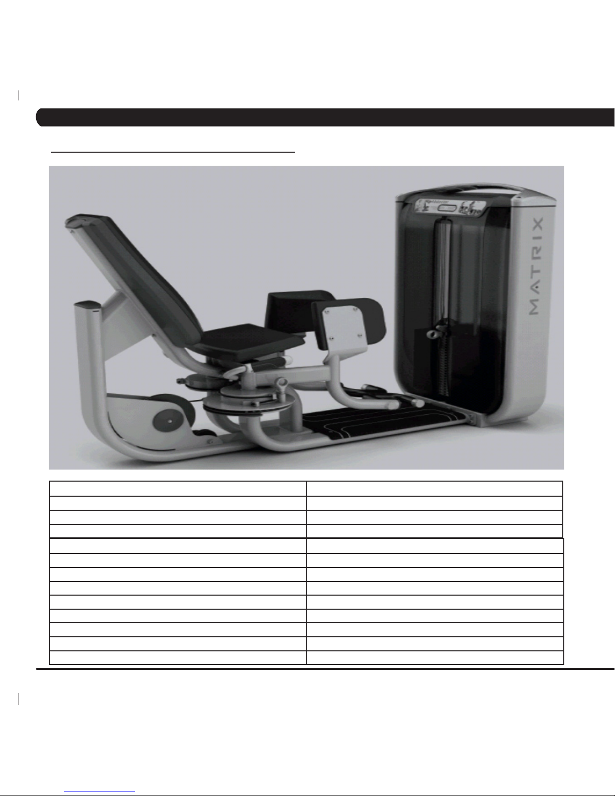
4.18 G7-S75 Hip Abductor .................................................................................................. 22
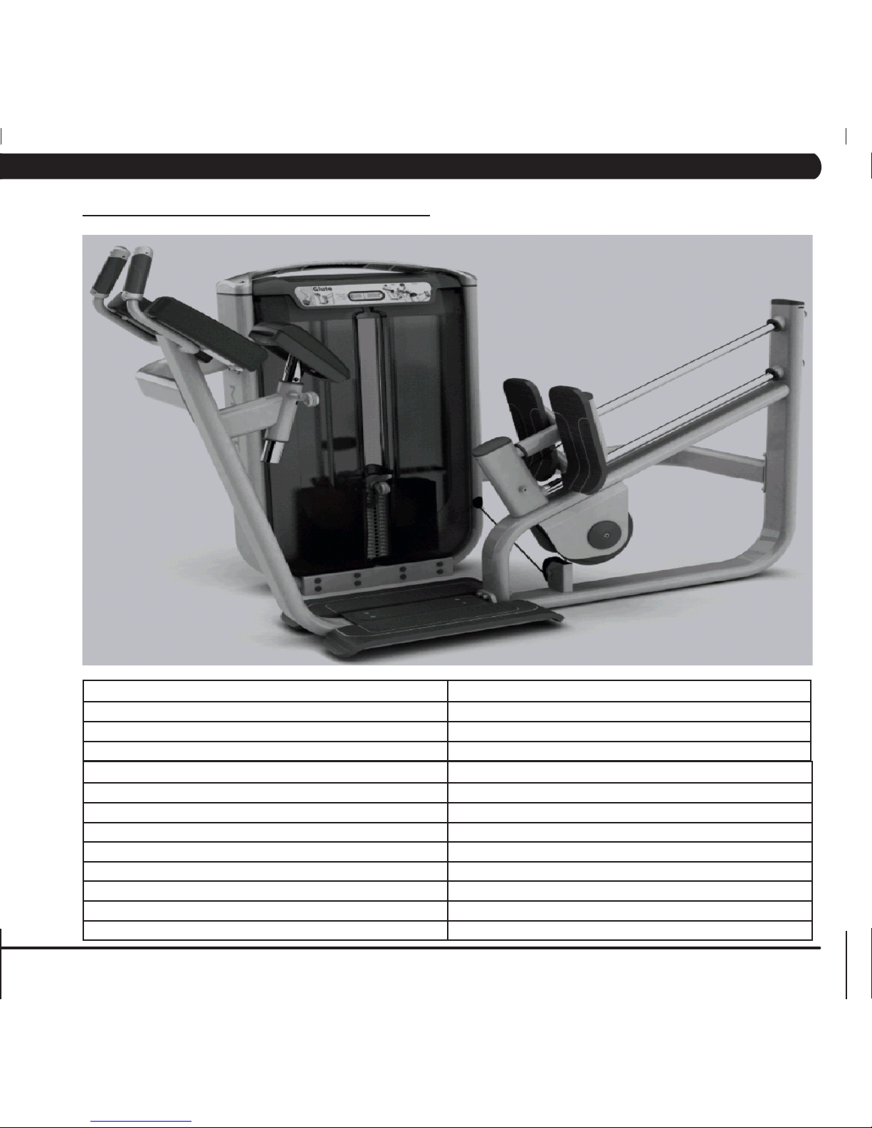
4.19 G7-S78 Glute .............................................................................................................. 23
CHAPTER 5: ASSEMBLY INSTRUCTIONS
5.1 G7-S12 Pec Fly Assembly Instructions ....................................................................... 24
5.2 G7-S13 Chest Press Assembly Instructions ............................................................... 30
5.3 G7-S21 Lateral Raise Assembly Instructions ............................................................. 37
5.4 G7-S23 Shoulder Press Assembly Instructions .......................................................... 43
5.5 G7-S33 Lat Pull Down Assembly Instructions ............................................................ 50
5.6 G7-S34 Seated Row Assembly Instructions ............................................................... 56
5.7 G7-S40 Arm Curl Assembly Instructions ..................................................................... 64
5.8 G7-S42 Tricep Pressdown Assembly Instructions ...................................................... 70
5.9 G7-S51 Abdominal Assembly Instructions .................................................................. 77
5.10 G7-S52 Back Extension Assembly Instructions .......................................................... 84
5.11 G7-S55 Rotary Torso Assembly Instructions .............................................................. 90
5.12 G7-S57 Calf Extension Assembly Instructions ........................................................... 96
5.13 G7-S70 Leg Press Assembly Instructions .................................................................. 101
5.14 G7-S71 Leg Extension Assembly Instructions ............................................................ 108
5.15 G7-S72 Seated Leg Curl Assembly Instructions ......................................................... 114
5.16 G7-S73 Prone Leg Curl Assembly Instructions .......................................................... 121
TABLE OF CONTENTS
i
Page 4

iv
TABLE OF CONTENTS
5.17 G7-S74 Hip Adductor Assembly Instructions .............................................................. 126
5.18 G7-S75 Hip Abductor Assembly Instructions .............................................................. 135
5.19 G7-S78 Glute Assembly Instructions .......................................................................... 142
CHAPTER 6: TROUBLESHOOTING
6.1 Troubleshooting - Repetition Counter Issues .............................................................. 149
6.2 Troubleshooting - Incremental Weight Pin Issues ...................................................... 151
6.3 Troubleshooting - Arms Are Uneven ........................................................................... 152
6.4 Troubleshooting - Weight Stack Pin Issues ................................................................ 153
6.5 Troubleshooting - Seat Issues .................................................................................... 154
6.6 Troubleshooting - Abdominal Arms Uneven ................................................................ 155
6.7 Troubleshooting - Pec Fly Arms are Uneven .............................................................. 156
6.8 Troubleshooting - Chest Press Arm Issues................................................................. 157
CHAPTER 7: PART REPLACEMENT INSTRUCTIONS
7.1 Testing the Unit ......................................................................................................... 158
7.2 Aluminum Wing Replacement .................................................................................... 159
7.3 Top Cover Replacement............................................................................................. 160
7.4 Repetition Counter Replacement ............................................................................... 161
7.5 Weight Stack Shroud Replacement ........................................................................... 162
7.6 Repetition Sensor Replacement ................................................................................ 163
7.7 Incremental Weight Pin Replacement ........................................................................ 164
7.8 Weight Plate Replacement ......................................................................................... 166
7.9 Weight Stack Pulley Assembly Replacement ............................................................ 168
7.10 Small Connecting Rod Replacement ......................................................................... 169
7.11 Large Connecting Rod Replacement ......................................................................... 170
7.12 Adjustable Tie Rod Replacement ............................................................................... 172
7.13 Hand Grip Replacement............................................................................................. 173
7.14 Seat Pad Adjustment Handle Replacement ............................................................... 174
7.15 Back Pad Adjustment Handle Replacement .............................................................. 175
7.16 Arm Adjustment Handle Replacement ....................................................................... 176
7.17 ROM Adjustment Handle Replacement ..................................................................... 177
7.18 Head Pad Replacement ............................................................................................. 178
7.19 Back Pad Replacement.............................................................................................. 179
7.20 Seat Pad Replacement .............................................................................................. 180
7.21 Round Pad Replacement ........................................................................................... 181
ii
Page 5
1
1
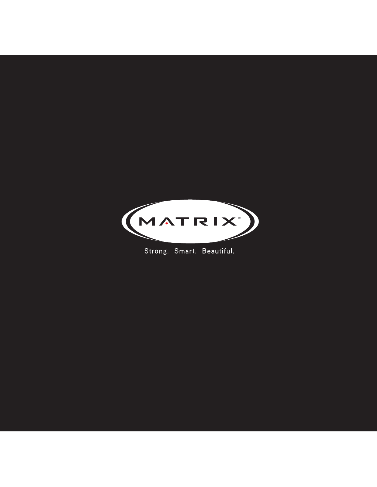
1.1 SERIAL NUMBER LOCATION
CHAPTER 1: SERIAL NUMBER LOCATION
The serial number is located at the bottom of the weight stack frame.
Page 6

2
CHAPTER 2: IMPORTANT SAFETY INSTRUCTIONS
2.1 IMPORTANT SAFETY INFORMATION
It is the sole responsibility of the purchaser of Matrix Fitness
Systems products to instruct all individuals, whether they are
the end user or supervising personnel on proper usage of the
equipment.
PROPER USAGE:
Do not use any equipment in any way other than designed or
intended by the manufacturer. It is imperative that Matrix Fitness
Systems equipment be used properly to avoid injury.
Keep hands and feet clear at all times from moving parts to avoid
injury.
WARNING: Serious injury can occur on this
equipment. Follow these precautions to avoid
injuries.
1) Never allow children on selectorized strength equipment.
Teenagers must be supervised at all times while using this
equipment.
2) All warnings and instructions should be read and proper
instruction obtained prior to use.
3) Cease exercise if you feel faint or dizzy. Obtain a medical exam
before beginning an exercise program.
4) Keep body, hair, clothing, and fitness accessories free and clear
of all moving parts.
5) Inspect the machine before use. DO NOT use the machine if it
appears damaged or inoperable.
6) Check to see that the selector pin is completely inserted into the
weight stack.
7) NEVER use the machine with the weight stack pinned in an
elevated position.
8) Never use dumbbells or other means to incrementally increase
the weight resistance. Only use the means provided directly from
the manufacturer.
9) This equipment should only be used in supervised areas where
access and control are regulated by the owner.
2.2 CHECK FOR DAMAGED PARTS
1) DO NOT use any equipment that is damaged and or has worn
or broken parts. Use only replacement parts supplied by Matrix
Fitness Systems or your local Matrix Fitness Systems dealer.
2) MAINTAIN LABELS AND NAMEPLATES: Do not remove
labels for any reason. They contain important information. If
unreadable or missing, contract Matrix Fitness Systems for a
replacement.
3) SECURE EQUIPMENT: All equipment must be secured to the
floor to stabilize and eliminate rocking or tipping over. This must be
performed by a licensed contractor.
4) MAINTAIN ALL EQUIPMENT: Preventative maintenance is
the key to smoothly operating equipment as well as keeping your
liability to a minimum. Equipment needs to be inspected at regular
intervals.
5) Ensure that any person(s) making adjustments or performing
maintenance or repair of any kind is qualified to do so. Matrix
Fitness Systems will provide service and maintenance training at
our corporate facility upon request.
Page 7
3
Preventative maintenance and daily cleaning will prolong the life and look of your Matrix Fitness Systems equipment.
3.1 PREVENTATIVE MAINTENANCE CHECKLIST
CHAPTER 3: PREVENTATIVE MAINTENANCE
ACTION FREQUENCY
Clean Upholstery Daily
Inspect Cables Daily
Clean Guide Rods Monthly
Inspect Hardware Monthly
Inspect Frame Bi-Annually
Clean Machine As Needed
Clean Grips As Needed
Clean Linear Bearing Guide Rods (Calf Press and Leg Press only) As Needed
Lubricate Linear Bearings (Calf Press and Leg Press only) As Needed or every 1.5 million cycles.
Lubricate Guide Rods As Needed
Upholstery and grips should be cleaned with a non-ammonia based cleaner (like Simple Green) or a mild soap and water. Guide rods should
be lubricated with Teflon based lubricant. Apply the lubricant to a cotton cloth and then apply up and down the guide rod.
Linear bearings should be lubricated with a SKF LGMT 2 grease.
Page 8
4
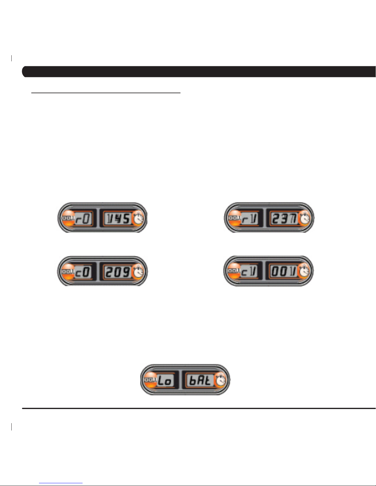
REP COUNTER INFORMATION
TO SEE THE ACCUMULATED REPS OR HOURS:
1) Hold a strong magnet to the outside of the rep counter face plate over the clock for 5 seconds to activate Service Mode. If this is not
working, a stronger magnet may be needed.
2) The rep counter will read r0 in the left window and the first 3 digits of the total reps in the right window (Figure A), record this information.
3) After 3 seconds, the rep counter will switch to r1 and the next 3 digits of the total reps are shown in the right window (Figure B). Record this
information.
4) If there are further digits in the total reps, the rep counter will switch to r2. Record this information.
5) Combine the r values to determine the total reps. Using Figures A & B below, the unit would have 237,145 total reps.
6) Once the complete number of total reps have been displayed, the rep counter will flash c0 and the first 3 digits of the accrued hours of use
are shown (Figure C).
7) After 3 seconds, if there are more digits in the accrued hours, the rep counter will switch to c1 (Figure D).
8) Combine the c values to determine the accrued hours. Using Figures C & D below, the unit would have 1,209 accrued hours.
9) Remove the magnet from the rep counter to reset to normal function.
TOTAL RESET
1) To reset all data on the rep counter, three magnets must be simultaneously held to all 3 reed switches (2 in the stack and one in the
faceplate) for 5 seconds. This clears all recorded data and cannot be recovered.
LOW BATTERY
1) When the rep counter battery gets low, the display will read Lo bAt (Figure E). At this point, the battery needs to be replaced. This WILL
NOT erase the Service Mode data.
FIGURE A FIGURE B
FIGURE C
FIGURE D
FIGURE E
3.2 REP COUNTER INFORMATION
CHAPTER 3: PREVENTATIVE MAINTENANCE
Page 9
5
CHAPTER 4: PRODUCT SPECIFICATIONS AND WARRANTY INFORMATION
4.1 G7-S12 PECTORAL FLY
WARRANTY (Valid in USA Only)
Frame (not coatings) 10 years
Structural Parts 10 years
Weight Stacks 5 years
Pulleys 5 years
Pivot Bearings 5 years
Any Items Not Specified 3 years
Labor (excluding upholstery / cables / grips / springs) 3 years
Upholstery / Cables / Grips / Springs 1 year
TECHNICAL SPECIFICATIONS
Overall Dimensions 63"L x 47"W x 52"H
Weight 592 lbs
Shipping Weight 638 lbs
Page 10
6
WARRANTY (Valid in USA Only)
Frame (not coatings) 10 years
Structural Parts 10 years
Weight Stacks 5 years
Pulleys 5 years
Pivot Bearings 5 years
Any Items Not Specified 3 years
Labor (excluding upholstery / cables / grips / springs) 3 years
Upholstery / Cables / Grips / Springs 1 year
TECHNICAL SPECIFICATIONS
Overall Dimensions 63"L x 57"W x 52"H
Weight 827 lbs
Shipping Weight 870 lbs
4.2 G7-S13 CHEST PRESS
CHAPTER 4: PRODUCT SPECIFICATIONS AND WARRANTY INFORMATION
Page 11
7
WARRANTY (Valid in USA Only)
Frame (not coatings) 10 years
Structural Parts 10 years
Weight Stacks 5 years
Pulleys 5 years
Pivot Bearings 5 years
Any Items Not Specified 3 years
Labor (excluding upholstery / cables / grips / springs) 3 years
Upholstery / Cables / Grips / Springs 1 year
TECHNICAL SPECIFICATIONS
Overall Dimensions 51"L x 42.5"W x 52"H
Weight 610 lbs
Shipping Weight 689 lbs
4.3 G7-S21 LATERAL RAISE
CHAPTER 4: PRODUCT SPECIFICATIONS AND WARRANTY INFORMATION
Page 12
8
CHAPTER 4: PRODUCT SPECIFICATIONS AND WARRANTY INFORMATION
4.4 G7-S23 SHOULDER PRESS
TECHNICAL SPECIFICATIONS
Overall Dimensions 63"L x 57"W x 52"H
Weight 827 lbs
Shipping Weight 870 lbs
WARRANTY (Valid in USA Only)
Frame (not coatings) 10 years
Structural Parts 10 years
Weight Stacks 5 years
Pulleys 5 years
Pivot Bearings 5 years
Any Items Not Specified 3 years
Labor (excluding upholstery / cables / grips / springs) 3 years
Upholstery / Cables / Grips / Springs 1 year
Page 13
9
4.5 G7-S33 LAT PULL DOWN
WARRANTY (Valid in USA Only)
Frame (not coatings) 10 years
Structural Parts 10 years
Weight Stacks 5 years
Pulleys 5 years
Pivot Bearings 5 years
Any Items Not Specified 3 years
Labor (excluding upholstery / cables / grips / springs) 3 years
Upholstery / Cables / Grips / Springs 1 year
TECHNICAL SPECIFICATIONS
Overall Dimensions 61"L x 47"W x 77"H
Weight 858 lbs
Shipping Weight 914 lbs
CHAPTER 4: PRODUCT SPECIFICATIONS AND WARRANTY INFORMATION
Page 14
10
4.6 G7-S34 SEATED ROW
WARRANTY (Valid in USA Only)
Frame (not coatings) 10 years
Structural Parts 10 years
Weight Stacks 5 years
Pulleys 5 years
Pivot Bearings 5 years
Any Items Not Specified 3 years
Labor (excluding upholstery / cables / grips / springs) 3 years
Upholstery / Cables / Grips / Springs 1 year
TECHNICAL SPECIFICATIONS
Overall Dimensions 64"L x 48"W x 52"H
Weight 646 lbs
Shipping Weight 693 lbs
CHAPTER 4: PRODUCT SPECIFICATIONS AND WARRANTY INFORMATION
Page 15
11
CHAPTER 4: PRODUCT SPECIFICATIONS AND WARRANTY INFORMATION
4.7 G7-S40 ARM CURL
TECHNICAL SPECIFICATIONS
Overall Dimensions 63"L x 67"W x 52"H
Weight 553 lbs
Shipping Weight 602 lbs
WARRANTY (Valid in USA Only)
Frame (not coatings) 10 years
Structural Parts 10 years
Weight Stacks 5 years
Pulleys 5 years
Pivot Bearings 5 years
Any Items Not Specified 3 years
Labor (excluding upholstery / cables / grips / springs) 3 years
Upholstery / Cables / Grips / Springs 1 year
Page 16
12
WARRANTY (Valid in USA Only)
Frame (not coatings) 10 years
Structural Parts 10 years
Weight Stacks 5 years
Pulleys 5 years
Pivot Bearings 5 years
Any Items Not Specified 3 years
Labor (excluding upholstery / cables / grips / springs) 3 years
Upholstery / Cables / Grips / Springs 1 year
TECHNICAL SPECIFICATIONS
Overall Dimensions 61"L x 42"W x 52"H
Weight 675 lbs
Shipping Weight 727 lbs
4.8 G7-S42 TRICEP PRESS
CHAPTER 4: PRODUCT SPECIFICATIONS AND WARRANTY INFORMATION
Page 17
13
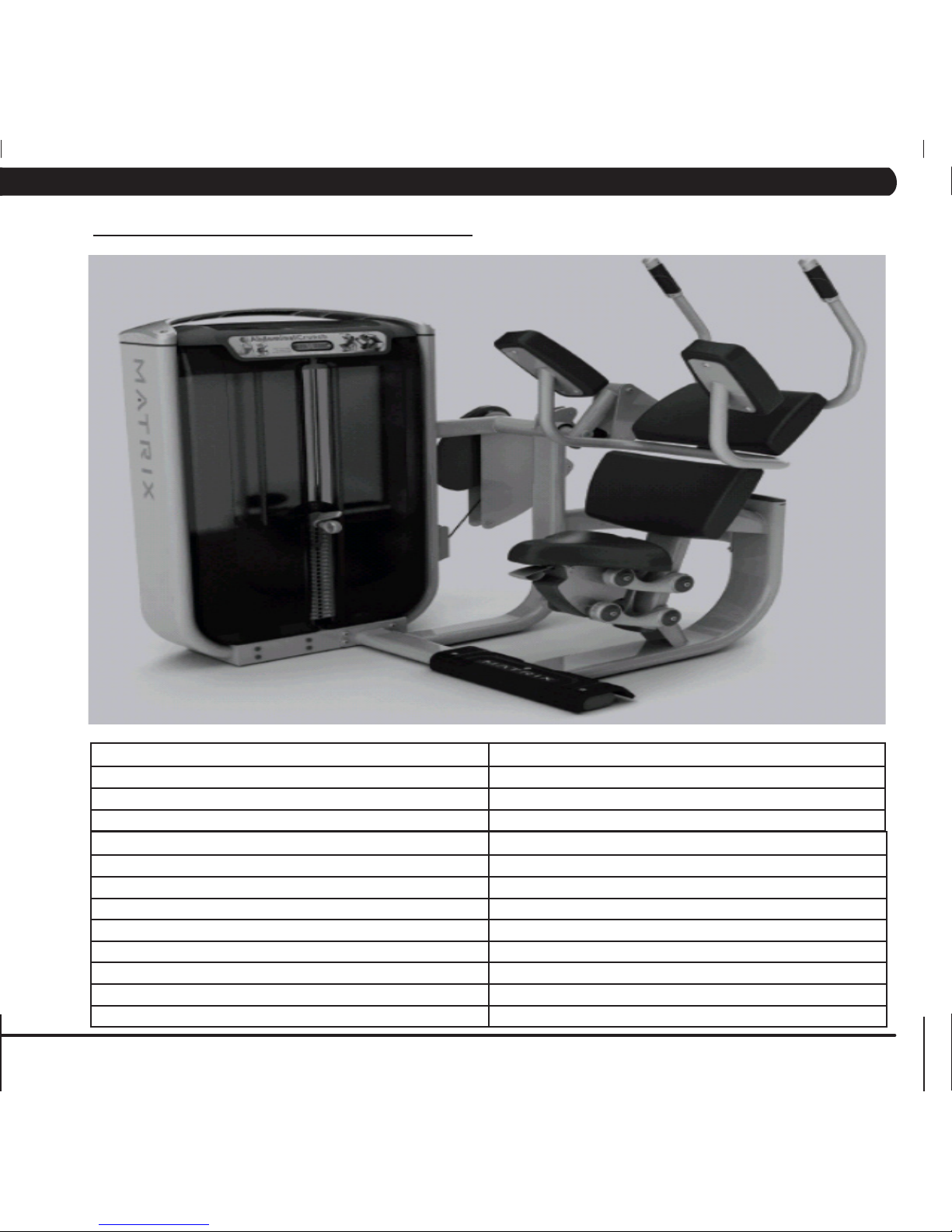
4.9 G7-S51 ABDOMINAL CRUNCH
TECHNICAL SPECIFICATIONS
Overall Dimensions 52"L x 48"W x 52"H
Weight 571 lbs
Shipping Weight 630 lbs
WARRANTY (Valid in USA Only)
Frame (not coatings) 10 years
Structural Parts 10 years
Weight Stacks 5 years
Pulleys 5 years
Pivot Bearings 5 years
Any Items Not Specified 3 years
Labor (excluding upholstery / cables / grips / springs) 3 years
Upholstery / Cables / Grips / Springs 1 year
CHAPTER 4: PRODUCT SPECIFICATIONS AND WARRANTY INFORMATION
Page 18
14
WARRANTY (Valid in USA Only)
Frame (not coatings) 10 years
Structural Parts 10 years
Weight Stacks 5 years
Pulleys 5 years
Pivot Bearings 5 years
Any Items Not Specified 3 years
Labor (excluding upholstery / cables / grips / springs) 3 years
Upholstery / Cables / Grips / Springs 1 year
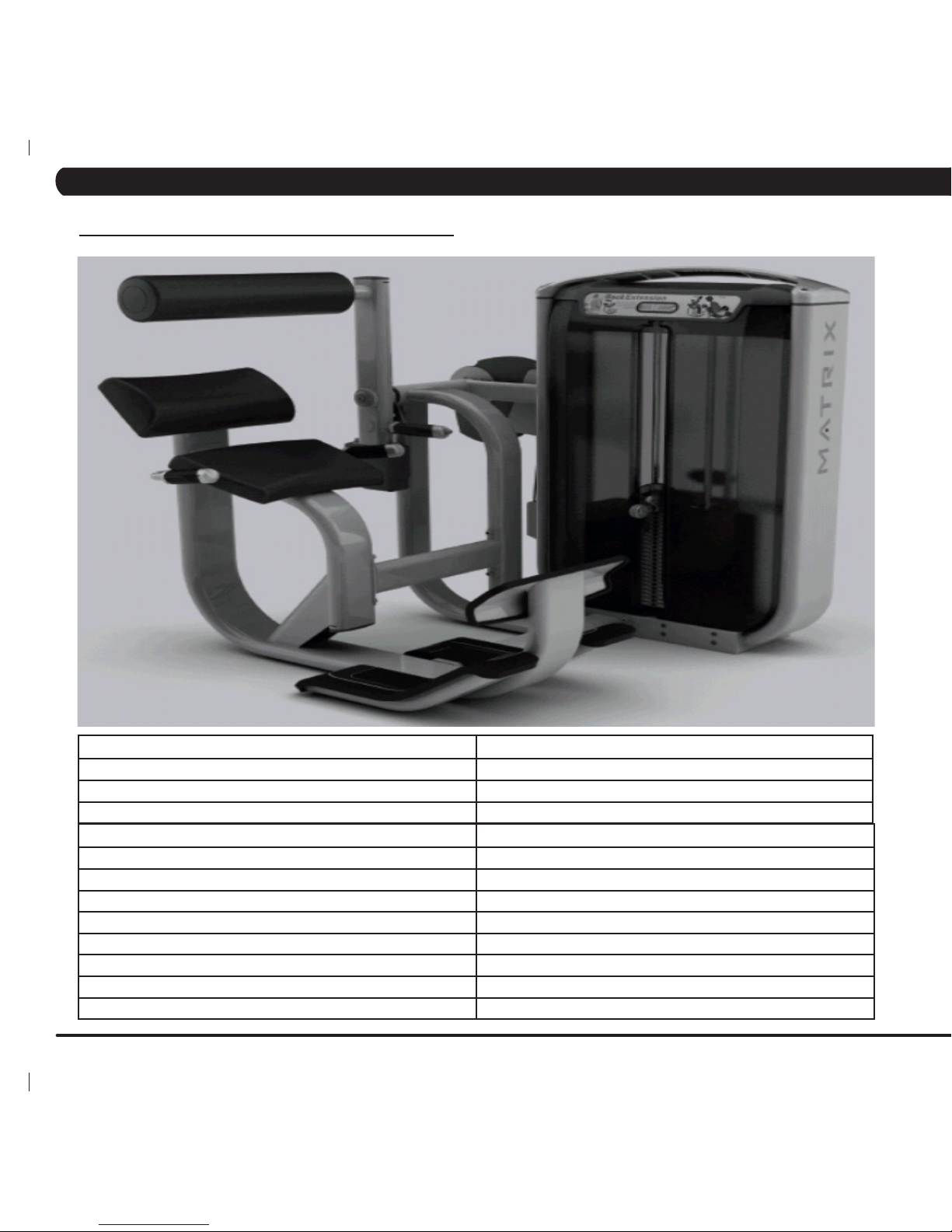
TECHNICAL SPECIFICATIONS
Overall Dimensions 75"L x 43"W x 52"H
Weight 882 lbs
Shipping Weight 946 lbs
4.10 G7-S52 BACK EXTENSION
CHAPTER 4: PRODUCT SPECIFICATIONS AND WARRANTY INFORMATION
Page 19
15
CHAPTER 4: PRODUCT SPECIFICATIONS AND WARRANTY INFORMATION
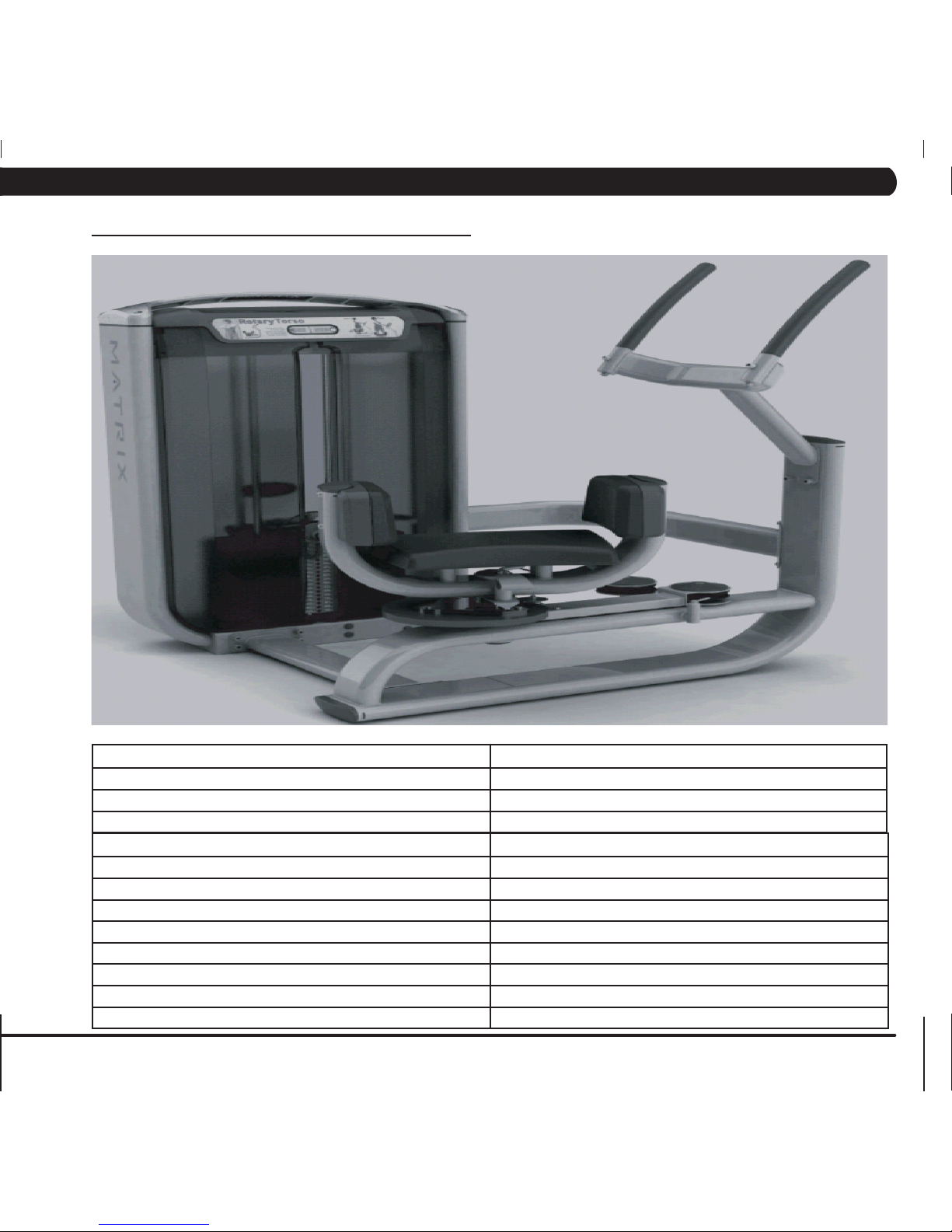
4.11 G7-S55 ROTARY TORSO
TECHNICAL SPECIFICATIONS
Overall Dimensions 45.3"L x 45"W x 54.7"H
Weight 536 lbs
Shipping Weight 569 lbs
WARRANTY (Valid in USA Only)
Frame (not coatings) 10 years
Structural Parts 10 years
Weight Stacks 5 years
Pulleys 5 years
Pivot Bearings 5 years
Any Items Not Specified 3 years
Labor (excluding upholstery / cables / grips / springs) 3 years
Upholstery / Cables / Grips / Springs 1 year
Page 20
16
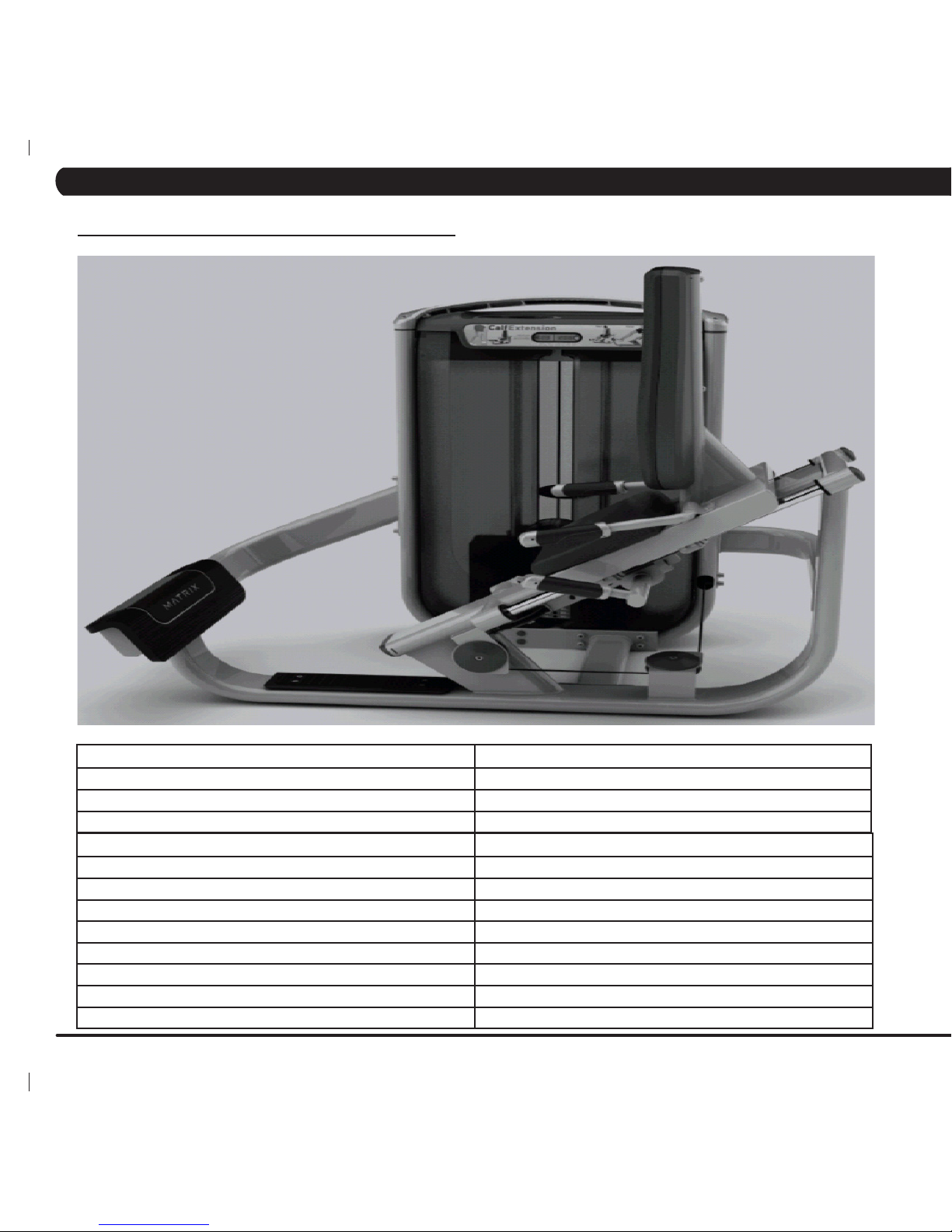
TECHNICAL SPECIFICATIONS
Overall Dimensions 59"L x 45"W x 57"H
Weight 575 lbs
Shipping Weight 617 lbs
WARRANTY (Valid in USA Only)
Frame (not coatings) 10 years
Structural Parts 10 years
Weight Stacks 5 years
Pulleys 5 years
Pivot Bearings 5 years
Any Items Not Specified 3 years
Labor (excluding upholstery / cables / grips / springs) 3 years
Upholstery / Cables / Grips / Springs 1 year
4.12 G7-S57 CALF EXTENSION
CHAPTER 4: PRODUCT SPECIFICATIONS AND WARRANTY INFORMATION
Page 21
17
4.13 G7-S70 LEG PRESS
TECHNICAL SPECIFICATIONS
Overall Dimensions 75"L x 43"W x 52"H
Weight 882 lbs
Shipping Weight 946 lbs
WARRANTY (Valid in USA Only)
Frame (not coatings) 10 years
Structural Parts 10 years
Weight Stacks 5 years
Pulleys 5 years
Pivot Bearings 5 years
Any Items Not Specified 3 years
Labor (excluding upholstery / cables / grips / springs) 3 years
Upholstery / Cables / Grips / Springs 1 year
CHAPTER 4: PRODUCT SPECIFICATIONS AND WARRANTY INFORMATION
Page 22
18
4.14 G7-S71 LEG EXTENSION
WARRANTY (Valid in USA Only)
Frame (not coatings) 10 years
Structural Parts 10 years
Weight Stacks 5 years
Pulleys 5 years
Pivot Bearings 5 years
Any Items Not Specified 3 years
Labor (excluding upholstery / cables / grips / springs) 3 years
Upholstery / Cables / Grips / Springs 1 year
TECHNICAL SPECIFICATIONS
Overall Dimensions 48"L x 47"W x 52"H
Weight 646 lbs
Shipping Weight 683 lbs
CHAPTER 4: PRODUCT SPECIFICATIONS AND WARRANTY INFORMATION
Page 23
19
4.15 G7-S72 SEATED LEG CURL
WARRANTY (Valid in USA Only)
Frame (not coatings) 10 years
Structural Parts 10 years
Weight Stacks 5 years
Pulleys 5 years
Pivot Bearings 5 years
Any Items Not Specified 3 years
Labor (excluding upholstery / cables / grips / springs) 3 years
Upholstery / Cables / Grips / Springs 1 year
TECHNICAL SPECIFICATIONS
Overall Dimensions 55"L x 46"W x 52"H
Weight 666 lbs
Shipping Weight 740 lbs
CHAPTER 4: PRODUCT SPECIFICATIONS AND WARRANTY INFORMATION
Page 24
20
WARRANTY (Valid in USA Only)
Frame (not coatings) 10 years
Structural Parts 10 years
Weight Stacks 5 years
Pulleys 5 years
Pivot Bearings 5 years
Any Items Not Specified 3 years
Labor (excluding upholstery / cables / grips / springs) 3 years
Upholstery / Cables / Grips / Springs 1 year
TECHNICAL SPECIFICATIONS
Overall Dimensions 68"L x 44"W x 52"H
Weight 581 lbs
Shipping Weight 638 lbs
4.16 G7-S73 PRONE LEG CURL
CHAPTER 4: PRODUCT SPECIFICATIONS AND WARRANTY INFORMATION
Page 25
21
WARRANTY (Valid in USA Only)
Frame (not coatings) 10 years
Structural Parts 10 years
Weight Stacks 5 years
Pulleys 5 years
Pivot Bearings 5 years
Any Items Not Specified 3 years
Labor (excluding upholstery / cables / grips / springs) 3 years
Upholstery / Cables / Grips / Springs 1 year
TECHNICAL SPECIFICATIONS
Overall Dimensions 68"L x 65"W x 52"H
Weight 597 lbs
Shipping Weight 657 lbs
4.17 G7-S74 HIP ADDUCTOR
CHAPTER 4: PRODUCT SPECIFICATIONS AND WARRANTY INFORMATION
Page 26
22
WARRANTY (Valid in USA Only)
Frame (not coatings) 10 years
Structural Parts 10 years
Weight Stacks 5 years
Pulleys 5 years
Pivot Bearings 5 years
Any Items Not Specified 3 years
Labor (excluding upholstery / cables / grips / springs) 3 years
Upholstery / Cables / Grips / Springs 1 year
TECHNICAL SPECIFICATIONS
Overall Dimensions 63"L x 57"W x 52"H
Weight 627 lbs
Shipping Weight 670 lbs
4.18 G7-S75 HIP ABDUCTOR
CHAPTER 4: PRODUCT SPECIFICATIONS AND WARRANTY INFORMATION
Page 27
23
4.19 G7-S78 GLUTE
CHAPTER 4: PRODUCT SPECIFICATIONS AND WARRANTY INFORMATION
WARRANTY (Valid in USA Only)
Frame (not coatings) 10 years
Structural Parts 10 years
Weight Stacks 5 years
Pulleys 5 years
Pivot Bearings 5 years
Any Items Not Specified 3 years
Labor (excluding upholstery / cables / grips / springs) 3 years
Upholstery / Cables / Grips / Springs 1 year
TECHNICAL SPECIFICATIONS
Overall Dimensions 80"L x 38"W x 54"H
Weight 511 lbs
Shipping Weight 544 lbs
Page 28
24
5.1 G7-S12 PECTORAL FLY ASSEMBLY INSTRUCTIONS
CHAPTER 5: ASSEMBLY INSTRUCTIONS
UNPACKING THE G7-S12 PECTORAL FLY
Thank you for purchasing the Matrix Fitness Systems Pectoral Fly. This machine is an EN957-1 and E9576-2 compliant Class S product. Your
Matrix Pectoral Fly is inspected before it is packaged. It is shipped in multiple pieces to facilitate the compact packaging of the machine. Prior
to assembly, confirm all the components by matching them with the exploded diagrams. The weight stack is shipped in separate packaging to
reduce the weight of this box. Carefully unpack the unit from this box and dispose of the packing materials in accordance with your local laws.
CAUTION
The weight of the Matrix Fitness Systems Pectoral Fly is 214 lbs (97 kg) not including the weight stack. The weight stack tower is packaged
completely assembled for ease of installation; use extra caution when removing the unit from its pallet during assembly. The weight stack for
this machine is 378 lbs (174 kg). To avoid injury to yourself and prevent damage to the frame components, be sure to have proper assistance
removing the frame pieces from this box. Be sure to install the equipment on a stable base, properly level the machine and leave at least two
feet of clearance to enter and exit the machine. Maximum user weight for this machine is 300 lbs.
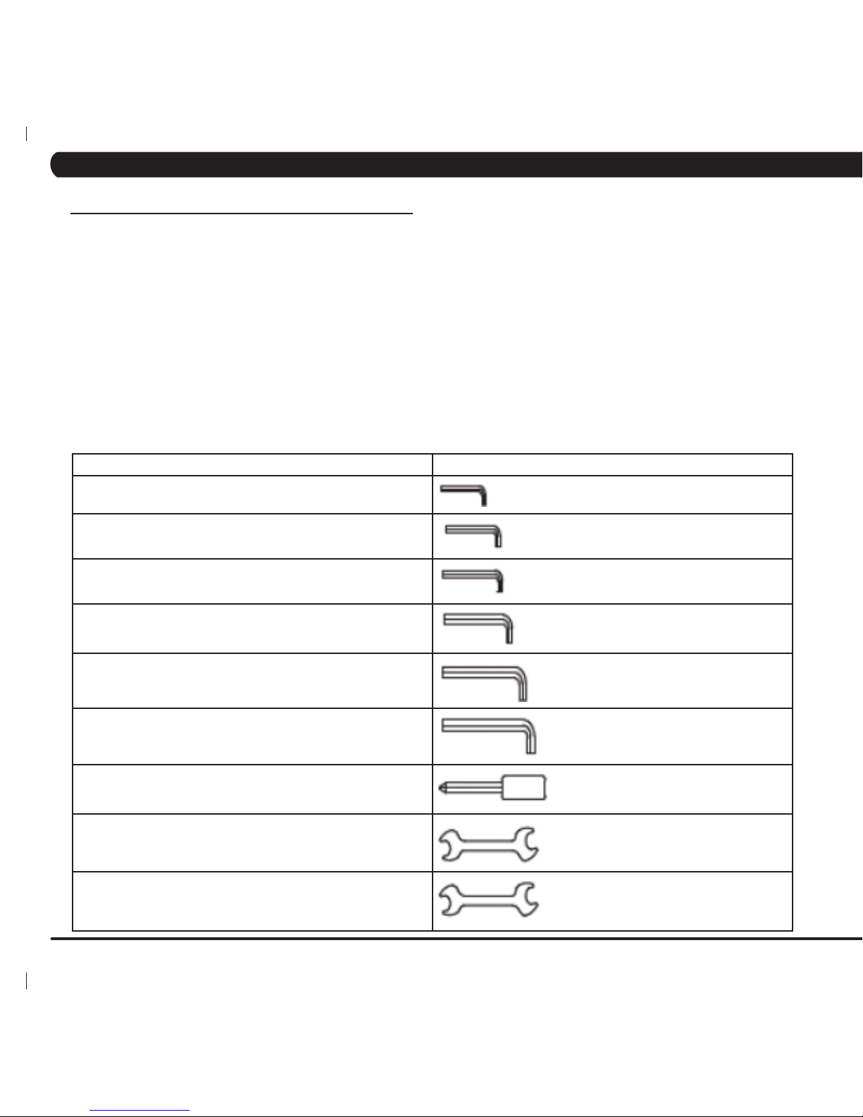
INCLUDED TOOLS REQUIRED FOR ASSEMBLY
3 mm L-Shaped Allen Wrench
4 mm L-Shaped Allen Wrench
5 mm L-Shaped Allen Wrench
6 mm L-Shaped Allen Wrench
8 mm L-Shaped Allen Wrench
10 mm L-Shaped Allen Wrench
Phillips Screwdriver
8 mm Open-End Wrench
17 mm Open-End Wrench
Page 29
25
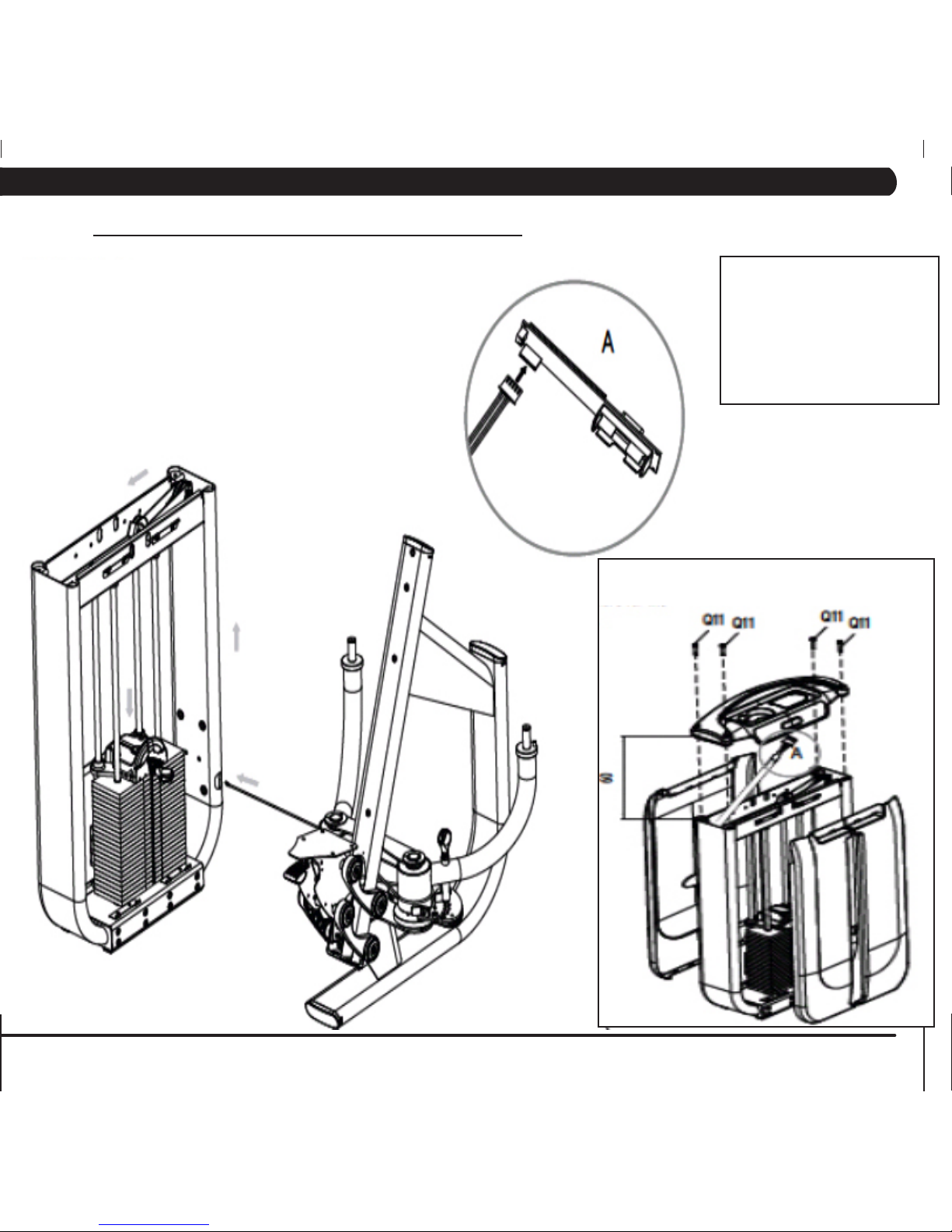
Lift the aluminum wing and top cover, then take
apart the front and rear shields. Q11 bolts will
not be used anymore for the wing and cover
re-assembly.
Item Description Quantity
F16 Screw (M10 x 30L) 10
F17 Flat Washer (M10) 8
F18 Lock Washer (M10) 6
Q11 Screw (M8 x 75L) 4
Z02 Nylon Nut (M10) 4
Z05 Arc Flat Washer 10
Z07 Screw (M10 x 75L) 2
Z15 Screw (M10 x 135L) 2
STEP 1
5.1 G7-S12 PECTORAL FLY ASSEMBLY INSTRUCTIONS - CONTINUED
CHAPTER 5: ASSEMBLY INSTRUCTIONS
Page 30
26
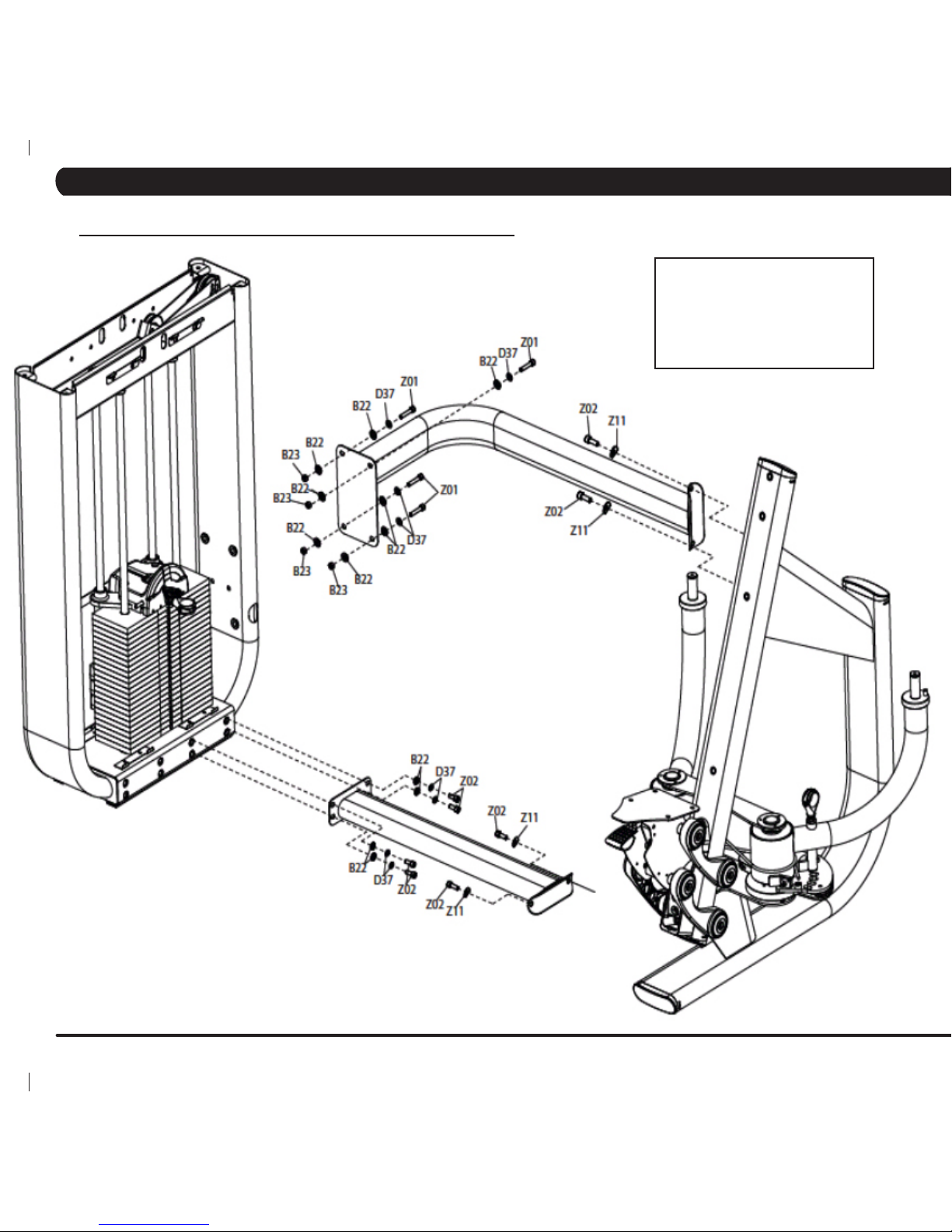
Item Description Quantity
B22 Flat Washer (M10) 12
B23 Nylon Nut (M10) 4
D37 Lock Washer (M10) 8
Z01 Screw (M10 x 75L) 4
Z02 Screw (M10 x 30L) 8
Z11 Arc Flat Washer 4
STEP 2
5.1 G7-S12 PECTORAL FLY ASSEMBLY INSTRUCTIONS - CONTINUED
CHAPTER 5: ASSEMBLY INSTRUCTIONS
Page 31

27
Item Description Quantity
D22 Pulley Cover 2
Z11 Stopper Bolt 2
Z13 Screw (M8 x 60L) 4
Z26 Screw (M8 x 20L) 2
Z27 C Clamp 2
Z32 Flat Washer (M26) 2
STEP 3
5.1 G7-S12 PECTORAL FLY ASSEMBLY INSTRUCTIONS - CONTINUED
CHAPTER 5: ASSEMBLY INSTRUCTIONS
Page 32

28
Item Description Quantity
Z04 Screw (M10 x 75L) 4
Z05 Screw (M10 x 20L) 4
STEP 4
5.1 G7-S12 PECTORAL FLY ASSEMBLY INSTRUCTIONS - CONTINUED
CHAPTER 5: ASSEMBLY INSTRUCTIONS
Page 33

29
Lift the wing and top cover, then assemble the
front and rear shields to the frame.
Item Description Quantity
Z17 Screw (M8 x 60L) 4
5.1 G7-S12 PECTORAL FLY ASSEMBLY INSTRUCTIONS - CONTINUED
STEP 5
CHAPTER 5: ASSEMBLY INSTRUCTIONS
Page 34

30
UNPACKING THE G7-S13 CHEST PRESS
Thank you for purchasing the Matrix Fitness Systems Chest Press. This machine is an EN957-1 and E9576-2 compliant Class S product. Your
Matrix Chest Press is inspected before it is packaged. It is shipped in multiple pieces to facilitate the compact packaging of the machine. Prior
to assembly, confirm all the components by matching them with the exploded diagrams. The weight stack is shipped in separate packaging to
reduce the weight of this box. Carefully unpack the unit from this box and dispose of the packing materials in accordance with your local laws.
CAUTION
The weight of the Matrix Fitness Systems Chest Press is 398 lbs (181 kg) not including the weight stack. The weight stack tower is packaged
completely assembled for ease of installation; use extra caution when removing the unit from its pallet during assembly. The weight stack for
this machine is 429 lbs (195 kg). To avoid injury to yourself and prevent damage to the frame components, be sure to have proper assistance
removing the frame pieces from this box. Be sure to install the equipment on a stable base, properly level the machine and leave at least two
feet of clearance to enter and exit the machine. Maximum user weight for this machine is 300 lbs.
INCLUDED TOOLS REQUIRED FOR ASSEMBLY
3 mm L-Shaped Allen Wrench
4 mm L-Shaped Allen Wrench
5 mm L-Shaped Allen Wrench
6 mm L-Shaped Allen Wrench
8 mm L-Shaped Allen Wrench
10 mm L-Shaped Allen Wrench
Phillips Screwdriver
8 mm Open-End Wrench
17 mm Open-End Wrench
5.2 G7-S13 CHEST PRESS ASSEMBLY INSTRUCTIONS
CHAPTER 5: ASSEMBLY INSTRUCTIONS
Page 35

31
5.2 G7-S13 CHEST PRESS ASSEMBLY INSTRUCTIONS - CONTINUED
Item Description Quantity
B27 Nut (M10 x 1.5P) 4
B30 Fix Washer (M10) 12
C36 Lock Washer (M10) 8
Q11 Screw (M8 x 60L) 4
Z03 Screw (M10 x 75L) 4
Z04 Screw (M10 x 12L) 12
Z21 Washer;Arc 4
STEP 1
CHAPTER 5: ASSEMBLY INSTRUCTIONS
Lift the aluminum wing and top
cover, then take apart the front and
rear shields. Q11 bolts will not be
used anymore for the wing and
cover re-assembly.
Page 36

32
CHAPTER 5: ASSEMBLY INSTRUCTIONS
5.2 G7-S13 CHEST PRESS ASSEMBLY INSTRUCTIONS - CONTINUED
Item Description Quantity
B27 Nut (M10 x 1.5P) 2
B30 Fix Washer (M10) 2
C17 Small Pulley Cover 1
C24 Large Pulley Cover 1
F06 Stopper Plate 1
F07 Screw (M6 x 45L) 2
F13 Flat Washer (M10) 2
F16 Fixing Block 1
H40 Fixing Pin 1
Z05 Screw (M10 x 105L) 1
Z15 Clip;Inner C 1
Z22 Flat Washer (M8) 1
STEP 2
Page 37

33
5.2 G7-S13 CHEST PRESS ASSEMBLY INSTRUCTIONS - CONTINUED
CHAPTER 5: ASSEMBLY INSTRUCTIONS
Item Description Quantity
C17 Pulley Cover 8
C31 Screw (M8 x 25L) 8
J18 Connecting Rod 4
J20 Spring; Swirl 2
STEP 3
Page 38

34
5.2 G7-S13 CHEST PRESS ASSEMBLY INSTRUCTIONS - CONTINUED
CHAPTER 5: ASSEMBLY INSTRUCTIONS
Item Description Quantity
C20 Base Fixing Cover 2
D11 Fixing Axle 2
D13 Clip;External;C Type 2
D49 Clip;Internal;C Type 2
D50 Wave Washer 2
H28 Cable 1
H30 Steel Clamp 2
Z02 Screw (M10 x 15L) 2
Z06 Screw (M6 x 10L) 2
Z09 Screw (M6 x 60L) 2
Z10 Flat Washer (M6) 6
Z13 Nut Cap 2
Z17 Settle Screw 3
STEP 4
Page 39

35
Item Description Quantity
Z20 Screw (M8 x 60L) 4
CHAPTER 5: ASSEMBLY INSTRUCTIONS
5.2 G7-S13 CHEST PRESS ASSEMBLY INSTRUCTIONS - CONTINUED
STEP 5
Page 40

36
5.2 G7-S13 CHEST PRESS ASSEMBLY INSTRUCTIONS - CONTINUED
CHAPTER 5: ASSEMBLY INSTRUCTIONS
Item Description Quantity
Z18 Screw (M10 x 75L) 4
Z19 Screw (M10 x 15L) 4
STEP 6
Page 41

37
UNPACKING THE G7-S21 LATERAL RAISE
Thank you for purchasing the Matrix Fitness Systems Lateral Raise. This machine is an EN957-1 and E9576-2 compliant Class S product.
Your Matrix Lateral Raise is inspected before it is packaged. It is shipped in multiple pieces to facilitate the compact packaging of the machine.
Prior to assembly, confirm all the components by matching them with the exploded diagrams. The weight stack is shipped in separate
packaging to reduce the weight of this box. Carefully unpack the unit from this box and dispose of the packing materials in accordance with
your local laws.
CAUTION
The weight of the Matrix Fitness Systems Lateral Raise is 411 lbs (186 kg) not including the weight stack. The weight stack tower is packaged
completely assembled for ease of installation; use extra caution when removing the unit from its pallet during assembly. The weight stack for
this machine is 199 lbs (90 kg). To avoid injury to yourself and prevent damage to the frame components, be sure to have proper assistance
removing the frame pieces from this box. Be sure to install the equipment on a stable base, properly level the machine and leave at least two
feet of clearance to enter and exit the machine. Maximum user weight for this machine is 300 lbs.
INCLUDED TOOLS REQUIRED FOR ASSEMBLY
3 mm L-Shaped Allen Wrench
4 mm L-Shaped Allen Wrench
5 mm L-Shaped Allen Wrench
6 mm L-Shaped Allen Wrench
8 mm L-Shaped Allen Wrench
10 mm L-Shaped Allen Wrench
Phillips Screwdriver
8 mm Open-End Wrench
17 mm Open-End Wrench
5.3 G7-S21 LATERAL RAISE ASSEMBLY INSTRUCTIONS
CHAPTER 5: ASSEMBLY INSTRUCTIONS
Page 42

38
Item Description Quantity
B22 Flat Washer (M10) 12
Z01 Screw (M10 x 75L) 4
Z02 Nylon Nut (M10) 4
Z03 Spring Washer (M10) 8
Z04 Screw (M10 x 30L) 14
Z05 Arc Washer 10
STEP 1
Lift the aluminum wing and top cover, then take apart the front and rear shields.
Q11 bolts will not be used anymore for the wing and cover re-assembly.
5.3 G7-S21 LATERAL RAISE ASSEMBLY INSTRUCTIONS - CONTINUED
CHAPTER 5: ASSEMBLY INSTRUCTIONS
Page 43

39
Item Description Quantity
B22 Flat Washer (M10) 4
B23 Nylon Nut (M10) 2
C31 Flat Washer (M8) 2
C43 Small Pulley Cover 2
F10 Fixing Plate 1
F15 Cable Stopper 1
Z07 C Ring 2
Z08 Wave Spring 4
Z09 Screw (M10 x 20L) 2
STEP 2
5.3 G7-S21 LATERAL RAISE ASSEMBLY INSTRUCTIONS - CONTINUED
CHAPTER 5: ASSEMBLY INSTRUCTIONS
Page 44

40
Item Description Quantity
C17 Small Pulley Cover 8
C30 Screw (M10 x 25L) 8
J18 Connecting Rod 4
J20 Swirl Spring 2
J32 Shaft 4
STEP 3
5.3 G7-S21 LATERAL RAISE ASSEMBLY INSTRUCTIONS - CONTINUED
CHAPTER 5: ASSEMBLY INSTRUCTIONS
Page 45

41
Item Description Quantity
C31 Screw; Hex Socket 4
D39 Screw (M10 x 20L) 10
Z06 Screw (M8 x 20L) 4
Z19 Screw (M10 x 20L) 4
STEP 4
5.3 G7-S21 LATERAL RAISE ASSEMBLY INSTRUCTIONS - CONTINUED
CHAPTER 5: ASSEMBLY INSTRUCTIONS
Page 46

42
Lift the wing and top cover, then assemble the
front and rear shields to the frame.
STEP 5
5.3 G7-S21 LATERAL RAISE ASSEMBLY INSTRUCTIONS - CONTINUED
CHAPTER 5: ASSEMBLY INSTRUCTIONS
Page 47

43
5.4 G7-S23 SHOULDER PRESS ASSEMBLY INSTRUCTIONS
CHAPTER 5: ASSEMBLY INSTRUCTIONS
UNPACKING THE G7-S23 SHOULDER PRESS
Thank you for purchasing the Matrix Fitness Systems Shoulder Press. This machine is an EN957-1 and E9576-2 compliant Class S
product. Your Matrix Shoulder Press is inspected before it is packaged. It is shipped in multiple pieces to facilitate the compact packaging
of the machine. Prior to assembly, confirm all the components by matching them with the exploded diagrams. The weight stack is shipped
in separate packaging to reduce the weight of this box. Carefully unpack the unit from this box and dispose of the packing materials in
accordance with your local laws.
CAUTION
The weight of the Matrix Fitness Systems Shoulder Press is 398 lbs (181 kg) not including the weight stack. The weight stack tower is
packaged completely assembled for ease of installation; use extra caution when removing the unit from its pallet during assembly. The weight
stack for this machine is 429 lbs (195 kg). To avoid injury to yourself and prevent damage to the frame components, be sure to have proper
assistance removing the frame pieces from this box. Be sure to install the equipment on a stable base, properly level the machine and leave at
least two feet of clearance to enter and exit the machine. Maximum user weight for this machine is 300 lbs.
INCLUDED TOOLS REQUIRED FOR ASSEMBLY
3 mm L-Shaped Allen Wrench
4 mm L-Shaped Allen Wrench
5 mm L-Shaped Allen Wrench
6 mm L-Shaped Allen Wrench
8 mm L-Shaped Allen Wrench
10 mm L-Shaped Allen Wrench
Phillips Screwdriver
8 mm Open-End Wrench
17 mm Open-End Wrench
Page 48

44
CHAPTER 5: ASSEMBLY INSTRUCTIONS
Lift the aluminum wing and top cover, then
take apart the front and rear shields. Q11 bolts
will not be used anymore for the wing and
cover re-assembly.
Item Description Quantity
B22 Flat Washer (M10) 12
B23 Nylon Nut (M10) 4
Z01 Screw (M10 x 75L) 4
Z02 Screw (M10 x 30L) 8
Z03 Spring Washer (M10) 8
Z11 Flat Arc Washer 4
STEP 1
5.4 G7-S23 SHOULDER PRESS ASSEMBLY INSTRUCTIONS - CONTINUED
Page 49

45
CHAPTER 5: ASSEMBLY INSTRUCTIONS
5.4 G7-S23 SHOULDER PRESS ASSEMBLY INSTRUCTIONS - CONTINUED
Item Description Quantity
B22 Flat Washer (M10) 1
B23 Nylon Nut (M10) 1
C10 Shaft 1
C17 Pulley Cover 1
C31 Flat Washer 4
C36 Screw (M10 x 55L) 4
D18 Bearing Cover 2
D19 Screw (M10 x 15L) 2
D27 Wave Washer 2
D28 C Clip 2
Q14 Screw (M8 x 20L) 4
Z08 Screw (M6 x 12L) 4
Z09 Flat Washer (M6) 4
Z10 Screw (M10 x 105L) 1
STEP 2
Page 50

46
CHAPTER 5: ASSEMBLY INSTRUCTIONS
5.4 G7-S23 SHOULDER PRESS ASSEMBLY INSTRUCTIONS - CONTINUED
Item Description Quantity
C17 Pulley Cover 8
C30 Screw (M8 x 25L) 8
J18 Connecting Rod 4
J20 Swirl Spring 2
J32 Shaft 4
STEP 3
Page 51

47
CHAPTER 5: ASSEMBLY INSTRUCTIONS
5.4 G7-S23 SHOULDER PRESS ASSEMBLY INSTRUCTIONS - CONTINUED
Item Description Quantity
B22 Flat Washer (M10) 1
B23 Nylon Nut (M10) 1
C16 Pulley Cover 1
D23 Fixing Pin 1
F05 Screw (M6 x 45L) 2
F06 Stopper Plate 1
F11 Fixing Block 1
Z10 Screw (M10 x 105L) 1
Z12 C Clip 1
Z18 Flat Washer (M8) 1
STEP 4
Page 52

48
CHAPTER 5: ASSEMBLY INSTRUCTIONS
5.4 G7-S23 SHOULDER PRESS ASSEMBLY INSTRUCTIONS - CONTINUED
Item Description Quantity
Z04 Screw (M10 x 75L) 4
Z05 Screw (M10 x 20L) 4
STEP 5
Page 53

49
CHAPTER 5: ASSEMBLY INSTRUCTIONS
5.4 G7-S23 SHOULDER PRESS ASSEMBLY INSTRUCTIONS - CONTINUED
Lift the wing and top cover, then assemble the
front and rear shields to the frame.
Item Description Quantity
Q02 Right Front Cover 1
Q03 Rear Cover 1
Q04 Left Front Cover 1
Z17 Screw (M8 x 60L) 4
STEP 6
Page 54

50
CHAPTER 5: ASSEMBLY INSTRUCTIONS
5.5 G7-S33 LAT PULL DOWN ASSEMBLY INSTRUCTIONS
UNPACKING THE G7-S33 LAT PULL DOWN
Thank you for purchasing the Matrix Fitness Systems Lat Pull Down. This machine is an EN957-1 and E9576-2 compliant Class S product.
Your Matrix Lat Pull Down is inspected before it is packaged. It is shipped in multiple pieces to facilitate the compact packaging of the machine.
Prior to assembly, confirm all the components by matching them with the exploded diagrams. The weight stack is shipped in separate
packaging to reduce the weight of this box. Carefully unpack the unit from this box and dispose of the packing materials in accordance with
your local laws.
CAUTION
The weight of the Matrix Fitness Systems Lat Pull Down is 439 lbs (199 kg) not including the weight stack. The weight stack tower is packaged
completely assembled for ease of installation; use extra caution when removing the unit from its pallet during assembly. The weight stack for
this machine is 429 lbs (195 kg). To avoid injury to yourself and prevent damage to the frame components, be sure to have proper assistance
removing the frame pieces from this box. Be sure to install the equipment on a stable base, properly level the machine and leave at least two
feet of clearance to enter and exit the machine. Maximum user weight for this machine is 300 lbs.
INCLUDED TOOLS REQUIRED FOR ASSEMBLY
3 mm L-Shaped Allen Wrench
4 mm L-Shaped Allen Wrench
5 mm L-Shaped Allen Wrench
6 mm L-Shaped Allen Wrench
8 mm L-Shaped Allen Wrench
10 mm L-Shaped Allen Wrench
Phillips Screwdriver
8 mm Open-End Wrench
17 mm Open-End Wrench
Page 55

51
CHAPTER 5: ASSEMBLY INSTRUCTIONS
5.5 G7-S33 LAT PULL DOWN ASSEMBLY INSTRUCTIONS - CONTINUED
Lift the aluminum wing and top cover, then
take apart the front and rear shields. Q11
bolts won't be used anymore for the wing
and cover re-assembly.
Item Description Quantity
B40 Nut (M10) 4
C35 Flat Washer (M10) 12
C36 Lock Washer (M10) 8
Z02 Screw (M10 x 30L) 8
Z03 Screw (M10 x 75L) 4
Z07 Screw (M10 x 55L) 4
Z21 Arc Flat Washer 10
Z25 Screw (M10 x 30L) 6
STEP 1
Page 56

52
CHAPTER 5: ASSEMBLY INSTRUCTIONS
5.5 G7-S33 LAT PULL DOWN ASSEMBLY INSTRUCTIONS - CONTINUED
Item Description Quantity
B40 Nut (M10) 1
C24 Cover 1
C25 Shaft 1
C28 Cover 2
C35 Flat Washer (M10) 1
D40 Screw (M10 x 15L) 2
D41 Clip;External C Type 2
D42 Washer (26 x 35 x .3T) 2
Z04 Screw (M6 x 12L) 4
Z05 Screw (M8 x 15L) 4
Z06 Screw (M10 x 105L) 1
Z07 Screw (M10 x 55L) 4
Z09 Flat Washer (M8) 4
Z11 Flat Washer (M6) 4
STEP 2
Page 57

53
CHAPTER 5: ASSEMBLY INSTRUCTIONS
5.5 G7-S33 LAT PULL DOWN ASSEMBLY INSTRUCTIONS - CONTINUED
Item Description Quantity
B40 Nut (M10) 1
C23 Cover 1
C35 Flat Washer (M10) 1
F06 Stopper Plate 1
F09 Screw (M6 x 45L) 2
F14 Fixing Block 1
Z12 Clip;Internal;C Type 1
Z13 Fixing Pin 1
Z14 Screw (M10 x 110L) 1
Z18 Flat Washer (M8) 1
STEP 3
Page 58

54
CHAPTER 5: ASSEMBLY INSTRUCTIONS
5.5 G7-S33 LAT PULL DOWN ASSEMBLY INSTRUCTIONS - CONTINUED
Item Description Quantity
H11 Shaft 1
Z01 Screw (M10 x 20L) 4
Z08 Screw (M8 x 25L) 2
Z09 Flat Washer (M8) 2
STEP 4
Page 59

55
5.5 G7-S33 LAT PULL DOWN ASSEMBLY INSTRUCTIONS - CONTINUED
Item Description Quantity
Q02 Right Front Shield 1
Q03 Rear Shield 1
Q04 Left Front Shield 1
Z10 Screw (M8 x 60L) 4
Lift the wing and top cover, then assemble the
front and rear shields to the frame.
STEP 5
CHAPTER 5: ASSEMBLY INSTRUCTIONS
Page 60

56
5.6 G7-S34 SEATED ROW ASSEMBLY INSTRUCTIONS
UNPACKING THE G7-S34 SEATED ROW LAT PULL DOWN
Thank you for purchasing the Matrix Fitness Systems Seated Row. This machine is an EN957-1 and E9576-2 compliant Class S product. Your
Matrix Seated Row is inspected before it is packaged. It is shipped in multiple pieces to facilitate the compact packaging of the machine. Prior
to assembly, confirm all the components by matching them with the exploded diagrams. The weight stack is shipped in separate packaging to
reduce the weight of this box. Carefully unpack the unit from this box and dispose of the packing materials in accordance with your local laws.
CAUTION
The weight of the Matrix Fitness Systems Seated Row is 350 lbs (159 kg) not including the weight stack. The weight stack tower is packaged
completely assembled for ease of installation; use extra caution when removing the unit from its pallet during assembly. The weight stack for
this machine is 296 lbs (135 kg). To avoid injury to yourself and prevent damage to the frame components, be sure to have proper assistance
removing the frame pieces from this box. Be sure to install the equipment on a stable base, properly level the machine and leave at least two
feet of clearance to enter and exit the machine. Maximum user weight for this machine is 300 lbs.
INCLUDED TOOLS REQUIRED FOR ASSEMBLY
3 mm L-Shaped Allen Wrench
4 mm L-Shaped Allen Wrench
5 mm L-Shaped Allen Wrench
6 mm L-Shaped Allen Wrench
8 mm L-Shaped Allen Wrench
10 mm L-Shaped Allen Wrench
Phillips Screwdriver
8 mm Open-End Wrench
17 mm Open-End Wrench
CHAPTER 5: ASSEMBLY INSTRUCTIONS
Page 61

57
5.6 G7-S34 SEATED ROW ASSEMBLY INSTRUCTIONS - CONTINUED
Lift the aluminum wing and top cover,
then take apart the front and rear shields.
Q11 bolts will not be used anymore for the
wing and cover re-assembly.
Item Description Quantity
B52 Flat Washer (M10) 12
B53 Nut (M10) 4
D24 Screw (M10 x 30L) 8
Z07 Screw (M10 x 75L) 4
Z13 Arc Flat Washer 4
Z22 Lock Washer (M10) 8
STEP 1
CHAPTER 5: ASSEMBLY INSTRUCTIONS
Page 62

58
5.6 G7-S34 SEATED ROW ASSEMBLY INSTRUCTIONS - CONTINUED
Item Description Quantity
B52 Flat Washer (M10) 4
C20 Cup 2
D24 Screw (M10 x 20L) 2
D25 C Clip 2
D26 Wavy Washer 2
D32 Axle Arm 2
Z04 Nut (M10) 2
Z28 Screw (M10 x 20L) 2
STEP 2
CHAPTER 5: ASSEMBLY INSTRUCTIONS
Page 63

59
5.6 G7-S34 SEATED ROW ASSEMBLY INSTRUCTIONS - CONTINUED
Item Description Quantity
B49 Pulley 1
B51 Screw (M10 x 50L) 1
B52 Flat Washer (M10) 5
C19 Pulley Cover 1
F06 Stop Plate; Cam 1
F11 Screw;Lock 2
F18 Fixing Block 1
F23 Cable 1
Z03 Screw (M10 x 105L) 1
Z05 Nut (M10) 2
STEP 3
CHAPTER 5: ASSEMBLY INSTRUCTIONS
Page 64

60
5.6 G7-S34 SEATED ROW ASSEMBLY INSTRUCTIONS - CONTINUED
Item Description Quantity
B52 Flat Washer (M10) 1
C20 Bearing Cover 1
D30 Fixing Pin 1
Z03 Screw (M10 x 105L) 1
Z05 Nut (M10) 1
Z24 Flat Washer (M10) 4
Z25 Screw (M6 x 12L) 4
Z26 C Clamp 1
Z30 Flat Washer (M8) 1
STEP 4
CHAPTER 5: ASSEMBLY INSTRUCTIONS
Page 65

61
5.6 G7-S34 SEATED ROW ASSEMBLY INSTRUCTIONS - CONTINUED
Item Description Quantity
C42 Screw (M8 x 25L) 8
H18 Grip Cover 1
J05 Sleeve Ring 1
J18 Connecting Rod 4
J19 Cover 8
J28 Nut (M6) 1
J29 Flat Washer (M6) 1
J40 Swirl Spring 2
R01 Air Shock 1
STEP 5
CHAPTER 5: ASSEMBLY INSTRUCTIONS
Page 66

62
5.6 G7-S34 SEATED ROW ASSEMBLY INSTRUCTIONS - CONTINUED
Item Description Quantity
Q02 Right Front Shield 1
Q03 Rear Shield 1
Q04 Left Front Shield 1
Z27 Screw (M8 x 60L) 4
Lift the wing and front cover, then assemble the
front and rear shields to the frame.
STEP 6
CHAPTER 5: ASSEMBLY INSTRUCTIONS
Page 67

63
5.6 G7-S34 SEATED ROW ASSEMBLY INSTRUCTIONS - CONTINUED
Item Description Quantity
J22 Seat Pad 1
J34 Chest Pad Cover 1
J42 Chest Pad 1
Z17 Screw (M10 x 25L) 4
Z29 Screw (M10 x 25L) 4
STEP 7
CHAPTER 5: ASSEMBLY INSTRUCTIONS
Page 68

64
5.7 G7-S40 ARM CURL ASSEMBLY INSTRUCTIONS
UNPACKING THE G7-S40 ARM CURL
Thank you for purchasing the Matrix Fitness Systems Arm Curl. This machine is an EN957-1 and E9576-2 compliant Class S product. Your
Matrix Arm Curl is inspected before it is packaged. It is shipped in multiple pieces to facilitate the compact packaging of the machine. Prior
to assembly, confirm all the components by matching them with the exploded diagrams. The weight stack is shipped in separate packaging to
reduce the weight of this box. Carefully unpack the unit from this box and dispose of the packing materials in accordance with your local laws.
CAUTION
The weight of the Matrix Fitness Systems Arm Curl is 353 lbs (160 kg) not including the weight stack. The weight stack tower is packaged
completely assembled for ease of installation; use extra caution when removing the unit from its pallet during assembly. The weight stack for
this machine is 200 lbs (91 kg). To avoid injury to yourself and prevent damage to the frame components, be sure to have proper assistance
removing the frame pieces from this box. Be sure to install the equipment on a stable base, properly level the machine and leave at least two
feet of clearance to enter and exit the machine. Maximum user weight for this machine is 300 lbs.
INCLUDED TOOLS REQUIRED FOR ASSEMBLY
3 mm L-Shaped Allen Wrench
4 mm L-Shaped Allen Wrench
5 mm L-Shaped Allen Wrench
6 mm L-Shaped Allen Wrench
8 mm L-Shaped Allen Wrench
10 mm L-Shaped Allen Wrench
Phillips Screwdriver
8 mm Open-End Wrench
17 mm Open-End Wrench
CHAPTER 5: ASSEMBLY INSTRUCTIONS
Page 69

65
Lift the aluminum wing and top cover, then take apart the front and rear
shields. Q11 bolts will not be used anymore for the wing and cover
re-assembly.
Item Description Quantity
B22 Flat Washer (M10) 18
B23 Nut (M10) 6
Z02 Screw (M10 x 30L) 12
Z04 Lock Washer (M10) 14
Z05 Screw (M10 x 90L) 2
Z11 Screw (M10 x 75L) 4
Z23 Arc Flat Washer
J40 Swirl Spring 2
R01 Air Shock 1
STEP 1
5.7 G7-S40 ARM CURL ASSEMBLY INSTRUCTIONS - CONTINUED
CHAPTER 5: ASSEMBLY INSTRUCTIONS
Page 70

66
Item Description Quantity
B23 Nut (M10) 6
B25 Flat Washer (M8) 2
B44 Flat Washer (M10) 10
C17 Cover 2
D18 Cap 4
F05 Cam Stopper Rubber 2
F06 Screw (M8) 2
F11 Cap Nut (M10) 2
F12 Screw (M10 x 40L) 1
F13 Stopper Plate 2
Z01 Screw (M10 x 25L) 2
Z07 Screw (M6 x 12L) 2
Z08 Flat Washer (M6) 2
Z09 Washer (M6) 2
Z10 Screw (M10 x 45L) 2
Z15 Clip;External C Type 2
Z16 Washer (26x35x.3t) 2
Z44 Screw (M10 x 30L) 2
STEP 2
5.7 G7-S40 ARM CURL ASSEMBLY INSTRUCTIONS - CONTINUED
CHAPTER 5: ASSEMBLY INSTRUCTIONS
Page 71

67
Item Description Quantity
C17 Pulley Cover 8
C30 Screw (M8 x 25L) 8
J18 Connecting Rod 4
J20 Swirl Spring 2
J32 Shaft 4
STEP 3
5.7 G7-S40 ARM CURL ASSEMBLY INSTRUCTIONS - CONTINUED
CHAPTER 5: ASSEMBLY INSTRUCTIONS
Page 72

68
Item Description Quantity
Z03 Screw (M10 x 20L) 4
Z17 Screw (M10 x 75L) 2
STEP 4
5.7 G7-S40 ARM CURL ASSEMBLY INSTRUCTIONS - CONTINUED
CHAPTER 5: ASSEMBLY INSTRUCTIONS
Page 73

69
Lift the wing and front cover, then assemble the
front and rear shields to the frame.
Item Description Quantity
Q02 Right Front Shield 1
Q03 Rear Shield 1
Q04 Left Rear Shield 1
Z12 Screw (M8 x 60L) 4
STEP 5
5.7 G7-S40 ARM CURL ASSEMBLY INSTRUCTIONS - CONTINUED
CHAPTER 5: ASSEMBLY INSTRUCTIONS
Page 74

70
UNPACKING THE G7-S42 TRICEP PRESSDOWN
Thank you for purchasing the Matrix Fitness Systems Tricep Pressdown. This machine is an EN957-1 and E9576-2 compliant Class S
product. Your Matrix Tricep Pressdown is inspected before it is packaged. It is shipped in multiple pieces to facilitate the compact packaging
of the machine. Prior to assembly, confirm all the components by matching them with the exploded diagrams. The weight stack is shipped
in separate packaging to reduce the weight of this box. Carefully unpack the unit from this box and dispose of the packing materials in
accordance with your local laws.
CAUTION
The weight of the Matrix Fitness Systems Tricep Pressdown is 366 lbs (166 kg) not including the weight stack. The weight stack tower is
packaged completely assembled for ease of installation; use extra caution when removing the unit from its pallet during assembly. The weight
stack for this machine is 309 lbs (140 kg). To avoid injury to yourself and prevent damage to the frame components, be sure to have proper
assistance removing the frame pieces from this box. Be sure to install the equipment on a stable base, properly level the machine and leave at
least two feet of clearance to enter and exit the machine. Maximum user weight for this machine is 300 lbs.
INCLUDED TOOLS REQUIRED FOR ASSEMBLY
3 mm L-Shaped Allen Wrench
4 mm L-Shaped Allen Wrench
5 mm L-Shaped Allen Wrench
6 mm L-Shaped Allen Wrench
8 mm L-Shaped Allen Wrench
10 mm L-Shaped Allen Wrench
Phillips Screwdriver
8 mm Open-End Wrench
17 mm Open-End Wrench
5.8 G7-S42 TRICEP PRESSDOWN ASSEMBLY INSTRUCTIONS
CHAPTER 5: ASSEMBLY INSTRUCTIONS
Page 75

71
5.8 G7-S42 TRICEP PRESSDOWN ASSEMBLY INSTRUCTIONS - CONTINUED
Item Description Quantity
B22 Flat Washer (M10) 12
B23 Nylon Nut (M10) 4
Z01 Screw (M10 x 75L) 4
Z02 Screw (M10 x 25L) 6
Z03 Spring Washer (M10) 8
Z11 Arc Flat Washer(M10) 6
Z15 Nut (M10) 2
Z20 Screw (M10 x 135L) 2
Lift the aluminum wing and top cover, then take apart the front
and rear shields. Q11 bolts will not be used anymore for the wing
and cover re-assembly.
STEP 1
CHAPTER 5: ASSEMBLY INSTRUCTIONS
Page 76

72
5.8 G7-S42 TRICEP PRESSDOWN ASSEMBLY INSTRUCTIONS - CONTINUED
Item Description Quantity
B18 Pulley 1
B23 Nylon Nut (M10) 1
C14 Axle 2
C16 Pulley Cover 2
C21 Pulley Cover 2
D40 Screw (M10 x 15L) 2
C30 Screw (M8 x 25L) 2
C31 Flat Washer (M8) 4
D13 Washer 2
D14 Clip 2
D15 Screw (M10 x 15L) 2
D23 Axle Sleeve 2
Q14 Screw (M8 x 20L) 4
Z07 Screw (M6 x 15L) 6
Z08 Nut (M6) 6
Z09 Flat Washer (M6) 12
Z12 Screw (M10 x 65L) 1
STEP 2
CHAPTER 5: ASSEMBLY INSTRUCTIONS
Page 77

73
5.8 G7-S42 TRICEP PRESSDOWN ASSEMBLY INSTRUCTIONS - CONTINUED
Item Description Quantity
F01 Cable 1
F02 Fixing Pin 1
Z06 Flat Washer 1
Z10 C Clip 1
STEP 3
CHAPTER 5: ASSEMBLY INSTRUCTIONS
Page 78

74
5.8 G7-S42 TRICEP PRESSDOWN ASSEMBLY INSTRUCTIONS - CONTINUED
Item Description Quantity
C17 Pulley Cover 8
C30 Screw (M8 x 25L) 8
J18 Connecting Rod 4
J20 Swirl Spring 2
J32 Shaft 2
STEP 4
CHAPTER 5: ASSEMBLY INSTRUCTIONS
Page 79

75
5.8 G7-S42 TRICEP PRESSDOWN ASSEMBLY INSTRUCTIONS - CONTINUED
Item Description Quantity
Z04 Screw (M10 x 75L) 2
Z05 Screw (M10 x 20L) 4
STEP 5
CHAPTER 5: ASSEMBLY INSTRUCTIONS
Page 80

76
5.8 G7-S42 TRICEP PRESSDOWN ASSEMBLY INSTRUCTIONS - CONTINUED
Item Description Quantity
Q02 Right Front Shield 1
Q03 Rear Shield 1
Q04 Left Front Shield 1
Z17 Screw (M8 x 60L) 4
STEP 6
CHAPTER 5: ASSEMBLY INSTRUCTIONS
Lift the wing and front cover, then assemble the front
and rear shields to the frame.
Page 81

77
UNPACKING THE G7-S51 ABDOMINAL CRUNCH
Thank you for purchasing the Matrix Fitness Systems Abdominal Crunch. This machine is an EN957-1 and E9576-2 compliant Class S
product. Your Matrix Abdominal Crunch is inspected before it is packaged. It is shipped in multiple pieces to facilitate the compact packaging
of the machine. Prior to assembly, confirm all the components by matching them with the exploded diagrams. The weight stack is shipped
in separate packaging to reduce the weight of this box. Carefully unpack the unit from this box and dispose of the packing materials in
accordance with your local laws.
CAUTION
The weight of the Matrix Fitness Systems Abdominal Crunch 332 lbs (151 kg) not including the weight stack. The weight stack tower is
packaged completely assembled for ease of installation; use extra caution when removing the unit from its pallet during assembly. The weight
stack for this machine is 239 lbs (108 kg). To avoid injury to yourself and prevent damage to the frame components, be sure to have proper
assistance removing the frame pieces from this box. Be sure to install the equipment on a stable base, properly level the machine and leave at
least two feet of clearance to enter and exit the machine. Maximum user weight for this machine is 300 lbs.
INCLUDED TOOLS REQUIRED FOR ASSEMBLY
3 mm L-Shaped Allen Wrench
4 mm L-Shaped Allen Wrench
5 mm L-Shaped Allen Wrench
6 mm L-Shaped Allen Wrench
8 mm L-Shaped Allen Wrench
10 mm L-Shaped Allen Wrench
Phillips Screwdriver
8 mm Open-End Wrench
17 mm Open-End Wrench
5.9 G7-S51 ABDOMINAL CRUNCH ASSEMBLY INSTRUCTIONS
CHAPTER 5: ASSEMBLY INSTRUCTIONS
Page 82

78
Lift the aluminum wing and top cover, then take apart the front and rear
shields. Q11 bolts will not be used anymore for the wing and cover
re-assembly.
Item Description Quantity
B22 Flat Washer (M10) 10
B23 Nylon Nut (M10) 2
Z01 Screw (M10 x 75L) 2
Z02 Screw (M10 x 30L) 12
Z03 Spring Washer (M10) 8
Z15 Arc Flat Washer 6
STEP 1
5.9 G7-S51 ABDOMINAL CRUNCH ASSEMBLY INSTRUCTIONS - CONTINUED
CHAPTER 5: ASSEMBLY INSTRUCTIONS
Page 83

79
Item Description Quantity
B22 Flat Washer (M10) 1
B55 Flat Washer (M12) 2
E10 Special Screw (M8) 1
E13 Flat Washer (M10) 2
F10 Flat Key 1
Z06 Screw (M6 x 15L) 1
Z07 Flat Washer (M10) 1
Z10 Nylon Nut (M12) 1
Z11 Screw (M10 x 140L) 1
STEP 2
5.9 G7-S51 ABDOMINAL CRUNCH ASSEMBLY INSTRUCTIONS - CONTINUED
CHAPTER 5: ASSEMBLY INSTRUCTIONS
Page 84

80
Item Description Quantity
B30 Arc Flat Washer (M8) 2
B46 Screw (M8 x 15L) 2
C17 Pulley Cover 8
C30 Screw (M8 x 25L) 8
J18 Connecting Rod 4
J20 Swirl Spring 3
J32 Shaft 4
Z12 Screw (M8 x 10L) 2
STEP 3
5.9 G7-S51 ABDOMINAL CRUNCH ASSEMBLY INSTRUCTIONS - CONTINUED
CHAPTER 5: ASSEMBLY INSTRUCTIONS
Page 85

81
Item Description Quantity
B22 Flat Washer (M10) 8
B23 Nylon Nut (M10) 4
B25 Flat Washer (M8) 4
F02 Cam 1
F05 Stopper Plate 1
F06 Snug Plate 1
F08 Housing 2
F09 Ring 1
F10 Cap 1
F11 Fixing Block 1
F12 Screw 4
J41 Cap Nut (M8) 2
Z01 Screw (M10 x 75L) 4
Z03 Spring Washer (M10) 4
Z04 Screw (M10 x 20L) 1
Z08 Screw (M8 x 65L) 4
STEP 4
5.9 G7-S51 ABDOMINAL CRUNCH ASSEMBLY INSTRUCTIONS - CONTINUED
CHAPTER 5: ASSEMBLY INSTRUCTIONS
Page 86

82
Item Description Quantity
C48 Screw (M8 x 20L) 3
Z05 Screw (M10 x 20L) 4
Z13 Screw (M10 x 20L) 14
STEP 5
5.9 G7-S51 ABDOMINAL CRUNCH ASSEMBLY INSTRUCTIONS - CONTINUED
CHAPTER 5: ASSEMBLY INSTRUCTIONS
Page 87

83
Lift the wing and front cover, then assemble the
front and rear shields to the frame.
Item Description Quantity
Q02 Right Front Shield 1
Q03 Rear Shield 1
Q04 Left Front Shield 1
Z17 Screw (M8 x 60L) 4
STEP 6
5.9 G7-S51 ABDOMINAL CRUNCH ASSEMBLY INSTRUCTIONS - CONTINUED
CHAPTER 5: ASSEMBLY INSTRUCTIONS
Page 88

84
UNPACKING THE G7-S52 BACK EXTENSION
Thank you for purchasing the Matrix Fitness Systems Back Extension. This machine is an EN957-1 and E9576-2 compliant Class S
product. Your Matrix Back Extension is inspected before it is packaged. It is shipped in multiple pieces to facilitate the compact packaging
of the machine. Prior to assembly, confirm all the components by matching them with the exploded diagrams. The weight stack is shipped
in separate packaging to reduce the weight of this box. Carefully unpack the unit from this box and dispose of the packing materials in
accordance with your local laws.
CAUTION
The weight of the Matrix Fitness Systems Back Extension is 366 lbs (166 kg) not including the weight stack. The weight stack tower is
packaged completely assembled for ease of installation; use extra caution when removing the unit from its pallet during assembly. The weight
stack for this machine is 309 lbs (140 kg). To avoid injury to yourself and prevent damage to the frame components, be sure to have proper
assistance removing the frame pieces from this box. Be sure to install the equipment on a stable base, properly level the machine and leave at
least two feet of clearance to enter and exit the machine. Maximum user weight for this machine is 300 lbs.
INCLUDED TOOLS REQUIRED FOR ASSEMBLY
3 mm L-Shaped Allen Wrench
4 mm L-Shaped Allen Wrench
5 mm L-Shaped Allen Wrench
6 mm L-Shaped Allen Wrench
8 mm L-Shaped Allen Wrench
10 mm L-Shaped Allen Wrench
Phillips Screwdriver
8 mm Open-End Wrench
17 mm Open-End Wrench
5.10 G7-S52 BACK EXTENSION ASSEMBLY INSTRUCTIONS
CHAPTER 5: ASSEMBLY INSTRUCTIONS
Page 89

85
Lift the aluminum wing and top cover, then take apart the front and
rear shields. Q11 bolts will not be used anymore for the wing and
cover re-assembly.
Item Description Quantity
F16 Screw (M10 x 30L) 10
F17 Flat Washer (M10) 8
F18 Lock Washer (M10) 6
Q11 Screw (M8 x 75L) 4
Z02 Nylon Nut 4
Z05 Arc Flat Washer 10
Z07 Screw (M10 x 75L) 2
Z15 Screw (M10 x 135L) 2
STEP 1
5.10 G7-S52 BACK EXTENSION ASSEMBLY INSTRUCTIONS - CONTINUED
CHAPTER 5: ASSEMBLY INSTRUCTIONS
Page 90

86
Item Description Quantity
D20 Flat Washer (M8) 2
D22 Small Pulley Cover 1
F12 Wave Washer 1
F16 Screw (M10 x 30L) 1
Z08 Screw (M8 x 20L) 2
Z11 Flat Washer (10.5x42x1.5t) 1
STEP 2
5.10 G7-S52 BACK EXTENSION ASSEMBLY INSTRUCTIONS - CONTINUED
CHAPTER 5: ASSEMBLY INSTRUCTIONS
Page 91

87
Item Description Quantity
F17 Flat Washer (M10) 14
F18 Lock Washer (M10) 6
Z02 Nylon Nut 7
Z07 Screw (M10 x 75L) 6
Z11 Screw (M10 x 45L) 1
STEP 3
5.10 G7-S52 BACK EXTENSION ASSEMBLY INSTRUCTIONS - CONTINUED
CHAPTER 5: ASSEMBLY INSTRUCTIONS
Page 92

88
Item Description Quantity
F17 Flat Washer (M10) 8
Z13 Screw (M10 x 15L) 8
STEP 4
5.10 G7-S52 BACK EXTENSION ASSEMBLY INSTRUCTIONS - CONTINUED
CHAPTER 5: ASSEMBLY INSTRUCTIONS
Page 93

89
Lift the wing and front cover, then assemble the front and rear shields
to the frame.
Item Description Quantity
Z09 Screw (M8 x 60L) 4
STEP 5
5.10 G7-S52 BACK EXTENSION ASSEMBLY INSTRUCTIONS - CONTINUED
CHAPTER 5: ASSEMBLY INSTRUCTIONS
Page 94

90
5.11 G7-S55 ROTARY TORSO ASSEMBLY INSTRUCTIONS
CHAPTER 5: ASSEMBLY INSTRUCTIONS
UNPACKING THE G7-S55 ROTARY TORSO
Thank you for purchasing the Matrix Fitness Systems Rotary Torso. This machine is an EN957-1 and E957-2 compliant Class S product. Your
Matrix Rotary Torso is inspected before it is packaged. It is shipped in multiple pieces to facilitate the compact packaging of the machine. Prior
to assembly, confirm all the components by matching them with the exploded diagrams. The weight stack is shipped in separate packaging to
reduce the weight of this box. Carefully unpack the unit from this box and dispose of the packing materials in accordance with your local laws.
CAUTION
The weight of the Matrix Fitness Systems Rotary Torso is 337 lbs (153 kg) not including the weight stack. The weight stack tower is packaged
completely assembled for ease of installation; use extra caution when removing the unit from its pallet during assembly. The weight stack for
this machine is 199 lbs (90 kg). To avoid injury to yourself and prevent damage to the frame components, be sure to have proper assistance
removing the frame pieces from this box. Be sure to install the equipment on a stable base, properly level the machine and leave at least two
feet of clearance to enter and exit the machine. Maximum user weight for this machine is 300 lbs.
INCLUDED TOOLS REQUIRED FOR ASSEMBLY
3 mm L-Shaped Allen Wrench
4 mm L-Shaped Allen Wrench
5 mm L-Shaped Allen Wrench
6 mm L-Shaped Allen Wrench
8 mm L-Shaped Allen Wrench
10 mm L-Shaped Allen Wrench
Phillips Screwdriver
8 mm Open-End Wrench
17 mm Open-End Wrench
Page 95

91
Lift the aluminum wing and top cover, then take apart the front
and rear shields. Q11 bolts will not be used anymore for the
wing and cover re-assembly.
5.11 G7-S55 ROTARY TORSO ASSEMBLY INSTRUCTIONS - CONTINUED
CHAPTER 5: ASSEMBLY INSTRUCTIONS
Item Description Quantity
B22 Flat Washer (M10) 12
Z01 Screw (M10 X 75L) 4
Z02 Screw (M10 x 30L) 8
Z04 Spring Washer (M10) 8
Z09 Hex Nut (M10 x 1.5P) 4
Z11 Screw (M10 x 30L) 4
STEP 1
Page 96

92
5.11 G7-S55 ROTARY TORSO ASSEMBLY INSTRUCTIONS - CONTINUED
CHAPTER 5: ASSEMBLY INSTRUCTIONS
Item Description Quantity
B22 Flat Washer (M10) 6
D17 Flat Washer (M8) 2
Z03 Screw;Hex Socket (M10) 4
Z04 Screw (M10) 4
Z07 Screw;Oval (M10) 2
Z08 Screw;Rnd (M10 x 20L) 2
Z10 Spring Screw (M8) 2
Z19 Nut (M10 x 1.5P) 2
STEP 2
Page 97

93
5.11 G7-S55 ROTARY TORSO ASSEMBLY INSTRUCTIONS - CONTINUED
CHAPTER 5: ASSEMBLY INSTRUCTIONS
Item Description Quantity
D18 Ring;E-Shaped 1
Z12 Fixing Pin 1
Z17 Washer (6.6x12x1.6T) 1
STEP 3
Page 98

94
5.11 G7-S55 ROTARY TORSO ASSEMBLY INSTRUCTIONS - CONTINUED
CHAPTER 5: ASSEMBLY INSTRUCTIONS
Item Description Quantity
J02 Seat Pad 1
Z05 Screw (M10 x 75L) 1
Z07 Screw (M10 x 20L) 4
STEP 4
Page 99

95
5.11 G7-S55 ROTARY TORSO ASSEMBLY INSTRUCTIONS - CONTINUED
CHAPTER 5: ASSEMBLY INSTRUCTIONS
Lift the wing and front cover, then assemble the front and rear
shields to the frame.
Item Description Quantity
Q02 Front Cover;Left 1
Q03 Front Cover;Right 1
Q04 Cover;Rear 1
Z06 Screw;Hex Socket 4
STEP 5
Page 100

96
UNPACKING THE G7-S57 CALF EXTENSION
Thank you for purchasing the Matrix Fitness Systems Calf Extension. This machine is an EN957-1 and E957-2 compliant Class S product.
Your Matrix Calf Extension is inspected before it is packaged. It is shipped in multiple pieces to facilitate the compact packaging of the
machine. Prior to assembly, confirm all the components by matching them with the exploded diagrams. The weight stack is shipped
in separate packaging to reduce the weight of this box. Carefully unpack the unit from this box and dispose of the packing materials in
accordance with your local laws.
CAUTION
The weight of the Matrix Fitness Systems Calf Extension is 376 lbs (171 kg) not including the weight stack. The weight stack tower is packaged
completely assembled for ease of installation; use extra caution when removing the unit from its pallet during assembly. The weight stack for
this machine is 199 lbs (90 kg). To avoid injury to yourself and prevent damage to the frame components, be sure to have proper assistance
removing the frame pieces from this box. Be sure to install the equipment on a stable base, properly level the machine and leave at least two
feet of clearance to enter and exit the machine. Maximum user weight for this machine is 300 lbs.
INCLUDED TOOLS REQUIRED FOR ASSEMBLY
3 mm L-Shaped Allen Wrench
4 mm L-Shaped Allen Wrench
5 mm L-Shaped Allen Wrench
6 mm L-Shaped Allen Wrench
8 mm L-Shaped Allen Wrench
10 mm L-Shaped Allen Wrench
Phillips Screwdriver
8 mm Open-End Wrench
17 mm Open-End Wrench
CHAPTER 5: ASSEMBLY INSTRUCTIONS
5.12 G7-S57 CALF EXTENSION ASSEMBLY INSTRUCTIONS
 Loading...