

Page 1

JOHNSON
Issue date
Edition
01
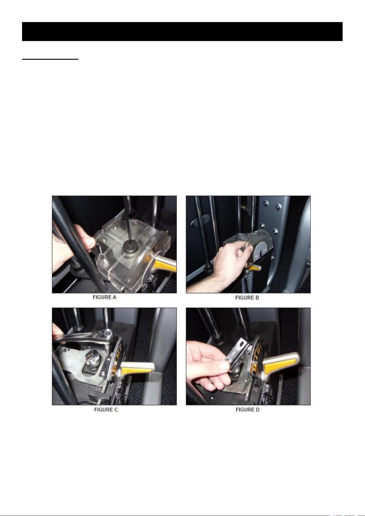
Doc No.
Revision
date
Edition
time
Page
65
ULTRA V2
SERVICE MANUAL
Approval
Review
Editor
Allen Sun
Allen Sun
Hans Kong
Page 2

1
CONTENTS
CHAPTER 1:SERIAL NUMBER LOCATION
CHAPTER 2:MAINTENANCE & SAFETY................................................................................................4
CHAPTER 3:TROUBLESHOOTING......................................................................................................... 6
3.1 The Repetition Display Is Blank Or Is Not Counting Movements.
3.2 Incremental Weight Pin Is Loose Or Feels Sloppy
3.3 Weight Stack Pin Will Not Go Into Some Or All Weight Plates
3.4 The Weight Stack Cable Is Falling Off A Pulley Or Cam
3.5 Repetition Magnet Has Fallen Off Or Is Missing
3.6 Adjustable Handle Does Not Move Easily
CHAPTER 4:PARTS REPLACEMENT...................................................................................................13
4.1 Testing The Unit
4.2 Top Cover
4.3 Repetition Counter
4.4 Side Cover
4.5 Repetition Sensor
4.6 Incremental Weight Pin
4.7 Weight Plate
4.8 Weight Stack Pulley
4.9 Connection Rod
4.10 Seat Grip
4.11 Guide Rod
4.12 Linear Bearing
CHAPTER 5:BY MODELS........................................................................................................................26
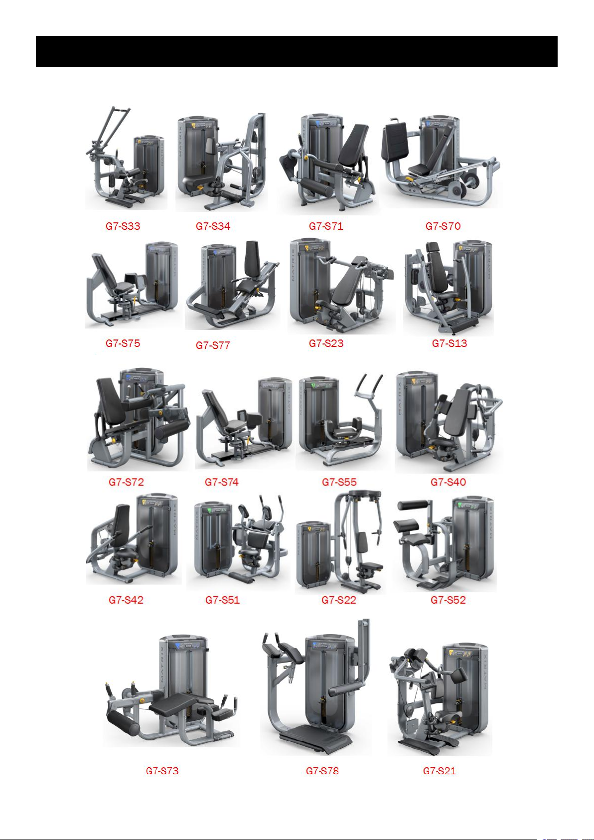
5.1 G7-S13-02
5.2 G7-S21-02
5.3 G7-S22
5.4 G7-S23-02
5.5 G7-S33-02
5.6 G7-S34-02
5.7 G7-S40-02
5.8 G7-S42-02
5.9 G7-S51-02
5.10 G7-S52-02
5.11 G7-S55-02
5.12 G7-S70-02
5.13 G7-S71-02
5.14 G7-S72-02
5.15 G7-S73-02
5.16 G7-S74-02 & G7-S75-02
5.17 G7-S77-02
5.18 G7-S78-02
.........................................................................................................................................
.............................................................................................................................................
..............................................................................................................................
.........................................................................................................................
.......................................................................................................................................
...........................................................................................................................
..................................................................................................................
....................................................................................................................................
.......................................................................................................................
..............................................................................................................................
........................................................................................................................................
......................................................................................................................................
...............................................................................................................................
.......................................................................................................................................
.......................................................................................................................................
.......................................................................................................................................
.......................................................................................................................................
.......................................................................................................................................
.......................................................................................................................................
.......................................................................................................................................
.......................................................................................................................................
.....................................................................................................................................
.....................................................................................................................................
.....................................................................................................................................
.....................................................................................................................................
.....................................................................................................................................
.....................................................................................................................................
.............................................................................................................
.....................................................................................................................................
.....................................................................................................................................
...........................................................................................
............................................
......................................................................
.................................................
..........................................................
........................................................................
..................................................................................
10
11
12
13
13
14
15
16
17
19
21
22
23
24
25
27
29
30
32
33
35
37
38
39
41
43
46
48
52
57
59
62
64
2
6
8
9
Page 3
2
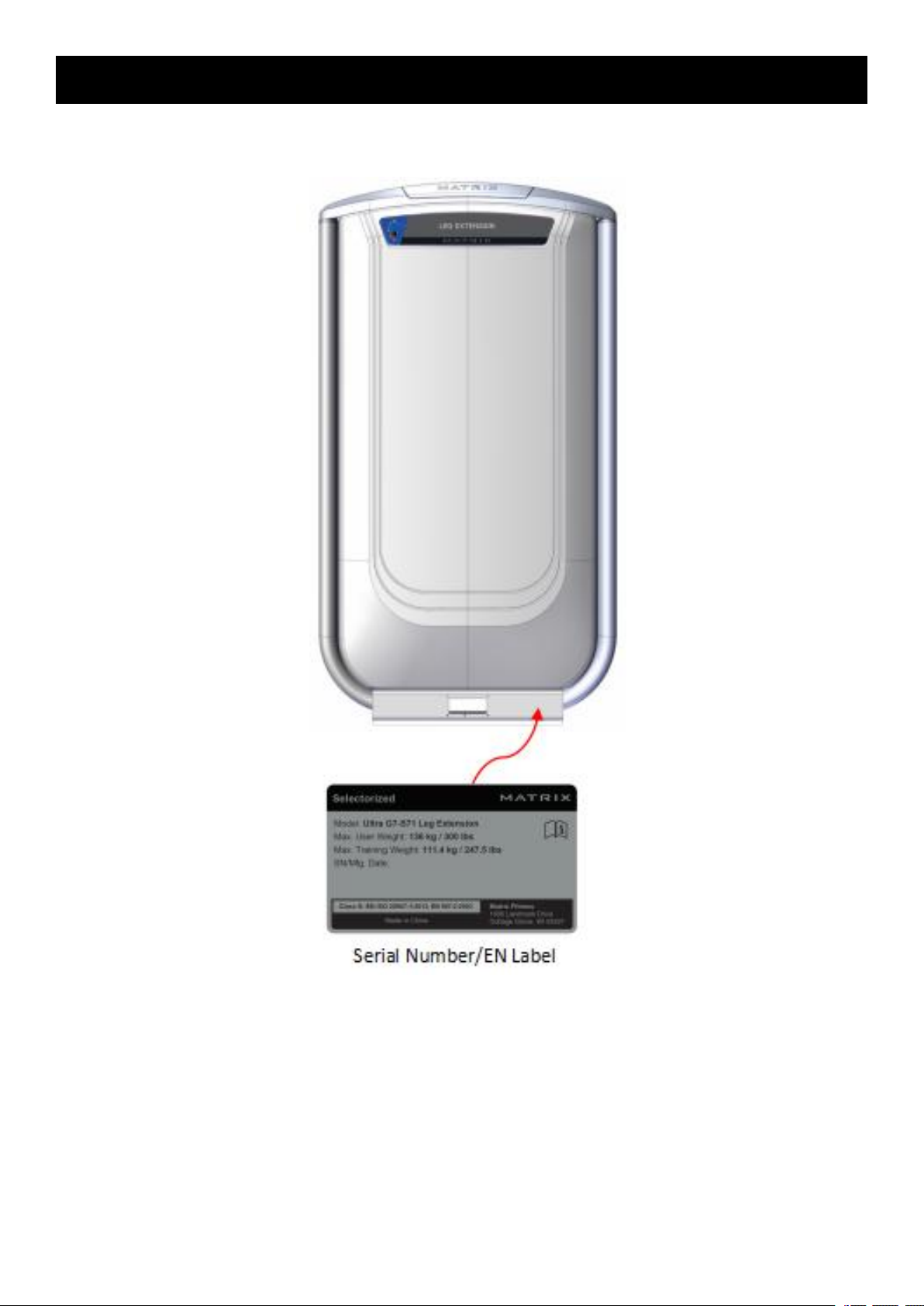
CHAPTER 1:SERIAL NUMBER LOCATION
Page 4
3
CHAPTER 1:SERIAL NUMBER LOCATION
Page 5

4
CHAPTER 2:MAINTENANCE & SAFETY
IMPORTANT SAFETY INFORMATION
It is the sole responsibility of the purchaser of MATRIX products to instruct all individuals, whether
they are the end user or supervising personnel on proper usage of the equipment.
It is recommended that all users of MATRIX exercise equipment be informed of the following
information prior to its use.
Do not use any equipment in any way other than designed or intended by the manufacturer. It is
imperative that MATRIX equipment be used properly to avoid injury.
INSTALLATION
STABLE AND LEVEL SURFACE: MATRIX exercise equipment must be installed on a stable base
and properly leveled.
SECURING EQUIPMENT: Manufacturer recommends that all stationary MATRIX strength
equipment be secured to the floor to stabilize equipment and eliminate rocking or tipping over. This
must be performed by a licensed contractor.
Under no circumstances should you slide equipment across the floor due to risk of tipping. Use
proper materials handling techniques and equipment recommended by OSHA. All anchor points
must be able to withstand 750 lbf. (3.3 kN) pull-out force.
MAINTENANCE
DO NOT use any equipment that is damaged and or has worn or broken parts. Use only
replacement parts supplied by your country’s local MATRIX dealer.
MAINTAIN LABELS AND NAMEPLATES: Do not remove labels for any reason. They contain
important information. If unreadable or missing, contact your MATRIX dealer for a replacement.
MAINTAIN ALL EQUIPMENT: Preventative maintenance is the key to smooth operating equipment
as well as keeping your liability to a minimum. Equipment needs to be inspected at regular
intervals.
Ensure that any person(s) making adjustments or performing maintenance or repair of any kind is
qualified to do so. MATRIX dealers will provide service and maintenance training at our corporate
facility upon request.
ADDITIONAL NOTES
This equipment should only be used in supervised areas where access and control is specifically
regulated by the owner. It is up to the owner to determine who is allowed access to this training
equipment. The owner should consider a user’s: degree of reliability, age, experience, etc.
This training equipment meets industry standards for stability when used for its intended purpose in
accordance with the instructions provided by the manufacturer.
This equipment is for indoor use only. This training equipment is a Class S product (designed for
use in a commercial environment such as a fitness facility). This training equipment is in
compliance with EN ISO 20957-1 and EN 957-2.
Page 6
5
CHAPTER 2:MAINTENANCE & SAFETY
1. Do not exceed weight limits of the exercise device.
2. If applicable, set safety stops to appropriate height.
3. If applicable, adjust seat pads, leg pads, foot pads, range of motion adjustment, or any other
4. Sit on bench (if applicable) and get into appropriate position for exercise.
5. Exercise using no more weight than you can safely lift and control.
6. In a controlled manner, perform exercise.
7. Return weight to its fully-supported start position.
TORQUE VALUES
M10 Bolt (Nyloc Nut & Flowdrill)
77 Nm / 57 lbf-ft
M8 Bolts
25 Nm / 18 lbf-ft
M8 Plastic
15 Nm / 11 lbf-ft
M6 Bolts
15 Nm / 11 lbf-ft
Pad Bolts
10 Nm / 7 lbf-ft
PROPER USAGE
type of adjustment mechanisms to a comfortable start position. Make certain that the adjusting
mechanism is fully engaged to prevent unintentional movement and to avoid injury.
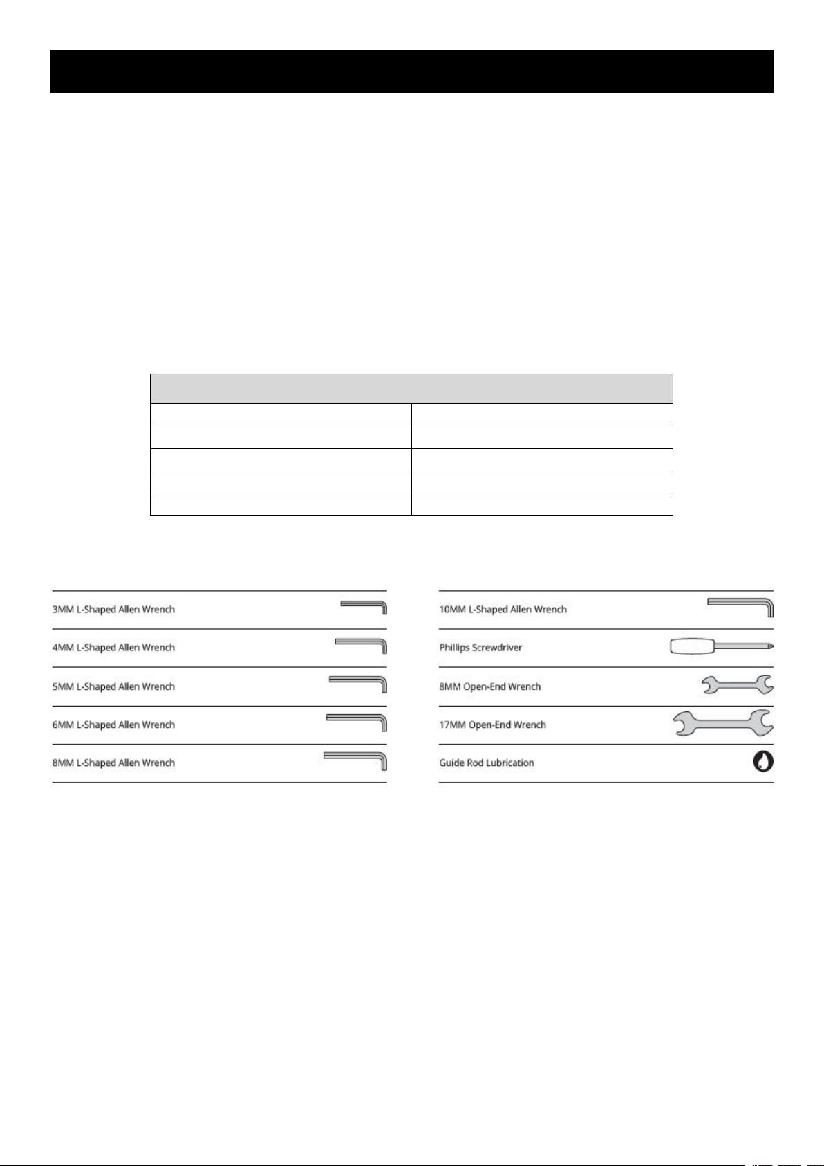
TORQUE VALUES
TOOLS REQUIRED FOR ASSEMBLY&MAINTENANCE (not included)
Page 7
6
CHAPTER 3:TROUBLESHOOTING
3.1 The Repetition Display Is Blank Or Is Not Counting Movements.
Possible Causes
1) The rep counter battery is dead or disconnected.
2) The rep counter is unplugged from the repetition sensors.
3) The magnet is missing or positioned incorrectly.
4) The repetition sensors are faulty or positioned incorrectly.
5) The rep counter is faulty.
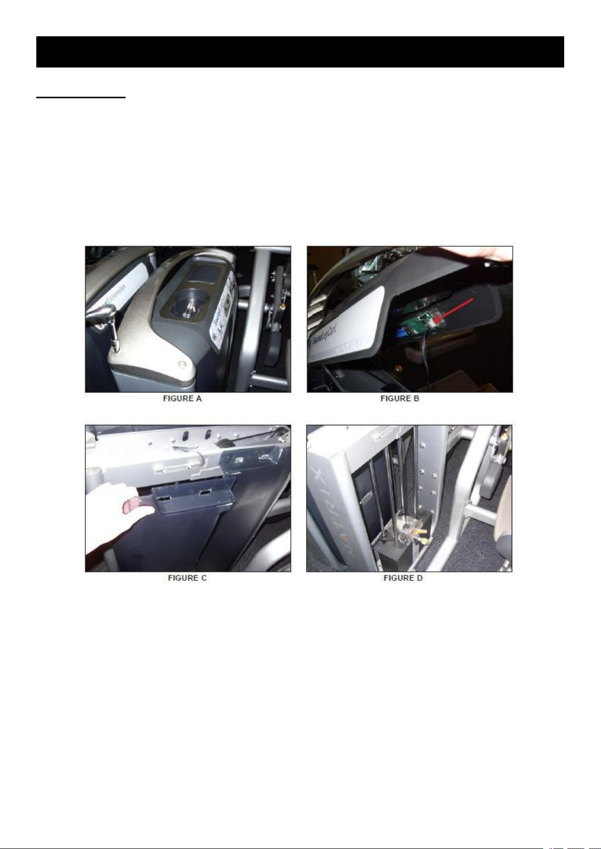
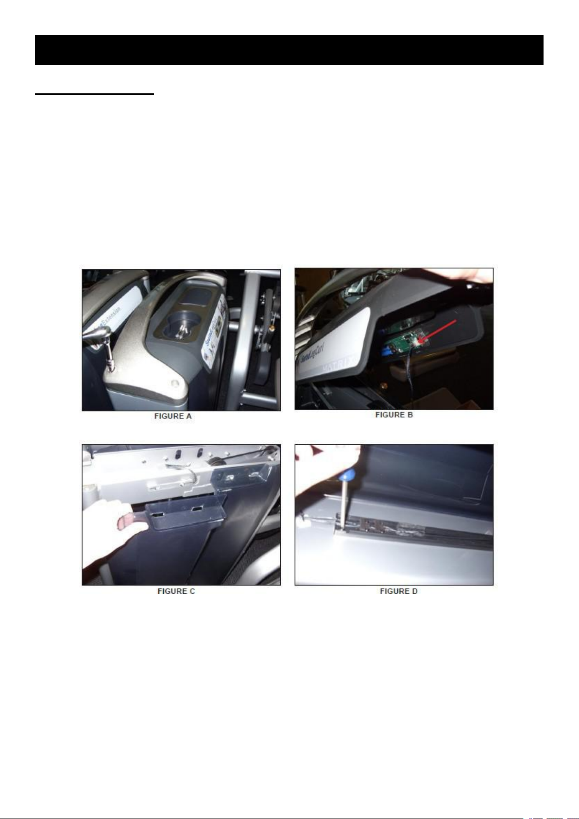
Solution
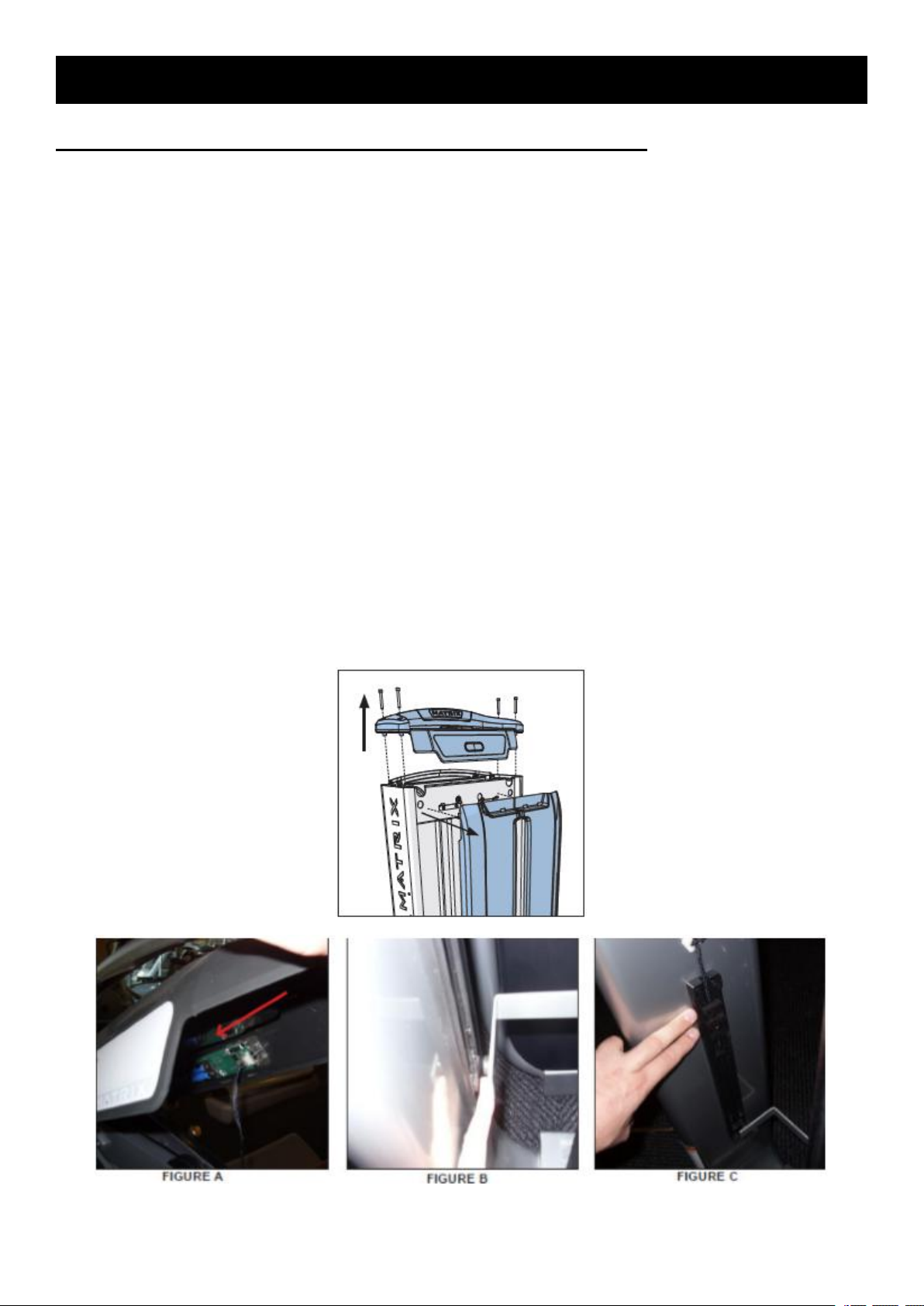
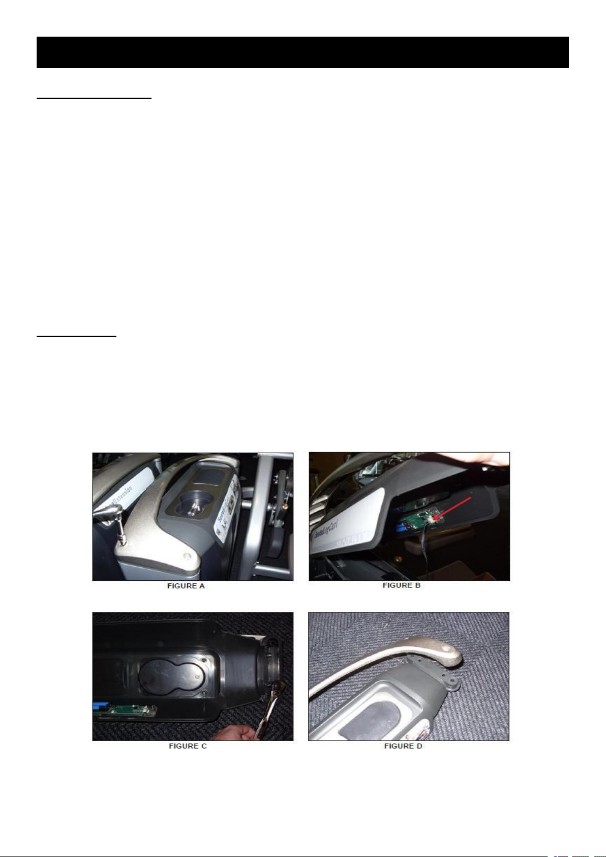
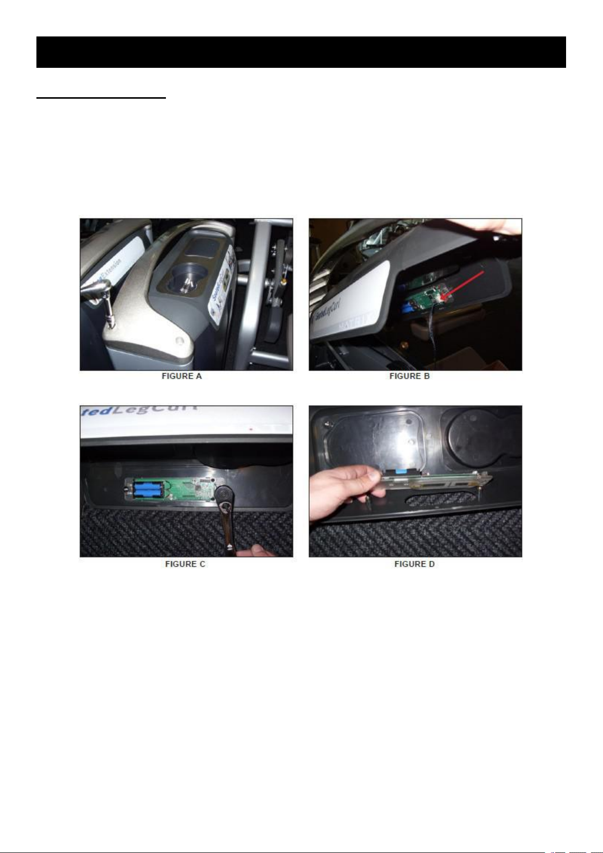
1) Remove the 4 screws holding on the aluminum wing and top cover. Check that the battery for
the rep counter is firmly seated and has a charge. Replace the battery if needed.
2) Check the connection of the wiring coming from the repetition sensors to the rep counter
(Figure A).
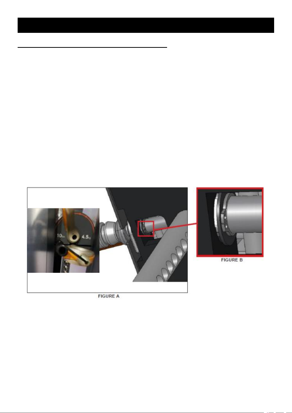
3) Check that the magnet is present and in a position to be read by the repetition sensors (Figure
B). The magnet should be slightly off the center of the sensors.
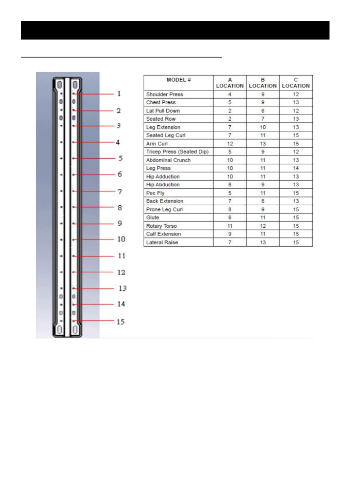
4) If the rep counter displays a value, but is not counting repetitions, check the position of the
sensors. The sensors should be positioned depending on the model according to the chart on the
following page. If the rep sensors are positioned correctly and still not reading, replace the
repetition sensors (Figure C).
5) If the repetition sensors and battery have been replaced and the issue is still present, replace
the rep counter.
Page 8
7
CHAPTER 3:TROUBLESHOOTING
3.1 The Repetition Is Blank Or Is Not Counting Movements.
Page 9
8
CHAPTER 3:TROUBLESHOOTING
1) Remove the weight stack covers.
3.2 Incremental Weight Pin Is Loose Or Feels Sloppy
Possible causes
1) The snap ring holding the incremental weight pin in position is damaged or missing.
2) The incremental weight pin is damaged.
Solution
a. Remove the 4 screws holding the clear plastic cover over the incremental weight pin and
remove the clear plastic cover.
b. Check the incremental weight pin for damage, replace if needed.
2) Check if the snap ring and washer holding the incremental weight pin to the stack is in place
(Figure A & B).
a. If this snap ring is missing, install a new snap ring.
b. If the snap ring is in place, but not holding the incremental weight pin in place, it may not be
properly installed in the groove in the pin.
c. If the snap ring is in place and properly installed in the groove, but the pin is still loose, replace
the snap ring (the ring may be too stretched out to be effective).
Page 10
9
CHAPTER 3:TROUBLESHOOTING
3.3 Weight Stack Pin Will Not Go Into Some Or All Weight Plates
Possible Causes
1) The weight stack pin is bent.
2) The cable is attached too loosely or too tightly.
3) The weight plates are not seated correctly at the bottom of the guide rods.
4) The top weight plate bushings are damaged.
Solution
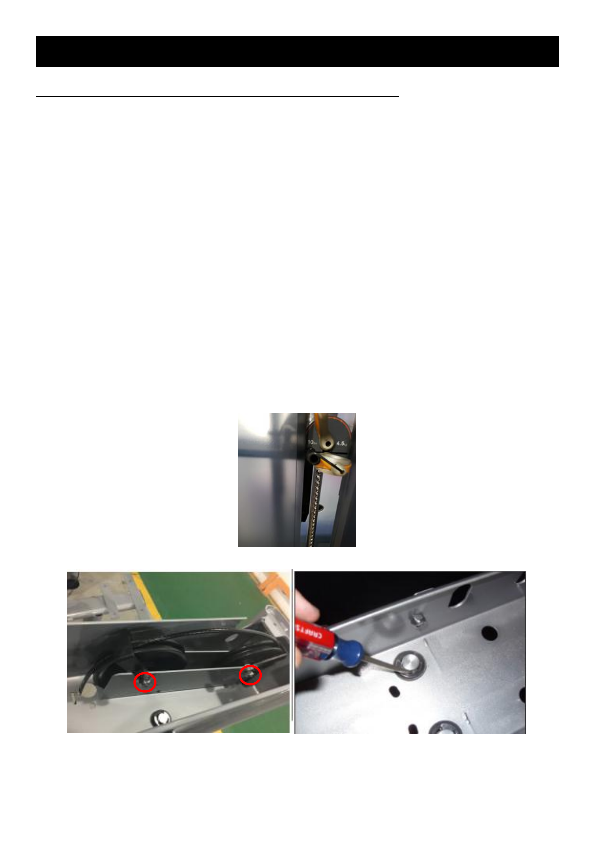
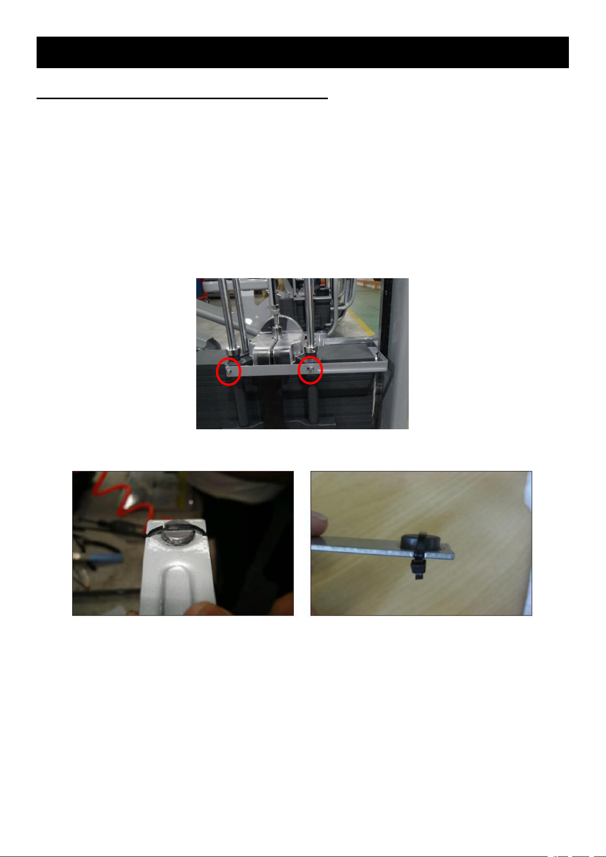
1) Check the weight stack pin for straightness. Replace if needed (Figure A).
2) Check the tightness of the cable. If the cable is too loose or too tight:
a. Remove the 4 screws holding down the aluminum wing and top cover. Detach the rep counter
wire and set aside the aluminum wing and top cover.
b. Loosen the 2 bolts holding the 2 pulleys in place at the top of the weight stack frame (Figure B).
NOTE: A short 8 mm Allen wrench may be needed for some models.
c. Rotate the 2 pulley assemblies to remove the slack from the cable, and then re-tighten the 2
pulley bolts.
3) Remove the clips holding the weight stack guide rods on the top frame (Figure C).
a. Lean the guide rods towards the unit frame and shake back and forth so that the weight plates
are seated at the bottom of the guide rods without any gap between plates.
4) Replace the top weight plate bushings.
Figure A
Figure B Figure C
Page 11
10
CHAPTER 3:TROUBLESHOOTING
3.4 The Weight Stack Cable Is Falling Off A Pulley Or Cam
Possible Causes
1) The cable is too loose or too tight.
2) The cable is routed incorrectly.
Solution
1) Check the tightness of the cable. Make sure that it is tensioned properly.
2) Check the routing of the cable through the weight stack.
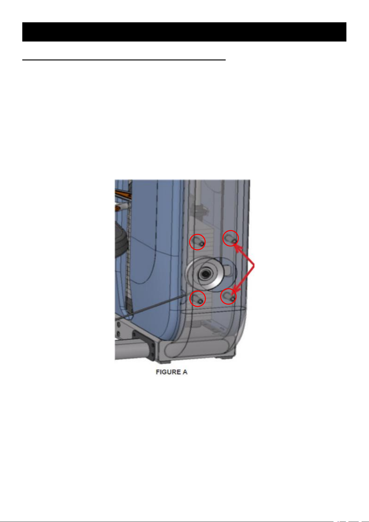
a. Make sure that the cable is not routed around a standoff in the weight stack frame (Figure A).
b. Follow the routing of the cable. The cable should be centered on pulleys and cams before
being tensioned.
Page 12
11
CHAPTER 3:TROUBLESHOOTING
1) Remove side covers and the 2 screws fixing the magnet frame (Figure A).
2) Install a zip tie to securely attach the magnet to the bracket (Figure B).
3) When installing the zip tie, make sure that the head of the zip tie is on the opposite side of the
3.5 Repetition Magnet Has Fallen Off Or Is Missing
Possible Causes
1) The repetition counter magnet was not secured tightly enough to the repetition counter bracket.
Solution
bracket from the magnet so that the head does not interfere with the movement of the top weight
plate (Figure C).
Figure A
Figure B Figure C
Page 13
12
CHAPTER 3:TROUBLESHOOTING
1) The pins are rubbing on the frame creating friction.
3.6 Adjustable Handle Does Not Move Easily
Possible causes
Solution
1) Remove the affected pin, add grease (Matrix recommends Super Lube brand grease with PTFE)
and then re-install the pin.
Page 14
13
CHAPTER 4:PARTS REPLACEMENT
1) Check that the weight stack pin will slide freely into the weight stack at all positions.
2) Check that the incremental weight pin is tight and moves freely.
3) Check that the cable is tight and properly routed.
4) Check that the seat moves freely and that the seat spring assists the user to move the seat into
5) Check all adjustment handles for function.
6) Check that the arms on the unit are even.
7) Check that the repetition counter is active and working properly.
4.1 Testing The Unit
Once the unit or replacement part is fully installed and assembled and properly placed on the floor,
use the following instructions to test the machine:
NOTE: Not all of the replacement instructions will apply to every model.
a higher position.
4.2 Top Cover
1) Remove the 4 screws going through the aluminum wing into the top cover of the weight stack
(Figure A).
2) Disconnect the repetition counter wire and remove the aluminum wing and top cover from the
weight stack (Figure B).
3) Remove the 4 screws attaching the aluminum wing to the top cover (Figure C).
4) Remove the aluminum wing from the top cover (Figure D).
5) Reverse Steps 1-4 to install a new top cover.
Page 15
14
CHAPTER 4:PARTS REPLACEMENT
4.3 Repetition Counter
1) Remove the 4 screws going through the aluminum wing into the top cover of the weight stack
(Figure A).
2) Disconnect the repetition counter wire and remove the aluminum wing and top cover from the
weight stack (Figure B).
3) Remove the 2 screws attaching the repetition counter to the top cover (Figure C).
4) Remove the repetition counter from the top cover (Figure D).
5) Reverse Steps 1-4 to install a new repetition counter.
Page 16
15
4.4 Side Cover
1) Remove the 4 screws going through the aluminum wing into the top cover of the weight stack
2) Disconnect the repetition counter wire and remove the aluminum wing and top cover from the
3) Pull up on each weight stack shroud and remove it from the weight stack frame (Figure C).
4) Figure D shows the weight stack with all 3 side covers removed.
5) Reverse Steps 1-3 to install new side covers.
(Figure A).
weight stack (Figure B).
CHAPTER 4:PARTS REPLACEMENT
Page 17
16
4.5 Repetition Sensor
1) Remove the 4 screws going through the aluminum wing into the top cover of the weight stack
2) Disconnect the repetition counter wire and remove the aluminum wing and top cover from the
3) Remove the side covers from the weight stack frame (Figure C).
4) Remove the 4 screws holding the repetition sensors to the weight stack frame (Figure D).
5) Remove the tie straps holding the repetition sensor wires in place, and remove the repetition
6) Reverse Steps 1-5 to install new repetition sensors.
(Figure A).
weight stack (Figure B).
sensors.
CHAPTER 4:PARTS REPLACEMENT
Page 18
17
CHAPTER 4:PARTS REPLACEMENT
1) Remove the side covers as outlined in Section 5.4.
2) Remove the 4 screws holding on the clear plastic cover over the incremental weight pin and
3) Remove the 2 screws holding on the reaction block and remove it (Figures C & D).
4) Remove the snap ring holding the incremental weight pin to the top weight plate and remove the
5) Reverse Steps 1-4 to install a new incremental weight pin.
4.6 Incremental Weight Pin
remove it (Figures A & B).
incremental weight pin (Figures E, F, & G).
Page 19
18
CHAPTER 4:PARTS REPLACEMENT
4.6 Incremental Weight Pin
Page 20
19
CHAPTER 4:PARTS REPLACEMENT
1) Remove the outside cover as outlined in Section 5.2&5.4.
2) Remove the 4 screws holding on the clear plastic cover over the incremental weight pin and
3) Remove the 2 screws holding on the reaction block and remove it (Figures C & D).
4) Move the rubber cover on the cable by pulling up on it (Figure E).
5) Turn the cable retainer counter clockwise until there is enough slack in the cable to remove it
6) Remove the incremental weight pin as outlined in Section 5.6.
7) Remove the snap ring from the top of the weight stack guide rods (Figure H).
8) Lean the guide rod and leave the fixing rack away from the weight stack.(Figure I).
9) Lean the weight stack towards the frame and remove the weight plates as needed (Figure J).
10) Reverse Steps 1-9 to install a new weight plate.
4.7 Weight Plate
remove it (Figures A & B).
(Figure F & G).
Page 21

20
4.7 weight plate
Figure H
CHAPTER 4:PARTS REPLACEMENT
Figure I Figure J
Page 22

21
CHAPTER 4:PARTS REPLACEMENT
1) Remove the side covers as outlined in Section 5.4.
2) Remove the 4 screws holding on the clear plastic cover over the incremental weight pin and
3) Move the rubber cover on the cable by pulling up on it (Figure A).
4) Turn the cable retainer counter clockwise until there is enough slack in the cable to remove it
5) Remove the 2 screws fix the weight stack pulley and remove it.(Figure D & F & E).
Figure F
Figure E
4.8 Weight Stack Pulley
remove it (see Section 5.6 for pictures).
(Figure B & C).
Page 23

22
CHAPTER 4:PARTS REPLACEMENT
4.9 Connection Rod
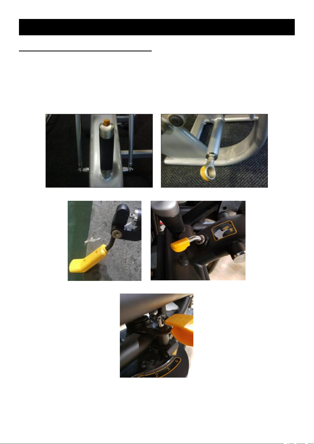
1) Remove the 2 screws going into the connecting rod (Figure A).
2) Remove the connecting rod (Figure B).
3) When installing a new connecting rod, make sure that the swirl spring is present and properly
installed (there should be at least 2 swirl springs for each set of 4 connecting rods) (Figures C & D).
Figure C Figure D
Page 24

23
CHAPTER 4:PARTS REPLACEMENT
4.10 Seat Grip
1) Loosen the lock nut on the seat adjustment handle by turning it clockwise (Figure A).
2) Remove the seat adjustment handle by turning it counter-clockwise (Figure B).
3) Reverse Steps 1-2 to install a new seat adjustment handle.
Figure A Figure B
Page 25

24
4.11 Guide Rod
1) Refer to section 4.2, 4.4, 4.7, 4.8 and remove outside covers,pulley,weight stack and weight
2) Remove bushings and blocks (Figure A).
3) Replace guide rods.
4) Reserve step 1-3 to recover the machine.
Blocks
Bushings
plate.
CHAPTER 4:PARTS REPLACEMENT
Figure A
Page 26

25
4.12 Linear Bearing
1) Remove the end of steel rope (Figure A).
2) Remove the nut and washer (Figure B).
3) Replace the linear bearing and recover the machine (Figure C).
CHAPTER 4:PARTS REPLACEMENT
Figure A Figure B
Figure C
Page 27

26
CHAPTER 5:BY MODELS
Page 28

27
5.1 G7-S13-02
1) Remove 4 screws under the seat on both sides to replace the seat pad(Figure A).
2) Remove upper 2 screws to replace the head pad (Figure B).
3) Remove lower 2 screws to replace the back pad (Figure B).
5.1.1 Head&Seat&Back& Pad
CHAPTER 5:BY MODELS
Figure A
Figure B
Page 29

28
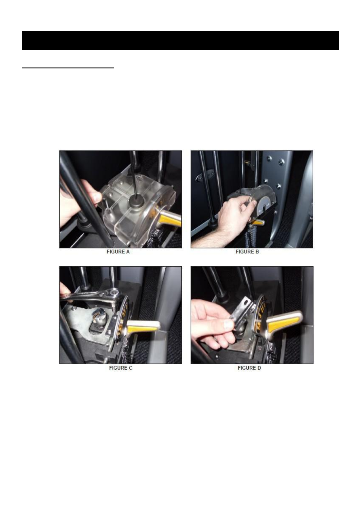
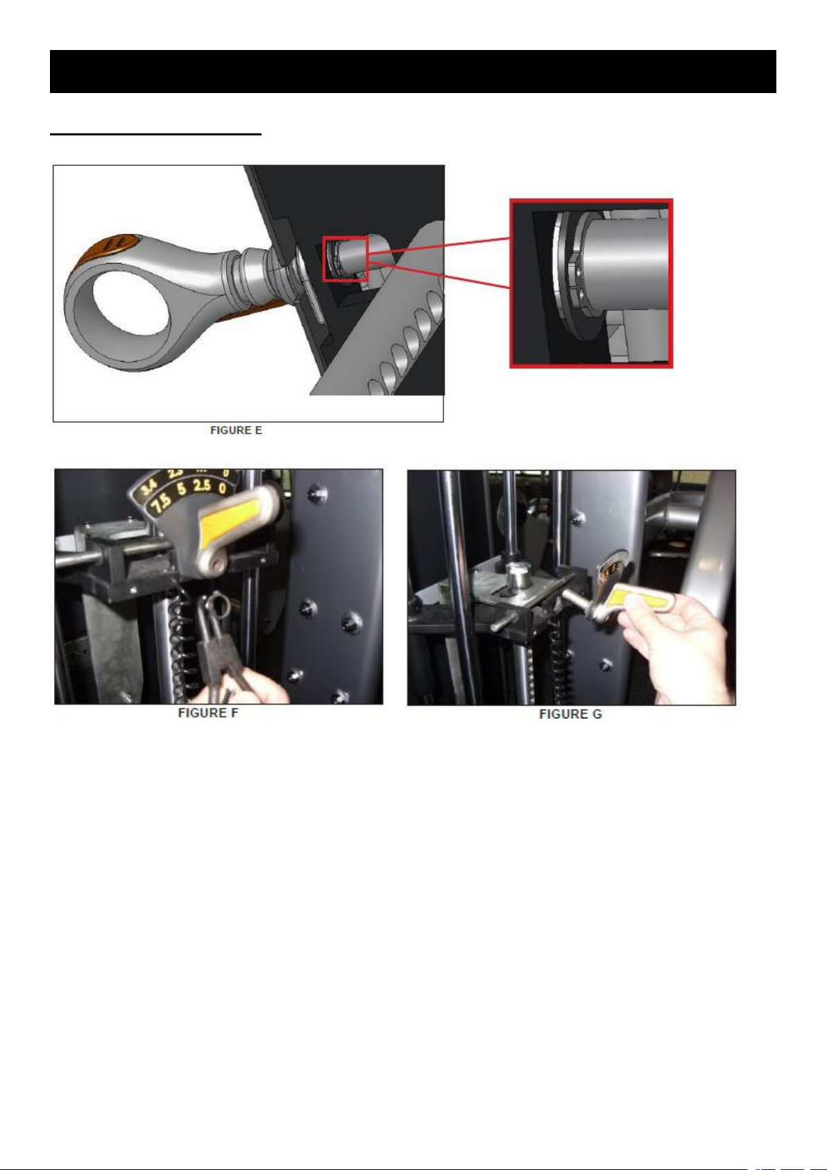
5.1 G7-S13-02
1) Remove the fixing screw and the connection plate (Figure A).
2) Remove the stopper block and remove the handle(Figure B).
3) Remove the chain and the stopper block (Figure C & D).
4) Remove the pull pin(Figure E).
5.1.2 Adjustable Handle
CHAPTER 5:BY MODELS
Figure A Figure B
Figure C Figure D
Figure
Page 30

29
5.2 G7-S21-02
1) Remove 4 screws under the seat on both sides to replace the seat pad (Figure A).
2) Remove 4l screws to replace the chest pad (Figure B).
3) Remove 3 screws to replace the arm pad (Figure C).
5.2.1 Seat&Chest&Arm Pad
CHAPTER 5:BY MODELS
Figure A
Figure B
Figure C
Page 31

30
5.3 G7-S22
4) Remove 3 screws under the seat to replace the seat pad (Figure A).
5) Remove 3 screws to replace the back pad (Figure B).
5.3.1 Seat&Back Pad
CHAPTER 5:BY MODELS
Figure A
Figure B
Page 32

31
5.3 G7-S22
1) Remove 3 screws with wrench and remove the iron plate (Figure A).
2) Remove the stopper plate (Figure B).
3) Hold the arm and remove the axle (Figure C).
4) Reserve Step 1-3 to install a new swing arm(Figure D).
5.3.2 Swing Arm
CHAPTER 5:BY MODELS
Figure A Figure B
Figure C Figure D
Page 33

32
5.4 G7-S23-02
1) Remove 4 screws under the seat on both sides to replace the seat pad (Figure A).
2) Remove upper screw to replace the head pad (Figure B).
3) Remove lower 2 screws to replace the back pad (Figure B).
5.4.1 Head&Seat&Back Pad
CHAPTER 5:BY MODELS
Figure A
Figure B
Page 34

33
5.5 G7-S33-02
1) Remove 4 screws under the seat on both sides to replace the seat pad (Figure A).
5.5.1 Seat Pad
CHAPTER 5:BY MODELS
Figure A
Page 35

34
5.5 G7-S33-02
1) Remove 3 screws on the fixing cover (Figure A).
2) Remove the grip (Figure B).
3) Pull out the pin (Figure C).
4) Apply grease and reserve step 1-3 to replace(Figure D).
5.5.2 Adjustable Handle
CHAPTER 5:BY MODELS
Figure A Figure B
Figure C Figure D
Page 36

35
5.6 G7-S34-02
1) Remove 4 screws under the seat on both sides to replace the seat pad (Figure A).
2) Remove 4 screws to remove the chest pad (Figure B).
5.6.1 Seat&Chest Pad
CHAPTER 5:BY MODELS
Figure A
Figure B
Page 37

36
5.6 G7-S34-02
1) Remove the handle, stopper block, spring and pull pin one by one (Figure A & B).
2) Reserve Step 1 to install a new pull pin with some Lubricating oil.
4
3
2
1
5.6.2 Adjustable Handle
CHAPTER 5:BY MODELS
Figure A Figure B
Page 38

37
5.7 G7-S40-02
1) Remove 4 screws under the seat on both sides to replace the seat pad (Figure A).
2) Remove all screws to replace the back pad (Figure B & C).
3) Remove 2 screws to replace the arm pad (Figure D).
5.7.1 Seat&Back&Arm Pad
CHAPTER 5:BY MODELS
Figure A
Figure B Figure C
Figure D
Page 39

38
5.8 G7-S42-02
1) Remove 4 screws under the seat on both sides to replace the seat pad (Figure A).
2) Remove 2 screws to replace the back pad (Figure B).
5.8.1 Seat&Back Pad
CHAPTER 5:BY MODELS
Figure A
Figure B
Page 40

39
CHAPTER 5:BY MODELS
1) The arm assembly does not have a spring properly installed (the spring is exposed when the
1) Install a spring into the arm assembly (the seat should have 2 springs, if it has 3, one of the
2) Add some Lubricating oil (Figure B).
5.9 G7-S51-02
5.9.1 Abdominal Arm Does Not Spring Back When Released
Possible causes:
right arm is removed).
Solution:
springs can be used)(Figure A).
Figure A
Figure B
Page 41

40
5.9 G7-S51-02
1) Remove 4 screws under the seat on both sides to replace the seat pad (Figure A).
2) Remove 4 screws to replace upper or lower back pad (Figure B & C).
3) Remove 4 screws to replace the arm pad (Figure D).
5.9.2 Seat&Back&Arm Pad
CHAPTER 5:BY MODELS
Figure A
Figure B Figure C
Figure D
Page 42

41
5.10 G7-S52-02
1) Remove 4 screws to replace the back pad (Figure A).
2) Remove 4 screws under the seat on both sides and replace it (Figure B).
5.10.1 Deck & Seat Pad
CHAPTER 5:BY MODELS
Figure A
Figure B
Page 43

42
5.10 G7-S52-02
1) Remove 3 screws on the fixing cover (Figure A).
2) Remove the grip (Figure B).
3) Pull out the pin (Figure C).
4) Apply grease and reserve step 1-3 to replace(Figure D).
5.10.2 Adjustable Handle
CHAPTER 5:BY MODELS
Figure A Figure B
Figure C Figure D
Page 44

43
CHAPTER 5:BY MODELS
1) The foam rubber was not properly installed on the arm frame.
5.11 G7-S55-02
5.11.1 Foam Rubber Rotates On The Handles
Possible Causes
Solution
1) Remove the existing foam rubber from the arm frame (Figure A).
2) Apply hairspray to the arm frame and the re-install the foam rubber. As it dries, the hairspray
should prevent the foam rubber from rotating (Figure B).
Figure A
Figure B
Page 45

44
5.11 G7-S55-02
1)
Remove 4 screws under the seat on both sides to replace the seat pad (Figure A).
2)
Remove 2 screws to replace the side pad (Figure B).
5.11.2 Seat&Side Pad
CHAPTER 5:BY MODELS
Figure A
Figure B
Page 46

45
5.11 G7-S55-02
1) Remove the snap ring and fix block (Figure A & B).
2) Remove the screw and the adjustable handle can be removed(Figure C & D).
3) Remove the pull pin(Figure E & F).
5.11.3 Adjustable Handle
CHAPTER 5:BY MODELS
Figure A Figure B
Figure C Figure D
Figure E Figure F
Page 47

46
CHAPTER 5:BY MODELS
1) Remove the upper 2 screws to replace the head pad(Figure A).
2) Remove the lower 2 screws to replace the back pad(Figure A).
3) Remove 4 screws under the seat pad on both sides to replace the pad(Figure B).
5.12 G7-S70-02
5.12.1 Head & Back & Seat Pad
Figure A
Figure B
Page 48

47
5.12 G7-S70-02
1) Remove the chain fixing handle(Figure A).
2) Remove the fixing screw and the handle(Figure B).
3) Remove the stopper ring(Figure C).
4) Add grease on the pull pin and reserve step 1-3 to replace(Figure D).
5.12.2 Adjustable Handle
CHAPTER 5:BY MODELS
Figure A Figure B
Figure C Figure D
Page 49

48
CHAPTER 5:BY MODELS
1) Remove the lower 2 screws to replace the back pad (Figure A).
2) Remove 4 screws under the seat on both sides to replace the seat pad (Figure B).
5.13 G7-S71-02
5.13.1 Head & Back & Seat Pad
Figure A
Figure B
Page 50

49
5.13 G7-S71-02
1) Remove 3 screws on the fixing cover (Figure A).
2) Remove the grip (Figure B).
3) Pull out the pin (Figure C).
4) Apply grease and reserve step 1-3 to replace(Figure D).
5.13.2 Adjustable Handle
CHAPTER 5:BY MODELS
Figure A Figure B
Figure C Figure D
Page 51

50
CHAPTER 5:BY MODELS
5) Remove the chain fixing handle (Figure A).
6) Remove the fixing screw and the handle (Figure B).
7) Remove the stopper ring (Figure C).
8) Add grease on the pull pin and reserve step 1-3 to replace(Figure D).
5.13 G7-S71-02
5.13.3 Adjustable Handle - Continue
Figure A Figure B
Figure C Figure D
Page 52

51
CHAPTER 5:BY MODELS
1) Move the back pad to the position furthest to the front of the unit - this will remove most of the
2) Remove the 2 screws holding on the connecting rod and remove it (Figure B & C).
3) Reverse Steps 1-3 to install a new connecting rod.
5.13 G7-S71-02
5.13.4 Connection Rod
tension on the connecting rod springs (Figure A).
NOTE 1: When installing a new connecting rod, it will usually be necessary to remove the front
connecting rod to install the rear one.
NOTE 2: When installing a new connecting rod, make sure that the swirl spring is present and
properly installed (there should be at least 3 swirl springs for each set of 4 large connecting rods)
(Figures D & E).
NOTE 3: If replacing the right front connecting rod, be sure to re-install the ROM plate (Figure F).
Figure A Figure B
Figure C Figure D
Figure E Figure F
Page 53

52
CHAPTER 5:BY MODELS
1) Remove the lower 2 screws to replace the back pad (Figure A).
2) Remove 4 screws under the seat on both sides to replace the seat pad (Figure B).
5.14 G7-S72-02
5.14.1 Head & Back & Seat Pad
Figure A
Figure B
Page 54

53
5.14 G7-S72-02
1) Remove 3 screws on the fixing cover (Figure A).
2) Remove the grip (Figure B).
3) Pull out the pin (Figure C).
4) Apply grease and reserve step 1-3 to replace(Figure D).
5.14.2 Adjustable Handle
CHAPTER 5:BY MODELS
Figure A Figure B
Figure C Figure D
Page 55

54
CHAPTER 5:BY MODELS
5) Remove the chain fixing handle (Figure A).
6) Remove the fixing screw and the handle (Figure B).
7) Remove the stopper ring (Figure C).
8) Add grease on the pull pin and reserve step 1-3 to replace(Figure D).
5.14 G7-S72-02
5.14.2 Adjustable Handle - Continue
Figure A Figure B
Figure C Figure D
Page 56

55
CHAPTER 5:BY MODELS
9) Remove the screw holding the arm adjustment handle to the frame from the back side (Figure
10) Pull the arm adjustment handle out of the frame (Figure B).
11)
Reverse Steps 1-3 to install a new arm adjustment handle.
5.14 G7-S72-02
5.14.2 Adjustable Handle - Continue
A).
Figure A
Figure B
Page 57

56
CHAPTER 5:BY MODELS
1) Move the back pad to the position furthest to the front of the unit - this will remove most of the
2) Remove the 2 screws holding on the connecting rod and remove it(Figure B & C).
3) Reverse Steps 1-3 to install a new connecting rod.
5.14 G7-S72-02
5.14.3 Connection Rod
tension on the connecting rod springs (Figure A).
NOTE 1: When installing a new connecting rod, it will usually be necessary to remove the front
connecting rod to install the rear one.
NOTE 2: When installing a new connecting rod, make sure that the swirl spring is present and
properly installed (there should be at least 3 swirl springs for each set of 4 large connecting rods)
(Figures D & E).
NOTE 3: If replacing the right front connecting rod, be sure to re-install the ROM plate (Figure F).
Figure A Figure B
Figure C Figure D
Figure E Figure F
Page 58

57
5.15 G7-S73-02
1) Remove all screws to replace the deck pad (Figure A & B ).
2) Remove 3 screws under the arm pad and replace it (Figure C & D ).
5.15.1 Deck & Arm Pad
CHAPTER 5:BY MODELS
Figure A Figure B
Figure C Figure D
Page 59

58
5.15 G7-S73-02
1) Remove 3 screws on the fixing cover (Figure A).
2) Remove the grip (Figure B).
3) Pull out the pin (Figure C).
4) Apply grease and reserve step 1-3 to replace(Figure D).
5.15.2 Adjustable Handle
CHAPTER 5:BY MODELS
Figure A Figure B
Figure C Figure D
Page 60

59
5.16 G7-S74-02 & G7-S75-02
1) Remove the 2 screws to replace the back pad (Figure A&B).
2) Remove the 4 screws to replace the seat pad (Figure C).
3) Remove 4 screws to replace the leg pad (Figure D).
5.16.1 Back & Seat & Leg Pad
CHAPTER 5:BY MODELS
Figure A Figure B
Figure C
Figure D
Page 61

60
5.16 G7-S74-02 & G7-S75-02
1) Remove the chain and the screw (Figure A).
2) Remove the handle (Figure B).
3) Remove the stopper block (Figure C).
4) Add grease on the pull pin and reserve step 1-3 to replace(Figure D).
5.16.2 Adjustable Handle
CHAPTER 5:BY MODELS
Figure A Figure B
Figure C Figure D
Page 62

61
CHAPTER 5:BY MODELS
5) Remove the handle (Figure A&B).
6) Remove the stopper block (Figure C).
7) Remove the pull pin(Figure D).
5.16 G7-S74-02 & G7-S75-02
5.16.2 Adjustable Handle - Continue
Figure A Figure B
Figure C
Figure D
Page 63

62
5.17 G7-S77-02
1) Remove the 2 screws to replace the back pad (Figure A).
2) Remove 4 screws under the seat pad on both sides to replace the pad (Figure B).
5.17.1 Back & Seat Pad
CHAPTER 5:BY MODELS
Figure A
Figure B
Page 64

63
5.17 G7-S77-02
1) Remove the chain fixing handle (Figure A).
2) Remove the fixing screw and the handle (Figure B).
3) Remove the stopper ring (Figure C).
4) Add grease on the pull pin and reserve step 1-3 to replace(Figure D).
5.17.2 Adjustable Handle
CHAPTER 5:BY MODELS
Figure A Figure B
Figure C Figure D
Page 65

64
5.18 G7-S78-02
1) Remove the 3 screws to replace the arm pad (Figure A).
2) Remove 4 screws under the chest pad and replace it (Figure B).
5.18.1 Arm & Chest Pad
CHAPTER 5:BY MODELS
Figure A
Figure B
Page 66

65
5.18 G7-S78-02
1) Remove the fixing screw (Figure A).
2) Remove the chest pad mast (Figure B & C).
3) Remove the handle (Figure D).
4) Push the pin out of the hole (Figure E).
5) Add grease on the pull pin and reserve step 1-4 to replace.
5.18.2 Adjustable Handle
CHAPTER 5:BY MODELS
Figure A Figure B
Figure C Figure D
Figure E
 Loading...