

Page 1
Assembly Guide
G3 Seat Post Revision
Page 2

Table Of Contents
Safety, General Care & Maintenence.........................................................3
Parts List..............................................................................................................4
Installation & Assembly
Bushings to Sleeve................................................................................5
Bushing/Sleeve Assembly to Frame...............................................6
Torsion Springs to Handle..................................................................7
Pawl to Handle.......................................................................................8
Front Cover to Frame.........................................................................10
Securing Bushing/Sleeve Assembly to Frame..........................11
Top Cover and Seat Post..................................................................12
Limit Pin.................................................................................................13
Page 3

IMPORTANT SAFETY INSTRUCTIONS
IMPORTANT SAFETY INFORMATION
It is the sole responsibility of the purchaser of Matrix products to instruct all individuals, whether they are the end user or
supervising personnel on proper usage of the equipment.
It is recommended that all users of Matrix exercise equipment be informed of the following information prior to its use.
PROPER USAGE
Do not use any equipment in any way other than designed or intended by the manufacturer. It is imperative that Matrix
equipment be used properly to avoid injury.
Keep hands and feet clear at all times from moving parts to avoid injury.
CHECK FOR DAMAGED PARTS
1. DO NOT use any equipment that is damaged and or has worn or broken parts. Use only replacement parts supplied by
your country’s local Matrix dealer.
2. MAINTAIN LABELS AND NAMEPLATES: Do not remove labels for any reason. They contain important information.
If unreadable or missing, contact your Matrix dealer for a replacement.
3. SECURING EQUIPMENT: All equipment MUST be secured to the oor to stabilize and eliminate rocking or tipping over.
This must be performed by a licensed contractor.
4. MAINTAIN ALL EQUIPMENT: Preventative maintenance is the key to smooth operating equipment as well as keeping
your liability to a minimum. Equipment needs to be inspected at regular intervals.
5. Ensure that any person(s) making adjustments or performing maintenance or repair of any kind is qualied to do so.
Matrix dealers will provide service and maintenance training at our corporate facility upon request.
WARNING: SERIOUS INJURY CAN OCCUR ON THIS EQUIPMENT. FOLLOW
THESE PRECAUTIONS TO AVOID INJURY!
1. Never allow children on strength equipment. Teenagers must be supervised at all times while using
this equipment.
2. All warnings and instructions should be read and proper instruction obtained prior to use.
3. Cease exercise if you feel faint or dizzy. Obtain a medical exam before beginning an exercise program
4. Keep body, hair, clothing and accessories free and clear of all moving parts.
5. Inspect the machine before use. DO NOT use machine if it appears damaged or inoperable.
6. This equipment should only be used in supervised areas where access and control are regulated by the owner.
3
Page 4
UPDATED G3 SEAT KIT
12
6
5
2
1
4
3
14
13715
8
9
10
11
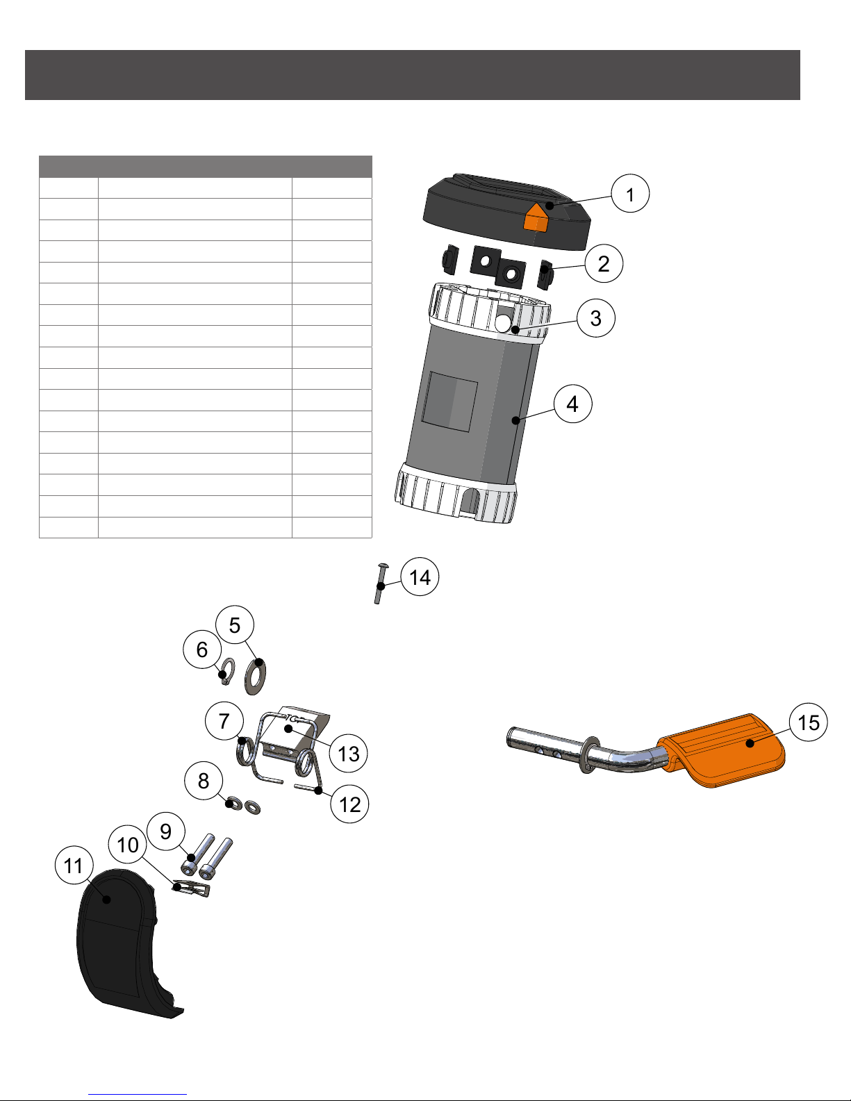
ID DESCRIPTION QUANITY
1 Rubber Cap 1
2 M8 Square Nut 4
3 Bushing 2
4 Sleeve 1
5 22 mm OD Washer 2
6 12 mm Snap Ring 2
7 Left Torsion Spring 1
8 M5 Flat Washer 2
9 M5 X 25L SHC 2
10 Clip Nut 1
11 Cover 1
12 Right Torsion Spring 1
13 Pawl 1
14 Screw 1
15 Handle 1
16 M8 X 12L SHC (Not Shown) 4
17 M8 Washer (Not Shown) 4
Parts List
SEAT KIT EXPLODED
4
Page 5
ASSEMBLY
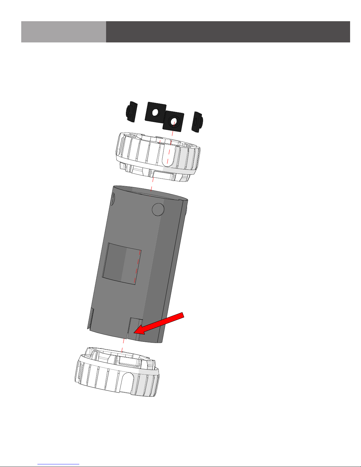
STEP 1: BUSHING/SLEEVE ASSEMBLY
Step 1: Assemble two bushings (#3) onto sleeve (#4).
Bend four tabs in to secure bushing
(#3) onto sleeve (#4)
5
Page 6

ASSEMBLY
STEP 2: BUSHING ASSEMBLY
Step 2: Assemble bushing assembly into frame tube.
M8 Square nuts must be
at top of assembly
6
Page 7

Step 3: Assemble springs onto handle.
Springs must be
oriented as shown
ASSEMBLY
STEP 3: HANDLE ASSEMBLY
Assemble one snap ring and
washer to handle shaft before
assembling onto frame
7
Page 8

Step 4: Assemble pawl onto handle shaft.
Assemble the pawl underneath the springs. Reach
your hand inside the
bushings to support the
pawl while bolting it to
the handle shaft.
ASSEMBLY
STEP 4: PAWL ASSEMBLY
8
NOTE: The text “TOP”
must be positioned as
shown
Page 9

Step 4: Assemble pawl onto handle shaft.
ASSEMBLY
STEP 4: PAWL ASSEMBLY
Be sure to use blue Locktite 242 or equivalent
threadlocker on M5 X 25L screws that are included.
9
Page 10

Step 5: Assemble cover onto frame.
1. Assemble Push-nut onto cover.
ASSEMBLY
STEP 5: COVER ASSEMBLY
10
2. Assemble cover to
frame. Insert bottom
edge of cover then
rotate up as shown.
Secure cover with
screw.
Page 11

ASSEMBLY
STEP 6: BUSHING/SLEEVE ASSEMBLY
Step 6: Secure bushing/sleeve assembly to tube.
1. Secure bushing assembly
to frame tube as shown
using (4) M8 X 12L screws
and washers into the M8
square nuts.
FRONT
2. Torque two rear screws
to 13 N-m/115 in-lbs.
Torque two front screws
less than rear screws.
Be sure to use blue Locktite 242
or equivalent threadlocker if
bolts do not have blue patches
11
Page 12

Step 7: Assemble cover and seat post.
ASSEMBLY
STEP 7: SEAT POST ASSEMBLY
1. Assemble rubber cap.
2. Rotate handle up to stop and
then assemble seat post.
12
Page 13

Step 8: Assemble Limit Pin.
ASSEMBLY
STEP 8: LIMIT PIN ASSEMBLY
13
Page 14

Matrix Fitness
1600 Landmark Drive
Cottage Grove WI 53527
matrixtness.com
Toll-free 866.693.4863
Facsimilie 608.839.8687
G3 Seat Post Revision 1.1 Copyright© 2011 Matrix Fitness
 Loading...