

Page 1

G1-GM30 3-STACK
MULTI-GYM (GM167D)
STRENGTH
SERVICE MANUAL
1
Page 2

TABLE OF CONTENTS
CHAPTER 1: SERIAL NUMBER LOCATION …………………………..…… 3
CHAPTER 2: ASSEMBLY INSTRUCTIONS
2.1 G1MG30 3-Stack Multi-Gym Assembly Instructions...............................................4
CHAPTER 3: TROUBLESHOOTING
3.1 Troubleshooting - Cable issue ………………………………………………….….. …..13
CHAPTER 4: PART REPLACEMENT INSTRUCTIONS
4.1 Hand Grip Foam Replacement.............................................................................14
4.2 Seat Pad Replacement.........................................................................................15
4.3 Back Pad Replacement........................................................................................17
4.4 Round Pad Replacement.....................................................................................18
4.5 Seat Pad Adjustment Handle Replacement.........................................................20
4.6 Back Pad Adjustment Handle Replacement.........................................................20
4.7 Round Pad Adjustment Handle Replacement......................................................21
4.8 Arm Pad Adjustment Handle Replacement..........................................................21
4.9 Seat Sleeve Replacement....................................................................................22
2
Page 3

CHAPTER 1: SERIAL NUMBER
LOCATION
1.1 SERIAL NUMBER LOCATION
The serial number is located at the bottom of the weight stack frame.
3
Page 4
CHAPTER
2
: ASSEMBLY INSTRUCTIONS
2.1 G1-MG30 3-STACK MULTI-GYM ASSEMBLY INSTRUCTIONS
UNPACKING G1MG30 3-Stack Multi-Gym
Thank you for purchasing a MATRIX Fitness product. This machine is an EN957-1 and EN957-2
complaint Class S product. Your
MATRIX G1MG30 3-Stack Multi-Gym is inspected before it is packaged. It is shipped in multiple
pieces to facilitate the compact packaging of the machine. Prior to assembly, confirm all the
components by matching them with the exploded diagrams. The weight stack is shipped in separate
packaging to reduce the weight of this box. Carefully unpack the unit from this box and dispose of the
packing materials in accordance with your local laws.
CAUTION
The weight of the G1MG30 3-Stack Multi-Gym is 704 lbs (320 kg) not including the weight stacks.
The weight stack tower is packaged completely assembled for ease of installation; use extra caution
when removing from its pallet during assembly. The weight stack for this machine is 3 x 200 lbs. (3 x
91 kg). To avoid injury to yourself and prevent damage to the frame components, be sure to have
proper assistance removing the frame pieces from this box. Please be sure to install the equipment
on a stable base, properly level the machine and leave at least two feet of clearance to enter and exit
the machine. Maximum user weight for this machine is 350 lbs. (159 kg).
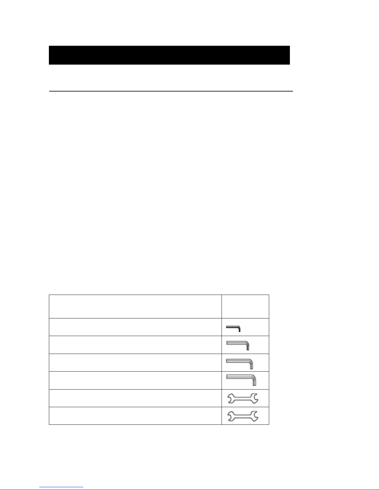
INCLUDE TOOLS REQUIRED FOR ASSEMBLY
3MM L-Shaped Allen Wrench
6MM L-Shaped Allen Wrench
8MM L-Shaped Allen Wrench
10MM L-Shaped Allen Wrench
13MM and 17MM Open-End Wrench
19MM Open-End Wrench
4
Page 5
THE STANDARD OF THE SCREW TORQUE
NO Nom Diameter Torque (kg/cm) Torque (lbs/in)
1 M4 28 24
2 M5 57 49
3 M6 97 84
4 M8 332 288
5 M10 789 684
6 M12 1380 1197
7 M14 2190 1901
8 M16 3420 2968
9 M18 4700 4079
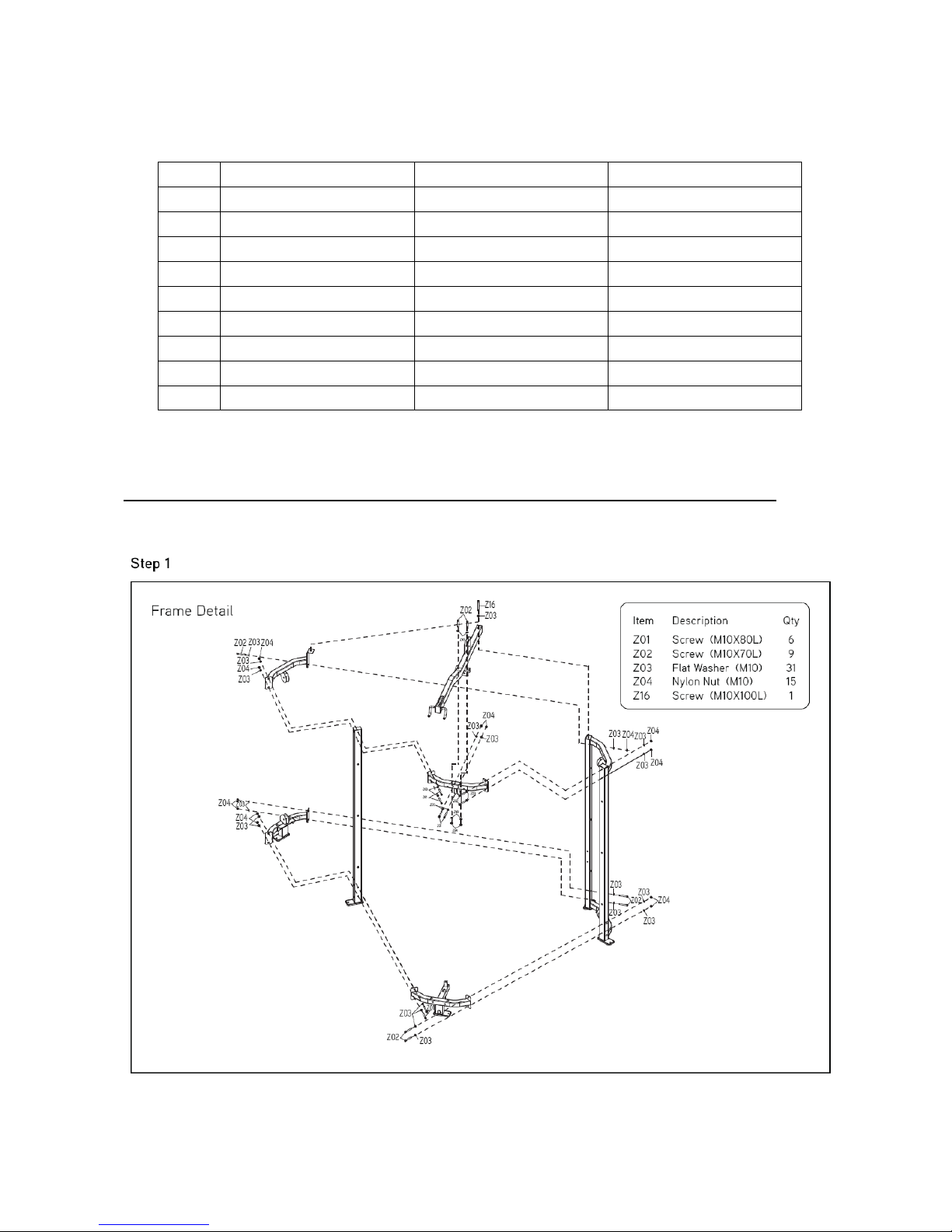
2.1 G1-MG30 3-STACK MULTI-GYM ASSEMBLY INSTRUCTIONS - CONTINUED
5
Page 6
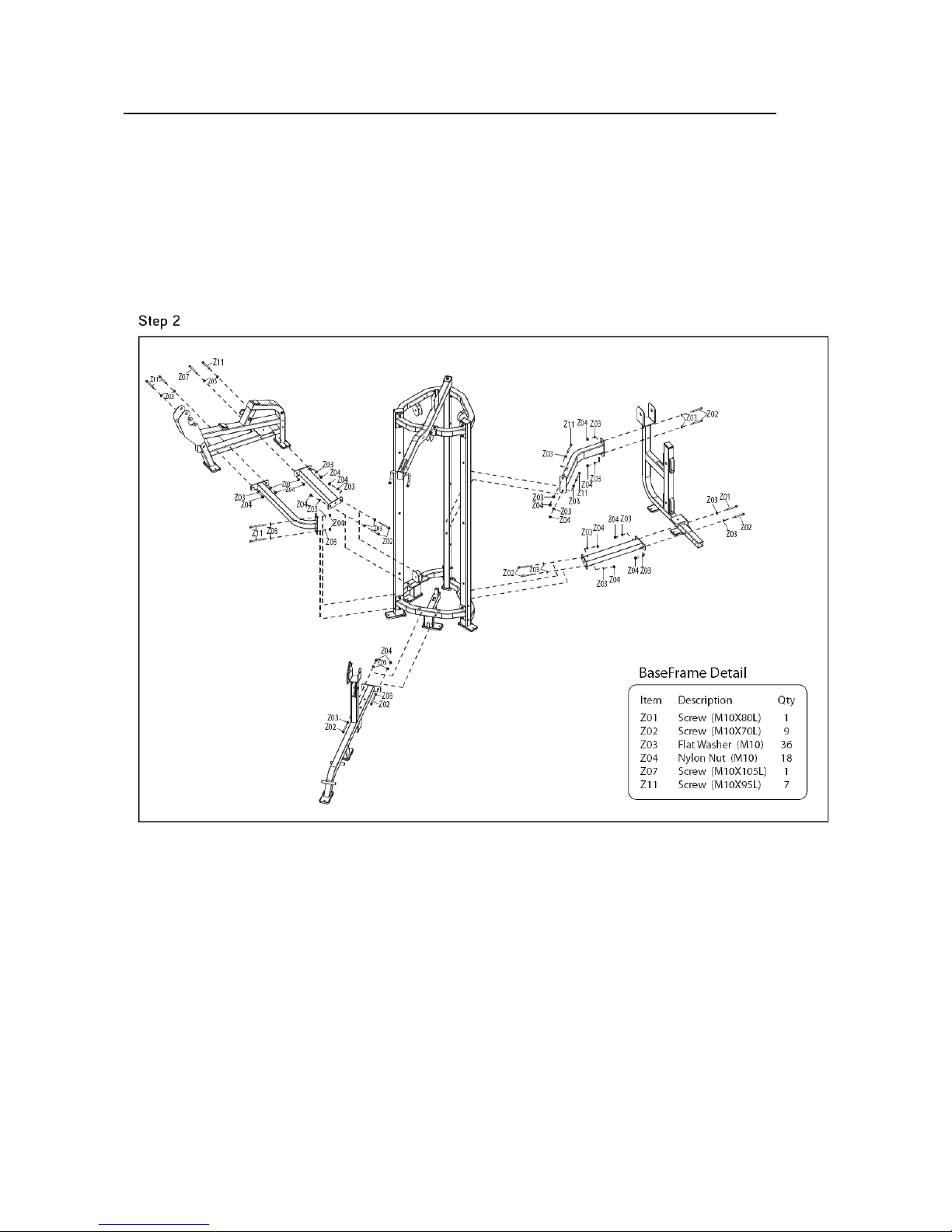
2.1 G1-MG30 3-STACK MULTI-GYM ASSEMBLY INSTRUCTIONS - CONTINUED
6
Page 7

2.1 G1-MG30 3-STACK MULTI-GYM ASSEMBLY INSTRUCTIONS - CONTINUED
7
Page 8

2.1 G1-MG30 3-STACK MULTI-GYM ASSEMBLY INSTRUCTIONS - CONTINUED
8
Page 9

2.1 G1-MG30 3-STACK MULTI-GYM ASSEMBLY INSTRUCTIONS - CONTINUED
9
Page 10

2.1 G1-MG30 3-STACK MULTI-GYM ASSEMBLY INSTRUCTIONS - CONTINUED
10
Page 11

2.1 G1-MG30 3-STACK MULTI-GYM ASSEMBLY INSTRUCTIONS - CONTINUED
11
Page 12

2.1 G1-MG30 3-STACK MULTI-GYM ASSEMBLY INSTRUCTIONS - CONTINUED
12
Page 13

CHAPTER
3
: TROUBLESHOOTING
3.1 TROUBLESHOOTING – CABLE ISSUES
CABLE IS LOOSE
POSSIBLE CAUSES
1. The fix bolts are loosed.
SOLUTION
1. Undo the former fixing nut , then the cable screw should be adjust fronted.(Figure A & B).
2. Lock the fixing nut (Figure C).
Figure A
Figure C
Figure B
13
Page 14

CHAPTER
4
: PART REPLACEMENT INSTRUCTIONS
4.1 HAND GRIP FOAM REPLACEMENT
1) To loose the screws of end cap of handlebar (Figure A).
2) To take off the end cap and cut off the original foam (Figure B).
3) Using tape to seal up the handlebar tube to avoid the oil or suds into the tube (Figure C).
4) To bent and hold the end of foam then put oil or suds into the inside of foam (Figure D).
5) Push the foam to tube (Figure E).
6) Take off the tape and fix the end cap (Figure F)
Figure A Figure B
Figure C Figure D
Figure E Figure F
14
Page 15

4.2 SEAT PAD REPLACEMENT
1) Use an 8MM L-Shaped Allen Wrench to take off 4 bolts from the old seat pad (Figure A)
2) Replace new pad and fix the 4 bolts (Figure B).
Figure A Figure B
1) Use an 8MM L-Shaped Allen Wrench to take off 4 bolts from the old seat pad (Figure A)
2) Replace new pad and fix the 4 bolts (Figure B).
Figure A Figure B
15
Page 16

1) Use an 8MM L-Shaped Allen Wrench to take off 4 bolts from the old seat pad (Figure A)
2) Replace new pad and fix the 4 bolts (Figure B).
Figure A Figure B
16
Page 17

4.3 BACK PAD REPLACEMENT
1) Use an 8MM L-Shaped Allen Wrench to take off 4 bolts from the old seat pad (Figure A)
2) Replace new pad and fix the 4 bolts (Figure B).
Figure A Figure B
1) Use an 8MM L-Shaped Allen Wrench to take off 4 bolts from the old seat pad (Figure A)
2) Replace new pad and fix the 4 bolts (Figure B).
Figure A Figure B
17
Page 18

4.4 ROUND PAD ADJUSTMENT PIN REPLACEMENT
1) Remove the C ring with C ring pliers (Figure A).
2) Remove the round end cover and the round sleeve (Figure B).
3) Install the new round pad, and set the round end cover and round sleeve, then put the round pad
onto the fixing tube (Figures C & D).
4) Set the C ring back into place with C ring pliers (Figure E).
Figure A Figure B
Figure C Figure D
Figure E Figure F
18
Page 19

1) Use an 8MM L-Shaped Allen Wrench to take off bolts from the old seat pad (Figure A)
2) Take out the boltsand disc plastic interior. (Figure B).
3) Remove the old round pad. (Figure C).
4) Replace the new round pad, then assemble the disc plastic interior and fix the bolt with
L-Shaped Allen Wrench(Figure D)
Figure A Figure B
Figure C Figure D
19
Page 20

4.5 SEAT ADJUSTMENT HANDLE REPLACEMENT
1) Use a 24MM Open-Ended Wrench to take off the old adjustment pin set (Figure A).
2) Install a new adjustment pin (Figure B).
Figure A Figure B
4.6 BACK ADJUSTMENT HANDLE REPLACEMENT
1) Use a 24MM Open-Ended Wrench to take off the old adjustment pin set (Figure A).
2) Install a new adjustment pin (Figure B).
Figure A Figure B
20
Page 21

4.7 ROUND ADJUSTMENT HANDLE REPLACEMENT
1) Using hand to take off the old adjustment pin set (Figure A).
2) Replace new adjustment pin and fix it (Figure B).
Figure A Figure B
4.8 ARM ADJUSTMENT HANDLE REPLACEMENT
1) Use a 24MM Open-Ended Wrench to take off the old adjustment pin set (Figure A).
2) Install a new adjustment pin (Figure B).
Figure A Figure B
21
Page 22

4.9 SEAT SLEEVE REPLACEMENT
1) Loose the screw (Figure A).
2) Tack out the seat (Figure B).
3) Take off the sleeve and then take off the tube bushing (Figure C).
4) Push the tube bushing into the sleeve (Figure C).
5) Fix the screws (Figure D ).
Figure A Figure B
Figure C Figure D
22
 Loading...