

Page 1
COSEC ARGO
COSEC ARGO FOE212/FOM212/FOI212
Quick Installation Guide
Know Your COSEC ARGO
What Your Package Contains
COSEC ARGO Variants
Assigning IP Address and Other Network Settings
Preparation For Installation
Technical Specification
Installation Instruction - Wall Mounting
Installation Instruction - Flush Mounting
Connecting The Cables
Please read this guide first for correct installation and
retain it for future reference. The information in this guide
has been authenticated at the time of publication.
However, Matrix Comsec reserves the right to make
changes in product design and specifications without
prior notice.
3
7
7
7
8
9
11
17
23
2
Page 2
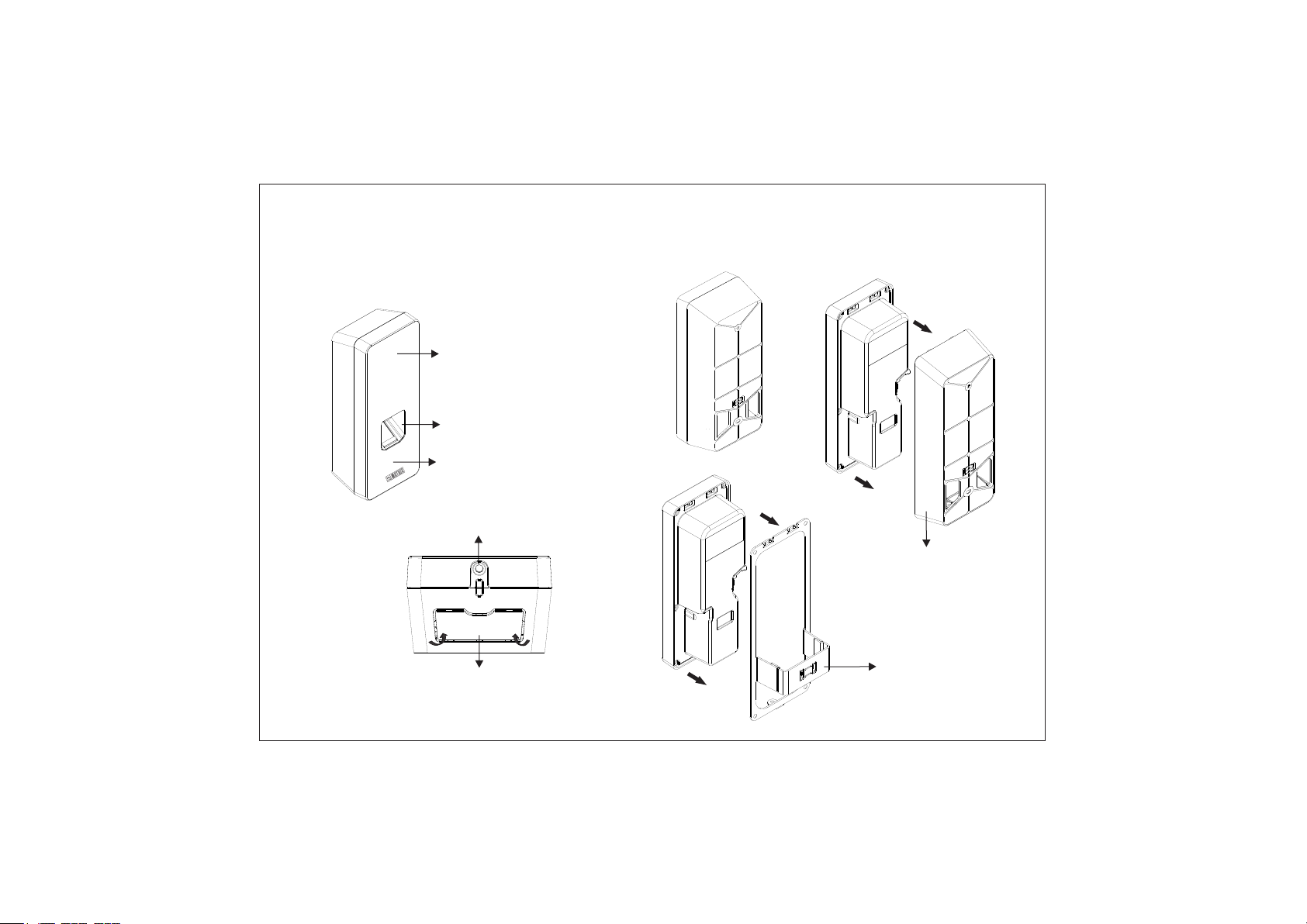
Know Your COSEC ARGO
Figure 1: Front View
Touch Screen
Display
Finger Sensor
Card Sensing
Area
Mounting
Screw Hole
Figure 2:
Bottom View
Knock Out Area
Figure 3: Rear View
Back Plate or
Wall Mounting Plate
Flush Mounting Plate
3
4
Page 3
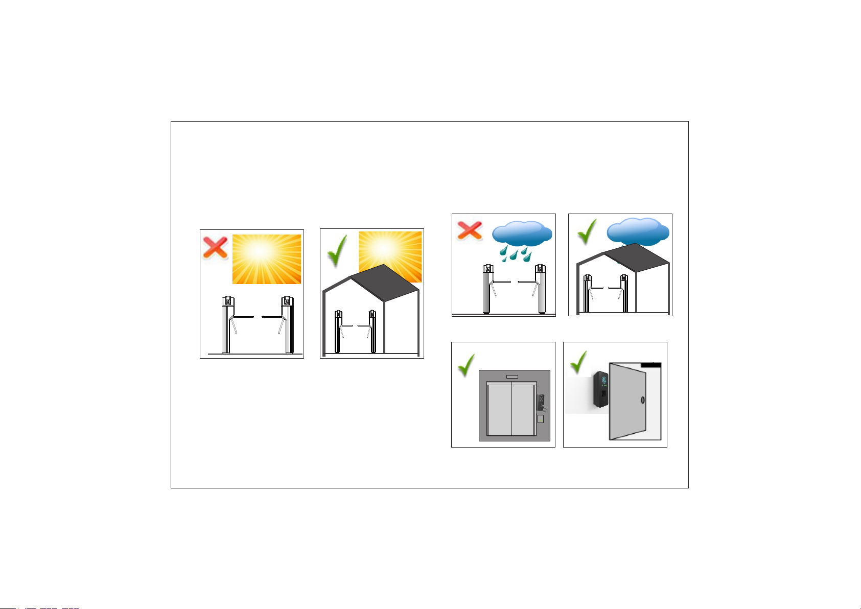
Pre-Installation Safety Instruction
1. Do not install the device in extremely hot temperature or under direct
Sunlight on turnstile or at extra bright places. This may affect the LCD
and finger print sensor of device. You can do indoor installation or on the
turnstile under the roof as shown in Figure4.
Figure 4
5. Do not install the device in outdoor areas which may be exposed
to rain, cold and dust. You can do indoor installation or on the turnstile
under the roof as shown in Figure5.
Figure 5
Figure 6
2. You can mount the device on a flat surface such as a wall or Elevator,
close to the access point (door) with surface wiring or concealed wiring
as shown in Figure6.
3. Recommended height from ground level is upto 4.5 feet.
4. Do not install on unstable surfaces, near volatile inflammable materials,
areas where volatile gas is created, where ferromagnetic field or noise is
induced, where static is created, such as desks made of plastics, carpets.
5
2
Next
Level
6
Page 4
What your Package contains
Ÿ COSEC ARGO Unit
Ÿ Flush Mounting Plate
Ÿ 4 Screws M5/25
Ÿ 4 Screw Grips
Ÿ Overswing Diode
Ÿ Power Adaptor 12VDC,2A
Ÿ Power Supply Cable (with DC Jack)
Ÿ EM Lock Cable
Ÿ External Reader Cable
Ÿ Flush Mounting Template
COSEC ARGO Variants
There are three different variants of COSEC ARGO depends upon the RFID
Card inserted in it.
COSEC ARGO Variants: FOE 212, FOM 212 and FOI 212
Assigning IP Address and Other Network Settings
Ÿ Open the Web browser in your computer.
Ÿ Enter the IP address of the COSEC ARGO (default: http://192.168.50.1)
in the address bar of the browser and press the Enter key on your
computer keyboard.
Ÿ When prompted, enter the login credentials for the Door.
Default Username: Admin
Default Password: 1234
Preparation for Installation
Before Wall mounting and Flush mounting of COSEC ARGO; follow the
below steps.
Ÿ Remove the mounting screw from mounting screw hole from the
bottom of device as shown in Figure2. The screw will be required
to fix the device at the end of Wall mounting or Flush mounting.
Ÿ Slide the back plate downwards to unlock the device from the
mounting hook and then remove it by pulling it outwards. This back
plate will be required as Wall mounting plate for Wall mounting of
COSEC ARGO. For details see Installation Instructions for Wall
Mounting.
Ÿ The flush mounting plate is available in the package. This plate
will be required for flush mounting of COSEC ARGO. For details
see Installation Instructions for Flush Mounting.
Wall Mounting: Select a location. It must be a flat surface such as wall,
close to the access point (door).
Flush mounting: Select a wooden door, or a location where the duct
can be made. The rectangular duct of has to made in the wooden doorsize
in which Flush mounting plate will be installed.
For Concealed wiring in Wall mounting/Flush mounting, first draw out
the sufficient length of the cables from the hole of the mounting plate.
For Non-concealed wiring in Wall mounting; the knock -out area
has to be removed from outside by pressing on the bottom duct as shown
in Figure2.
The connection of EM Lock must be done using the diode for Back
EMF protection.
7
8
Page 5
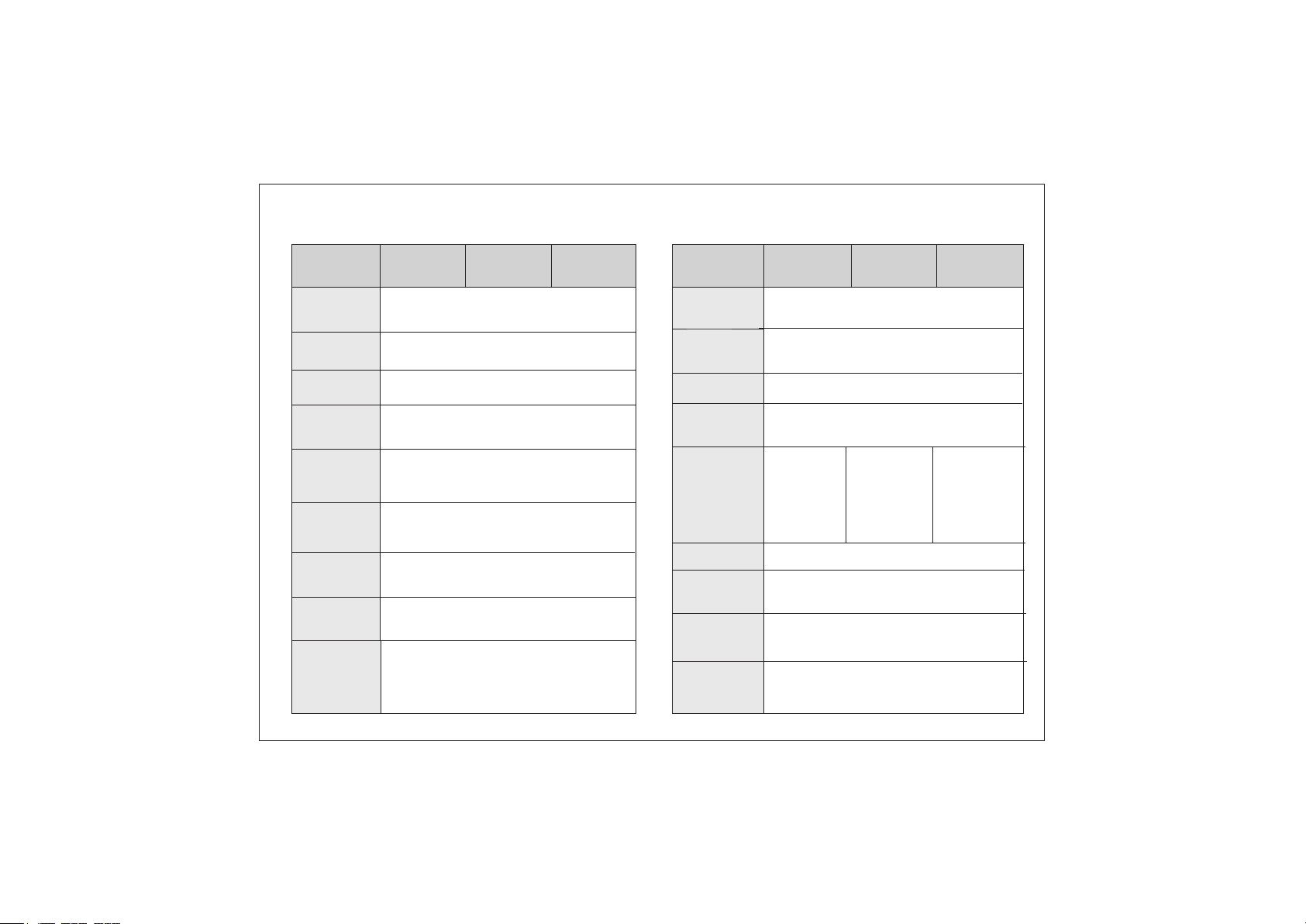
Technical Specification
Specification
Credential
Support
Event Buffer
Input Power
Reader Power
Output
Reader Interface
Type
Door Lock
Relay
Door Lock
Power
Built In PoE
Display
COSEC ARGO
FOE212
Internal 12V DC @0.5A in PoE supply
mode and 12V DC @1A in adapter
3.5 inch Capacitive IPS touch screen
with Gorilla glass 3.0;
Resolution: 480x320 pixels (HVGA)
COSEC ARGO
FOM212
Card, Pin and Finger
5,00,000
12V DC @2A and PoE
Max 12V DC @0.250 A
RS 232 and Wiegand
Max 30V DC @2A
PoE (IEEE 802.3 af)
COSEC ARGO
FOI212
Specification
User
Capacity
Communication
Port
Built In WiFi
Built In
Bluetooth
RF Option
(Card)
Thermal Sensor
Operating
Temperature
Dimensions
(H x W x D)
Weight
COSEC ARGO
FOE212
EM Prox
186mm x 74mm x 50mm (Wall Mount)
186mm x 74mm x 16mm (Flush Mount)
0.650 Kg (Product Only)
1.3 Kg (Product with Accessories)
COSEC ARGO
FOM212
50,000
Ethernet and WiFi
Yes (IEEE 802.11 b/g/n)
Yes
Mifare,
Desfire and
NFC
Yes
0 °C to +50 °C
COSEC ARGO
FOI212
HID I Class,
HID Prox,
EM Prox,
Desfire, NFC &
Mifare
9
10
Page 6

Installation Instruction - Wall Mounting
Step 1
Place the Wall Mounting plate and trace screw
holes 1 and 2 on the wall where the device is to
be installed.
1
2
Step 2
Drill the screw holes along the traced markings.
Fix Wall Mounting plate with the supplied screws.
Tighten the screws with screw driver.
11
12
Page 7

Step 3
Connect the cables of the ARGO unit and lead all the cables
through the duct of the Wall mounting plate into the electrical
box recessed in the wall i.e. concealed wiring or through
the bottom of the device in non-concealed wiring.
Duct for Concealed
Wiring
Ÿ Keep all the cables parallel to the side of the COSEC
ARGO body in such a way that it should not cover the
back of the body as illustrated in below figure.
Ÿ Radially curved all the cables and lead it through the
duct of wall mounting plate to fit the wall mounting
plate easily with COSEC ARGO.
13
Cable
Connectors
Mounting
Slots
Knock Out Area
for Non-Concealed Wiring
14
Page 8

Step 4
Align COSEC ARGO on the mounting plate and hook
into the mounting slot. Press the bottom side inwards
to lock it in place.
Step 5
Insert the mounting screw into the mounting screw
hole at the bottom of the device. Tighten the screw to
complete the Wall mounting.
Mounting
Screw
15
16
Page 9

Installation Instruction - Flush Mounting
Step 1
Ÿ Place the Flush Mounting Template on the desired
installation surface.
Ÿ Mark the area along the dotted line and trace the
four screw holes (say A,B,C,D) on the wall as
shown in Figure7.
Ÿ Now drill the dotted line area and four screw
holes (say A,B,C,D) on the wall as illustrated in
Figure8.
A
C
Figure 7
17
B
Flush Mounting
Template
D
Figure 8
Step 2
Place and fix Flush Mounting plate with the supplied screws.
Tighten the screws with screw driver.
Flush Mounting
Plate
B
A
D
C
18
Page 10

Step 3
Connect the cables of the ARGO unit and lead all the cables
through the flush mounting plate into the electrical box
recessed in the wall.
Mounting
Slots
Ÿ Keep all the cables parallel to the side of the COSEC
ARGO body in such a way that it should not cover the
back of the body as illustrated in below figure.
Ÿ Radially curved all the cables and lead it through the
duct of flush mounting plate to fit the flush mounting
plate easily with COSEC ARGO.
Mounting
Screw hole
19
Cable
Connectors
20
Page 11

Step 4
Align COSEC ARGO on the mounting plate and hook into the
mounting slot. Press the bottom side inwards to lock it in
place.
Step 5
Insert the mounting screw into the mounting screw
hole at the bottom of the device. Tighten the screw to
complete the Flush mounting.
Mounting
Screw
21
22
Page 12

Connecting the Cables
Ÿ For Concealed wiring; first draw out sufficient length of the
cables from the hole you have cut on the mounting surface.
Ÿ Make the electrical connections of Power, External Reader
and EM Lock by connecting supplied cable assembly to the
20 pin connector on the back side of COSEC ARGO.
Ÿ Connect the Ethernet Cable to the LAN port.
Ÿ Connect the micro USB port to Printer or Broadband dongle
using micro USB cable extender as required.
External Reader
CN1
Power
GND- Black
1
2
+12VDC IN- Red
CN2
1
DATA 0- Green
2
DATA 1- White
BEEPER- Yellow
3
GREEN LED- Orange
4
GND- Black
5
RS 232 RX- Pink
6
+12V RDR- Red
7
8
RS 232 TX- Grey
EM Lock Cable
External Reader Cable
(8 Pin to 15 Pin connector)
Diode
EM Lock
Power
Cable
CN3
Black
GND-
1
GND- Black
2
3
GND LOCK
EXIT SWITCH
4
+12V LOCK
5
6
GND
-
Black
7
L
OCK RL
DOOR STA
8
9
L
OCK RL
10
LOCK RLY COM -
F
G
Ethernet Cable
-
Black
-White
- Red
Y NO -Yellow
TUS-
Y NC
-
Dark Blue
Micro USB
connector cable
White
Light Brown
23
24
Page 13

Diode connection for Back EMF Protection
Power
GND
+
-
Cathode
Anode
EM
Lock
Reverse biased
Diode
Connect the Overswing diode in reverse biased condition
parallel to the EM Lock for a better contact lifetime and
to protect the Device from the Inductive kickback.
Disposal Of Product After End-Of-Life
WEEE Directive 2002/96/EC
The product refered is covered by the waste Electrical
and Electronic Equipment (WEEE) directive and must be
disposed of in a responsible manner.
At the end of product life cycle; batteries, soldered
boards, metal components and plastic components must
be disposed through recyclers.
If you are unable to dispose-off the products or unable to
locate e-waste recyclers, you may return the products to
Matrix Return Material Authorization (RMA) department.
25
26
Page 14

Copyright
All rights reserved. No part of this document may be
copied or reproduced in any form or by any means
without the prior written consent of Matrix Comsec.
Warranty
Limited Warranty. Valid only if primary protection is
provided, mains supply is within limit and protected, and
environment conditions are maintained within product
specifications. Complete warranty statement is available
on our website:
www.matrixaccesscontrol.com
MATRIX COMSEC
Head Office
394-GIDC, Makarpura, Vadodara - 390010, India
Ph: (+91)1800-258-7747
Email: Support@MatrixComSec.com
Website: www.matrixaccesscontrol.com
V.1, March ‘19
27
 Loading...