

Page 1

ETERNITY NE
Quick Start
Page 2

Page 3

ETERNITY NE
The Next Generation IP PBX for Small Businesses
Quick Start
Page 4

Disclaimer
Matrix Comsec reserves the right to change the product design, specifications,
components, product information and operating instructions, without prior notice.
This is a general documentation for all models/configurations of the product. The
product may not support some of the features/facilities described in this document.
Matrix Comsec makes no warranties with respect to this documentation and
disclaims any implied warranties. While every reasonable effort has been made to
ensure accuracy of content in this document, Matrix Comsec assumes no
responsibility for errors or omissions in this document. No liability is assumed for
damages, costs, expenses resulting from unauthorised modifications or repairs to
the product, and failure to use information or to comply with the installation,
operation and maintenance instructions contained in this document.
Copyright
All rights reserved. No part of this document may be copied or reproduced in any
form or by any means without the prior written consent of Matrix Comsec.
Version 1
Release date: February 19, 2011
Page 5

Contents
Know Your ETERNITY NE ............................................................................. 1
ETERNITY NE Overview ................................................................................... 1
Ports and Connectors .................................................................................. 2
LED .............................................................................................................. 2
Installing ETERNITY NE ................................................................................. 3
Preparing for Installation ................................................................................... 3
Selecting the Site .............................................................................................. 4
Getting Started .................................................................................................. 4
Package Contents ....................................................................................... 4
Installing Optional Modules ............................................................................... 5
GSM/UMTS Module ..................................................................................... 5
VoIP Module ................................................................................................ 5
Voice Mail System Module .......................................................................... 6
Door Phone Module ..................................................................................... 6
Connecting to Trunks ........................................................................................ 7
CO Trunks (Analog two-wire Trunks) .......................................................... 7
Mobile Networks .......................................................................................... 7
VoIP Network ............................................................................................... 9
Connecting Extensions .................................................................................... 11
Single Line Telephones (SLT) ................................................................... 11
Connecting Digital Key Phones (DKP) ...................................................... 11
Connecting SIP Extensions ....................................................................... 13
Setting up the Voice Mail System .................................................................... 22
Connecting Door Phone and Door Lock .......................................................... 22
Powering on ETERNITY NE ............................................................................ 24
Reset Cycle ............................................................................................... 24
How to access Jeeves ................................................................................. 25
Connecting a Computer .................................................................................. 25
Basic Configuration ..................................................................................... 29
Using the Wizard ............................................................................................. 29
Using Selective Configuration ......................................................................... 30
Table of Contents i
Page 6

Activating License Key .................................................................................... 31
ii Table of Contents
Page 7
Know Your ETERNITY NE
Thank you for choosing the Matrix ETERNITY NE! Please read the instructions in
this Quick Start to install and operate this feature-rich IP PBX. This is a common
Quick Start for all configurations of ETERNITY NE. For the purpose of illustration,
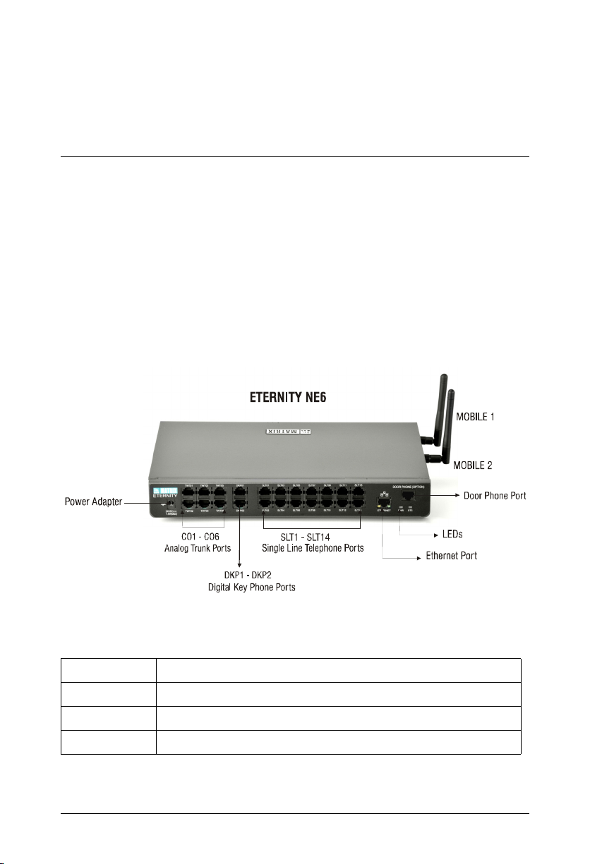
ETERNITY NE6 is used throughout this document.
This Quick Start is meant to help you install and configure the basic parameters of
the system. For advanced configuration and feature description, please refer the
System Manual provided to you on the CD-ROM shipped with your ETERNITY NE.
ETERNITY NE Overview
ETERNITY NE variants:
ETERNITY NE2 2 CO Ports, 2 GSM/UMTS Ports, 4 SIP trunks, 2 DKP, 4 SLT, 8* IP Extensions.
ETERNITY NE3 3 CO Ports, 2 GSM/UMTS Ports, 4 SIP trunks, 2 DKP, 6 SLT, 8* IP Extensions.
ETERNITY NE4 4 CO Ports, 2 GSM/UMTS Ports, 4 SIP trunks, 2 DKP, 10 SLT, 8* IP Extensions.
ETERNITY NE6 6 CO Ports, 2 GSM/UMTS Ports, 4 SIP trunks, 2 DKP, 14 SLT, 8* IP Extensions.
To connect more IP extensions you need to purchase the IP8 license.
*
Matrix ETERNITY NE Quick Start 1
Page 8

Ports and Connectors
Port Description
24VDC- 2A (Max) Connector for the power adapter.
CO Analog trunk port to connect analog trunk line. RJ11
DKP Digital Key Phone port to connect
SLT Single Line Telephone (SLT) port to connect any standard
Ethernet Ethernet port. Can be used as
Door Phone Door Phone port to connect
Mobile 1 &
Mobile 2
connector.
• the proprietary digital key phone of Matrix, EON.
• the PC-based phone EONSOFT.
• the direct station selection console, DSS64 to expand
EON’s key map
analog telephone instrument and fax machine.
• LAN interface to connect a computer/LAN Switch.
• WAN interface* to connect to IP network. As Ethernet
WAN, you can connect a DSL modem/Router or a
LAN Switch.
• a four-wire door phone.
• a door lock release (Relay).
Single SIM mobile ports to connect to the GSM/UMTS
network.
* To connect SIP Trunks/IP extensions the VoIP module (optional) must be present
in your ETERNITY NE. To connect more than 8 SIP extensions, you must purchase
the IP8 license.
LED
LED Description Colour and Cadence
PWR Power LED. Turns on when
power is supplied
STS Status LED. Blinks to indicate
health of the system.
Green. continuous ON
Green. ON 1 second - OFF 1
second, on completion of
boot-up.
2 Matrix ETERNITY NE Quick Start
Page 9

Installing ETERNITY NE
Preparing for Installation
Have the items listed below ready:
• A suitable location to install the ETERNITY NE.
• Necessary telecom wiring in place, with wall jacks for extension lines at the
required locations.
• Standard, good quality, twisted pair telephone cables with 0.5 mm conductor
diameter, with RJ11 plugs.
• A dedicated Power supply outlet close to the system.
• As many standard analog telephone instruments as you want to connect as SLT
extensions. You may select any standard telephone instrument like rotary
phone, Pulse/Tone switchable push-button phone, Feature phone or Cordless
phone.
• A fax machine, if you want to connect one to the SLT port of ETERNITY NE.
• One or two digital keyphones (Matrix proprietary phones), as required, to
connect as DKP extensions.
• One or more active, analog trunk lines from the CO network, as required.
• A SIM card to test mobile network connectivity, if GSM/UMTs module is to be
installed.
• SIP Account information to be configured in the system to test SIP calls, if the
VoIP module is to be installed.
• Any standard Open IP Phone or the Matrix Extended IP Phone to register as
SIP Extension of ETERNITY NE, if required.
• The Pen Drive and the License Voucher if Voice Mail System (VMS) module is
to be installed.
Matrix ETERNITY NE Quick Start 3
Page 10

• A standalone computer or a computer connected in a LAN to access Jeeves,
the web-based configuration tool of ETERNITY NE.
Selecting the Site
Select an appropriate site to install the ETERNITY NE. The site should:
• be well-ventilated, moisture and dust free; not exposed to direct sunlight, heat or
excessive cold, or water; be away from water bodies and sources of water.
• be away from sources of electromagnetic noise such as any radio equipment,
heavy transformers, etc.
• have sufficient network coverage available, if the GS/UMTS module is present in
the system.
This is an electronic device. Protect yourself from shock hazards. Never handle the product in
power on condition. Always wear an electrostatic discharge prevention wrist strap/belt and use a
grounding mat when handling the product.
Protect the ETERNITY NE from heavy voltages entering from CO trunk and Extension lines. Install
Primary Protection Modules (PPM) with Gas Discharge Tubes (GDT) and fuses on entry points for
all trunk lines and extensions.
For Safety Instructions, see the System Manual provided to you on the CD ROM.
Getting Started
• Unpack ETERNITY NE and verify your package contents. In case any of the
items is missing or damaged, contact your Dealer/Distributor.
Package Contents
• ETERNITY NE with side clamps.
• Two self tapping screws (M7x30 PAN PH).
• Screw Grips
• Power Adapter 24VDC, 2Amp
• Ethernet cable
• CD ROM (System Manual, Quick Start, User Card)
• ETERNITY NE User Card
• ETERNITY NE Quick Start
• Warranty Card
4 Matrix ETERNITY NE Quick Start
Page 11

Installing Optional Modules
GSM/UMTS Module
• Unpack the GSM/UMTS Module and verify package contents.
• Make sure power supply is turned off before you begin installation.
• Unscrew and remove the top cover of the enclosure. Keep the screws and the
cover aside.
• Select the Mobile port you want to install the GSM/UMTS module.
• Remove the screws on the studs and keep them aside.
• The slots for the GSM/UMTS module are located on the side panel and are
covered with a flap. Use your finger or any blunt object to press the slot cover
from the outside of the panel to release the flap.
• Now, grasp the flap from inside the enclosure and pull up the flap.
• Gently seat the GSM/UMTS module on the connector on the mainboard such
that the SIM holder and the antenna connector emerge from the respective
slots. The connector pins on the module must make complete contact with those
on the mainboard. Do not apply pressure.
• When the module is seated firmly on the connector on the mainboard, secure
the module with the screws on the studs.
• If you have no other module(s) to install, replace the top cover and secure the
cover with the screws.
VoIP Module
• Unpack the VoIP module and verify package contents.
• Make sure power supply is turned off before you begin installation.
• Unscrew and remove the top cover of the enclosure. Keep the screws and the
cover aside.
Matrix ETERNITY NE Quick Start 5
Page 12

• Locate the connector of the VoIP module on the mainboard. Remove the screws
on the studs for the module and keep them aside.
• Gently seat the VoIP module on the connector on the mainboard. The connector
pins on the module must make complete contact with those on the mainboard.
Do not apply pressure.
• When the module is seated firmly on the connector on the mainboard, secure
the module with the screws on the studs.
• If you have no other module(s) to install, replace the top cover and secure the
cover with the screws.
Voice Mail System Module
• The Voice Mail System (VMS) module is supplied as a Pen Drive, with a License
Voucher which you must activate to use the module. Unpack the Voice Mail
System module and verify package contents.
• Make sure power supply is turned off before you begin installation.
• Unscrew and remove the top cover of the enclosure. Keep the screws and the
cover aside.
• Locate the USB port on the the mainboard. Connect the Pen Drive to the upper
USB port on the mainboard.
• If you have no other module(s) to install, replace the top cover and secure the
cover with the screws.
• Activate the License for the VMS. See “Activating License Key” under
Configuring ETERNITY NE for instructions.
Door Phone Module
• Unpack the Door Phone module and verify package contents.
• Make sure power supply is turned off before you begin installation.
• Unscrew and remove the top cover of the enclosure. Keep the screws and the
cover aside.
6 Matrix ETERNITY NE Quick Start
Page 13

• Locate the connector of the Door Phone module on the mainboard. Remove the
screws on the studs for the module and keep them aside.
• The slot for the Door Phone module is located on the back panel and is covered
with a flap. Use your finger to press the slot cover from the outside of the side
panel of the enclosure, and release the flap.
• Now, grasp the flap from inside the enclosure and pull up the flap.
• Gently seat the Door Phone module on the connector on the mainboard such
that the RJ45 connector of the module is aligned with the slot, and the connector
pins on the module make complete contact with those on the mainboard. Do not
apply pressure.
• When the module is seated firmly on the connector on the mainboard, secure
the module with the screws on the studs.
• If you have no other module(s) to install, replace the top cover and secure the
cover with the screws.
Connecting to Trunks
CO Trunks (Analog two-wire Trunks)
• Use standard, good quality, twisted-wire pair telephone cables with RJ11 plugs
to connect the CO ports of ETERNITY to the Trunk Lines from your CO (central
office).
Mobile Networks
Enabling SIM PIN Protection
• Protect the SIM card from unauthorized use with a Personal Identification
Number (PIN) on the SIM (in consultation with the customer/owner of the SIM).
To enable SIM PIN protection,
• get a mobile handset. Insert the SIM into the mobile handset.
• from the mobile handset, enable PIN Protection.
Matrix ETERNITY NE Quick Start 7
Page 14

• change the SIM PIN to 1234 (this is the default PIN for both SIM cards used
in the system). You can change this SIM PIN later from ETERNITY NE when
configuring the mobile port.
• remove the SIM from the mobile handset.
If you do not want to use PIN protection, insert the SIM in the mobile handset and disable PIN
protection. Remove the SIM Card from the mobile handset and insert it in the mobile port’s SIM
holder tray.
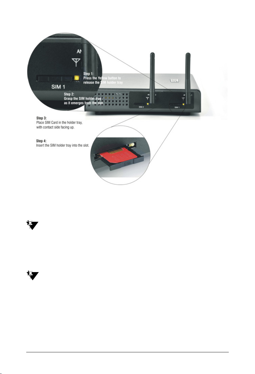
Inserting SIM Card in the Mobile Port
• To insert the SIM card in ETERNITY NE,
• press the SIM holder lock (the small yellow button). You may use a blunt pin
to press the lock button.
• the SIM holder tray emerges from its slot.
• pull out SIM holder tray from its slot.
• now, fit the SIM Card on the tray, with its contact side facing up.
• insert the SIM holder tray back into the slot.
• repeat the same steps to insert the other SIM card.
8 Matrix ETERNITY NE Quick Start
Page 15
• Connect the antenna to the antenna connector.
The UMTS Mobile Ports of ETERNITY NE also provide Wireless WAN Interface. If you want to
use wireless WAN over the Mobile port, you must have UMTS module installed in the system and
Internet services activated on the SIM.
VoIP Network
Before you connect the system to WAN, we recommend that you first connect a computer to the
Network Port of ETERNITY NE, configure the Basic Settings, and then connect to WAN.
• You can connect ETERNITY NE to WAN either over Ethernet port (Ethernet
WAN) or over Mobile Port 1 or Mobile Port 2 (Wireless WAN).
While several installation scenarios are possible, only three most common and
most typical scenarios are depicted here.
Matrix ETERNITY NE Quick Start 9
Page 16

Ethernet WAN
• Use the RJ45 Ethernet cable supplied for the Ethernet port of ETERNITY to
connect the system to the IP network, which may be Public Internet or a LAN.
If connecting to the Public IP Network,
• Plug one end of the RJ45 Ethernet cable into the Ethernet Port of ETERNITY
NE and the other end into the Broadband Router/Modem.
If connecting to a Private Network (Behind a NAT Router),
• Plug one end of the RJ45 Ethernet cable into the Ethernet Port of
ETERNITY NE and the other end into the LAN Switch/Hub.
10 Matrix ETERNITY NE Quick Start
Page 17

Wireless WAN
UMTS
LAN Switch/Hub
Ethernet
LAN
Mobile WAN
• Make sure that
• You have installed a 3G UMTS module.
• a SIM is present in the Mobile port.
• Internet Services are activated on the SIM.
Connecting Extensions
Single Line Telephones (SLT)
• Use standard twisted wire pair the cables of good quality with RJ11 plugs to
connect the analog single line telephone instruments to the SLT ports, SLT1 SLT14 of ETERNITY NE.
• Place the SLTs, fax machine at the desired locations. Connect the SLTs, Fax
machine to the wall jacks.
• Plug the RJ11 end of the telephone cables into the SLT ports of ETERNITY NE.
Terminate the other end of the cables from the SLT ports on the wall jacks to
which the SLTs, fax machine are connected.
Connecting Digital Key Phones (DKP)
• ETERNITY NE supports 2 DKP ports, DKP1 and DKP2. You may connect
EON48, EONSOFT; or you may connect EON48 on one port and DSS64, the
DSS Console, on the other port.
Matrix ETERNITY NE Quick Start 11
Page 18

• Use standard twisted wire pair cables of good quality with RJ11 plugs to connect
the DKP(s).
To connect EON48,
• Place the EON48 at the desired location.
• Connect the handset of EON48 to the phone body using the spring cord
supplied with the phone.
• Connect EON48 to the wall jack. Plug one end of the RJ11 cable into the
connector of
EON48 labeled as ‘Line’. Plug the other end into the wall jack.
• To connect EON48 to ETERNITY, plug the RJ11 end of the telephone cable into
the DKP port of ETERNITY NE and terminate the other end of the telephone
cable from the DKP port on the wall jack.
To connect DSS64 to EON48,
• Place DSS64 next to EON48.
• Connect DSS64 to the wall jack. Plug the RJ11 end of the telephone cable into
the connector on DSS64. Plug the other end into the wall jack.
• To connect DSS64 to ETERNITY, plug the RJ11 end of the telephone cable into
a DKP port of ETERNITY and terminate the other end of the cable from the DKP
port on the wall jack.
To connect EONSOFT,
• Plug the RJ11 end of a telephone cable into the DKP port of ETERNITY NE.
Terminate the other end from the DPK port on the wall jack.
• Plug the RJ11 end of a second cable into the connector labeled as ‘DKP’ on the
dongle of EONSOFT. Plug the other end into the wall jack.
For detailed instructions on installing EONSOFT, refer the System Manual.
12 Matrix ETERNITY NE Quick Start
Page 19

Connecting SIP Extensions
When there is a VoIP module (optional) present in the ETERNITY NE, the
system allows registration of 16 SIP extensions.
You may register any SIP-enabled device like an IP-phone, a Soft phone,
Analog Phone Adapter, as the 'SIP Extension' of the ETERNITY NE.
You may also connect SETU VP248, the Extended IP Phone for ETERNITY as
SIP extension. The Extended IP Phone takes on all the functions of EON48, the
proprietary digital key phone.
The first 8 SIP extensions are free. To increase the number of SIP extensions, you will require the
IP8 License. Make sure you have a valid Key for this license when connecting more than 8 SIP
Extensions.
The SIP Extensions may be registered either over Ethernet WAN or over Wireless
WAN, according to your preference and your IP network installation scenario.
Ethernet WAN
If ETERNITY NE is connected to a Public Network,
• Connect SETU VP248, the Extended IP Phone, or any Open IP Phone to the
LAN Switch.
• Register any SIP client on the public network as SIP Extension.
When you register any SIP device, other than the Extended IP Phone, on the public network as
SIP Extension, you must configure the Registrar Server Address of ETERNITY NE, the Registrar
Server Port, the SIP ID, Authentication ID and Password in the SIP device.
Matrix ETERNITY NE Quick Start 13
Page 20

GSM/UMTS
PSTN
WAN
DSL Modem/
Router
IP
CO
Ethernet
LAN Switch/Hub
If ETERNITY NE is connected to a Private Network (Behind the NAT),
• Connect SETU VP248, the Extended IP Phone, or any standard IP Phone to the
LAN Switch.
• You may also register any SIP device (Extended IP Phone or Open IP phone)
on the public network as SIP Extension. In which case, configure Port
Forwarding for SIP and RTP on the Router.
IP
14 Matrix ETERNITY NE Quick Start
Page 21

Wireless WAN
GSM/UMTS
CO
LAN Switch/Hub
Ethernet
WAN
Router
UMTS
CO
LAN
DSL Modem/
IP
Wireless WAN (Mobile 1)
LAN Switch/Hub
Ethernet
• Connect SETU VP248, the Extended IP Phone, or any standard IP Phone to the
LAN Switch.
• You may also register any SIP device on the public network as SIP Extension.
Matrix ETERNITY NE Quick Start 15
Page 22

Connecting SETU VP248 as Extended SIP Extension
You are recommended to complete the following steps before connecting the
Extended IP Phone to ETERNITY NE:
• Decide the location of the Extended IP Phone: within the same network or
outside, according to your installation scenario.
• Log in to the web-browser Jeeves. Read the topics “How to access Jeeves” and
“Basic Configuration” for instructions.
•Configure DHCP Server on the Network Parameters page under Basic
Settings of Jeeves.
• Assign an extension number to the Extended IP phone on the Extension
Numbering Plan page under Basic Settings of Jeeves.
• For the SIP extension number you assigned to the Extended IP phone,
configure these parameters on the MATRIX Extended IP Phone Settings page
of Jeeves.
• Enable Matrix Extended IP Phone Mode.
• Enter the MAC Address of the Extended IP Phone.
• Assign the Registrar Server IP Address, as per you installation scenario.
• For instructions, see the topic SIP Extensions in the System Manual.
Now, follow the steps described below to install the Extended IP phone. The
instructions are common for all models of the SETU VP248. For the purpose of
illustration, the premium model, SETU VP248P, has been used.
• Unpack the SETU VP248 box and verify package contents.
• Mount the phone on a desk or wall at a location convenient to you.
• Connect the Handset to the Phone body; plug the long straightened end of the
phone cord into the handset jack at the bottom of the phone, and the short end
in to the bottom of the handset.
16 Matrix ETERNITY NE Quick Start
Page 23

• If you want to use a Headset (not supplied) with your phone, you may plug a
headset with a 2.5 mm single connector in to the headset jack on the left side
panel of the phone.
OR
• You may plug a headset with an RJ11 connector in to the headset port at the
bottom of the phone.
• Connect the LAN Port of SETU VP248 to the LAN Switch/Hub.
• To connect your phone to a computer on your desk, use an Ethernet cable (not
supplied with this phone). Connect the PC Port of the phone with LAN Port of
the computer.
• Plug the connector of the Power Adapter in to the power jack
1. The SETU VP248 does not have a power switch.
Matrix ETERNITY NE Quick Start 17
1
.
Page 24

If you want to use Power over Ethernet (PoE), ensure that your LAN supports
Welcome to Matrix
Booting ...
Welcome to Matrix
Loading ...
PoE. Supply power through an 802.3af connection on the LAN Port of the
phone. Do not connect the Adapter!
• Plug the Power Adapter in to a power outlet and switch ON power supply.
• When you power the phone, the boot process will be initiated in the following
sequence.
• All keys with LEDs, including the Speaker key and the Ringer LED, will glow.
• The LCD display will light up. The following message will appear on it, as the
phone boots:
• As soon as the ‘Loading...’ message appears on the phone display, press # key.
18 Matrix ETERNITY NE Quick Start
Page 25

• To select the firmware as Extended IP Phone, move the cursor by pressing the
Select the firmware
Standard S IP
Extended S IP
Select the firmware
Standard S IP
Extended S IP
Welcome to Matrix
Down navigation key V.
• When the cursor is placed under the Extended - IP Phone, press Enter key.
• The phone will start loading the Extended IP Phone Firmware. It will display
current firmware being loaded.
L oading V05R01_ExtSIP
Matrix ETERNITY NE Quick Start 19
Page 26

• After loading the firmware, the phone will prompt you to change Network
Yes
No
DHCP discovery...!
Settings.
C h a n g e N e t w o r k S e t t i n g s ?
• Press Enter key to select ‘No’ or wait for three seconds.
If you want to change the Network Settings, you may select ‘Yes’, by moving the cursor to Yes
with the Up key and pressing the Enter key.
• The phone makes DHCP Discovery and fetches its IP Address and Server IP
Address from the ETERNITY NE.
On getting the IP Address, the phone initiates Auto Configuration to download
the configuration files from ETERNITY NE.
• As the phone downloads the configuration files, the file names will appear one
by one.
20 Matrix ETERNITY NE Quick Start
Page 27

T r y i n g f o r C o n f i g. f i le
L a n g u a ge S t r . x m l
M on 2 0 D EC 16 :5 8 N A
303 R ec ept io n 2
• On successful download of all configuration files, the phone attempts to register
with ETERNITY NE.
A t t e m p t i n g R e g i s t r a t i o n
• On successful registration, the phone will display the current day, date and time,
the extension number and name assigned to the extension phone.
Matrix ETERNITY NE Quick Start 21
Page 28

Setting up the Voice Mail System
Door Phone
Door Phone
To complete the installation of the the Voice Mail System (VMS), all you need to do
is:
• connect a computer to the Ethernet Port of ETERNITY NE using the RJ45 cable
supplied for the port.
• open a Web browser on the computer to access the embedded web-server,
Jeeves.
• activate the License on the Voucher sent to you with the VMS package.
• configure the Network port settings for the VMS from Jeeves.
Connecting Door Phone and Door Lock
The ‘Door Phone’ connector on the ETERNITY NE has the door phone port and the
digital output port (DOP).
You may connect any standard 4-wire Door Phone and a Door Lock release relay to
this port.
Lock Device
DOP
• Make sure the Door Phone and Door Lock conform with the specifications of the
door phone port and the digital output port.
22 Matrix ETERNITY NE Quick Start
Page 29

Technical Specifications of the Door Phone Port
Specification Val ue
Speaker Output 1.41Vrms (max); Single Ended
Mic Input 1.34Vrms (max); Single Ended
Technical Specifications of the Digital Output Port
Specification Val ue
Relay Type Power Relay
Contact Arrangement Normally Open; 1-Form-A
Contact Rating
(Resistive Load)
Operation Time: 8ms (max.)
1.0Amp; 24VDC
• Plug the RJ45 end of the cable supplied for the Door Phone port into the Door
Phone connector of ETERNITY NE. Connect the free end of the cable to the 4wire door phone.
If connecting a Door Lock release, connect the free end of the cable to the Door
Lock release device.
Refer to the pinout details of the Door Phone port to connect the wires correctly.
Pinout Details of Door Phone Connector
Connector Pin Port Connection Color
RJ45
1 Digital Output Port Relay A Orange - White
2 Relay B Orange
3 Door Phone Status Green - White
4 MIC Input Blue
5 Speaker Output Blue - White
6 Analog Ground Green
7 No connection
8 No connection
Matrix ETERNITY NE Quick Start 23
Page 30

Powering on ETERNITY NE
• Connect the power adapter to ETERNITY NE.
• Plug in the power adapter of ETERNITY NE into the power outlet.
• Switch on power supply and wait for the Reset Cycle to complete.
Reset Cycle
• Reset Cycle (Power-ON Self Test) takes about 2 minutes to finish.
• The power LED, PWR, is turned on and remains ON.
• When the system becomes stable after power on, the status LED, STS, blinks
Green (1 second ON, 1 second OFF).
• The LEDs of the DSS keys of the Digital Key Phone(s) attached to the system
are turned on in a sequence. The handshaking between DKP and ETERNITY
lasts for 5-6 seconds.
• At the end of the Reset Cycle, the system loads the default extension numbers,
the date and time. These will appear on the display of the DKP connected to
ETERNITY NE.
• Mobile Ports take about 3 minutes to get registered with the network.
You may now access the web-based programming tool, Jeeves, and configure
ETERNITY NE.
24 Matrix ETERNITY NE Quick Start
Page 31

How to access Jeeves
ETERNITY NE provides an embedded web server with a graphic user Interface
(GUI), Jeeves, for configuration.
To access Jeeves, you will need to connect a computer to ETERNITY NE.
Connecting a Computer
You may connect a standalone computer to ETERNITY NE or grab any computer
connected in the same LAN as ETERNITY NE.
Ethernet Port
LAN Port
Connect a standalone computer to ETERNITY NE, when installing the system for the very first
time. You may connect it to a computer on LAN at a later stage, once you have finished
installation and configuration of the system.
To connect a standalone computer,
• Plug one end of the RJ45 cable supplied into the Ethernet Port of ETERNITY
NE. Plug the other end into the LAN port of the computer.
• Make sure the IP Address of the computer and the Ethernet Port of ETERNITY
do not conflict, and that both are in the same Subnet.
The default IP Address of the Ethernet Port of ETERNITY is: 192.168.1.101
The default Subnet Mask of the Ethernet Port of ETERNITY is: 255.255.255.0
Matrix ETERNITY NE Quick Start 25
Page 32

• Change the Subnet of the computer, if necessary.
• Make sure a web-browser, either Internet Explorer 7 or 8 or Mozilla Firefox, is
installed on the computer.
• Open the browser (Internet Explorer or Mozilla Firefox) on the computer.
• Enter the default IP address 192.168.1.101 of the Ethernet Port of ETERNITY
NE in the address bar of the browser.
• The Welcome page will open.
• In the Login as combo box, select System Engineer.
• In the Password field, enter 1234, the default System Engineer Password.
• Click the Login button.
26 Matrix ETERNITY NE Quick Start
Page 33

On successful login, the home page of the System Engineer configuration mode
opens.
The left pane shows the links Basic Settings, Advanced Settings and
Administration.
Matrix ETERNITY NE Quick Start 27
Page 34

Basic Settings break down the complexities of configuration and are sufficient
to get your system into operation.
Advanced Settings enable you to configure the advanced features and
facilities of ETERNITY NE.
Administration allows you to carry out system maintenance and monitoring like
uploading configuration and firmware, debug, system restart. You can also view
the system details and status of all trunk and extension ports.
• You may now configure the Basic Settings of ETERNITY NE.
28 Matrix ETERNITY NE Quick Start
Page 35

Basic Configuration
There are two ways to do the basic system configuration using Jeeves:
• using the Wizard.
Or
• through Selective Configuration of basic settings.
Using the Wizard
The configuration Wizard leads you step-by-step through the configuration of the
basic settings. To use the Wizard,
• Click the Wizard icon on the top right of your screen.The home page of the
Wizard opens.
• To navigate the Wizard pages use the Next and Back buttons.
• When you press the Next button, the changes on the current page are saved
and the Wizard takes you to the next page.
Matrix ETERNITY NE Quick Start 29
Page 36

• When you press the Back button, you will be prompted to save changes made
on the current page.
•The More button and the Less button on the page allow you to expand
and collapse respectively, the parameters on the page.
•The Expand button expands a link on the page to display all parameters
under the link.
•The Collapse button collapses a link hides all the parameter under a link
on the page.
•The Settings icon allows you to configure the settings of a parameter
further.
• You may exit the Wizard at any time by clicking the Quit button . The
changes you made before you exit will be saved.
Using Selective Configuration
You can choose the parameters you want to configure, and the order in which you
want to configure. To do this,
• Click the Basic Settings link.
• The parameter sub-links appear on the left pane.
30 Matrix ETERNITY NE Quick Start
Page 37

• Click the parameter sub-link you wish to configure.
• The respective parameter page opens.
• Get familiar with the buttons and icons listed below before you begin to change
the settings of the parameters on each page.
More: displays all the parameter links on the page.
Less: displays the essential parameter links on the page.
Expand: expands a link to display all parameters under the link.
Collapse: collapses a link. Hides all parameters under the link.
Settings: allows you to configure the settings of a parameter further.
More link: displays all additional parameters on the page.
Logout: allows you to exit Jeeves.
• Set the desired values on this page and click Submit button to save.
You may use the Wizard or selectively configure the Basic Settings pages,
whichever works best for you. Read the ETERNITY NE System Manual for detailed
instructions.
Activating License Key
To install the Voice Mail System or to connect more than 8 SIP Extensions, you
would need to activate a License Key in the system.
Instructions for Matrix Channel Partners
Your license voucher may be a paper or a PDF (protected) file.
You may activate your License Online. For this, keep the following items ready:
• The License Voucher containing the 16-digit PIN.
• A valid, unique User ID and Password from the Matrix License Support Centre.
• Access to Internet.
Matrix ETERNITY NE Quick Start 31
Page 38

• Current License Key of the system.
Note down the current License Key of the system from the License
Management page of Jeeves.
The features and functions that are currently available on your system appear
under Service Profile.
To activate the License Key online,
• Keep your Current License Key and the License Voucher ready.
• Open a new window on your browser.
• Enter http://115.118.161.162:81/matrixlicense in the address bar of the new
window.
32 Matrix ETERNITY NE Quick Start
Page 39

•The Login to Access page will open.
• Enter your User Name and Password provided by Matrix and click the Login
button.
Matrix ETERNITY NE Quick Start 33
Page 40

On successful login, the License Activation page will open.
34 Matrix ETERNITY NE Quick Start
Page 41

•As Product Family, select the option ETERNITY.
• In the field Current License Key, type the current product license key you noted
from the License Management page of Jeeves.
• Click View button.
• The page will show the current License Profile on ETERNITY. Click the Next
button to continue.
The License Activation page opens.
Matrix ETERNITY NE Quick Start 35
Page 42

• In the License PIN field on this page, enter the License PIN from the Voucher.
36 Matrix ETERNITY NE Quick Start
Page 43

• Click Details. The details appear in the fields Product Family, Product Name,
Product Variant.
• Click the Next button.
Your Current License Profile and your New License Profile will appear on this
page.
• Click the Activate button and wait for a few seconds, as the activation is
initiated.
On successful activation, the confirmation message will appear on your screen
along with the activation date and time.
You will also be sent a confirmation mail to your e-mail ID (registered with
Matrix).
Matrix ETERNITY NE Quick Start 37
Page 44

You may Save, Print, or Email this information for your records, by clicking the
relevant button on the bottom of the page.
• Note down the New License Key generated on this page.
• Go back to the Jeeves window (or log in as System Engineer again, if your
session has ended).
• Open the License Management page under Advanced Settings.
• Enter the new License Key generated in the field Enter License Key.
• Click Submit button.
The Service Profile on this page will be updated according to the license.
38 Matrix ETERNITY NE Quick Start
Page 45

When you activate the Voice Mail System key, it will appear on your Service
Profile.
When you activate your IP8 License to enable 8 IP Users, it will appear on your
Service Profile
• To log off, click Logout.
If you are unable to use Online Activation of the License Key or have no internet access, contact the
Matrix License Support Centre for assistance in generating the new License key.
Matrix ETERNITY NE Quick Start 39
Page 46

Instructions for Customers
To activate your License, you would need the License Voucher containing the 16digit License PIN. Contact your Dealer/Distributor in this regard. Your License
Voucher may be a paper or a protected PDF file.
• Open Jeeves.
• Log in as System Engineer.
• Click the Advanced Settings link.
• Click the License Management link. The License Management page opens.
• Note down the current License Key on this page.
You may view the features and functions that are currently available to you
under Service Profile.
• Send your Current License Key and the License PIN (on the Voucher) to the
Matrix License Support Centre.
• You will receive a new License Key.
• Open Jeeves again.
• Log in as System Engineer.
40 Matrix ETERNITY NE Quick Start
Page 47

• Click the License Management link under Advanced Settings.
• Enter the New License Key you obtained from Matrix in the field Enter License
Key.
• Click the Submit button.
The Service Profile on this page will be updated accordingly.
• To log off, click Logout.
Matrix ETERNITY NE Quick Start 41
Page 48

MATRIX COMSEC PVT. LTD.
Corporate Office:
394-GIDC, Makarpura, Vadodara - 390010, India.
Tel.:+91 265 2630555, Fax: +91 265 2636598
E-mail: Info@MatrixComSec.com
Factory:
39-GIDC, Waghodia - 391760, Dist. Vadodara, India.
Tel.: +91 2668 262056/57
Technical Support:
Tel.: +91 2668 263172/73, Fax: +91 2668 262631
E-mail: Support@MatrixComSec.com
www.MatrixComSec.com
Version 1, February 2011
 Loading...