

Page 1

ETERNITY
Quick Start
Page 2

Page 3
ETERNITY
The IP-PBX with Seamless Mobility
and Universal Connectivity
Quick Start
Page 4

Documentation Disclaimer
Matrix Comsec reserves the right to make changes in the design or components of
the product as engineering and manufacturing may warrant. Specifications are
subject to change without notice.
This is a general documentation for all models of the product. The product may not
support all the features and facilities described in the documentation.
Information in this documentation may change from time to time. Matrix Comsec
reserves the right to revise information in this publication for any reason without
prior notice. Matrix Comsec makes no warranties with respect to this documentation
and disclaims any implied warranties. While every precaution has been taken in the
preparation of this quick start, Matrix Comsec assumes no responsibility for errors
or omissions. Neither is any liability assumed for damages resulting from the use of
the information contained herein.
Neither Matrix Comsec nor its affiliates shall be liable to the purchaser of this
product or third parties for damages, losses, costs or expenses incurred by the
purchaser or third parties as a result of: accident, misuse or abuse of this product or
unauthorized modifications, repairs or alterations to this product or failure to strictly
comply with Matrix Comsec's operating and maintenance instructions.
Copyright
All rights reserved. No part of this quick start may be copied or reproduced in any
form or by any means without the prior written consent of Matrix Comsec.
Version 10
Release date: June 18, 2011
Page 5

Contents
Introduction .................................................................................................... 1
Installing the ETERNITY ................................................................................ 3
Before you Start ................................................................................................ 3
Installing SLT, DKP and TWT Cards ................................................................. 6
Installing the BRI Card ...................................................................................... 7
Installing E&M Card ......................................................................................... 13
Installing Mobile Card ...................................................................................... 15
Installing VoIP Card ......................................................................................... 18
Connecting SIP Extensions ............................................................................. 22
Installing the T1E1PRI Card ............................................................................ 40
Installing VMS Card ......................................................................................... 45
Installing Door Phone Card ............................................................................. 47
Switching ON the system ................................................................................ 49
How to access Jeeves ..................................................................................... 50
Basic Configuration ..................................................................................... 53
‘Region’ ........................................................................................................... 55
Emergency Numbers ....................................................................................... 56
Enterprise Name ............................................................................................. 56
Time Zone-Automatic (Time Table), Day/Night Mode ..................................... 57
Flexible Numbers ............................................................................................ 57
DSS Consoles ................................................................................................. 58
CLIP ................................................................................................................ 60
Class of Service .............................................................................................. 60
Toll Control ...................................................................................................... 61
Trunk Access ................................................................................................... 61
LCR ................................................................................................................. 62
Trunk Landing ................................................................................................. 62
T1E1PRI .......................................................................................................... 64
Mobile Port ...................................................................................................... 66
BRI Port ........................................................................................................... 67
E&M Lines ....................................................................................................... 68
Table of Contents i
Page 6

VoIP Port ......................................................................................................... 69
SIP Trunks ....................................................................................................... 70
SIP Extensions ................................................................................................ 70
Logical Partition ............................................................................................... 72
Door Phone Card ............................................................................................ 73
VMS Card ........................................................................................................ 73
Appendix ....................................................................................................... 85
Universal Slots ................................................................................................ 85
Cable Diagrams for cards of ETERNITY-ME .................................................. 88
Cable Diagram for cards of ETERNITY-GE .................................................. 105
Cable Diagram for cards of ETERNITY-PE ................................................... 111
ii Table of Contents
Page 7

Introduction
Thank you for choosing the Matrix ETERNITY! This Quick Start is meant to help you
setup the ETERNITY and use the basic features.
For detailed description of the installation, advanced configuration and feature
description, please refer the ETERNITY System Manual provided to you on the CDROM.
This Quick Start is applicable for firmware version V10.01 and later.
Matrix ETERNITY Quick Start 1
Page 8

2 Matrix ETERNITY Quick Start
Page 9

Installing the ETERNITY
Before you Start
Before you begin the installation of the ETERNITY ME/GE/PE, make sure that the
required telecom wiring has been done and you have the following items ready:
• A Main Distribution Frame (MDF)
• A suitable location to install the Main Distribution Frame and the ETERNITY
hardware. If you want to install the mobile card, make sure the place you select
has sufficient signal strength.
• Cables for trunk lines and extensions.
Terminate the trunk lines from the service provider network and the extension
lines from the field phones into the Main Distribution Frame.
• The Cards of ETERNITY, as required.
• One or more Single Line Telephone or Digital Key Phones, or IP Phones for
testing.
• Power supply.
The ETERNITY ME, GE and PE work with input voltages ranging between 100240VAC. Arrange for a separate power point and switch, close to the system.
Power supply for the system must be separate from other heavy electrical loads
like Air-conditioners, heaters, welding machines, electrical motors, etc.
• One or more active Two-wire trunk lines for test calls.
• A modem for the ISDN T1E1PRI line.
• An NT1 termination device for the ISDN BRI line.
• Appropriate cables and connectors to set up and test the Ethernet interface of
the ETERNITY and the LAN connection.
Matrix ETERNITY Quick Start 3
Page 10

• A standalone PC or a PC connected in a LAN.
Wall mounting nails
Mounting Template
MDF cable for Switch Card (provided with ETERNITY ME only)
Telephone Personality Guide
ETERNITY Platform
Quick Start and User Card.
Quick Start and
User Card
Support Card
• A SIM card to test mobile network connectivity.
• A SIP Account to test VoIP connectivity.
• Make sure you have separate electrical earth and telecom earth for the safety of the product
and the persons handling it.
• Always wear a properly earthed (grounded) electrostatic discharge preventive belt or wrist
strap while handling the cards of the System.
• Use Primary Protection on trunk and long distance extension lines to protect the system from
lightning and electrical surges.
• Do not install the system near any source of water, corrosive fumes, and electromagnetic
noise such as radio equipment, heavy transformers, faulty electric chokes of tube-lights,
device having a faulty coil, to avoid electromagnetic effect.
Read the System Manual for safety precautions.
• Unpack the system.
• Make sure that your package contains all the below items. If any item is missing
or damaged, please contact the source from where you have purchased the
system.
3 Pin AC Mains cable
RJ-45 Cable
CD containing Voice Messages, System Manual,
Matrix Logos
Warranty Card
4 Matrix ETERNITY Quick Start
Page 11

• Place the system at the location you have selected.
• If installing ETERNITY ME or GE,
• unscrew and remove the filler bracket of the slots you want to insert the
cards.
• insert the cards into the Universal Slots. Make sure the connectors on the
card and those on the motherboard on the backplane make perfect contact.
• press down the levers of the card mounting brackets and secure the card in
its slot with the screws provided.
• If installing ETERNITY PE,
• unscrew the top cover and keep the screws and the cover aside.
• select a Universal Slot to place the card and remove the screws on the
studs.
• seat the card on the slot such that the card connectors make perfect contact
with the connector pins on the CPU.
• secure the card on the slot by fixing the screws on the studs.
• replace and secure the cover after you have completed installation of all
cards and connecting the cables.
See “Appendix” for position of the Universal Slots in your model.
Matrix ETERNITY Quick Start 5
Page 12

Installing SLT, DKP and TWT Cards
• Unpack the SLT, TWT, DKP cards. Remove the filler brackets of the universal
slots and insert the cards.
• Plug the MDF cables provided with each card into the connectors of the cards.
• Terminate the free ends of the MDF cables from the card connectors into the
Krone modules of the Main Distribution Frame. Refer the cable connections
given in the “Appendix” for terminating the cables into the Main Distribution
Frame.
• Connect Single Line Analog Telephone instruments to the SLT ports over the
MDF.
• Connect Digital Key phones, EON42, EON48 and their consoles DSS72 and
DSS16X4 to the DKP Ports over the MDF.
• Connect Two Wire Trunk (Analog Trunk) lines to the TWT ports over the MDF.
6 Matrix ETERNITY Quick Start
Page 13

Installing the BRI Card
• Unpack the BRI card.
• Set the Orientation Type of the BRI Ports as Ter minal (TE) or Network (NT)
mode as per your installation requirement.
In ETERNITY ME
• To set the Orientation Type of the BRI Port as either NT or TE, change the
position of the jumpers located on the main board of the card. Refer the tables
below for jumper positions for each BRI port. Default: All ports are set as TE.
Mode Jumper Position
BRI Port 1 BRI Port 2
J20 J21 J22 J23 J24 J25 J26 J27
NT BC BC BC BC BC BC BC BC
TE AB AB AB AB AB AB AB AB
Mode Jumper Position
BRI Port 3 BRI Port 4
J28 J29 J30 J31 J32 J33 J34 J35
NT BC BC BC BC BC BC BC BC
TE AB AB AB AB AB AB AB AB
Mode Jumper Position
BRI Port 5 BRI Port 6
J36 J37 J38 J39 J40 J41 J42 J43
NT BC BC BC BC BC BC BC BC
TE AB AB AB AB AB AB AB AB
Matrix ETERNITY Quick Start 7
Page 14

Mode Jumper Position
BRI Port 7 BRI Port 8
J44 J45 J46 J47 J48 J49 J50 J51
NT BC BC BC BC BC BC BC BC
TE AB AB AB AB AB AB AB AB
In ETERNITY GE
• To set the BRI Ports of ETERNITY GE as NT or TE, refer the tables below to
change the position of the Jumpers on the main board of the BRI Card. Default:
all ports are set as TE.
Mode Jumper Position
BRI Port 1 BRI Port 2
J1 J2 J3 J4 J6 J7 J8 J9
NT BC BC BC BC BC BC BC BC
TE AB AB AB AB AB AB AB AB
Mode Jumper Position
BRI Port 3 BRI Port 4
J10 J16 J17 J18 J14 J15 J19 J20
NT BC BC BC BC BC BC BC BC
TE AB AB AB AB AB AB AB AB
8 Matrix ETERNITY Quick Start
Page 15

In ETERNITY PE
• To set the BRI Ports of ETERNITY PE as TE or NT, refer the tables below to
change the position of the jumpers on the main board of the BRI Card. Default:
all ports are set as TE.
Mode Jumper Position
BRI Port 1 BRI Port 2
J1 J2 J4 J5 J7 J8 J10 J11
NT BC BC BC BC BC BC BC BC
TE AB AB AB AB AB AB AB AB
Common Instructions for installing the BRI card in ETERNITY ME, GE,
and PE
• A BRI Port can be configured in the TE/NT mode. Depending on the installation
and configuration scenario, Termination Resistance of 100 should be inserted.
• When the BRI Port is configured as Network, NT mode, power may have to be
fed to the terminal equipment connected to the BRI port.
Inserting Termination Resistance on the BRI Port
• Termination Resistance should be inserted in the following cases
1. When the BRI port is configured in NT mode.
2. When the BRI port is configured in TE mode and connected in a Point-to-Point
configuration as shown in figure 1.
Figure 1:
Matrix ETERNITY Quick Start 9
Page 16

3. When the BRI port is configured in TE mode and connected as the last
ISDN
Network
NT
BRI Line
BRI TEBRI TE
Other ISDN
Equipment
Equipment
terminal on the S0 bus (Multi-point configuration) as shown in figure 2.
Figure 2:
BRI TE
Other ISDN
ETERNITY
• Termination need not be inserted in case 2 and 3 above, if the S0 bus itself
supports Termination resistors.
• Termination need not be inserted if the BRI port of ETERNITY (configured in TE
mode) is connected as any terminal other than the last terminal on the S0 bus
(in a Multi-point configuration).
• To set the 100 termination on the BRI port set the Jumpers J3 and J4 located
on the BRI Module (daughter board) of the card as shown in the table.
Function Jumper Position
J3 J4
To insert 100termination (default position) AB AB
To remove 100termination BC BC
Feeding Power to Terminal Equipment
• To feed power from ETERNITY to the terminal equipment connected to a BRI
port in the NT mode, change the position of the Jumpers J1 and J2 on the BRI
modules (daughter board) of the BRI Card as shown in the table.
Function Jumper Position
J1 J2
To feed power on Tx and Rx wires (Phantom Power) AB AB
To feed power on separate pair of wires BC BC
No power to be fed to the terminal equipment (default position) Open Open
10 Matrix ETERNITY Quick Start
Page 17

The number of ISDN Terminals that can be connected on the BRI port configured in the NT mode
depends on the power consumed by the ISDN terminals.
From signaling point of view, up to 8 terminal equipment can be connected on the BRI port
configured in the NT mode. But the maximum power that can be fed to a single BRI port is 50mA.
So, connect ISDN Terminals to the BRI port according to the power consumed by them, which
together do not exceed 50mA.
• Insert the BRI card in any free Universal Slot and secure the card.
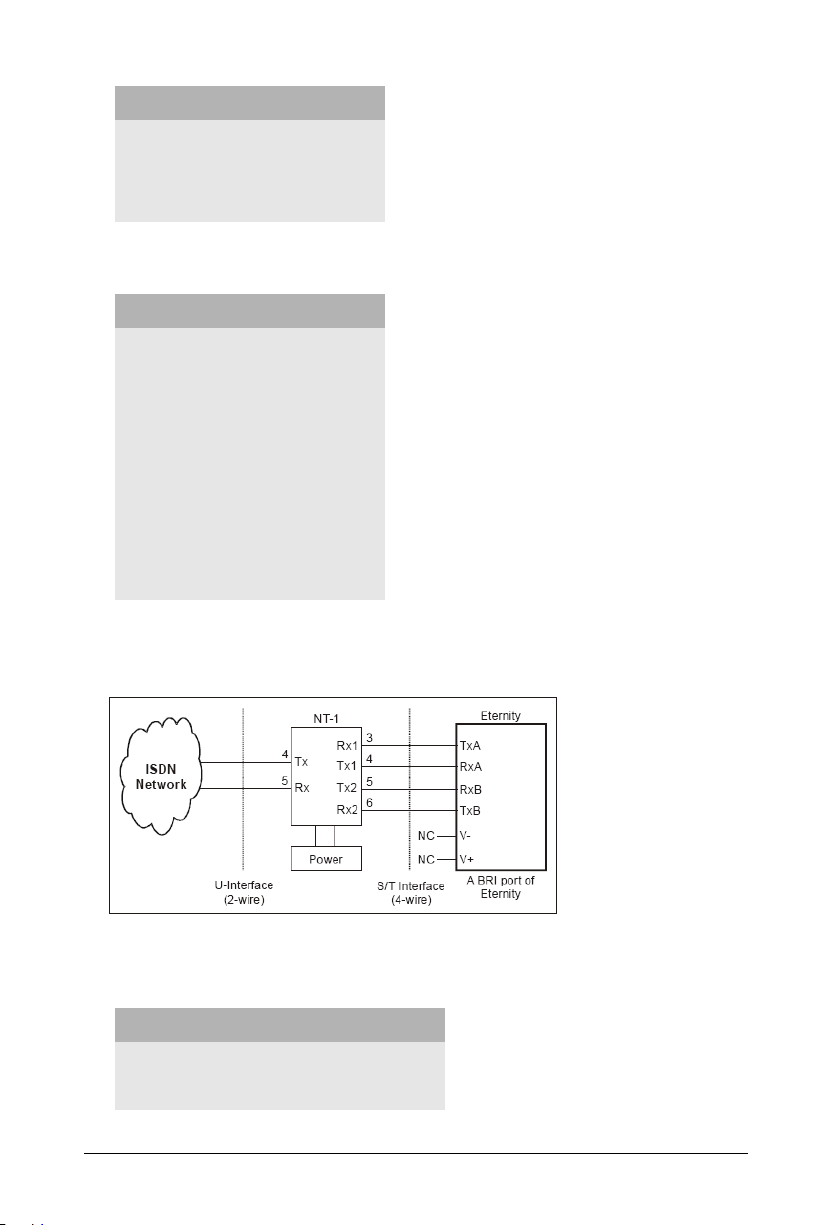
• Use the cable supplied for each connector on the BRI card to connect the BRI
Ports to the NT1 device supplied by your ISDN service provider. See the tables
below for configuration and pinout details.
Configuration of the U interface (RJ-45) at NT1
Pin Number Pin Details
4 Tx
5 Rx
Configuration of the S/T interface (RJ-45) on NT1
Pin Number Pin Details
3 Rx1
4 Tx1
5 Tx2
6 Rx2
Pin details of BRI Port in TE mode
Pin Number Signal Color
1 -- Orange-White
2 -- Orange
3 TX-A Green-White
4 RX_A Blue
5 RX_B Blue-White
Matrix ETERNITY Quick Start 11
Page 18
Pin Number Signal Color
6 TX_B Green
7 VOUT- Brown-White
8 VOUT+ Brown
Pin details of BRI Port in NT Mode
Pin Number Signal Color
1 -- Orange-White
2 -- Orange
3 RX-A Green-White
4 TX_A Blue
5 TX_B Blue-White
6 RX_B Green
7 VOUT- Brown-White
8 VOUT+ Brown
This is a typical connection of a BRI Line to the ETERNITY ME BRI port in the TE
mode:
LED indication for BRI Ports
Port Status LED Color LED Cadence
Port active Red Continuously ON
Port not active Green Continuously ON
12 Matrix ETERNITY Quick Start
Page 19

Installing E&M Card
• Unpack the E&M card.
• The E&M Card supports E&M Interface Type IV and Typ e V connection.
• To select the Interface Type you require, change the position of the jumpers on
the E&M module. See the table below for jumper position to set Interface Type.
Function Jumper Position
J1 J2
Type IV E&M Interface (default position) AB AB
Type V E&M Interface BC BC
• Select the Speech Interface—2-wire speech or 4-wire speech—as required, by
changing the jumper position on the E&M module. See the table below for
jumper positions.
Function Jumper Position
J3 J4
4-wire speech interface AB AB
2-wire speech interface (default position) BC BC
• Select a universal slot for the E&M card and insert the card in the slot and
secure it.
• Connect the cables supplied with the E&M card into the connectors on the E&M
Card.
• Connect the free end of the cable into the E&M Ports of the other PBX/Router/
Tie Line equipment with appropriate crossing of the wires.
• For connecting the wires, refer the pinout details for each E&M Card Type and
for each E&M Type and Speech Interface Type given in the “Appendix”.
Matrix ETERNITY Quick Start 13
Page 20

LED indication for E&M Ports
Stage
Initialization
At Power ON Red
Standby (waiting to
be detected by
Master Card)
Normal (Port Event)
M-Wire High Green LED of the Port continuously ON
M-Wire Low LED of the Port continuously OFF
E-Wire High Red LED of the Port continuously ON
M-Wire Low LED of the Port continuously OFF
E-Wire and M-Wire
High
LED
Color
Green
Green,
Orange
Orange LED of the Port continuously ON
LED Cadence
L1 to L8 glow one after the other in a
sequence, ON 100ms -OFF.
L1 ON 100ms-OFF,
L2 100ms ON-OFF,
L3 100ms ON-OFF,
L4 100ms ON-OFF……L8 100ms ON-OFF
L1 to L8 glow one after the other in a
sequence, ON 100ms -OFF.
L1 ON 100ms-OFF,
L2 100ms ON-OFF,
L3 100ms ON-OFF,
L4 100ms ON-OFF……L8 100ms ON-OFF
L1 toggles Green ON 1 sec, Orange ON 1 sec
Errors
Controller RAM
failure
External RAM failure Orange All LEDs Toggle at 2 sec
Eprom failure Orange All LEDs Toggle at 3 sec
Invalid Slot detected Orange All LEDs Toggle at 6 sec
Orange All LEDs Toggle at 1 sec
14 Matrix ETERNITY Quick Start
Page 21

Installing Mobile Card
• Unpack the Mobile Card.
• Connect the antenna (provided with the Mobile card) to the connector on the
Mobile card.
• You may enable PIN Protection on your SIM card before inserting it into the
Mobile port.
• If you want to use PIN Protection,
• First, insert the SIM card in a Mobile handset.
• From the Mobile handset change the PIN to 1234.
• Remove the SIM from the Mobile handset and insert in the Mobile Port of the
ETERNITY.
• Installing the SIM with PIN value 1234, allows you to change the SIM PIN
from the ETERNITY later.
• If you don't want to use PIN Protection,
• Insert the SIM in the Mobile handset and disable PIN Protection.
• Remove the SIM Card from the Mobile handset.
• Insert the SIM Card (PIN changed to 1234), with its contact side facing down
into the SIM Holder on the Mobile card.
Failure to follow the instructions on PIN protection may cause your SIM Card to be blocked and you
will require Personal Unblocking Number (PUK) to reactivate it again.
• To insert the SIM cards into the SIM holders, refer the illustrations of the Mobile
cards.
Matrix ETERNITY Quick Start 15
Page 22

ETERNITY ME GSM/3G 8 Card
Antenna 1
Antenna 2
M
o
bi
l
e
2
M
o
b
i
l
e
1
M
o
b
i
l
e
4
M
o
b
i
l
e
3
M
ob
i
l
e
6
M
ob
i
l
e
5
M
o
b
i
l
e
8
M
ob
i
l
e
7
M
o
d
u
l
e
1
M
o
d
u
l
e
2
M
o
d
u
l
e
3
Insert SIM
Card Contact
facing down
S
p
l
i
t
t
e
r
Antenna
M
o
b
i
l
e
M
o
b
i
l
e
1
M
o
b
i
l
e
4
M
o
b
i
l
e
3
M
o
d
u
l
e
1
M
o
d
u
l
e
2
Insert SIM
Card Contact
Facing down
ETERNITY GE GSM/3G 4 Card
4
e
l
u
d
o
M
2
16 Matrix ETERNITY Quick Start
Page 23

ETERNITY PE GSM/3G 4 Card
• Now, insert the Mobile card in any of the free Universal slots and secure it.
LED indication for Mobile Ports
Event LED Color
Port Disable -- LED Off
Port Idle -- LED Off
Port Active (All states other
than Ring and Speech)
Ring Event Green 400ms ON-200 ms OFF-
Speech Green Continuous ON
Module Initialization Orange 200ms On-200ms Off-
PUK required Orange 200ms On-200ms Off-
SIM PIN faulty Orange 200ms On-200ms Off-
SIM Absent Orange 200ms On-200ms Off-
Network Link Down
(absence of Network)
1
Cadence in msec
(1 cadence is of 3000msec)
Red Continuous ON
400ms ON-200 ms OFF
200ms On-200ms Off200ms On-200ms Off200msOn-200ms Off200ms On-1200ms Off (5 Blinks)
200ms On-200ms Off200ms On-200ms Off200msOn-1600ms Off
200ms On-200ms Off200ms On-2000ms Off (3 Blinks)
200ms On- 2400ms Off (2 Blinks)
Orange 200 ms On-2800 ms Off (1 Blink)
1. There is no LED on the Mobile Cards of ETERNITY GE and ETERNITY PE.
Matrix ETERNITY Quick Start 17
Page 24
Installing VoIP Card
IP
Mast er Ethernet Port
WAN
LAN
M
a
s
t
e
r
C
a
r
d
S
w
i
t
c
h
C
a
r
d
V
o
I
P
S
e
r
v
e
r
C
a
r
d
ETERNITY ME16S
• The ETERNITY VoIP Card has a WAN Port and a LAN Port. The default IP
Address of the WAN Port is: 192.168.001.116. The default IP Address of the
LAN Port is: 192.168.002.031
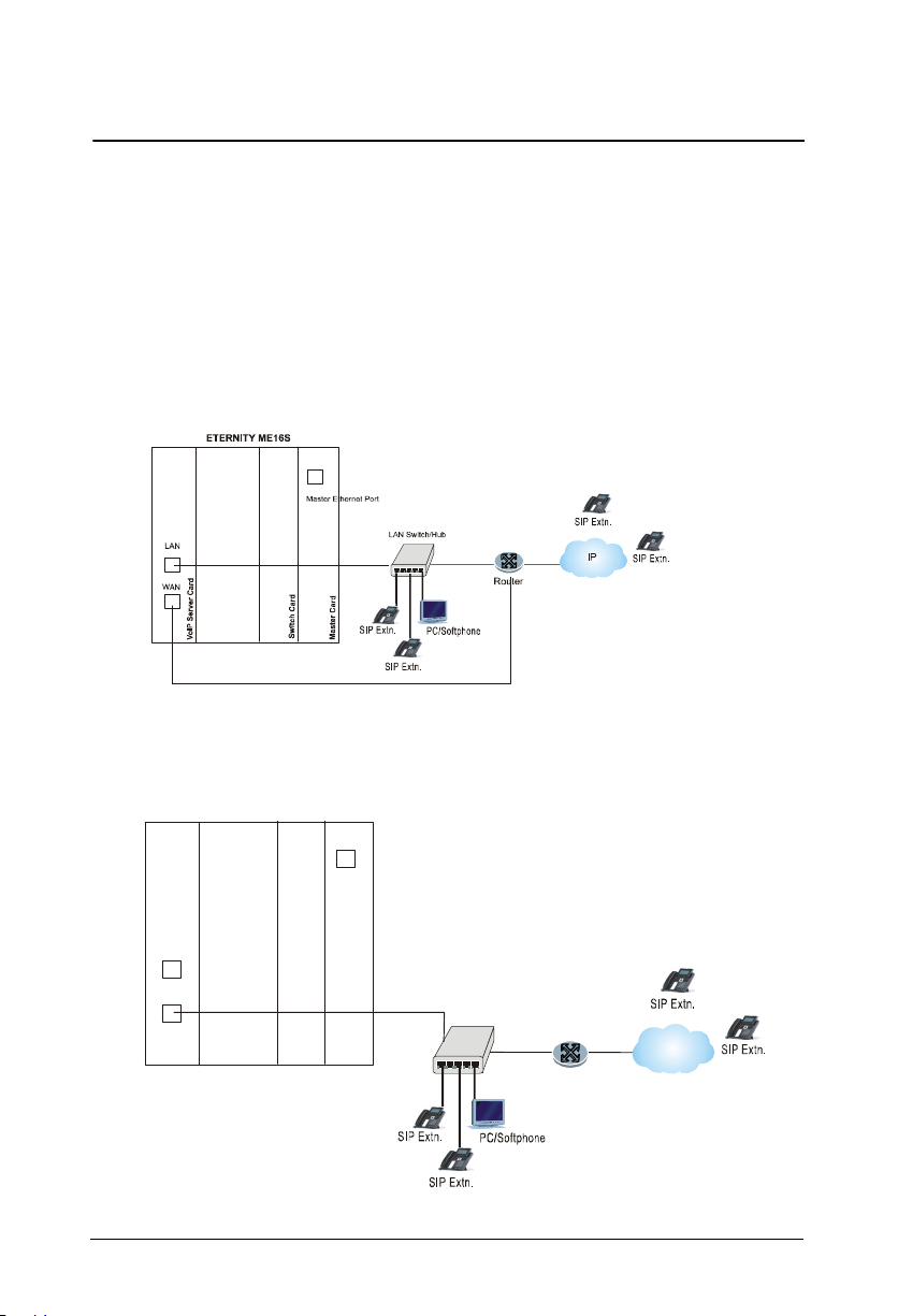
• The VoIP Card can be installed in typically two application scenarios: in a Public
IP Network or in a Private network (behind a NAT Router). It can also be
connected to both networks.
VoIP Card installed in Public Network
VoIP Card installed in a Private Network
18 Matrix ETERNITY Quick Start
LAN Switch/H ub
IP
Router
Page 25
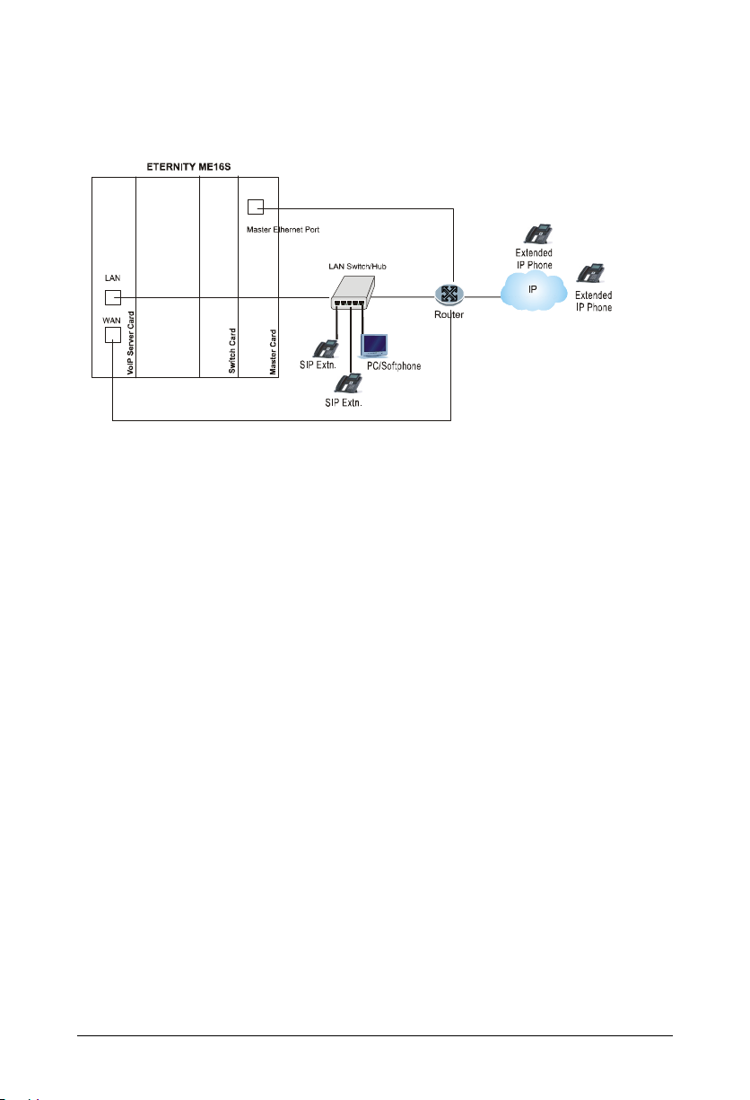
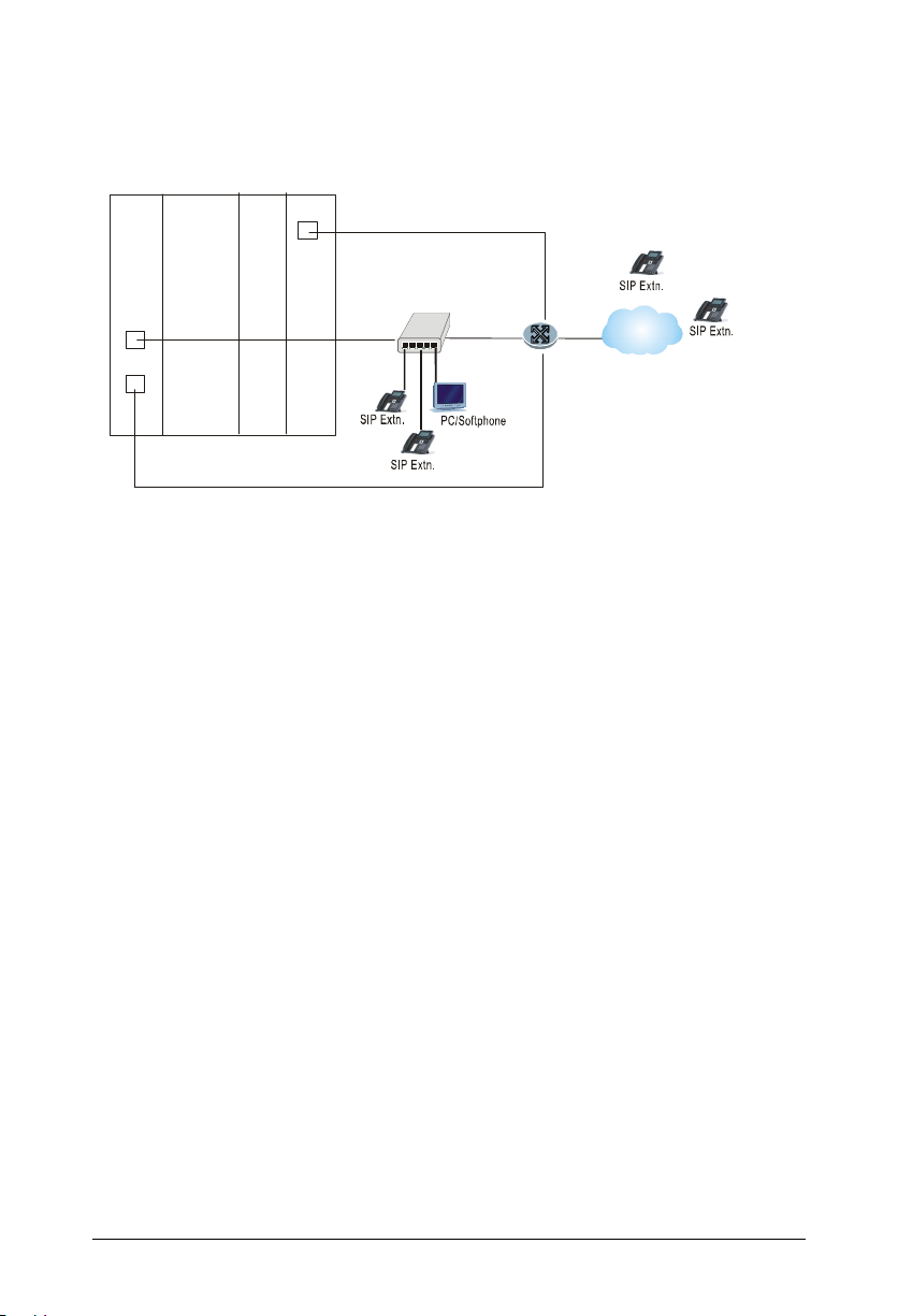
VoIP Card connected to the Public and Private Network for Matrix
Extended IP phones
• Unpack VoIP Card.
• Insert VoIP Card in any free universal slot and secure it in its slot, and secure
the card in its slot.
If connecting to the Public Internet Network,
• Plug one end of the Ethernet cable supplied with the VoIP card into the WAN
Port of the VoIP Card and the other end into the Router/Modem.
If connecting to a Private Network,
• Plug one end of the Ethernet cable supplied with the card into the WAN Port of
the card and the other end into the LAN Switch/Hub.
If connecting to the Public Network for registering Extended IP Phones,
• Plug one end of the Ethernet cable supplied with the VoIP card into the WAN
Port of the VoIP Card and the other end of the cable into the Router/Modem.
• Connect the LAN Port of the VoIP Card to the LAN Switch/Hub.
• Connect the Master Ethernet Port of the ETERNITY to the Router/Modem.
If you have completed installation of the system, switch on power supply and
observe the LED indication during Reset Cycle.
Matrix ETERNITY Quick Start 19
Page 26

• The ETERNITY ME and GE VoIP Cards have two LEDs:
• LED 1 indicates the status of the VoIP card.
• LED 2 indicates the status of any of the SIP Trunks to which this LED is
assigned.
• There are no LEDs the VoIP card of ETERNITY PE.
• Described below are the LED indication of LED 1 and LED 2 of the VoIP card of
ETERNITY ME and GE.
LED 1 - VoIP Card Status Indication
VoI P C ar d sta tus LED Color Cadence
Booting Up (Power On) Green Continuous On
Once Stack Construct
COMMAND is received from
Master, LED will remain ON Red
and wait for the WAN and DSP
download response.
WAN Stack Construction Failed (PPPoE connection is not
established or IP Address Invalid
or DHCP Client does not retrieve
network parameters or any other
reason)
LAN Stack constructed or not
DSP Image is downloaded
successfully or not
WAN Stack constructed
successfully
LAN Stack constructed or not
DSP Image is not downloaded
successfully (in all DSPs)
WAN Stack constructed
successfully
LAN Stack constructed
successfully
DSP Image not downloaded
successfully (in any DSP but not
all)
Red Continuous On
Red
Red
Green
On 1 sec-Off 1 sec
On 1 sec-Off 1 sec
On 500msec-Off 3500 msec
On 500msec-Off 3500 msec
20 Matrix ETERNITY Quick Start
Page 27

VoI P C ar d sta tus LED Color Cadence
WAN Stack constructed
successfully
LAN Stack construct Failed
DSP Image not downloaded
successfully (in any DSP but not
all)
WAN Stack constructed
successfully
LAN Stack construct Failed
DSP Image is downloaded
successfully (in all DSPs)
WAN Stack constructed
successfully
LAN Stack constructed
successfully
DSP Image is downloaded
successfully (in all DSPs)
Card goes live
.LED 2 - SIP Trunk Status Indication
SIP Trunk Status LED Color Cadence
Green On 500msec-Off 500msec On
Green
Green On 1 sec - Off 1 sec, On 1sec - Off 1 sec
500msec-Off 2500msec
On 500msec-Off 500msec On
500msec-Off 500msec On 500msec-Off
1500 msec
SIP Trunk - Disabled Red Continuous On
Registration Failed Authentication Password Invalid
Registration Failed Configuration Parameter Invalid
Registration in Progress Green On 500msec-Off 3500 msec
Registration Successful Green Continuous On
SIP Trunk Status will be indicated by LED2 only after you have programmed the Registration LED
in the SIP Trunk Parameters.
Red On 500msec-Off 3500msec
Red On 500msec-Off 500msec
On 500msec-Off 2500 msec
Matrix ETERNITY Quick Start 21
Page 28

Connecting SIP Extensions
The SIP Extensions function like DKP/SLT extensions of the ETERNITY. You can
register any SIP-enabled device, like an IP-phone, a Soft phone, Analog Phone
Adapter, as the SIP Extension of the ETERNITY.
The Number of SIP Extensions supported by ETERNITY varies by model:
• ETERNITY ME: 999 SIP Extensions.
• ETERNITY GE: 500 SIP Extensions.
• ETERNITY PE: 50 SIP Extensions.
For SIP extensions, you will require the IP8 License. Make sure you have a valid License Key when
connecting SIP Extensions. For more information on Licensing, see the topic ‘License
Management’ in the System Manual.
You may connect the Standard and Extended IP Phones of Matrix.
The Matrix Extended IP Phone, SETU VP248, takes on all the functions of EON48,
the proprietary digital key phone of Matrix, except the following features:
• Background Music
• CO Call Waiting
• Hot Desking
• Live Call Screening
The SIP Extensions may be registered over WAN or over LAN according to your
preference and your IP network installation scenario.
You can register the same SIP Extension from three different locations.
If you register the Extended IP Phone outside the Region/Country selected for ETERNITY, the
time and Time Zone dependant features, such as Alarms, Reminders, Time Zone Display, of the
phone at each location will operate according to the Real Time Clock of ETERNITY. Also, Access
Codes and Emergency Numbers will work according to the Region/Country selected for
ETERNITY.
22 Matrix ETERNITY Quick Start
Page 29
If the ETERNITY Master Card/CPU Card and VoIP Card are connected to a
Router
IP
LAN Switch/Hub
Master Ethern et Port
WAN
LAN
M
a
s
t
e
r
C
a
r
d
S
w
i
t
c
h
C
a
r
d
V
o
I
P
S
e
r
v
e
r
C
a
r
d
Public Network,
ETERNITY ME 16S
IP
• Connect SETU VP248, the Extended IP Phone, or any Open SIP device to the
LAN Switch.
• Register any SIP device (Extended IP phone or Open SIP phone) on the public
network as SIP extension.
When you register the Matrix Extended IP Phone with ETERNITY, make sure
the Master Ethernet Port of ETERNITY and the WAN port of the VoIP Card
are connected to the public network. The Master Ethernet Port is used for Auto
Configuration of the Matrix Extended IP Phones.
When you register a SIP device other than the Matrix Extended IP Phone on the
public network as SIP Extension of ETERNITY, in this SIP device, you must
configure the following:
• the Registrar Server Address of ETERNITY ME
• the Registrar Server Port
• the SIP ID
• Authentication ID and Password.
Matrix ETERNITY Quick Start 23
Page 30

If the ETERNITY Master/CPU Card and VoIP Card are connected to a Private
IP
Master Ethernet Port
WAN
LAN
M
a
s
t
e
r
C
a
r
d
S
w
i
t
c
h
C
a
r
d
V
o
I
P
S
e
r
v
e
r
C
a
r
d
ETERNITY ME16S
Network (Behind the NAT),
LAN Switch/H ub
IP
Router
• Connect SETU VP248, the Extended IP Phone, or any standard IP Phone to the
LAN Switch.
• You may also register any SIP device (Extended IP Phone or open SIP phone)
on the public network as SIP Extension.
• When you register the Matrix Extended IP Phone with ETERNITY, configure
Port Forwarding for Master Ethernet Port of ETERNITY and the WAN port of
the VoIP Card on the Router.
• The Master Ethernet Port is used for Auto Configuration of the Extended IP
Phones.
Connecting SETU VP248 as Extended SIP Extension
You are recommended to complete the following steps before connecting the Matrix
Extended IP Phone to ETERNITY:
• Decide the location of the Extended IP Phone, whether within the same network
or outside, according to your installation scenario.
24 Matrix ETERNITY Quick Start
Page 31

• If you want to use the DHCP Server on your LAN for assigning IP Address to
the Extended IP Phone, do the following:
• use DHCP option 224 and Data Type as ‘String’ to provide Server Address
to the Extended IP Phones.
• Program the IP Address or the Dynamic DNS Domain Name of the Master
Ethernet Port of ETERNITY in the DHCP option.
• Log in to Jeeves. For instructions, read the topic “How to access Jeeves”.
• Assign an extension number (SIP ID or Access Code) to the Extended IP
Phone. For instructions on assigning SIP ID, see the topic Configuring SIP
Extensions, in the System Manual.
• For the SIP extension number you assigned to the Extended IP Phone, go to the
Location settings of the extension, and do the following:
• Enable Matrix Extended IP Phone Mode.
• Enter the MAC Address of the Extended IP Phone.
• Assign the Registrar Server IP Address, as per you installation scenario.
For instructions, see the topic Matrix Extended IP Phone Settings under
Configuring SIP Extensions in the System Manual.
Now, follow the steps described below to install the Extended IP Phone. The
instructions are common for all models of the SETU VP248. For the purpose of
illustration, the premium model, SETU VP248P, has been used.
• Unpack the SETU VP248 box and verify package contents.
• Mount the phone on a desk or wall at a location convenient to you.
• When mounting the phone on the wall, detach the Foot Stand from the
bottom of the phone.
Matrix ETERNITY Quick Start 25
Page 32

Pull out the Foot Stand.
Foot Stand.
Press down
to attach/detach
Foot Stand.
Keyhole Slot 1
Keyhole Slot 2
Press down
to attach/detach
• Fix two screws of appropriate diameter on the wall, ensuring that they are
aligned with the Keyhole Slots 1 and 2.
• Use wall plugs, if required, to fix the screws. Leave the screw heads
protruding from the wall to fit into the Keyholes.
• Now, mount the phone on the wall, with the screws fitting into the Keyhole
slots.
• When you mount the phone on a desk, you can attach the Foot Stand in two
ways as illustrated in the following.
Foot Stand attached at 20
o
Angle
26 Matrix ETERNITY Quick Start
Page 33

Foot Stand attached at 45o Angle
If you attach the Foot Stand at 45°, the phone will be placed in an almost
upright position on your desk.
• Decide which of these positions would work for you best and accordingly
attach the Foot Stand.
• Connect the Handset to the Phone body.
• Plug the long straightened end of the phone cord into the handset jack at the
bottom of the phone marked with the handset symbol.
• Plug the other (short straight) end of the phone cord into the jack at the
bottom of the handset.
Matrix ETERNITY Quick Start 27
Page 34

• If you want to use a Headset (not supplied) with your phone, you may plug a
headset with a 2.5 mm single connector into the headset jack on the left side
panel of the phone.
OR
You may plug a headset with an RJ11 connector in to the headset port at the
bottom of the phone.
• Connect the LAN Port of SETU VP248 to the LAN Switch/Hub or a Router/
Modem, according to your installation scenario.
• To connect your phone to a computer on your desk, use an Ethernet cable (not
supplied with this phone) to connect the PC Port of the phone to the LAN Port of
the computer.
• Plug the connector of the Power Adapter in to the power jack at the back of the
phone. Use only the adapter provided with the phone to prevent any damages
that may arise from the use of other adapters.
If your phone supports Power over Ethernet (PoE), and you want to use PoE,
make sure that your LAN supports PoE. Supply power through an 802.3af
connection on the LAN Port of the phone. Do not connect the Adapter!
28 Matrix ETERNITY Quick Start
Page 35

• Plug the Power Adapter into a power outlet.
Welcome to Matrix
Booting ...
Welcome to Matrix
Loading ...
Select the firmware
Standard S IP
Extended S IP
• Switch ON power supply.
• When you power the phone, the boot process will be initiated in the following
sequence.
• All keys with LED, including the Speaker key, and the Ringer LED, will glow.
• The LCD display will light up and the following message will appear on it, as
the phone boots:
• As soon as the ‘Loading...’ message appears on the phone display, press #
key.
• Select the firmware Extended - IP Phone. Move the cursor by pressing the
DOWN navigation key V.
Matrix ETERNITY Quick Start 29
Page 36

• When the cursor is placed under the Extended IP Phone, press Enter key.
Select the firmware
Standard S IP
Extended S IP
Welcome to Matrix
L oading V05R01 Ext SIP
Yes
No
• The phone will start loading the Extended IP Phone Firmware. It will display
current firmware being loaded.
• After loading the firmware, the phone will prompt you to change
Network settings.
C h a n g e N e t w o r k S e t t i n g s ?
• Wait for a few seconds.
If you want to change the Network Settings, press the Enter key. Detailed instructions for changing
the Network Settings of the phone are provided at the end of this topic. See “Network Settings”at
the end of this topic.
30 Matrix ETERNITY Quick Start
Page 37

• The phone makes DHCP Discovery and fetches its IP Address and Server
DHCP discovery...!
L a n g u a g e S t r . x m l
Address from the DHCP Server.
• On getting the IP Address and Server Address, the phone initiates Auto
Configuration to download the configuration files from ETERNITY ME.
• As the phone downloads the configuration files, the file names will appear
one by one.
T r y i n g f o r C o n f i g . f i le
• On successful download of all configuration files, the phone attempts to
register with ETERNITY.
A t t e m p t i n g R e g i s t r a t i o n
Matrix ETERNITY Quick Start 31
Page 38

• On successful registration, the phone will display the current day, date and
2001 Reception
time, the extension number and name assigned to the Extended IP Phone.
Mon 10 MAY 15:40
Network Settings
You can change the network settings of the Extended IP Phone by accessing the
Local Menu of the phone. To move the cursor and scroll through the menu and
submenu options, use the following touch sense navigation keys on your phone.
• The Enter key to make a selection or to complete an action.
• The Up key to move up the Menu.
• The Down key move down the Menu.
• The Forward key move the cursor one character.
• The Back key to move the cursor one character and to return from the
submenu to the main menu.
The cursor is a non-blinking underscore that appears under the first letter of the first
option in the menu.
To make a selection in the menu, you must move the cursor in the desired direction
using the Up, Down, Forward and Back key.
When the cursor is at the desired position, press Enter key to make a selection.
32 Matrix ETERNITY Quick Start
Page 39

Accessing Network Settings
Yes
No
j
tuv
Voice Mail
Canc el
Forward DND Names
Mute Conference Transfer
HoldReleaseRedial
j
tuv
Canc el
Forward DND Names
Mute Conference Transfer
HoldReleaseRedial
Local Menu
Mon 10 MAY 15:40
2001 Reception
You can access the Network Settings of the Extended IP Phone in any of the
following stages:
1. During start-up, when the phone prompts you to change the network settings
after loading the firmware.
C h a n g e N e t w o r k S e t t i n g s ?
You must press the Enter Key to select Yes and access network settings.
2. When the phone is making Network discovery, downloading configuration files,
attempting registration.
You must press the Enter Key to access network settings,
3. When the phone is in idle state. You must press the DSS key assigned to ‘Local
Menu’.
Call Back
Call Back
CA04
CA04
CA03
CA03
CA02
CA02
CA01
CA01
12
12
abc
abc
45
45
ghi
ghi
kl mno
kl mno
7
7
pqrs
pqrs
8
8
0
0
*
*
3
3
def
def
6
6
9
9
wxyz
wxyz
#
#
Matrix ETERNITY Quick Start 33
Page 40

When you press the Local Menu DSS Key (in idle state) or when you press the
L O C A L M E N U
N
Network Status
MAC :00:1 b:09 :00:9a :a7
Connection Type
IP Address
Subnet Mask
Gateway Address
Enter key during any process, the Local Menu appears on your phone display.
etwork Parameters
You can configure Network Parameters and view Network status from the Local
Menu.
Configuring Network Parameters
• In the Local Menu of the phone, select Network Parameters by pressing the
Enter Key.
• The Network Parameters submenu appears.
NET WORK PARAMETERS
• Use the Down/Up key to reach the desired network parameter and press Enter
key to select and change the settings.
• You can configure all network parameters described below, except the MAC
Address.
Connection Type
• Select the Connection Type as DHCP, PPPoE or Static according to the IP
Addressing scheme of your network.
If you select DHCP or PPPoE, the phone will be assigned IP Address, Subnet
Mask and Gateway Address, DNS Address Server Address, automatically by
the DHCP/PPPoE server.
34 Matrix ETERNITY Quick Start
Page 41

For PPPoE Connection Type, you must configure the PPPoE User ID and
Password provided by the Internet Service Provider.
If you select Static, you must assign the IP Address, Subnet Mask and Gateway
Address to the phone.
IP Address
• If you select Static as Connection Type, enter the static IP Address to be
assigned to the phone.
Enter the desired Static IP Address by pressing the digit keys.
To enter the dot/period in the IP Address, press the digit key ‘1’ twice.
Subnet Mask
• If you select Static as Connection Type, enter the Subnet Mask to be applied on
the phone by pressing the digit keys.
To enter the dot/period in the IP Address, press the digit key ‘1’ twice.
Gateway Address
• If you select Static as Connection Type, enter the Gateway Address here. This
is the IP Address of the LAN Port of the Router.
DNS Server
• If you select Static as Connection Type, select the DNS Server option Static
and configure the DNS Address.
• If you select DHCP or PPPoE as Connection Type and your Internet Service
Provider provides DNS Address, select the DNS Server option Automatic.
However, if your Internet Service Provider does not provide DNS Address,
select Static and configure the DNS Address.
DNS Address
• If you select DNS Server as Static, enter the DNS Address here.
To enter dot/period in the IP Address, press the digit key ‘1’ twice.
Matrix ETERNITY Quick Start 35
Page 42

DNS Domain Name
• If you select DNS Server as Static, enter the DNS Domain Name here. DNS
Domain Name is optional.
PPPoE User ID
• If you have selected PPPoE as Connection Type, you must enter the User ID
provided to you by your Internet Service Provider.
PPPoE Password
• This is the password provided by your Internet Service Provider for the PPPoE
User ID. If you have selected PPPoE as Connection Type, you must enter the
password provided by your Internet Service provider here.
PPPoE Service Name
• If your Internet Service Provider has provided a Service Name, enter the Service
Name here. If your Internet Service Provider has not provided a Service Name,
do not configure this parameter.
Server Address
• ETERNITY Master/CPU Card works as the Auto Configuration Server for the
phone. Enter the IP Address or the Dynamic DNS Domain Name of the Master
Ethernet Port of ETERNITY here. Default: blank.
The phone sends the request for configuration files to this Server Address.
If you have selected DHCP as Connection Type, the phone will get the Server
Address automatically from the DHCP Server. For this, use DHCP option 224
and Data Type as ‘String’ to provide Server Address from the DHCP Server.
For PPPoE and Static Connection Types, you need to enter the Server Address.
Server Port
• Enter the Web Server Port of the Master Ethernet Port of ETERNITY here.
The phone sends the request for configuration files to this port.
Valid range of the port is: 80 or 1024–65535. Default: 80.
36 Matrix ETERNITY Quick Start
Page 43

VLAN Setting
If your phone is connected to a virtual LAN, you need to configure VLAN Settings.
To enable the VLAN switch to correctly route packets generated by the phone
and the computers (on the LAN) to each other, the packets must be tagged with
a VLAN header.
The VLAN header consists of the VLAN ID (12-bit) and Class of Service (CoS,
3-bit) for prioritization of traffic
2
.
The meaning of CoS bits with respect to traffic type is as follows:
CoS Traffic Type
0Best Effort
1 Background
2Spare
3 Excellent Effort
4 Controlled Load
5Video
6Voice
7 Network Control
• Select Phone VLAN/COS to add VLAN header to the packets generated by the
phone, and add VLAN header to the packets relayed from the PC to its LAN port
(packets generated by the PC connected to its PC port).
• To configure Phone VLAN/COS, select Enable?. The VLAN ID will be
tagged on all packets generated by the phone (SIP, RTP, DNS, ARP, etc.).
Default: Disabled.
•Select VLAN ID and enter the VLAN ID that you have assigned to the VLAN
in which the IP Phones are connected. Valid range: 0-4094. Default: 1.
2. The IEEE 802.1P standard allows Layer2 switches to prioritize the traffic, thus providing
Quality of Service (QoS), i.e. better handling of data that pass over a network, thereby
resulting in greater reliability and quality. Quality of Service (QoS) on Layer2 is referred to
as Class of Service (CoS) which is defined by IEEE 802.1P.
Matrix ETERNITY Quick Start 37
Page 44

•Select SIP CoS and define the CoS (priority) bits in all SIP packets. Valid
M AC : 0 0: 1 b: 09 :0 0 :9 a: a 7
IP : 19 2. 1 68 .2 0 1. 2 05
MASK : 25 5.255.255 .0
G W : 1 92 . 16 8. 2 01 .3
D NS :
range: 0-7. Default: 3
•Select RTP CoS and define the CoS (priority) bits in all RTP packets. Valid
range: 0-7. Default: 6.
•Select PC/VLAN CoS to add VLAN header to all packets entering the PC
Port and leaving the LAN port of the phone. Default: Disabled.
• To configure PC VLAN/COS, select Enable?.
•Select VLAN ID and enter the same ID as you have assigned to the
VLAN in which the computers are connected. Valid range: 0-4094.
Default: 1.
•Select CoS and define the Layer 2 CoS (priority) bits. Valid range: 0-7.
Default: 0.
PCAP
To capture packets sent and received from and by the phone for monitoring
and troubleshooting, you can enable PCAP on the phone. The phone captures
up to 2 MB of packets. For more information and for instructions on how to use
PCAP Trace on the phone, see the topic ‘Using PCAP Trace for the Matrix
Extended IP Phone’, under PCAP Trace in the System Manual.
When you change the Network Settings, the phone will restart.
Viewing Network Status
• In the Local Menu of the phone, place the cursor on Network Status and press
the Enter key.
• The Network Status submenu appears.
NET WORK STATUS
38 Matrix ETERNITY Quick Start
Page 45

Use the Down/Up key to view the status of the various network parameters. The
status of the following parameters appear on your display as you scroll.
• MAC: This is the MAC Address of the phone.
• IP: The current IP Address assigned to the phone.
• MASK: The current Subnet mask assigned to the phone.
• GW: The current Gateway IP Address assigned to the phone.
• DNS: The Domain Name Server address assigned to the phone.
• S. ADD: The IP Address or Dynamic DNS Domain Name of the Master
Ethernet Port of ETERNITY.
• S. PORT: The Web Server Port of the Master Ethernet Port of ETERNITY.
• DOMAIN: The Domain Name assigned to the phone.
• FIRM: The version of the current Firmware of the phone.
Matrix ETERNITY Quick Start 39
Page 46

Installing the T1E1PRI Card
• Unpack T1E1PRI Card.
• By default, termination resistance of T1E1 port set as 120 for E1 connectivity.
• To use the T1E1 port for T1 connectivity, termination resistance should be
changed to 100.
In ETERNITY ME
• T1E1Port -1 termination resistance can be changed using DIP switch SW5.
• Set Pins of SW5 as shown below to set termination resistance.
Pin-1 Pin-2 Pin-3 Pin-4 Resistance
OFF OFF ON OFF 120 (for E1)
OFF ON OFF OFF 100 (for T1)
• T1E1 Port 2 termination resistance can be changed using DIP Switch SW2.
• Set Pins of SW2 as shown below to set termination resistance.
Pin-1 Pin-2 Pin-3 Pin-4 Resistance
OFF OFF ON OFF 120 (for E1)
OFF ON OFF OFF 100 (for T1)
In ETERNITY GE
• Termination resistance can be changed, using Jumper J5.
• To set the Line Termination Resistor for the PRI Port for T1 or E1 Connectivity,
you must change the position of the jumper J5. Refer the table below.
Jumper Position Meaning
J5 BC To set termination resistance of 120 for E1 connectivity
J5 AB To set termination resistance of 100 for T1 connectivity
40 Matrix ETERNITY Quick Start
Page 47

• By default J5 is set to BC position to provide 120 termination resistance for E1
connectivity.
• To set 100 termination resistance for T1 connectivity, set jumper J5 to AB
position.
In ETERNITY PE
Termination Resistance of the PRI Port for T1 or E1 Connectivity is set by changing
the position of the Jumper J2 as given in the table below:
Jumper Position Meaning
J2 BC To set termination resistance of 120 for E1 connectivity
J2 AB To set termination resistance of 100 for T1 connectivity
By default the jumper J2 is in BC position to provide 120 for E1 connectivity.
To s e t 1 0 0 termination resistance for T1 connectivity, set jumper J2 to AB position.
• Connect one end of the RJ45 cable provided with the T1E1PRI Card of
ETERNITY ME/GE/PE to the T1E1 Port and the other end to the modem
provided by the ISDN Service Provider.
LED indication of T1E1PRI Card of ETERNITY-ME and ETERNITY-GE are
shown below. There are no LEDs on T1E1PRI Card of ETERNITY PE.
LED indication on ETERNITY-ME T1E1PRI Card
• The ETERNITY ME T1E1PRI Card has four LEDs: L1, L2, L3 and L4.
• LED L1 and L2 are assigned to T1E1 Port 1, while LED L3 and L4 are assigned
to Port 2.
• LED L1 shows Card Heart Bit as well as status of the Port1.
LED indication on ETERNITY-GE T1E1PRI Card
• The ETERNITY-GE T1E1PRI Card has 2 LEDs: LED1 and LED2.
• LED patterns are defined as shown below for different state and signaling as
shown below.
Matrix ETERNITY Quick Start 41
Page 48

1. Port Active Mode
Signaling Type: E1-PRI
LED1/LED3 Pattern:
Port Status Color Cadence
Layer 1 established successfully GREEN Continuous ON
CRC4 Alarm GREEN 100ms ON-100 ms OFF
BFA Alarm RED 500ms ON-500 ms OFF
LOS Alarm RED Continuous ON
LED2/LED4 Pattern:
Port Status Color Cadence
Layer 1 established successfully GREEN Continuous ON
RAI Alarm RE D 500ms ON-500 ms OFF
AIS or LOS Alarm RED Continuous ON
Signaling Type: E1-CAS
LED1/LED3 Pattern:
Port Status Color Cadence
Layer 1 established successfully GREEN Continuous ON
CRC4 Alarm GREEN 100ms ON-100 ms OFF
MFA Alarm RED 100ms ON-100 ms OFF
BFA Alarm RED 500ms ON-500 ms OFF
LOS Alarm RED Continuous ON
LED2/LED4 Pattern:
Port Status Color Cadence
Layer 1 established successfully GREEN Continuous ON
Y-Bit Alarm GREEN 100ms ON-100 ms OFF
42 Matrix ETERNITY Quick Start
Page 49

Port Status Color Cadence
AIS16 Alarm RE D 100ms ON-100 ms OFF
RAI Alarm RED 500ms ON-500 ms OFF
AIS or LOS Alarm RED Continuous ON
Signaling Type: T1-RBS or T1-PRI
LED1/LED3 Pattern:
Port Status Color Cadence
No Alarm GREEN Continuous ON
TFA Alarm or MFA Alarm RED 500ms ON-500 ms OFF
AIS Alarm RED 100ms ON-100 ms OFF
LOS Alarm RED Continuous ON
LED2/LED4 Pattern:
Port Status Color Cadence
Layer 1 established successfully GREEN Continuous ON
RAI or LOS Alarm RED Continuous ON
2. Port Maintenance Mode
LED1/LED3 Pattern:
Port Status Color Cadence
Maintenance Mode RED - GREEN 500 ms RED-500 ms GREEN
LED2/LED4 Pattern:
Port Status Color Cadence
Near end loop back wait before activate RED 100ms ON-100 ms OFF
Near end loop active RED Continuous ON
Near end loop back wait before deactivate RED 500ms ON-500 ms OFF
Far end loop back wait after activate GREEN 100ms ON-100 ms OFF
Matrix ETERNITY Quick Start 43
Page 50

Port Status Color Cadence
Far end loop active GREEN Continuous ON
Far end loop back wait after deactivate GREEN 500ms ON-500 ms OFF
3. Port Disable Mode
LED1/LED3 Pattern:
Port Status Color Cadence
Port Disable RED Continuous ON
LED2/LED4 Pattern:
Port Status Color Cadence
Port Disable OFF OFF
44 Matrix ETERNITY Quick Start
Page 51

Installing VMS Card
• Unpack VMS Card.
• Insert VMS Card into a universal slot and secure the card.
• Switch on power supply and observe the reset cycle and the LED indication of
the VMS Card.
At Power ON,
• All LEDS are OFF.
• L1 LED glows green as soon as initialization process starts. Initialization
process starts after approximately 100 seconds.
• After approximately 80 seconds of glowing of L1, LEDs will follow the sequence
as under:
• Glow Green-500ms-Glow Red-500ms-Glow Orange 500 ms-LEDs turned
OFF.
In Normal Condition, LED1 will indicate the following:
LED indication of VMS Card
Condition LED Color Cadence
Normal Green 1 sec On - 1 sec Off
File System Error Re d 1sec On - 1 sec Off
Pen Drive Error-Pen Drive
Full
3
Re d Five times 100ms On-100ms Off
(for 1 sec) - 1 sec Off
• For configuration instructions, under Basic Configuration, see “Configuring the
VMS Card”.
• If you need to generate configuration and debug reports, connect the COM Port
of the VMS Card with that of a PC using the communication cable supplied with
the card.
3. There is no LED on the VMS Card of ETERNITY PE.
Matrix ETERNITY Quick Start 45
Page 52

• If you want to use FTP to upgrade Software of the VMS Card, upload recorded
voice messages, store Back-up of Configuration files and Mailbox messages,
connect the Ethernet port of the VMS card to a standalone PC or a PC on LAN.
• Plug in one end of the Ethernet cable supplied with the card into
the Ethernet Port of the VMS Card.
Plug the other end of the cable into the Ethernet port of a standalone
•
PC or into a LAN Switch.
When you connect the VMS Card to a to a LAN PC, you need to make sure that
• The IP Address of the Ethernet Port of the VMS Card and the Ethernet Port of the LAN PC are
not the same.
• The Ethernet Port of the VMS Card and the Ethernet Port of the PC are in the same Subnet.
46 Matrix ETERNITY Quick Start
Page 53

Installing Door Phone Card
• The Door Phone Card is a special card for the ETERNITY PE models only. The
card provides the interface to run electronic gadgets and operate Door Phones
with the ETERNITY PE.
• Unpack the card and seat the card on any of the Universal Slots. Secure the
card on the studs labeled H1, H2 and H3 with the three screws provided.
• The Door Phone Card has 3 Door phone Ports, 3 Digital Output Ports, and a
single Digital Input Port.
• For each connector on the card, a separate RJ45 cable is provided. Refer the
pinout details of the ports of the Door Phone Card provided in the Appendix to
connect the wires to the MDF.
• Connect any standard 4-wire door phones to the Door Phone ports.
• You can connect any automated control application gadget to the Digital Output
Port and a sensor device to the Digital Input Port.
• If using a Door Phone, you can connect a door lock release device to the Digital
Output Port to be used in conjunction with the Door Phone.
Do not connect any device that does not conform with the Technical Specifications of the ports!
Matrix ETERNITY Quick Start 47
Page 54

A typical Installation of the Door Phone Card is illustrated below.
48 Matrix ETERNITY Quick Start
Page 55

Switching ON the system
• Switching ON the system
• Switch ON the system, it takes 2 to 3 minutes for initiation.
Reset Cycle on ETERNITY ME and GE
• On completion of the initialization, LED L1 on Master Card/CPU Card will blink
Green with cadence of 1Sec ON - 1 Sec OFF, continuously.
Reset Cycle on ETERNITY PE
• When the system becomes stable after Power-ON, LED L1 glows Orange and
remains steady ON. L2 blinks Green – 1 sec. ON and 1 sec OFF.
Matrix ETERNITY Quick Start 49
Page 56

How to access Jeeves
ETERNITY provides a Graphic User Interface (GUI), Jeeves, the proprietary webbased programming software of Matrix. It is an HTTP server built into the
ETERNITY.
Jeeves can be accessed by connecting the Master Ethernet Port of ETERNITY with
the Ethernet Port of a standalone computer or a LAN Switch/Hub. Make sure a webbrowser, either Internet Explorer 6 with SP2 (Service Pack) or Mozilla Firefox, is
installed on the computer on which Jeeves is to be accessed.
Now, follow these steps:
• Connect the Master Ethernet Port of the ETERNITY to the Ethernet Port of a
standalone computer or a LAN Switch/Hub using the RJ-45 cable provided with
the system.
• Make sure the IP Address of the standalone PC does not conflict with the IP
Address of the Master Ethernet Port of ETERNITY, and that the computer and
ETERNITY are in the same Subnet. You may have to change the IP Address
and Subnet of ETERNITY as well as that of the computer.
• When you connect ETERNITY to a LAN Switch, the IP Address of the Master
Ethernet Port must not conflict with the IP Address assigned to any device on
the LAN. Also, the Master Ethernet Port of ETERNITY must be in the same
Subnet as the computer on the LAN, from where it is to be accessed.
• You must change ETERNITY’s IP Address and Subnet Mask, if the LAN uses
‘Static” IP Address. If the network has DHCP or PPPoE IP addressing,
ETERNITY will be assigned IP Address and Subnet Mask automatically by the
DHCP/PPPoE server. You do not need to change IP Address or Subnet Mask.
• The default IP Address of ETERNITY’s Master Ethernet Port is 192.168.1.101
and Subnet Mask is 255.255.255.0
• Follow the steps given below to change the IP Address and Subnet Mask of
ETERNITY.
1. Dial 1#91-1234 (1234 is default SE Password) to enter in SE Mode (from
any SLT/DKP).
2. To change the IP Address, dial the command 2110-<IP Address>
50 Matrix ETERNITY Quick Start
Page 57

For example, issue command 2110-192168050010, to change the IP Address
as (192.168.50.10).
3. To change the Subnet Mask, dial the command 2111-<Subnet Mask>
4. Dial 00 to exit from SE Mode.
Matrix ETERNITY Quick Start 51
Page 58

52 Matrix ETERNITY Quick Start
Page 59

Basic Configuration
• Open the Web browser (Internet Explorer/Mozilla Firefox) on the (Standalone or
LAN PC) to which the ETERNITY is connected.
• Enter the current IP address of Master Ethernet Port of ETERNITY on the
address bar of the browser.
This may be the default IP Address or the IP Address you reassigned to
ETERNITY’s Master Ethernet Port (refer “How to access Jeeves”).
• Click Login as System Engineer.
Matrix ETERNITY Quick Start 53
Page 60

• The Login page of the System Engineer mode on Jeeves will open.
• Now, enter the valid SE password. The default SE password is 1234.
• On successful login, the following programming options appear on your screen.
54 Matrix ETERNITY Quick Start
Page 61

• Enter the desired programming option, by clicking the respective link. For
instance, if you want to use the Quick Installation Wizard-Standard PBX, click
the link. The Wizard will open, you may navigate further.
• To configure ETERNITY, click Use Full Programming Access.
• The left pane shows the links to the features and facilities of ETERNITY. You
may click the desired link to open the respective page.
• To save the changes you make on each page, clicking the Submit button at the
bottom of each page.
Now program the following basic parameters.
‘Region’
Select the ‘Region’ (country) in which the ETERNITY is installed to load the countryspecific Default Settings. By default India is selected as the Region. So, if you are
installing ETERNITY in a country other than India, change ‘Region’. To do this,
• Click the Regional Settings link.
• Click the Region Selection link to open the page.
• In the Region list, select the country the system is installed.
Matrix ETERNITY Quick Start 55
Page 62

• Click Submit to save changes.
• Now, to load the country-specific default settings, click the Default the System
link.
• You will get an alert that default values will be assigned and ask you if you want
to continue.
• Click OK.
• On the prompt: “Enter reverse SE password”, enter the password and click OK.
• The system will load the country-specific default settings.
• Wait for the system to restart.
• Log onto Jeeves again, and continue your configuration tasks.
Emergency Numbers
• Click the Emergency Number link.
• The first five entries of Emergency Number table are non-editable. The system
loads the default Emergency Numbers for a country as per the ‘Region’ you
selected in the first five fields of this table. You can only assign the Outgoing
Trunk Bundle Group to route these numbers.
• If you do not find the Emergency Numbers of your region on this table, program
the numbers at any index on this table from 6 to 10 and assign an Outgoing
Trunk Bundle Group to route the numbers.
• Make sure that trunk lines programmed in the Outgoing Trunk Bundle Group
assigned for Emergency Number, are capable of routing the emergency
numbers.
Enterprise Name
• Click the System Parameters link.
• Enter the name of the Enterprise/Organization using ETERNITY. The name may
be up to a maximum of 80 characters. You may also add the contact address
line, if desired.
• Click Submit to save changes to this page.
56 Matrix ETERNITY Quick Start
Page 63

Time Zone-Automatic (Time Table), Day/Night Mode
• Click the Time Tables link.
• By default all the stations and trunks are assigned Time Table1. The default
settings of Time Table1 are given below:
• Working Hours: 09:00 to 18:00
• Break Hours: 13:00 to 14:00
• Non-working Hours: 18:00 to 09:00
• You may make changes to Time Table1 or choose another Time Table to
customize.
• Click Submit to save changes.
• Now, assign the Time Table you prepared in the ‘Station Basic Feature
Template’ of the stations.
• Assign the Time Table you prepared in the ‘Trunk Feature Template’ of the
trunks.
• You can also set the Time Zone for the system manually using the Day/Night
Mode feature. To know more, see the System Manual.
Flexible Numbers
By default, the different station types of ETERNITY are assigned Flexible Numbers
as given below:
• SLT: 2001 to 2512
• DKP: 3001 to 3128
• ISDN Terminal: 3201 to 3264
• SIP Extension: 3301 to 3800
You can change the flexible numbers of these station types according to your
preference, on their respective configuration pages:
• Go to ‘SLT Parameters’ page under ‘SLT Configuration’ to change the flexible
numbers of SLTs.
Matrix ETERNITY Quick Start 57
Page 64

• Go to ‘DKP Parameters’ page under ‘DKP Configuration’ to change the flexible
numbers of DKPs.
• Go to ‘ISDN Parameters’ page to change the flexible numbers of ISDN
Terminals.
• Go to ‘SIP Extensions’ page under ‘VoIP Configuration’ to change the flexible
numbers of SIP extensions.
• Click ‘Submit’ to save your changes on each page.
DSS Consoles
Each Digital Key Phone can be assigned maximum 2 DSS Consoles. To assign
DSS Console to a DKP, go to ‘DKP Parameters’.
• On the DKP Parameters page, click the ‘Advance’ button, scroll with the
horizontal bar to reach the DSS Parameters.
• Assign the Hardware Slot - Port, to which DSS is connected, to the desired DKP
port as “DSS 1 H/w Slot - Port”.
• To attach second DSS console to same DKP Port, assign hardware slot - port of
other DSS console to the DKP port in “DSS 2 H/w Slot -Port” parameter.
Example:
• The DKP Card is installed in Slot 05.
• Digital Key Phones are connected on the 1st and 2nd port of the DKP Card.
• One DSS is connected to 3rd port of DKP Card.
• Second DSS is connected on 4th port of the DKP Card.
58 Matrix ETERNITY Quick Start
Page 65

• To assign the first DSS to the first DKP, assign Slot5, Port 03 as one in “DKP
DSS 1 H/w Slot - Port” of the software port of DKP 1. Similarly, to the second
DSS to the first DKP, assign Slot5 and Port4 as “DKP DSS 2 H/w Slot - Port”.
Matrix ETERNITY Quick Start 59
Page 66

CLIP
CLI detection on TWT Trunks
• By default, all TWT ports are configured to detect ‘DTMF CLI’.
• First find out the CLI type supported by your CO and configure this parameter
accordingly as Rx CLI Type in the ‘TWT Hardware Template’.
CLI presentation on SLT
• By default, ‘DTMF’ is selected as the CLIP Type on all SLT ports in the default
SLT Hardware Template-01 assigned to them.
• The CLIP Type in the template will be set automatically according to the country/
region specific requirements, when you select the ‘Region’.
• First, find out the CLIP protocol supported by the telephone instrument to
connected on SLT Port and configure this parameter accordingly. To change
CLIP type, go to ‘SLT Hardware Template’.
• You may assign different SLT Hardware Templates to different SLT Ports if
required. Go to ‘SLT Parameters’ to assign SLT Hardware Template to SLT
ports.
No configuration is required for CLI detection on Mobile, T1E1, BRI and SIP Trunks.
No configuration is required for presenting the CLI on DKP and ISDN Terminals, SIP Extensions.
Class of Service
• Class of Service is part of the Station Basic Feature Template. By default all the
stations are assigned Station Basic Feature Template-01, in which COS group
01 is assigned for working hours, break hours and non-working hours.
• Go to ‘Class of Service’ page to check the default settings of the CoS group 01
and customize CoS1 group as required.
• To change the CoS group assigned to the station; go to ‘Station Basic Feature
Template’.
60 Matrix ETERNITY Quick Start
Page 67

• Stations can be provided different COS groups by assigning them different
Station Basic Feature Templates.
• Go to ‘SLT Parameters’ to change Station Basic Feature Template assigned to
SLT Ports.
• Go to ‘DKP Parameters’ to change Station Basic Feature Template assigned to
DKP Ports.
• Go to ‘ISDN Terminal Parameters’ to change Station Basic Feature Templates
assigned to ISDN Terminals.
Toll Control
• Toll Control is part of the Station Basic Feature Template. By default all stations
are assigned Station Basic Feature Template-01.
• By default, all the stations are assigned Toll Control Level - 0 (default Call
Privilege: International Calls) for working hours, break hours and non-working
hours. All stations can make calls as per the allowed and denied number
strings programmed in ‘International Numbers’.
• Go to ‘Regional Settings’, check and change the default settings of ‘International
Numbers’, if required.
• You may also assign Call Privilege as No Calls, Local Calls, Regional Calls,
National Calls and Limited Calls as Toll Control Level 0 to 3. Program the
allowed and denied number strings as per the call privilege type you have
selected for the Toll Control Level, under ‘International Numbers’, ‘Local
Numbers’, ‘Regional Numbers’ and ‘National Numbers’.
• If you have selected ‘Limited Calls’ as the Call Privilege, go to ‘Number List’,
program the Allowed and Denied Number strings in the respective list and
assign the list numbers in the Station Basic Feature Template. By default all the
stations are assigned Station Basic Feature Template - 01.
Trunk Access
• Trunk Access is part of Station Basic Feature Template; by default all stations
are assigned Station Basic Feature Template-01.
• By default all stations are assigned Outgoing Trunk Bundle Group (OGTBG)-01.
Matrix ETERNITY Quick Start 61
Page 68

• By default members of the OGTBG-01 are TWT, BRI, SIP, T1E1, and Mobile
trunks.
• Go to ‘OG Trunk Bundle’ to form the OG Trunk Bundles as desired.
• Go to ‘OG Trunk Bundle Group’, program the OG Trunk Bundles as members of
the OG Trunk Bundle Group.
• Go to ‘Station Basic Feature Template’ assigned to the station, to assign
different OG Trunk Bundle Groups for different Trunk Access Codes.
LCR
• By default, LCR is disabled on all the OG Trunk Bundle Groups.
• To enable LCR Type, go to ‘OG Trunk Bundle Group’ - LCR Type.
• Click the links of Least Cost Routing to program attributes of the LCR.
Trunk Landing
• Routing the incoming call to Trunk Landing Group
• By default all the trunks are assigned trunk landing group (Routing Group)
01.
• By default members of the default Routing Group 01, are DKP 001, SLT 001
and SLT 002.
• Go to ‘Routing Groups’ to program the routing groups with desired
members.
• To assign the Routing Group you programmed to the trunks, go to ‘Trunk
Feature Template’ and assign the routing group to trunks for working hours,
break hours and non working hours.
DID (Direct Inward Dialing)
• By default DID is disabled on all the trunks for working hours, break hours and
non-working hours.
• To enable DID, go to ‘Trunk Feature Template’ and enable the DID for working
hours, break hours and non-working hours as desired.
62 Matrix ETERNITY Quick Start
Page 69

• You can also assign Voice Modules with different DID Greeting messages.
Refer the topic Voice Message Applications in the System Manual to know
more.
CLI Based Routing
• You can land particular calling party numbers on particular destinations, by
programming the desired destination in the CLI-Based Routing Table. By
default this table has no entries (blank).
• Go to ‘CLI Based Routing’ to program the desired destination - Destination Type
and Port Number - for particular calling number.
DDI (Direct Dialing In)
• For DDI, you must assign IC Reference ID and OG Reference ID to T1E1 Port
for working hours, break hours and non-working hours. To do this go to ‘DDI
Routing’.
• Click the links of the ‘DDI Routing’, viz. ‘IC Reference Table’, ‘DDI Routing
Table’ and ‘Outgoing Reference Table’ to program DDI Routing.
• To know more about DDI Routing, refer the System Manual.
Trunk Auto Answer
• By default Trunk Auto Answer is disabled on all the trunks for working hours,
break hours and non-working hours.
• To enable Trunk Auto Answer for working, non-working and break hours, go to
‘Trunk Feature Template’ of the trunks on which this feature is to be enabled.
• You may also assign voice modules for Trunk Auto Answer Greeting messages,
Auto Answer RBT message, and Auto Answer Bye message. Refer the topic
Voice Message Applications in the System Manual to know more.
DISA
• By default Direct Inward System Access (DISA) is disabled on all the trunks for
working hours, break hours and non-working hours.
• To enable DISA for working, non-working and break hours, go to ‘Trunk Feature
Template’ of the trunks on which this feature is to be enabled.
Matrix ETERNITY Quick Start 63
Page 70

To know more about feature interactions of DID, DISA, Trunk Auto Answer, DDI and CLI Based
Routing, refer the topic “Incoming Call Management” in the System Manual.
Operator Group
• By default, all the stations and trunks are assigned Operator-1.
• By default, Routing Group number 32 is programmed as Operator-1 for working
hours, break hours and non-working hours.
• By default, members of the Routing Group 32 are DKP001, SLT 001 and SLT
002.
• Make a list of Operator stations for working hours, break hours and non-working
hours.
• Go to ‘Routing Groups’ to create routing groups with member stations which are
to be used as Operator for working hours, break hours and non-working hours.
• To assign the Routing Group you created as Operators, open ‘Operators’ page.
• To assign Operator to the stations, go to ‘Station Basic Feature Template’.
• Operator for the trunks is to be assigned in the ‘Trunk Feature Template’ of the
trunks.
T1E1PRI
• By default, the orientation type of the T1E1 port is Terminal.
• To connect the T1E1 port with the Public network, the orientation type of the
T1E1 port should be Terminal (TE).
• To connect the T1E1 port for private networking, the orientation type should be
set to Terminal/Network depending on the network scenario.
• Go to ‘Port Parameters’ under the link ‘T1E1 Configuration’ to configure the
basic attributes of the T1E1 port.
• By default, the T1E1 port is set to support “E1 PRI” signaling. Go to ‘Port
Parameters’ - ‘Signal Type’ to change the signaling as T1 PRI/E1 CAS/T1 RBS
as supported by the exchange (Network).
64 Matrix ETERNITY Quick Start
Page 71

E1 PRI Signaling
• Find out the PRI switch variant supported by the exchange.
• In case of private networking set the ISDN switch variant supported by both the
PBXs.
• By default, the PRI Switch variant is ‘ETSI NET5’.
• Go to ‘PRI/Q-Signaling’, to change the attributes of the PRI signaling.
E1 CAS Signaling
• To set E1 CAS signaling on T1E1 port, go to ‘Port Parameters’ - ‘Signal Type’,
configure it as ‘E1 CAS’.
• By default the E1 Line Signaling Variant is ‘ITU T Q.400 – Q.490’ and E1
Registered Signaling variant is ‘MFC R2’.
• If your ETERNITY is connected to the public network, find out the Line Signaling
and Registered Signaling variant supported by the exchange. If you have
installed the ETERNITY in a private network, use the signaling variant
supported by both PBXs.
• Go to ‘E1 CAS Signaling’ to change the attributes of the E1 CAS signaling.
T1 RBS Signaling
• To set T1 RBS signaling on T1E1 port, go to ‘Port Parameters’ - ‘Signal Type’,
configure it as ‘T1 RBS’.
• By default, the T1 Line Signaling Variant is ‘E&M Wink Start FGD’ and
Registered Signaling variant is ‘DTMF’.
• Ask your exchange about the T1 Line Signaling and Registered Signaling
variant supported by the exchange, while in case of private networking set the
signaling variant supported by both the PBXs.
• Go to ‘T1 RBS Signaling’, to change the attributes of the T1 RBS signaling.
• EachT1E1 Port is assigned following templates in default configuration:
• Trunk Feature Template Number 01
• Station Basic Feature Template Number 01
• Station Advance Feature Template Number 01
Matrix ETERNITY Quick Start 65
Page 72

• The assigned templates can be changed or customized as required.
When T1E1 port orientation type is Terminal, the Trunk Feature Template assigned to it is of
relevance.
When T1E1 port orientation type is Network, the Station Basic Feature Template and Station
Advanced Feature Template assigned to it are of relevance.
Mobile Port
• The SIM Card subscribed from the GSM/UMTS Service Provider is to be
installed in the Mobile Port.
• Make sure that you are installing the ETERNITY where sufficient network
coverage is available.
Band Selection
• Select the Frequency Band which is used by your Service Provider. In the
default configuration, the Mobile Port is set to operate at 900+1800 MHz. To
change the Band for the Mobile port, click the link ‘Mobile Configuration’.
• Open ‘Mobile Port Parameters’ and configure the ‘Band Selection’ as required.
Network Selection
• Go to ‘Network Selection’ under ‘Mobile Configuration’ to configure the Network
related attributes.
• By default, all Mobile ports are configured to select the network automatically.
The Network Selection Mode is Automatic.
• If the network is to be selected manually, set the ‘Network Selection Mode’ as
Manual. Program the Network Operator code (MCC-MNC) in priorities for the
Mobile Port.
• All Mobile Port attributes are to be configured under ‘Mobile Port Parameters’
and ‘Network Selection’.
• By default, Mobile ports are assigned Trunk Feature Template number 01.
66 Matrix ETERNITY Quick Start
Page 73

BRI Port
• By default, the Orientation Type of the BRI port is ‘Terminal’.
• If the BRI Port is connected to a public network, the orientation type of the BRI
port should be changed to ‘Terminal’.
• By default, the BRI Switch variant for the BRI port is ‘ETSI NET 3’. Ask your
exchange about the BRI switch variant supported by it.
• Go to ‘BRI Parameters’ under the link ‘BRI Configuration’, to change the
attributes of the BRI Port.
• To connect the BRI port for private networking, the orientation type may be set
as Network/Terminal depending on the private network scenario. Select the BRI
Switch Variant which is supported by both PBXs.
• When connecting ISDN Terminals with the BRI Port, the orientation type of BRI
port should be set as ‘Network’. Check the BRI Switch Variant supported by the
BRI port and the ISDN terminals; choose the common switch variants
supported by them.
• Each BRI Port is assigned the following templates in the default configuration:
• Trunk Feature Template-01
• Station Basic Feature Template -01
• Station Advanced Feature Template -01
• The assigned templates can be changed or customized as required.
Layer 1 Mode:
• This parameter is applicable for BRI port, when orientation type is 'Terminal'.
• The Public ISDN provides different types of lines in different countries as
mentioned below:
• On Demand
• Always ON
• Select the 'Layer 1 Mode' parameter, depending upon the type of line,
terminated on the BRI Port of ETERNITY.
• By default, the Layer-1 Mode for all BRI-TE is 'Always ON'.
Matrix ETERNITY Quick Start 67
Page 74

• If your exchange has provided 'On Demand' type of line, set the Layer-1 Mode
to 'On Demand' for such BRI ports, otherwise the system will consider it as an
un-healthy line and will not allow outgoing calls from those ports.
When BRI port is configured as Terminal, the Trunk Feature Template assigned to it is of
relevance.
When BRI port is configured as Network, the Station Basic Feature Template and Station
Advanced Feature Template assigned to it are of relevance.
Refer ‘ISDN Terminal Parameters’ for configuration of ISDN Terminal interfaced with the BRI Port.
E&M Lines
• By default, E&M Ports are assigned following templates:
• E&M Feature Template - 01
• Trunk Feature Template - 01
• Station Basic Feature Template - 01
• Station Advanced Feature Template - 01
The Station Advance Feature Template and Station Basic Feature Template are of significance
when the E&M Port orientation type is Station. The Trunk Feature Template is of significance when
E&M Port orientation type is Trunk.
• Open ‘E&M Parameters’ under the link ‘E&M Configuration’ to assign a different
template to the E&M Port.
• By default, the Seizure Type for the E&M port is Immediate. To change the
Seizure Type, go to ‘E&M Feature Template’.
• By default the Release Type for the E&M port is ‘Status Change’, To change the
Release Type, go to ‘E&M Feature Template’.
• By default the Orientation Type for the E&M port is Station. To change the
Orientation type, go to ‘E&M Feature Template’.
• By default the Dial Type for the E&M port is Pulse, with Pulse Dial Ratio 10PPS
1:2. You can change the Dial Type to Tone Type, as required on the ‘E&M
Feature Template’.
68 Matrix ETERNITY Quick Start
Page 75

VoIP Port
Configuring the VoIP (WAN) Port
• The VoIP Card may be installed typically, in a Public IP Network or in a Private
network, behind a NAT Router.
• Depending on your installation scenario, configure the VoIP Port Parameters.
• Click ‘VoIP Configuration’; open ‘VoIP Port Parameters’.
• Ask your LAN from Administrator and configure the ‘Connection Type’ for the
VoIP Ethernet Port accordingly.
• If Connection Type = Static
• By default the connection type is set as Static for all the VoIP Ethernet
Ports.
• Default IP Address of the VoIP Ethernet Port is 192.168.1.116, and
Network Mask is 255.255.255.0, change the IP address and Network
Mask as per your LAN IP Addressing scheme.
• Program the Router’s LAN interface IP Address as the‘Gateway IP
Address’ for the VoIP Ethernet Port.
• Program the DNS Address/Domain Name provided by your Internet Service
Provider.
• If Connection Type = DHCP
• Change the Connection Type to DHCP.
• The VoIP Ethernet Port IP Address, Network Mask and Gateway
Address will be provided by dynamically by the DHCP server on your
LAN. You have to set the DNS address only.
• If DHCP server provides DNS address, set the ‘DNS Connection Type’ to
‘Auto’.
• If DHCP server does not provide DNS address, program the DNS server
address/DNS Name as provided by your Internet Service Provider.
• If Connection Type = PPPoE
• Change the Connection Type to PPPoE.
• The PPPoE server will automatically assign the VoIP Ethernet Port IP
Address, Network Mask and Gateway Address.
• Program the PPPoE User name, Password and PPPoE Service Name
as provided by the Internet Service Provider. Program PPPoE Service
Name only if provided by the Service Provider, else keep this field blank.
Matrix ETERNITY Quick Start 69
Page 76

• If PPPoE server does not provide the DNS address, program the DNS
Address/DNS Name as provided by your Internet Service Provider.
• If DNS address is provided by the PPPoE server, set the ‘DNS
Connection Type’ to Auto.
• To configure SIP Extensions with the VoIP Card, configure the following
parameters:
• IP Address and Subnet Mask of the LAN Port of the VoIP Card. The default
IP Address is 192.168.002.031. You can assign only Static IP to the LAN
Port. The default Subnet Mask is 255.255.255.0
• Dynamic DNS (DynDNS.org) settings to sync the updating of IP Address of
SIP Extension devices. The VoIP card supports Dynamic DNS Server client
of the Service Provider Dynamic DNS.org.
• VoIP Server Domain, if you want SIP clients to register with the Registrar
Server of the VoIP card using the domain handled by the VoIP Card.
SIP Trunks
To configure SIP Trunks go to ‘SIP Trunk Parameters’.
To configure Proxy SIP Trunk:
• Assign the VoIP Port to be used for the SIP Trunk.
• Enable the SIP Trunk.
• Program the SIP ID, Registrar Server Address, Registrar Server Port,
Authentication ID, Authentication Password as provided by your ITSP.
• If your ITSP uses Outbound Proxy, Enable the Outbound Proxy for the SIP
Trunk and also program the Outbound Proxy Server Address and Port as
provided by your ITSP.
SIP Extensions
ETERNITY supports upto 999 SIP extensions on its VoIP Card, depending on the
model you have.
To configure SIP Extensions,
• Go to ‘SIP Extension General Parameters’ under ‘VoIP Configuration’.
70 Matrix ETERNITY Quick Start
Page 77

• Select ‘Source Port IP Address’.
• If your VoIP Card is located behind a NAT Router, and you have set
“Router’s Public IP Address” as the NAT Traversal mechanism in the ‘VoIP
Port Parameters’, select the option "Use Router’s Public IP Address”.
• If your VoIP Card is located behind a NAT Router, and you have set ‘Use IP
Address fetched using STUN as the NAT Traversal mechanism in the ‘VoIP
Port Parameters’, select the option “Use IP Address fetched using STUN.
• If your VoIP Card is not located behind a NAT Router, select the option ‘Use
VoIP Ethernet Port IP Address’ as the ‘Source Port IP Address’.
• Go to 'SIP Extension Settings' under VoIP Configuration.
• Select the software port number of the VoIP Ethernet Port to which you want
to assign the SIP Extension. For example, you want to assign SIP
Extensions 1 to 15 to VoIP Ethernet Port number 1, select 01 as port number
from the combo box for these extension numbers.
• Keep the flag ‘Use SIP Extension’ enabled.
• Assign a Name to the SIP extension, a unique SIP ID (number string up to 6
digits) for each SIP extension.
• Assign an Authentication ID, i.e. the number that the VoIP Card's Registrar
Server will use for user authentication of the SIP messages received from
the SIP Extension. The number may be a string of maximum 6 digits from 0
to 9, and the characters * and #. Also assign an Authentication Password of
a maximum of 24 digits. Default password is 1234.
When you assign ‘Authentication ID’ make sure any of the 'Authentication' of
SIP Message Options, viz. REGISTER or INVITE or SUBSCRIBE or
PUBLISH, is enabled.
• Select the number of Call Appearances (i.e. the maximum number of calls)
to be allowed to the SIP Extension user, from 1 to 10. By default, 1 is
selected.
• Enable Authentication of any or all of the SIP Message Options: REGISTER
Request, INVITE Request, SUBSCRIBE Request, Voice mail (VM),
Subscription, Busy Lamp Field (BLF), PUBLISH. By default, the SIP
Message Options REGISTER, INVITE, SUBSCRIBE are enabled.
Matrix ETERNITY Quick Start 71
Page 78

• Enable Presence Subscription, if required, to allow the SIP Extension user to
view the status of other SIP-enabled Terminals, that is, whether or not they
are available.
• Enable PUBLISH, if required, to allow SIP Extension users to choose
whether or not to show their Presence Status to other SIP Extensions.
• Assign a SIP Hardware Template, a Station Basic Feature Template, and
Station Advanced Feature Template to the SIP Extension.
For instructions on configuring the Extended IP Phones connected as SIP
Extensions, read the System Manual.
Logical Partition
• In some countries, calls from VoIP to Public Network (PSTN, PLMN) are not
allowed. Default settings restrict trunk-to-trunk calls in order not to violate
telecom regulatory requirement in any country.
• If there is no such regulatory requirement in your country which restricts trunkto-trunk calls, go to the "Logical Partition" page and set the combo box to
"Allow" from Category-1 to Category-1 calls and Category-1 to VoIP calls. As all
the trunks are assigned category-1, calls between all types of trunks will be
automatically allowed.
• To restrict calls between certain categories of trunks and allow calls between
certain categories of trunk follow the steps given below:
• Assign 'Category' to the trunk ports by configuring 'Category', from
respective web page for trunk parameters. A trunk port can be assigned a
category from 1 to 3. Select Category '1' if the trunk port is to be interfaced
with PSTN or PLMN (Public Land Mobile Network). Select Category '2' if the
leased line is to be terminated on the trunk port. Select Category '3' if the
port is to be used to interconnect two PBXs, e.g. QSIG. The default is '1'.
• Now, on the web page 'Logical Partition', select the option ‘allow/restrict’
from the box to manage call traffic between different categories of trunks
and with the VoIP Trunk.
• For more information, refer the description for , 'Logical Partition' in the System
Manual.
72 Matrix ETERNITY Quick Start
Page 79

Door Phone Card
• The Door Phone Card in ETERNITY PE is used for operating gadgets and door
phones.
• If you have connected a Door Phone to the door phone port, go to ‘Door Phone’
to program the door phone related parameters.
• If you have connected a relay-based device like a Door Lock, a hooter or a
siren, or any other automated control application, first go to ‘DOP’ under
System Parameters and program the port.
• Similarly, go to ‘DIP’ under System Parameters to program the Digital Input Port,
if you have connected any sensor device.
• If you have connected any gadget that you want to operate remotely, using a
command, or a timetable, or based on a timer, go to ‘Automated Control
Applications’ to program the relevant parameters.
• Please read the topics Digital Output Port, Digital Input Port, Door Phone and
Automated Control Applications in the System Manual before configuring the
Door Phone Card.
• To exit the SE programming mode in Jeeves, click ‘Logout’ button at bottom of
the browser window.
VMS Card
• The ETERNITY automatically assigns un-used SLT software ports (SLT ports
which are not assigned any hardware slot-port) as VMS port.
• The SLT software ports used by VMS card automatically get configured in
Routing Group number 96.
• The ETERNITY automatically assigns Routing Group number 96 as VMS
Group.
• Default access code of the VMS group is 3931, You may change this access
code on the ‘Access Codes’ page of Jeeves.
• To land incoming calls on VMS, program Routing Group 96 as Trunk Landing
Group (TLG) in the trunk feature template assigned to the respective trunks.
Matrix ETERNITY Quick Start 73
Page 80

• By default, there is no Message Wait Notification for all stations. Message Wait
Notification is part of the ‘Station Advanced Feature template’, Go to ‘Station
Advanced Feature Template’ assigned to the station to set the Message Wait
Notification Type as required.
• Further configuration of the VMS Card is described later as a separate topic
‘Configuring the VMS Card’.
Configuring the VMS Card
Gather the following information:
• Extension numbers to which mailbox is to be assigned.
• If the Ethernet port of the VMS Card is going to be connected in a LAN network,
consult the LAN administrator and get the IP Address and Subnet mask to be
assigned to the Ethernet Port of the VMS Card.
How to reach the Home Page of Web Server of VMS?
• Connecting the VMS card with the computer.
• Connect the Ethernet Port of the VMS Card to the Ethernet Port of the Computer
using the RJ-45 cable provided with the card.
• The default IP Address of the VMS card is 192.168.1.131 and Subnet Mask is
255.255.255.0.
• To be able to access the web server of VMS card using computer, the VMS
Ethernet port and the computer should be in the same Subnet.
• Follow the steps given below to change the VMS Ethernet port IP Address and
Subnet Mask:
Step 1: Enter into the Programming mode
• Dial VMS Group access code (Default 3931) from any station.
• VMS will answer the call and greet with Welcome Message.
• Dial *19-1234 (1234 is the default SE Password of VMS) during the
Welcome message.
• VMS will prompt you: “Enter the Programming Command”.
74 Matrix ETERNITY Quick Start
Page 81

Step 2: Assign an IP Address
• Dial the SE command 1501-IP Address-#*.
• For example, if the IP address 192.168.1.182 is to be programmed, the SE
command you dial should be:
1501-192168001182-#*.
• VMS card will restart once you enter this command.
Step 3: Assign a Subnet Mask
• Dial the SE command 1502-Subnet Mask-#*.
• For example, if the Subnet mask 255.255.255.0 is to be programmed, the
SE command you should dial is:
1502-255255255000-#*.
• The VMS card will restart once you enter this command.
You may also connect the VMS card port to the LAN of the organization. But
make sure that the VMS card and the computer you are using to access it
are in the same Subnet.
Matrix ETERNITY Quick Start 75
Page 82

Configuring the VMS using the Web Interface
• Open the Web browser/Internet Explorer.
• Enter the IP address of the VMS Ethernet Port in the address bar of the Web
browser/Internet Explorer and click ‘Go’.
• The login page will open.
The web interface Jeeves is common for the ETERNITY VMS Card and
CadencePro, the standalone Voice mail System of Matrix Comsec.
• You can enter the User name of your choice. (Entering the user name is not
mandatory for login.)
• Enter the SE Password (default: 1234) in the ‘Password’ field.
• Click the ‘Login’ button.
76 Matrix ETERNITY Quick Start
Page 83

On successful login, you will be taken to the Home Page.
• Now, you can configure the VMS Card using Web Jeeves.
• The left side panel displays the links for the different features and facilities.
• Click the links to open the respective Web pages.
• Make the required changes and click the ‘Submit’ button given at the bottom of
the page to affect the changes.
Configuring the ‘Region’
• By default, Region is ‘India’.
• To change the Region, click the ‘System Parameters’ link.
• Select the Region from the list and Submit the page.
• The following parameters will be changed as per the Region you selected:
• Operator code for Home Node
Matrix ETERNITY Quick Start 77
Page 84

• DST type
• Welcome Messages for Port
Configuring the Time Settings:
• Click the link “Time Table” to open the page.
Program the following parameters:
Time Table:
• Program the start time and end time of working hours for weekdays in the
Time Table. The remaining time would be considered as Non-working
hours.
• DID Welcome messages are played according to the time table
programmed.
78 Matrix ETERNITY Quick Start
Page 85

For example:
For Monday, Start time is programmed as 09:00 and End time is
programmed as 18:00 for working hours.
Thus, 00:00 to 08:59 and 18:00 to 23:59 would be considered as Nonworking hours.
Holidays:
• Program the date and month of holidays.
• On holidays, the time table you programmed will not be applicable and DID
Welcome messages are played according to the holidays.
Configuring the Station Parameters:
• Click the link “Station Parameters” and Station Parameters Web page will
open as given below:
Extension Number:
• Program the Extension numbers of the PBX which are to be allowed.
Mailbox Number:
• By default, no station is assigned a Mailbox.
• Assign the Mailbox number (001-512) to the Station Number to which mailbox
facility is to be given. Enter ‘ 000’ if you do not want to assign any mailbox
number.
Matrix ETERNITY Quick Start 79
Page 86

• Two different station numbers cannot be assigned the same Mailbox number.
• For changing the Mailbox related parameters, refer topic “Configuring the
Mailbox Parameters”.
Abbreviated Name:
• By default, the ‘Abbreviated Name’ field is blank for all station numbers.
• Assign abbreviated name, if Dial by Name feature is to be used Only 3
alphabets of the station user’s name can be programmed as Abbreviated
name, and it should be enter in capital letters. For example: enter ‘RAK’ as the
abbreviated name for Rakesh.
Mode:
• ‘Mode’ is the transfer type to be used for the station.
• The two different Modes supported are: Manual and Scheduled.
• Select ‘Manual’ mode for Station if the Transfer type is to be kept fixed through
out the day.
• Select ‘Scheduled’ mode for Station if the Transfer type is to be kept different at
different times of the day.
• By default, ‘Manual’ mode is selected.
If Manual Mode is programmed:
• Program the Transfer type in the field “Manual Mode Transfer Type” for the
station.
• By default, “Wait for Answer” is selected as the Manual Mode Transfer Type.
• To know more about different transfer types refer “Transfer Types” in the
ETERNITY VMS System Manual.
If Scheduled Mode is programmed:
• Program Start Time and Transfer Type for Time Zone 1 - Time Zone 4 in
Scheduled Mode.
Start Time for Time Zone 1-Time Zone 4:
• By default, Start Time = 00.00.
• Start time of Time Zone 2 is the End time of Time Zone 1 and so on. Thus,
program the Start time accordingly.
80 Matrix ETERNITY Quick Start
Page 87

• Transfer Type for Time Zone 1-Time Zone 4:
• By default, Transfer Type = Wait for Answer
• To know about different transfer types refer “Transfer Types” in the VMS Card
System Manual.
Transfer Types:
Different transfer type which can be set are as given below:
• None - Directly transfers the caller to the mailbox, if assigned.
• Blind - Directly transfers the caller to the extension number dialed by the caller
without knowing the status of the extension, i.e. whether it is busy or free.
• Wait for Ring - Transfers the caller to the extension number dialed by the caller
if the extension is ringing i.e ring is detected by the CadencePro.
• Wait for Answer - Transfers the caller to the extension number dialed by the
caller only if it is answered.
• Screen -VMS asks the callers to record their names and the recorded names
are played to the extension number dialed by the caller, if it answers. If
extension user accepts the call it is transferred otherwise the system takes the
caller to the home node.
Configuring the Mailbox Parameters:
• Click the link “Mailbox Parameters” and Mailbox Parameters Web page will
open as given below:
Matrix ETERNITY Quick Start 81
Page 88

Mailbox Size:
• Default Mailbox size = 5 minutes for each mailbox. The maximum size of each
mailbox can be of 999 minutes.
• Change the Mailbox size for mailbox depending upon the requirement of the
Station user.
Maximum Message Length:
• Default Maximum Message Length = 15 seconds for each mailbox. Maximum
message length can be of 999 seconds.
• Change the Message length of the mailbox depending upon the requirement of
the Station user.
Ask Mailbox Password at Login:
• Default = Yes.
• You can also program it as ‘No’ i.e the station user will not be asked to enter the
password when accessing the mailbox.
Message Notification:
• Default = No.
• Program it as ‘Yes’ for the mailbox depending upon the requirement of the
station user.
Checking the VMS installation
• Dial the VMS group number (default 3931) from the station. The call will be
automatically answered by the VMS and you will hear the voice messages
programmed in the VMS.
Disconnect tone Detection
• If you are using TWT trunk and have enabled DID (Auto Attendant) on the same
trunk, enable Disconnect Tone Detection and program Disconnect Tone
Cadence in ‘TWT Hardware Template’ assigned to this trunk.
• For more details refer, ETERNITY System Manual.
82 Matrix ETERNITY Quick Start
Page 89

Change the SE password
• When you have finished installation, you are advised to change the SE
password to prevent unauthorized access.
• Go to ‘Change SE P/w’ to change the SE password.
Matrix ETERNITY Quick Start 83
Page 90

84 Matrix ETERNITY Quick Start
Page 91

Appendix
Universal Slots
ETERNITY ME16S
ETERNITY ME10S
Matrix ETERNITY Quick Start 85
Page 92

ETERNITY ME10S with Redundancy Option
ETERNITY GE12S
ETERNITY GE6S
ETERNITY GE3S
86 Matrix ETERNITY Quick Start
Page 93

ETERNITY PE6S
ETERNITY PE3SP
ETERNITY PE3SS
Matrix ETERNITY Quick Start 87
Page 94

Cable Diagrams for cards of ETERNITY-ME
ETERNITY ME Switch Card
Port Color
DKP01 (Pin 01-13) Blue-White
DKP02 (Pin 02-14) Orange-White
DKP03 (Pin 03-15) Green-White
DKP04 (Pin 04-16) Brown-White
AIP (Pin 05-17) Grey-White
AOP (Pin 06-18) Blue-Red
88 Matrix ETERNITY Quick Start
Page 95

ETERNITY ME SLT8
L1
1
2
RJ45-1
(Blue)
Blue - (Blue & White)
Orange - (Orange & White)
Green - (Green & White)
Brown - (Brown & White)
SLT 01
SLT 02
SLT
04
Color
RJ45-2
(Orange)
Green - (Green & White)
Brown - (Brown & White)
SLT 05
SLT
06
SLT
08
Connector
Blue - (Blue & White)
Orange - (Orange & White)
Connection H/w Port Offset
SLT
SLT
Matrix ETERNITY Quick Start 89
Page 96

ETERNITY ME SLT16 / ETERNITY ME ILC16
L1
1
2
3
4
RJ45-1
(Blue)
Blue - (Blue & White)
Orange - (Orange & White)
Green - (Green & White)
Brown - (Brown & White)
SLT 01
SLT 02
SLT
04
Color
RJ45-2
(Orange)
Green - (Green & White)
Brown - (Brown & White)
SLT 05
SLT 06
SLT
08
RJ45-3
Green - (Green & White)
Brown - (Brown & White)
SLT 09
SLT
10
SLT
12
RJ45-4
Green - (Green & White)
Brown - (Brown & White)
SLT 13
SLT
14
SLT
16
Connector
Blue - (Blue & White)
Orange - (Orange & White)
(Green)
(Brown)
Blue - (Blue & White)
Orange - (Orange & White)
Blue - (Blue & White)
Orange - (Orange & White)
Connection H/w Port Offset
SLT
SLT
SLT
SLT
90 Matrix ETERNITY Quick Start
Page 97

ETERNITY ME SLT32 / ETERNITY ME ILC32
L1
1
2
3
4
5
6
7
8
Blue - (Blue & White)
Orange - (Orange & White)
Green - (Green & White)
Brown - (Brown & White)
SLT 01
SLT
02
SLT
04
Color
RJ45-2
(Orange)
Green - (Green & White)
Brown - (Brown & White)
SLT 05
SLT 06
SLT
08
RJ45-3
Green - (Green & White)
Brown - (Brown & White)
SLT 09
SLT
10
SLT
12
RJ45-4
Green - (Green & White)
Brown - (Brown & White)
SLT 13
SLT 14
SLT
16
RJ45-5
(Blue)
Green - (Green & White)
Brown - (Brown & White)
SLT 17
SLT 18
SLT
20
Green - (Green & White)
Brown - (Brown & White)
SLT 21
SLT
22
SLT
24
Green - (Green & White)
Brown - (Brown & White)
SLT 25
SLT 26
SLT
28
Green - (Green & White)
Brown - (Brown & White)
SLT 29
SLT
30
SLT
32
Connector
RJ45-1
(Blue)
Blue - (Blue & White)
Orange - (Orange & White)
(Green)
(Brown)
RJ45-6
(Orange)
RJ45-7
(Green)
RJ45-8
(Brown)
Blue - (Blue & White)
Orange - (Orange & White)
Blue - (Blue & White)
Orange - (Orange & White)
Blue - (Blue & White)
Orange - (Orange & White)
Blue - (Blue & White)
Orange - (Orange & White)
Blue - (Blue & White)
Orange - (Orange & White)
Blue - (Blue & White)
Orange - (Orange & White)
Connection H/w Port Offset
SLT
SLT
SLT
SLT
SLT
SLT
SLT
SLT
Matrix ETERNITY Quick Start 91
Page 98

ETERNITY ME DKP8
L1
1
2
RJ45-1
(Blue)
Blue - (Blue & White)
Orange - (Orange & White)
Green - (Green & White)
Brown - (Brown & White)
DKP 01
DKP 02
DKP
04
Color
RJ45-2
(Orange)
Green - (Green & White)
Brown - (Brown & White)
05
06
Connector
Blue - (Blue & White)
Orange - (Orange & White)
Connection H/w Port Offset
DKP
DKP
DKP
DKP
DKP
08
92 Matrix ETERNITY Quick Start
Page 99

ETERNITY ME DKP16
L1
1
2
3
4
RJ45-1
(Blue)
Blue - (Blue & White)
Orange - (Orange & White)
Green - (Green & White)
Brown - (Brown & White)
DKP 01
DKP 02
DKP
04
Color
RJ45-2
(Orange)
Green - (Green & White)
Brown - (Brown & White)
05
06
RJ45-3
Green - (Green & White)
Brown - (Brown & White)
09
10
RJ45-4
Green - (Green & White)
Brown - (Brown & White)
13
14
Connector
Blue - (Blue & White)
Orange - (Orange & White)
(Green)
(Brown)
Blue - (Blue & White)
Orange - (Orange & White)
Blue - (Blue & White)
Orange - (Orange & White)
Connection H/w Port Offset
DKP
DKP
DKP
DKP
DKP
DKP
DKP
DKP
DKP
DKP
DKP
DKP
DKP
08
12
16
Matrix ETERNITY Quick Start 93
Page 100

ETERNITY ME DKP32
L1
1
2
3
4
5
6
7
8
Blue - (Blue & White)
Orange - (Orange & White)
Green - (Green & White)
Brown - (Brown & White)
DKP 01
DKP
02
DKP
04
Color
RJ45-2
(Orange)
Green - (Green & White)
Brown - (Brown & White)
05
06
RJ45-3
Green - (Green & White)
Brown - (Brown & White)
09
10
RJ45-4
Green - (Green & White)
Brown - (Brown & White)
13
14
RJ45-5
(Blue)
Green - (Green & White)
Brown - (Brown & White)
17
18
Green - (Green & White)
Brown - (Brown & White)
21
22
Green - (Green & White)
Brown - (Brown & White)
25
26
Green - (Green & White)
Brown - (Brown & White)
29
30
Connector
RJ45-1
(Blue)
Blue - (Blue & White)
Orange - (Orange & White)
(Green)
(Brown)
RJ45-6
(Orange)
RJ45-7
(Green)
RJ45-8
(Brown)
Blue - (Blue & White)
Orange - (Orange & White)
Blue - (Blue & White)
Orange - (Orange & White)
Blue - (Blue & White)
Orange - (Orange & White)
Blue - (Blue & White)
Orange - (Orange & White)
Blue - (Blue & White)
Orange - (Orange & White)
Blue - (Blue & White)
Orange - (Orange & White)
Connection H/w Port Offset
DKP
DKP
DKP
DKP
DKP
DKP
DKP
DKP
DKP
DKP
DKP
DKP
DKP
DKP
DKP
DKP
DKP
DKP
DKP
DKP
DKP
DKP
DKP
DKP
DKP
DKP
DKP
DKP
DKP
08
12
16
20
24
28
32
94 Matrix ETERNITY Quick Start
 Loading...