

E-blocks
Document code: EB039-30-1
TM
USB232 board
USB232 board
EB039-00-1
Technical datasheet
Contents
1. About this document ......................... .. ..... .. ... .. ..... .. .. ... .. ..... .. ... .. ..... .. .. ... .... ... .. .. ... .... ... .. .. ..... ...........................................................2
2. General information .......................... ........................................................ ......................................................... ............................3
3. Board layout................... ......................................................... ............................ .......................................................... .................4
4. Testing this product............................................................................... ........................................................ .................................5
5. Circuit description..........................................................................................................................................................................7
Appendix 1 Circuit Diagram

E-blocks
Document code: EB039-30-1
TM
USB232 board
1. About this document
This document concerns the E-blocks USB232 board versio n 1.
The order code for this product is EB039.
1. Trademarks and copyright
PIC and PICmicro are registered trademarks of Arizona Microchip Inc.
E-blocks is a trademark of Matrix Multimedia Limited.
2. Other sources of information
There are various other documents and sources that you may find useful:
Getting started with E-Blocks.pdf
This describes the E-blocks system and how it can be used to develop com plete systems for learning electronics and
for PICmicro programming.
PPP Help file
This describes the PPP software and its functionality. PPP software is used for transferr ing hex code to a PICm icro
microcontroller.
C and assembly strategies
Not provided for this product.
3. Disclaimer
The information in this document is corr ect at the time of going to press. Matrix Multimedia reserves the right to
change specifications from time to tim e. This product is for development purposes only and should not be used for
any life-critical application.
4. Technical support
If you have any problems operating this product then please refer to the troubleshooting section of this document
first. You will find the latest software updates, FAQs and other information on our w eb site :
www.matrixmultimedia.com
. If you still have problems please email us at: support@matrixmultimedia.co.uk.

E-blocks
Document code: EB039-30-1
TM
USB232 board
2. General information
Description
This interface board allows you t o easily add a USB communications interface to your project. The board contains a
FTDI FT232BL interface chip which provides an interface between a USB interface and a micr ocontroller UART
using RS232 protocols. A virtual COM port driver is available which all ow s you to interface the board to Windows,
MAC and Linux based applications including Visual Basic and Visual C++ etc. The FTDI device is able to
communicate with data transfer speeds of up to 3M baud.
Features
• E-blocks compatible
• Low cost
• Provides a USB interface for all your projects
• Data transfer rates of up to 3M baud
• USB 1.0 and USB 2.0 compatible
For more details of the FTDI device’s capabilities please refer to www.ftdichip.com
.

E-blocks
TM
USB232 board
Document code: EB039-30-1
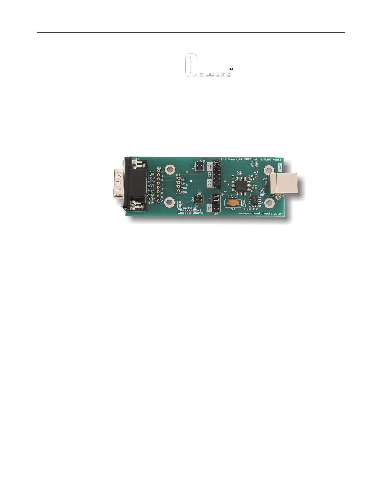
3. Board layout
1. D-type E-blocks connector
2. Patch system
3. Rx / tx jumper selection
4. RTS/CTS jumper system
5. FT232BL chip
6. EEPROM with USB ID
7. USB socket
EB039-74-1.cdr

E-blocks
TM
USB232 board
Document code: EB039-30-1
4. Testing this product
The following program will test the circuit. The test files can be downloaded from www.matrixmultimedia.com
The following instructions explain the steps to test your USB232 board. The instructions assum e tha t PPP is
installed and functional. It also assumes that you are confident in sending a program to the PIC via the
Multiprogrammer.
These programs require a PICmicro Multiprogrammer board (EB-006) with a 40-pin PIC16F877A device. They
require a PC with FTDI drivers installed, MP rog 2.3 software, a spare USB port and Hyperterminal.
The program will enable you to fully test the func tionality of the board.
System Setup
Multi-programmer board (EB006) with:
EB006 Options Setting
Power supply External, 14V
PICmicro device 16F877A
SW1 (Fast/Slow) Don’t care
SW2 (RC/Xtal) Xtal
Xtal frequency 19.6608MHz
Port A Switch board EB007
Port B LCD display EB005
Port C USB232 board
EB039
Port D
Port E
Test program power.hex
EB005 Options Setting
DEFAULT
EB039 Options Setting
J5, J3 A
J6, J4 1
Connect “+V” from the Screw terminal of the Switch board, and LCD board to “+V” of the Multiprogramm er
.
PC software setup for the test routine
1. Plug the EB03 9 US B232 E-Bloc k into the PC using a US B cable. If this is the first time the device is being plug ged in,
the “Add new hardware” wizard m ay appear. If it does, you will need to instal l the appropriate drivers - see the separate
“Driver Installation” document for guidance.
2.
The first step is to determine which virtual COM port has been alloc a ted to the de vic e. Do this by clicki ng on the “Start”
button and selecting “Run…” In the “Open:” box, type “devmgmt.msc” (without the quotes) and press “OK” – this will
open the “Device Manager” wind ow.
3.
Locate the “Ports (COM & LPT)” section and expand it by clicking the “+” symbol. The allocated COM port number
will be shown in brackets after the “USB232 E-Block” entry.
4.
Close down the “Device Manager” window.
5.
Open “HyperTerminal”. Enter a name in “Conne ction Description” window if this appears – it does not matter what you
enter here.
6.
In the “Connect to…” window, select t he appropriate COM port number from the “Connect using:” drop-down box.
7.
Set the properties for this connection to the following:
•
Bits per second = 9600
•
Data bits = 8
•
Parity = None

E-blocks
TM
USB232 board
Document code: EB039-30-1
• Stop bits = 1
•
Flow control = Hardware
The connection should now be active. Press (disconnect) button.
8.
Test Procedure
1. Press “reset” on the Multiprogrammer – the LCD display should read “EB039 test” and “Press A0”.
2.
Plug the USB32 board into the PC using the USB cable (if it is not already connec ted).
3. Click the (connect) button in HyperTerminal.
If you get the “Unable to connect to COMx…” message, click the properties button ( ) and in the “Connect using”
4.
drop-down, select the appropriate COM port. This will probably increment after each unit has been tested, so it is likely
that you need to select the highes t COM port number. Click “OK” and then click the connect button again – this time
there should be no error message.
5.
Press A0 on the Switches E-Block – HyperTerminal should display the message “EB039 Test” and the LCD display
should display “Waiting for PC..”
6.
Type a few characters into the HyperTerm inal window – whatever you typed should be displayed on the lower part of the
LCD display (and not on the PC window).
7.
Press <return> on the PC keyboard and the LCD display (and HyperTermina l) shou ld rea d “**U nit Passed* *” . After a
couple of seconds, the LCD display will revert to the original message.

E-blocks
Document code: EB039-30-1
TM
USB232 board
5. Circuit description
The circuit on the EB039 is made up o f a FTDI FT232BL device and associated EEPROM, and a patch system
linking the FT232BL to the upstream board.
FT232BL
The FT2323BL is a single chip device that allows asynchronous data transfer between a computer with a USB port
and your hardware project. The device supports a range of data transfer protocols based on RS232 like signals (TTL
voltage levels) which allows data transfer at rates up to 3M baud.
The device connects to the USART of a microcontroller using the TX, RX, CTS and RTS lines via a patch system
(see below).
On the PC (Windows, Linux or MAC), there are 2 types of drivers available. The first provide a “virtual” COM port
functionality, which will allow legacy serial port applications to access the USB232 E-Block as if it was connected
to a standard serial COM port. These are known as Virtual COM Port (of VCP) driver s.
The second set of drivers (known as D 2XX drivers) provide direct access to the i/o li nes of the FT232BL device.
These provide a faster communication speed and al low for more flexibility in your design.
EEPROM
There is an EEPROM on the EB-039 E-Block, which is used to store information that identifies the board as a USB
device. This EEPROM also contains a unique serial number.
Patch system
The D type plug, J2 is used to connect the USB232 board to your E-blocks system. As with most E-blocks
downstream boards the patch sys tem allows you to pre-select the conne ctions between the key signals on the board
and the upstream board. Many E-blocks systems are optimized for the PICmicro range of devices but the key
signals, TX and RX, are on different pins for different PICmicro devices. The followin g table shows you the TX and
RX connections for several PICmicro devices:
Table of pin outs of various chip families
Chip signal port bit D-type pin
16F88 RX RB2 pin 3
TX RB5 pin 6
16F627a RX RB1 pin 2
TX RB2 pin 3
16F877a RX RC7 pin 8
TX RC6 pin 7
The jumpers A, B, C allow you to quickly configure RX and TX for several ranges of PICmicro device. If you are
not using one of the devices in the table then you will need to select jumper D to make your own configuration.
This is achieved by identifying the USART pins on the PICmicro, the n by selecti ng the corre spo ndi n g links be tw een
the USB232 board and the upstream device.

E-blocks
TM
USB232 board
Document code: EB039-30-1
Jumper
Setting
A
Jumper Setting
B
PIC16F devices PIC16C devices
Jumper Setting
C
Jumper Setting
D
PIC16F87 PIC16F627/A PIC16F73 PIC16C63 PATCH
SYSTEM
PIC16F88 PIC16F628/B PIC16F737 PIC16CR63
PIC16F648A PIC16F74 PIC16C65/A/B
PIC16F746 PIC16RC65
PIC16F76 PIC16C66
PIC16F767 PIC16C73/A/B
PIC16F77 PIC16C74/A/B
PIC16F777 PIC16C745
PIC16F870/1 PIC16C765
PIC16F873/A PIC16C77
PIC16F874/A PIC16C773
PIC16F876/A PIC16C774
PIC16F877/A PIC16C774
Table 1. Jumper settings for TX and RX selection.
Jumper settings 1, 2, and 3 are used to set the correct pins for CTS and RTS. The following tables illustrate the
correct jumper settings.
Jumper Setting
1
Jumper Setting
2
Jumper Setting
3
CTS RTS CTS RTS CTS RTS
Bit 4 Bit 0 Bit 5 Bit 4 Patch Patch
Table 2. Jumper settings for RTS and CTS selection
(NOTE: Jumper setting 2 is used in conjunction with our Blueto oth module and should not be u s ed when the USB232 E-Bloc k is
connected to a microcontroller).

E-blocks
TM
USB232 board
Document code: EB039-30-1
Appendix 1
 Loading...