

Page 1

E 7 X - 0 3 S U S P E N S I O N E L L I P T I C A L
S E R V I C E M A N U A L
Page 2

TABLE OF CONTENTS
CHAPTER 1: SERIAL NUMBER LOCATION ........................................................... 1
CHAPTER 2: IMPORTANT SAFETY INSTRUCTIONS
2.1 Moving the Unit ........................................................................................................... 3
2.2 Electrical Requirements ............................................................................................. 4
CHAPTER 3: PREVENTATIVE MAINTENANCE
3.1 Recommended Cleaning Tips .................................................................................... 5
3.2 Check for Damaged Parts ......................................................................................... 5
3.3 Care and Maintenance Instructions ........................................................................... 6
CHAPTER 4: CONSOLE OVERLAY AND WORKOUT DESCRIPTION
4.1 Console Description ................................................................................................... 7
4.2 Workout Setup Steps - Manual ................................................................................... 8
4.3 Workout Setup Steps - Fat Burn ................................................................................. 8
4.4 Workout Setup Steps - Training Workouts .................................................................. 8
4.5 Workout Setup Steps - Cooper Fitness Test ............................................................... 9
4.6 Workout Setup Steps - Target Heart Rate .................................................................. 10
4.7 Workout Setup Steps - Constant Watts ...................................................................... 10
CHAPTER 5: MANAGER MODE
5.1 Manager Mode Overview ............................................................................................ 11
5.2 Manager Mode - About Tab......................................................................................... 11
5.3 Manager Mode - Time Tab .......................................................................................... 12
5.4 Manager Mode - Defaults Tab..................................................................................... 12
5.5 Manager Mode - Language Tab .................................................................................. 13
5.6 Manager Mode - TV Tab ............................................................................................. 14
5.7 Manager Mode - Other Tab ......................................................................................... 14
CHAPTER 6: ENGINEERING MODE
6.1 Engineering Mode Overview ....................................................................................... 15
6.2 Engineering Mode - Errors Tab ................................................................................... 15
6.4 Engineering Mode - Statistics Tab .............................................................................. 16
6.5 Engineering Mode - Self Power Tab ........................................................................... 16
6.6 Engineering Mode - Clubs Tab.................................................................................... 17
6.7 Engineering Mode - Club ID Tab ................................................................................. 17
CHAPTER 7: SERVICE MODE
7.1 Service Mode Overview .............................................................................................. 18
7.2 Service Mode - Setup Tab........................................................................................... 19
7.3 Service Mode - Test Tab ............................................................................................. 21
7.4 Service Mode - Date / Time Tab ................................................................................. 22
7.5 Service Mode - Log Tab .............................................................................................. 23
CHAPTER 8: TROUBLESHOOTING
8.1 Electrical Diagram ...................................................................................................... 24
8.2 Error Codes on the Console ...................................................................................... 27
8.3 LCB LED Indicators .................................................................................................... 28
8.4 Troubleshooting - Display Issues ................................................................................ 29
8.5 Troubleshooting - Error 0x04A0 .................................................................................. 30
8.6 Troubleshooting - Resistance Issues .......................................................................... 31
8.7 Troubleshooting - Pedals Slipping .............................................................................. 32
8.8 Troubleshooting - Noise Issues................................................................................... 32
8.9 Troubleshooting - Heart Rate Issues .......................................................................... 33
8.10 Troubleshooting - No Power to the Console ............................................................... 34
8.11 TV Troubleshooting - Overview ................................................................................... 35
Page 3

TABLE OF CONTENTS
CHAPTER 9: PART REPLACEMENT GUIDE
9.1 Front Disk Replacement ............................................................................................ 36
9.2 Front Shroud Replacement ......................................................................................... 37
9.3 Lower Control Board (LCB) Replacement .................................................................. 40
9.4 Generator Replacement .............................................................................................. 41
9.5 Generator Belt Replacement ...................................................................................... 43
9.6 Drive Belt Replacement .............................................................................................. 44
9.7 Pulley Axle Set Replacement ...................................................................................... 45
9.8 Drive Axle Set Replacement ....................................................................................... 46
9.9 Crank Replacement .................................................................................................... 50
9.10 Console Replacement ................................................................................................. 51
9.11 Overlays & Keypads Replacement ............................................................................. 52
9.12 Console Mast Handlebar Replacement ...................................................................... 54
9.13 Dual Action Handlebar Replacement .......................................................................... 55
9.14 Foot Pedals Replacement ........................................................................................... 56
9.15 Pedal Arm Replacement ............................................................................................. 57
9.16 Link Arm Replacement ................................................................................................ 58
9.17 Swing Arm Replacement ............................................................................................. 59
9.18 Vertical Stabilizer Arm Replacement ........................................................................... 60
9.19 Incline Arm Cover Replacement ................................................................................. 61
9.20 Handlebar Service ....................................................................................................... 62
9.21 Testing the Suspension Elliptical ................................................................................. 63
CHAPTER 10: SUSPENSION ELLIPTICAL SPECIFICATIONS AND ASSEMBLY GUIDE
10.1 Suspension Elliptical Specifications ........................................................................... 64
10.2 Assembly Hardware .................................................................................................... 65
10.3 Suspension Elliptical Assembly Steps ....................................................................... 66
10.4 Leveling the Suspension Elliptical ............................................................................... 78
10.5 TV Programming Instructions ..................................................................................... 79
CHAPTER 11: SOFTWARE UPGRADE PROCEDURE
11.1 Software Upgrade Procedure ..................................................................................... 82
III
Page 4
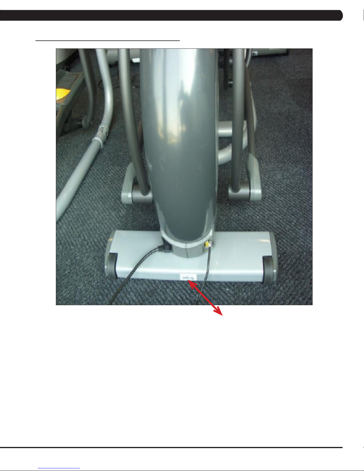
1.1 SERIAL NUMBER LOCATION
CHAPTER 1: SERIAL NUMBER LOCATION
SERIAL NUMBER LOCATION
1
Page 5
CHAPTER 1: SERIAL NUMBER LOCATION
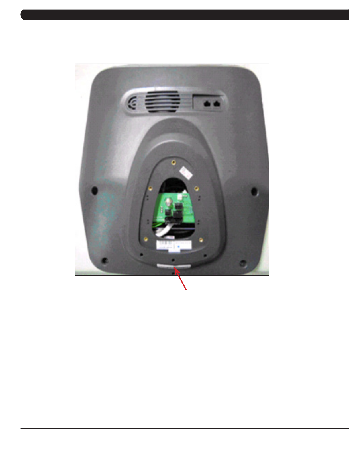
1.1 SERIAL NUMBER LOCATION - CONTINUED
CONSOLE SERIAL NUMBER LOCATION
2
CONSOLE SERIAL NUMBER LOCATION
Page 6

CHAPTER 2: IMPORTANT SAFETY INSTRUCTIONS
2.1 READ AND SAVE THESE INSTRUCTIONS
This Suspension Elliptical is intended for commercial use. To ensure
your safety and protect the equipment, read all instructions before
operating the MATRIX Suspension Elliptical.
When using an electrical product, basic precautions should always be
followed including the following:
• Anapplianceshouldneverbeleftunattendedwhenplugged
in. Unplugtheunitfromtheoutletwhennotinuseandbefore
puttingonortakingoffanyparts.
• Thisproductmustbeusedforitsintendedpurpose
describedinthisservicemanual. Donotuseother
attachmentsthatarenotrecommendbythemanufacturer.
Attachmentsmaycauseinjury.
• Topreventelectricalshock,neverdroporinsertanyobject
intoanyopening.
• Donotremovetheconsolecovers.Serviceshouldonlybe
donebyanauthorizedservicetechnician.
• Donotcarrythisunitbyit’ssupplycordorusethecordas
ahandle.
• ClosesupervisionisnecessarywhentheSuspension
Ellipticalisusedbyornearchildrenordisablepersons.
• Donotuseoutdoors.
• Donotoperatewhereaerosol(spray)productsarebeing
usedorwhenoxygenisbeingadministered.
CAUTION! Ifyouexperiencechestpains,nausea,dizziness,or
shortnessofbreath,stopexercisingimmediatelyandconsult
yourphysicianbeforecontinuing.
CAUTION! Anychangesormodificationstothisequipment
couldvoidtheproductwarranty.
• Todisconnect,turnallcontrolstotheoffposition,then
removetheplugfromtheoutlet.
• Donotusetheequipmentinanywayotherthandesignedor
intendedbythemanufacturer.ItisimperativethatallMatrix
FitnessSystemsequipmentisusedproperlytoavoidinjury.
• Keephandsandfeetclearofmovingpartsatalltimesto
avoidinjury.
• Unsupervisedchildrenmustbekeptawayfromthisequip
ment.
• Donotwearlooseclothingwhileontheequipment.
3
Page 7

CHAPTER 2: IMPORTANT SAFETY INSTRUCTIONS
2.2 ELECTRICAL REQUIREMENTS
The Matrix Suspension Elliptical can now be self powered. It is recommended that the unit be plugged in for at least 4 hours after initial
installation to charge the battery prior to using the self powered feature. NOTE: If an add on TV (using a bracket) or Virtual Active is added to
the unit, it must be plugged in, or the TV or VA will not operate correctly. If the Suspension Elliptical will be plugged in, follow the requirements
below.
MATRIX DEDICATED CIRCUIT / ELECTRICAL REQUIREMENT INFO
All powered Matrix Suspension Ellipticals require the use of a 15 amp or 20 amp “dedicated circuit,” with a non-looped (isolated) neutral/ground,
for the power requirement. Quite simply this means that each outlet you plug Suspension ellipticals into should not have anything else running
on that same circuit besides other Suspension ellipticals (up to 3 per 15 amp circuit and 4 per 20 amp circuit). The easiest way to verify this is
to locate the main circuit breaker box, and turn off the breaker(s) one at a time. Once a breaker has been turned off, the only thing that should
not have power to it are the Suspension ellipticals in question. No lamps, vending machines, fans, sound systems, or any other item should lose
power when you perform this test.
Non-looped (isolated) neutral/grounding means that each circuit must have an individual neutral/ground connection coming from it, and terminating
at an approved earth ground. You cannot “jumper” a single neutral/ground from one circuit to the next.
In addition to the dedicated circuit requirement, the proper gauge wire must be used from the circuit breaker box, to each outlet that will have the
maximum number of units running off of it. If the distance from the circuit breaker box, to each outlet, is 100 ft or less, then 12 gauge wire may be
used. For any distance greater than 100 ft from the circuit breaker box to the outlet, 10 gauge wire must be used.
For your safety and Suspension Elliptical performance, the ground on this circuit must be non-looped. Please refer to NEC article 210-21 and 210-23.
Your Suspension elliptical is provided with a power cord with a plug listed below and requires the listed outlet. Any alterations of this power cord
could void all warranties for this product. Multiple Suspension Ellipticals can be powered on one dedicated circuit. (3 units per 15 Amp and 4 units
per 20 Amp dedicated circuit.)
GROUNDING INSTRUCTIONS:
The Matrix E7x-03 Suspension Elliptical must be grounded. If it should malfunction or break down, grounding provides a path of least resistance
for electric current to reduce the risk of electric shock. The Suspension Elliptical is equipped with a cord having an equipment grounding
conductor and a grounding plug. The plug must be plugged into an appropriate outlet that is properly installed and grounded in accordance with
all local codes and ordinances. If the user does not follow these grounding instructions, the user could void the Matrix limited warranty.
DANGER: Improper connection of the equipment grounding conductor can result in the risk of electric shock. Check with a qualified electrician
if the user is in doubt as to whether the product is properly grounded. Do not modify the plug provided with the product if it will not fit the outlet,
have a proper outlet installed by an electrician.
CONSOLE POWER
The Matrix Suspension Elliptical console has a battery that makes it self powered. This means that even if the unit is not plugged in, the
console may still have power for up to 12 hours. If the console power needs to be reset or turned off, press and hold the CHANNEL UP and
CHANNEL DOWN keys for 3-5 seconds until the console turns off. The console power will also need to be reset if settings are changed in
Manager, Engineering, or Service Modes.
4
Page 8

CHAPTER 3: PREVENTATIVE MAINTENANCE
3.1 RECOMMENDED CLEANING TIPS
Preventative maintenance and daily cleaning will prolong the life and
look of your MATRIX Suspension Elliptical.
Please read and follow these tips.
• Positiontheequipmentawayfromdirectsunlight.TheintenseUV
light can cause discoloration on plastics.
• Locateyourequipmentinanareawithcooltemperaturesandlow
humidity.
• Cleanwithasoft100%cottoncloth.
• Cleanwithsoapandwaterorothernon-ammoniabasedallpur-
pose cleaners.
• Wipefootpads,handles,heartrategrips,andhandlebarsclean
after each use.
• Donotpourliquidsdirectlyontoyourequipment.Thiscancause
damage to the equipment and in some cases electrocution.
• Checkpedalmotionandstability.
• Adjustlevelingfeetwhenequipmentwobblesorrocks.
• Maintainacleanareaaroundequipment,freefromdustanddirt.
3.2 CHECK FOR DAMAGED PARTS
DO NOT use any equipment that is damaged or has worn or broken
parts. Use only replacement parts supplied by Matrix Fitness
Systems.
MAINTAIN LABELS AND NAMEPLATES. Do not remove labels
for any reason. They contain important information. If unreadable or
missing, contact Matrix Fitness Systems for a replacement. 1-866693-4863, www.matrixfitness.com
MAINTAIN ALL EQUIPMENT Preventative maintenance is the key
to smooth operating equipment. Equipment needs to be inspected
at regular intervals. Defective components must be replaced
immediately. Improperly working equipment must be kept out of use
until it is repaired. Ensure that any person(s) making adjustments
or performing maintenance or repair of any kind is qualified to do
so. Matrix Fitness Systems will provide service and maintenance
training at our corporate facility upon request or in the field if proper
arrangements are made.
5
Page 9

CHAPTER 3: PREVENTATIVE MAINTENANCE
3.3 CARE AND MAINTENANCE INSTRUCTION
In order to maximize life span, and minimize down time, all MATRIX equipment requires regular cleaning, and maintenance items performed on
a scheduled basis. This section contains detailed instructions on how to perform these items, the frequency of which they should be done, and a
check list to sign off each time service is completed for a specific machine. Some basic tools and supplies will be necessary to perform these tasks
which include (but may not be limited to):
* Metric Allen wrenches
* #2 Phillips head screwdriver
* Adjustable wrench
* Torque wrench (capability to read foot lbs, and inch lbs)
* Lint free cleaning cloths
* Mild, water soluble, detergent – such as “Simple Green”, or other Matrix approved product
* Teflon based spray lubricant such as “Super Lube”, or other Matrix approved product
* Vacuum cleaner with an extendable hose and crevasse tool attachment
You may periodically see addendums to this document, as the Matrix Technical Support Team identifies items that require specific attention, the
latest version will always be available on the Matrix web site, www.matrixfitness.com
DAILY MAINTENANCE ITEMS
1) Look and listen for loose fasteners, unusual noises, and any other indications that the equipment may be in need of service.
2) Clean the Suspension Elliptical before and after each use, including:
a. Use a damp, soft cloth with water or mild liquid detergent to clean all exposed surfaces. DO NOT use ammonia, chlorine, or any acid
based cleaners. NOTE: Never spray cleaner directly on the equipment. Spray the cleaner directly into a cloth to clean.
b. Keep the console display free of fingerprints and salt build up caused by sweat.
c. Frequently vacuum the floor beneath the unit to prevent the accumulation of dust and dirt which can affect the smooth operation of the
unit.
3) Attempt to wobble the unit back and forth, level if needed (see Section 10.4).
WEEKLYMAINTENANCEITEMS
1) Wipe down the roller track and wheels with a cotton cloth to remove any debris that may be present.
MONTHLY MAINTENANCE ITEMS
1) Inspect the console, handrails, link arms, pedal arms, and pedals for damage.
2) Check the link / pedal arms for loose joints, tighten hardware as needed.
3) Adjust leveling feet if the equipment rocks or wobbles.
4) Check the pedal foot pad for damage or wear. Replace as needed. Vacuum under the rubber foot pad.
QUARTERLY MAINTENANCE ITEMS
1) Remove the front shrouds and check belts for damage, alignment, and proper tension.
2) Remove the plastic covers where the handlebar and link arms are connected. Lubricate the ball joint with your finger by applying grease to
the ball bearing.
6
Page 10
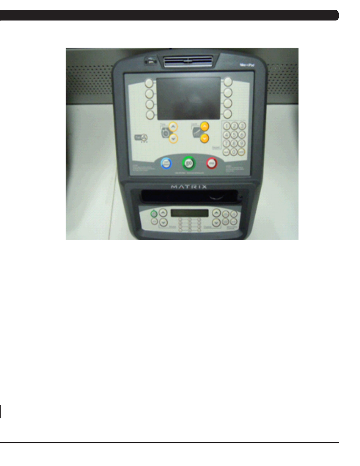
CHAPTER 4: CONSOLE OVERLAY AND WORKOUT DESCRIPTION
4.1 CONSOLE DESCRIPTION
MULTI-PURPOSEKEYS: Keys have different functions depending on
each screen.
GO: One touch Start.
ENTER: To confirm each program setting.
UP / DOWN LEVEL: Easy information and level selection.
UP / DOWN TIME: Easy information and time adjustment.
STOP: Ends workout and shows workout summary data.
NUMBERKEYPAD: Workout data input for workout setup. Level
adjustment during workout.
COOL DOWN: Puts the Suspension Elliptical into Cool Down Mode.
FAN: Allows for fan speed selection (fan has 3 operating speeds).
E7X-03 ENTERTAINMENT ZONE
IPOD®: Will take the user directly to the iPod screen to allow for iPod
control and play list selection.
VOLUME UP / DOWN: Adjusts the volume output through the
headphone jack of either integrated console TV or iPod output.
NUMBERKEYPAD: Allows for easy TV channel selections.
CHANNEL UP / DOWN: Allows for channel selection.
DISPLAY MODE: Allows user to cycle through console display options,
iPod, TV, or profile display.
LAST CHANNEL: Allows the user to cycle between the current
channel and the previous channel they were viewing.
7
Page 11

CHAPTER 4: CONSOLE OVERLAY AND WORKOUT DESCRIPTION
4.2 WORKOUT SETUP STEPS - MANUAL 4.4 WORKOUT SETUP STEPS - TRAINING WORKOUTS
GO - Press to immediately begin a workout. Workout, resistance
level, and time will automatically go to default settings. Pressing
GO will not prompt user for age, weight, or level settings.
1) Start pedaling and press the GO key to begin your workout. 2)
The display will read 3, 2, 1, Begin and then the program will start.
MANUAL - Manual allows the user to input more information
while defining their own workout. Calorie expenditure will be more
accurate when inputting information in Manual than by pressing GO.
1) Start pedaling and press the key next to MANUAL on the
display.
2) Select the key next to Level and follow the prompts to set.
3) Select the key next to Time and follow the prompts to set. .
4) Select the key next to Weight and follow the prompts to set.
5) Select the key next to GO and the display will read 3, 2, 1, and
then the program will begin.
4.3 WORKOUT SETUP STEPS - FAT BURN
FAT BURN - Fat burn is a level based program that is designed
to help users burn fat through various resistance level changes.
1) Start pedaling and press the key next to FAT BURN on the
display.
2) Select the key next to Level and follow the prompts to set.
3) Select the key next to Time and follow the prompts to set. .
4) Select the key next to Weight and follow the prompts to set.
5) Select the key next to GO and the display will read 3, 2, 1, and
then the program will begin.
ROLLING HILLS - The Rolling Hills program is a level based program
that automatically adjusts the resistance level to simulate real terrain.
1) Start pedaling and press the key next to TRAINING WORKOUTS on
the display, and then press the key next to ROLLING HILLS.
2) Select the key next to Level and follow the prompts to set.
3) Select the key next to Time and follow the prompts to set. .
4) Select the key next to Weight and follow the prompts to set.
5) Select the key next to GO and the display will read 3, 2, 1, and then
the program will begin.
INTERVALS - The Intervals program is a level based program that
automatically adjusts the resistance of the machine from low to high
intensity settings at regular intervals.
1) Start pedaling and press the key next to TRAINING WORKOUTS on
the display, and then press the key next to INTERVAL TRAINING.
2) Select the key next to Level and follow the prompts to set.
3) Select the key next to Time and follow the prompts to set. .
4) Select the key next to Weight and follow the prompts to set.
5) Select the key next to GO and the display will read 3, 2, 1, and then
the program will begin.
RANDOM - Random is a level based workout that randomly adjusts the
resistance of the machine.
1) Start pedaling and press the key next to TRAINING WORKOUTS on
the display, and then press the key next to RANDOM.
2) Select the key next to Level and follow the prompts to set.
3) Select the key next to Time and follow the prompts to set. .
4) Select the key next to Weight and follow the prompts to set.
5) Select the key next to GO and the display will read 3, 2, 1, and then
the program will begin.
8
Page 12

CHAPTER 4: CONSOLE OVERLAY AND WORKOUT DESCRIPTION
4.5 WORKOUT SETUP STEPS - COOPER FITNESS TEST
FITNESS TEST -The Cooper Fitness Test measures cardiovascular fitness and proves an estimated sub-maximal VO2 result. It is based
on power output according to ACSM standards and was developed by the Cooper Institute© (www.cooperinstitute.org). User RPMs must
remain between 60-80 RPM during the test. The test will end when the user can no longer maintain this speed. Use of a heart rate strap is
optional but provides more data.
The test starts at a low intensity level and gradually increases in intensity (difficulty) every 2 minutes. As it increases, the user must maintain
60-80 RPM to advance to the next level. The test could take upwards of 30+ minutes for very fit individuals. Once the test ends a recovery
period (cool down) will begin and the user's results are calculated and displayed. Results are based on the number of stages completed.
Incline will not be adjustable during the test.
1) Start pedaling and press the key next to FITNESS TEST on the display.
2) Select the key next to Age and follow the prompts to set.
3) Select the key next to Gender and follow the prompts to set. .
4) Select the key next to Weight and follow the prompts to set.
5) Select the key next to GO and the display will read 3, 2, 1, and then the program will begin.
6) Once the workout is complete, the display will read the results of the Fitness Test.
STAGE COMPLETE:
1 Well Below Average
2 Well Below Average
3 Below Average
4 Below Average
5 Average
6 Average
7 Above Average
8 Above Average
9+ Well Above Average
9
Page 13
CHAPTER 4: CONSOLE OVERLAY AND WORKOUT DESCRIPTION
4.6 WORKOUT SETUP STEPS - TARGET HEART RATE 4.7 WORKOUT SETUP STEPS - CONSTANT WATTS
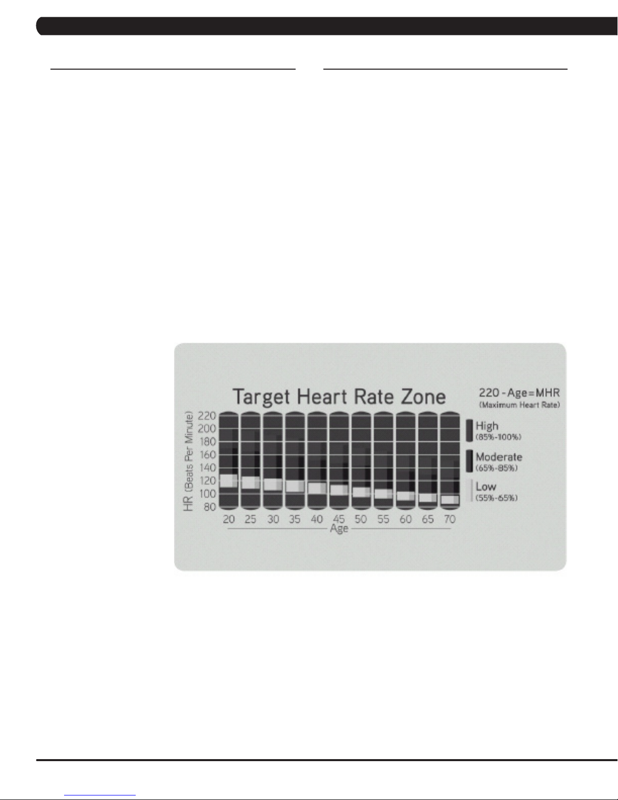
TARGET HEART RATE - The Matrix Suspension Elliptical
comes with standard digital contact heart rate sensors and are
POLAR telemetry compatible. The heart rate control workout mode
allows the user to program their desired heart rate zone, and the
Suspension Elliptical will automatically adjust the level based upon
the user's heart rate. The heart rate zone is calculated using the
followingequation:(220-Age)8%=targetheartratezone.Theuser
must wear a POLAR telemetric strap or continually hold onto the
contact heart rate grips for this workout.
Locate the metal sensors on the handlebars of the Suspension
Elliptical. Notice that there are two separate pieces of metal on
each grip. You must be making contact with both pieces of each
grip to get an accurate heart rate reading. You can grab these
sensors in any program to view your current heart rate.
1) Start pedaling and press the key next to TARGET HEART RATE
on the display.
2) Select the key next to Age and follow the prompts to set.
2) Select the key next to Percent of HR and follow the prompts to
set.
3) Select the key next to Time and follow the prompts to set. .
4) Select the key next to Weight and follow the prompts to set.
5) Select the key next to GO and the display will read 3, 2, 1, and
then the program will begin.
CONSTANT WATTS - Constant Watts is a unique program
that allows you to vary your cadence or RPM and the Suspension
Elliptical's resistance level will adjust accordingly to your selected
goal. The quicker you pedal, the less resistance for the goal
selected.
1) Start pedaling and press the key next to CONSTANT WATTS
on the display.
2) Select the key next to Watts and follow the prompts to set.
3) Select the key next to Time and follow the prompts to set. .
4) Select the key next to Weight and follow the prompts to set.
5) Select the key next to GO and the display will read 3, 2, 1, and
then the program will begin.
10
Page 14
CHAPTER 5: MANAGER MODE
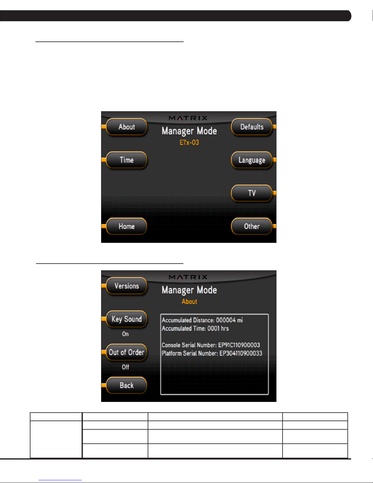
5.1 MANAGER MODE OVERVIEW
The Manager's Custom Mode allows the club owner to customize the Suspension Elliptical for the club.
1) To enter Manager Mode, press ENTER, 1, 0, 0, 1, ENTER on the upper display. Manager Mode will appear on the display (Figure A).
2) Select the key next to the setting that needs to be changed, and follow the prompts to change.
3) Press the ENTER key once the desired setting is correct to save.
4) Press HOME or press and hold the STOP key for 3-5 seconds to return to normal operation. NOTE: If a setting has been changed, the
unit and console power should be reset. Cycle the power switch, and press and hold the CHANNEL UP and CHANNEL DOWN keys for 3-5
seconds to reset the console power.
5.2 MANAGER MODE - ABOUT TAB
MANAGER MODE
About
FUNCTION & DEFAULTS DESCRIPTIONS MODIFIED
Versions Software version. Cannot be modified.
Key Sound
Default: On
Out of Order
Default: Off
FIGURE A
Controls whether there is a key sound when a key is
pressed and whether it is a beep or through the speakers.
This option allows the club to put the console into an "out of
order" status.
On / Off
On / Off
11
Page 15
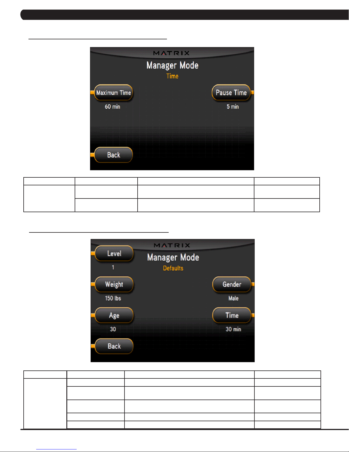
5.3 MANAGER MODE - TIME TAB
CHAPTER 5: MANAGER MODE
MANAGER MODE
Time
5.4 MANAGER MODE - DEFAULTS TAB
FUNCTION & DEFAULTS DESCRIPTIONS MODIFIED
Maximum Time
Default: 60 Minutes
Pause Time
Default: 5 Minutes
This option allows the club to set the maximum workout
duration limits during peak and non peak hours.
This option controls the default pause time. Maximum: 10 Minutes
Maximum: 99 Minutes
Minimum: 5 Minutes
Minimum: 1 Minute
MANAGER MODE
Defaults
FUNCTION & DEFAULTS DESCRIPTION MODIFIED
Level: Default: 1 This option controls the default program level. Max: 1 Min: 20
Age: Default: 30 This option controls the default user's age used in the target
Weight: Default: 150 lbs
/ 68 kg
Gender: Default: Male Setting the user as Male or Female. Male or Female
Time: Default: 30 Minutes This option controls the default program time. Max: Max Time Min: 5 Min
12
HR calculations.
This option controls the default weight used in the calorie
calculations. Displayed in pounds or kilograms.
Maximum: 100
Minimum: 10
Maximum: 400 lbs / 180 kg
Minimum: 80 lbs / 36 kg
Page 16

5.5 MANAGER MODE - LANGUAGE TAB
CHAPTER 5: MANAGER MODE
MANAGER MODE FUNCTION & DEFAULTS DESCRIPTIONS MODIFIED
Language Select default language. This option allows the user to select a flag for a
LANGUAGE
English
German
FLAG UNIT
Mile
Mile
KM
KM
KM
LANGUAGE
Spanish
Dutch
Italian
Japanese
specific language.
FLAG UNIT
KM
KM
KM
KM
KM
LANGUAGE
Chinese
Portuguese
French
N/A
FLAG UNIT
KM
KM
KM
KM
KM
13
Page 17
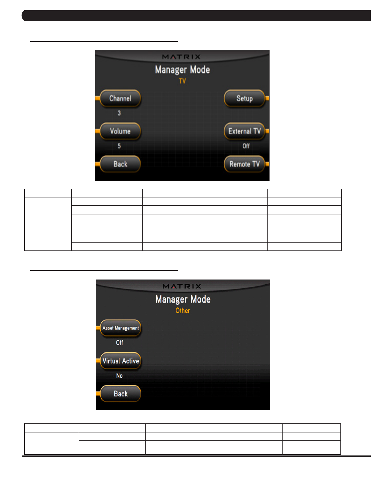
5.6 MANAGER MODE - TV TAB
CHAPTER 5: MANAGER MODE
MANAGER MODE
TV
5.7 MANAGER MODE - OTHER TAB
FUNCTION & DEFAULTS DESCRIPTIONS MODIFIED
Channel: Default: 3 This option controls the default TV channel on start up. Channels 1-999
Volume: Default: 5 This option controls the default TV volume on start up. Maximum: 17 Minimum: 1
Setup This option allows the TV to be programmed. Press -
External TV: Default: Off This option controls the external TV power. NOTE:
Remote TV Default: Off This option allows the controller to work with MYE TV. On/ Off
on the number keypad.
N/A
On / Off
The TV will only work in AC Plug in Mode.
MANAGER MODE
Other
FUNCTION & DEFAULTS DESCRIPTIONS MODIFIED
Asset Management This option allows the club to export machine data to a PC. Default: ON or OFF
Virtual Active This option controls the Virtual Active Function. NOTE: The
14
Virtual Active function will only work in AC Plug in Mode.
Default: Yes or No
Page 18
CHAPTER 6: ENGINEERING MODE
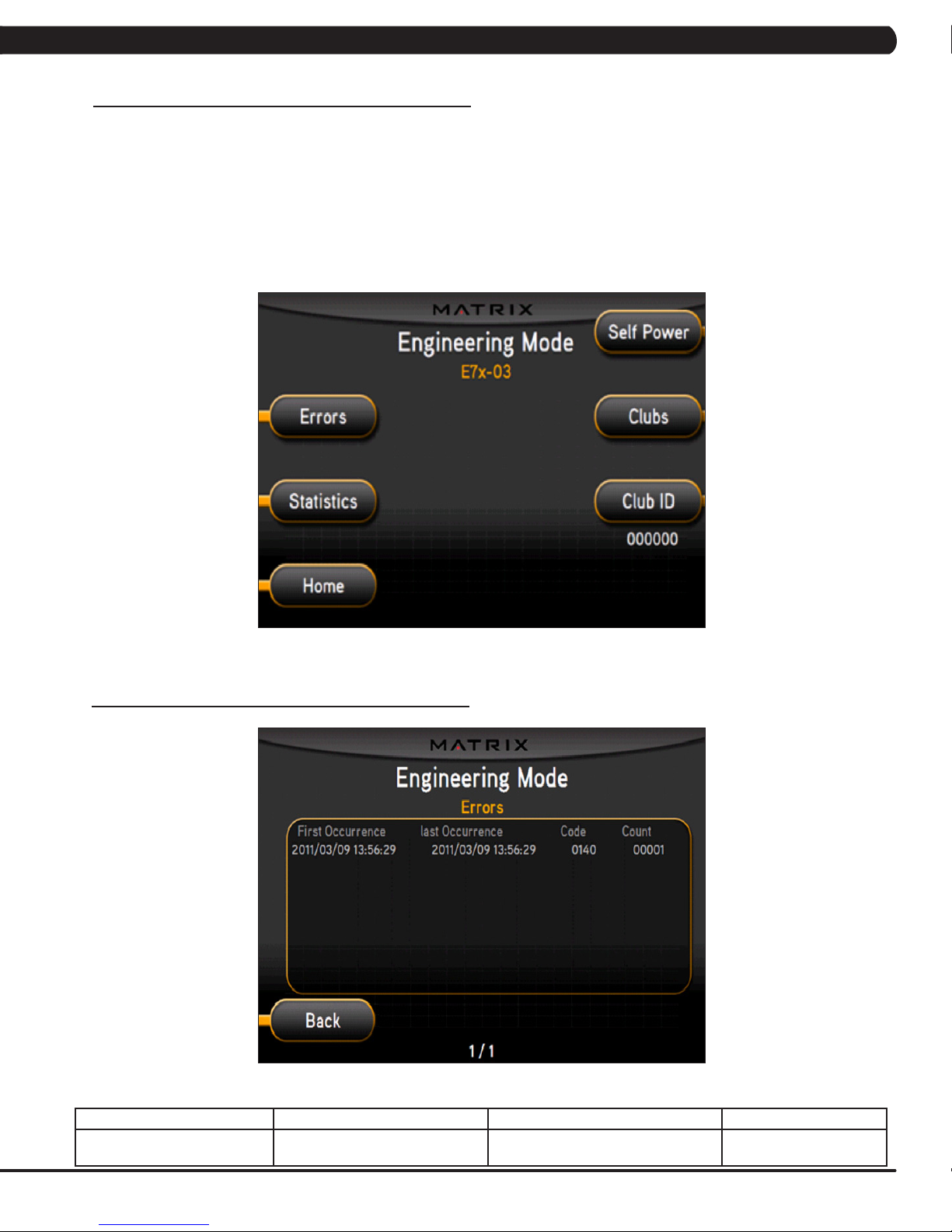
6.1 ENGINEERING MODE OVERVIEW
The Engineering Mode allows the club owner to keep track of the technical settings and error history for the Suspension Elliptical.
1) To enter Engineering Mode, press ENTER, 2, 0, 0, 1, ENTER on the upper display. Engineering Mode will appear on the display (Figure A).
2) Select the key next to the setting that needs to be changed, and follow the prompts to change.
3) Press the ENTER key once the desired setting is correct to save.
4) Press HOME or press and hold the STOP key for 3-5 seconds to return to normal operation. NOTE: If a setting has been changed, the unit
and console power should be reset. Cycle the power switch, and press and hold the CHANNEL UP and CHANNEL DOWN keys for 3-5 seconds to reset the console power.
6.2 ENGINEERING MODE - ERRORS TAB
FIGURE A
ENGINEERING MODE FUNCTION & DEFAULTS DESCRIPTIONS MODIFIED
Errors This option displays the error code
history.
N/A
15
Page 19
CHAPTER 6: ENGINEERING MODE
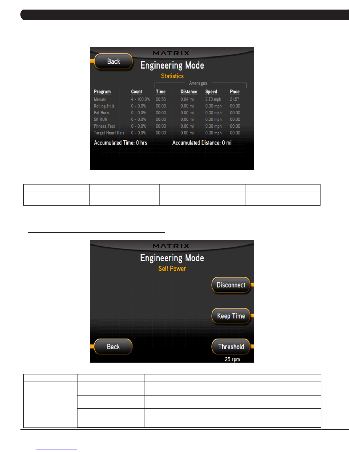
6.3 ENGINEERING MODE - STATISTICS TAB
ENGINEERING MODE FUNCTION & DEFAULTS DESCRIPTIONS MODIFIED
Statistics This option displays the workout
information for the unit.
6.4 ENGINEERING MODE - SELF POWER TAB
N/A
ENGINEERING MODE
Self Power
FUNCTION & DEFAULTS DESCRIPTIONS MODIFIED
Threshold
Default: 25 RPM
Disconnect This option controls the minimum RPM limit to
Keep Time This option controls how long the console keeps
16
This option controls the minimum RPM limits for
operation.
operate other functions when no power is present.
information after the minimum RPM threshold is not
met.
25 - 99 RPM
20 - 99 RPM
Home: 60 Seconds
Run: 30 Seconds
Summary: 30 Seconds
Page 20
CHAPTER 6: ENGINEERING MODE
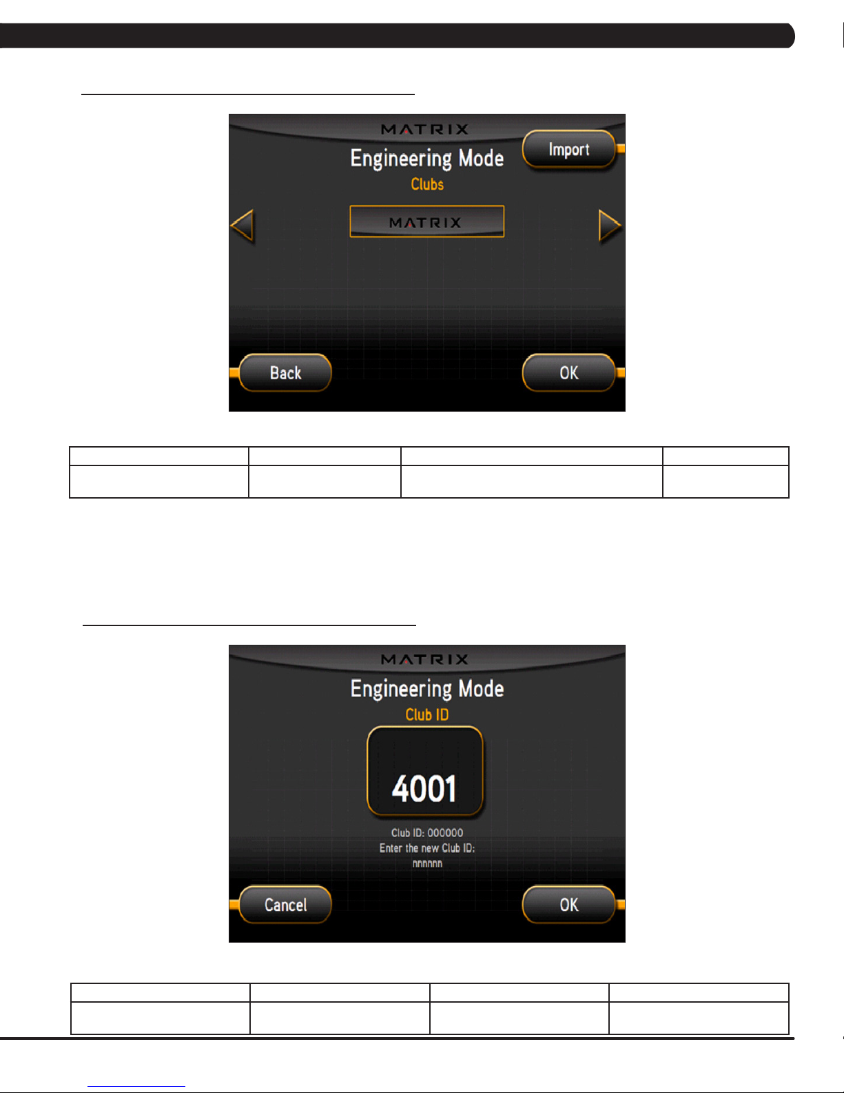
6.5 ENGINEERING MODE - CLUBS TAB
ENGINEERING MODE FUNCTION & DEFAULTS DESCRIPTIONS MODIFIED
Clubs
Default: MATRIX
6.6 ENGINEERING MODE - CLUB ID TAB
This option allows the club to select a screen
header from a list.
N/A
ENGINEERING MODE FUNCTION & DEFAULTS DESCRIPTIONS MODIFIED
Club ID This option records the Club ID of
the fitness facility.
N/A
17
Page 21
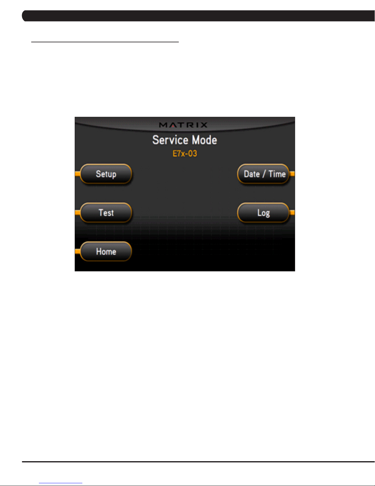
CHAPTER 7: SERVICE MODE
7.1 SERVICE MODE OVERVIEW
The Service Mode allows an authorized service provider to test and store information on the Suspension Elliptical.
1) To enter Service Mode, press ENTER, 3, 0, 0, 1, ENTER on the upper display. Service Mode will appear on the display (Figure A).
2) Select the key next to the setting that needs to be changed, and follow the prompts to change.
3) Press the ENTER key once the desired setting is correct to save.
4) Press HOME or press and hold the STOP key for 3-5 seconds to return to normal operation. NOTE: If a setting has been changed, the
unit and console power should be reset. Cycle the power switch, and press and hold the CHANNEL UP and CHANNEL DOWN keys for 3-5
seconds to reset the console power.
FIGURE A
18
Page 22
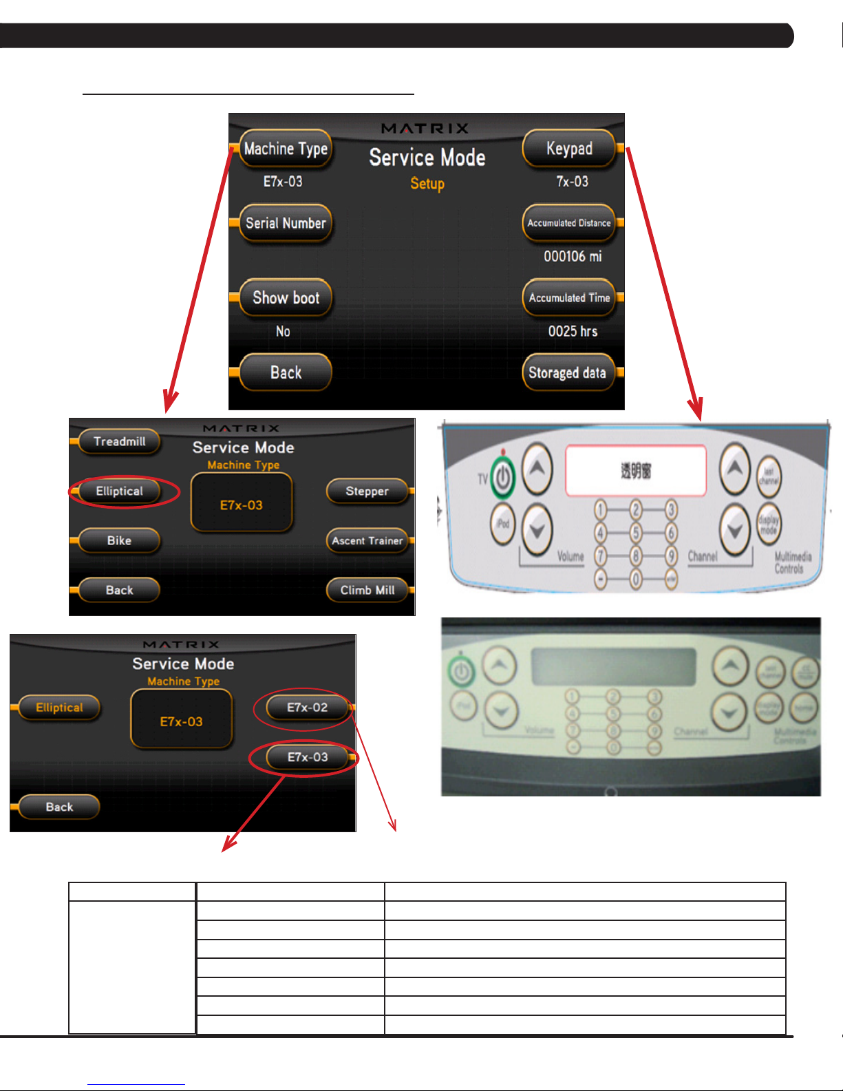
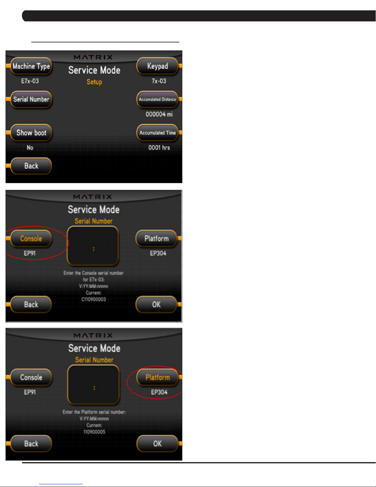
7.2 SERVICE MODE - SETUP TAB
CHAPTER 7: SERVICE MODE
SERVICE MODE
Setup
E7X-02 Keypad
E7X-03 Keypad
E7x-02-F - Elliptical Trainers should be set for this
model if rollers / tracks are present.
E7x-03-F - This refers to the suspension elliptical with no rollers / tracks present.
FUNCTION & DEFAULTS DESCRIPTIONS
Machine Type Default: Elliptical This option selects the current model. All EPs of this type should be set for -03.
Serial Number This option displays the serial number of the console and frame.
Accumulated Distance This option displays the accumulated workout distance since production.
Accumulated Time This option displays the accumulated workout time since production.
Show Boot Factory Setting Only.
Keypad This option allows the user to select the keypad type.
Storaged Data This option allows the workout data to be exported or imported via a USB.
19
Page 23
CHAPTER 7: SERVICE MODE
7.2 SERVICE MODE - SETUP TAB - CONTINUED
1) Enter into Service Mode (ENTER, 3, 0, 0, 1, ENTER).
2) Check if the Machine Type is set for E7x-03.
3) As long as the Machine Type is correct, the console should
automatically be set for EP91 and the platform should automatically
be set for EP304.
4) Input the serial number for the console first.
5) The serial number configuration is as follows, then press OK:
- V:YY:MM;nnnnn
- V is the version. This will be a letter between B-Z (if the
console is version A, just leave this blank).
- Y is the year (e.g. 10, 11, 12).
- MM is the month (e.g. 08, 09, 10).
- nnnnn is the actual serial number.
Repeat this procedure to enter the platform serial number.
6) The example shows the console automatically set for EP91 a
version of C, a year of 2011, a month of 09 (September), and a
serial number of 00003.
The example shows the platform automatically set for EP304, a
version of A, a year of 2011, a month of 09 (September), and a
serial number of 00005.
20
Page 24

7.3 SERVICE MODE - TEST TAB
CHAPTER 7: SERVICE MODE
Test
SERVICE MODE
FUNCTION & DEFAULTS DESCRIPTIONS
Keypad This option is for a keypad test.
Radio Test This option is for a radio test.
21
Page 25
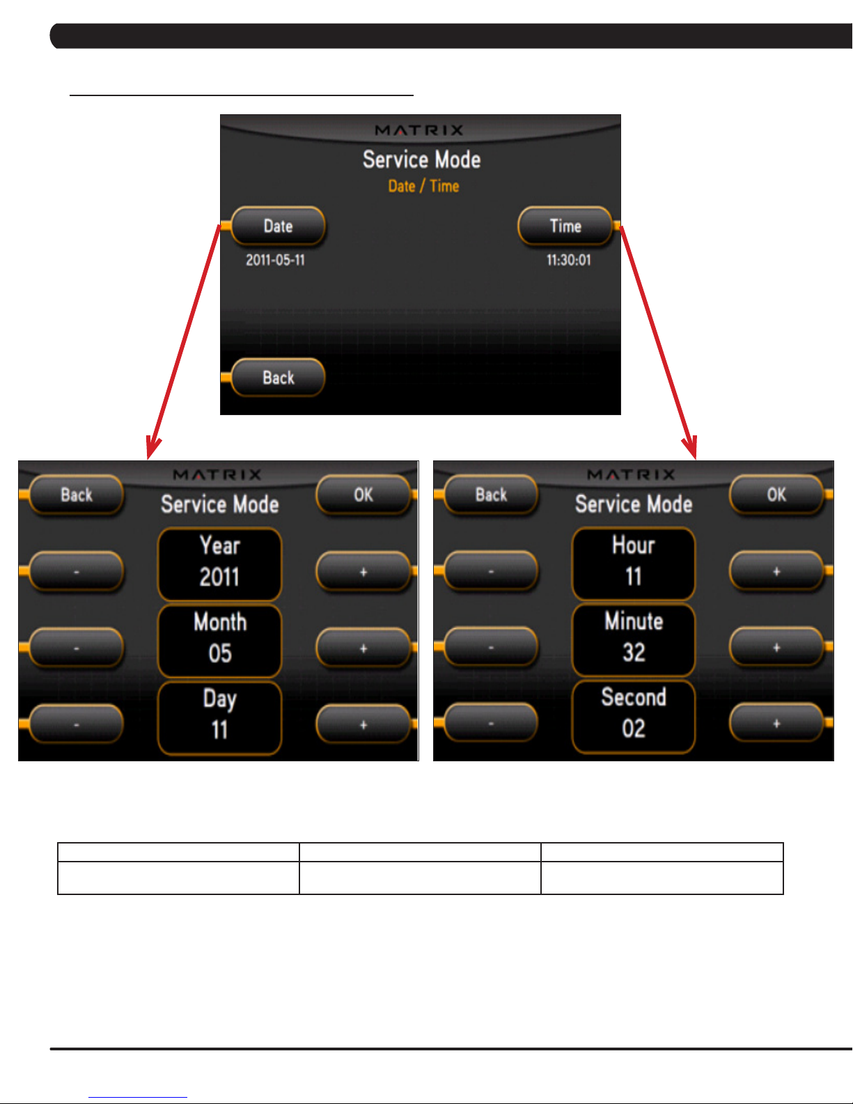
7.4 SERVICE MODE - DATE & TIME TAB
CHAPTER 7: SERVICE MODE
SERVICE MODE FUNCTION & DEFAULTS DESCRIPTIONS
Time Date & Time This option sets the current date and time on
22
the machine.
Page 26
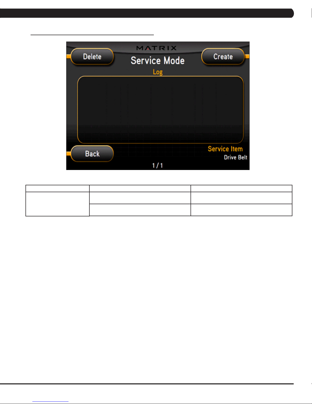
7.5 SERVICE MODE - LOG TAB
CHAPTER 7: SERVICE MODE
Log
SERVICE MODE
FUNCTION & DEFAULTS DESCRIPTIONS
Delete This option deletes key components replacement
history.
Create This option creates key components replacement
history.
23
Page 27
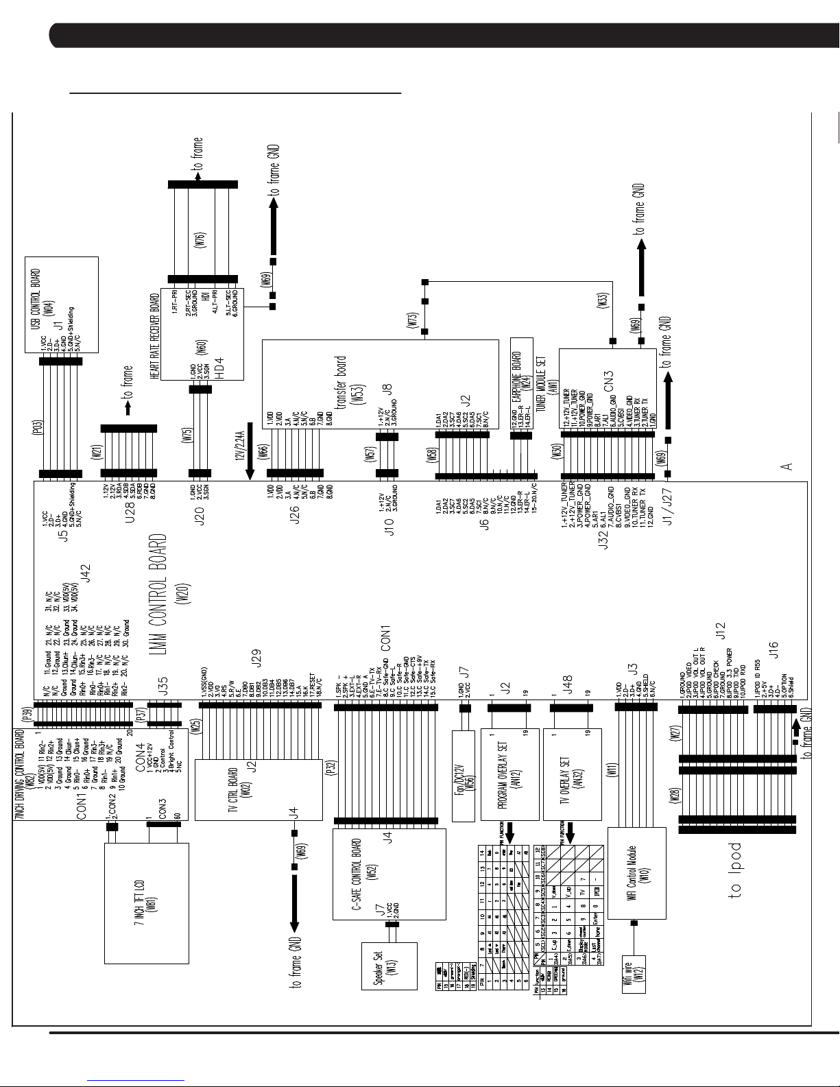
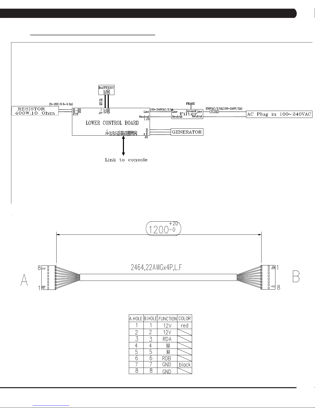
8.1 ELECTRICAL DIAGRAMS
CHAPTER 8: TROUBLESHOOTING
24
Page 28
CHAPTER 8: TROUBLESHOOTING
8.1 ELECTRICAL DIAGRAMS - CONTINUED
P21 - DIGITAL COMMUNICATION WIRE
25
Page 29

CHAPTER 8: TROUBLESHOOTING
8.1 ELECTRICAL DIAGRAMS - CONTINUED
G14 - HAND PULSE CONNECTING WIRE
26
Page 30

CHAPTER 8: TROUBLESHOOTING
8.2 ERROR CODES ON THE CONSOLE
CODE CLASS DESCRIPTION SOLUTION
0x02AB C Machine type error. Set the correct machine type in
0x02B4 C Resistance type error. Set the correct machine type in
0x0201 A Low voltage on the battery
(voltage under 11.2V).
0x0247 B LCB failed (memory write error /
feedback ADC error).
0x0248 B Battery failure or disconnection
(Voltage under 8V or over 15V).
0x0441 B When the UCB implements
a command, the LCB is not
receiving this command.
0x04A0 C Digital Communication Failure.
LCB has no return message for
the UCB for 3 seconds.
0x04B0 C UCB No Response. Check the console cable
Engineering Mode.
Engineering Mode.
Charge by running or by plugging
in the AC adapter.
Replace the LCB.
Check the wire connections at
the battery. Replace the battery.
Check the machine type in
Engineering Mode. Check the
connections at the UCB and LCB.
Check the console cable
connections at the UCB and
LCB. Replace the UCB or LCB
as needed.
connections at the UCB and
LCB. Replace the UCB or LCB
as needed.
CLASS C ERRORS WILL DISPLAY ON THE CONSOLE.
CLASS A OR B ERRORS WILL ONLY DISPLAY IN SERVICE MODE 5.
27
Page 31

CHAPTER 8: TROUBLESHOOTING
8.3 LCB LED INDICATORS
LED CHECKPOINT POSSIBLE ISSUE SOLUTION
LEDs 2, 3, 4, 6, & 7 should be ON. If they are OFF, the LCB is damaged. Replace the LCB.
If LED 1 is OFF. No AC power cord plugged in. Normal for a self powered unit. If this LED is not lit
If LED 5 is OFF. Generator has no RPM output. Normal for a powered unit. if the unit is self powered
If LED 8 is OFF. Bad communication between the UCB and LCB. Check the connection of the console cable, replace
If LED 9 is OFF. LCB is not providing 12V to the UCB. Replace the LCB.
when the unit is plugged in, replace the power cord
or power components.
and the LED is still OFF, replace the generator.
if needed.
SOLUTION IF LEDS ARE NORMAL:
1) If the LEDs are lit normally, replace the UCB and console cable.
2) if the issue is still present after the UCB and console cable are replaced, replace the LCB.
28
Page 32
CHAPTER 8: TROUBLESHOOTING
8.4 TROUBLESHOOTING - DISPLAY ISSUES
NO DISPLAY ON THE CONSOLE OR THE DISPLAY IS DIM WHEN RUNNING
POSSIBLE CAUSES:
1) The switch on the console is in the wrong position.
2) The console cable is damaged or unplugged.
3) The UCB, LCB, or console cable is damaged.
SOLUTION:
1) Check to see if the LEDs are lit on the LCB (see Section 8.3). Troubleshoot using the LED indicators.
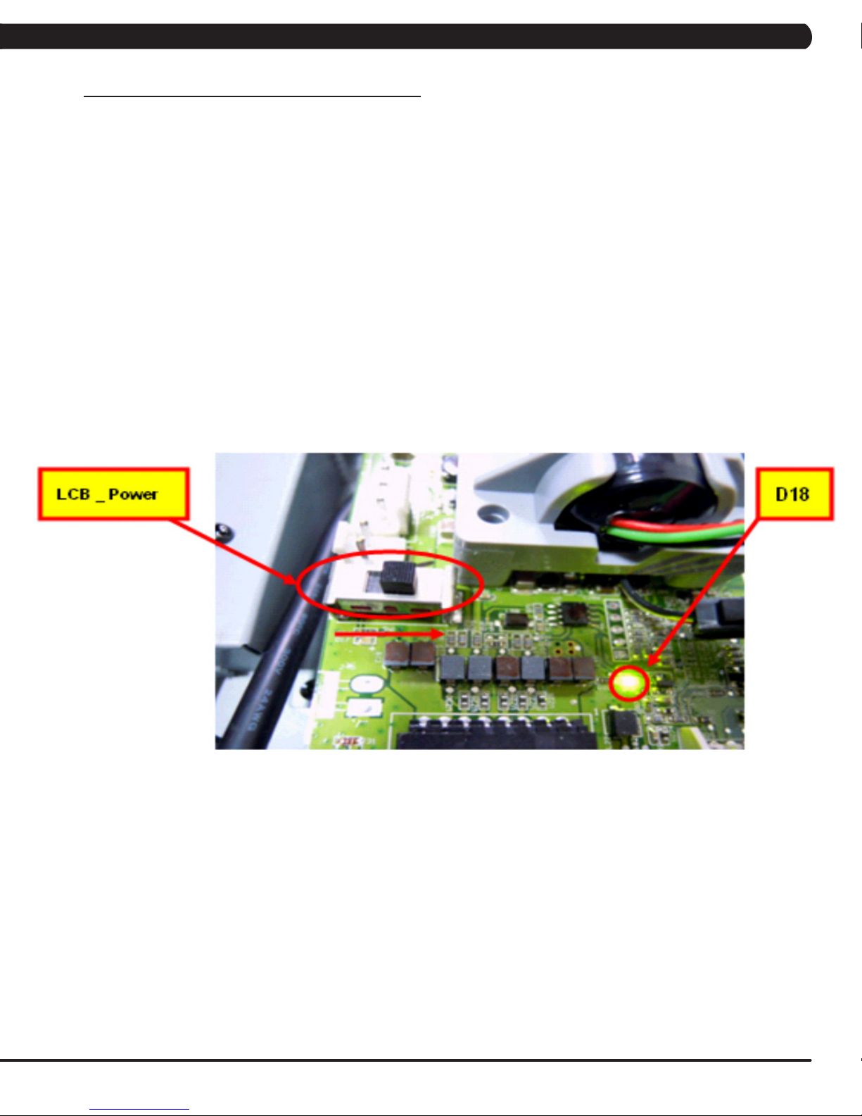
2) Check to see if LED D18 is lit on the UCB.
a. If LED D18 is lit, check the switch on the back of the UCB. It should be pointed towards the right side - LCB_Power (Figure A).
b. If LED D18 is lit, and the switch is in the correct position, but there is still no power, replace the console.
3) If LED D18 is not lit:
a. Check the console cable connection at the UCB and LCB.
b. Replace the console cable and LCB as needed.
FIGURE A
29
Page 33
CHAPTER 8: TROUBLESHOOTING
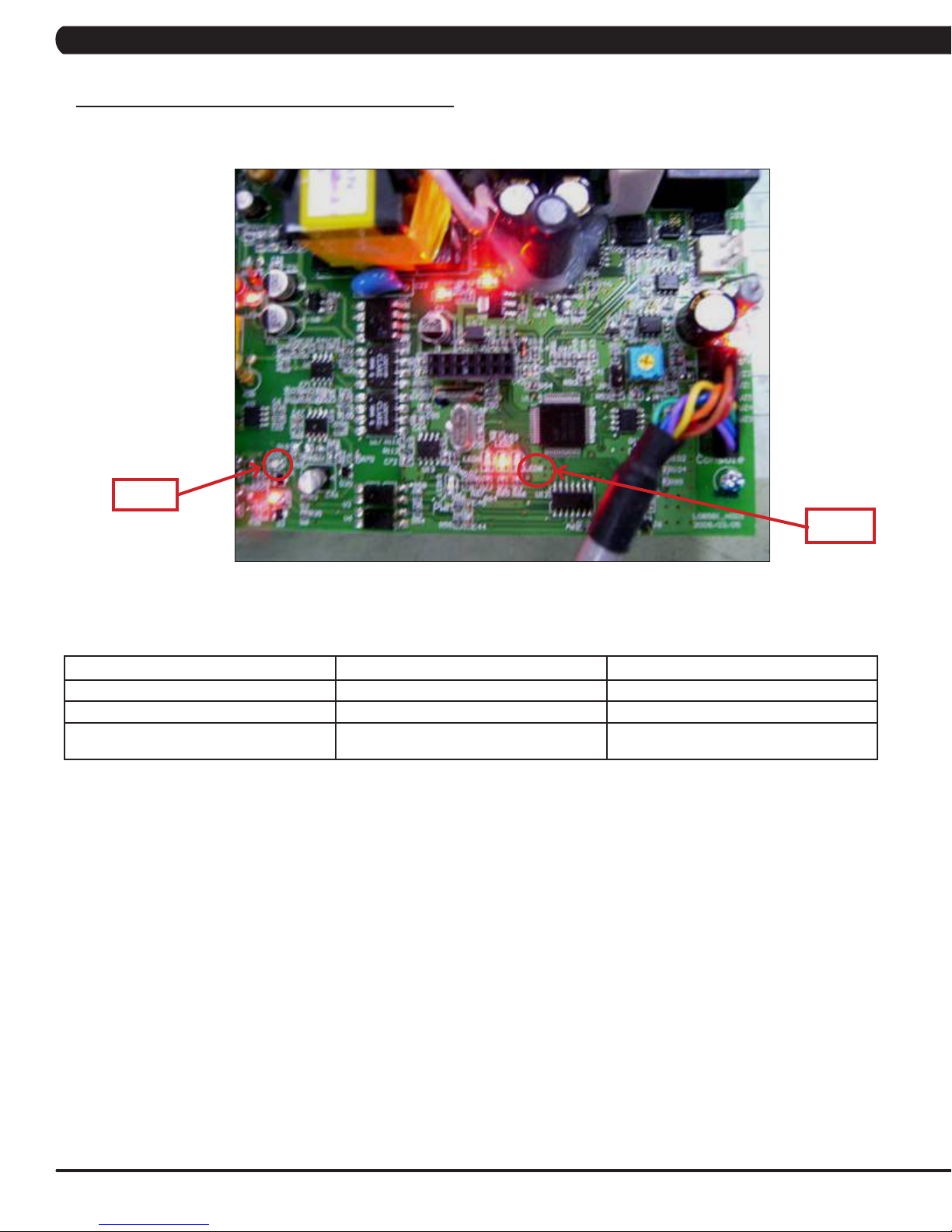
8.5 TROUBLESHOOTING - ERROR 0x04A0
ERROR 0x04A0 (DIGITAL COMMUNICATION FAILURE)
LED 1
LED 8
SYMPTOM: Error code 0x04A0 is displayed on the console.
CHECK POINT POSSIBLE ISSUE SOLUTION
LEDs 2, 3, 4, 6, and 7 should be ON. If they are OFF, the LCB is damaged. Replace the LCB.
If LED1 is OFF. No AC power cord plugged in. Normal for an unpowered unit.
If LED 8 is OFF. Bad communication between UCB and LCB. Reconnect the console cable at the LCB and
UCB and check for kinks.
SOLUTION IF LEDS ARE NORMAL:
1) If the LEDs are lit normally, replace the UCB and console cable.
2) if the issue is still present after the UCB and console cable are replaced, replace the LCB.
30
Page 34

CHAPTER 8: TROUBLESHOOTING
8.6 TROUBLESHOOTING - RESISTANCE ISSUES
HIGH OR NO RESISTANCE
POSSIBLE CAUSES:
1) The console cable is damaged or not properly plugged in.
2) The UCB is damaged.
3) The Generator is damaged.
4) The LCB is damaged.
SOLUTION:
1) Check the console cable connections at the UCB and LCB.
2) Check if the generator is outputting variable power:
a. Insert the probes from a multi-meter into the 1 & 2, 2 & 3, and 1 & 3 wires on the generator wire harness connector (Figure A).
b. When pedaling, the output voltage from the generator should vary depending on the RPM. The generator should output approximately
120 VAC at 94 RPM.
3) If the generator does not have variable power, replace the generator.
4) If the generator does have variable power, replace the LCB.
FIGURE A
31
Page 35

CHAPTER 8: TROUBLESHOOTING
8.7 TROUBLESHOOTING - PEDALS SLIPPING
PEDALS SLIPPING
POSSIBLE CAUSES:
1) The belt tension is not enough.
SOLUTION:
1) Remove the covers and check the drive belt tension.
a. The drive belt should be tightened to 180 lbf for a new belt and 150 lbf for a used belt.
8.8 TROUBLESHOOTING - NOISE ISSUES
KNOCKING OR CREAKING NOISE
NOTE:Whenanoiseisassociatedwithasinglelocationofarotation,itiscommonlyrelatedtoanexternalcomponent.Internal
componentsrotateatanacceleratedratiototheexternalcomponents.
POSSIBLE CAUSES:
1) The pedal is loose on the pedal arm.
2) The axle is worn out.
3) The belt tension is not enough, or the belts are too dirty.
4) The link arm connection to the dual action handlebar is loose.
SOLUTION:
1) Retighten the pedal on the pedal arm.
2) Replace the axle as needed.
3) Remove the covers and check the drive belt tension.
a. The drive belt should be tightened to 180 lbf for a new belt and 150 lbf for a used belt.
b. Clean the belts. If they are worn or will not clean, replace the belts.
4) Tighten the hardware where the link arm meets the dual action handlebar.
32
Page 36

CHAPTER 8: TROUBLESHOOTING
8.9 TROUBLESHOOTING - HEART RATE ISSUES
HEART RATE FUNCTION DOES NOT WORK OR IS READING INCORRECTLY
POSSIBLE CAUSES:
1) The HR grips are not hooked up correctly.
2) The HR grip wiring is damaged.
3) The console or HR board is not properly grounded.
4) The console, HR board, or wiring between are bad.
SOLUTION:
1) Perform a DC Voltage test on the HR grips.
a. With one prong of a multi meter on each of the plates on one side of the HR grip set (Figure A), a voltage reading of between .5 and 2.0
should be seen. If the reading is correct, the issue is not with the HR grips or grip wiring.
b. If the reading is not correct, remove the screws holding the halves of the HR grip together and check the connection of the wiring to the
grips (Figure B).
2) Remove the console from the unit and verify continuity of the HR grip wiring. With a multi meter set for ohms, place one prong on the HR grip
wiring coming up the console mast (Figure C), and the other on the appropriate plate (match red with red and white with white).
a. An ohm reading of less than 1 should be received. If it is higher, replace the HR grip wiring.
3) Perform a continuity check on the console (See Service Bulletin - Continuity Test on Matrix Elliptical Trainers).
a. Once the console continuity is confirmed, perform a continuity check on the HR board ground wire. With a multi meter set for ohms, place
one prong on the HR board ground wire (Figure D), and the other on the console ground wire. An ohm reading of less than 1 should be received.
If it is higher, replace the HR board.
4) If all the troubleshooting listed above has been performed, and the unit still has HR issues, replace the HR board.
a. If the HR board does not resolve the issue, replace the console.
FIGURE A
FIGURE B
FIGURE C
FIGURE D
33
Page 37

CHAPTER 8: TROUBLESHOOTING
8.10 TROUBLESHOOTING - NO POWER TO THE CONSOLE
NO POWER TO THE CONSOLE
POSSIBLE CAUSES:
1) The unit is not getting power from the outlet.
2) The LCB is not getting power from the power receptacle.
3) & 4) The LCB LEDs are lit, but there is no power to the console.
SOLUTION:
1) Verify power at the outlet. If the outlet is not outputting 120V, check the fitness room power.
a. Remove the front disk and check to see if LED9 is lit on the LCB. If it is not, verify power at the outlet. If the outlet is not outputting
120V, check the fitness room power.
b. If LED9 is still not lit after verifying the fitness room power, replace the power cord.
2) Check to see if LED9 is lit on the LCB (Figure A).
a. If LED9 is not lit, check for incoming AC voltage at the LCB. Replace the power components as needed if the voltage is not present.
b. Replace the LCB if all power components are ok and there is AC voltage to the LCB.
3) Check to see if LED D18 is lit on the upper control board (Figure B).
a. If LED D18 is lit, check the switch on the IO board, it should be towards the right side (LCB_Power - Figure B).
b. If LED D18 is not lit, check the console cable for connection at the LCB and console.
4) If LED D18 is not lit after checking the console cable connections, replace the console cable.
a. If LED D18 is lit on the console, but there is still no power, replace the console.
FIGURE BFIGURE A
34
Page 38
CHAPTER 8: TROUBLESHOOTING
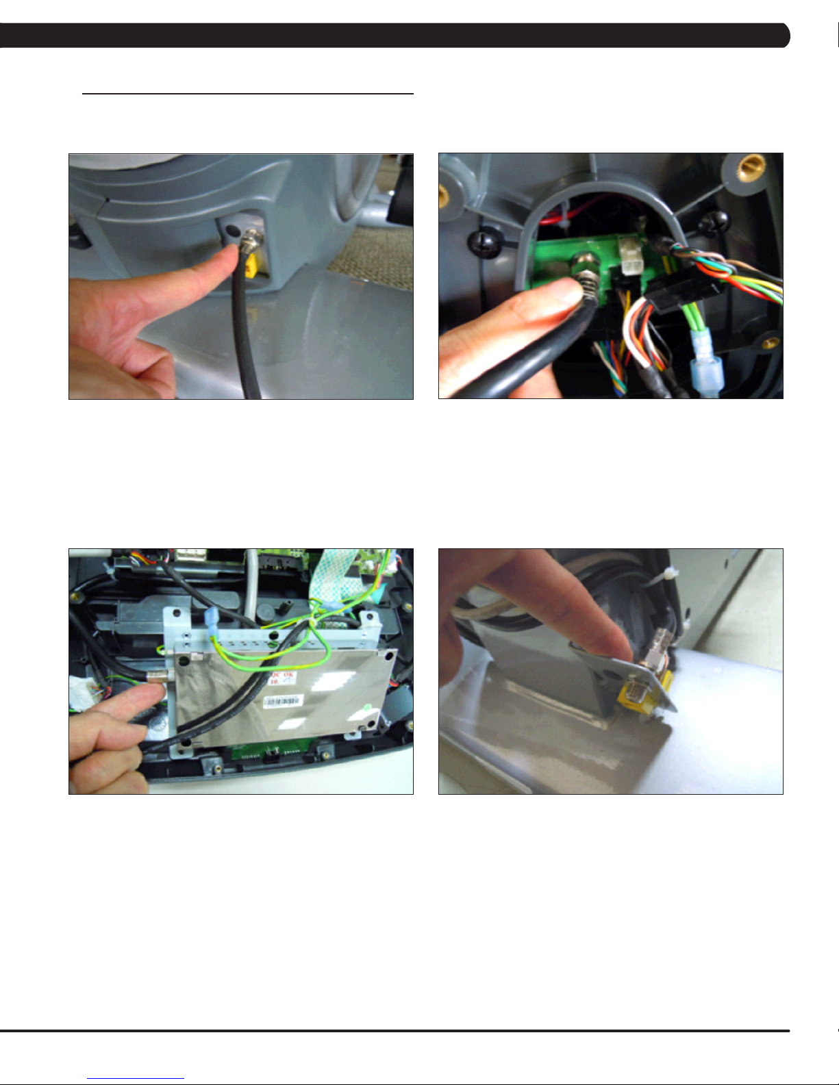
8.11 TV TROUBLESHOOTING - OVERVIEW
1) For a fuzzy or unclear picture, see the TV programming instructions in Section 10. If the TV is still fuzzy or unclear after programming:
a) Check the coax connection at the entertainment port (Figure A).
b) Remove the 5 screws holding the console to the console mast and check the coax connection at the console (Figure B).
FIGURE A
c) Use a verified good piece of coax cable (a good coax cable will have a signal strength of 10hz or greater) to plug directly into the back
of the console bypassing the entertainment port. If this resolves the issue, replace the internal coax cable.
d) If plugging the coax cable into the back of the console does not resolve the issue, remove the console back and check the console
cable connection at the tuner (Figure C).
e) Check the internal cables and fitting inside your machine at the console and below the front shroud (Figure D). Make sure you have
no kinks, cuts, or poor connectors at the end of the cable. Fittings should have a clean flush connector with no stray aluminum strands touching
the center conductor. Replace any suspect cables.
FIGURE B
FIGURE C FIGURE D
f) If no damage can be found on the cables, fittings, or connectors, and hooking the coax directly to the back of the console does not
resolve the issue, replace the TV tuner.
35
Page 39
CHAPTER 9: PART REPLACEMENT GUIDE
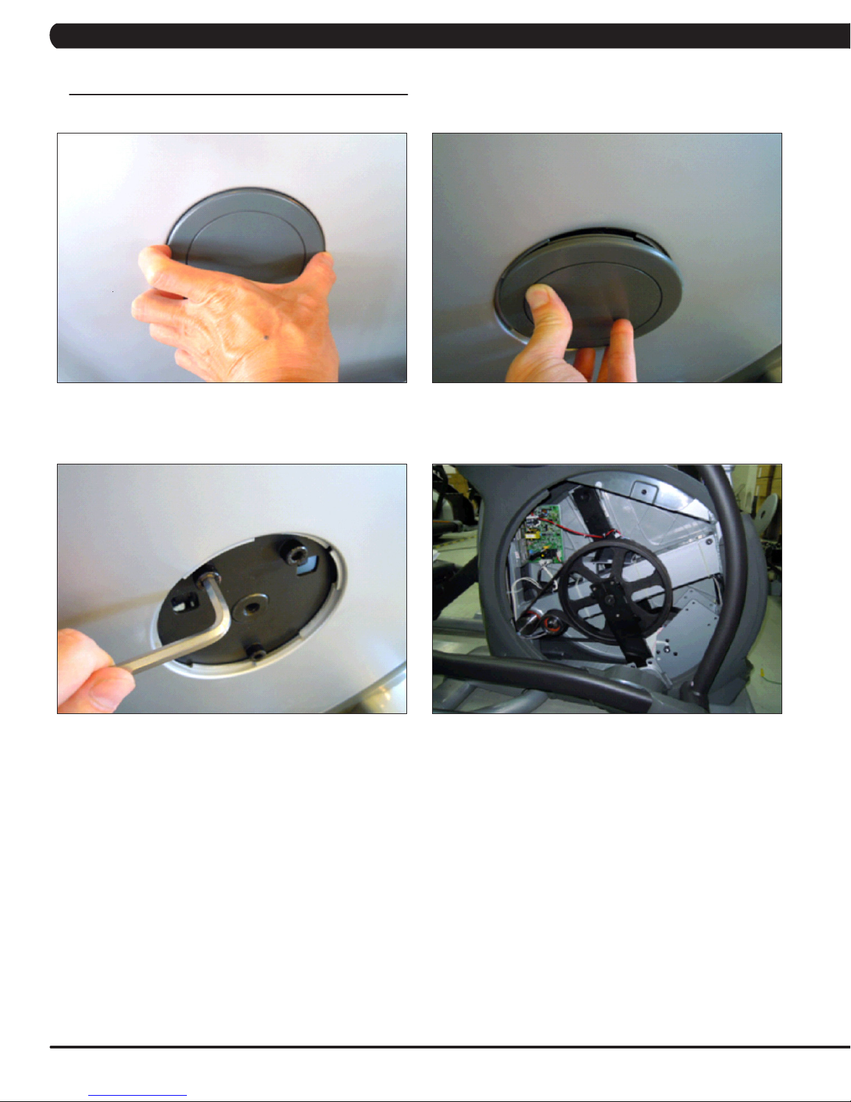
9.1 FRONT DISK REPLACEMENT
1) Remove the center cover by turning it counter clockwise (Figures A & B).
FIGURE A FIGURE B
2) Remove the 3 screws holding the disk to the axle (Figure C).
3) Remove the disk (Figure D).
FIGURE C FIGURE D
4) Reverse Steps 1-3 to install a new disk. NOTE: The 3 screws removed in Step 2 should be torqued to 25 N-m.
36
Page 40
CHAPTER 9: PART REPLACEMENT GUIDE
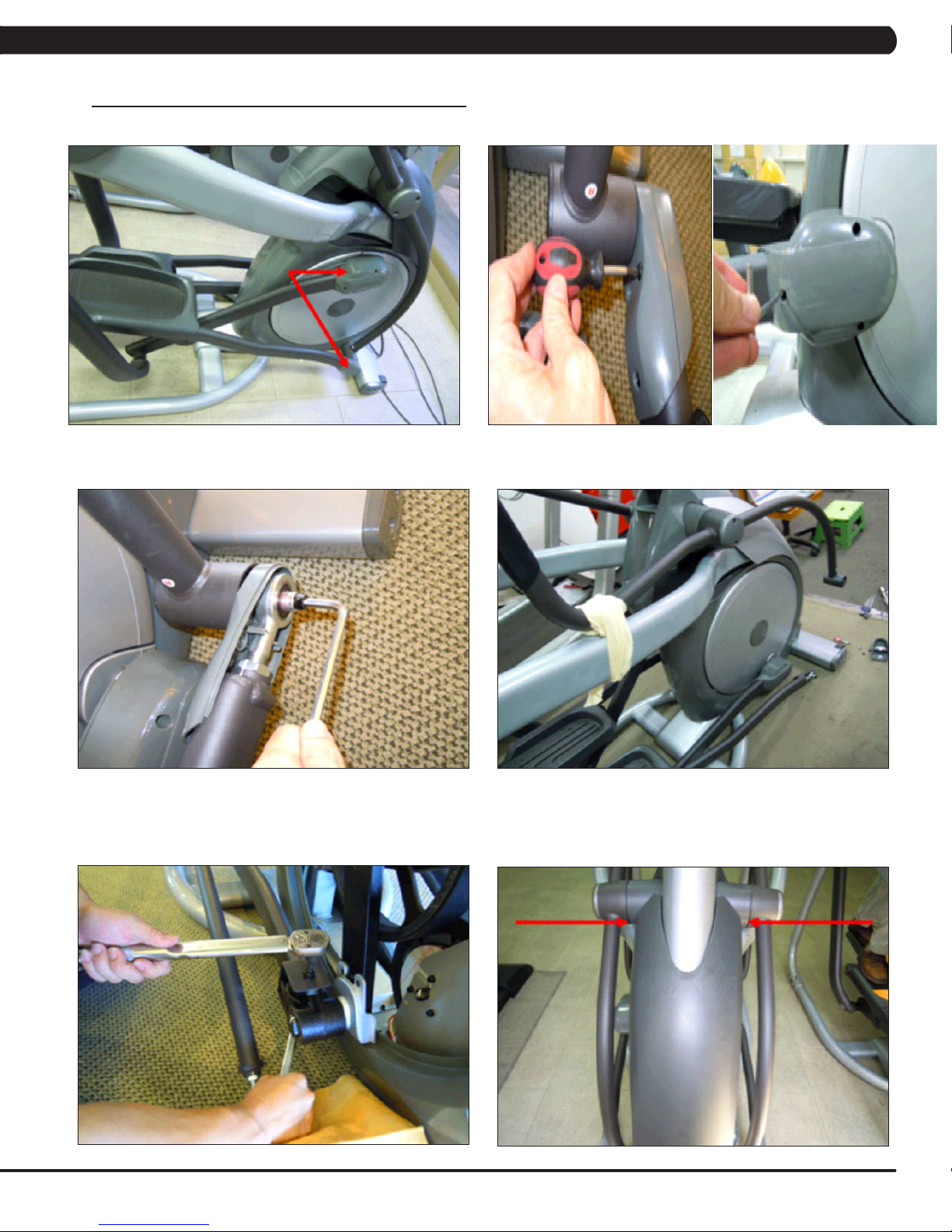
9.2 FRONT SHROUD REPLACEMENT
1) Remove the link arm and pedal arm plastic caps (Figures A & B).
FIGURE A
2) Detach the dual action handlebar from the link arm (Figure C).
3) Secure the handlebar so that it is out of the way (Figure D).
FIGURE C
4) Remove the front disks as outlined in Section 9.1.
5) Detach the pedal arm from the crank bearing assembly (Figure E).
6) Remove the 2 screws that hold the front top cover to the frame and remove the top cover (Figure F).
FIGURE B
FIGURE D
FIGURE E
FIGURE F
37
Page 41

CHAPTER 9: PART REPLACEMENT GUIDE
9.2 FRONT SHROUD REPLACEMENT - CONTINUED
7)Pullouttherubbertrayfromthecupholderplastic(gureG).
8) Remove the 2 screws to disassemble the cup holder plastic and remove it from the unit (Figure H).
FIGURE G
9) Remove the 2 screws to disassemble and remove the middle stabilizer sweat cover (Figures I & J).
FIGURE I
10) Remove the 1 screw (exposed when the cup holder is removed) holding the orange slot cover to the frame and remove it (Figure K).
11) Remove all of the cables from the front shrouds (Figure L).
FIGURE H
FIGURE J
FIGURE K
38
FIGURE L
Page 42

CHAPTER 9: PART REPLACEMENT GUIDE
9.2 FRONT SHROUD REPLACEMENT - CONTINUED
12) Remove the 9 screws to detach the front shrouds from the frame (or each other) (Figure M).
13) Turn the crank to the slotted portion of the shroud (Figure N).
FIGURE M
14) Remove the front shrouds for frame access (Figures O & P).
FIGURE O
15) Reverse Steps 1-14 to install new shrouds. NOTE: The bolt / nut removed in Step 5 should be torqued to 70 N-m.
FIGURE N
FIGURE P
39
Page 43

CHAPTER 9: PART REPLACEMENT GUIDE
9.3 LOWER CONTROL BOARD REPLACEMENT
1) Turn off the power and disconnect the cord from the machine.
2) Remove both front disks from the machine as outlined in Section 9.1.
3) Disconnect all wires from the LCB (Figure A).
FIGURE A
4) Remove the 2 screws holding the LCB to the frame (Figure B).
FIGURE B
5) Reverse Steps 1-4 to install a new LCB.
6) Test the Suspension Elliptical for function as outlined in Section 9.21.
40
Page 44
CHAPTER 9: PART REPLACEMENT GUIDE
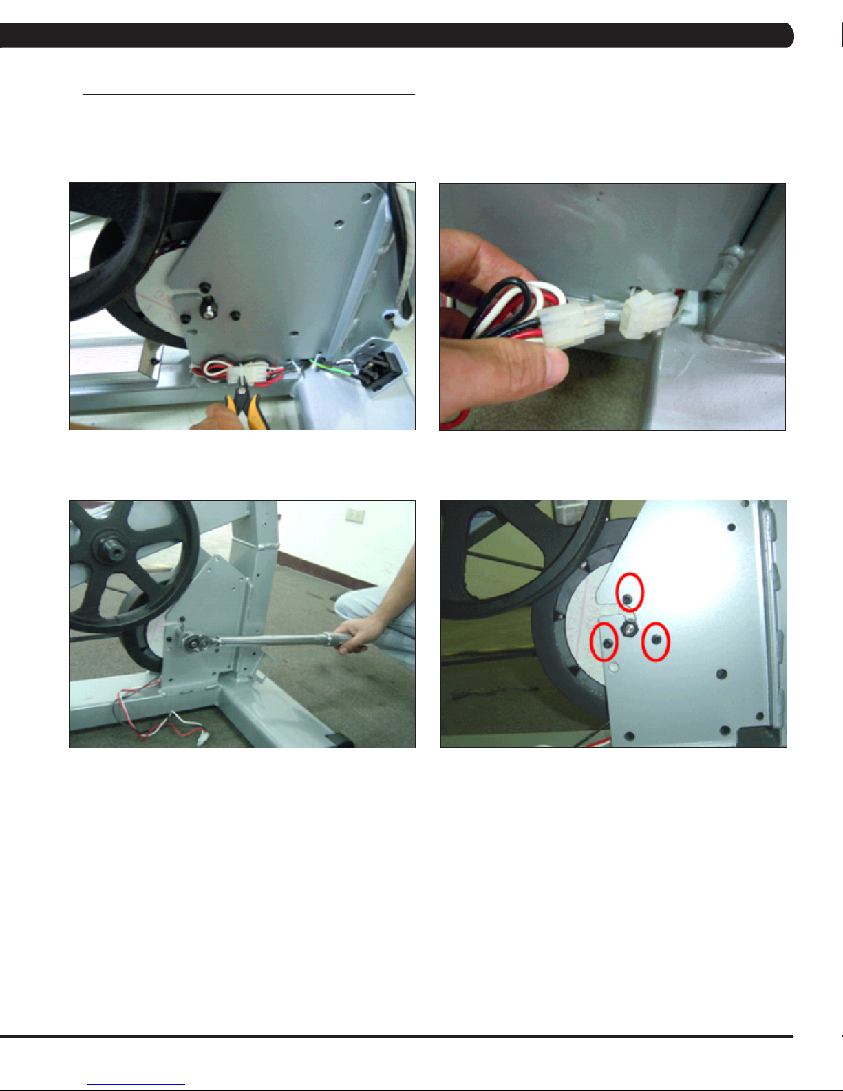
9.4 GENERATOR REPLACEMENT
1) Turn off power and disconnect the cord from the machine.
2) Remove the front disks as outlined in Section 9.1.
3) Remove the front shrouds as outlined in Section 9.2.
4) Cut the cable tie holding the cable to the frame (Figure A).
5) Unplug the power cable connector of the generator (Figure B).
FIGURE A FIGURE B
6) Loosen the nut holding the generator to the frame (Figure C).
7) Remove the three screws from the generator bracket (Figure D).
FIGURE C
FIGURE D
41
Page 45
CHAPTER 9: PART REPLACEMENT GUIDE
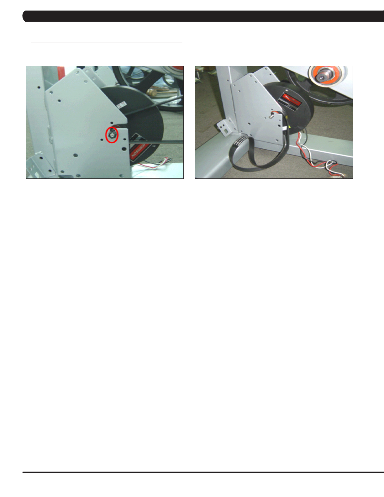
9.4 GENERATOR REPLACEMENT – CONTINUED
8) Remove the nut from the other side of the generator bracket (Figure E).
9) Loosen and remove the generator belt (Figure F).
FIGURE E FIGURE F
10) Remove the generator from the frame.
11) Reverse Steps 1-10 to install a new generator. Re-install the belts as outlined in Section 9.5. NOTE: The 3 screws removed in Step 7
should be torqued to 8 N-m and the nut from Step 8 to 40 N-m.
12) Test the Suspension Elliptical for function as outlined in Section 9.21.
42
Page 46

CHAPTER 9: PART REPLACEMENT GUIDE
9.5 GENERATOR BELT REPLACEMENT
1) Turn off the power and disconnect the cord from the machine.
2) Remove the front disks from the machine as outlined in Section 9.1.
3) Remove the front shrouds as outlined in Section 9.2.
4) Remove the generator as outlined in Section 9.4.
5)Toinstallanewbelt,rstputthebeltinstallationtoolonthepulley(FigureA).
FIGURE A
6) Put the new belt on the installation tool (Figure B).
7) Turn the pulley until the belt is installed. Rotate the pulley at least 3 full rotations to insure that the belt is centered.
FIGURE B
8) Reverse Steps 1-4 to re-assemble the unit.
9) Test the Suspension Elliptical for function as outlined in Section 9.21. .
43
Page 47

CHAPTER 9: PART REPLACEMENT GUIDE
9.6 DRIVE BELT REPLACEMENT
1) Turn off the power and disconnect the cord from the machine.
2) Remove the front disks from the machine as outlined in Section 9.1.
3) Loosen the belt tension bolt on the left side of the tension pulley and rotate the pulley counter-clockwise until there is enough slack in the
belt to remove it (Figures A & B).
FIGURE A FIGURE B
4) Install the replacement belt and reverse necessary steps to secure the assembly until the belt is tight. NOTE: Tighten the drive belt to 180
lbs. for a new belt, 150 lbs. for a used belt. The idler bolt should be torqued to 80 N-m.
5) Test the Suspension Elliptical for function as outlined in Section 9.21.
44
Page 48
CHAPTER 9: PART REPLACEMENT GUIDE
9.7 PULLEY AXLE SET REPLACEMENT
1) Turn off the power and disconnect the cord from the machine.
2) Remove both front disks from the machine as outlined in Section 9.1.
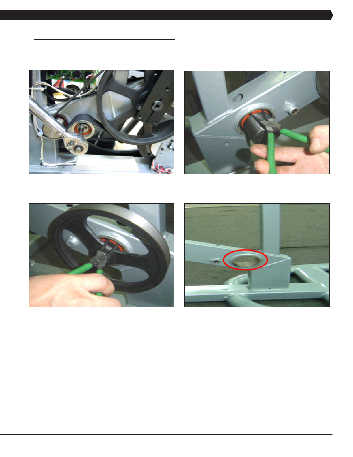
3) Loosen the belt tension bolt on the right side until there is enough slack to remove the drive belt (Figure A).
4) On the right side of the frame, remove the retaining clip that holds the pulley axle bearing into the frame (Figure B).
FIGURE A
5) On the left side of the frame, remove the retaining ring that holds the pulley axle bearing into the frame (Figure C).
6) Remove the pulley axle set assembly from the frame. Clean any debris from the hole in the frame (Figure D).
FIGURE B
FIGURE C FIGURE D
7) Reverse Steps 1-6 to install a new pulley axle set. Rotate the pulley to make sure that the motion is smooth and that there is no wobbling to
one side. Re-install the belts as outlined in Sections 9.5 and 9.6.
8) Test the Suspension Elliptical for function as outlined in Section 9.21.
45
Page 49

CHAPTER 9: PART REPLACEMENT GUIDE
9.8 DRIVE AXLE SET REPLACEMENT
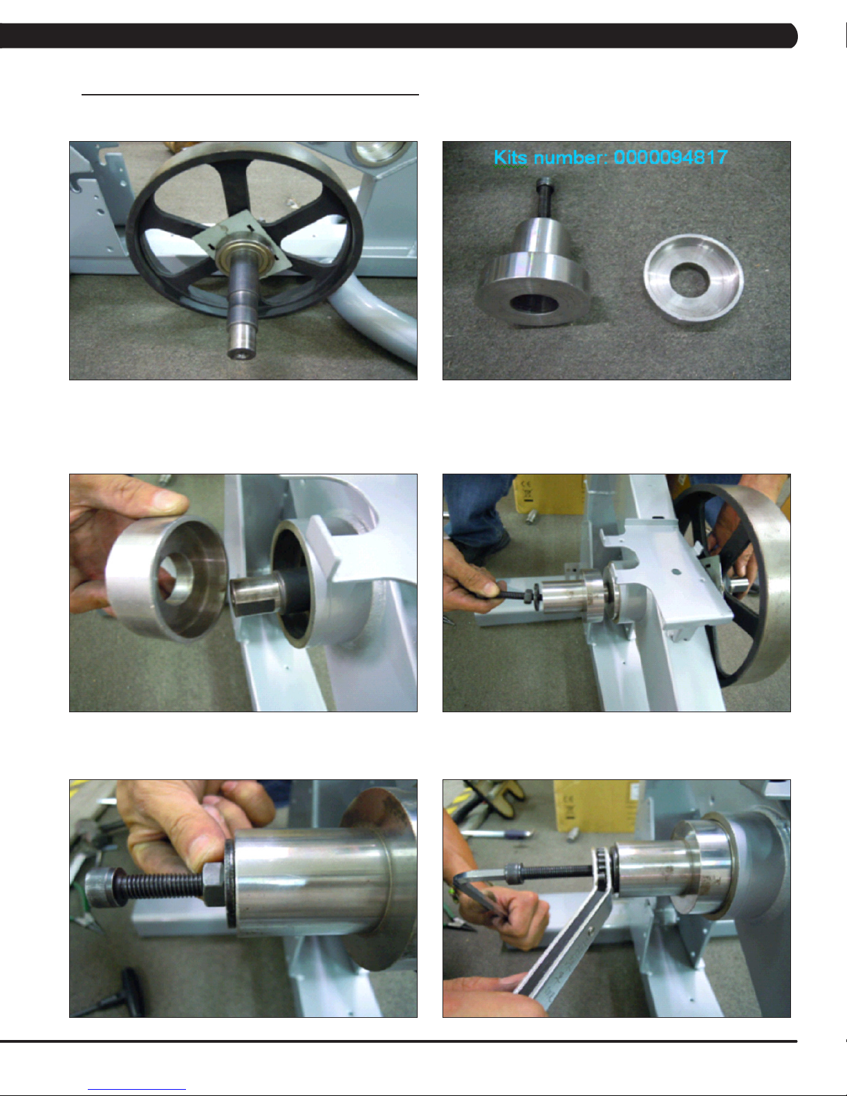
NOTE:AMatrixspecialtoolisneededtocorrectlyreplaceadriveaxle.Orderpart#0000094817fromMatrixCTSat866-693-4863ext3.
1) Turn off the power and disconnect the cord from the machine.
2) Remove the front disks from the machine as outlined in Section 9.1.
3) Remove both belts as outlined in Sections 9.5 & 9.6.
4) On the left side of the frame, remove the retainer clip that holds the drive axle bearings in the frame (Figure A).
5) Install an M10 screw into the drive axle (Figure B).
FIGURE A FIGURE B
6) Turn the screw until the head is close to the drive axle (Figure C).
7) Use a hammer to hit the screw until the drive axle assembly is loose in the frame, and remove it (Figure D).
FIGURE C
8) Install the tool into the hole in the frame (Figure E).
9) Use a rubber mallet to hit the end of the tool until the bearing can be removed from the frame (Figure F).
FIGURE D
FIGURE E FIGURE F
46
Page 50
CHAPTER 9: PART REPLACEMENT GUIDE
9.8 DRIVE AXLE SET REPLACEMENT - CONTINUED
10) The drive axle should have come with an iron plate installed (Figure G).
11) Assemble the Matrix tool as shown in Figure H.
FIGURE HFIGURE G
12) Slide the drive axle assembly into the frame from the right side. Install the bearing cap portion of the tool into the left side of the frame
(Figure I).
13) Mount the other tool from Figure H behind the bearing cap portion of the tool. Use the M10 x 65L screw with a washer and a nut to attach the
tool to the drive axle (Figure J).
FIGURE I FIGURE J
14) Turn the screw at least 4 full revolutions into the drive axle. Then turn the nut until it is close to the cup portion of the tool (Figure K).
15) Use a wrench to hold the screw, then turn the nut to pull the drive axle into the frame (Figure L).
FIGURE LFIGURE K
47
Page 51

CHAPTER 9: PART REPLACEMENT GUIDE
9.8 DRIVE AXLE SET REPLACEMENT - CONTINUED
16) Turn the nut until the iron plate is close to the frame on the right side (Figure M).
17) Remove the tools, then insert the bearing into the hole in the frame on the left side (Figure N).
FIGURE M FIGURE N
18) Again use the M10 x 65L screw with a washer and a nut to attach the tool to the drive axle (Figure O).
19) Turn the screw at least 4 full revolutions into the drive axle. Then turn the nut until it is close to the cup portion of the tool (Figure P).
20) Use a wrench to hold the screw, then turn the nut to push the bearing into the hole in the frame (Figure Q).
21) Insert the retainer clip to hold the bearing in the frame (Figure R).
48
FIGURE PFIGURE O
FIGURE RFIGURE Q
Page 52
CHAPTER 9: PART REPLACEMENT GUIDE
9.8 DRIVE AXLE SET REPLACEMENT - CONTINUED
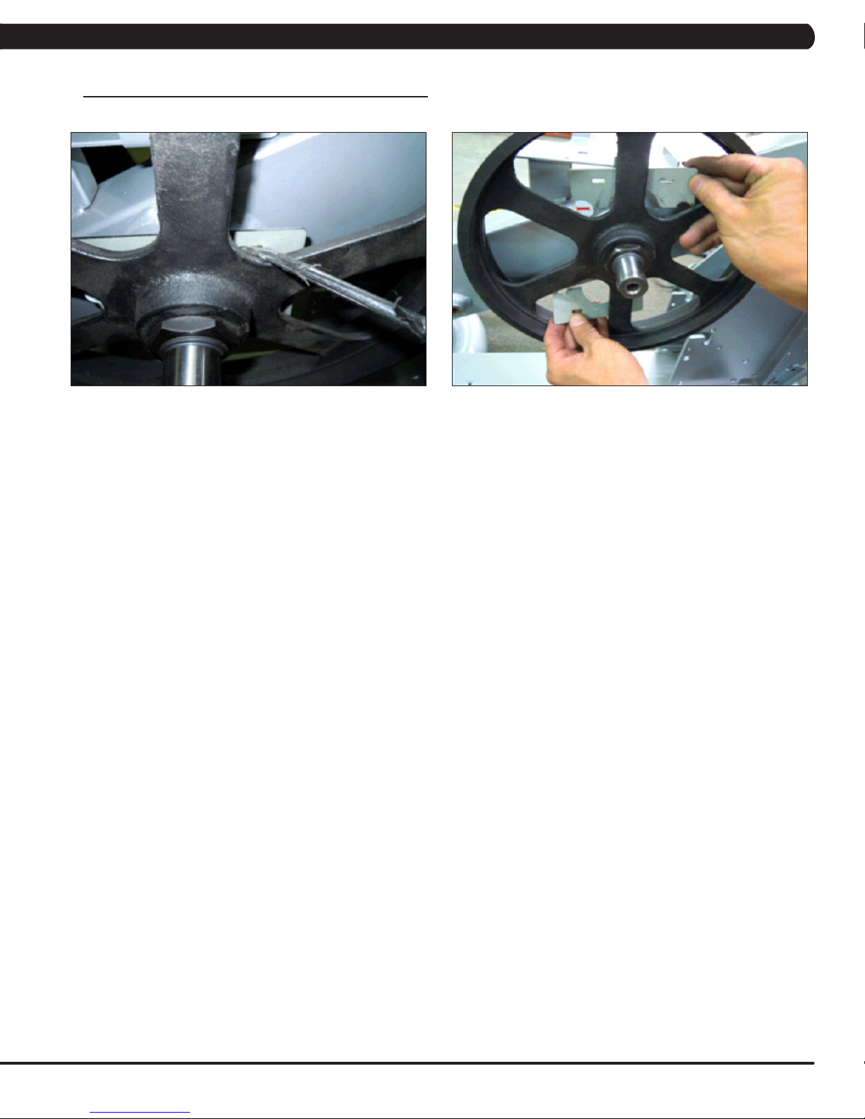
22) Use a screwdriver to remove the iron plate from the drive axle (Figures S & T).
23) Re-install the belts as outlined in Sections 9.5 and 9.6.
24) Test the Suspension Elliptical as outlined in Section 9.21.
FIGURE TFIGURE S
49
Page 53

CHAPTER 9: PART REPLACEMENT GUIDE
9.9 CRANK REPLACEMENT
1) Turn off the power and disconnect the cord from the machine.
2) Remove the front disks from the machine as outlined in Section 9.1.
3) Remove the screw from the crank (Figure A).
4) Insert an M10 screw (should be at least 40 long) into the crank hole. Then turn the screw until the crank can be separated from the axle
(Figure B).
FIGURE BFIGURE A
5) Install the replacement crank. There should be a 4mm gap between the end of the drive axle shaft and the crank (Figure C).
FIGURE C
6) Install the crank screw. NOTE: This screw should be torqued to 80 N-m.
7) Reverse Steps 1-2 to re-assemble the unit.
50
Page 54

CHAPTER 9: PART REPLACEMENT GUIDE
9.10 CONSOLE REPLACEMENT
1) Turn off the power and disconnect the cord from the machine.
2) Remove the 5 screws that hold the console to the top of the console mast (Figure A).
3) Disconnect the console cable and other wiring and remove the console (Figure B).
FIGURE A FIGURE B
4) Remove the 5 screws that hold the mounting plate to the console (Figure C).
FIGURE C
5) Attach the mounting plate to the new console.
6) Connect the wire connections to the new console.
7) Carefully push the wires into the console and mast until they are clear of the console / mast connection and attach the console to the mast
using the 5 screws removed in Step 2.
8) Test the Suspension Elliptical for function as outlined in Section 9.21.
51
Page 55
CHAPTER 9: PART REPLACEMENT GUIDE
9.11 OVERLAY & KEYPAD REPLACEMENT
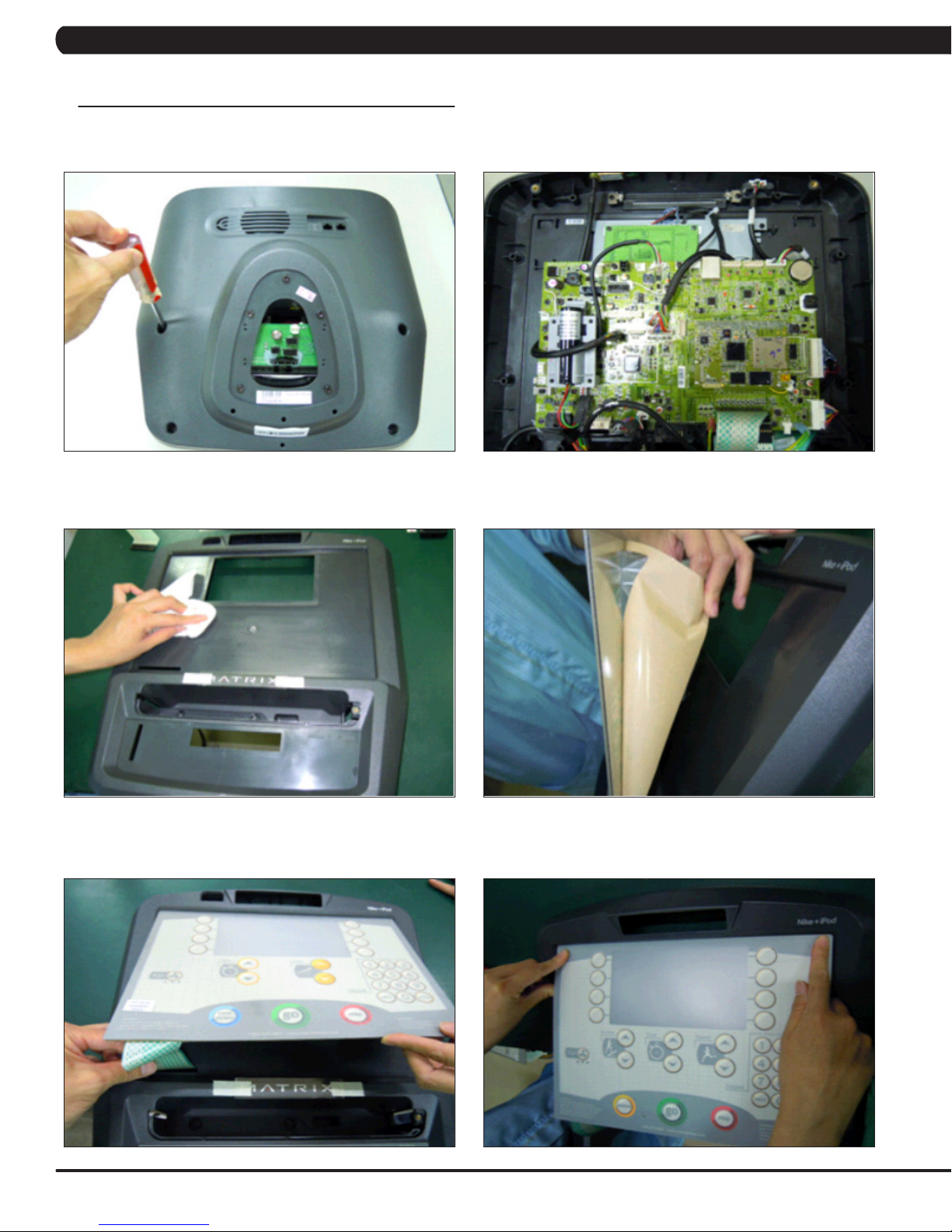
1) Remove the console as outlined in Section 9.10.
2) Remove the back cover of the console (Figure A).
3) Unplug and remove the faulty overlay (Figure B).
FIGURE A
4) Clean the console area with alcohol to remove any left over adhesive (Figure C).
5) Peel part of the protective film from the back of the overlay / keypad (Figure D).
FIGURE C FIGURE D
6) Push the overlay / keypad ribbon cable through the hole in the console and plug it in (Figure E).
7) Match the overlay / keypad to the cutout in the console (Figure F).
FIGURE B
FIGURE E FIGURE F
52
Page 56

CHAPTER 9: PART REPLACEMENT GUIDE
9.11 CONSOLE KEYPAD / OVERLAY REPLACEMENT - CONTINUED
8) Press down on the corners of the overlay / keypad to keep it in place. Then remove the protective film (Figures G & H).
FIGURE G FIGURE H
9) Once the overlay / keypad is in the correct position, press down on it to adhere it in positions (Figure I).
10) Use the same procedure to replace any additional faulty overlays / keypads. NOTE: Overlays / keypads cannot be re-used.
11) Test the Suspension Elliptical for function as outlined in Section 9.22.
FIGURE I
53
Page 57

CHAPTER 9: PART REPLACEMENT GUIDE
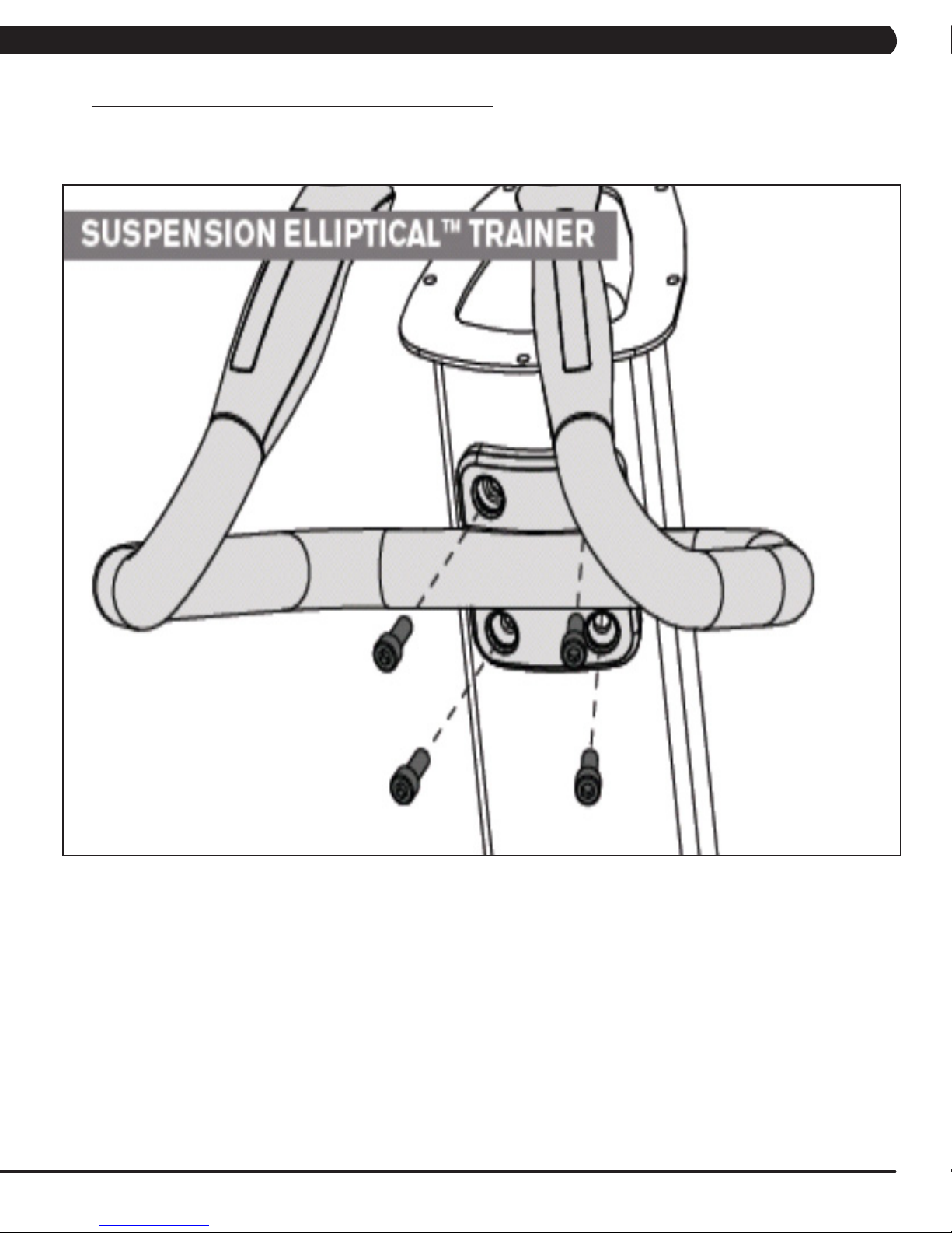
9.12 CONSOLE MAST HANDLEBAR REPLACEMENT
1) Turn off the power and disconnect the cord from the machine.
2) Remove the 4 bolts that hold the handlebar to the console mast (Figure A).
FIGURE A
3) Pull the handlebar away from the console mast to expose the HR grip wiring (Figure B).
4) Carefully remove the wires from inside the console mast until the connectors on the ends come free and disconnect (Figure C).
FIGURE B FIGURE C
5) To install a new handlebar assembly, connect the new handlebar and carefully push the heart rate wires into the console mast.
6) Attach the new handlebar assembly to the console mast using the 4 screws removed in Step 3.
7) Test the Suspension Elliptical for function as outlined in Section 9.21.
54
Page 58

CHAPTER 9: PART REPLACEMENT GUIDE
9.13 DUAL ACTION HANDLEBAR REPLACEMENT
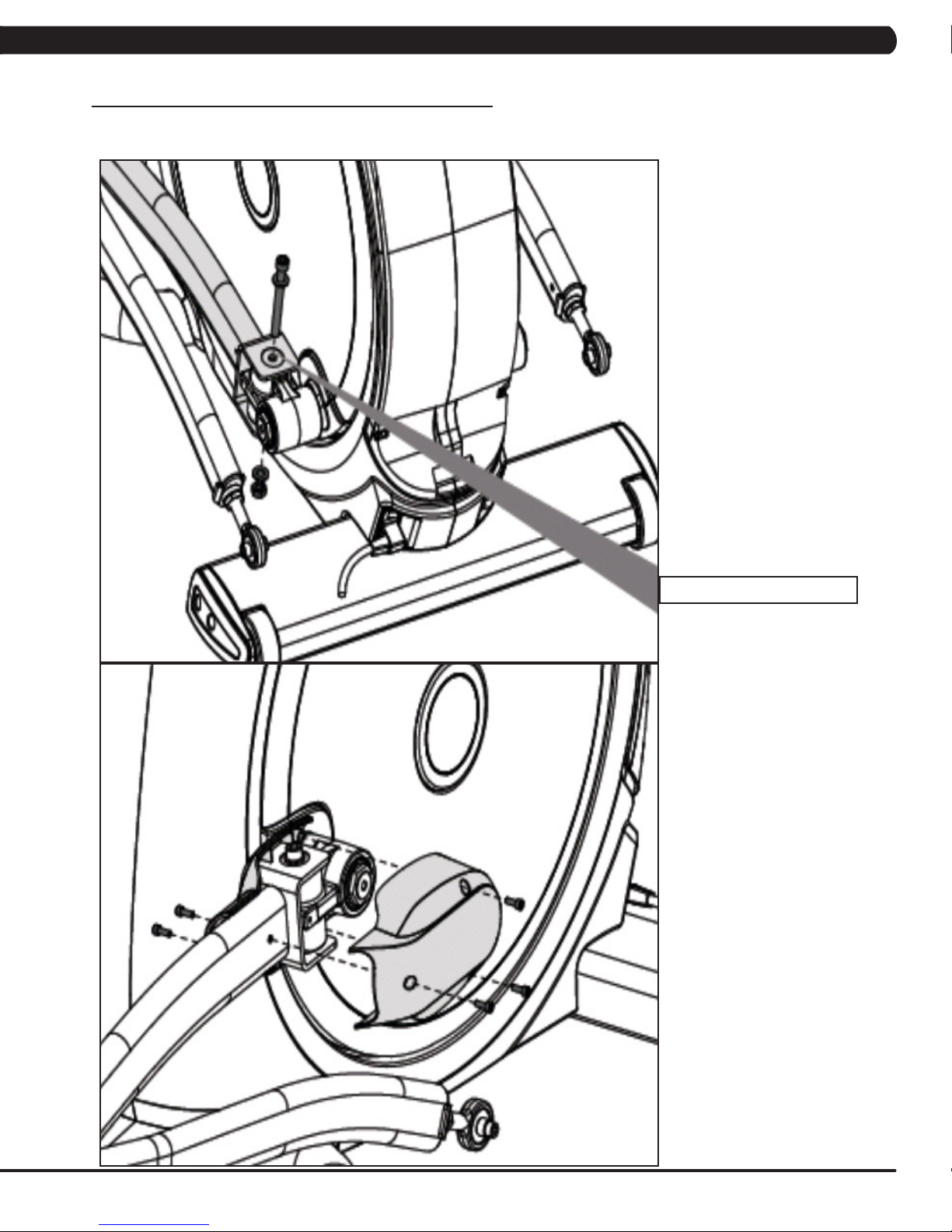
1) Remove the plastic cover where the dual action handlebar meets the link arm (Figure A).
2) Remove the bolt and bushings where the dual action handlebar and the link arm meet (Figure B).
FIGURE A FIGURE B
3) Remove the two bolts that hold on the pivot cap and remove the cap (Figure C).
4) Unplug and separate the heart rate connector exposed once the pivot cap is removed. Then remove the 4 screws that hold the dual action
handlebar to the console mast (Figure D).
FIGURE C FIGURE D
5) Reverse steps 1-4 to install a new dual action handlebar.
6) Test the Suspension Elliptical for function as outlined in Section 9.21.
55
Page 59

CHAPTER 9: PART REPLACEMENT GUIDE
9.14 FOOT PEDALS REPLACEMENT
1) Pull up on and remove the rubber portion of the pedal (Figure A).
2) Remove the 4 screws that hold the plastic pedal to the foot plate (Figure B).
FIGURE A FIGURE B
3) Remove the plastic foot pedal (Figure C).
4) Clean the foot plate to remove any rubber or debris.
5) Reverse Steps 1-4 to install a new foot pedal.
6) Test the Suspension Elliptical as outlined in Section 9.21.
FIGURE C
56
Page 60
CHAPTER 9: PART REPLACEMENT GUIDE
9.15 PEDAL ARM REPLACEMENT
1) Remove the plastic cover where the pedal arm attaches to the crank (Figure A).
2) Disconnect the pedal arm from the crank (Figure B).
FIGURE A FIGURE B
3) Remove the plastic cap from the swing arm (Figure C).
4) Remove the bolt that holds the pedal and swing arms together (Figure D).
FIGURE C FIGURE D
5) The swing arm can now be separate from the pedal arm (Figure E).
6) Remove the bolt that holds the link arm to the pedal arm and remove the pedal arm (Figure F).
FIGURE E FIGURE F
7) Reverse Steps 1-5 to install a new pedal arm. NOTE: Torque the bolt removed in Step 4 to 80 N-m and the bolt / nut removed in Step 2 to 70
N-m.
8) Test the Suspension Elliptical for function as outlined in Section 9.21.
57
Page 61

CHAPTER 9: PART REPLACEMENT GUIDE
9.16 LINK ARM REPLACEMENT
1) Remove the plastic cover where the dual action handlebar meets the link arm (Figure A).
2) Remove the bolt and bushings where the dual action handlebar meets the link arm (Figure B).
FIGURE A
3) Remove the bolt that holds the link arm to the pedal arm and remove the link arm (Figure C).
FIGURE C
4) Reverse Steps 1-3 to install a new link arm.
5) Test the Suspension Elliptical for function as outlined in Section 9.21.
FIGURE B
58
Page 62

CHAPTER 9: PART REPLACEMENT GUIDE
9.17 SWING ARM REPLACEMENT
1) Remove the bolt from the upper pivot joint on the swing arm (Figure A).
2) Remove the plastic cap from the swing arm (Figure B).
FIGURE A FIGURE B
3) Remove the bolt that holds the swing arm to the pedal arm (Figure C).
4) Take the bolt removed in Step 1 and turn it into the shaft (Figure D).
FIGURE C FIGURE D
5) Use a mallet to hit the head of the bolt until the swing arm can be separate from the pedal arm, and remove the pedal arm (Figures E & F).
FIGURE E FIGURE F
6) Reverse Steps 1-5 to install a new swing arm. NOTE: Torque the bolts removed in Steps 1 & 3 to 80 N-m when installing a new swing arm.
7) Test the Suspension Elliptical for function as outlined in Section 9.21.
59
Page 63

CHAPTER 9: PART REPLACEMENT GUIDE
9.18 VERTICAL STABILIZER ARM REPLACEMENT
1) Remove the bolt that holds the vertical stabilizer arm to the frame (Figures A & B).
FIGURE A FIGURE B
2) Remove the bolt from the upper pivot joint of the vertical stabilizer arm (Figure C).
3) Remove the vertical stabilizer arm (Figure D).
4) Reverse Steps 1-3 to install a vertical stabilizer arm. NOTE: Tighten the bolt removed in Step 2 to 80 N-m torque.
5) Test the Suspension Elliptical for function as outlined in Section 9.21.
60
FIGURE DFIGURE C
Page 64

CHAPTER 9: PART REPLACEMENT GUIDE
9.19 INCLINE ARM COVER REPLACEMENT
1) Remove the screw that holds the plastic cover on the arm (Figures A & B).
2) Remove the incline arm cover (Figure C).
FIGURE BFIGURE A
3) Reverse Steps 1-2 to install a new incline arm.
FIGURE C
61
Page 65
CHAPTER 9: PART REPLACEMENT GUIDE
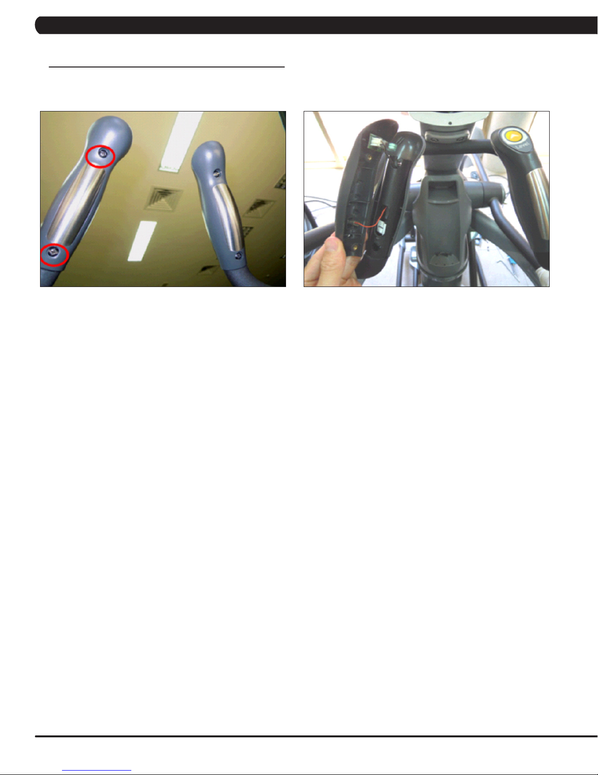
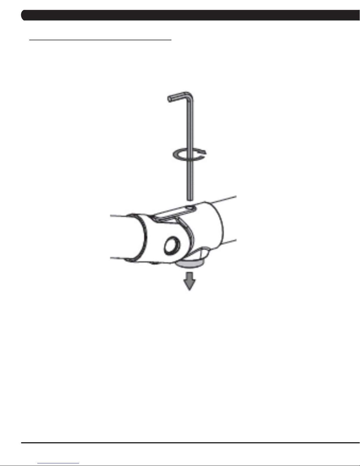
9.20 HANDLEBAR SERVICE
1) All items on the handlebar are removed using a Phillips screwdriver from the underside of the bar.
2) Once the screws are removed, lift the part carefully, then disconnect any wire connections to fully remove the part. This includes the
resistance buttons and heart rate grip plates (Figures A & B).
FIGURE BFIGURE A
62
Page 66

CHAPTER 9: PART REPLACEMENT GUIDE
9.21 TESTING THE SUSPENSION ELLIPTICAL
ONCE THE UNIT OR REPLACEMENT PART IS FULLY INSTALLED AND ASSEMBLED AND
PROPERLY PLACED ON THE FLOOR, USE THE FOLLOWING INSTRUCTIONS TO SETUP
AND TEST THE MACHINE:
1) Enter Service Mode (ENTER, 3, 0, 0, 1, ENTER) and input the serial number of the console. Also set the Machine Type and Keypad (See
Section 7.2) and verify that the Date and Time are correct (See Section 7.4). NOTE: If a setting has been changed, the unit and console
power should be reset. Cycle the power switch, and press and hold the CHANNEL UP and CHANNEL DOWN keys for 3-5 seconds to reset the
console power.
2) Enter Manager Mode (ENTER, 1, 0, 0, 1, ENTER) and turn on or off Asset Management or Virtual Active depending on whether the club has
these functions. NOTE: If a setting has been changed, the unit and console power should be reset. Cycle the power switch, and press and
hold the CHANNEL UP and CHANNEL DOWN keys for 3-5 seconds to reset the console power. Enter into and test Virtual Active.
3) Perform a channel scan on the TV (see Section 10.5).
4) Without hitting start or entering any exercise modes, stand on the machine and hold the handlebars while initiating movement to simulate
exercising. While moving listen for any odd noises or squeaks.
5) After stopping movement, press the green GO key and begin using the machine.
6) Grasp the hand grips to check for proper heart rate response.
7) Press the LEVEL UP and DOWN keys both on the hand grips and on the console to make sure resistance is fully functional.
8) If everything functions properly, stop pedaling and the unit will reset to normal operation after 30 seconds.
63
Page 67
CHAPTER 10: SUSPENSION ELLIPTICAL SPECIFICATION AND ASSEMBLY GUIDE
10.1 SUSPENSION ELLIPTICAL SPECIFICATIONS
FEATURES
Stride Length 21"
Incline Range N/A
Contact and Telemetric Heart Rate Sensors Yes
Cushioned Footpads No
Pedal Spacing 2.5"
Handlebar Design Multi-position dual action and ergo bend stationary.
Thumb Switch Controls Yes
RESISTANCE SYSTEM
Technology Generator
Power Requirements Self Powered - Powered 100V - 240V - 50 / 60 HZ AC
Minimum Watts 30 Self Powered
Minimum RPM 10 Powered / 25 Non-Powered
CONSOLE
Display Type 7" LCD
Display Feedback Time, Distance, Calories, Calories per hour, Speed, RPM, Heart Rate,
User Defined Multi Language Display Yes - English, German, French, Italian, Spanish, Dutch, Portuguese,
Resistance Levels 25
Workouts Manual, Rolling, Intervals, Fat Burn, Glute Training, Fitness Test,
CSafe, Fitlinxx Ready Yes
Netpulse Ready Yes
Fit Touch Technology No
On the Fly Program Change Yes
Integrated Vista Clear™ Digital Ready Television Yes - 7" Screen Size
Fitconnexion™ Ready Yes
Wireless Data Transmitter Yes
IPod Compatible Yes
Nike+ IPod Compatible Yes
Personal Fan Yes
USB Workout Tracking Yes - Via www.livestrong.com
Virtual Active™ Compatible Yes
METS, WATTS, Profile
Chinese, Japanese, Korean, Swedish, Finnish, Russian, Arabic
Target HR, Constant Watts
TECHNICAL DATA
Overall Dimensions (L x W x H) 81 x 34 x 79" (1780 x 742 x 1740mm)
Maximum User Weight 400 lbs / 181.4 kg
Unit Weight 399 lbs / 181.7 kg
Shipping Weight 427 lbs / 194.5 kg
64
Page 68

CHAPTER 10: SUSPENSION ELLIPTICAL SPECIFICATION AND ASSEMBLY GUIDE
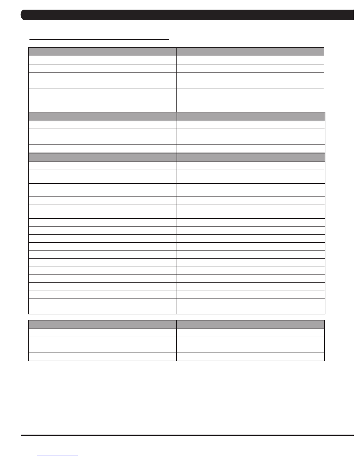
10.2 ASSEMBLY HARDWARE
QUANTITY SKETCH DESCRIPTION PACKAGE COLOR
4 SOCKET HEAD CAP SCREW
(M10 X 1.5P X 25L)
10.9 GRADE MINIMUM
RED (2 BAGS)
4 FLAT WASHER
(10.2 X 20 X 2.0T)
1 SOCKET HEAD CAP SCREW
(M10 X 1.5P X 100L)
12.9 GRADE MINIMUM
2 FLAT WASHER
(10.2 X 20 X 2.0T)
1 HEX NUT
(M10)
10.9 GRADE MINIMUM
5 SCREW
(M5 X 0.8P X 10L)
2 SCREW
(M5 X 0.8 X 12L)
4 SPRING WASHER
(8.2 X 15.4 X 2.0T)
4 SOCKET HEAD CAP SCREW
(M8 X 1.25P X 20L)
10.9 GRADE MINIMUM
1 SOCKET HEAD CAP SCREW
(M8 X 1.25P X 45L)
10.9 GRADE MINIMUM
3 SCREW
(M5 X 0.8P X 16L)
RED (2 BAGS)
GREEN
GREEN
GREEN
YELLOW
BLACK (2 BAGS)
BLACK (2 BAGS)
BLACK (2 BAGS)
BLUE (2 BAGS)
BLUE (2 BAGS)
4 SOCKET HEAD CAP SCREW
4 SPRING WASHER
12 SCREW
(M8 X 1.25P X 25L)
WHITE
WHITE
(8.2 X 13.5 X 2.0T)
PINK
(M5 X 0.8P X 16L)
65
Page 69

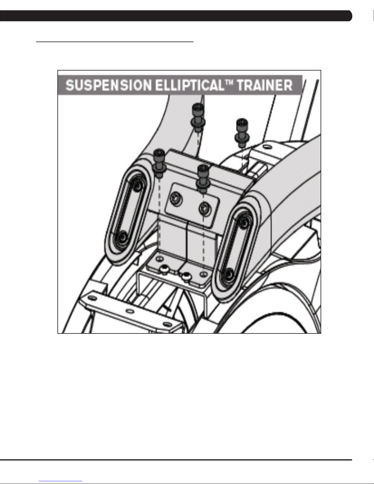
CHAPTER 10: SUSPENSION ELLIPTICAL SPECIFICATION AND ASSEMBLY GUIDE
10.3 SUSPENSION ELLIPTICAL ASSEMBLY STEPS
STEP 1
66
Page 70
CHAPTER 10: SUSPENSION ELLIPTICAL SPECIFICATION AND ASSEMBLY GUIDE
10.3 SUSPENSION ELLIPTICAL ASSEMBLY STEPS - CONTINUED
STEP 2 - RED HARDWARE BAG
67
Page 71

CHAPTER 10: SUSPENSION ELLIPTICAL SPECIFICATION AND ASSEMBLY GUIDE
10.3 SUSPENSION ELLIPTICAL ASSEMBLY STEPS - CONTINUED
STEP 3 - PINK HARDWARE BAG
68
Page 72
CHAPTER 10: SUSPENSION ELLIPTICAL SPECIFICATION AND ASSEMBLY GUIDE
10.3 SUSPENSION ELLIPTICAL ASSEMBLY STEPS - CONTINUED
STEP 4 - GREEN / YELLOW HARDWARE BAG
Torque this bolt to 80 N-m.
69
Page 73

CHAPTER 10: SUSPENSION ELLIPTICAL SPECIFICATION AND ASSEMBLY GUIDE
10.3 SUSPENSION ELLIPTICAL ASSEMBLY STEPS - CONTINUED
STEP 5 - RED HARDWARE BAG
70
Page 74

CHAPTER 10: SUSPENSION ELLIPTICAL SPECIFICATION AND ASSEMBLY GUIDE
10.3 SUSPENSION ELLIPTICAL ASSEMBLY STEPS - CONTINUED
STEP 6
71
Page 75

CHAPTER 10: SUSPENSION ELLIPTICAL SPECIFICATION AND ASSEMBLY GUIDE
10.3 SUSPENSION ELLIPTICAL ASSEMBLY STEPS - CONTINUED
STEP 7 - BLUE / BLACK HARDWARE BAG
72
Page 76
CHAPTER 10: SUSPENSION ELLIPTICAL SPECIFICATION AND ASSEMBLY GUIDE
10.3 SUSPENSION ELLIPTICAL ASSEMBLY STEPS - CONTINUED
STEP 8 - WHITE HARDWARE BAG
73
Page 77

CHAPTER 10: SUSPENSION ELLIPTICAL SPECIFICATION AND ASSEMBLY GUIDE
10.3 SUSPENSION ELLIPTICAL ASSEMBLY STEPS - CONTINUED
STEP 9 - PINK HARDWARE BAG
74
Page 78

CHAPTER 10: SUSPENSION ELLIPTICAL SPECIFICATION AND ASSEMBLY GUIDE
10.3 SUSPENSION ELLIPTICAL ASSEMBLY STEPS - CONTINUED
STEP 10 - PINK HARDWARE BAG
75
Page 79

CHAPTER 10: SUSPENSION ELLIPTICAL SPECIFICATION AND ASSEMBLY GUIDE
10.3 SUSPENSION ELLIPTICAL ASSEMBLY STEPS - CONTINUED
STEP 11 - PINK HARDWARE BAG
76
Page 80

CHAPTER 10: SUSPENSION ELLIPTICAL SPECIFICATION AND ASSEMBLY GUIDE
10.3 SUSPENSION ELLIPTICAL ASSEMBLY STEPS - CONTINUED
STEP 12 - PINK HARDWARE BAG
77
Page 81
CHAPTER 10: SUSPENSION ELLIPTICAL SPECIFICATION AND ASSEMBLY GUIDE
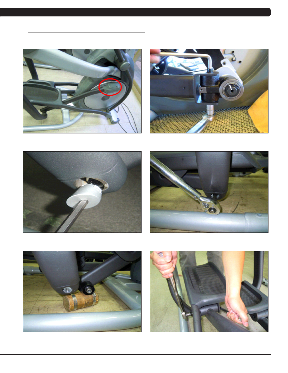
10.4 LEVELING THE SUSPENSION ELLIPTICAL
STABILIZING THE MATRIX SUSPENSION ELLIPTICAL
The Matrix Suspension Elliptical should be level for optimum use. Once you have placed your unit where you intend to use it, raise or lower
one or both of the adjustable levelers located on the bottom of the frame. Use a 6mm Allen wrench through the access hole at the rear hinge
joint on both sides (Figure A).
78
FIGURE A
Page 82

CHAPTER 10: SUSPENSION ELLIPTICAL SPECIFICATION AND ASSEMBLY GUIDE
10.5 TV PROGRAMMING INSTRUCTIONS
Once the cardio equipment has been installed, and proper power and cable wiring is provided, The Television must be programmed to the club's
channels and settings.
AutoScan - An auto scan will search for channel signals from the coax cable. It will tune in all channels that provide a signal.
1. Press ENTER, 1, 0, 0, 1, ENTER on the number keypad to enter Manager Mode.
2. Press TV on the display (Figure A).
3. Press SETUP on the display (Figure B). A TV will appear.
FIGURE BFIGURE A
4. Press the - key on the number keypad and a Menu will appear on the TV (Figure C). NOTE: Once the Menu is present on the screen, the
following buttons must be pressed quickly, or the Menu will minimize after 5 seconds of no key strokes.
5. Use the VOLUME UP or DOWN keys to move horizontally in the Menu and the CHANNEL UP and DOWN keys to move vertically.
6. Use the VOLUME UP or DOWN keys to scroll the cursor to Channel on the top right of the Menu (Figure D).
FIGURE C
7. Use the CHANNEL UP or DOWN keys to scroll down to Auto Scan, then press the VOLUME UP or DOWN keys to enter the Channel Scan
sub-menu (Figure E).
8. Use the CHANNEL UP or DOWN keys to scroll to Start To Scan, then press the VOLUME UP or DOWN keys to start the channel scan
(Figure F).
FIGURE D
FIGURE FFIGURE E
79
Page 83

CHAPTER 10: SUSPENSION ELLIPTICAL SPECIFICATION AND ASSEMBLY GUIDE
10.5 TV PROGRAMMING INSTRUCTIONS - CONTINUED
AutoScan(continued):
9. If the channels are not coming in clearly after a channel scan (or if only some channels come in), follow Steps 4-7 to enter the Auto Scan
sub-menu. Use the VOLUME UP or DOWN keys to change the Cable System to match the club's incoming frequency (Figure G), then re-run
Auto Scan.
10. If the channels are coming in clearly, press the HOME key to return to normal function (Figure H). If some channels are still not coming
in, are blurry, or are not scanning, follow the procedure below for adding / deleting a single channel. If no channels are coming in, see the
troubleshooting in Chapter 2.
FIGURE HFIGURE G
AddingorDeletingaSingleChannel-At times the Channel Scan can pick up channels that do not have a strong enough signal to
come in clearly or will fail to pick up channels that do come in clearly. Use the following procedure to manually add or delete a channel.
1. Follow Steps 1-4 in the Auto Scan instructions to access the TV Menu.
2. Use the VOLUME UP or DOWN keys to scroll to Channel on the top right of the Menu.
3. Use the CHANNEL UP or DOWN keys to scroll to Show / Hide (Figure I). Then use the VOLUME UP or DOWN keys to enter the Show /
Hide sub-menu.
4. The Show / Hide sub-menu will show a list of channels available (Figure J). Channels with a check mark are scanned in and should show
up during normal TV usage.
5. To remove or add any channel, simply scroll to the channel using the CHANNEL UP or DOWN keys, and then press ENTER to add or delete
a check mark (which adds or deletes the channel).
6. Once the desired channels are scanned in, press HOME to return to normal operation.
80
FIGURE JFIGURE I
Page 84

CHAPTER 10: SUSPENSION ELLIPTICAL SPECIFICATION AND ASSEMBLY GUIDE
10.5 TV PROGRAMMING INSTRUCTIONS - CONTINUED
ClosedCaption-Clubs will vary on whether they request the closed caption to be turned off or on. Please discuss this option with the
club manager prior to adjusting this setting.
1. Press ENTER, 1, 0, 0, 1, ENTER on the number keypad to enter Manager Mode.
2. Press TV on the display (Figure K).
3. Press SETUP on the display (Figure L). A TV will appear.
FIGURE K
4. Press the - key on the number keypad and a Menu will appear on the TV (Figure M).
5. Use the VOLUME UP or DOWN keys to scroll the cursor to Setup on the Menu (Figure N).
FIGURE L
FIGURE NFIGURE M
6. Use the CHANNEL UP or DOWN keys to scroll the cursor to Closed Caption, then press the VOLUME UP or DOWN key to enter the Closed
Caption sub-menu (Figure O).
7. Use the VOLUME UP or DOWN keys to toggle the CC Mode from ON to OFF or vice versa as needed (Figure P).
8. Press HOME to return to normal function.
FIGURE PFIGURE O
81
Page 85

CHAPTER 11: SOFTWARE UPGRADE GUIDE
11.1 SOFTWARE UPGRADE PROCEDURE
*AnACpowercordisrequiredtoupdatesoftwareinthefield.Plugintheunitpriortobeginningtheupdateprocedure.
**Allpluginsmustberemovedpriortoupdatingsoftware(forexample,noIPodcanbeconnected).Donotusetheconsolewhilean
updateisinprocess.
***IfVAisinstalledontheconsole,waituntiltheVirtualActiveicononthestandarddisplaypictureturnsredpriortoupdatingthe
software.
1) Copy five software files (SirF7xAll.cab, NK, IO_XXX, updateLMM.cofige, and Extract_CE) onto a USB drive.
2) Turn on the power to the Suspension Elliptical, wait until the standby picture has come up (Figure A).
3) Insert the USB drive into the USB Port in the console (Figure B).
FIGURE A FIGURE B
4) After a few seconds, the Suspension Elliptical will run the auto update processing (Figure C). The achieved percentage of the scheduled
process will be displayed (Figure D).
FIGURE C
FIGURE D
82
Page 86

CHAPTER 11: SOFTWARE UPGRADE GUIDE
11.1 SOFTWARE UPGRADE PROCEDURE - CONTINUED
5) When the update is complete, the display will ask you to remove the USB drive (Figure E). Once the USB is removed, the Suspension
Elliptical should reboot immediately. NOTE: If the console does not reboot normally, reset the unit power using the power switch. Also
reset the console power by pressing and holding the CHANNEL UP and DOWN keys together for 3-5 seconds. Update the software again if
problems persist.
6) Press ENTER, 1, 0, 0, 1, ENTER on the upper keypad to enter Manager Mode, then press the key next to ABOUT (Figure F).
FIGURE E
7) Press the key next to VERSIONS to verify the new software version (Figure G).
8) All of the software versions will now be displayed (Figure H). Press the HOME key to return to the standard display picture.
9) Press ENTER, 3, 0, 0, 1, ENTER to go into Service Mode. Check to see if the Machine Type is correct. If the Machine Type is not correct,
press ENTER, 3, 0, 0, 2, ENTER. This will do a software parameter reset. Then change the Machine Type. Once the Machine Type is
changed cycle unit and console power. Press the HOME key to return to the standard display picture if the Machine Type is correct.
FIGURE G
FIGURE F
FIGURE H
83
Page 87

NOTES
84
Page 88

1610 L A N D MARK D R I V E C O T TA G E G R O V E WI 5 3 5 2 7 U S A
TO LL FRE E 8 6 6 .693. 4 8 6 3
MAT R I X FITN E S S S YSTEM S C O R P.
w w w. m a tr i x f i t n e s s . c o m
REV. 01
KO
FA X 6 0 8 .839. 1 7 1 7
85
 Loading...