

Page 1

C7XI-03 CLIMB MILL
SERVICE MANUAL
Page 2

III
CHAPTER 1: SERIAL NUMBER LOCATION ........................................................... 1
CHAPTER 2: IMPORTANT SAFETY INSTRUCTIONS
2.1 Read and Save These Instructions ............................................................................. 3
2.2 Electrical Requirements ............................................................................................. 4
2.3 Locating the Unit ......................................................................................................... 5
CHAPTER 3: PREVENTATIVE MAINTENANCE
3.1 Recommended Cleaning Tips .................................................................................... 6
3.2 Care and Maintenance Instructions ........................................................................... 7
3.3 Touchscreen Care & Cleaning .................................................................................... 8
CHAPTER 4: CONSOLE OVERLAY AND WORKOUT DESCRIPTION
4.1 Console Description ................................................................................................... 9
4.2 Workout Setup Steps ................................................................................................. 10
CHAPTER 5: MANAGER MODE
5.1 Using Manager Mode ................................................................................................ 11
5.2 Manager Mode - General ........................................................................................... 12
5.3 Manager Mode - Workout .......................................................................................... 16
5.4 Manager Mode - Setup Defaults ................................................................................ 18
5.5 Manager Mode - Network .......................................................................................... 19
5.6 Manager Mode - Asset Management ......................................................................... 20
5.7 Manager Mode - Weather .......................................................................................... 20
5.8 Manager Mode - TV ................................................................................................... 21
5.9 Manager Mode - Applications .................................................................................... 22
5.10 Manager Mode - Hardware ........................................................................................ 23
5.11 Manager Mode - Service ............................................................................................ 24
CHAPTER 6: ENGINEERING MODE
6.1 Using Engineering Mode ........................................................................................... 25
6.2 Engineering Mode - General ...................................................................................... 26
6.3 Engineering Mode - Workout ..................................................................................... 30
6.4 Engineering Mode - Setup Defaults ........................................................................... 32
6.5 Engineering Mode - Network ..................................................................................... 33
6.6 Engineering Mode - Asset Management .................................................................... 35
6.7 Engineering Mode - Weather ..................................................................................... 36
6.8 Engineering Mode - TV .............................................................................................. 36
6.9 Engineering Mode - Applications ................................................................................ 38
6.10 Engineering Mode - Hardware ................................................................................... 39
6.11 Engineering Mode - Service ....................................................................................... 40
6.12 Engineering Mode - Errors ......................................................................................... 41
CHAPTER 7: SERVICE MODE
7.1 Using Service Mode. .................................................................................................. 42
7.2 Service Mode - General ............................................................................................. 43
7.3 Service Mode - Workout ............................................................................................. 47
7.4 Service Mode - Setup Defaults .................................................................................. 49
7.5 Service Mode - Update .............................................................................................. 50
7.6 Service Mode - Network ............................................................................................. 51
7.7 Service Mode - Asset Management ........................................................................... 53
7.8 Service Mode - Weather ............................................................................................ 53
7.9 Service Mode - TV...................................................................................................... 54
7.10 Service Mode - Applications ....................................................................................... 55
7.11 Service Mode - Hardware ........................................................................................... 56
7.12 Service Mode - Virtual Active ..................................................................................... 59
7.13 Service Mode - Management ..................................................................................... 59
7.14 Service Mode - Service .............................................................................................. 60
7.15 Service Mode - Errors ................................................................................................ 60
7.16 Service Mode - Netpulse ............................................................................................ 61
7.17 Matrix fitness 7xi series feature access codes ........................................................... 62
CHAPTER 8: TROUBLESHOOTING
8.1 Electrical Diagram ...................................................................................................... 63
8.2 LCB Error Indicators .................................................................................................. 70
8.3 UCB Wiring Connections ............................................................................................ 72
8.4 Error Code Troubleshooting - 01AC ........................................................................... 73
8.5 Error Code Troubleshooting - 01AF ............................................................................ 74
8.6 Error Code Troubleshooting - 02A0 ........................................................................... 75
8.7 Error Code Troubleshooting - 02BE / 02BF ................................................................ 76
8.8 Error Code Troubleshooting - 02C0 ............................................................................ 77
8.9 Error Code Troubleshooting - 02C1 ............................................................................ 78
8.10 Error Code Troubleshooting - 02C2 ............................................................................ 79
8.11 Error Code Troubleshooting - 02C3 ............................................................................ 80
8.12 Error Code Troubleshooting - 04A0 ............................................................................ 81
8.13 Error Code Troubleshooting - 04B0 ............................................................................ 82
8.14 Troubleshooting - Heart Rate Issues .......................................................................... 83
8.15 Troubleshooting - Toggle Issues ................................................................................. 86
8.16 TV Troubleshooting - Overview ................................................................................... 89
8.17 TV Troubleshooting - Picture Fuzzy or Unclear .......................................................... 90
8.18 TV Troubleshooting - TV Will Not Turn On ................................................................ 91
8.19 TV Troubleshooting - Entertainment Keypad Issues .................................................. 92
8.20 Troubleshooting - No Netpulse Network Connectivity ............................................... 93
8.21 Troubleshooting - Unable to Access the Internet ....................................................... 95
8.22 Troubleshooting - Black Screen or Initializing TV in the TV APP .............................. 97
8.23 Troubleshooting - Virtual Active Content not Found ................................................. 98
8.24 Troubleshooting - Touch Screen User and Register Buttons Unresponsive.............. 99
8.25 Troubleshooting - BOOTMGR Error ........................................................................... 100
8.26 Troubleshooting - Weather Map Won't Load ............................................................. 101
8.27 Troubleshooting - The Time is Incorrect .................................................................... 102
8.28 Troubleshooting - Unable to Boot into Matrix Home Screen . ................................... 102
CHAPTER 9: PART REPLACEMENT GUIDE
9.1 Side Cover Replacement ........................................................................................... 103
9.2 Console Replacement ................................................................................................. 105
9.3 Console Overlay / Keypad Replacement .................................................................... 106
9.4 Front Shroud Replacement ......................................................................................... 108
9.5 Lower Control Board (LCB) Replacement .................................................................. 110
9.6 Upper Handlebar Replacement .................................................................................. 111
9.7 Lower Handlebar Replacement .................................................................................. 113
9.8 Handlebar Service ....................................................................................................... 114
9.9 Stair Replacement ....................................................................................................... 115
9.10 Drive Set Replacement ............................................................................................... 117
9.11 Chain Replacement ..................................................................................................... 119
9.12 Brake Replacement ..................................................................................................... 121
9.13 Fan Replacement ........................................................................................................ 122
9.14 ECB Belt Replacement ............................................................................................... 123
9.15 Drive Belt Replacement .............................................................................................. 124
9.16 ECB Replacement ....................................................................................................... 125
9.17 Speed Sensor Replacement ....................................................................................... 127
9.18 Control Zone Replacement ......................................................................................... 128
9.19 Proximity Sensor Replacement ................................................................................... 129
9.20 IR Sensor Replacement .............................................................................................. 130
9.21 CF Card Replacement .............................................................................................. 132
9.22 Console Parts Replacement ..................................................................................... 133
9.23 Testing the Climb Mill .................................................................................................. 135
CHAPTER 10: CLIMB MILL SPECIFICATIONS AND ASSEMBLY GUIDE
10.1 Climb Mill Specifications ............................................................................................ 136
10.2 Assembly Hardware .................................................................................................... 137
10.3 Climb Mill Assembly Steps ......................................................................................... 138
10.4 Stabilizing the Climb Mill ............................................................................................. 142
10.5 TV Programming Instructions ..................................................................................... 143
10.6 Using Update Manager .............................................................................................. 153
10.7 Netpulse & AM Setting SOP ...................................................................................... 157
CHAPTER 11: SOFTWARE UPGRADE PROCEDURE
11.1
Software Upgrade Procedure from Website ............................................................... 176
11.2 Software Upgrade Procedure from USB .................................................................... 178
11.3 Software Upgrade Procedure for LCB ........................................................................ 181
TABLE OF CONTENTS TABLE OF CONTENTS
Page 3

1.1 SERIAL NUMBER LOCATION
CHAPTER 1: SERIAL NUMBER LOCATION
SERIAL NUMBER LOCATION
1
Page 4

3
2
1.1 SERIAL NUMBER LOCATION - CONTINUED
CHAPTER 1: SERIAL NUMBER LOCATION
2.1 READ AND SAVE THESE INSTRUCTIONS
CHAPTER 2: IMPORTANT SAFETY INSTRUCTIONS
console serial number location
CONSOLE SERIAL NUMBER LOCATION
This Climb Mill is intended for commercial use. To ensure your safety
and protect the equipment, read all instructions before operating the
MATRIX Climb Mill.
When using an electrical product, basic precautions should always be
followed including the following:
• Anapplianceshouldneverbeleftunattendedwhenplugged
in. Unplugtheunitfromtheoutlet whennotinuseandbefore
puttingonortakingoffanyparts.
• Thisproductmustbeusedforitsintendedpurpose
describedinthisservicemanual. Donot useother
attachmentsthatarenotrecommendbythe manufacturer.
Attachmentsmaycauseinjury.
• Topreventelectricalshock,neverdroporinsertanyobject
intoanyopening.
• Donotremovethesidecovers.Serviceshouldonlybedone
byanauthorizedservicetechnician.
• Neveroperatetheunitwiththeairopeningblocked.Keep
theairopeningclean,freeoflint andhair.
• Neveroperatetheunitifithas adamagedcordorplug,if it
isnotworkingproperly,if ithasbeendamaged,orimmersed
inwater.
• Closesupervisionisnecessary whentheunitisused byor
nearchildrenordisablepersons.
• Donotuseoutdoors.
• Donotoperatewhere aerosol(spray)productsarebeing
usedorwhenoxygenisbeingadministered.
• Donotusetheequipmentin anywayotherthandesignedor
intendedbythemanufacturer.Itisimperativethatall Matrix
FitnessSystemsequipmentisusedproperlyto avoidinjury.
• Keephandsandfeetclearofmoving partsatalltimesto
avoidinjury.
• Unsupervisedchildrenmustbekeptawayfrom thisequip
ment.
• Donotwearlooseclothingwhileon theequipment.
*AtNOtimeshouldpets orchildrenundertheageof 14be
closertotheunitthan10feet.
* AtNOtimeshouldchildrenunderthe ageof14usetheunit.
* Childrenovertheageof14or disabledpersonsshouldnot
usetheunit withoutadultsupervision.
* Neveroperatetheunitifithas adamagedcordorplug,if it
isnotworking properly,ifithasbeendroppedor damaged,or
immersedinwater.Returnthe unittoaservicecenterfor
examinationandrepair.
* Todisconnect,turnallcontrolstotheoffposition, then
removeplugfrom outlet.
* Donotremovetheconsolecoversunless instructedby
CustomerTechSupport.Service shouldonlybedonebyan
authorizedservicetechnician.
* Thisunitisnotequippedwitha freewheel.Stepspeed
shouldbe reducedinacontrolledmanner.
* Heartratemonitoringsystemsmaybeinaccurate.
* Overexercisingmayresultinseriousinjury ordeath.
* Ifyoufeelfaint,stopexercisingimmediately.
CAUTION! Ifyouexperiencechestpains, nausea,dizziness,or
shortnessofbreath,stopexercisingimmediatelyand consult
yourphysicianbeforecontinuing.
CAUTION! Anychangesormodificationstothis equipment
couldvoidtheproductwarranty.
Page 5
5
4
2.2 ELECTRICAL REQUIREMENTS
CHAPTER 2: IMPORTANT SAFETY INSTRUCTIONS
2.3 LOCATING THE UNIT
CHAPTER 2: IMPORTANT SAFETY INSTRUCTIONS
DEDICATED CIRCUIT AND ELECTRICAL INFO
A “Dedicated Circuit” means that each outlet you plug into should not have anything else running on that same circuit. The easiest way to verify
this is to locate the main circuit breaker box, and turn off the breaker(s) one at a time. Once a breaker has been turned off, the only thing that
should not have power to it are the units in question. No lamps, vending machines, fans, sound systems, or any other item should lose power
when you perform this test.
Non-looped (isolated) neutral/grounding means that each circuit must have an individual neutral/ground connection coming from it, and
terminating at an approved earth ground. You cannot “jumper” a single neutral/ground from one circuit to the next.
ELECTRICAL REQUIREMENTS
For your safety and to ensure good unit performance, the ground on this circuit must be non-looped (isolated). Please refer to NEC article 21021 and 210-23. Any alterations to the standard power cord provided could void all warranties of this product.
The 3x, 5x and 7xe
Climbmills are designed to be self-powered and do not require an external power supply source to operate. Without an
external power supply, the console’s start-up time may be delayed. Add-on TV’s and other console accessories will increase the time needed
for start-up. An external power supply will ensure power is provided to the console at all times and is recommended when add-on accessories
are used.
For units with an integrated TV (like the 7xe and 7xi), the TV power requirements are included in the unit. An RG6 coaxial cable with ‘F Type’
compression fittings on each end will need to be connected to the cardio unit and the video source. Additional power requirements are not
needed for the add-on digital TV (3x and 5x). For units with an add-on PCTV (3x and 5x), the TV power requirements are separate.
NOTE: ALL UNITS WITH VIRTUAL ACTIVE™ MUST BE POWERED!
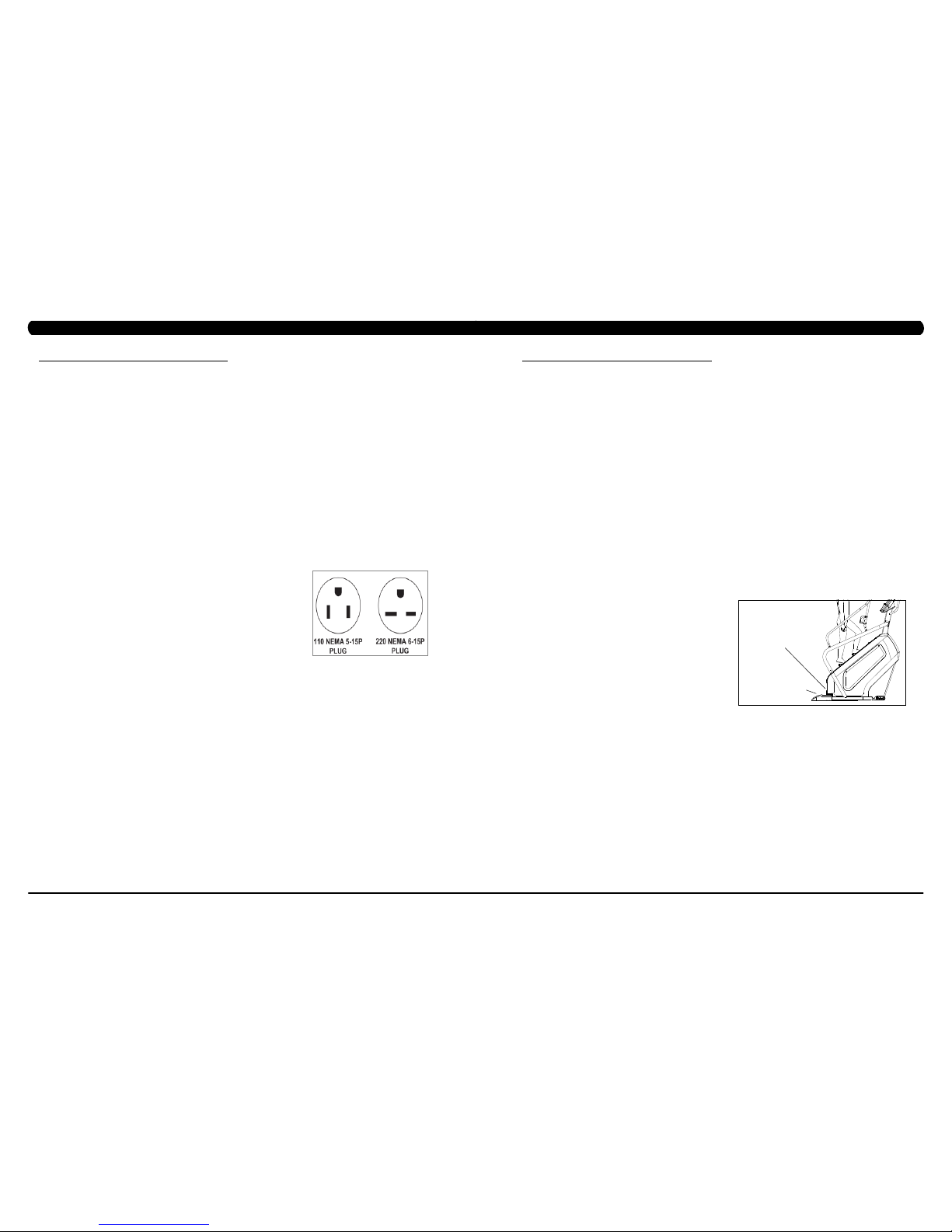
110 V UNITS
All Matrix 3x, 5x, 7xe and 7xi 110 V Climbmills require the use of a 100-125 V, 60 Hz and a 15 A
“Dedicated Circuit”, with a non-looped (isolated) neutral/ground for power. This outlet should be a
NEMA 5-15R and have the same configuration as the plug. No adapter should be used with this
product. These bikes can be daisy-chained together with up to 4 units per 15 A dedicated circuit.
Matrix daisy-chain cord adapters are sold separately.
220 V UNITS
All Matrix 3x, 5x, 7xe and 7xi 220 V Climbmills require the use of a 216-250 V, 50 Hz and a 15 A
“Dedicated Circuit”, with a non-looped (isolated) neutral/ground for power. This outlet should be a
NEMA 6-15R and have the same configuration as the plug. No adapter should be used with this
product. These bikes can be daisy-chained together with up to 4 units per 15 A dedicated circuit.
Matrix daisy-chain cord adapters are sold separately.
North American power cord plugs shown.
Depending on your country, the plug type may vary.
GROUNDING INSTRUCTIONS
The unit must be grounded. If it should malfunction or breakdown, grounding provides a path of least resistance for electric current to reduce
the risk of electric shock. The unit is equipped with a cord having an equipment-grounding conductor and a grounding plug. The plug must be
plugged into an appropriate outlet that is properly installed and grounded in accordance with all local codes and ordinances. If the user does
not follow these grounding instructions, the user could void the Matrix limited warranty.
ADDITIONAL ELECTRICAL INFO
In addition to the dedicated circuit requirement, the proper gauge wire must be used from the circuit breaker box, to each outlet that will have
the maximum number of units running off of it. If the distance from the circuit breaker box to each outlet, is 100 ft (30.5 m) or less, then 12
gauge wire should be used. For distances greater than 100 ft (30.5 m) from the circuit breaker box to the outlet, a 10 gauge wire should be
used.
ENERGY SAVING / LOW-POW ER MODE
All units are configured with the ability to enter into an energy saving / low-power mode when the unit has not been in use for a specified period
of time. Additional time may be required to fully reactivate this unit once it has entered the low-power mode. This energy saving feature may be
enabled or disabled from within the ‘Manager Mode’ or ‘Engineering Mode.
LOCATION OF THE UNIT
Place the unit on a level surface and away from direct sun light. The intense UV light can cause discoloration of plastics. Locate in an area
with cool temperatures and low humidity. Leave a clear zone behind the unit of at least 24". This zone must be clear of any obstruction and
allow the user a clear exit path from the unit. Do not place the unit in any area that will block the openings or vents. The unit should not be
used in a garage or covered patio.
LEVELING THE UNIT
Locate a level, stable surface to position the equipment. The equipment has levelers located below the bottom step. To access the levelers,
remove the end caps (C3X) or CONTROL ZONE (C5X, C7XE and C7XI). CAUTION: There is an electrical plug located under the CONTROL
ZONE and will need to be unplugged before the cover can be completely removed. Use an allen wrench to level the unit. Once stable, replace
parts as they were removed.
HEIGHT REQUIREMENTS
The Climb Mill adds 30" - 38" (76 - 96cm) to a user's height. For example, a 6' (183cm) tall user will be 7'8" (234.4cm - 254.4cm) off the floor.
Total height of the user on the Climb Mill should not exceed 9'10" (300 cm), which means that users taller than 6'8" (204cm) should not use this
equipment.
AUTO STOP
SENSOR
CONTROL ZONE
(C5X, C7XE, C7XI)
Page 6

7
6
3.1 RECOMMENDED CLEANING TIPS
CHAPTER 3: PREVENTATIVE MAINTENANCE
3.2 CARE AND MAINTENANCE INSTRUCTION
CHAPTER 3: PREVENTATIVE MAINTENANCE
FIGURE A FIGURE B
In order to maximize life span, and minimize down time, all Matrix Fitness Equipment requires regularly
scheduled cleaning.
YOU WILL NEED:
- Mild dish soap and water mixture in a spray bottle (10:1 water to soap ratio).
- Lint free 100% cotton cleaning cloths or Micro fiber cleaning cloths.
- Vacuum / Shop Vac with extendable hose and soft brush attachment.
- iPod corrosion blocker - Available from Matrix (part # ZMS4001374).
- Super Lube Multi Purpose Synthetic Lubricant with Syncolon® (PTFE) Aerosol - www.super-lube.com/sythetic-aerosol-spray-ezp-46.html.
- Corrosion Block (available from Matrix - part # ZMS4001374).
- LCD / LED or computer screen cleaner.
DAILY or as needed:
1. Empty the dust tray under the stairs and under the unit (Figure A). If you need to move the unit, unplug it first.
WEEKLY:
1. With a clean dry 100% lint free cloth and water / soap mixture, wipe down the entire frame including the stairs so it is free of dust, dirt, and
sweat.
2. With a clean dry 100% lint free cloth and water / soap mixture, wipe down the entire console area including the hand grips and hand rails.
MONTHLY:
1. Vacuum under and around the Climb Mill If you need to move the unit, unplug it first. Make sure to reset the casters after moving the unit
back into position to stabilize the unit.
2. Apply corrosion block to the metal part of the iPod cable.
3. Use a computer screen cleaner or LCD / LED screen cleaner on the touch screen portion of the console (see Section 3.3).
QUARTERLY:
1. Remove the side access panels and vacuum out the inside of the unit (Figure B).
2. Unplug the Climbmill and clean the AUTO STOP SENSORS (located under the bottom step) / Control Zone sensor with a cotton swab
and rubbing alcohol.
In order to maximize life span, and minimize down time, all MATRIX equipment requires regular cleaning, and maintenance items performed on
a scheduled basis. This section contains detailed instructions on how to perform these items, the frequency of which they should be done, and a
check list to sign off each time service is completed for a specific machine. Some basic tools and supplies will be necessary to perform these tasks
which include (but may not be limited to):
* Metric Allen wrenches
* #2 Phillips head screwdriver
* Adjustable wrench
* Teflon based spray lubricant such as “Super Lube”, or other Matrix approved product
You may periodically see addendums to this document, as the Matrix Technical Support Team identifies items that require specific attention, the
latest version will always be available on the Matrix website, www.matrixfitness.com
DAILY MAINTENANCE ITEMS
1. Attempt to wobble the unit from side to side and front to back. Level the unit if needed (See Section 10.4).
QUARTERLY MAINTENANCE ITEMS
1. Check all connecting joint areas for tightness of fastened assemblies.
2. Remove the maintenance cover and check the fans for function. Also clean and remove any debris from the digital speed sensor.
3. Remove the maintenance cover and check the chains for damage, alignment and proper tension.
4. On units with a Control Zone, check to ensure the CZ is working properly by walking on the unit, then stepping on the CZ. The unit should stop
similar to an emergency stop on a treadmill.
5. Unplug the Climbmill and clean the AUTO STOP SENSORS (located under the bottom step) / Control Zone sensor with a cotton swab and
rubbing alcohol.
AUTO STOP
SENSORS
Page 7

9
8
3.3 TOUCH SCREEN CARE & CLEANING
CHAPTER 3: PREVENTATIVE MAINTENANCE
4.1 CONSOLE DESCRIPTION
CHAPTER 4: CONSOLE OVERLAY AND WORKOUT DESCRIPTION
The C7xi has a fully integrated touch screen display. All information required for workouts is explained on screen. Exploration of the interface is
highly encouraged. The information explaining how to program for various workouts will give an explanation about the contents of each screen.
Go: One touch Start.
stoP: Ends workout and shows workout summary data.
cool DoWn
(displayed on-screen during workout): Puts unit into Cool Down mode. Cool Down time is dependent on the length of the workout.
Workouts 19 minutes and shorter will have a cool down length of 2 minutes. Workouts 20 minutes and longer will have a cool down length of 5
minutes.
C7Xi ENTERTAINMENT ZONE
iPOD®: Will take the user directly to the iPod screen to allow for iPod control and play list selection.
Volume uP / DoWn: Adjusts the volume output through the headphone jack of the integrated console TV or iPod output.
NUMBERKEYPAD: Allows for easy TV channel selections.
cHannel uP / DoWn: Allows for channel selection.
DISPLAYMODE: Allows user to cycle through console display options, iPod, TV, or profile display.
last cHannel: Allows the user to cycle between the current channel and the previous channel viewed.
cc/mute:
Mutes sound and turns closed captioning on or off.
TOUCH SCREEN CARE AND CLEANING
* The touch screen requires very little maintenance. We recommend that you periodically clean the touch screen surface with a clean dry 100%
lint free cloth and water / soap mixture or a computer or LCD / LED screen cleaner.
* It is very important to avoid using any other chemical on the touch screen.
* Always dampen the cloth and clean the screen. Do not spray the water / soap mixture on the screen itself, the drips can seep into the display
or stain the bezel.
* After cleaning, make sure the surface is dry. There should not be any left over solvent to seep into the display.
* It is very important to handle the touch screen with care. Do not use excessive force when cleaning.
* Do not use any sharp materials to clean the touch screen surfaces.
* Do not use high pressure air, water, or steam to clean the touch screen surface.
Page 8

11
10
To set up a workout, press the touch screen over the program you would
like to use and then follow the prompts to begin your workout.
Go - Press to immediately begin a workout. Workout, resistance level,
and time will automatically go to default settings. All energy expenditure
values will be calculated using the default weight measurement.
manual - Manual allows the user to input more information while
defining their own workout. Calorie expenditure will be more accurate
when inputting information in Manual than by pressing GO.
rollinG Hills - The Rolling Hills program is a level based
program that automatically adjusts the resistance level to simulate real
terrain.
interVals - The Intervals program is a level based program that
automatically adjusts the resistance of the machine from low to high
intensity settings at regular intervals to burn calories.
Goal traininG - The Goal Training program is designed to help
users burn a target number of calories.
calorie traininG - The Calorie Training program is designed
to help users burn a target number of calories.
constant Watts - The Constant Watts program allows
you to vary your cadence or SPM and the machine's resistance will
adjust according to your selected goal. The quicker you step, the less
resistance for the goal selected.
Fat burn - The Fat Burn program is a level based workout that is
designed to help users burn fat through various resistance changes.
tarGet Heart rate - The Matrix Climb Mill comes with
standard digital contact heart rate sensors and are POLAR telemetry
compatible. The heart rate control workout mode allows the user
to program their desired heart rate zone, and the Climb Mill will
automatically adjust the level based upon the user's heart rate. The
heart rate zone is calculated using the following equation: (220-Age)*% =
target heart rate zone. The user must wear a POLAR telemetric strap or
continually hold onto the contact heart rate grips for this workout.
Locate the metal sensors on the handlebars of the Climb Mill. Notice
that there are two separate pieces of metal on each grip. You must be
making contact with both pieces of each grip to get an accurate heart
rate reading. You can grab these sensors in any program to view your
current heart rate.
FITNESSTEST(WFI) - The WFI (Wellness Fitness Initiative)
protocol is a test used by firefighters in a series of intervals lasting a
maximum of 16 minutes, where the speed is increased every minute
until the Target Heart Rate is exceeded for 15 seconds. When the
test is complete, the display provides a summary of V)2max, Highest
SPM, Elapsed Time, and Target Heart Rate. The test requires constant
monitoring of the user's heart rate, so the use of a telemetric heart rate
strap is highly recommended.
FITNESSTEST(SUBMAXIMAL)- The Submaximal test
measures cardiovascular fitness and provides an estimated Sub-maximal
VO2 max result. This assessment is a 4 stage test lasting 3-5 minutes
where the speed is increased until your Heart Rate is between 115 - 150
bpm for 2 of the stages. When the test is complete, a Fitness Rating is
displayed as High, Good, Average, Fair, or Low along with your age and
VO2 max. The test requires constant monitoring of the user's heart rate,
so the use of a telemetric heart rate strap is highly recommended.
FITNESS RATING NORMS (V02 MAX)
AGE 20-29 30-39 40-49 50-59 60+
MEN
HIGH 51.4+ 50.4+ 48.2+ 45.3 42.5+
GOOD 51.3-46.8 50.3-44.6 48.1-41.8 45.2-38.5 42.4-35.3
AVERAGE 46.7-42.5 44.5-41.0 41.7-38.1 38.4-35.2 35.2-31.8
FAIR 42.4-39.5 40.9-37.4 38.0-35.1 35.1-32.3 31.7-28.7
LOW 39.4 OR
LESS
37.3 OR
LESS
35.0 OR
LESS
32.2 OR
LESS
28.6 OR
LESS
WOMEN
HIGH 44.2+ 41.0+ 39.5+ 35.2+ 35.2
GOOD 44.1-38.1 40.9-36.7 39.4-33.8 35.1-30.9 35.1-29.4
AVERAGE 38.0-35.2 36.6-33.8 33.7-30.9 30.8-28.2 29.3-25.8
FAIR 35.1-32.3 33.7-30.5 30.8-28.3 28.1-25.5 25.7-23.8
LOW 32.2 OR
LESS
30.4 OR
LESS
28.2 OR
LESS
25.4 OR
LESS
23.7 OR
LESS
4.2 WORKOUT SETUP STEPS
CHAPTER 4: CONSOLE OVERLAY AND WORKOUT DESCRIPTION
1) To enter Manager Mode, press "ENTER, 1, 0, 0, 1, ENTER" on the number keypad and Manager Mode will appear on the display.
2) Manager Mode is divided into 9 tabs, located on the left side of the screen. They are General, Workout, Setup Defaults, Asset Management,
Weather, TV, Applications, Hardware and Service.
3) Choose a tab by touching the screen over the desired tab.
4) Each of the tabs has options that will appear once you have chosen that particular tab.
5) Press the "HOME" button or the EMERGENCY STOP to exit Manager Mode.
5.1 USING MANAGER MODE
CHAPTER 5: MANAGER MODE
Page 9

13
12
FUNCTION & DEFAULTS DESCRIPTIONS MODIFIED
Accumulated Time Total time on the unit since production. Cannot be modified.
Accumulated Distance Total distance on the unit since production. Cannot be modified.
Serial Number - Console This option displays the serial number of the console, not
editable (see Service Mode to change serial numbers).
Cannot be modified.
Serial Number - Frame This option displays the serial number of the platform, not
editable (see Service Mode to change serial numbers).
Cannot be modified.
MANAGER MODE
General
5.2 MANAGER MODE – GENERAL – TAB 1
CHAPTER 5: MANAGER MODE
CHAPTER 6: MANAGER MODE
FUNCTION & DEFAULTS DESCRIPTIONS MODIFIED
Date & Time This option sets the current date and time of the machine. N/A
MANAGER MODE
General
5.2 MANAGER MODE - GENERAL – TAB 2
5.2 MANAGER MODE - GENERAL – TAB 3
FUNCTION & DEFAULTS DESCRIPTIONS MODIFIED
Time zone This option sets the time zone.
Daylight Saving Time This option sets the daylight time. True or False
Auto Sync Date and Time This option is to set the date and time synchronized with
Microsoft server by internet.
True or False
Screen Timeout This option sets the machine show the
workout time of the machine.
Maximum: 120 sec
Minimum: 15 sec
MANAGER MODE
General
Page 10
15
14
5.2 MANAGER MODE – GENERAL – TAB 4
CHAPTER 5: MANAGER MODE
FUNCTION & DEFAULTS DESCRIPTIONS MODIFIED
Language Setup Set the language used on the console. English (US), English (UK), English
(Australia), German, French, Italian,
Spanish, Dutch, Portuguese, Korean,
Israeli, Swiss, Russian, Finnish,
Taiwanese, Chinese, Japanese, Turkish
or Polish.
MANAGER MODE
General
5.2 MANAGER MODE – GENERAL – TAB 5
FUNCTION & DEFAULTS DESCRIPTIONS MODIFIED
Software Versions Software versions. Cannot be modified.
MANAGER MODE
General
CHAPTER 6: MANAGER MODE
FUNCTION & DEFAULTS DESCRIPTIONS MODIFIED
Social Network Post This option allows the exercise time and
distance is post to social network.
N/A
MANAGER MODE
General
5.2 MANAGER MODE - GENERAL – TAB 6
Page 11

17
16
5.3 MANAGER MODE - WORKOUT – TAB 1
CHAPTER 5: MANAGER MODE
FUNCTION & DEFAULTS DESCRIPTIONS MODIFIED
Maximum Workout Time This option allows the club to set the
maximum workout duration limits during
peak and non peak hours.
Maximum: 120 Minutes
Minimum: 10 Minutes
Maximum Workout Calories This option allows the club to set the
maximum workout duration limits during
peak and non peak hours.
Maximum: 10000
Minimum: 50
Maximum Workout Floors This option allows the club to set the
maximum workout duration limits during
peak and non peak hours.
Maximum: 10000
Minimum: 10
Pause Time This option controls the default pause time. Maximum: 10 Minutes
Minimum: 1 Minutes
Min Cooldown Time This option allows the club to set the
minimum cool down duration limits during
peak and non peak hours.
Maximum: 5 Minutes
Minimum: 1 Minutes
Max Cooldown Time This option allows the club to set the
minimum cool down duration limits during
peak and non peak hours.
Maximum: 10 Minutes
Minimum: 5 Minutes
MANAGER MODE
Workout
5.3 MANAGER MODE - WORKOUT – TAB 2
CHAPTER 5: MANAGER MODE
MANAGER MODE
Workout
FUNCTION & DEFAULTS DESCRIPTIONS MODIFIED
Max Cooldown Adjustment Time This option allows the club to set the
maximum cool down duration limits during
peak and non peak hours.
Maximum: 20 Minutes
Minimum: 5 Minutes
Max Level This option controls the default program
level.
Maximum: 20
Minimum: 1
E-Stop Enable This option controls the E-Stop function True / False
E-Stop Sensitivity This option controls the safety threshold
for the E-Stop function.
Maximum: 500
Minimum: 4
Hide Featured Content at Start of
Workout
This option sets whether
hide
the
Featured
Content at start of workout
.
True or False
Page 12
19
18
5.4 MANAGER MODE - SETUP DEFAULTS – TAB 1
CHAPTER 5: MANAGER MODE
FUNCTION & DEFAULTS DESCRIPTIONS MODIFIED
Age This option controls the default user's age
used in the target heart rate calculations.
Maximum: 99
Minimum: 10
Weight This option controls the default weight
used in the calorie calculations. Displayed
in native units (pounds or kilograms).
79~401 lbs
Gender This option sets the user's gender as
either male or female.
Male or Female
Default Height This option controls the default height used
in the calorie calculations. Displayed in
native units (inch or cm).
40~90 inch
Default Workout Time This option controls the default program
time.
Maximum: 60
Minimum: 5
Default Workout Calories This option controls the default program
calories.
Maximum: 5000
Minimum: 50
MANAGER MODE
Setup Defaults
5.4 MANAGER MODE - SETUP DEFAULTS – TAB 2
FUNCTION & DEFAULTS DESCRIPTIONS MODIFIED
Default Workout Floors This option controls the default program
Distance.
Maximum: 10000
Minimum: 10
Default Web Brower Page This option controls the default machine Web
Brower Page.
N/A
Show Sliders In Workout This option controls the default Sliders bar of
True or False.
True or False
MANAGER MODE
Setup Defaults
CHAPTER 5: MANAGER MODE
5.5 MANAGER MODE - NETWORK
FUNCTION & DEFAULTS DESCRIPTIONS MODIFIED
Interface metric This option is to set the network routing data. N/A
MANAGER MODE
Network
Page 13

21
20
5.6 MANAGER MODE - ASSET MANAGEMENT
CHAPTER 5: MANAGER MODE
CHAPTER 5: MANAGER MODE
5.8 MANAGER MODE - TV – TAB 1
5.7 MANAGER MODE - WEATHER
FUNCTION & DEFAULTS DESCRIPTIONS MODIFIED
Default City This option controls the default City Weather. N/A
Enable Alerts This option controls the City Weather function True or False. True or False
Weather Temperature Unit This option controls how temperature is displayed. Fahrenheit or Celsius
MANAGER MODE
Weather
FUNCTION & DEFAULTS DESCRIPTIONS MODIFIED
Club ID This option records the club ID of the
fitness facility.
N/A
Show Custom Logo This option allows the user to change the
club logo.
True or False
Show Custom Background This option allows the user to change the
background piture.
True or False
MANAGER MODE
Asset Management
FUNCTION & DEFAULTS DESCRIPTIONS MODIFIED
TV Channel Setup This option is for setting the TV tuner functions.
Press the "Start Scan" to search the TV Channel.
N/A
MANAGER MODE
TV
5.8 MANAGER MODE - TV – TAB 2
FUNCTION & DEFAULTS DESCRIPTIONS MODIFIED
Default TV Channel This option controls the default TV channel on start up. Maximum: 1000
Minimum: 2
Show Channel list This option allows the user to choose the TV channel
list on the TV screen.
True or False
Aspect Ratio Mode This option is to controls the TV screen ratio is
adjusted by automatically or filled to full.
Auto or Fill
MANAGER MODE
TV
Page 14
23
22
CHAPTER 5: MANAGER MODE
5.8 MANAGER MODE - TV – TAB 3
FUNCTION & DEFAULTS DESCRIPTIONS MODIFIED
Channel Button Setup This option is for setting the TV channel
button. Press the "Add" to edit the channel
icon, channel name and channel.
N/A
MANAGER MODE
TV
5.9 MANAGER MODE - APPLICATIONS
FUNCTION & DEFAULTS DESCRIPTIONS MODIFIED
Application Setup This option is for setting the screen table
functions.
N/A
MANAGER MODE
Applications
5.10 MANAGER MODE - HARDWARE – TAB 1
CHAPTER 5: MANAGER MODE
FUNCTION & DEFAULTS DESCRIPTIONS MODIFIED
ErP This option controls the ErP function is
Disabled or Enabled.
Disabled or Enabled
ErP Timeout Console will enter ErP mode if user does
not touch the screen or press any key pad
for couple minutes.
Maximum: 60
Minimum: 1
Backlight Brightness This option controls the screen backlight
Brightness.
Low / Medium / High
LCM Test Write test pattern.
N/A
Play Key Sound This option can set the keypad tone sound
on or off.
True or False
Play Workout Countdown Sound This option can set the play workout
countdown sound on or off.
True or False
MANAGER MODE
Hardware
Page 15
25
24
5.10 MANAGER MODE - HARDWARE – TAB 2
FUNCTION & DEFAULTS DESCRIPTIONS MODIFIED
Volume Basic This option controls the default volume on start
up.
Maximum: 30
Minimum: 0
MANAGER MODE
Hardware
CHAPTER 5: MANAGER MODE
5.11 MANAGER MODE - SERVICE
FUNCTION & DEFAULTS DESCRIPTIONS MODIFIED
Service History This option allows the club to record key
components replacement history.
N/A
MANAGER MODE
Service
1) To enter Engineering Mode, press "ENTER, 2, 0, 0, 1, ENTER" on the number keypad and Engineering Mode will appear on the display.
2) Engineer ing Mode is divided into 12 tabs, located on the left side of the screen. They are General, Workout, Setup Defaults, Network, Asset
Management, Weather, TV, Applications, Calibration, Hardware, Service, Errors.
3) Choose a tab by touching the screen over the desired tab.
4) Each of the tabs has options that will appear once you have chosen that particular tab.
5) Press the "HOME" button or the EMERGENCY STOP to exit Engineering Mode..
6.1 USING ENGINEERING MODE
CHAPTER 6: ENGINEERING MODE
Page 16

27
26
6.2 ENGINEERING MODE - GENERAL – TAB 1
CHAPTER 6: ENGINEERING MODE
MANAGER MODE
General
FUNCTION & DEFAULTS DESCRIPTIONS MODIFIED
Accumulated Time Total time on the unit since production. Cannot be modified.
Accumulated Distance Total distance on the unit since production. Cannot be modified.
Serial Number - Console This option displays the serial number of
the console. See Service Mode to edit the
serial numbers.
Cannot be modified.
Serial Number - Frame This option displays the serial number of
the Frame. See Service Mode to edit the
serial numbers.
Cannot be modified.
Out of Order This option allows the club to show the unit
"out of order" if an error is present.
True / False
CHAPTER 6: ENGINEERING MODE
FUNCTION & DEFAULTS DESCRIPTIONS MODIFIED
Date & Time This option sets the current date and time of the machine. N/A
ENGINEERING MODE
General
6.2 ENGINEERING MODE - GENERAL – TAB 2
6.2 ENGINEERING MODE - GENERAL – TAB 3
FUNCTION & DEFAULTS DESCRIPTIONS MODIFIED
Time zone This option sets the time zone.
Daylight Saving Time This option sets the daylight time. True or False
Auto Sync Date and Time This option is to set the date and time synchronized with
Microsoft server by internet.
True or False
Screen Timeout This option sets the machine show the
workout time of the machine.
Maximum: 120 sec
Minimum: 15 sec
ENGINEERING MODE
General
Page 17

29
28
6.2 ENGINEERING MODE - GENERAL – TAB 4
CHAPTER 6: ENGINEERING MODE
6.2 ENGINEERING MODE - GENERAL – TAB 5
ENGINEERING MODE FUNCTION & DEFAULTS DESCRIPTIONS MODIFIED
General Software Versions Software versions. Cannot be modified.
ENGINEERING MODE FUNCTION & DEFAULTS DESCRIPTIONS MODIFIED
General Language Setup Set the language used on the console. English (US), English (UK), English
(Australia), German, French, Italian,
Spanish, Dutch, Portuguese, Korean,
Israeli, Swiss, Russian, Finnish,
Taiwanese, Chinese, Japanese, Turkish
or Polish.
CHAPTER 6: ENGINEERING MODE
6.2 ENGINEERING MODE- GENERAL – TAB 6
ENGINEERING MODE FUNCTION & DEFAULTS DESCRIPTIONS MODIFIED
General Social Network Post This option allows the exercise time and
distance is post to social network.
N/A
Page 18

31
30
FUNCTION & DEFAULTS DESCRIPTIONS MODIFIED
Maximum Workout Time This option allows the club to set the
maximum workout duration limits during
peak and non peak hours.
Maximum: 120 Minutes
Minimum: 10 Minutes
Maximum Workout Calories This option allows the club to set the
maximum workout duration limits during
peak and non peak hours.
Maximum: 10000
Minimum: 50
Maximum Workout Floors This option allows the club to set the
maximum workout duration limits during
peak and non peak hours.
Maximum: 10000
Minimum: 10
Pause Time This option controls the default pause time. Maximum: 10 Minutes
Minimum: 1 Minutes
Min Cooldown Time This option allows the club to set the
minimum cool down duration limits during
peak and non peak hours.
Maximum: 5 Minutes
Minimum: 1 Minutes
Max Cooldown Time This option allows the club to set the
maximum cool down duration limits during
peak and non peak hours.
Maximum: 10 Minutes
Minimum: 5 Minutes
MANAGER MODE
Workout
6.3 ENGINEERING MODE - WORKOUT – TAB 1
CHAPTER 6: ENGINEERING MODE
6.3 ENGINEERING MODE - WORKOUT – TAB 2
CHAPTER 6: ENGINEERING MODE
ENGINEERING MODE
Workout
FUNCTION & DEFAULTS DESCRIPTIONS MODIFIED
Max Cooldown Adjustment Time This option allows the club to set the
maximum cool down adjustment time
duration limits during peak and non peak
hours.
Maximum: 20 Minutes
Minimum: 5 Minutes
Max Level This option controls the default program
level.
Maximum: 20 Minutes
Minimum: 1 Minutes
E-Stop Enable This option controls the E-Stop function True or False
E-Stop Sensitivity This option controls the safety threshold
for the E-Stop function.
Maximum: 500
Minimum: 4
Hide Featured Content at Start of
Workout
This option sets whether
hide
the
Featured
Content at start of workout
.
True or False
Page 19

33
32
6.4 ENGINEERING MODE - SETUP DEFAULTS – TAB 1
CHAPTER 6: ENGINEERING MODE
6.4 ENGINEERING MODE - SETUP DEFAULTS – TAB 2
FUNCTION & DEFAULTS DESCRIPTIONS MODIFIED
Default Workout Floors This option controls the default program Floors Maximum: 10000
Minimum: 10
Default Web Brower Page This option controls the default machine Web
Brower Page.
N/A
Show Sliders In Workout This option controls the default Sliders bar of
True or False.
True or False
MANAGER MODE
Setup Defaults
CHAPTER 6: ENGINEERING MODE
6.5 ENGINEERING MODE - NETWORK – TAB 1
FUNCTION & DEFAULTS DESCRIPTIONS MODIFIED
Wireless Network Setup Wireless network setting N/A
ENGINEERING MODE
Network
FUNCTION & DEFAULTS DESCRIPTIONS MODIFIED
Age This option controls the default user's age
used in the target heart rate calculations.
Maximum: 99
Minimum: 10
Weight This option controls the default weight
used in the calorie calculations. Displayed
in native units (pounds or kilograms).
79~401 lbs
Gender This option sets the user's gender as
either male or female.
Male or Female
Default Height This option controls the default height used
in the calorie calculations. Displayed in
native units (inch or cm).
40~90 inch
Default Workout Time This option controls the default program
time.
Maximum: 60
Minimum: 5
Default Workout Calories This option controls the default program
calories.
Maximum: 5000
Minimum: 50
MANAGER MODE
Setup Defaults
Page 20

35
34
6.5 ENGINEERING MODE - NETWORK – TAB 2
CHAPTER 6: ENGINEERING MODE
ENGINEERING MODE FUNCTION & DEFAULTS DESCRIPTIONS MODIFIED
Network Wired Network Setup Wired Network Setup N/A
Interface metric This option is to set the network routing data. N/A
6.6 ENGINEERING MODE - ASSET MANAGEMENT
FUNCTION & DEFAULTS DESCRIPTIONS MODIFIED
Club ID This option records the club ID of the
fitness facility.
N/A
Show Custom Logo This option allows the user to change the
club logo.
True or False
Show Custom Background This option allows the user to change the
background picture.
True or False
ENGINEERING MODE
Asset Management
CHAPTER 6: ENGINEERING MODE
6.5 ENGINEERING MODE - NETWORK – TAB 3
ENGINEERING MODE FUNCTION & DEFAULTS DESCRIPTIONS MODIFIED
Network Proxy Setup This option is for the club to set the proxy server. Enable or Disable
Page 21

37
36
CHAPTER 6: ENGINEERING MODE
6.7 ENGINEERING MODE - WEATHER
6.8 ENGINEERING MODE - TV – TAB 1
FUNCTION & DEFAULTS DESCRIPTIONS MODIFIED
Default City This option controls the default City Weather . N/A
Enable Alerts This option controls the City Weather function True or False. True or False
Weather Temperature Unit This option controls how temperature is displayed. Fahrenheit or Celsius
ENGINEERING MODE
Weather
ENGINEERING
MODE
FUNCTION & DEFAULTS DESCRIPTIONS MODIFIED
TV
TV Channel Setup This option is for setting the TV tuner functions. Press the
"Start Scan" to search the TV Channel.
N/A
6.8 ENGINEERING MODE - TV – TAB 2
CHAPTER 5: ENGINEERING MODE
6.8 ENGINEERING MODE - TV – TAB 3
ENGINEERING
MODE
FUNCTION & DEFAULTS DESCRIPTIONS MODIFIED
TV
Default TV Channel This option controls the default TV channel on start up. Maximum: 1000, Minimum: 2
Show TV channel list This option allows the user to choose the TV channel
list on the TV screen.
True or False
Aspect Ratio mode This option is to control if the TV screen ratio is
adjusted by automatically or filled to full.
Auto or Fill
FUNCTION & DEFAULTS DESCRIPTIONS MODIFIED
Channel Button Setup This option is for setting the TV channel button. Press
the "Add" to edit the channel icon, channel name and
channel.
N/A
ENGINEERING MODE
TV
Page 22

39
38
CHAPTER 6: ENGINEERING MODE
6.9 ENGINEERING MODE - APPLICATIONS
FUNCTION & DEFAULTS DESCRIPTIONS MODIFIED
Application Setup This option is for setting the screen table
functions.
N/A
ENGINEERING MODE
Applications
6.10 ENGINEERING MODE - HARDWARE – TAB 1
CHAPTER 6: ENGINEERING MODE
FUNCTION & DEFAULTS DESCRIPTIONS MODIFIED
ErP This option controls the ErP function is Disabled
or Enabled.
Disabled or Enabled
ErP Timeout This option controls the console will enter ErP
mode if user does not touch the screen or press
any key pad for couple minutes.
Maximum: 60
Minimum: 1
Backlight Brightness This option controls the screen backlight
Brightness.
Low / Medium / High
LCM test Write test pattern N/A
Play Key Sound This option can set the play workout countdown
to sound or not sound.
True or False
Play Workout Countdown Sound This option can set the play workout countdown
to sound or not sound.
True or False
ENGINEERING MODE
Hardware
Page 23

41
40
6.10 ENGINEERING MODE - HARDWARE – TAB 2
CHAPTER 6: ENGINEERING MODE
6.11 ENGINEERING MODE - SERVICE
FUNCTION & DEFAULTS DESCRIPTIONS MODIFIED
Service History This option allows the club to record key
components replacement history.
N/A
ENGINEERING MODE
Service
ENGINEERING MODE FUNCTION & DEFAULTS DESCRIPTIONS MODIFIED
Hardware Volume Basic This option controls the default volume on start up. Maximum: 30
Minimum: 0
Remove TV This option controls the remove TV function is disabled or
enabled.
Disabled or Enabled
CHAPTER 6: ENGINEERING MODE
6.12 ENGINEERING MODE - ERRORS
FUNCTION & DEFAULTS DESCRIPTIONS MODIFIED
Error Code History This option displays the error code history on
the treadmill.
N/A
ENGINEERING MODE
Errors
Page 24

43
42
1) To enter Service Mode, press "ENTER 3, 0, 0, 1, ENTER" on the number keypad and Service Mode will appear on the display.
2) Service Mode is divided into 15 tabs, located on the left side of the screen. They are General, Workout, Setup Defaults, Update, Network,
Asset Management, Weather, TV, Applications, Calibration, Hardware, Virtual Active, Management, Service, Errors.
3) Choose a tab by touching the screen over the desired tab.
4) Each of the tabs has options that will appear once you have chosen that particular tab.
5) Press the "HOME" button or the EMERGENCY STOP to exit Service Mode..
7.1 USING SERVICE MODE
CHAPTER 7: SERVICE MODE
FUNCTION & DEFAULTS DESCRIPTIONS MODIFIED
Accumulated Time Total time on the unit since production. Cannot be modified.
Accumulated Distance Total distance on the unit since production. Cannot be modified.
Serial Number - Console This option displays the serial number of
the console. See Service Mode to edit the
serial numbers.
Cannot be modified.
Serial Number - Frame This option displays the serial number of
the Frame. See Service Mode to edit the
serial numbers.
Cannot be modified.
Demo Mode This option allows the engineer to try and
errors for console
True / False
Out of Order This option allows the club to show the unit
"out of order" if an error is present.
True / False
SERVICE MODE
General
CHAPTER 7: SERVICE MODE
7.2 SERVICE MODE - GENERAL - TAB 1
Page 25

45
44
CHAPTER 7: SERVICE MODE
7.2 SERVICE MODE - GENERAL – TAB 2
7.2 SERVICE MODE - GENERAL – TAB 3
SERVICE MODE FUNCTION & DEFAULTS DESCRIPTIONS MODIFIED
General Date & Time This option sets the current date and time of the machine. N/A
CHAPTER 7: SERVICE MODE
7.2 SERVICE MODE - GENERAL - TAB 4
7.2 SERVICE MODE - GENERAL – TAB 5
FUNCTION & DEFAULTS DESCRIPTIONS MODIFIED
Software Versions Software versions. Cannot be modified.
Software Setup Wizard This option is to have the machine show the setup wizard on
the first setup screen.
True be False.
SERVICE MODE
General
SERVICE MODE FUNCTION & DEFAULTS DESCRIPTIONS MODIFIED
General Language Setup Set the language used on the console. English (US), English (UK), English
(Australia), German, French, Italian,
Spanish, Dutch, Portuguese, Korean,
Israeli, Swiss, Russian, Finnish, Taiwanese,
Chinese, Japanese, Turkish or Polish.
FUNCTION & DEFAULTS DESCRIPTIONS MODIFIED
Time zone This option sets the time zone.
Daylight Saving Time This option sets the daylight time. True or False
Auto Sync Date and Time This option is to set the date and time
synchronized with Microsoft server by internet.
True or False
Screen Timeout This option sets the machine show the
workout time of the machine.
Maximum: 120 sec
Minimum: 15 sec
SERVICE MODE
General
Page 26
47
46
CHAPTER 6: SERVICE MODE
7.2 SERVICE MODE- GENERAL – TAB 6
SERVICE MODE FUNCTION & DEFAULTS DESCRIPTIONS MODIFIED
General Social Network Post This option allows the exercise time and
distance is post to social network.
N/A
FUNCTION & DEFAULTS DESCRIPTIONS MODIFIED
Maximum Workout Time This option allows the club to set the
maximum workout duration limits during
peak and non peak hours.
Maximum: 120 Minutes
Minimum: 10 Minutes
Maximum Workout Calories This option allows the club to set the
maximum workout duration limits during
peak and non peak hours.
Maximum: 10000
Minimum: 50
Maximum Workout Floors This option allows the club to set the
maximum workout duration limits during
peak and non peak hours.
Maximum: 10000
Minimum: 10
Pause Time This option controls the default pause time. Max: 10 Minutes
Minimum: 1 Minutes
Min Cooldown Time This option allows the club to set the
minimum cool down duration limits during
peak and non peak hours.
Maximum: 5 Minutes
Minimum: 1 Minutes
Max Cooldown Time This option allows the club to set the
maximum cool down duration limits during
peak and non peak hours.
Maximum: 10 Minutes
Minimum: 5 Minutes
SERVICE
MODE
Workout
7.3 SERVICE MODE - WORKOUT – TAB 1
CHAPTER 7: SERVICE MODE
Page 27
49
48
CHAPTER 7: SERVICE MODE
7.3 SERVICE MODE - WORKOUT – TAB 2
SERVICE MODE
Workout
FUNCTION & DEFAULTS DESCRIPTIONS MODIFIED
Max Cooldown Adjustment Time This option allows the club to set the
maximum cool down adjustment time
duration limits during peak and non peak
hours.
Maximum: 20 Minutes
Minimum: 5 Minutes
Max Level This option controls the default program
level.
Maximum: 20 Minutes
Minimum: 1 Minutes
E-Stop Enable This option controls the E-Stop function TRUE / FALSE
E-Stop Sensitivity
This option controls the safety threshold
for the E-Stop function.
Maximum: 500
Minimum: 4
Hide Featured Content at Start of
Workout
This option sets whether
hide
the
Featured
Content at start of workout
.
True or False
7.4 SERVICE MODE - SETUP DEFAULTS – TAB 1
CHAPTER 7: SERVICE MODE
FUNCTION & DEFAULTS DESCRIPTIONS MODIFIED
Age This option controls the default user's age
used in the target heart rate calculations.
Maximum: 99
Minimum: 10
Weight This option controls the default weight
used in the calorie calculations. Displayed
in native units (pounds or kilograms).
79~401 lbs
Gender This option sets the user's gender as
either male or female.
Male or Female
Default Height This option controls the default height used
in the calorie calculations. Displayed in
native units (inch or cm).
40~90 lbs
Default Workout Time This option controls the default program
time.
Maximum: 60
Minimum: 5
Default Workout Calories This option controls the default program
calories.
Maximum: 5000
Minimum: 50
SERVICE MODE
Setup Defaults
Page 28
51
50
7.4 SERVICE MODE - SETUP DEFAULTS – TAB 2
FUNCTION & DEFAULTS DESCRIPTIONS MODIFIED
Default Workout Floors This option controls the default program
Distance
Maximum: 10000
Minimum: 10
Default Web Brower Page This option controls the default machine Web
Brower Page
N/A
Show Sliders In Workout This option controls the default Sliders bar of
True or False
True or False
SERVICE MODE
Setup Defaults
CHAPTER 7: SERVICE MODE
7.5 SERVICE MODE - UPDATE
FUNCTION & DEFAULTS DESCRIPTIONS MODIFIED
Check For Updates At boot This option will check software version for update
at boot form the machine.
True or False
Automatic Update Software update automatic
N/A
SERVICE
MODE
Update
7.6 SERVICE MODE - NETWORK – TAB 1
CHAPTER 7: SERVICE MODE
7.6 SERVICE MODE - NETWORK – TAB 2
FUNCTION & DEFAULTS DESCRIPTIONS MODIFIED
Wireless Network Setup Wireless Network Setup N/A
SERVICE MODE
Network
SERVICE MODE FUNCTION & DEFAULTS DESCRIPTIONS MODIFIED
Network Wired Network Setup Wired Network Setup N/A
Interface metric This option is to set the network routing
data.
N/A
Page 29

53
52
CHAPTER 7: SERVICE MODE
7.7 SERVICE MODE - ASSET MANAGEMENT
7.8 SERVICE MODE - WEATHER
FUNCTION & DEFAULTS DESCRIPTIONS MODIFIED
Club ID This option records the club ID of the fitness facility. N/A
Show Custom Logo This option allows the user to change the club logo. True or False
Show Custom Background This option allows the user to change the
background picture.
True or False
SERVICE MODE
Asset Management
FUNCTION & DEFAULTS DESCRIPTIONS MODIFIED
Default City This option controls the default City Weather . N/A
Enable Alerts This option controls the City Weather function True or False. True or False
Weather Temperature Unit This option controls how temperature is displayed. Fahrenheit or Celsius
SERVICE MODE
Weather
CHAPTER 6: SERVICE MODE
7.6 SERVICE MODE - NETWORK – TAB 3
SERVICE MODE FUNCTION & DEFAULTS DESCRIPTIONS MODIFIED
Network Proxy Setup This option is for the club to set the proxy server. Enable or Disable
Page 30

55
54
CHAPTER 7: SERVICE MODE
7.9 SERVICE MODE - TV – TAB 1
7.9 SERVICE MODE - TV – TAB 2
SERVICE MODE
FUNCTION & DEFAULTS DESCRIPTIONS MODIFIED
TV
TV Channel Setup This option is for setting the TV tuner functions. Press the
"Start Scan" to search the TV Channel.
N/A
CHAPTER 7: SERVICE MODE
7.9 SERVICE MODE - TV – TAB 3
7.10 SERVICE MODE - APPLICATIONS
FUNCTION & DEFAULTS DESCRIPTIONS MODIFIED
Channel Button Setup This option is for setting the TV channel button.
Press the "Add" to edit the channel icon,
channel name and channel.
N/A
SERVICE MODE
TV
FUNCTION & DEFAULTS DESCRIPTIONS MODIFIED
Application Setup This option is for setting the screen table
functions.
N/A
SERVICE MODE
Applications
SERVICE
MODE
FUNCTION & DEFAULTS DESCRIPTIONS MODIFIED
TV
Default TV Channel This option controls the default TV channel on start up. Maximum: 1000, Minimum: 2
Show TV channel list This option allows the user to choose the TV channel
list on the TV screen.
True or False
Aspect Ratio mode This option is to control if the TV screen ratio is
adjusted automatically or filled to full.
Auto or Fill
Page 31

57
56
7.11 SERVICE MODE - HARDWARE – TAB 1
CHAPTER 7: SERVICE MODE
FUNCTION & DEFAULTS DESCRIPTIONS MODIFIED
ErP This option controls the ErP function is
Disabled or Enabled.
Disabled or Enabled
ErP Timeout Console will enter ErP mode if user does
not touch the screen or press any key pad
for couple minutes.
Maximum: 60
Minimum: 1
Backlight Brightness This option controls the screen backlight. Low / Medium / High
LCM test Write test pattern. N/A
LCM Version Show the LCM software version N/A
LCM Update If new firmware version is higher than the
current one, the "Update" button will show
up and user can hit it to start the process.
N/A
SERVICE MODE
Hardware
7.11
SERVICE MODE - HARDWARE – TAB 2
FUNCTION & DEFAULTS DESCRIPTIONS MODIFIED
Small LCD Reversed This option controls the ErP function is
Disabled or Enabled.
Disabled or Enabled
Play Key Sound Console will enter ErP mode if user does
not touch the screen or press any key pad
for couple minutes.
Maximum: 60
Minimum: 1
Play Workout Countdown Sound This option can set the play workout
countdown to sound on or off.
True or False
Volume Basic This option controls the default volume on
start up.
Maximum: 30
Minimum: 0
SERVICE MODE
Hardware
CHAPTER 7: SERVICE MODE
Page 32

59
58
7.11 SERVICE MODE - HARDWARE – TAB 3
CHAPTER 7: SERVICE MODE
FUNCTION & DEFAULTS DESCRIPTIONS MODIFIED
Volume Advanced This option controls the default volume on
start up for Master, iPod, Virtual Active,
CSAFE, TV, Media Player
N/A
Remove TV This option controls the remove TV
function is disabled or enabled.
Disabled or Enabled
Default command expired seconds This option is to set the LCB default
command expired time.
Maximum: 15, Minimum: 3
SERVICE MODE
Hardware
CHAPTER 7: SERVICE MODE
7.12 SERVICE MODE - VIRTUAL ACTIVE
7.13 SERVICE MODE - MANAGEMENT
FUNCTION & DEFAULTS DESCRIPTIONS MODIFIED
Root Path This option can set the Virtual Active root path. D:
Auto Find This option can set to auto find the Virtual
Active.
True or False
SERVICE MODE
Virtual Active
FUNCTION & DEFAULTS DESCRIPTIONS MODIFIED
Setting Manager Setting Manager date N/A
SERVICE MODE
Management
Page 33

61
60
CHAPTER 7: SERVICE MODE
7.14 SERVICE MODE - SERVICE
7.15 SERVICE MODE - ERRORS
FUNCTION & DEFAULTS DESCRIPTIONS MODIFIED
Error Code History This option displays the error code history on
the treadmill.
N/A
SERVICE MODE
Errors
FUNCTION & DEFAULTS DESCRIPTIONS MODIFIED
Service History This option allows the club to record key
components replacement history.
N/A
SERVICE MODE
Service
CHAPTER 7: SERVICE MODE
7.16 SERVICE MODE - NETPULSE
FUNCTION & DEFAULTS DESCRIPTIONS MODIFIED
Test network and netpulse install. N/A
SERVICE MODE
Netpulse
Page 34
63
62
7.17 MATRIX FITNESS 7XI SERIES FEATURE ACCESS CODES
CHAPTER 7: SERVICE MODE
This document defines the supported feature access codes for the Matrix Fitness 7xi series fitness equipment.
Instruction
All codes are entered in by:
1. Press the “Enter” key.
2. Press the series of numbers in the code.
3. Press the “Enter” key.
CODE DESCRIPTION
1001
Enter manager screen.
2001
Enter engineering screen.
3001
Enter service screen
3002
Model selection
3004
Update manager
3008
Enable/disable all errors
4001
Take a screen shot of the current screen
4002
Show/hide the system resources window
4004
Show/hide CSAFE log window
4005
Set factory defaults
4006
Export the error logs to an external USB drive
732668
Reboot
7944357
Show help window
62728466
Marathon mode
287767
Show/hide cursor
999
Record workout data to USB drive at summary screen (INTERNAL USE ONLY)
8.1 ELECTRICAL DIAGRAMS
CHAPTER 8: TROUBLESHOOTING
Page 35

65
64
8.1 ELECTRICAL DIAGRAMS - CONTINUED
CHAPTER 8: TROUBLESHOOTING
P01 - DIGITAL COMMUNICATION WIRE
P13- SPEED SENSOR EXTENSION WIRE
8.1 ELECTRICAL DIAGRAMS - CONTINUED
CHAPTER 8: TROUBLESHOOTING
Page 36

67
66
8.1 ELECTRICAL DIAGRAMS - CONTINUED
CHAPTER 8: TROUBLESHOOTING
P27 - HAND PULSE WIRES P31 - PROXIMITY SENSOR WIRE
8.1 ELECTRICAL DIAGRAMS - CONTINUED
CHAPTER 8: TROUBLESHOOTING
P04 - ECB LOAD WIRE
Page 37

69
68
8.1 ELECTRICAL DIAGRAMS - CONTINUED
CHAPTER 8: TROUBLESHOOTING
P19 - POWER SENSOR WIRE
P18 - CONTROL ZONE SENSOR WIRE
8.1 ELECTRICAL DIAGRAMS - CONTINUED
CHAPTER 8: TROUBLESHOOTING
G18 - H/P CONNECT WIRE
P51 - IR SENSOR WIRE
Page 38

71
70
8.2 LCB ERROR INDICATORS
CHAPTER 8: TROUBLESHOOTING
8.2 LCB ERROR INDICATORS - CONTINUED
CHAPTER 8: TROUBLESHOOTING
LED STATUS DESCRIPTION
LED1 LCB status (blinking: OK).
LED2 Start or Stop( bright: start )
LED3 Safety stop ( bright: action )
LED4 Safety Key action status ( bright: trigger )
LED5 LCB Error status
LED6 UCB and LCB connection status (blinking: OK)
Status LED
---------------------------------------------------------------------------------Firmware definition-----------------------------------------------------------------------------------
--------------------------------------------------------------------------------
Hardware definition-----------------------------------------------------------------------------------
LED STATUS DESCRIPTION
LED7 MCU power lamp
LED8 Electro-magnet device 2 PWM lamp
LED9 Electro-magnet device 2 fan lamp
LED10 Electro-magnet device 1 PWM lamp
LED11 Electro-magnet device 1 fan lamp
LED12 DC brake release lamp
LED13 DC 26V lamp
D12 Safety switch power lamp
D35 RPM lamp
D8 Positioning sensor lamp
D15 DC 12V lamp
Page 39

73
72
8.3 UCB WIRING
CONNECTIONS
CHAPTER 8: TROUBLESHOOTING
8.4 ERROR CODE TROUBLESHOOTING - 01AC
CHAPTER 8: TROUBLESHOOTING
ERROR CODE 01AC
1) SYMPTOM:
a. 01AC - Electro magnet (ECB) over current.
2) SOLUTION:
a. On standby mode, measure the resistance on ECB1 and ECB2. Please check the ECB extension cable connection at the LCB (pins 1 &
3 for ECB1, pins 2 & 4 for ECB2), there should be between 12.8 ~ 14.2 ohms. (Figure A)
- If the ECB resistance is out of the range, replace the ECB.
- If the ECB resistance is within the range, replace the LCB.
b. Check the gap of ECB1 and ECB2. There should be a gap of .5mm between the ECB and the flywheel.
- Adjust the gap as shown in Section 9.16.
FIGURE A
Page 40

75
74
8.5 ERROR CODE TROUBLESHOOTING - 01AF
CHAPTER 8: TROUBLESHOOTING
FIGURE A
ERROR CODE 01AF
1) SYMPTOM:
a. 01AF - Electro magnet (ECB) disconnected.
2) SOLUTION:
a. Check the connection of the ECB extension cable from the LCB to the ECB (Figure A).
b. Check to see if LED8 and LED10 on the LCB have a brief light for 3 second when you power on machine.
- If LED8 and LED10 do not have a brief light, replace the LCB.
- If LED8 and LED10 do have a brief light, check the ECB extension cable connection at the LCB (pins 1 & 3 for ECB1, pins 2 & 4 for
ECB2), there should be between 12.8 ~ 14.2 ohms. (Figure B)
- If the ECB resistance is out of the range, replace the ECB.
- If the ECB resistance is within the range, replace the LCB.
b. Check the gap of ECB1 and ECB2 (Figure B). There should be a gap of .5mm between the ECB and the flywheel.
- Adjust the gap as shown in Section 9.16.
FIGURE B
CHAPTER 8: TROUBLESHOOTING
8.6 ERROR CODE TROUBLESHOOTING - 02A0
ERROR CODE 02A0
1) SYMPTOM:
a. 02A0 - Encoder error.
b. The unit is in PAUSE Mode at all times.
2) SOLUTION:
a. Check the connection of the speed sensor cable from the LCB to the speed sensor.
b. Check to see if LED D35 on the LCB is on when the brake is turned to the left release position (Figure A).
If LED D35 is off, move the stairs about 3 stairs and check to see if LED D35 is flashing.
- If not, replace the speed sensor.
- If yes, adjust the speed sensor position and clean the speed sensor of any debris (Figures B), then re-test.
FIGURE BFIGURE A
Page 41

77
76
8.7 ERROR CODE TROUBLESHOOTING - 02BE / 02BF
ERROR CODE 02BE / 02BF
1) SYMPTOM:
a. 02BE - DC brake error (If movement is detected when the brake is in stop mode).
b. 02BF - DC brake error (The brakes current is over 1A for a continuous 3 sec.).
2) SOLUTION:
a. Check the power extend wire connection between the brake and LCB for any damage (Figures A & B).
b. Check to see if the stairs will move when you are in the stop position. If yes, replace the brake.
CHAPTER 8: TROUBLESHOOTING
FIGURE BFIGURE A
8.8 ERROR CODE TROUBLESHOOTING - 02CO
CHAPTER 8: TROUBLESHOOTING
ERROR CODE 02C0
1) SYMPTOM:
a. 02C0 - DC brake in manual mode.
2) SOLUTION:
a. Check if the DC brake is in the “ Right “ lock position (Figure A). Release the brake (move to the left) if in lock position.
b. Replace the brake.
FIGURE A
Page 42

79
78
8.9 ERROR CODE TROUBLESHOOTING - 02C1
CHAPTER 8: TROUBLESHOOTING
ERROR CODE 02C1
1) SYMPTOM:
a. 02C1 -Speed tracking error (the speed tracking is off by at least 10 rpms for a continuous 20 sec).
2) SOLUTION:
a. Adjust the speed sensor position and clean the speed sensor of any debris (Figure A).
b. Check the ECB extension cable connection at the LCB (pins 1 & 3 for ECB1, pins 2 & 4 for ECB2), there should be between 12.8 ~ 14.2
ohms, check which ECB is outside the range and replace it (Figure B).
FIGURE A FIGURE B
8.10 ERROR CODE TROUBLESHOOTING - 02C2
CHAPTER 8: TROUBLESHOOTING
ERROR CODE 02C2 (Control Zone 3 IR sensors error)
1) SYMPTOM:
a. The control zone 3 IR sensors are no communication or disconnected over 3 seconds.
b. Once power on, the control zone 3 IR sensors are no power or hidden over 3 seconds.
c. After power on, the control zone 3 IR sensors are no power or hidden over 4 hours.
2) SOLUTION:
a. Check if there's something in the control zone 3 IR sensors.
b. Check the connection of the control zone extension cable from the LCB to the control zone 3 IR sensors (Figure A & B).
c. Check if LED1 on the receiver board is flashing (Figure C).
- If yes, measure if the control zone extension cable (white wire- pin2) from the LCB to receiver board of control zone is good (Figure A
& B). Replace it if the cable is defective.
- If not, go to next step to verify.
d. Check if D12 on the LCB is light (Figure D).
- If not, replace the LCB.
- If yes, go to next step to verify.
e. Check LED1 status on the receiver board (control zone).
- If LED1 is light, replace the transmission board.
- If LED1 is off, replace the receiver board.
FIGURE A FIGURE B
FIGURE C FIGURE D
Page 43

81
80
8.11 ERROR CODE TROUBLESHOOTING - 02C3
CHAPTER 8: TROUBLESHOOTING
ERROR CODE 02C3 (Frame IR sensors error)
1) SYMPTOM:
a. The frame IR sensors are no communication or disconnected over 3 seconds.
b. Once power on, the frame IR sensors are no power or hidden over 3 seconds.
c. After power on, the frame IR sensors are no power or hidden over 4 hours.
2) SOLUTION:
a. Check if there's something in the control zone 3 IR sensors. (Figure A).
b. Check the connection of the frame IR cable from the LCB to the frame IR sensors (Figure B).
c. Check if LED1 on the small transfer board is flashing (Figure C).
- If not, replace the small transfer board.
- If yes, replace the frame IR cables (transmission & receiver).
FIGURE A FIGURE B
FIGURE C
8.12 ERROR CODE TROUBLESHOOTING - 04A0
CHAPTER 8: TROUBLESHOOTING
ERROR CODE 04A0
1) SYMPTOM:
a. 04A0 - UCB has no communication or is disconnected.
2) SOLUTION:
a. Check the console cable connections at the LCB and UCB (Figure A & B).
b. Replace the console cable.
c. Replace the UCB.
FIGURE BFIGURE A
Page 44

83
82
8.13 ERROR CODE TROUBLESHOOTING - 04B0
CHAPTER 8: TROUBLESHOOTING
ERROR CODES 04B0
1) SYMPTOM:
a. 04B0 - LCB no communication response for over 3 seconds. .
2) SOLUTION:
a. Check the console cable connections at the LCB and UCB (Figure A & B).
b. Replace the console cable.
c. Replace the LCB.
FIGURE A FIGURE B
8.14 TROUBLESHOOTING - HEART RATE ISSUES
HEART RATE ISSUES
1) SYMPTOM:
a. No heart rate.
b. Erratic or consistently high heart rate.
2) SOLUTION:
a. With a multi-meter set for DC Voltage, place one prong of the multi-meter on each of the heart rate plates on the handlebar (Figure A).
A correctly connected HR grip will have a DC Voltage reading of between .5 and 2.0VAC. Repeat this step on both HR grips. If this reading is
correct, skip to Step b. If not continue with Step a.
- Remove the screws holding the 2 halves of the HR grip together (Figure B).
- Check the connection of the heart rate grip wiring to the grips (Figure C). Replace the HR grips if any damage is seen to the plates.
- Loosen the 6 handlebar screws on each side of the unit (Figure D).
CHAPTER 8: TROUBLESHOOTING
FIGURE A
FIGURE DFIGURE C
FIGURE B
Page 45

85
84
CHAPTER 8: TROUBLESHOOTING
8.14 TROUBLESHOOTING - HEART RATE ISSUES - CONTINUED
- Remove the 2 screws going into the handlebar connection frame from the bottom (Figure E).
- Remove the 3 screws going into the handlebar connection frame from the top (Figure F).
- Pull the handlebars out of the handlebar connection frame, and disconnect the HR wiring on each side (Figure G).
- Remove the handlebar connection frame from the unit (Figure H).
- Perform a continuity test on the wiring going from the HR grip to the handlebar connection frame. With a multi-meter set for ohms,
place one prong on the HR grip wiring coming out of the handlebar (Figure I) and one prong on the HR plate. The HR wiring is red, black, and
white (match red with red and white with white). For example, the red wire on the left HR grip wiring should correspond with the left top plate.
An ohm reading of less than 1 should be expected. If this reading is higher than 1, or if there is not a reading, replace this section of the HR
grip wiring.
- Repeat the previous step with the opposite side HR grip wiring (Figure J).
FIGURE FFIGURE E
FIGURE JFIGURE I
FIGURE HFIGURE G
8.14 TROUBLESHOOTING - HEART RATE ISSUES - CONTINUED
CHAPTER 8: TROUBLESHOOTING
- Remove the console and perform a continuity test on the wiring going from the handlebar connection frame to the console. With a
multi-meter set for ohms, place one prong on the HR grip wiring coming out of the console mast (Figure K) and one prong on the wiring that
connects to the handlebar wiring (Figure L - match red with red and white with white). An ohm reading of less than 1 should be expected. If this
reading is higher than 1 or if there is not a reading, replace this section of HR grip wiring.
b. If your problem is not with the HR grips, a continuity check should be performed on the unit to verify that the console is properly grounded
(see Service Bulletin – Continuity Test on Matrix Climb Mills).
- Once the console grounding has been verified, the heart rate board ground wire should be verified.
- Remove the 6 screws holding the console back to the front (Figure M).
- Check to make sure that the HR board ground wire is plugged into the console ground wire that plugs into the ground wire run down the
console mast. Retest for HR if not properly connected.
- Remove the 2 screws holding the HR board to the console frame.
- With your multi-meter set for ohms, place one prong of your multi meter on the ground wire coming from the HR board (Figure N) and
the other on the console ground wire that comes out of the console and plugs into the ground wire going down the console mast. An ohm
reading of less than 1 should be expected. If this is higher than 1 or if there is not a reading, replace the HR board ground wire.
- If no problems were found using the troubleshooting above, replace the HR board.
- If the HR board does not solve the issue, replace the console.
FIGURE LFIGURE K
FIGURE NFIGURE M
Page 46

87
86
CHAPTER 8: TROUBLESHOOTING
8.15 TROUBLESHOOTING - TOGGLE ISSUES
TOGGLE ISSUES
1) SYMPTOM:
a. No response on the grip toggles
b. The console beeps when the toggles are pressed, but no change on console.
2) SOLUTION:
a. Remove the screws holding the 2 halves of the HR grip together (Figure A).
- Check the connection of the toggle wiring to the toggle keypad (Figure B). note: There should be a red dot on both the toggle
harness and the grip wiring indicating the correct way to plug in the toggles (the red dots should be on the same side of the connector).
- Place a screwdriver or other metal object between pins 1 & 2 and 2 & 3 on the grip wiring (Figure C). The console should beep when
these wires are bridged. If the console beeps, replace the toggles. If the console does not beep, continue with the steps below.
- Loosen the 6 handlebar screws on each side of the unit (Figure D).
FIGURE A FIGURE B
FIGURE DFIGURE C
- Remove the 2 screws going into the handlebar connection frame from the bottom (Figure E).
- Remove the 3 screws going into the handlebar connection frame from the top (Figure F).
- Pull the handlebars out of the handlebar connection frame, and disconnect the grip wiring on each side (Figure G).
- Remove the handlebar connection frame from the unit (Figure H).
- Perform a continuity test on the wiring going from the toggle to the handlebar connection frame. With a multi-meter set for ohms, place
one prong on the toggle wiring coming out of the handlebar (Figure I) and one prong on the wire on the toggle connector (the toggle wires are
yellow, blue, and green - match similar colors). An ohm reading of less than 1 should be expected. If this reading is higher than 1, or if there is
not a reading, replace this section of the grip wiring.
- Repeat the previous step with the opposite side grip wiring (Figure J).
FIGURE FFIGURE E
FIGURE JFIGURE I
FIGURE HFIGURE G
8.15 TROUBLESHOOTING - TOGGLE ISSUES - CONTINUED
CHAPTER 8: TROUBLESHOOTING
Page 47

89
88
CHAPTER 8: TROUBLESHOOTING
8.15 TROUBLESHOOTING - TOGGLE ISSUES - CONTINUED
- Remove the console and perform a continuity test on the wiring going from the handlebar connection frame to the console. With
a multi-meter set for ohms, place one prong on the grip wiring coming out of the console mast (Figure K) and one prong on the wiring that
connects to the handlebar wiring (Figure L - match blue with blue, green with green, and yellow with yellow). An ohm reading of less than 1
should be expected. If this reading is higher than 1 or if there is not a reading, replace this section of grip wiring.
b. If your problem is not with the toggles or toggle wiring, the issue is likely with the console.
FIGURE LFIGURE K
8.16 TV TROUBLESHOOTING - OVERVIEW
CHAPTER 8: TROUBLESHOOTING
Sections8.16-8.19will assistwithdiagnosingproblemswith TVandentertainmentrelatedequipment sold
byMatrixFItnessEquipment.
The Matrix 7xe console includes an integrated TV that shows in the large display window. The TV is capable of being shown as a 7" or 15"
screen (Figures A & B). The console should be equipped with an entertainment keypad similar to Figure C.
FIGURE A
FIGURE B
FIGURE C
Page 48

91
90
8.17 TV TROUBLESHOOTING - PICTURE FUZZY OR UNCLEAR
1) For a fuzzy or unclear picture, see the TV programming instructions in Section 10. If the TV is still fuzzy or unclear after programming:
a) Check the coax connection at the entertainment port (Figure A).
b) Remove the 5 screws holding the console to the console mast and check the coax connection at the console (Figure B).
c) Use a verified good piece of coax cable (a good coax cable will have a signal strength of 10hz or greater) to plug directly into the back
of the console bypassing the entertainment port. If this resolves the issue, replace the internal coax cable.
d) If plugging the coax cable into the back of the console does not resolve the issue, remove the console back and check the console
cable connection at the tuner (Figure C).
e) Check the internal cables and fitting inside your machine at the console and below the front shroud (Figure D). Make sure you have
no kinks, cuts, or poor connectors at the end of the cable. Fittings should have a clean flush connector with no stray aluminum strands touching
the center conductor. Replace any suspect cables.
f) If no damage can be found on the cables, fittings, or connectors, and hooking the coax directly to the back of the console does not
resolve the issue, replace the TV tuner.
FIGURE A
FIGURE B
FIGURE C FIGURE D
CHAPTER 8: TROUBLESHOOTING
1) Remove the console back and check the electrical connections for the TV (Figures A & B).
2) After you have verified that all connects are secure, and the problem still persists, verify power at the outlet (Figure C). If the outlet is not
outputting 120V, check the fitness room power.
3) If internal electrical connections are good, and the outlet is outputting 120V, the issue is likely with the TV. Replace the console.
8.18 TV TROUBLESHOOTING - TV WILL NOT TURN ON
CHAPTER 8: TROUBLESHOOTING
FIGURE C
FIGURE BFIGURE A
Page 49

93
92
8.19 TV TROUBLESHOOTING - ENTERTAINMENT KEYPAD ISSUES
ENTERTAINMENT KEYPAD IS NOT WORKING
1) SYMPTOM:
a. The entertainment keypad (Figure A) is not responding.
2) SOLUTION:
a. Remove the console and check the connection of the entertainment keypad (Figure B).
b. If the entertainment keypad cable is pinched, kinked, or cut replace the keypad.
c. If replacing the keypad does not resolve the issue, replace the console.
FIGURE A
FIGURE B
CHAPTER 8: TROUBLESHOOTING
8.20 TROUBLESHOOTING - NO NETPULSE NETWORK CONNECTIVITY
CHAPTER 8: TROUBLESHOOTING
NO NETPULSE NETWORK CONNECTIVITY
1) SYMPTOM:
Occasionally, you may experience issues when you attempt to access On Demand TV, On Demand Music Videos, Personal Playlist, Virtual
Active, Workout Tracking and more (Figures A, B & C).
2) SOLUTION:
Usually the issue can be resolved by doing the following:
1. If you have a Netpulse Gateway at your location, make sure it is plugged in and all connections to it are secure.
2. Check your router to make sure all connections are correct and secure.
Other things to check:
3. Unplug both the router and gateway for 30 seconds.
4. Plug your gateway back in rst. Wait until the gateway is connected, indicated by green light.
5. Plug your router back in and try to view the On Demand program again.
6. If the Netpulse gateway still doesn’t connect, the Matrix Fitness 7xi needs to get sync up and running.
7. Open the 7xi Service Mode screen. Press the Enter key, 3-0-0-1, Enter key.
8. Tap or click Netpulse.
9. If you see the following message, “This machine has never been installed on the Netpulse network”, then your machine will need to be
synchronized with the Netpulse system (Figure D).
FIGURE A FIGURE B
FIGURE C FIGURE D
Page 50

95
94
8.20 TROUBLESHOOTING - NO NETPULSE NETWORK CONNECTIVITY - CONTINUED
10. Tap or click Test Network.
11. Verify initial connectivity and all network tests passed (Figure E).
12. Tap or click Install.
13. Verify server installation was successful (Figure F). Note: You must wait at least 5 minutes for network conguration before accessing the
On Demand program.
15. If you still cannot access the internet, go to section 8.21
FIGURE E FIGURE F
CHAPTER 8: TROUBLESHOOTING
8.21 TROUBLESHOOTING - UNABLE TO ACCESS THE INTERNET
CHAPTER 8: TROUBLESHOOTING
UNABLE TO ACCESS THE INTERNET
1) SYMPTOM:
Unable to access the internet.
2) SOLUTION:
1. Open the 7xi Service Mode screen. Press the Enter key, 3-0-0-1, Enter key.
2. To view connectivity information, tap or click Network (Figure A & B).
3. If the Network Setup elds are empty, if the IP Address is not present, you are not connected. Either the Ethernet cable is not connected or
there is a problem with the network connection.
(Wired Connection)
4. Turn off the console.
5. To connect any devices with a wire, simply plug the Ethernet cable from the output jack of the Ethernet hub or switch to the Matrix Fitness 7xi,
no passwords will be required for wired connection.
6. Turn on the console. Go to 7xi Service Mode screen. Press the Enter key, 3-0-0-1, Enter key. Check the Network Setup elds again. Check
the IP Address for a valid IP Address (Figure C).
(Wireless Connection)
7. Using the wireless networking requires the use of the integrated wireless adapter built-in.
8. The console features a wireless network mode that allows you to set up a wireless network connection.
9. To enter Matrix 7xi Update Manager, press the Enter key, 3-0-0-4, Enter key.
10. Tap or click Settings.
FIGURE A FIGURE B
FIGURE C
Page 51

97
96
8.21 TROUBLESHOOTING – UNABLE TO ACCESS THE INTERNET - CONTINUED
11. Tap or click Set Wireless Defaults for automatic network conguration. After a few moments, ensure that the message “Successfully
connected to wireless network” is displayed. If the message shows “Failed to connect to wireless network!” you will need to diagnose your
networking issue (Figures D & E).
12. Go to 7xi Service Mode screen. Press the Enter key, 3-0-0-1, Enter key. Check the Network Setup elds again. Check the IP Address for a
valid IP Address (Figure F).
13. If you are still having trouble connecting, there could be a problem with the server you are trying to connect to. For assistance, contact your
network administrator.
14. If you determine that the equipment needs service, contact a Matrix Fitness authorized service provider in your area.
FIGURE D FIGURE E
FIGURE F
CHAPTER 8: TROUBLESHOOTING
8.22 TROUBLESHOOTING - BLACK SCREEN OR INITIALIZING TV IN THE TV APP PREVIEW WINDOW
CHAPTER 8: TROUBLESHOOTING
BLACK SCREEN OR INITIALIZING TV IN THE TV APP PREVIEW WINDOW
1) SYMPTOM:
a. Black screen in the TV APP preview window
b. Show a message “Please wait, initializing TV…” when you select the TV app
2) SOLUTION:
a. Black screen in the TV APP preview window (Figure A).
1. The console does not detect a device or cable connected to it. Check that the coaxial cable from the wall outlet to the Matrix Fitness 7xi is
connected properly and rm.
2. If the video signal can be veried up to the tuner, connect a known good signal directly into the tuner. If the channel lineup on the console has
been conrmed correct, the signal is good, the unit has been rebooted, the software is correct, and the screen is still black, the tuner has likely
failed. Replace the tuner.
3. If you still are having a problem, please contact a Matrix Fitness authorized service provider in your area or cable service.
b. Show a message “Please wait, initializing TV…” when you select the TV app (Figure B).
4. Go to 7xi Service Mode screen. Press the Enter key, 3-0-0-1, Enter key. Check if the tuner hardware has been detected (Figure C).
5. The TV signal cannot be congured because no tuner hardware detected.
6. First, try rebooting the system. You may have to update the drivers for the TV tuner.
7. If you are still getting the above error, install the latest driver for your Hauppauge WinTv product.
8. Type 884678255 to start the installation procedure (Figure D).
9. When nished you will be prompted to reboot. Once you reboot, the Hauppauge driver will be installed and ready for use for your product.
FIGURE A FIGURE B
FIGURE C FIGURE D
Page 52

99
98
8.23 TROUBLESHOOTING – VIRTUAL ACTIVE CONTENT NOT FOUND
VIRTUAL ACTIVE CONTENT NOT FOUND
1) SYMPTOM:
Virtual active content not found (Figures A & B).
2) SOLUTION:
1. This problem is usually related to an incorrect conguration or a component that has not been installed.
2. Verify the USB Flash Drive is installed into the USB Drive Port inside of the Matrix 7xi console.
3. Go to 7xi Service Mode screen. Press the Enter key, 3-0-0-1, Enter key. Tap or click Virtual Active. Verify that the path variable is set, Root
Path = D: or E: or set the "Auto Find" option with true (Figure C). note: If you have chosen true for the "Auto Find" option, the unit power
should be reset. Turn off the unit and wait 30 seconds, then turn the unit back on.
FIGURE A FIGURE B
CHAPTER 8: TROUBLESHOOTING
FIGURE C
TOUCH SCREEN USER AND REGISTER BUTTONS UNRESPONSIVE
1) SYMPTOM:
Touch screen user and register buttons unresponsive (Figure A).
2) SOLUTION:
1. Reboot the machine. This will clear the memory and restore the unit to normal operation.
2. If the user and register buttons are still unresponsive, go to section 8.18, No Netpulse Network Connectivity.
3. If you have performed all procedures described in section 8.18, No Netpulse Network Connectivity and the buttons still not work, then replace
the entire console.
8.24 ENTERTAINMENT TROUBLESHOOTING - TOUCH SCREEN USER AND REGISTER BUTTONS UNRESPONSIVE
CHAPTER 8: TROUBLESHOOTING
FIGURE A
Page 53

101
100
8.25 TROUBLESHOOTING – BOOTMGR ERROR
BOOTMGR ERROR
1) SYMPTOM:
BOOTMGR error (Figure A).
2) SOLUTION:
1. The following may be reasons for this error if your system has encountered the “BOOTMGR is missing” error shortly after the console is
turned on:
a. Corrupt and miscongured les
b. Operating system upgrade issues
c. Your system is attempting to boot from the drive that’s not properly congured, such as a non-bootable source.
2. First, reboot your system. The BOOTMGR error could be a uke, and this may clear the error.
3. Second, reseat the internal CF Flash card.
4. Third, check the boot sequence in BIOS and make sure the correct bootable device is listed rst.
CHAPTER 8: TROUBLESHOOTING
FIGURE A
WEATHER MAP WON’T LOAD
1) SYMPTOM:
Weather map won't load (Figure A).
2) SOLUTION:
1. The message “Loading…” appears when your Matrix 7xi device loads a new map or when your device is not connected to the network.
2. If the message “Loading…” appears for a long time, verify that your device is connected to the network.
8.26 ENTERTAINMENT TROUBLESHOOTING - TOUCH SCREEN USER AND REGISTER BUTTONS UNRESPONSIVE
CHAPTER 8: TROUBLESHOOTING
FIGURE A
Page 54

103
102
8.27 TROUBLESHOOTING – THE TIME IS INCORRECT
THE TIME IS INCORRECT
1) SYMPTOM:
The time is incorrect (Figure A).
2) SOLUTION:
1. Specify your time zone.
2. Go to 7xi Service Mode screen, to access the General settings. Press the Enter key, 3-0-0-1, Enter key.
3. To select a time zone settings tap or click RIGHT ARROW button to move forward between frames.
4. Select your region (or country) and time zone form the Time Zone drop-down list.
CHAPTER 8: TROUBLESHOOTING
8.28 TROUBLESHOOTING – UNABLE TO BOOT INTO MATRIX HOME SCREEN
UNABLE TO BOOT INTO MATRIX HOME SCREEN
1) SYMPTOM:
Unable to Boot into Matrix Home screen.
You are unable to boot normally due to file system errors (data corruption and loss).
2) SOLUTION:
1. Shut down the Matrix 7xi console.
2. Disconnect all peripheral devices (if connected), such as ash drives, iPods and any Ethernet cables.
3. Start up your Matrix 7xi console.
4. If the issue persists, check your cables and power source.
5. If the issue persists after you follow the above steps, in many cases, you may need to completely reinstall the operating system. This process
will erase all les from your Compact Flash Media.
Common causes of data corruption and loss include:
6. Power outages or other power-related problems.
7. Improper shutdowns, such as caused by power outages or performing a hard restart: restarting a frozen or hung system via the power button.
(Strongly recommend to use the safe reboot key code: 732668).
8. Hardware problems or failures, including hard drive failures, bad sectors, bad RAM, and the like.
CHAPTER 9: PART REPLACEMENT GUIDE
9.1 SIDE COVER REPLACEMENT
1) Turn off power and disconnect the cord from the machine.
2) Pull up on the Control Zone carefully (Figure A).
3) Unplug the wire connector from the Control Zone and remove the Control Zone from the unit (Figure B).
4) Remove the 3 screws and remove the small Matrix logo cover at the top of the stairs (Figures C & D).
FIGURE A FIGURE B
FIGURE C
FIGURE D
Page 55

105
104
CHAPTER 9: PART REPLACEMENT GUIDE
9.1 SIDE COVER REPLACEMENT - CONTINUED
5) Rotate the 2 plastic clips counter-clockwise to remove the Matrix logo cover (Figures E & F).
6) Remove the 4 screws holding the side cover to the frame and pull up on the side cover to remove it (Figures G & H).
7) Reverse Steps 1-6 to install a new side cover.
FIGURE E FIGURE F
9.2 CONSOLE REPLACEMENT
1) Turn off power and disconnect the cord from the machine.
2) Remove the 5 screws that hold the console to the console mast (Figure A).
3) Disconnect the console cable and other wiring from the console, then remove the console (Figure B).
4) Connect the wiring to the new console.
5) Carefully push the wires into the console and console mast until they are clear of the console / mast connection.
6) Attach the console to the console mast using the screws removed in Step 2.
7) Test the Climb Mill for function as outlined in Section 9.23.
FIGURE BFIGURE A
CHAPTER 9: PART REPLACEMENT GUIDE
Page 56

107
106
CHAPTER 9: PART REPLACEMENT GUIDE
9.3 CONSOLE KEYPAD / OVERLAY REPLACEMENT
note: The instructions below are for console overlays / keypads replacement, but the procedure is the same regardless of where the overlay /
keypad is.
1) Remove the console as outlined in Section 9.2.
2) Remove the back cover of the console (Figure A).
3) Unplug and remove the faulty overlay (Figure B).
4) Clean the console area with alcohol to remove any left over adhesive (Figure C).
5) Peel part of the protective film from the back of the overlay / keypad (Figure D).
FIGURE A
FIGURE B
FIGURE C FIGURE D
CHAPTER 9: PART REPLACEMENT GUIDE
FIGURE E FIGURE F
FIGURE G FIGURE H
8) Press down on the corners of the overlay / keypad to keep it in place. Then remove the protective film (Figure G).
9) Once the overlay / keypad is in the correct position, press down on it to adhere it in positions (Figure H).
10) Use the same procedure to replace any additional faulty overlays / keypads. note: Overlays / keypads cannot be re-used.
11) Test the Climb Mill for function as outlined in Section 9.23.
6) Push the overlay / keypad ribbon cable through the hole in the console and plug it in (Figure E).
7) Match the overlay / keypad to the cutout in the console (Figure F).
9.3 CONSOLE KEYPAD / OVERLAY REPLACEMENT - CONTINUED
Page 57

109
108
9.4 FRONT SHROUD REPLACEMENT
1) Turn off power and disconnect the cord from the machine.
2) Remove all of the cables from the front cover (Figure A).
3) Remove the 2 screws from the front cover and remove it (Figure B).
4) Remove both side covers as outlined in Section 9.1.
5) Remove the console as outlined in Section 9.2.
6) Remove the 3 screws on each side that connect the front shroud to the frame (Figure C).
7) Remove the 5 screws that hold the upper handlebar set to the console mast (Figure D).
FIGURE D
FIGURE B
FIGURE C
FIGURE A
CHAPTER 9: PART REPLACEMENT GUIDE
9.4 FRONT SHROUD REPLACEMENT - CONTINUED
CHAPTER 9: PART REPLACEMENT GUIDE
8) Disconnect the hand pulse and quick key cables on the inside of the console mast (Figure E).
9) Remove the 8 screws holding the lower handlebar set to the console mast (Figure F).
10) Remove the 4 screws that attach the console mast to the frame (Figure G).
11) Pull the cables out of the console mast and remove it (Figure H).
12) Remove the 4 screws holding the front shroud to the sides (Figure I).
13) Pull up on the front shroud and remove it (Figure J).
14) Reverse Steps 1-13 to install a new front shroud.
15) Test the Climb Mill for function as outlined in Section 9.23.
FIGURE E
FIGURE F
FIGURE H
FIGURE G
FIGURE JFIGURE I
Page 58

111
110
CHAPTER 9: PART REPLACEMENT GUIDE
9.5 LOWER CONTROL BOARD (LCB) REPLACEMENT
1) Turn off power and disconnect the cord from the machine.
2) Remove all wiring from the front cover and remove it from the machine as outlined in Section 9.4.
3) Disconnect all wiring from the LCB (Figure A).
4) Remove the 2 screws holding the LCB to the frame and remove the LCB (Figure B).
5) Remove the 2 screws that hold the fan to the LCB and remove it (Figure C).
6) Reverse Steps 1-5 to install a new LCB.
7) Test the Climb Mill for function as outlined in Section 9.23.
FIGURE A FIGURE B
FIGURE C
CHAPTER 9: PART REPLACEMENT GUIDE
9.6 UPPER HANDLEBAR REPLACEMENT
FIGURE A FIGURE B
1) Turn off power and disconnect the cord from the machine.
2) Remove the 5 screws holding the upper handlebar set to the console mast (Figure A).
3) Pull out the right handlebar and hand grip cable (Figure B).
4) Disconnect the wiring that connects the left hand grip cable to the hand pulse extension wire (Figure C).
5) Pull out the left handlebar and hand grip cable (Figure D).
FIGURE D FIGURE C
Page 59

113
112
CHAPTER 9: PART REPLACEMENT GUIDE
9.6 UPPER HANDLEBAR REPLACEMENT SET - CONTINUED
6) Disconnect the wire that connects the left hand grip cable to the hand pulse extension wire (Figure E).
7) Remove the 2 screws on each side holding the front of the upper handlebar set to the lower handlebar set (Figure F).
8) Remove the 2 screws on each side holding the rear of the upper handlebar set to the lower handlebar set (Figure G).
9) Reverse Steps 1-8 to install a new upper handlebar set.
10) Test the Climb Mill for function as outlined in Section 9.23.
FIGURE E
FIGURE F
FIGURE G
9.7 LOWER HANDLEBAR SET REPLACEMENT
CHAPTER 9: PART REPLACEMENT GUIDE
1) Turn off the power and disconnect the cord from the machine.
2) Remove the upper handlebar set as outlined in Section 9.6.
3) Remove the 8 screws holding the lower handlebar set to the console mast (Figure A).
4) Remove the 2 screws holding the lower handlebar set to the frame handlebar set, then remove the lower handlebar (Figure B).
5) Reverse Steps 1-4 to install a new lower handlebar set.
6) Test the Climb Mill for function as outlined in Section 9.23.
FIGURE A FIGURE B
Page 60

115
114
9.8 HANDLEBAR SERVICE
CHAPTER 9: PART REPLACEMENT GUIDE
1) Turn off the power and disconnect the cord from the machine.
2) All items on the handlebar are removed using a Phillips screwdriver from the underside of the bar.
3) Once the screws are removed, lift the part carefully then disconnect any wire connections to fully remove the part. This includes any
resistance, pause / stop buttons, and the heart rate grip plates (Figures A & B).
4) Test the Climb Mill for function as outlined in Section 9.23.
FIGURE A
FIGURE B
9.9 STAIR REPLACEMENT
CHAPTER 9: PART REPLACEMENT GUIDE
1) Turn off power and disconnect the cord from the machine.
2) Remove the side covers as outlined in Section 9.1.
3) Remove the front shroud as outlined in Section 9.4.
4) Turn the brake bar to the right to lock the stairs in place (Figure A).
5) Remove the X shaped clip from the long axle on the upper side of the stair needing to be replaced (Figure B).
6) Pull out the axle from the opposite side that you removed the X shaped clip from (Figure C). note: 1. Pay attention to the order of the parts
sequence on the axle as you remove it (Figure D). The correct parts sequence is X shaped clip > bearing > washer > chain > spacer > stair. 2.
Do not reuse the X-washer retainers. Order replacements with your stair or bearing order.
FIGURE A FIGURE B
FIGURE C
FIGURE D
Page 61

117
116
9.9 STAIR REPLACEMENT - CONTINUED
CHAPTER 9: PART REPLACEMENT GUIDE
7) Remove the axle from the lower side of the stairs needing to be replaced following the same procedure as Steps 4-6.
8) Remove the stair set when you have removed both axles (Figure E).
9) Remove the E-shaped clip from the short axle between the 2 portions of the stair set (Figure F). This will allow you to separate the 2 portions
of the stair set.
10) Reverse Steps 1-9 to install a new stair set.
11) Turn the brake bar to the left to unlock the stairs once the replacement is nished.
12) Test the Climb Mill for function as outlined in Section 9.23.
FIGURE FFIGURE E
9.10 DRIVE SET REPLACEMENT
CHAPTER 9: PART REPLACEMENT GUIDE
*NOTE:Itisrecommendedthat2techniciansbepresentwhenreplacingorremovingthedriveset.Whileitisnotnecessaryto
removethesidecoversorasetofstairs,itmakesitmucheasiertoremovethedrivesetifthesepartsareremovedforaccessibility.
1) Turn off power and disconnect the cord from the machine.
2) Turn the 2 plastic screws counter-clockwise and remove the Matrix logo covers on both sides of the machine.
3) Turn the brake lever to the right to lock the stairs (Figure A) to prevent movement that could cause injury.
4) Disconnect the speed sensor wire (Figure B). note: Use 2 hands to disconnect the speed sensor wire. Do not pull the socket downwards to
disconnect as it will damage the connector.
5) Loosen the screw that applies tension to the chain (Figure C).
6) Disconnect the 5 wire connectors at the top of the drive set (Figure D). These include 2 fan wires, 2 ECB wires, and a brake wire.
7) Loosen the drive set guide screw if tight (Figure E).
8) Remove the 4 screws that hold the drive set to the frame (Figure F).
FIGURE A FIGURE B
FIGURE DFIGURE C
FIGURE FFIGURE E
Page 62

119
118
9.10 DRIVE SET REPLACEMENT - CONTINUED
CHAPTER 9: PART REPLACEMENT GUIDE
9) While a tech is pushing the drive set towards the front of the unit (the drive set will still be supported by the guide screw - Figure G), the other
tech should remove the chain from the sprocket simultaneously (Figure H).
10) Remove the drive set from the unit (Figure I). note: The drive axle will need to be rotated so that the pulleys are horizontal to t through
the side covers (Figure J).
11) Reverse Steps 1-10 to install a new drive set. note: Make sure that the wiring disconnected in Step 5 gets connected correctly. Refer to
Figures K & L. note: Torque the bolts removed in Step 7 to 40N-m.
12) Test the Climb Mill for function as outlined in Section 9.23.
FIGURE HFIGURE G
FIGURE I
FIGURE LFIGURE K
FIGURE J
9.11 CHAIN REPLACEMENT
CHAPTER 9: PART REPLACEMENT GUIDE
1) Turn off the power and disconnect the cord from the machine.
2) Remove the side covers as outlined in Section 9.1.
3) Remove at least 3 sets of stairs as outlined in Section 9.9 to expose a signicant portion of the chain.
4) Before removing the chain, measure the distance of the chain run from the middle of the front bearing seat to the middle of the rear bearing
seat (Figure A). This distance should be 941mm.
5) If this length is not 941mm, it needs to be adjusted. Loosen the vertical bolts on the bearing seat, then adjust the length by adjusting the
horizontal screw. Tighten the vertical bolts to tighten the bearing seat in place. The vertical bolts should be torqued to 60 N-m.
6) Rotate the chain until a spring clip is in a convenient location and remove it (Figure C). note: This chain link will normally be painted to
make it easier to identify.
7) Remove the join plate on the chain (Figure D).
FIGURE BFIGURE A
FIGURE C
FIGURE D
Page 63

121
120
CHAPTER 9: PART REPLACEMENT GUIDE
9.11 CHAIN REPLACEMENT - CONTINUED
8) Remove the 2 seal rings from where the join link was just removed (Figure E).
9) The chain can now be removed.
10) Reverse Steps 1-9 to install a new chain. When installing a new chain, it is important to pay attention to the join plates. The join plates are
wider than the chain itself. It is important that the side of the join plates that are ush with the rest of the chain get installed to the inside of the
chain path (Figures F & G).
11) Test the Climb Mill for function as outlined in Section 9.23.
FIGURE E
FIGURE F
FIGURE G
9.12 BRAKE REPLACEMENT
CHAPTER 9: PART REPLACEMENT GUIDE
1) Turn off the power and disconnect the cord from the machine.
2) Remove the Matrix logo covers from each side of the machine.
3) Turn the brake lever to the right to lock the stairs and prevent movement that could cause injury.
4) Disconnect the brake and both fan wire connections (Figure A).
5) Remove the 4 screws holding the brake and fan plate to the drive set (Figure B) and remove the assembly. NOTE: BEFORE REMOVING
THE BRAKE AND FAN PLATE, BLOCK THE STAIRS FROM ROTATING (place a block under the bottom stair) TO PREVENT INJURY.
6) Remove the 3 screws and 2 cable ties holding the brake and brake wire to the plate (Figure C).
7) Reverse Steps 1-6 to install a new brake. note: When re-installing the plate assembly, make sure that the hexagon shaped plate on the
brake lines up with the slots in the shaft of the ywheel (Figure D).
8) Test the Climb Mill for function as outlined in Section 9.23.
FIGURE A
FIGURE C FIGURE D
FIGURE B
Page 64

123
122
9.13 FAN REPLACEMENT
CHAPTER 9: PART REPLACEMENT GUIDE
FIGURE A FIGURE B
FIGURE DFIGURE C
1) Turn off the power and disconnect the cord from the machine.
2) Remove the Matrix logo covers from each side of the machine.
3) Turn the brake lever to the right to lock the stairs and prevent movement that could cause injury.
4) Disconnect the brake and both fan wire connections (Figure A).
5) Remove the 4 screws holding the brake and fan plate to the drive set (Figure B) and remove the assembly. NOTE: BEFORE REMOVING
THE BRAKE AND FAN PLATE, BLOCK THE STAIRS FROM ROTATING (place a block under the bottom stair) TO PREVENT INJURY.
6) Remove the 4 screws and 2 cable ties holding the fan and fan wire to the plate (Figure C).
7) Reverse Steps 1-6 to install a new fan. note: When re-installing the plate assembly, make sure that the hexagon shaped plate on the brake
lines up with the slots in the shaft of the ywheel (Figure D).
8) Test the Climb Mill for function as outlined in Section 9.23.
9.14 ECB BELT REPLACEMENT
CHAPTER 9: PART REPLACEMENT GUIDE
FIGURE A
1) Turn off power and disconnect the cord from the machine.
2) Rotate the 2 plastic clips counter-clockwise to remove the Matrix logo cover (Figures A & B).
3) Turn the brake to the right to lock the stairs.
4) Disconnect the brake and both fan wire connections (Figure C).
5) Remove the 4 screws holding the brake and fan plate to the drive set (Figure D) and remove the assembly. note: Before removing the brake
and fan plate, block the stairs from rotating (place a block under the bottom stair) to prevent injury.
6) Remove the old ECB belt.
7) Install a new ECB belt. note: There is a belt installation tool available to assist with installing the Flexonic belt (Figure E - part # 0000093787).
After installation, rotate the belt at least 3 full revolutions to insure the belt is centered.
8) Reverse Steps 1-5 to re-assemble the unit.
9) Test the Climb Mill for function as outlined in Section 9.23.
FIGURE B
FIGURE C FIGURE D
FIGURE E
Page 65

125
124
CHAPTER 9: PART REPLACEMENT GUIDE
9.15 DRIVE BELT REPLACEMENT
1) Turn off power and disconnect the cord from the machine.
2) Remove the drive set as outlined in Section 9.10.
3) Loosen the belt tension nut (Figure A) and screw (Figure B) until there is enough slack in the drive belt to remove it (Figure C).
4) Use a straight edge to make sure that the pulley and encoder pulley are in a straight line (Figure D). If the belt is not on line, try to adjust the
pulley and encoder pulley. The belt is exonic, so belt tension is not critical.
5) Reverse Steps 1-4 to install a new drive belt. note: Torque the screw removed in Step 3 to 60 N-m.
6) Test the Climb Mill for function as outlined in Section 9.23.
FIGURE BFIGURE A
FIGURE DFIGURE C
CHAPTER 9: PART REPLACEMENT GUIDE
9.16 ECB REPLACEMENT
1) Turn off power and disconnect the cord from the machine.
2) Follow the steps outlined in Section 8.4 to test the new ECB before installing it.
3) Remove the drive set as outlined in Section 9.10.
4) Disconnect the brake and both fan wire connections (Figure A). note: Before removing the brake and fan plate, block the stairs from
rotating (place a block under the bottom stair) to prevent injury.
5) Remove the 4 screws holding the brake and fan plate to the drive set (Figure B) and remove the assembly.
6) Remove the cable ties holding the ECB wiring to the drive set (Figure C).
7) Loosen 2 screws to remove the nut standoffs off the ECB (Figure D).
FIGURE C FIGURE D
FIGURE A FIGURE B
Page 66

127
126
CHAPTER 9: PART REPLACEMENT GUIDE
9.16 ECB REPLACEMENT - CONTINUED
8) Loosen the remaining 2 screws to remove the 2 regular nuts (Figure E). Then remove the ECB.
9) There should be 4 screws & ferrules remaining to mount the new ECB (Figure F).
10) Install a new ECB onto the 4 screws / ferrules.
11) Before tightening the nuts, use a piece of fabric or other material that is approximately 0.5mm thick to adjust the gap between the ywheel
and the ECB (Figure G). note: Once the ECB is in the correct position, torque the 4 ECB screws to 10 N-m.
12) Reverse Steps 1-9 to hook up the ECB and re-assemble the unit.
13) Test the Climb Mill for function as outlined in Section 9.23.
FIGURE E FIGURE F
FIGURE G
CHAPTER 9: PART REPLACEMENT GUIDE
9.17 SPEED SENSOR REPLACEMENT
1) Turn off power and disconnect the cord from the machine.
2) Rotate the 2 plastic clips counter-clockwise to remove the left side Matrix logo cover.
3) Disconnect the speed sensor wire (Figure A). note: Use 2 hands to disconnect the speed sensor wire. Do not pull the socket downwards to
disconnect as it will damage the connector.
4) Remove the 2 screws holding the speed sensor plate to the drive set (Figure B), and remove the speed sensor and plate.
5) Cut the wire tie and remove the screw holding the speed sensor to the speed sensor plate (Figure C), then remove the speed sensor.
6) Reverse Steps 1-5 to install a new speed sensor. note: Install the speed sensor so that the encoder has a distance of 1.5mm from the optic
disk on each side (Figures D & E).
7) Test the Climb Mill for function as outlined in Section 9.23.
FIGURE A FIGURE B
FIGURE D FIGURE E
FIGURE C
Page 67

129
128
CHAPTER 9: PART REPLACEMENT GUIDE
9.18 CONTROL ZONE SENSOR REPLACEMENT
1) Turn off power and disconnect the cord from the machine.
2) Pull up on the Control Zone carefully (Figure A).
3) Unplug the wire from the Control Zone and remove the Control Zone from the unit (Figure B).
4) Unplug the wire connector and remove the 4 screws to disassemble the receiver board set from the Control Zone (Figure D) and then remove
the 2 screws to disassemble the Control Zone sensor board (Figure E&F).
5) Reverse Steps 1-4 to install a new Control Zone sensor board.
6) Test the Climb Mill function as outlined in Section 9.23.
FIGURE A FIGURE B
FIGURE DFIGURE C
FIGURE FFIGURE E
CHAPTER 9: PART REPLACEMENT GUIDE
9.19 PROXIMITY SENSOR REPLACEMENT
1) Turn off power and disconnect the cord from the machine.
2) Rotate the 2 plastic clips counter-clockwise to remove the left side Matrix logo cover.
3) Remove the proximity sensor cable from the LCB, and cut any wire ties holding the cable to the frame (Figure A).
4) Remove the 2 screws holding the proximity sensor to the frame (Figure B), and remove the proximity sensor.
5) Reverse Steps 1-4 to install a new proximity sensor. note: The proximity sensor should be installed so that there is a gap of less than 3.5mm
between the sensor and the axle (Figure B).
6) Once the proximity sensor is installed, rotate the stairs at least 2 complete revolutions to make sure the sensor does not hit. note: The
sensor has a signal LED located near the mounting screws. The sensor should be mounted close enough to trigger this LED.
7) Test the Climb Mill for function as outlined in Section 9.23.
FIGURE A FIGURE B
Page 68

131
130
9.20 IR SENSOR REPLACEMENT
CHAPTER 9: PART REPLACEMENT GUIDE
FIGURE A FIGURE B
FIGURE DFIGURE C
1) Turn off the power and disconnect the cord from the machine.
2) Remove the Matrix logo covers from each side of the machine.
3) Remove the front cover (Figure A).
4) Remove the Control Zone as outlined in Section 9.18.
5) Remove the IR sensor cable from the LCB, and cut any wire ties holding the cable to the frame (Figure B).
6) Remove the plugs from each side of the machine (Figure C) and separate the side covers.
7) Remove the 2 screws holding the IR sensor to the frame (Figure D).
FIGURE DFIGURE C
CHAPTER 9: PART REPLACEMENT GUIDE
9.20 IR SENSOR REPLACEMENT - CONTINUED
8) Remove the IR sensor with plate from frame (Figure E).
9) Remove the 2 screws holding the IR sensor to the plate (Figure F) and remover the IR sensor.
10) Reverse Steps 1-9 to install a new IR sensor. note: When re-installing the IR sensor, make sure that the IR sensor with gray wire on the left
(transmission) and another IR sensor with black wire on the right (receiver).
11) Once the IR sensor is installed, Press the green GO key and begin using the machine. Put your foot in the middle of the IR sensors
(transmission & receiver) to test the sensors are working and enough to stop machine (Figure G). note: The sensor has an eye. The eye of two
sensors should be mounted opposite enough to fully functional (Figure H). Remove the Control Zone rst before you start the IR sensor tests.
12) Test the Climb Mill for function as outlined in Section 9.23.
FIGURE E FIGURE F
FIGURE G FIGURE H
Page 69

133
132
9.21 CF CARD REPLACEMENT
CHAPTER 9: PART REPLACEMENT GUIDE
note: IftheCFcardhas beenusedinadifferent7xi console,itcannotbereusedinanother console.ToreuseaCFcard, itneedsto
gothroughaspecialprocessbythe MatrixServiceTeam.
1) Turn on the power to the
Climb Mill, wait until the welcome display picture has been come up (Figure A).
2) Enter Manager Mode by pressing ENTER, 1, 0, 0, 1, ENTER on the entertainment keypad.
3) Record the Accumulated Mileage, Accumulated Time, and Serial Number.
4) Press the HOME key to return to the welcome display picture.
5) Turn off power and disconnect the cord from the machine.
6) Remove the console from frame as as outlined in Section 9.10 and remove the back cover of the console (Figure B).
7) The console shell will now separate. Remove the two screws holding the iron plate to the console frame (Figure C).
8) Carefully remove the CF card from the console frame (Figure D).
9) Reverse Steps 7-8 to install a new CF card.
10) Turn on the power to the
Climb Mill. Wait about 8 minutes until the 7xi Setup Wizard display picture has come up. Select the correct
model on the model setup. Touch the Left / Right arrow to switch the setting. Continue with the language setting, date / time setting, asset
management setting and serial number setting. If the display shows 04A0, disable all errors by pressing ENTER, 3, 0, 0, 8, ENTER on the
entertainment keypad. Reboot the console by pressing ENTER, 7, 3, 2, 6, 6, 8 ENTER on the entertainment keypad. Wait about 3 minutes
until the welcome display picture has come up. If the display shows 04A0, turn off the machine and wait 30 seconds, then turn the machine
back on. NOTE:Don’tpoweroffthemachine whilethesoftwareisbeinginstalled.
11) Enter Service Mode by pressing ENTER, 3, 0, 0, 1, ENTER on the entertainment keypad and press the general key on the screen. Check
if the software versions are correct. Enter Service Mode by pressing ENTER, 3, 0, 0, 2, ENTER on the entertainment keypad and select the
correct model if necessary.
12) Perform the general setting, network setting and netpulse setting as outlined in Section 10.8.3.
13) Perform a software upgrade as outlined in Section 11.
14) Enter Service Mode by pressing ENTER, 3, 0, 0, 1, ENTER on the lower keypad. Check the general settings, weather setting, applications
setting and virtual active setting. Performing the TV programming as outlined in Section 10.5.
15) Test the
Climb Mill for function as outlined in Section 9.23.
FIGURE BFIGURE A
FIGURE DFIGURE C
9.22 CONSOLE PARTS REPLACEMENT
CHAPTER 9: PART REPLACEMENT GUIDE
1. Remove the back cover of the console (Figure A).
2. Remove all the cables and CF card (Figure B).
3. Remove the heat sink from UCB (Figure C).
4. Remove the UCB (Figure D).
5. Remove the panel inverter (Figure E).
6. Remove the isolation plate and LVDS wire (Figure F).
FIGURE DFIGURE C
FIGURE BFIGURE A
FIGURE FFIGURE E
Page 70

135
134
9.22 CONSOLE PARTS REPLACEMENT - CONTINUED
CHAPTER 9: PART REPLACEMENT GUIDE
7. Remove the TV tuner (Figure G).
8. Remove the touch switch wire fixing plate (Figure H).
9. Remove the touch switch board (Figure I).
10. Remove the touch panel wire from switch board (Figure J).
11. Remove the panel inverter (Figure K).
12. Remove the panel plate (Figure L).
13. Reverse Steps 1-12 to install new console parts.
FIGURE JFIGURE I
FIGURE HFIGURE G
FIGURE LFIGURE K
9.23 TESTING THE CLIMB MILL
CHAPTER 9: PART REPLACEMENT GUIDE
ONCE THE UNIT OR REPLACEMENT PART IS FULLY INSTALLED AND ASSEMBLED AND
PROPERLY PLACED ON THE FLOOR, USE THE FOLLOWING INSTRUCTIONS TO TEST
THE MACHINE:
1) Enter Service Mode (ENTER, 3, 0, 0, 1, ENTER) and input the serial number of the console. Also set the Machine Type (ENTER, 3, 0, 0, 2,
ENTER) and verify that the Date and Time are correct (See Section 7.2). note: If he Machine Type setting has been changed, the unit power
should be reset. Cycle the power switch.
2) Enter Service Mode (ENTER, 3, 0, 0, 1, ENTER). Then edit Club ID on the Asset Management and Root Path on the Virtual Active
depending on whether the club has these functions.
3) Program the TV channels in Section 10.5.
4) Press the green GO key and begin using the machine. Stand on the machine and hold the handlebars while initiating movement to simulate
exercising. While moving listen for any odd noises or squeaks.
5) Grasp the hand grips to check for proper heart rate response.
6) Press the LEVEL UP and DOWN keys on the console to make sure resistance is fully functional.
7) Try stepping off the unit to make sure the proximity sensor is fully functional. Also test the STOP key on the grips and the Control Zone for
function.
Page 71

137
136
10.1 CLIMB MILL SPECIFICATIONS
CHAPTER 10: CLIMB MILL SPECIFICATIONS AND ASSEMBLY GUIDE
C7xi CLIMBMILL
Features
STEP HEIGHT 10” / 25.4 CM
CONTACT & WIRELESS HR YES
ULTRA NON-S LIP PEDALS YES
HANDLEBAR DESIGN ERGONOMICALLY DESIGNED HANDR AILS AND HORN
THUMB SWITCH CON TROLS YES
RESISTANCESYSTEM
TECHNO LOGY ECB W/ FLYWHEEL
POWER REQUIREMENTS POWER ED 100-125 V, 60 HZ OR 216-250 V, 50 HZ
MIN IMU M WATTS N /A
console
DISPLAY TYPE
16” / 40.6 CM CLASS P ROJECTIVE CAPACITIVE TOUCH SCREEN
LCD (1 6:9)
DISPLAY FEEDBACK
TIME ELAPSE D, TIME REMAINING, TOTAL PROGR AM TIME,
CLOCK, HEART R ATE, CALORIES, CALORIES PER HOUR , METS,
WATTS, STEPS PER MINUTE, AVER AGE SPM, TOTAL STEPS,
FLOORS CLIMBED, LEV EL, STATIC PROFILE DISPLAY, HD
DYNAMIC PROFILE DI SPLAY
USER DEFINED MULTI- LANGUAGE
DISPLAY
YES - ENGLISH, GER MAN, FRENCH, ITALIAN, SPANIS H, DUTCH,
PORTUGUESE, CH INESE, JAPANESE, KOREAN, SWE DISH,
FINNISH, RUSSI AN, ARABIC
RESISTANCE LEVELS 25
WORKOUTS
MANUAL, TR AINING WORKOUTS (ROLLING H ILL, INTERVAL
TRAINING , CALORIE TRAINING, G OAL TRAINING), FAT BURN,
TARGET HEART RATE, FITN ESS TEST (SUB-MAXI MAL TEST,
CPAT, WFI TEST), CONSTANT WATTS, VIRTUAL ACTIVE, GOAL-
BASED WORKOUTS
CSAFE READY - FITLI NXX™ CERTIFIED YES
NETPULSE COMPATIBLE Y ES
FIT TOUCH TECHNOLOGY™ YES
ON-THE-FLY PROGRA M CHANGE YES
INTEGRATED VISTA CLEAR™ DIG ITAL
READY TELEVISION
16” / 40.6 CM CLASS P ROJECTIVE CAPACITIVE TOUCH SCREEN
LCD (1 6:9)
VIRTUAL ACTIVE™ COM PAT IBLE YES - I NCLUDED
FITCONNEXION™ READY NO
WIFI YES
ETHERNET PORT YES
WEB CONNECTIVITY YES-CUSTOM A PP INTERFACE IN ADDITION TO WEB BROWS ER
FACILITY COMMUNICATOR PORTAL/
CALENDAR
YES-PROGR AMMED THROUGH ASS ET MANAGEMENT
ASSET MANAGE MENT COMPATIBLE YES - INCLU DED
IPOD® COMPATIBLE YES
IPHONE® COMPATIBLE YES
USB PORT YES
MULTIMEDIA PLAYBACK
YES - THROUGH USB PO RT (COMPATIBLE WITH MOST POPULAR
TABLET AND SMART PH ONE SYSTEMS)
NIKE + IPOD COM PAT IBLE NO
PERSONAL FAN YES
tecH sPecs
OVERALL DIMENSIONS
L X W X H
65" X 33.5" X 83.5"
165CM X 85CM X 212CM
MAXIMU M USER WEIGHT 40 0 LBS/182 KG
WEIGHT 348LBS/158KGS
SHIPPING WEIGH T 368LBS/167KGS
CHAPTER 10: CLIMB MILL SPECIFICATIONS AND ASSEMBLY GUIDE
10.2 ASSEMBLY HARDWARE
QUANTITY SKETCH DESCRIPTION PACKAGE COLOR
4
SOCKET HEAD SCREW
(M8 X 25L)
BLACK
20
SOCKET HEAD SCREW
(M8 X 20L)
BLUE
2
SOCKET HEAD SCREW
(M8 X 35L)
GREEN
3
SOCKET HEAD SCREW
(M8 X 16L)
GREEN
4
SOCKET HEAD SCREW
(M8 X 16L)
BLUE
4
CURVED WASHER BLUE
8
FLAT WASHER BLUE
5
FLAT WASHER GREEN
Page 72

139
138
10.3 CLIMB MILL ASSEMBLY STEPS
STEP 1 - BLACK HARDWARE BAG
CHAPTER 10: CLIMB MILL SPECIFICATIONS AND ASSEMBLY GUIDE
1) Open the Black hardware bag.
2) Carefully route the wires up the console mast.
3) Attach the console mast to the frame using the provided bolts. Secure tightly being careful not to pinch any wires.
10.3 CLIMB MILL ASSEMBLY STEPS - CONTINUED
STEP 2 - BLUE & GREEN HARDWARE BAGS
CHAPTER 10: CLIMB MILL SPECIFICATIONS AND ASSEMBLY GUIDE
1) Open the Blue and Green hardware bags.
2) Attach the Lower Handlebar using the provided bolts. Tighten securely at the base and mast.
3) Attach the Upper Handlebar using the provided bolts. Carefully route and connect all wires to the console mast. Tighten securely.
4) Attach the bottle holders to the upper handlebar using the provided bolts.
5) Repeat on the opposite side.
8
R
L
GREEN BAG
CURVED WASHER x2
8
6
6
6
6
UPPER HANDLEBAR
BOTTLE HOLDER
6
CURVED WASHER x2
Page 73

141
140
10.3 CLIMB MILL ASSEMBLY STEPS - CONTINUED
STEP 3 - CONSOLE
CHAPTER 10: CLIMB MILL SPECIFICATIONS AND ASSEMBLY GUIDE
1) Remove the five pre-attached console screws from the back of the console.
2) Carefully connect all wires coming from the mast to the inside of the console. NOTE: Depending on the console, not all cables coming from
the mast need to be connected.
3) Attach the console to the console mast using the screws removed from the console earlier. Secure tightly being careful not to pinch any
wires.
10.3 CLIMB MILL ASSEMBLY STEPS - CONTINUED
STEP 4 - BASE STEP
CHAPTER 10: CLIMB MILL SPECIFICATIONS AND ASSEMBLY GUIDE
1) Connect the wires from the Base Frame to the Base Step.
2) Lift the Base Step over the caster wheels. Push down firmly on both sides until it seats firmly.
3) Slide the Sweat Collection Tray under the Climb Mill, latching the handle to the base.
CASTER WHEELS
SWEAT COLLECTOR TRAY
CONTROL ZONE
LEVELERS
Page 74

143
142
10.4 STABILIZING THE CLIMB MILL
STABILIZINGTHEMATRIXC7XI-02CLIMBMILL
The Matrix Climb Mill should be level for optimum use. Locate a level, stable surface to position the equipment. The equipment has leveling
transport wheels located under the "Control Zone" cover (Figure A). To access, grab the left and right sides of the cover and lift off. caution:
There is an electrical plug located under the cover that will need to be unplugged before the cover can be completely removed. With the
"Control Zone" cover removed, adjust the transport wheels until the equipment is stable and lock the wheels into place. Once stable, plug the
electrical connection back together and place the "Control Zone" cover back into place.
FIGURE A
CHAPTER 10: CLIMB MILL SPECIFICATIONS AND ASSEMBLY GUIDE
10.5 TV PROGRAMMING INSTRUCTIONS (US)
Once the cardio equipment has been installed and proper power and cable wiring is provided, The Television must be programmed to the club's
channels and settings.
AutoTuning - An auto scan will search for channel signals from the coax cable. It will tune in all channels that provide a signal of sufficient
strength.
1. Press ENTER, 1, 0, 0, 1, ENTER on the number keypad to enter Manager Mode.
2. Press TV on the screen (Figure A).
3. Select the tuner type on the screen (Figure B).
4. Select the source on the screen (Figure C). If your source is digital, select ATSC or QAM and continue onto Steps 5-7 for TV programming.
If your source is analog, select Analog and skip to Steps 8-11 for TV programming.
5. Program the Start Channel and Stop channel on the screen (Figure D). This will set the range that the tuner will search for channels.
6. Press Start Scan to begin scanning (Figure E). Scan Started will be displayed on the bottom left hand corner of the screen (Figure F).
FIGURE BFIGURE A
FIGURE FFIGURE E
FIGURE C
FIGURE D
CHAPTER 10: CLIMB MILL SPECIFICATIONS AND ASSEMBLY GUIDE
Page 75

145
144
CHAPTER 10: CLIMB MILL SPECIFICATIONS AND ASSEMBLY GUIDE
10.5 TV PROGRAMMING INSTRUCTIONS (US) - CONTINUED
AutoTuning(continued):
7. The achieved scan will be displayed on the bottom left hand corner of the screen (Figure G). Once the channel scan is complete, the
scanned channels will be displayed on the channel list on the screen (Figure H). The scan process is now complete if using a non-Analog signal
source.
8. Select the Analog source on the screen (Figure I). Select your country location (Figure J).
9. Select the signal delivery type on the screen (Figure K). Select the tuner type on the screen (Figure L).
FIGURE JFIGURE I
FIGURE HFIGURE G
FIGURE LFIGURE K
CHAPTER 10: CLIMB MILL SPECIFICATIONS AND ASSEMBLY GUIDE
10.5 TV PROGRAMMING INSTRUCTIONS (US) - CONTINUED
AutoTuning(continued):
10. Press Start Scan to begin scanning (Figure M). Scan Started will be displayed on the bottom left hand corner of the screen (Figure N).
11. The achieved scan will be displayed on the bottom left hand corner of the screen (Figure O). Once the channel scan is complete, the
scanned channels will be displayed on the channel list on the screen (Figure P).
FIGURE PFIGURE O
FIGURE M
FIGURE N
Page 76

147
146
10.5 TV PROGRAMMING INSTRUCTIONS (ID MARKET) - WITH THE THE HAUPPAUGE TV TUNER
CHAPTER 10: CLIMB MILL SPECIFICATIONS AND ASSEMBLY GUIDE
Once the cardio equipment has been installed and propered power and cable wiring is provided, The Television must be programmed to the club's
channels and settings.
AutoTuning - An auto scan will search for channel signals from the coax cable. It will tune in all channels which provide a signal of sufficient
strength.
1. Press ENTER, 1, 0, 0, 1, ENTER on the number keypad to enter Manager Mode.
2. Press TV on the screen (Figure A).
3. Select the tuner type on the screen (Figure B).
4. Select the source on the screen (Figure C). If your source is digital, select DVBT and continue onto Steps 5-6 for TV programming. If your source
is analog, select Analog and skip to the Steps 7-9 for TV programming.
5. Press Start Scan to begin scanning (Figure D).
6. Scan Started will be displayed on the bottom left hand corner of the screen (Figure E). Once the channel scan is complete, the scanned channels
will be displayed on the channel list on the screen (Figure F).
FIGURE BFIGURE A
FIGURE C
FIGURE D
FIGURE E
FIGURE F
10.5 TV PROGRAMMING INSTRUCTIONS (ID MARKET) - WITH THE HAUPPAUGE TV TUNER - CONTINUED
CHAPTER 10: CLIMB MILL SPECIFICATIONS AND ASSEMBLY GUIDE
AutoTuning(continued):
7. Select the Analog source on the screen (Figure G). Select your country location (Figure H).
8. Select the signal delivery type on the screen (Figure I). Select the tuner type on the screen (Figure J).
9. Press Start Scan to begin scanning (Figure K). Scan Started will be displayed on the bottom left hand corner of the screen (Figure L).
FIGURE JFIGURE I
FIGURE HFIGURE G
FIGURE LFIGURE K
Page 77

149
148
CHAPTER 10: CLIMB MILL SPECIFICATIONS AND ASSEMBLY GUIDE
AutoTuning(continued):
10. The achieved scan will be displayed on the bottom left hand corner of the screen (Figure M). Once the channel scan is complete, the
scanned channels will be displayed on the channel list on the screen (Figure N).
FIGURE NFIGURE M
10.5 TV PROGRAMMING INSTRUCTIONS (ID MARKET) - WITH THE HAUPPAUGE TV TUNER - CONTINUED
10.5 TV PROGRAMMING INSTRUCTIONS (ID MARKET) - WITH THE AVERMEDIA TV TUNER
CHAPTER 10: CLIMB MILL SPECIFICATIONS AND ASSEMBLY GUIDE
Once the cardio equipment has been installed and proper powered and cable wiring is provided, The Television must be programmed to the club's
channels and settings.
AutoTuning - An auto scan will search for channel signals from the coax cable. It will tune in all channels which provide sufficient signal.
1. Press ENTER, 1, 0, 0, 1, ENTER on the number keypad to enter Manager Mode.
2. Press TV on the screen (Figure A).
3. Select the tuner type on the screen (Figure B).
4. Select the source on the screen (Figure C). If your source is digital, select DVBT and continue onto Steps 5-7 for TV programming. If your
source is analog, select Analog and skip to Steps 8-11 for TV programming.
5. Select your country location on the screen (Figure D).
6. Press Start Scan to begin scanning (Figure E). Scan Started will be displayed on the bottom left hand corner of the screen (Figure F).
FIGURE BFIGURE A
FIGURE FFIGURE E
FIGURE C
FIGURE D
Page 78

151
150
CHAPTER 10: CLIMB MILL SPECIFICATIONS AND ASSEMBLY GUIDE
AutoTuning(continued):
7. The scanning progress will be displayed on the bottom left hand corner of the screen (Figure G). Once the channel scan is completed, the
scanned channels will be displayed on the channel list on the screen (Figure H). The scan process is now completed with non-Analog signal.
FIGURE HFIGURE G
10.5 TV PROGRAMMING INSTRUCTIONS (ID MARKET) - WITH THE AVERMEDIA TV TUNER - CONTINUED
8. If you would like to change some channel sequence, select a channel from channel list and go to channel order settings. Tap or click UP/
DOWM ARROW button to move the channel order (Figure I).
FIGURE I
AutoTuning(continued):
9. Select the Analog source on the screen (Figure J). Select your country location (Figure K).
10. Select the signal delivery type on the screen (Figure L). Select the tuner type on the screen (Figure M).
11. Press Start Scan to begin scanning (Figure N). Scan Started will be displayed on the bottom left hand corner of the screen (Figure O).
FIGURE KFIGURE J
FIGURE MFIGURE L
10.5 TV PROGRAMMING INSTRUCTIONS (ID MARKET) - WITH THE AVERMEDIA TV TUNER - CONTINUED
CHAPTER 10: CLIMB MILL SPECIFICATIONS AND ASSEMBLY GUIDE
FIGURE N
FIGURE M
FIGURE O
Page 79

153
152
AutoTuning(continued):
12. The scanning progress will be displayed on the bottom left hand corner of the screen (Figure P). Once the channel scan is complete, the
scanned channels will be displayed on the channel list on the screen (Figure Q).
13. If you would like to change some channel sequence, select a channel from channel list and go to channel order settings. Tap or click UP/
DOWM ARROW button to move the channel order (Figure R).
FIGURE QFIGURE P
CHAPTER 10: CLIMB MILL SPECIFICATIONS AND ASSEMBLY GUIDE
10.5 TV PROGRAMMING INSTRUCTIONS (ID MARKET) - WITH THE AVERMEDIA TV TUNER - CONTINUED
FIGURE R
1) To enter Update Manager Mode, press "ENTER, 3, 0, 0, 4, ENTER" on the number keypad and Update Manager Mode will appear on the
display.
2) Choose a correct model type by touching the screen desired tab. .
3) Press the "HOME" button or the EMERGENCY STOP to exit Update Manager Mode..
10.6 USING UPDATE MANAGER
CHAPTER 10: CLIMB MILL SPECIFICATIONS AND ASSEMBLY GUIDE
Page 80

155
154
CHAPTER 10: CLIMB MILL SPECIFICATIONS AND ASSEMBLY GUIDE
10.6 UPDATE MANAGER - INSTALLED UPDATES – TAB 1
FUNCTION & DEFAULTS DESCRIPTIONS MODIFIED
Show the all software version of console. N/A
MANAGER MODE
Installed Updates
10.6 UPDATE MANAGER - AVAILABLE UPDATES – TAB 2
FUNCTION & DEFAULTS DESCRIPTIONS MODIFIED
Show the USB all software data. Press the “Install All
Updates” to running the
software install.
MANAGER MODE
Available Updates
CHAPTER 10: CLIMB MILL SPECIFICATIONS AND ASSEMBLY GUIDE
10.6 UPDATE MANAGER - UPDATE HISTORY – TAB 3
FUNCTION & DEFAULTS DESCRIPTIONS MODIFIED
Show the all software update history. N/A
MANAGER MODE
Update History
10.6 UPDATE MANAGER - SETTINGS – TAB 4
FUNCTION & DEFAULTS DESCRIPTIONS MODIFIED
Update Source This option is setting the software update path. USB or Web
Set Wireless Defaults This option is setting the wireless defaults for
automatic network configuration.
N/A
MANAGER MODE
Settings
Page 81

157
156
CHAPTER 10: CLIMB MILL SPECIFICATIONS AND ASSEMBLY GUIDE
10.6 UPDATE MANAGER - INSTALLED UPDATES – TAB 5
FUNCTION & DEFAULTS DESCRIPTIONS MODIFIED
Active the all software updates onto console. N/A
MANAGER MODE
Installed All Updates
10.7 NETPULSE & AM SETTING UP SOP
CHAPTER 10: CLIMB MILL SPECIFICATIONS AND ASSEMBLY GUIDE
10.7.1 Matrix Fitness 7xi – Setup and Network Connection guide
Introduction:
Please note that this guide is meant to provide an overview on the configuration and setup steps that are unique to the 7xi product. The equipment
itself is assembled and installed almost identically to the Matrix Fitness 7xe product line. What sets the Matrix Fitness 7xi equipment apart is our
new ‘app’ interface, personalized logins for each user, social media access, on demand content, and network connectivity. This guide will cover the
initial setup of the 7xi console those aspects of the 7xi product by Matrix Fitness.
7xi Product Workflow
Here is a list of steps that must be completed for all Matrix Fitness / Johnson Fitness 7xi Cardio Installation.
1. Sales order is placed for 7xi product.
2. Johnson Fitness Creates an Asset Management Facility ID for the customer.
3. If Necessary, Johnson Fitness creates a user ID for the customer to access the Asset Management site.
4. An order is placed with Accucode for all necessary components.
a. All 7xi installations require a media Gateway. Depending on Wired v Wireless, the remaining components will vary.
5. A site survey is performed to determine how many Access Points are required to provide adequate wireless coverage in the facility. Access
points are ordered based on the result of this survey.
a. For Wireless setups only.
6. Network access components are installed in the facility and connected to the facility’s internet line.
a. NOTE – It is highly recommended that the customer install a dedicated internet line for 7xi product to allow for necessary bandwidth.
7. New equipment is installed.
8. Consoles are set up to connect to the Access Point.
9. Customer can now view equipment online in the Asset Management website.
a. Note – A workout must be completed before the Equipment will report data to the website. It is recommended that a brief workout is performed
directly after turning on Asset Management.
NOTE: Steps 6-8 can be performed in any order. The order provided is the most streamlined process. All 3 of these steps can be performed at the
time of install.
Ordering Components for Wired and Wireless for 7xi
When ordering 7xi equipment, the customer has two options for connecting the equipment to the media gateway: Wired and Wireless. Use the
reference sheet to determine the necessary components for each 7xi order and be sure to include the correct parts when quoting the customer.
Once the sales order is completed, a third party order must be placed with Accucode for the Media Gateway and any additional components
required for the specic install. Orders are placed via http://orders.accucode.com
Page 82

159
158
10.7 NETPULSE & AM SETTING UP SOP
CHAPTER 10: CLIMB MILL SPECIFICATIONS AND ASSEMBLY GUIDE
Matrix Fitness 7xi and Asset Management
Every order for Matrix Fitness 7xi product includes access to the Matrix Fitness Asset Management Website. At the time the sales order is placed,
a new facility ID is created and assigned to the facility. Each facility requires only one Facility ID, any future orders for the same location will use the
same Facility ID. This step is to be performed by Matrix Fitness.
To create a facility ID in the Asset Management:
1. Log in to the Matrix Fitness Asset Management site: http://am.matrixtness.com (Figure A).
2. Select the Organization that pertains to the facility (Figure B).
3. If a new organization is required, select ‘Add Organization’ from the CTS dropdown menu at the top of the screen (Figure C). Fill out the new
organization and save it.
4. Once an organization has been selected, select ‘Add Facility’ from the Organization Management dropdown (Figure D).To create a new user in
Asset Management:
FIGURE BFIGURE A
FIGURE DFIGURE C
10.7 NETPULSE & AM SETTING UP SOP
CHAPTER 10: CLIMB MILL SPECIFICATIONS AND ASSEMBLY GUIDE
To create a facility ID in the Asset Management (continue):
5. Fill out all necessary information and select ‘Add.’ A new facility ID will be provided for the facility (Figure E).
To create a new user in the Asset Management:
1. Log in to the Matrix Fitness Asset Management site: http://am.matrixtness.com.
2. Select ‘Add Users’ from the CTS dropdown menu at the top of the screen (Figure A).
Fill out the necessary information. Username is typically presented as rst name.last name. Select the ‘Standard’ Role, and the select the
organization that the new user is to be afliated with. Save it.
3. Select ‘Users List’ from the CTS dropdown menu and select the user that was just created (Figure B).
FIGURE E
FIGURE BFIGURE A
Page 83

161
160
10.7 NETPULSE & AM SETTING UP SOP
CHAPTER 10: CLIMB MILL SPECIFICATIONS AND ASSEMBLY GUIDE
To create a new user in the Asset Management (continue):
4. Select the ‘Set Permissions’ option from the Edit User page (Figure C).
5. Use the dropdown menus to select the correct Organization and Facility for the user and click ‘Assign Tag’ (Figure D).
To change a club logo in the 7xi console:
1. Log in to the Matrix Fitness Asset Management site: http://am.matrixtness.com.
2. Select ‘Facility list’ from the CTS dropdown menu at the top of the Screen. Search your facility and remember your club ID. Then enter upload
logo (Figure A).
3. Upload club logo into Matrix Fitness Asset Management site (Figure B).
FIGURE DFIGURE C
FIGURE BFIGURE A
10.7 NETPULSE & AM SETTING UP SOP
CHAPTER 10: CLIMB MILL SPECIFICATIONS AND ASSEMBLY GUIDE
To change a club logo in the 7xi console (continue):
4. From the main screen on the console, Press ENTER, 3001, ENTER. Select Asset Management button to edit club ID and choice the True on the
show custom logo (Figure C).
5. Press home button to return to main screen, now the club logo setup on the console (Figure D).
FIGURE D
FIGURE C
Page 84

163
162
10.7 NETPULSE & AM SETTING UP SOP
CHAPTER 10: CLIMB MILL SPECIFICATIONS AND ASSEMBLY GUIDE
10.7.2 Setting up Wired and Wireless Connections in a Facility
Introduction: Each facility has two options for the network setup on their Matrix Fitness 7xi product:
Option 1: A wired connecting solution
The media Gateway is connected to a local internet source, and Ethernet cabling is run to each machine individually, using a switch to source all
of the connections.
Wired Installation Steps:
1. Prepare site for local server and internet connection
a. Find a secure location (like an AV closet or a server room) for the gateway and related network equipment.
b. Make sure the location has power and internet access, as well as a rack or 19” shelf for the gateway.
c. Contract an ISP (Internet Service Provider) to bring internet connectivity to the closet.
d. Make sure that the internet has sufcient bandwidth for the Gateway.
i. The minimum bandwidth is 3Mbps down.
ii. Recommended is a bandwidth of 1Mbps down for every 4 Consoles.
10.7 NETPULSE & AM SETTING UP SOP
CHAPTER 10: CLIMB MILL SPECIFICATIONS AND ASSEMBLY GUIDE
2. Install gateway server and switch
a. Connect the modem to the Gateway with a patch cable.
b. Connect the Gateway to the Switch with a patch cable.
c. Connect the modem, switch, and Gateway to a power source
d. Label the jacks on the patch panel and the corresponding jacks on the fitness floor as well.
HARD WIRED DATA GATEWAY SETUP FOR 7X I
Page 85

165
164
10.7 NETPULSE & AM SETTING UP SOP
CHAPTER 10: CLIMB MILL SPECIFICATIONS AND ASSEMBLY GUIDE
3. Wire club with Ethernet
4. Connect 7xi Units to gateway server via Ethernet cables
10.7 NETPULSE & AM SETTING UP SOP
CHAPTER 10: CLIMB MILL SPECIFICATIONS AND ASSEMBLY GUIDE
Option 2: A wireless connecting solution
The media Gateway is connected to a local internet source. The Gateway is the connected to one or more Meraki MR24 Wireless Access
Points. Each AP can support up to 20 pieces of 7xi cardio equipment.
Please see notes below regarding how to determine the number of Access Points are necessary at a given install.
Wireless Installation Steps:
1. Prepare site for local server and internet connection
a. Find a secure location (like an AV closet or a server room) for the gateway and related network equipment.
b. Make sure the location has power and internet access, as well as a rack or 19” shelf for the gateway.
c. Contract an ISP (Internet Service Provider) to bring internet connectivity to the closet.
d. Make sure that the internet has sufcient bandwidth for the Gateway.
i. The minimum bandwidth is 3Mbps down.
ii. Recommended is a bandwidth of 1Mbps down for every 4 Touchscreens.
2. Perform a Site Survey to determine the Access Point Needs of the facility.
a. There are four basic steps to design a wireless network.
i. Identifying areas that need coverage and estimating the number of APs needed.
ii. Running cable from the communications closet to the APs mounting locations.
iii. Mounting the APs.
iv. Coverage Check
Wireless Gateway setup for 7xi
Page 86

167
166
10.7 NETPULSE & AM SETTING UP SOP
CHAPTER 10: CLIMB MILL SPECIFICATIONS AND ASSEMBLY GUIDE
STEP 1 -
Identifying areas that need coverage and estimating the number of APs needed:
Wireless coverage only needs to be provided in areas where cardio machines need to have a wireless connection. If there are spaces in the
facility that don’t have cardio machines, there is no need to install access points in that area.
Once the areas that need coverage have been identified, calculate the minimum number of access points (APs) needed to support your
machines. One Meraki MR24 access point can support up to twenty (20) 7xi Machines. Calculate the number of 7xi Machines will be installed,
divide this number by 20, and the result is the minimum number of APs you will need to install to support the equipment. This number is only a
starting point; additional access points will be required depending on the physical distribution of the clients and the RF challenges presented by
the facility’s environment.
The next step in designing the wireless network is to determine the distance from the AP that each machine will be placed. Machines cannot be
placed further than 50 feet away from any given access point. This limitation is a best case scenario and only applies to clients that have direct
line of sight to the access point. If there are walls, floors, lighting fixtures, windows, or other obstructions that block the line of sight to the access
point, the maximum distance the client can be from the access point is reduced significantly and will need to be determined with empirical testing.
For each group of 20 clients, stand in the center of the group and measure the distance to the furthest client. If this distance is greater than 50
feet, an additional AP will be needed to cover this group of clients. If clients are installed on different floors, use additional APs to cover the floors
separately.
Understand and plan around interference. There are two main types of interference to be aware of. The first is physical interference. Physical
objects that block line of sight to the access point will interfere with the signal. This includes walls, windows, pillars, shelving, lighting, air ducting,
etc. Choose mounting locations that allow for clear line of sight to the clients. It may be necessary to use a drop pole to lower the AP below these
types of obstructions.
The second type of interference is electrical and magnetic interference. This includes other wireless and radio frequency devices, such as
neighboring access points, cordless phones, baby monitors, and two-way radios. It also includes other devices that emit EMI (electromagnetic
interference), such as microwaves, high voltage power lines, electrical distribution boxes, fluorescent lighting ballasts, generators, and any
other electrical devices that turns currents on and off at high speeds. Avoid running network cable and mounting APs near these sources of
interference.
Once all of the above factors are taken into consideration, should be able to identify the number of access points needed, as well as the locations
that they will be mounted.
STEP 2 -
Once it is determined where the APs will be located, plan out your cable runs. Each AP will need a “home run” back to this secure
closet housing all the network equipment. Network cables cannot be split or tapped; each run must connect only to a single AP. Measure the
distance from the communications closet to each access point mounting location. This distance cannot be longer than 90 meters (300’). If the
distance exceeds this limit, install an IDF (intermediary distribution frame) which houses an additional network switch to act as a repeater for the
signal. Once you have planned out all your runs, pull, terminate, and test all cable runs to the AP mounting locations.
STEP 3 - Once cable has been pulled, mount the access points. The following section covers the propagation patterns of the APs and the appropriate ways to mount them.
Both the MR12 and the MR24 have virtually identical coverage patterns. The coverage patterns are shown below.
10.7 NETPULSE & AM SETTING UP SOP
CHAPTER 10: CLIMB MILL SPECIFICATIONS AND ASSEMBLY GUIDE
Both the 2.4GHz and 5 GHz patterns are fairly symmetric in the azimuthal plane (XY), so it makes little to no difference how the AP is rotated
about the Z-axis when mounting. The patterns are asymmetrical in the elevation plane (XZ), with signicantly more antenna gain in the area
directly above the plane formed by the access point (Z+). This results in a coverage pattern that resembles an inverted cone whose axis of
symmetry is normal to the plane of the AP. See the diagram below for a side view of the green coverage zone.
Page 87

169
168
10.7 NETPULSE & AM SETTING UP SOP
CHAPTER 10: CLIMB MILL SPECIFICATIONS AND ASSEMBLY GUIDE
EXAMPLE 1 - CEILING INSTALLATION
EXAMPLE 2 - WALL INSTALLATION
With this type of coverage pattern it is very important to mount the AP so that the base of the coverage cone covers the desired wireless clients.
This can be accomplished by mounting the AP to the ceiling above the clients with the face of the AP (the side with the LED lights) pointed down
toward the oor. Alternatively, the AP can be mounted on a wall at the approximate height of the client antennas with the face of the AP (the side
with the LED lights) pointed at the clients. Do not mount the AP level with the clients and the face pointed up at the ceiling as this will not achieve
the desired coverage pattern. See diagrams below. Examples 1 and 2 show proper mounting placements. Example 3 illustrates a situation to
avoid.
Examples of GOOD AP coverage
10.7 NETPULSE & AM SETTING UP SOP
CHAPTER 10: CLIMB MILL SPECIFICATIONS AND ASSEMBLY GUIDE
Examples of BAD AP coverage
Please see the Meraki MR installation guide (Section 4) for additional details on mounting the access point to different xtures.
http://docs.meraki.com/download/attachments/8519767/meraki_setup_MR24.pdf?version=1&modicationDate=1349988446756
STEP 4 -
After all the APs are up and running, perform a post installation coverage check. There are many free tools that can be loaded onto a
laptop that will allow you to check your RSSI (received signal strength intensity) values. InSSIDer is one such program, available on Metageek.
With this program, or another similar program installed on a laptop or smartphone, check the RSSI values around the tness equipment. Look
for values that are greater than -70 dBm. If the signal strength is signicantly lower than this value (-75 dBm or less), consider installing additional
access points.
EXAMPLE 3 - IMPROPER INSTALLATION
Page 88

171
170
10.7 NETPULSE & AM SETTING UP SOP
10.7.3 Post-installation console setup
Upon completing the install of the Matrix Fitness 7xi cardio equipment, it will be necessary to connect the consoles to the media gateway that is
included with the 7xi equipment.
1. General setting:
From the main screen on the console, Press “ENTER, 3, 0, 0, 1, ENTER” to obtain a list of the available General setting.
a. Console & Frame serial number setting (Figure A).
b. Data & Time setting, touch Left / Right arrow to switch the setting screen (Figure B).
c. Club ID setting, press the “Asset Management” button to obtain the “AM” setting, press the “edit” to edit keyin the Club ID (Figure C), this
ID is provided by CTS.
FIGURE BFIGURE A
FIGURE C
CHAPTER 10: CLIMB MILL SPECIFICATIONS AND ASSEMBLY GUIDE
10.7 NETPULSE & AM SETTING UP SOP
2. Network Setting:
a. Wired Solutions
Once the Ethernet cabling that has been installed in the facility, the console should automatically recognize and connect to the network via the
Ethernet Cable. Select the Network to obtain the network setting screen, press the right / left arrow to switch the screen to wired network setup
screen (Figure D).
b. Wireless Solutions (With meraki AP - MR12 or MR24 and Netpulse gateway setting)
i. From the main screen on the console, enter Update manager by pressing ENTER, 3, 0, 0, 4, ENTER on the lower keypad.
ii. Press the Settings .
iii. Press the Set Wireless Defaults for automatic network configuration. After a few moments, ensure that the message “Successfully
connected to wireless network” is displayed. (Figure E).
iv. Press the HOME key to return to the standard display picture.
v. Press the Enter key, 3-0-0-1, Enter key. Tap or click Netpulse to obtain the Netpulse screen, press Test Network can test the network
status fail or passed (Figure F); if the network was passed, then we can press install to install the netpulse as well (Figure G).
vi. Press Home button to return to Main screen, now very thing was setup on the console.
FIGURE GFIGURE F
FIGURE EFIGURE D
CHAPTER 10: BIKE SPECIFICATIONS AND ASSEMBLY GUIDE
Page 89

173
172
10.7 NETPULSE & AM SETTING UP SOP
c. Wireless Solutions (With general AP setting & without Meraki AP - MR12 or MR24)
i. The console must be connected to the network via the wireless module built into the console.
ii. Select the Network to obtain the network setting screen, press the right/left arrow to switch the screen to wireless network setup screen
(Figure A).
iii. Select ‘Site Survey” and press refresh to see all available wireless networks, select the correct wireless networks (SSID) from the list,
key in pass phase and press the connect (Figure B). After a few moments, ensure that the message “successfully connected" is displayed.
NOTE:IftheSSIDofaccess pointisnotvisible,pleasekey inthecorrectSSIDbymanual. Ifthefacilityisusinga differentSSID,
selectthecorrectSSID.
iv. Touch the window provided for entering the pass phrase, Enter the password for the SSID and press Connect (Figure C).
v. The wireless network screen will show the network connect successful or fail to connect (Figure D).
FIGURE B
FIGURE DFIGURE C
FIGURE A
CHAPTER 10: BIKE SPECIFICATIONS AND ASSEMBLY GUIDE
10.7 NETPULSE & AM SETTING UP SOP
3. Access Point setting
a. Use your web browser to open www.meraki.com and login, in the access point screen you can modify the AP name and verify the MAC
address.
CHAPTER 10: CLIMB MILL SPECIFICATIONS AND ASSEMBLY GUIDE
b. In the configure -> SSID screen, you need to enable the “rd02” to enable the Asset Management access, and enable the “npwireless” to
enable the Netpulse access.
c. In the configure -> Access control screen, you can setup the wireless connection.
i. Rd02 setting for Asset Management, select the rd02 SSID.
Set the pre-shared key with WPA2
Page 90

175
174
10.7 NETPULSE & AM SETTING UP SOP
Set the NAT mode: Use Meraki DHCP.
CHAPTER 10: CLIMB MILL SPECIFICATIONS AND ASSEMBLY GUIDE
ii. “npwireless” setting for Netplse accessing, select the npwireless SSID.
Set the pre-shared key with WPA2.
10.7 NETPULSE & AM SETTING UP SOP
CHAPTER 10: CLIMB MILL SPECIFICATIONS AND ASSEMBLY GUIDE
Set the NAT mode: Use Meraki Bridge mode.
Page 91

177
176
CHAPTER 11: SOFTWARE UPGRADE INSTRUCTIONS
11.1 SOFTWARE UPGRADE PROCEDURE FROM WEBSITE
NOTE:Don’tpoweroff themachinewhilethesoftware isbeinginstalled.Afterthesoftwarehas been
installedcompletely,turnoffthemachineand wait30seconds,thenturn themachinebackon. Ifthe
displayshows04A0,turnoff& turnonthemachineagain.
1) Turn on the power to the Climb Mill, wait until the welcome display picture has been come up (Figure A).
2) Enter Manager Mode by pressing ENTER, 1, 0, 0, 1, ENTER on the lower keypad.
3) Record the Accumulated Mileage, Accumulated Time, and Serial Number. NOTE: The information can be lost during the update procedure
and should be recorded so that the information can be entered into the newly updated console.
4) Press the HOME key to return to the welcome display picture.
5) Enter Update manager by pressing ENTER, 3, 0, 0, 4, ENTER on the lower keypad.
6) Press the Settings key on the screen. Then select the "HTTP" update source (Figure B).
7) Press the Available Updates key on the screen. (Figure C).
FIGURE A FIGURE B
FIGURE C
11.1 SOFTWARE UPGRADE PROCEDURE FROM WEBSITE - CONTINUED
8) Press the Install All Updates key on the screen (Figure D).
9) Press the Yes key to auto run the upgrade process (Figure E).
10) The screen will show every software install status (Figure F). When the update is complete, the Stepper will automatically return to the
standard display. Remove the USB Drive from the USB port in the console. Turn off the machine and wait 30 sec, then turn on the machine.
If display shows 04A0, please remove the USB drive, turn off & turn on the machine again.
11) Enter Service Mode by pressing ENTER, 3, 0, 0, 1, ENTER on the lower keypad and press the General key on the screen. Then check if
the software versions are correct (Figure G).
12) Enter Service Mode by pressing ENTER, 3, 0, 0, 1, ENTER on the lower keypad and check that the Machine Type is correctly set for
S7xi. If not correct, press ENTER, 3, 0, 0, 2, ENTER on the lower keypad and select the correct Machine Type (Figure H).
13) Enter Service Mode by pressing ENTER, 3, 0, 0, 1, ENTER on the lower keypad and press the edit key on the screen. Enter the values
recorded in Step 3 if necessary (Figure I).
FIGURE EFIGURE D
FIGURE IFIGURE H
FIGURE F
FIGURE G
CHAPTER 11: SOFTWARE UPGRADE INSTRUCTIONS
Page 92

179
178
CHAPTER 11: SOFTWARE UPGRADE INSTRUCTIONS
11.2 SOFTWARE UPGRADE PROCEDURE FROM USB
FIGURE A FIGURE B
NOTE:Don’tpoweroff themachinewhilethesoftware isbeinginstalled.Afterthesoftwarehas been
installedcompletely,turnoffthemachineand wait30seconds,thenturn themachinebackon. Ifthedisplay
shows04A0,turnoff&turn onthemachineagain.
1) Copy the Picard software onto the USB drive (Figure A).
2) Turn on the power to the Climb Mill, wait until the welcome display picture has been come up (Figure B).
3) Enter Manager Mode by pressing ENTER, 1, 0, 0, 1, ENTER on the lower keypad.
4) Record the Accumulated Mileage, Accumulated Time, and Serial Number. NOTE: The information can be lost during the update procedure
and should be recorded so that the information can be entered into the newly updated console.
5) Press the HOME key to return to the welcome display picture.
6) Enter Update manager by pressing ENTER, 3, 0, 0, 4, ENTER on the lower keypad.
7) Insert the USB Drive into the USB port in the console (Figure C).
8) Press the Settings key on the screen. Then select the update source (Figure D).
FIGURE C FIGURE D
11.2 SOFTWARE UPGRADE PROCEDURE FROM USB - CONTINUED
9) Press the Available Updates key on the screen (Figure E).
10) Press the Install All Updates key on the screen (Figure F).
11) Press the Yes key to auto run the upgrade process (Figure G).
12) The screen will show every software install status (Figure HI). When the update is complete, the Stepper will automatically return to the
standard display. Remove the USB Drive from the USB port in the console. Turn off the machine and wait 30 sec, then turn on the machine.
If display shows 04A0, please remove the USB drive, turn off & turn on the machine again.
13) Enter Service Mode by pressing ENTER, 3, 0, 0, 1, ENTER on the lower keypad and press the General key on the screen. Then check if
the software versions are correct (Figure I).
FIGURE GFIGURE F
FIGURE H
FIGURE I
CHAPTER 11: SOFTWARE UPGRADE INSTRUCTIONS
FIGURE E
Page 93

181
180
11.2 SOFTWARE UPGRADE PROCEDURE FROM USB - CONTINUED
14) Enter Service Mode by pressing ENTER, 3, 0, 0, 1, ENTER on the lower keypad and check that the Machine Type is correctly set for
S7xi. If not correct, press ENTER, 3, 0, 0, 2, ENTER on the lower keypad and select the correct Machine Type (Figure J).
15) Enter Service Mode by pressing ENTER, 3, 0, 0, 1, ENTER on the lower keypad and press the edit key on the screen. Enter the values
recorded in Step 3 if necessary (Figure K).
CHAPTER 11: SOFTWARE UPGRADE INSTRUCTIONS
FIGURE KFIGURE J
CHAPTER 11: SOFTWARE UPGRADE INSTRUCTIONS
11.3 SOFTWARE UPGRADE PROCEDURE FOR LCB
FIGURE A FIGURE B
NOTE:1.Inorder updateLCBfromconsole,the 7xisoftwareshouldbeupgraded to2.3orabovefirst. 2.
TheinstructionsbelowareLCB softwareupgradedprocessforChopper,butthe procedureisthesame
withClimbMill.Pleasechoosethe correctLCBsoftware(ClimbMillxxxxx.BIN)for ClimbMillupgradeinstep4.
1) From the welcome display, enter service mode by pressing ENTER, 3, 0, 0, 1, ENTER and press the General key on the screen. Check if
the MLCB firmware package (Figure A) and LCB version are right (Figure B). If not, upgrade the 7xi software first as section 11.1 then follow
below steps to upgrade the LCB software.
2) From the welcome display (Figure C), enter LCB software update by pressing ENTER, 3, 0, 0, 9, ENTER (Figure D)
3) Click to choose the correct software and press the Install Update key on the screen (Figure E).
4) Press the Yes key to auto run the upgrade process (Figure F).
FIGURE C FIGURE D
FIGURE E FIGURE F
Page 94

183
182
11.3 SOFTWARE UPGRADE PROCEDURE FOR LCB - CONTINUED
5) The screen will show every software install status (Figure G). When the update is completed, turn off the machine and wait 30 sec, then turn
on the machine (Figure H).
6) From the welcome display, enter service mode by pressing ENTER, 3, 0, 0, 1, ENTER and press the General key on the screen. Then check
if the software version is right (Figure I)
FIGURE HFIGURE G
FIGURE I
CHAPTER 11: SOFTWARE UPGRADE INSTRUCTIONS
NOTES
Page 95

MATRIX FITNESS SYSTEMS CORP.
1610 LANDMARK DRIVE COTTAGE GROVE WI 53527 USA
TOLL FREE 866.693.4863 www.matrixfitness.com FAX 608.839.1717
REV. 01
KO
184
 Loading...