

Page 1

C7XI-01 CLIMB MILL
SERVICE MANUAL
Page 2

TABLE OF CONTENTS
CHAPTER 1: SERIAL NUMBER LOCATION ........................................................... 1
CHAPTER 2: IMPORTANT SAFETY INSTRUCTIONS
2.1 Read and Save These Instructions ............................................................................. 3
2.2 Electrical Requirements ............................................................................................. 4
2.3 Locating the Unit ......................................................................................................... 5
CHAPTER 3: PREVENTATIVE MAINTENANCE
3.1 Recommended Cleaning Tips .................................................................................... 6
3.2 Care and Maintenance Instructions ........................................................................... 7
3.3 Touchscreen Care & Cleaning .................................................................................... 8
CHAPTER 4: CONSOLE OVERLAY AND WORKOUT DESCRIPTION
4.1 Console Description ................................................................................................... 9
4.2 Workout Setup Steps ................................................................................................. 10
CHAPTER 5: MANAGER MODE
5.1 Using Manager Mode ................................................................................................ 11
5.2 Manager Mode - General ........................................................................................... 12
5.3 Manager Mode - Workout .......................................................................................... 15
5.4 Manager Mode - Setup Defaults ................................................................................ 17
5.5 Manager Mode - Asset Management ......................................................................... 19
5.6 Manager Mode - Weather .......................................................................................... 19
5.7 Manager Mode - TV ................................................................................................... 20
5.8 Manager Mode - Applications .................................................................................... 21
5.9 Manager Mode - Hardware ........................................................................................ 22
5.10 Manager Mode - Service ............................................................................................ 23
CHAPTER 6: ENGINEERING MODE
6.1 Using Engineering Mode ........................................................................................... 24
6.2 Engineering Mode - General ...................................................................................... 25
6.3 Engineering Mode - Workout ..................................................................................... 28
6.4 Engineering Mode - Setup Defaults ........................................................................... 30
6.5 Engineering Mode - Network ..................................................................................... 31
6.6 Engineering Mode - Asset Management .................................................................... 32
6.7 Engineering Mode - Weather ..................................................................................... 33
6.8 Engineering Mode - TV .............................................................................................. 33
6.9 Engineering Mode - Applications ................................................................................ 35
6.10 Engineering Mode - Hardware ................................................................................... 36
6.11 Engineering Mode - Service ....................................................................................... 37
6.12 Engineering Mode - Errors ......................................................................................... 38
CHAPTER 7: SERVICE MODE
7.1 Using Service Mode. .................................................................................................. 39
7.2 Service Mode - General ............................................................................................. 40
7.3 Service Mode - Workout ............................................................................................. 43
7.4 Service Mode - Setup Defaults .................................................................................. 45
7.5 Service Mode - Update .............................................................................................. 46
7.6 Service Mode - Network ............................................................................................. 47
7.7 Service Mode - Asset Management ........................................................................... 48
7.8 Service Mode - Weather ............................................................................................ 48
7.9 Service Mode - TV...................................................................................................... 49
7.10 Service Mode - Applications ....................................................................................... 50
7.11 Service Mode - Hardware ........................................................................................... 52
7.12 Service Mode - Virtual Active ..................................................................................... 53
7.13 Service Mode - Management ..................................................................................... 53
7.14 Service Mode - Service .............................................................................................. 54
7.15 Service Mode - Errors ................................................................................................ 54
7.16 Service Mode - Netpulse ............................................................................................ 55
7.17 Matrix fitness 7xi series feature access codes ........................................................... 56
Page 3

TABLE OF CONTENTS
CHAPTER 8: TROUBLESHOOTING
8.1 Electrical Diagram ...................................................................................................... 57
8.2 LCB Error Indicators .................................................................................................. 64
8.3 Error Code Troubleshooting - 01AC ........................................................................... 66
8.4 Error Code Troubleshooting - 01AF ............................................................................ 67
8.5 Error Code Troubleshooting - 02A0 ........................................................................... 68
8.6 Error Code Troubleshooting - 02BE / 02BF ................................................................ 69
8.7 Error Code Troubleshooting - 02C0 ............................................................................ 70
8.8 Error Code Troubleshooting - 02C1 ............................................................................ 71
8.9 Error Code Troubleshooting - 04A0 ............................................................................ 72
8.10 Error Code Troubleshooting - 04B0 ............................................................................ 73
8.11 Troubleshooting - Heart Rate Issues .......................................................................... 74
8.12 Troubleshooting - Toggle Issues ................................................................................. 77
8.13 TV Troubleshooting - Overview ................................................................................... 80
8.14 TV Troubleshooting - Picture Fuzzy or Unclear .......................................................... 81
8.15 TV Troubleshooting - TV Will Not Turn On ................................................................ 82
8.16 TV Troubleshooting - Entertainment Keypad Issues .................................................. 83
CHAPTER 9: PART REPLACEMENT GUIDE
9.1 Side Cover Replacement ........................................................................................... 84
9.2 Console Replacement ................................................................................................. 86
9.3 Console Overlay / Keypad Replacement .................................................................... 87
9.4 Front Shroud Replacement ......................................................................................... 89
9.5 Lower Control Board (LCB) Replacement .................................................................. 91
9.6 Upper Handlebar Replacement .................................................................................. 92
9.7 Lower Handlebar Replacement .................................................................................. 94
9.8 Handlebar Service ....................................................................................................... 95
9.9 Stair Replacement ....................................................................................................... 96
9.10 Drive Set Replacement ............................................................................................... 98
9.11 Chain Replacement ..................................................................................................... 100
9.12 Brake Replacement ..................................................................................................... 102
9.13 Fan Replacement ........................................................................................................ 103
9.14 ECB Belt Replacement ............................................................................................... 104
9.15 Drive Belt Replacement .............................................................................................. 105
9.16 ECB Replacement ....................................................................................................... 106
9.17 Speed Sensor Replacement ....................................................................................... 108
9.18 Control Zone Replacement ......................................................................................... 109
9.19 Proximity Sensor Replacement ................................................................................... 110
9.20 Testing the Climb Mill .................................................................................................. 111
CHAPTER 10: CLIMB MILL SPECIFICATIONS AND ASSEMBLY GUIDE
10.1 Climb Mill Specifications ............................................................................................ 112
10.2 Assembly Hardware .................................................................................................... 113
10.3 Climb Mill Assembly Steps ......................................................................................... 114
10.4 Stabilizing the Climb Mill ............................................................................................. 118
10.5 TV Programming Instructions ..................................................................................... 119
10.6 Using Update Manager .............................................................................................. 125
10.7 Netpulse & AM Setting SOP ...................................................................................... 129
CHAPTER 11: SOFTWARE UPGRADE PROCEDURE
11.1 Software Upgrade Procedure ..................................................................................... 141
III
Page 4
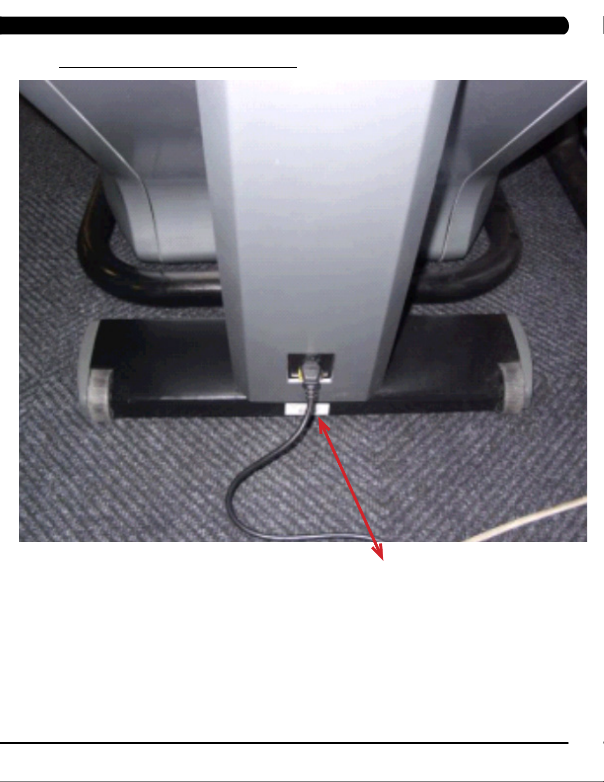
1.1 SERIAL NUMBER LOCATION
CHAPTER 1: SERIAL NUMBER LOCATION
SERIAL NUMBER LOCATION
1
Page 5
CHAPTER 1: SERIAL NUMBER LOCATION
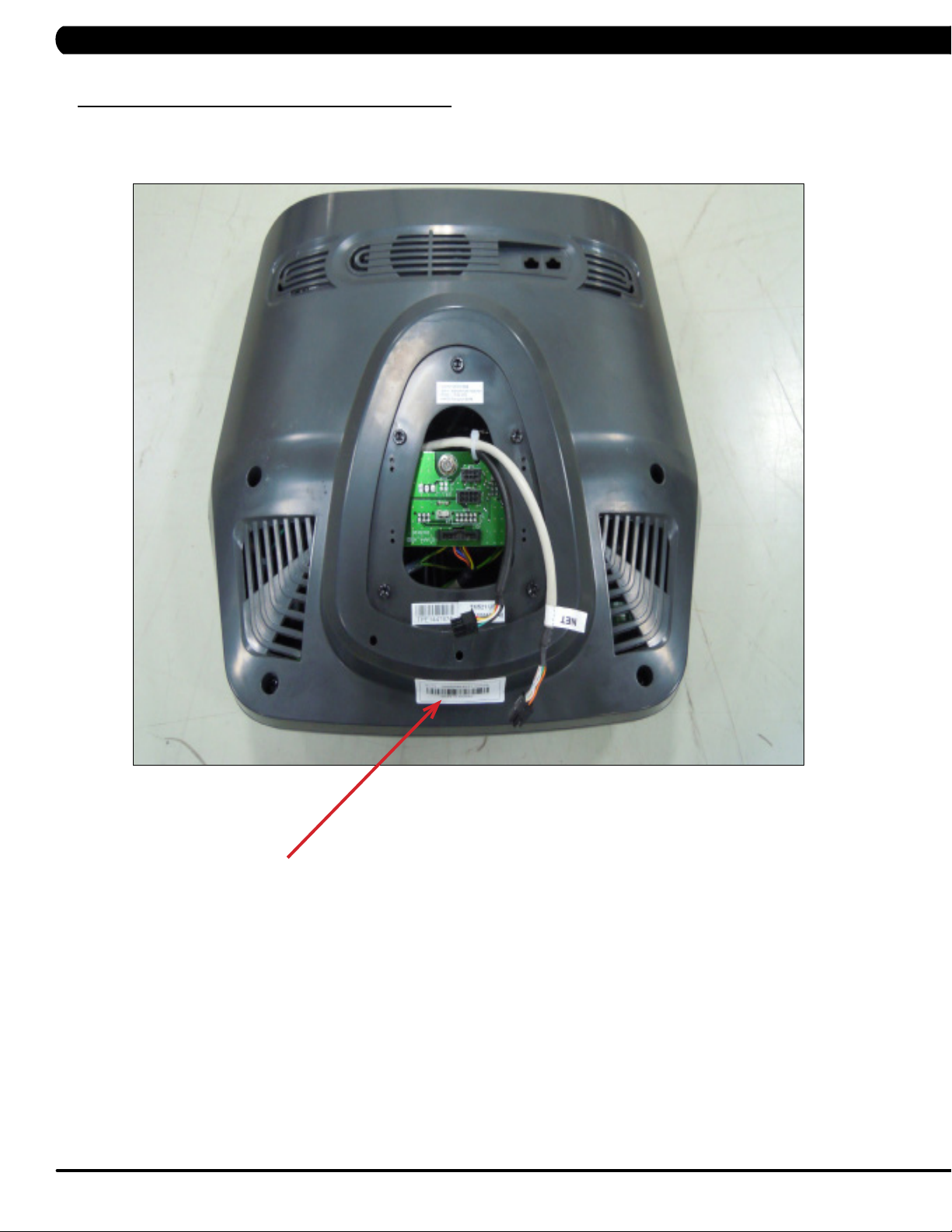
1.1 SERIAL NUMBER LOCATION - CONTINUED
console serial number location
CONSOLE SERIAL NUMBER LOCATION
2
Page 6

CHAPTER 2: IMPORTANT SAFETY INSTRUCTIONS
2.1 READ AND SAVE THESE INSTRUCTIONS
This Climb Mill is intended for commercial use. To ensure your safety
and protect the equipment, read all instructions before operating the
MATRIX Climb Mill.
When using an electrical product, basic precautions should always be
followed including the following:
• Anapplianceshouldneverbeleftunattendedwhenplugged
in. Unplugtheunitfromtheoutletwhennotinuseandbefore
puttingonortakingoffanyparts.
• Thisproductmustbeusedforitsintendedpurpose
describedinthisservicemanual. Donotuseother
attachmentsthatarenotrecommendbythemanufacturer.
Attachmentsmaycauseinjury.
• Topreventelectricalshock,neverdroporinsertanyobject
intoanyopening.
• Donotremovethesidecovers.Serviceshouldonlybedone
byanauthorizedservicetechnician.
• Neveroperatetheunitwiththeairopeningblocked.Keep
theairopeningclean,freeoflintandhair.
• Neveroperatetheunitifithasadamagedcordorplug,ifit
isnotworkingproperly,ifithasbeendamaged,orimmersed
inwater.
• Closesupervisionisnecessarywhentheunitisusedbyor
nearchildrenordisablepersons.
CAUTION! Ifyouexperiencechestpains,nausea,dizziness,or
shortnessofbreath,stopexercisingimmediatelyandconsult
yourphysicianbeforecontinuing.
CAUTION! Anychangesormodificationstothisequipment
couldvoidtheproductwarranty.
• Donotuseoutdoors.
• Donotoperatewhereaerosol(spray)productsarebeing
usedorwhenoxygenisbeingadministered.
• Donotusetheequipmentinanywayotherthandesignedor
intendedbythemanufacturer.ItisimperativethatallMatrix
FitnessSystemsequipmentisusedproperlytoavoidinjury.
• Keephandsandfeetclearofmovingpartsatalltimesto
avoidinjury.
• Unsupervisedchildrenmustbekeptawayfromthisequip
ment.
• Donotwearlooseclothingwhileontheequipment.
*AtNOtimeshouldpetsorchildrenundertheageof13be
closertotheunitthan10feet.
3
Page 7
CHAPTER 2: IMPORTANT SAFETY INSTRUCTIONS
2.2 ELECTRICAL REQUIREMENTS
DEDICATED CIRCUIT AND ELECTRICAL INFO
A “Dedicated Circuit” means that each outlet you plug into should not have anything else running on that same circuit. The easiest way to verify
this is to locate the main circuit breaker box, and turn off the breaker(s) one at a time. Once a breaker has been turned off, the only thing that
should not have power to it are the units in question. No lamps, vending machines, fans, sound systems, or any other item should lose power
when you perform this test.
Non-looped (isolated) neutral/grounding means that each circuit must have an individual neutral/ground connection coming from it, and
terminating at an approved earth ground. You cannot “jumper” a single neutral/ground from one circuit to the next.
ELECTRICAL REQUIREMENTS
For your safety and to ensure good unit performance, the ground on this circuit must be non-looped (isolated). Please refer to NEC article 21021 and 210-23. Any alterations to the standard power cord provided could void all warranties of this product.
The 3x, 5x and 7xe
external power supply, the console’s start-up time may be delayed. Add-on TV’s and other console accessories will increase the time needed
for start-up. An external power supply will ensure power is provided to the console at all times and is recommended when add-on accessories
are used.
For units with an integrated TV (like the 7xe and 7xi), the TV power requirements are included in the unit. An RG6 coaxial cable with ‘F Type’
compression fittings on each end will need to be connected to the cardio unit and the video source. Additional power requirements are not
needed for the add-on digital TV (3x and 5x). For units with an add-on PCTV (3x and 5x), the TV power requirements are separate.
NOTE: ALL UNITS WITH VIRTUAL ACTIVE™ MUST BE POWERED!
Climbmills are designed to be self-powered and do not require an external power supply source to operate. Without an
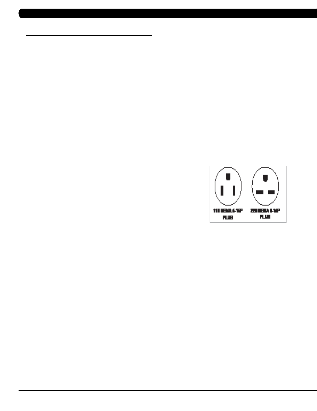
110 V UNITS
All Matrix 3x, 5x, 7xe and 7xi 110 V Climbmills require the use of a 100-125 V, 60 Hz and a 15 A
“Dedicated Circuit”, with a non-looped (isolated) neutral/ground for power. This outlet should be a
NEMA 5-15R and have the same configuration as the plug. No adapter should be used with this
product. These bikes can be daisy-chained together with up to 4 units per 15 A dedicated circuit.
Matrix daisy-chain cord adapters are sold separately.
220 V UNITS
All Matrix 3x, 5x, 7xe and 7xi 220 V Climbmills require the use of a 216-250 V, 50 Hz and a 15 A
“Dedicated Circuit”, with a non-looped (isolated) neutral/ground for power. This outlet should be a
NEMA 6-15R and have the same configuration as the plug. No adapter should be used with this
product. These bikes can be daisy-chained together with up to 4 units per 15 A dedicated circuit.
Matrix daisy-chain cord adapters are sold separately.
GROUNDING INSTRUCTIONS
The unit must be grounded. If it should malfunction or breakdown, grounding provides a path of least resistance for electric current to reduce
the risk of electric shock. The unit is equipped with a cord having an equipment-grounding conductor and a grounding plug. The plug must be
plugged into an appropriate outlet that is properly installed and grounded in accordance with all local codes and ordinances. If the user does
not follow these grounding instructions, the user could void the Matrix limited warranty.
ADDITIONAL ELECTRICAL INFO
In addition to the dedicated circuit requirement, the proper gauge wire must be used from the circuit breaker box, to each outlet that will have
the maximum number of units running off of it. If the distance from the circuit breaker box to each outlet, is 100 ft (30.5 m) or less, then 12
gauge wire should be used. For distances greater than 100 ft (30.5 m) from the circuit breaker box to the outlet, a 10 gauge wire should be
used.
North American power cord plugs shown.
Depending on your country, the plug type may vary.
ENERGY SAVING / LOW- POWER MODE
All units are configured with the ability to enter into an energy saving / low-power mode when the unit has not been in use for a specified period
of time. Additional time may be required to fully reactivate this unit once it has entered the low-power mode. This energy saving feature may be
enabled or disabled from within the ‘Manager Mode’ or ‘Engineering Mode.
4
Page 8
CHAPTER 2: IMPORTANT SAFETY INSTRUCTIONS
2.3 LOCATING THE UNIT
LOCATION OF THE UNIT:
Place the unit on a level surface and away from direct sun light. The intense UV light can cause discoloration of plastics. Locate in an area
with cool temperatures and low humidity. Leave a clear zone behind the unit of at least 24". This zone must be clear of any obstruction and
allow the user a clear exit path from the unit. Do not place the unit in any area that will block the openings or vents. The unit should not be
used in a garage or covered patio.
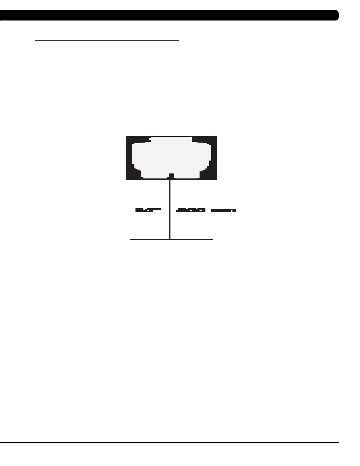
HeightRequirements - The Climb Mill adds 30" - 38" (76 - 96cm) to a user's height. For example, a 6' (183cm) tall user will be 7'8"
(234.4cm - 254.4cm) off the floor. Total height of the user on the Climb Mill should not exceed 9'10" (300 cm), which means that users taller
than 6'8" (204cm) should not use this equipment.
5
Page 9
CHAPTER 3: PREVENTATIVE MAINTENANCE
3.1 RECOMMENDED CLEANING TIPS
In order to maximize life span, and minimize down time, all Matrix Fitness Equipment requires regularly
scheduled cleaning.
YOU WILL NEED:
- Mild dish soap and water mixture in a spray bottle (10:1 water to soap ratio).
- Lint free 100% cotton cleaning cloths or Micro fiber cleaning cloths.
- Vacuum / Shop Vac with extendable hose and soft brush attachment.
- iPod corrosion blocker - Available from Matrix (part # ZMS4001374).
- Super Lube Multi Purpose Synthetic Lubricant with Syncolon® (PTFE) Aerosol - www.super-lube.com/sythetic-aerosol-spray-ezp-46.html.
- Corrosion Block (available from Matrix - part # ZMS4001374).
- LCD / LED or computer screen cleaner.
DAILY or as needed:
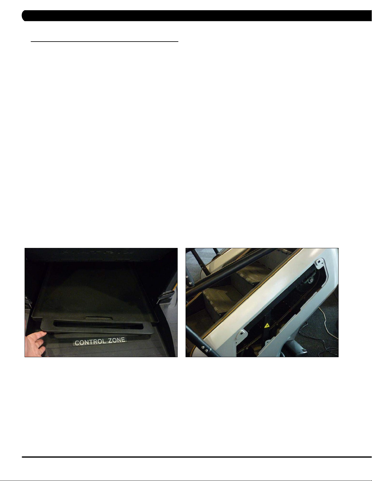
1. Empty the dust tray under the stairs and under the unit (Figure A). If you need to move the unit, unplug it first.
WEEKLY:
1. With a clean dry 100% lint free cloth and water / soap mixture, wipe down the entire frame including the stairs so it is free of dust, dirt, and
sweat.
2. With a clean dry 100% lint free cloth and water / soap mixture, wipe down the entire console area including the hand grips and hand rails.
MONTHLY:
1. Vacuum under and around the Climb Mill If you need to move the unit, unplug it first. Make sure to reset the casters after moving the unit
back into position to stabilize the unit.
2. Apply corrosion block to the metal part of the iPod cable.
3. Use a computer screen cleaner or LCD / LED screen cleaner on the touch screen portion of the console (see Section 3.3).
QUARTERLY:
1. Remove the side access panels and vacuum out the inside of the unit (Figure B).
FIGURE A FIGURE B
6
Page 10

CHAPTER 3: PREVENTATIVE MAINTENANCE
3.2 CARE AND MAINTENANCE INSTRUCTION
In order to maximize life span, and minimize down time, all MATRIX equipment requires regular cleaning, and maintenance items performed on
a scheduled basis. This section contains detailed instructions on how to perform these items, the frequency of which they should be done, and a
check list to sign off each time service is completed for a specific machine. Some basic tools and supplies will be necessary to perform these tasks
which include (but may not be limited to):
* Metric Allen wrenches
* #2 Phillips head screwdriver
* Adjustable wrench
* Teflon based spray lubricant such as “Super Lube”, or other Matrix approved product
You may periodically see addendums to this document, as the Matrix Technical Support Team identifies items that require specific attention, the
latest version will always be available on the Matrix website, www.matrixfitness.com
DAILY MAINTENANCE ITEMS
1. Attempt to wobble the unit from side to side and front to back. Level the unit if needed (See Section 10.4).
QUARTERLY MAINTENANCE ITEMS
1. Check all connecting joint areas for tightness of fastened assemblies.
2. Remove the maintenance cover and check the fans for function. Also clean and remove any debris from the digital speed sensor.
3. Remove the maintenance cover and check the chains for damage, alignment and proper tension.
4. On units with a Control Zone, check to ensure the CZ is working properly by walking on the unit, then stepping on the CZ. The unit should stop
similar to an emergency stop on a treadmill.
7
Page 11

CHAPTER 3: PREVENTATIVE MAINTENANCE
3.3 TOUCH SCREEN CARE & CLEANING
TOUCH SCREEN CARE AND CLEANING
* The touch screen requires very little maintenance. We recommend that you periodically clean the touch screen surface with a clean dry 100%
lint free cloth and water / soap mixture or a computer or LCD / LED screen cleaner.
* It is very important to avoid using any other chemical on the touch screen.
* Always dampen the cloth and clean the screen. Do not spray the water / soap mixture on the screen itself, the drips can seep into the display
or stain the bezel.
* After cleaning, make sure the surface is dry. There should not be any left over solvent to seep into the display.
* It is very important to handle the touch screen with care. Do not use excessive force when cleaning.
* Do not use any sharp materials to clean the touch screen surfaces.
* Do not use high pressure air, water, or steam to clean the touch screen surface.
8
Page 12

CHAPTER 4: CONSOLE OVERLAY AND WORKOUT DESCRIPTION
4.1 CONSOLE DESCRIPTION
The C7xi has a fully integrated touch screen display. All information required for workouts is explained on screen. Exploration of the interface is
highly encouraged. The information explaining how to program for various workouts will give an explanation about the contents of each screen.
Go: One touch Start.
stoP: Ends workout and shows workout summary data.
cool DoWn
Workouts 19 minutes and shorter will have a cool down length of 2 minutes. Workouts 20 minutes and longer will have a cool down length of 5
minutes.
(displayed on-screen during workout): Puts unit into Cool Down mode. Cool Down time is dependent on the length of the workout.
C7Xi ENTERTAINMENT ZONE
iPOD®: Will take the user directly to the iPod screen to allow for iPod control and play list selection.
Volume uP / DoWn: Adjusts the volume output through the headphone jack of the integrated console TV or iPod output.
NUMBERKEYPAD: Allows for easy TV channel selections.
cHannel uP / DoWn: Allows for channel selection.
DISPLAYMODE: Allows user to cycle through console display options, iPod, TV, or profile display.
last cHannel: Allows the user to cycle between the current channel and the previous channel viewed.
cc/mute:
Mutes sound and turns closed captioning on or off.
9
Page 13
CHAPTER 4: CONSOLE OVERLAY AND WORKOUT DESCRIPTION
4.2 WORKOUT SETUP STEPS
To set up a workout, press the touch screen over the program you would
like to use and then follow the prompts to begin your workout.
Go - Press to immediately begin a workout. Workout, resistance level,
and time will automatically go to default settings. All energy expenditure
values will be calculated using the default weight measurement.
manual - Manual allows the user to input more information while
defining their own workout. Calorie expenditure will be more accurate
when inputting information in Manual than by pressing GO.
rollinG Hills - The Rolling Hills program is a level based
program that automatically adjusts the resistance level to simulate real
terrain.
interVals - The Intervals program is a level based program that
automatically adjusts the resistance of the machine from low to high
intensity settings at regular intervals to burn calories.
Goal traininG - The Goal Training program is designed to help
users burn a target number of calories.
calorie traininG - The Calorie Training program is designed
to help users burn a target number of calories.
constant Watts - The Constant Watts program allows
you to vary your cadence or SPM and the machine's resistance will
adjust according to your selected goal. The quicker you step, the less
resistance for the goal selected.
Fat burn - The Fat Burn program is a level based workout that is
designed to help users burn fat through various resistance changes.
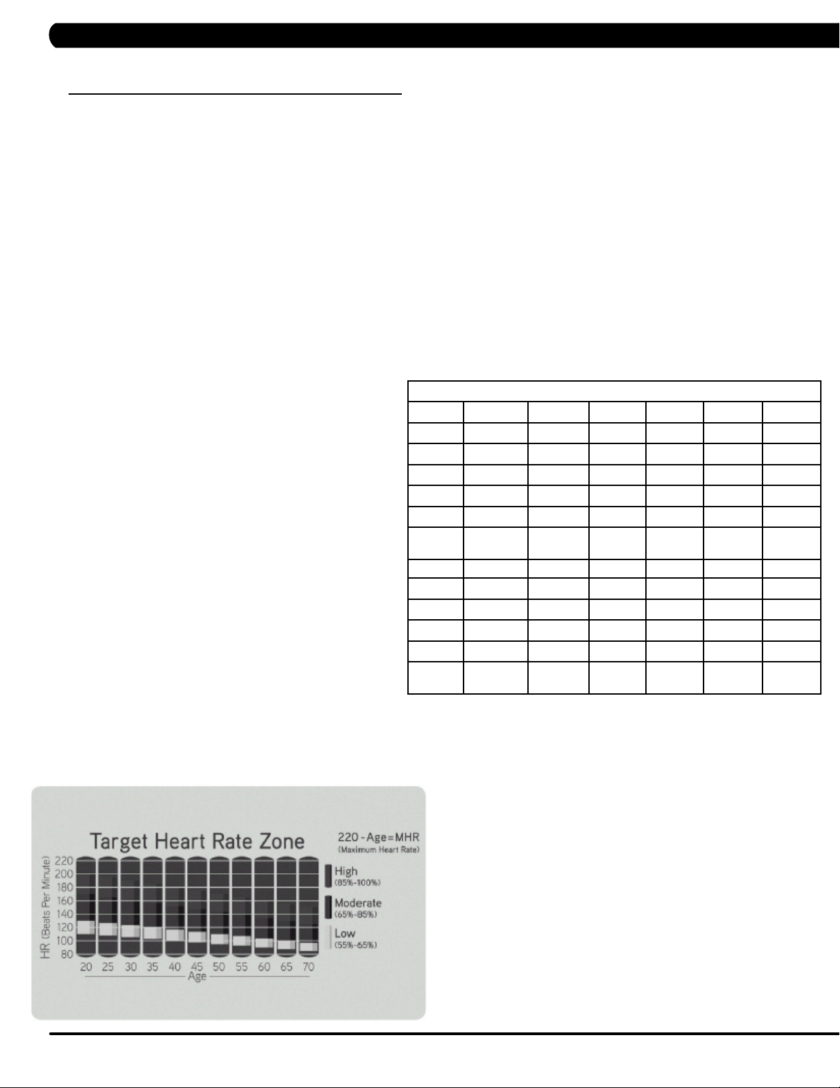
tarGet Heart rate - The Matrix Climb Mill comes with
standard digital contact heart rate sensors and are POLAR telemetry
compatible. The heart rate control workout mode allows the user
to program their desired heart rate zone, and the Climb Mill will
automatically adjust the level based upon the user's heart rate. The
heart rate zone is calculated using the following equation: (220-Age)*% =
target heart rate zone. The user must wear a POLAR telemetric strap or
continually hold onto the contact heart rate grips for this workout.
Locate the metal sensors on the handlebars of the Climb Mill. Notice
that there are two separate pieces of metal on each grip. You must be
making contact with both pieces of each grip to get an accurate heart
rate reading. You can grab these sensors in any program to view your
current heart rate.
FITNESSTEST(WFI) - The WFI (Wellness Fitness Initiative)
protocol is a test used by firefighters in a series of intervals lasting a
maximum of 16 minutes, where the speed is increased every minute
until the Target Heart Rate is exceeded for 15 seconds. When the
test is complete, the display provides a summary of V)2max, Highest
SPM, Elapsed Time, and Target Heart Rate. The test requires constant
monitoring of the user's heart rate, so the use of a telemetric heart rate
strap is highly recommended.
FITNESSTEST(SUBMAXIMAL)- The Submaximal test
measures cardiovascular fitness and provides an estimated Sub-maximal
VO2 max result. This assessment is a 4 stage test lasting 3-5 minutes
where the speed is increased until your Heart Rate is between 115 - 150
bpm for 2 of the stages. When the test is complete, a Fitness Rating is
displayed as High, Good, Average, Fair, or Low along with your age and
VO2 max. The test requires constant monitoring of the user's heart rate,
so the use of a telemetric heart rate strap is highly recommended.
FITNESS RATING NORMS (V02 MAX)
AGE 20-29 30-39 40-49 50-59 60+
MEN
HIGH 51.4+ 50.4+ 48.2+ 45.3 42.5+
GOOD 51.3-46.8 50.3-44.6 48.1-41.8 45.2-38.5 42.4-35.3
AVERAGE 46.7-42.5 44.5-41.0 41.7-38.1 38.4-35.2 35.2-31.8
FAIR 42.4-39.5 40.9-37.4 38.0-35.1 35.1-32.3 31.7-28.7
LOW 39.4 OR
LESS
WOMEN
HIGH 44.2+ 41.0+ 39.5+ 35.2+ 35.2
GOOD 44.1-38.1 40.9-36.7 39.4-33.8 35.1-30.9 35.1-29.4
AVERAGE 38.0-35.2 36.6-33.8 33.7-30.9 30.8-28.2 29.3-25.8
FAIR 35.1-32.3 33.7-30.5 30.8-28.3 28.1-25.5 25.7-23.8
LOW 32.2 OR
LESS
37.3 OR
LESS
30.4 OR
LESS
35.0 OR
LESS
28.2 OR
LESS
32.2 OR
LESS
25.4 OR
LESS
28.6 OR
LESS
23.7 OR
LESS
10
Page 14
5.1 USING MANAGER MODE
CHAPTER 5: MANAGER MODE
1) To enter Manager Mode, press "ENTER, 1, 0, 0, 1, ENTER" on the number keypad and Manager Mode will appear on the display.
2) Manager Mode is divided into 9 tabs, located on the left side of the screen. They are General, Workout, Setup Defaults, Asset Management,
Weather, TV, Applications, Hardware and Service.
3) Choose a tab by touching the screen over the desired tab.
4) Each of the tabs has options that will appear once you have chosen that particular tab.
5) Press the "HOME" button or the EMERGENCY STOP to exit Manager Mode.
11
Page 15
CHAPTER 5: MANAGER MODE
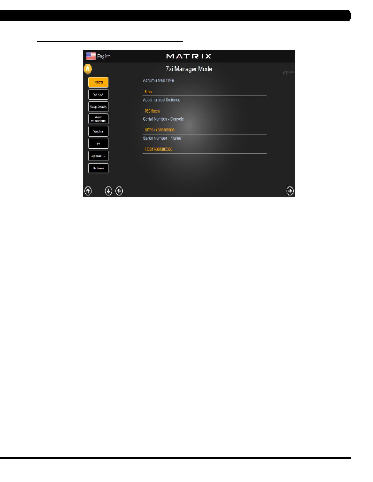
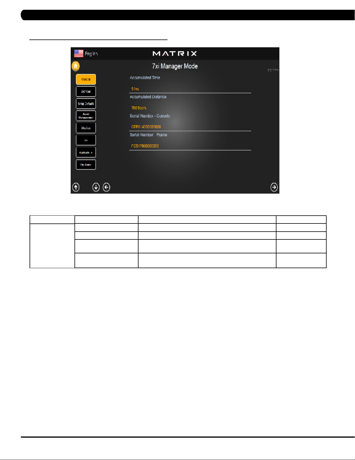
5.2 MANAGER MODE – GENERAL – TAB 1
MANAGER MODE
General
FUNCTION & DEFAULTS DESCRIPTIONS MODIFIED
Accumulated Time Total time on the unit since production. Cannot be modified.
Accumulated Distance Total distance on the unit since production. Cannot be modified.
Serial Number - Console This option displays the serial number of the console, not
editable (see Service Mode to change serial numbers).
Serial Number - Frame This option displays the serial number of the platform, not
editable (see Service Mode to change serial numbers).
Cannot be modified.
Cannot be modified.
12
Page 16
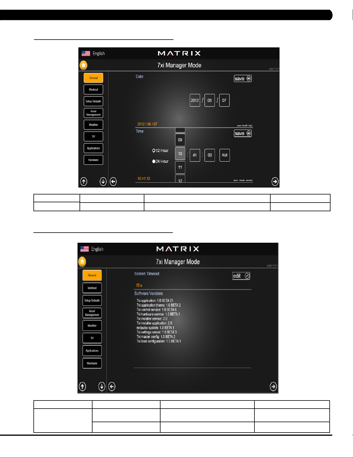
5.2 MANAGER MODE - GENERAL – TAB 2
CHAPTER 6: MANAGER MODE
MANAGER MODE
General
5.2 MANAGER MODE - GENERAL – TAB 3
FUNCTION & DEFAULTS DESCRIPTIONS MODIFIED
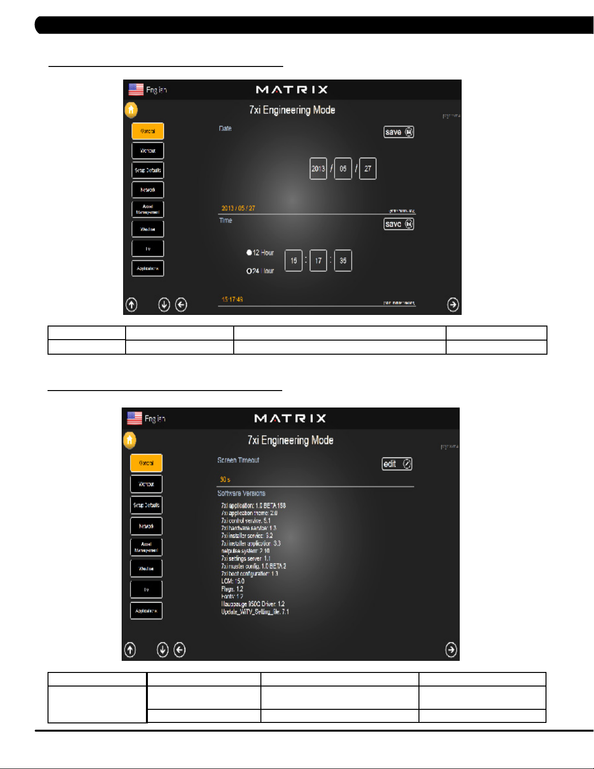
Date & Time This option sets the current date and time of the machine. N/A
MANAGER MODE
General
FUNCTION & DEFAULTS DESCRIPTIONS MODIFIED
Screen Timeout This option sets the machine show the
workout time of the machine.
Software Versions Software version. Cannot be modified.
Maximum: 120 sec
Maximum: 15 sec
13
Page 17
CHAPTER 5: MANAGER MODE
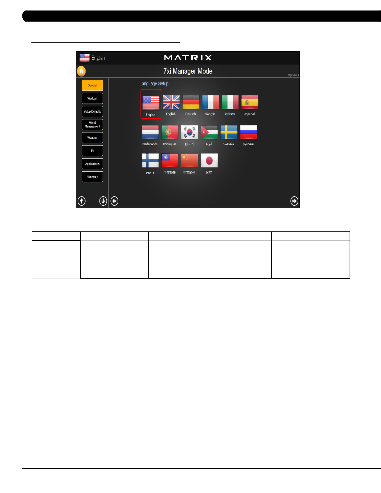
5.2 MANAGER MODE – GENERAL – TAB 4
MANAGER MODE
General
FUNCTION & DEFAULTS DESCRIPTIONS MODIFIED
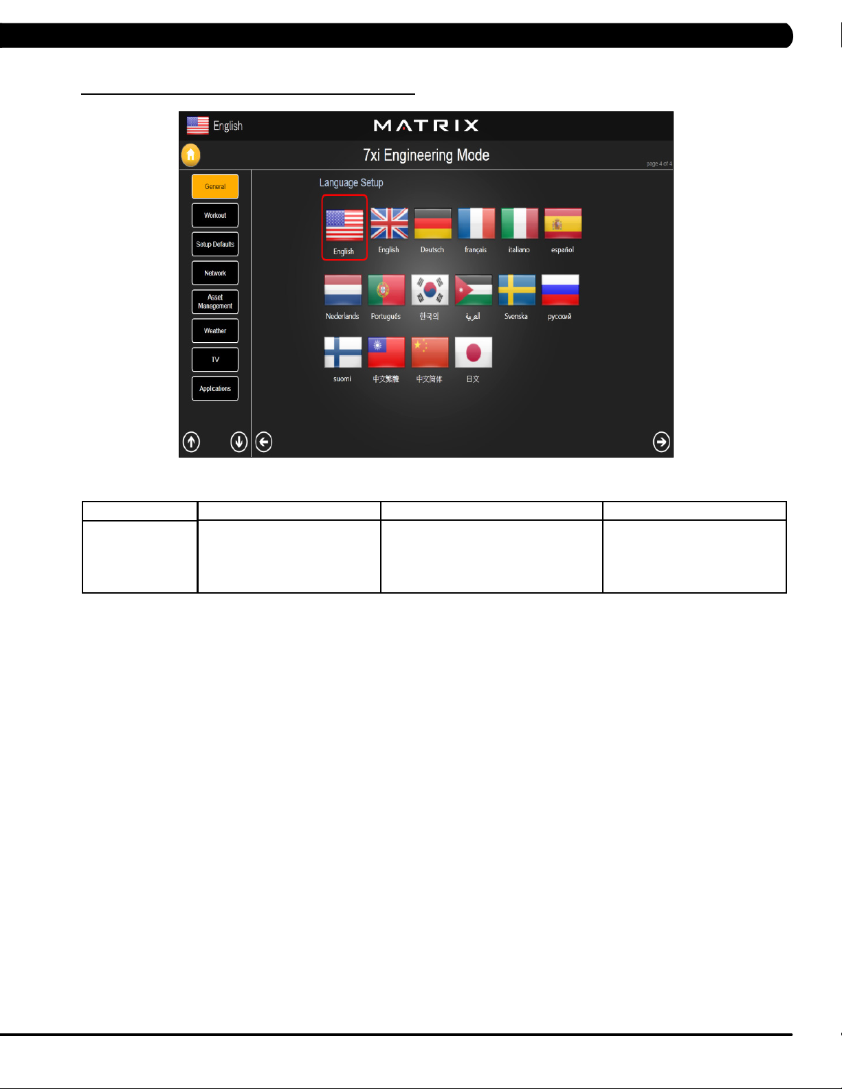
Language Setup Sets the language used on the console. English (US), English (UK),
German, French, Italian,
Spanish, Dutch, Portuguese,
Korean, Israeli, Swiss, Russian,
Finnish, Taiwanese, Chinese, or
Japanese.
14
Page 18
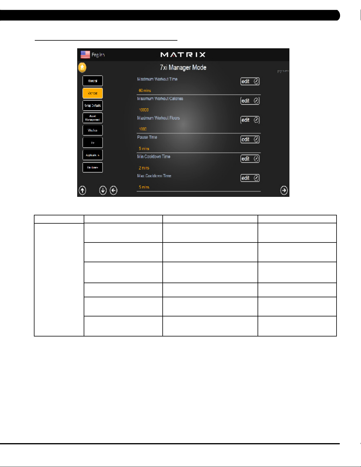
5.3 MANAGER MODE - WORKOUT – TAB 1
CHAPTER 5: MANAGER MODE
MANAGER MODE
Workout
FUNCTION & DEFAULTS DESCRIPTIONS MODIFIED
Maximum Workout Time This option allows the club to set the
maximum workout duration limits during
peak and non peak hours.
Maximum Workout Calories This option allows the club to set the
maximum workout duration limits during
peak and non peak hours.
Maximum Workout Floors This option allows the club to set the
maximum workout duration limits during
peak and non peak hours.
Pause Time This option controls the default pause time. Maximum: 10 Minutes
Min Cooldown Time This option allows the club to set the
minimum cool down duration limits during
peak and non peak hours.
Max Cooldown Time This option allows the club to set the
minimum cool down duration limits during
peak and non peak hours.
Maximum: 120 Minutes
Minimum: 10 Minutes
Maximum: 10000
Minimum: 50
Maximum: 10000
Minimum: 10
Minimum: 1 Minutes
Maximum: 5 Minutes
Minimum: 1 Minutes
Maximum: 10 Minutes
Minimum: 5 Minutes
15
Page 19
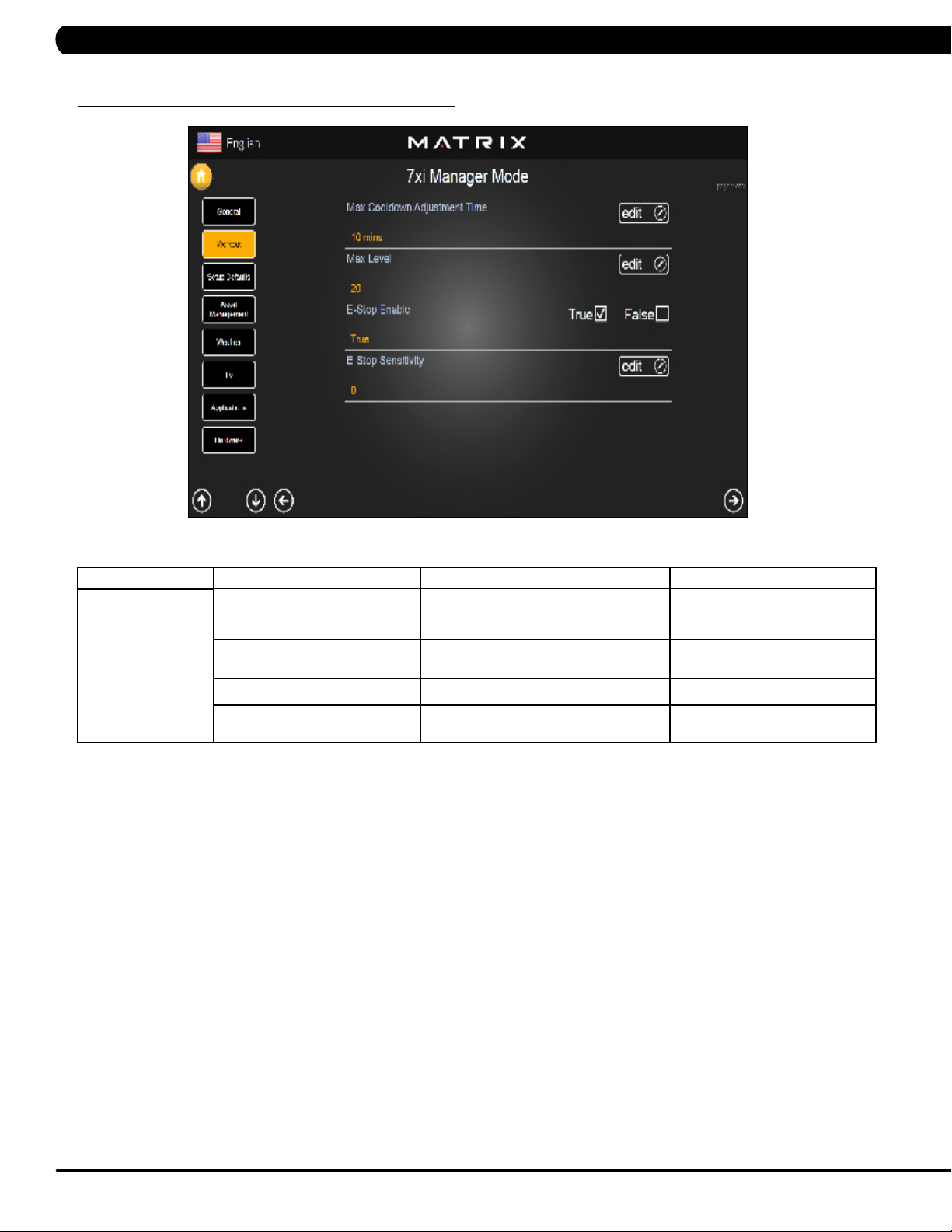
CHAPTER 5: MANAGER MODE
5.3 MANAGER MODE - WORKOUT – TAB 2
MANAGER MODE
Workout
FUNCTION & DEFAULTS DESCRIPTIONS MODIFIED
Max Cooldown Adjustment Time This option allows the club to set the
maximum cool down duration limits during
peak and non peak hours.
Max Level This option controls the default program
level.
E-Stop Enable This option controls the E-Stop function True / False
E-Stop Sensitivity This option controls the safety threshold
for the E-Stop function.
Maximum: 20 Minutes
Minimum: 5 Minutes
Maximum: 20
Minimum: 1
Maximum: 500
Minimum: 4
16
Page 20
CHAPTER 5: MANAGER MODE
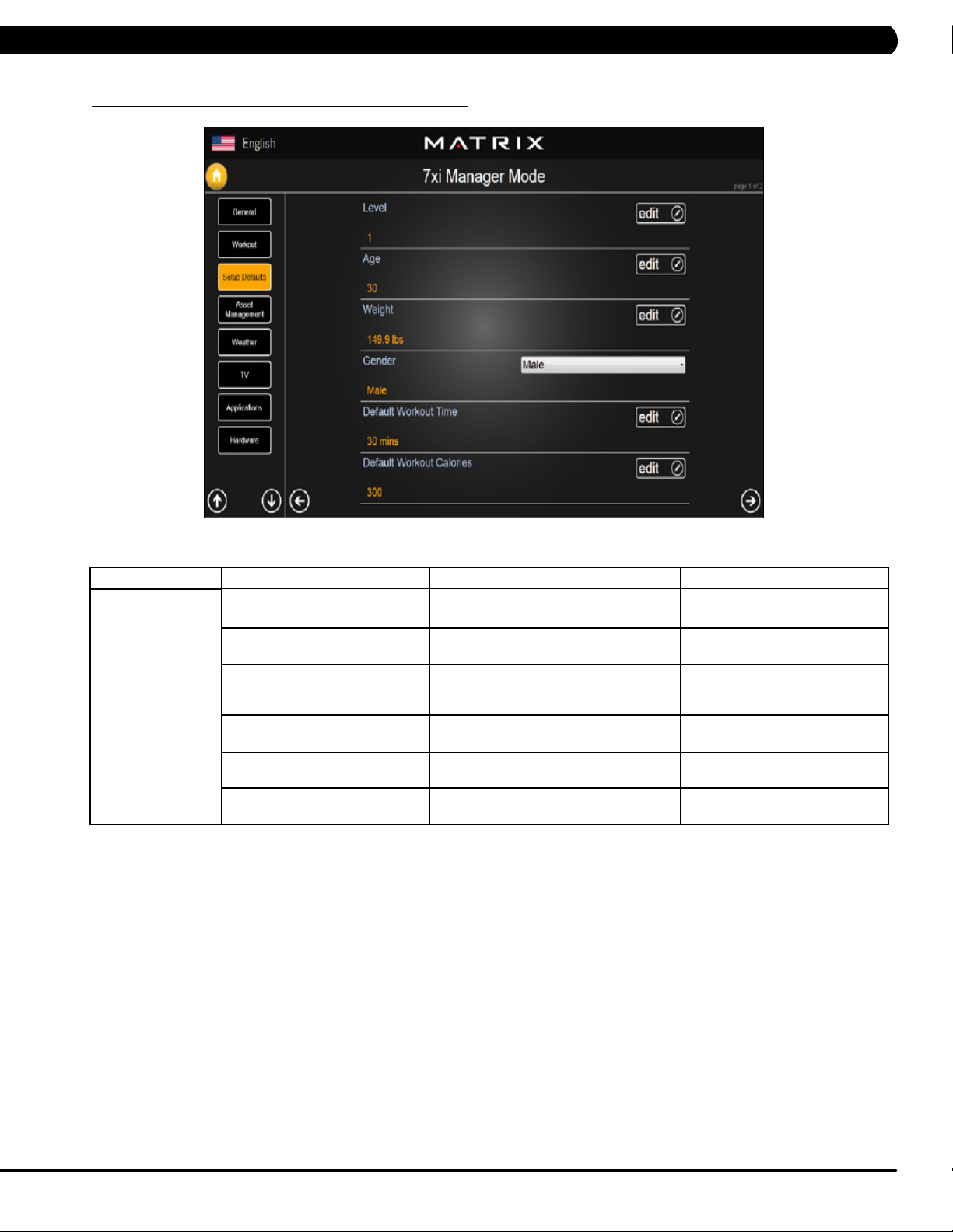
5.4 MANAGER MODE - SETUP DEFAULTS – TAB 1
MANAGER MODE
Setup Defaults
FUNCTION & DEFAULTS DESCRIPTIONS MODIFIED
Level This option controls the default program
levels.
Age This option controls the default user's age
used in the target heart rate calculations.
Weight This option controls the default weight
used in the calorie calculations. Displayed
in native units (pounds or kilograms).
Gender This option sets the user's gender as
either male or female.
Default Workout Time This option controls the default program
time.
Default Workout Calories This option controls the default program
calories.
Maximum: 20
Minimum: 1
Maximum: 99
Minimum: 10
79~401 lbs
Male or Female
Maximum: 60
Minimum: 5
Maximum: 5000
Minimum: 50
17
Page 21
CHAPTER 5: MANAGER MODE
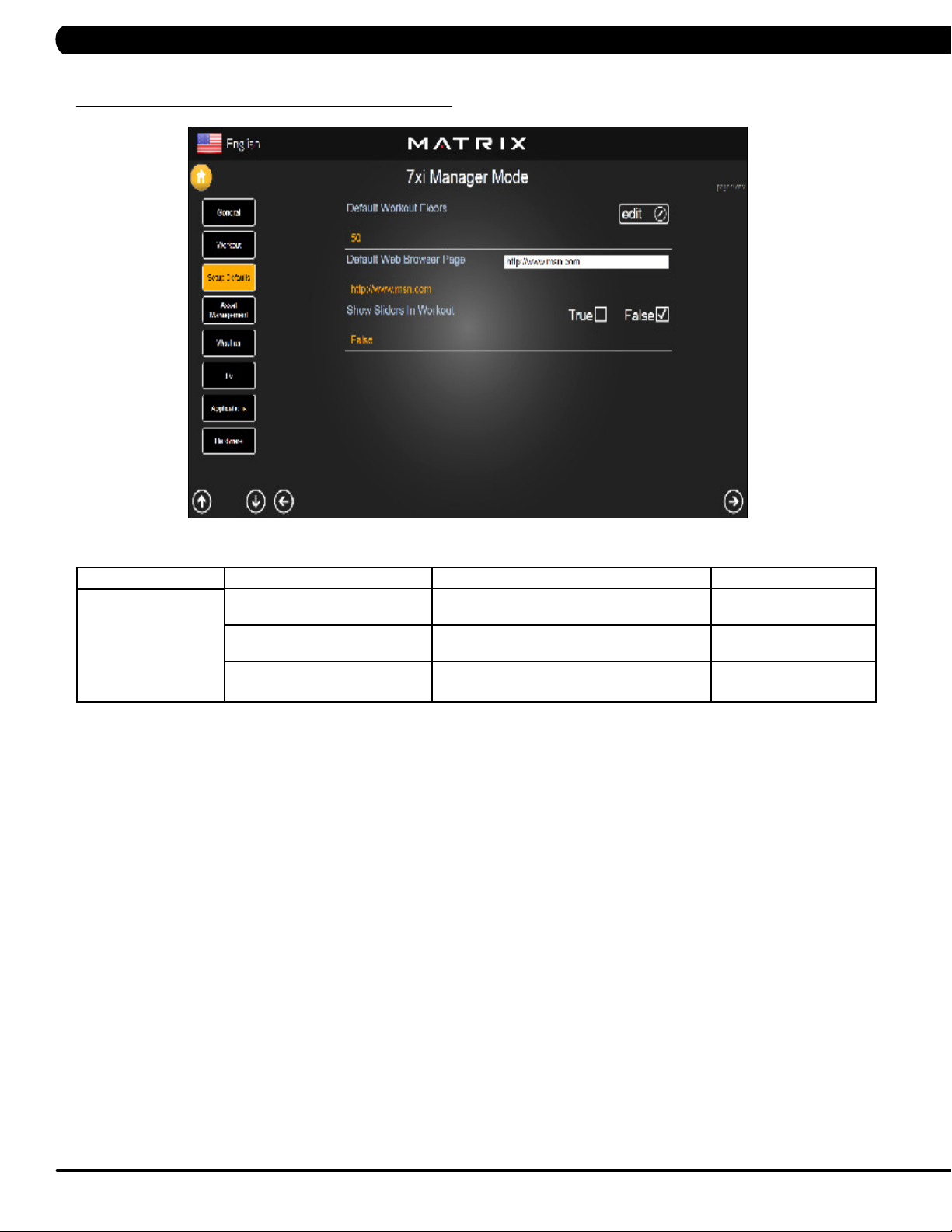
5.4 MANAGER MODE - SETUP DEFAULTS – TAB 2
MANAGER MODE
Setup Defaults
FUNCTION & DEFAULTS DESCRIPTIONS MODIFIED
Default Workout Floors This option controls the default program
Distance.
Default Web Brower Page This option controls the default machine Web
Brower Page.
Show Sliders In Workout This option controls the default Sliders bar of
True or False.
Maximum: 10000
Minimum: 10
N/A
True or False
18
Page 22

CHAPTER 5: MANAGER MODE
5.5 MANAGER MODE - ASSET MANAGEMENT
MANAGER MODE
Asset Management
5.6 MANAGER MODE - WEATHER
FUNCTION & DEFAULTS DESCRIPTIONS MODIFIED
Club ID This option records the club ID of the
Show Custom Logo This option allows the user to select the
fitness facility.
N/A
True or False
screen Logo from True
MANAGER MODE
Weather
FUNCTION & DEFAULTS DESCRIPTIONS MODIFIED
Default City This option controls the default City Weather. N/A
Enable Alerts This option controls the City Weather function True or False. True or False
Weather Temperature Unit This option controls how temperature is displayed. Fahrenheit or Celsius
19
Page 23
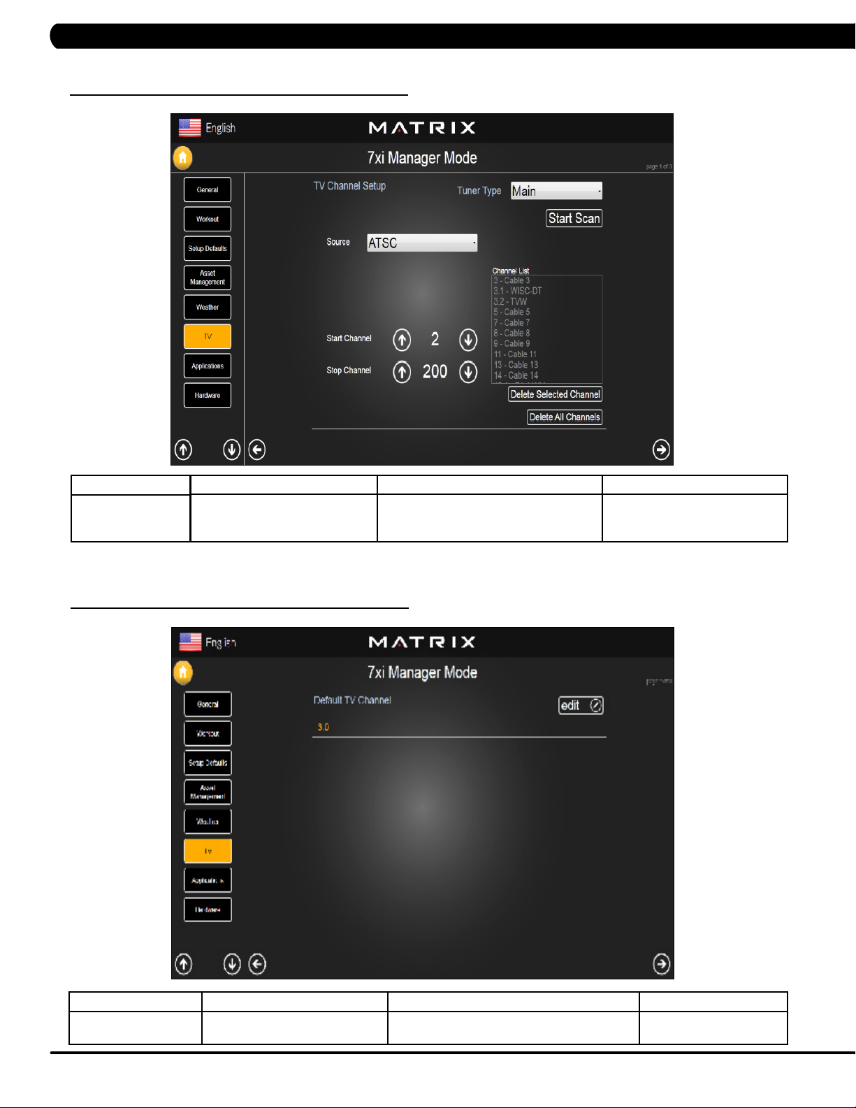
5.7 MANAGER MODE - TV – TAB 1
CHAPTER 5: MANAGER MODE
MANAGER MODE
TV
5.7 MANAGER MODE - TV – TAB 2
FUNCTION & DEFAULTS DESCRIPTIONS MODIFIED
TV Channel Setup This option is for setting the TV tuner
functions. Press the "Start Scan" to search
N/A
the TV Channel.
20
MANAGER MODE
TV
FUNCTION & DEFAULTS DESCRIPTIONS MODIFIED
Default TV Channel This option controls the default TV channel on
start up.
Maximum: 1000
Minimum: 2
Page 24
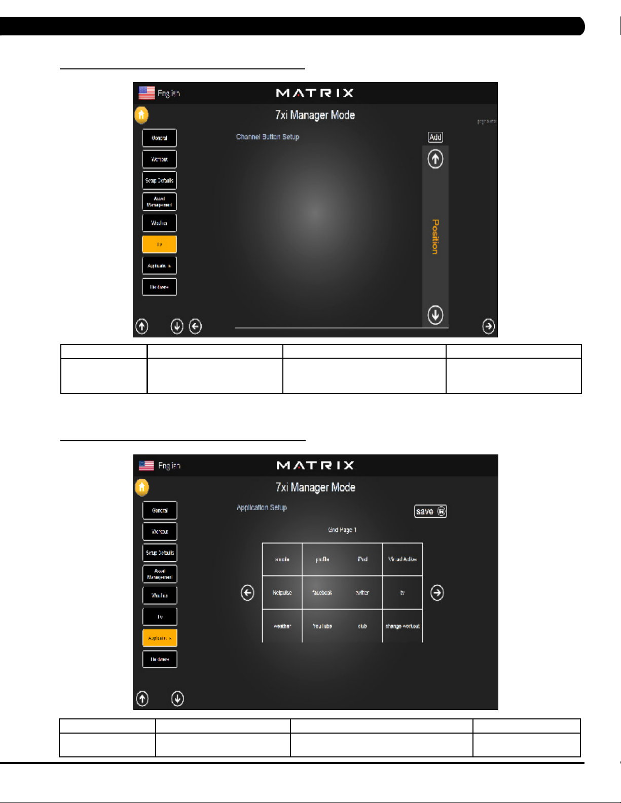
5.7 MANAGER MODE - TV – TAB 3
CHAPTER 5: MANAGER MODE
MANAGER MODE
TV
5.8 MANAGER MODE - APPLICATIONS
FUNCTION & DEFAULTS DESCRIPTIONS MODIFIED
Channel Button Setup This option is for setting the TV channel
button. Press the "Add" to edit the channel
N/A
icon, channel name and channel.
MANAGER MODE
Applications
FUNCTION & DEFAULTS DESCRIPTIONS MODIFIED
Application Setup This option is for setting the screen table
functions.
N/A
21
Page 25
CHAPTER 5: MANAGER MODE
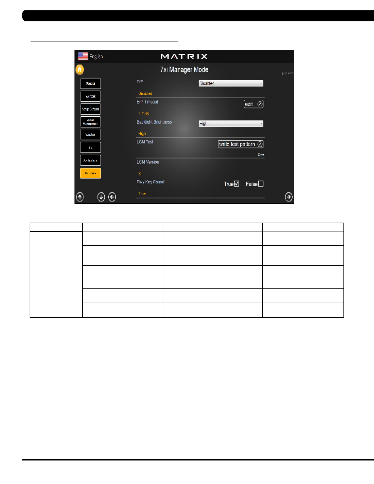
5.9 MANAGER MODE - HARDWARE – TAB 1
MANAGER MODE
Hardware
FUNCTION & DEFAULTS DESCRIPTIONS MODIFIED
ErP This option controls the ErP function is
Disabled or Enabled.
ErP Timeout Console will enter ErP mode if user does
not touch the screen or press any key pad
for couple minutes.
Backlight Brightness This option controls the screen backlight
Brightness.
LCM Test Write test pattern.
LCM Version Software version. Cannot be modified.
Play Key Sound This option can set the keypad tone to
sound or not sound.
Disabled or Enabled
Maximum: 60
Minimum: 1
Low / Medium / High
N/A
True or False
22
Page 26
CHAPTER 5: MANAGER MODE
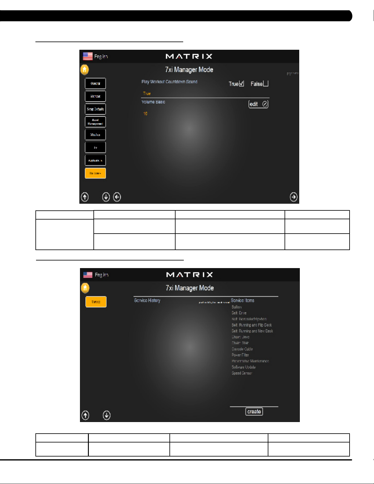
5.9 MANAGER MODE - HARDWARE – TAB 2
MANAGER MODE
Hardware
5.10 MANAGER MODE - SERVICE
FUNCTION & DEFAULTS DESCRIPTIONS MODIFIED
Play Workout Countdown Sound This option can set the play workout countdown
Volume Basic This option controls the default volume on start
to sound or not sound.
up.
True or False
Maximum: 30
Minimum: 0
MANAGER MODE
Service
FUNCTION & DEFAULTS DESCRIPTIONS MODIFIED
Service History This option allows the club to record key
components replacement history.
N/A
23
Page 27
6.1 USING ENGINEERING MODE
CHAPTER 6: ENGINEERING MODE
1) To enter Engineering Mode, press "ENTER, 2, 0, 0, 1, ENTER" on the number keypad and Engineering Mode will appear on the display.
2) Engineering Mode is divided into 12 tabs, located on the left side of the screen. They are General, Workout, Setup Defaults, Network, Asset
Management, Weather, TV, Applications, Calibration, Hardware, Service, Errors.
3) Choose a tab by touching the screen over the desired tab.
4) Each of the tabs has options that will appear once you have chosen that particular tab.
5) Press the "HOME" button or the EMERGENCY STOP to exit Engineering Mode..
24
Page 28
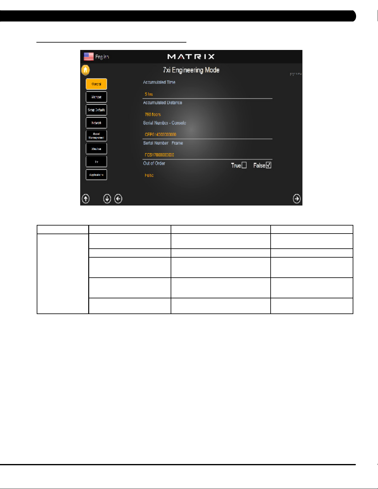
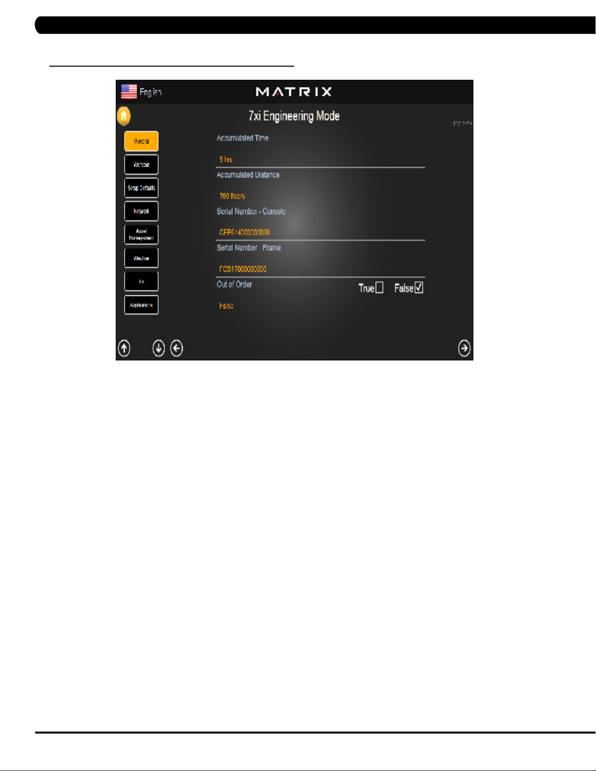
CHAPTER 6: ENGINEERING MODE
6.2 ENGINEERING MODE - GENERAL – TAB 1
MANAGER MODE
General
FUNCTION & DEFAULTS DESCRIPTIONS MODIFIED
Accumulated Time Total time on the unit since production. Cannot be modified.
Accumulated Distance Total distance on the unit since production. Cannot be modified.
Serial Number - Console This option displays the serial number of
the console. See Service Mode to edit the
serial numbers.
Serial Number - Frame This option displays the serial number of
the Frame. See Service Mode to edit the
serial numbers.
Out of Order This option allows the club to show the unit
"out of order" if an error is present.
Cannot be modified.
Cannot be modified.
True / False
25
Page 29
CHAPTER 6: ENGINEERING MODE
6.2 ENGINEERING MODE - GENERAL – TAB 2
MANAGER MODE
General
6.2 ENGINEERING MODE - GENERAL – TAB 3
FUNCTION & DEFAULTS DESCRIPTIONS MODIFIED
Date & Time This option sets the current date and time of the machine. N/A
26
MANAGER MODE
General
FUNCTION & DEFAULTS DESCRIPTIONS MODIFIED
Screen Timeout This option sets the machine show the
workout time of the machine.
Software Versions Software versions. Cannot be modified.
Maximum: 120 sec
Minimum: 15 sec
Page 30
CHAPTER 6: ENGINEERING MODE
6.2 ENGINEERING MODE - GENERAL – TAB 4
MANAGER MODE
General
FUNCTION & DEFAULTS DESCRIPTIONS MODIFIED
Language Setup Sets the language used on the console. English (US), English (UK),
German, French, Italian, Spanish,
Dutch, Portuguese, Korean,
Israeli, Swiss, Russian, Finnish,
Taiwanese, Chinese, or Japanese.
27
Page 31

CHAPTER 6: ENGINEERING MODE
6.3 ENGINEERING MODE - WORKOUT – TAB 1
MANAGER MODE
Workout
FUNCTION & DEFAULTS DESCRIPTIONS MODIFIED
Maximum Workout Time This option allows the club to set the
maximum workout duration limits during
peak and non peak hours.
Maximum Workout Calories This option allows the club to set the
maximum workout duration limits during
peak and non peak hours.
Maximum Workout Floors This option allows the club to set the
maximum workout duration limits during
peak and non peak hours.
Pause Time This option controls the default pause time. Maximum: 10 Minutes
Min Cooldown Time This option allows the club to set the
minimum cool down duration limits during
peak and non peak hours.
Max Cooldown Time This option allows the club to set the
maximum cool down duration limits during
peak and non peak hours.
Maximum: 120 Minutes
Minimum: 10 Minutes
Maximum: 10000
Minimum: 50
Maximum: 10000
Minimum: 10
Minimum: 1 Minutes
Maximum: 5 Minutes
Minimum: 1 Minutes
Maximum: 10 Minutes
Minimum: 5 Minutes
28
Page 32
CHAPTER 6: ENGINEERING MODE
6.3 ENGINEERING MODE - WORKOUT – TAB 2
MANAGER MODE
Workout
FUNCTION & DEFAULTS DESCRIPTIONS MODIFIED
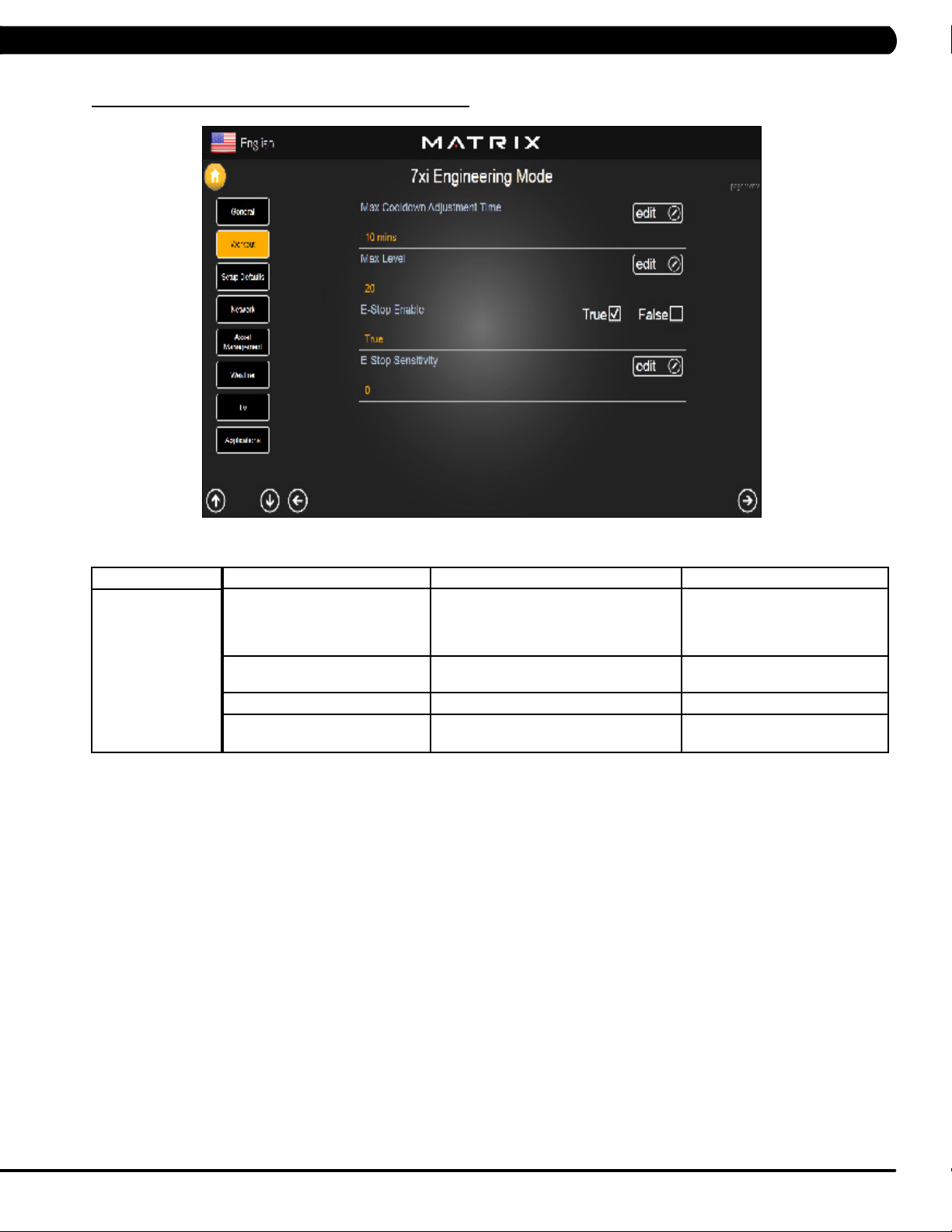
Max Cooldown Adjustment Time This option allows the club to set the
maximum cool down adjustment time
duration limits during peak and non peak
hours.
Max Level This option controls the default program
level.
E-Stop Enable This option controls the E-Stop function TRUE / FALSE
E-Stop Sensitivity This option controls the safety threshold
for the E-Stop function.
Maximum: 20 Minutes
Minimum: 5 Minutes
Maximum: 20 Minutes
Minimum: 1 Minutes
Maximum: 500
Minimum: 4
29
Page 33

CHAPTER 6: ENGINEERING MODE
6.4 ENGINEERING MODE - SETUP DEFAULTS – TAB 1
MANAGER MODE
Setup Defaults
FUNCTION & DEFAULTS DESCRIPTIONS MODIFIED
Level This option allows the club to set the
maximum workout duration limits during
peak and non peak hours.
Age This option controls the default user's age
used in the target heart rate calculations.
Weight This option controls the default weight
used in the calorie calculations. Displayed
in native units (pounds or kilograms).
Gender This option sets the user's gender as
either male or female.
Default Workout Time This option controls the default program
time.
Default Workout Calories This option controls the default program
calories.
Maximum: 20
Minimum: 1
Maximum: 99
Minimum: 10
79~401 lbs
Male or Female
Maximum: 60
Minimum: 5
Maximum: 5000
Minimum: 50
30
Page 34

CHAPTER 6: ENGINEERING MODE
6.4 ENGINEERING MODE - SETUP DEFAULTS – TAB 2
MANAGER MODE
Setup Defaults
6.5 ENGINEERING MODE - NETWORK – TAB 1
FUNCTION & DEFAULTS DESCRIPTIONS MODIFIED
Default Workout Floors This option controls the default program Floors Maximum: 10000
Default Web Brower Page This option controls the default machine Web
Show Sliders In Workout This option controls the default Sliders bar of
Minimum: 10
N/A
Brower Page.
True or False
True or False.
MANAGER MODE
Network
FUNCTION & DEFAULTS DESCRIPTIONS MODIFIED
Wireless Network Setup Wifi setting N/A
31
Page 35

CHAPTER 6: ENGINEERING MODE
6.5 ENGINEERING MODE - NETWORK – TAB 2
MANAGER MODE
Network
6.6 ENGINEERING MODE - ASSET MANAGEMENT
FUNCTION & DEFAULTS DESCRIPTIONS MODIFIED
Wireless or Wired Network Setup Wifi setting N/A
32
MANAGER MODE
Asset Management
FUNCTION & DEFAULTS DESCRIPTIONS MODIFIED
Club ID This option records the club ID of the
fitness facility.
Show Custom Logo This option allows the user to select the
screen Logo from True.
N/A
True or False
Page 36

6.7 ENGINEERING MODE - WEATHER
CHAPTER 6: ENGINEERING MODE
MANAGER MODE
Weather
6.8 ENGINEERING MODE - TV – TAB 1
FUNCTION & DEFAULTS DESCRIPTIONS MODIFIED
Default City This option controls the default City Weather . N/A
Enable Alerts This option controls the City Weather function True or False. True or False
Weather Temperature Unit This option controls how temperature is displayed. Fahrenheit or Celsius
MANAGER MODE
TV
FUNCTION & DEFAULTS DESCRIPTIONS MODIFIED
TV Channel Setup This option is for setting the TV tuner functions. Press the
"Start Scan" to search the TV Channel.
N/A
33
Page 37

6.8 ENGINEERING MODE - TV – TAB 2
CHAPTER 5: ENGINEERING MODE
MANAGER MODE
TV
6.8 ENGINEERING MODE - TV – TAB 3
FUNCTION & DEFAULTS DESCRIPTIONS MODIFIED
Default TV Channel This option controls the default TV channel
on start up.
Maximum: 1000
Minimum: 2
34
MANAGER MODE
TV
FUNCTION & DEFAULTS DESCRIPTIONS MODIFIED
Channel Button Setup This option is for setting the TV channel button.
Press the "Add" to edit the channel icon,
channel name and channel.
N/A
Page 38

CHAPTER 6: ENGINEERING MODE
6.9 ENGINEERING MODE - APPLICATIONS
MANAGER MODE
Applications
FUNCTION & DEFAULTS DESCRIPTIONS MODIFIED
Application Setup This option is for setting the screen table
functions.
N/A
35
Page 39

CHAPTER 6: ENGINEERING MODE
6.10 ENGINEERING MODE - HARDWARE – TAB 1
MANAGER MODE
Hardware
FUNCTION & DEFAULTS DESCRIPTIONS MODIFIED
ErP This option controls the ErP function is
Disabled or Enabled.
ErP Timeout This option controls the console will enter
ErP mode if user does not touch the
screen or press any key pad for couple
minutes.
Backlight Brightness This option controls the screen backlight
Brightness.
LCM test Write test pattern N/A
LCM Version Software version. Cannot be modified.
Play Key Sound This option can set the play workout
countdown to sound or not sound.
Disabled or Enabled
Maximum: 60
Minimum: 1
Low / Medium / High
True or False
36
Page 40
CHAPTER 6: ENGINEERING MODE
6.10 ENGINEERING MODE - HARDWARE – TAB 2
MANAGER MODE
Hardware
6.11 ENGINEERING MODE - SERVICE
FUNCTION & DEFAULTS DESCRIPTIONS MODIFIED
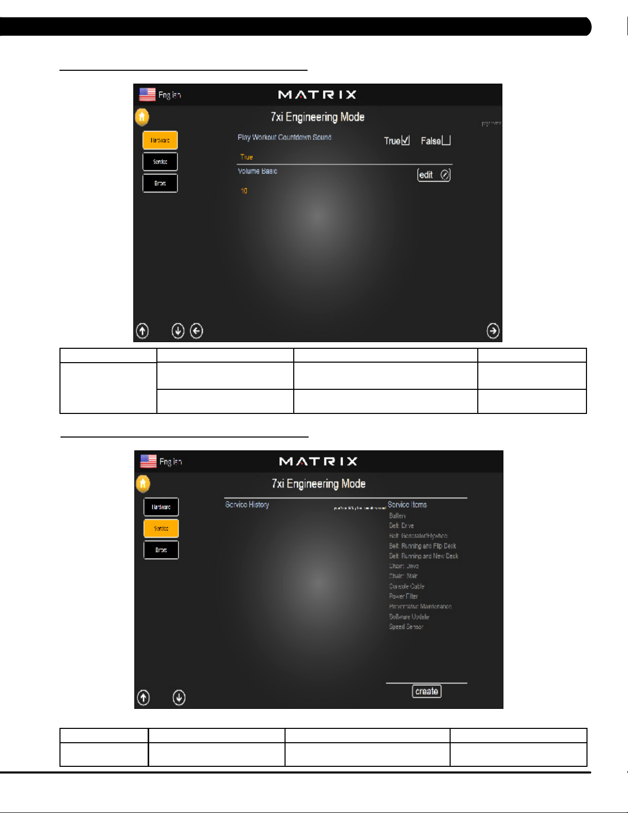
Play Workout Countdown Sound This option can set the play workout countdown
Volume Basic This option controls the default volume on start
to sound or not sound.
up.
True or False
Maximum: 30
Minimum: 0
MANAGER MODE
Service
FUNCTION & DEFAULTS DESCRIPTIONS MODIFIED
Service History This option allows the club to record key
components replacement history.
N/A
37
Page 41

6.12 ENGINEERING MODE - ERRORS
CHAPTER 6: ENGINEERING MODE
MANAGER MODE
Errors
FUNCTION & DEFAULTS DESCRIPTIONS MODIFIED
Error Code History This option displays the error code history on
the treadmill.
N/A
38
Page 42
7.1 USING SERVICE MODE
CHAPTER 7: SERVICE MODE
1) To enter Service Mode, press "ENTER 3, 0, 0, 1, ENTER" on the number keypad and Service Mode will appear on the display.
2) Service Mode is divided into 15 tabs, located on the left side of the screen. They are General, Workout, Setup Defaults, Update, Network,
Asset Management, Weather, TV, Applications, Calibration, Hardware, Virtual Active, Management, Service, Errors.
3) Choose a tab by touching the screen over the desired tab.
4) Each of the tabs has options that will appear once you have chosen that particular tab.
5) Press the "HOME" button or the EMERGENCY STOP to exit Service Mode..
39
Page 43

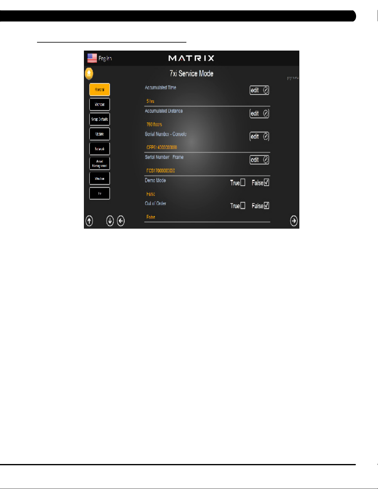
7.2 SERVICE MODE - GENERAL - TAB 1
CHAPTER 7: SERVICE MODE
MANAGER MODE
General
FUNCTION & DEFAULTS DESCRIPTIONS MODIFIED
Accumulated Time Total time on the unit since production. Cannot be modified.
Accumulated Distance Total distance on the unit since production. Cannot be modified.
Serial Number - Console This option displays the serial number of
the console. See Service Mode to edit the
serial numbers.
Serial Number - Frame This option displays the serial number of
the Frame. See Service Mode to edit the
serial numbers.
Demo Mode This option allows the engineer to try and
errors for console
Out of Order This option allows the club to show the unit
"out of order" if an error is present.
Cannot be modified.
Cannot be modified.
True / False
True / False
40
Page 44

SERVICE MODE - GENERAL – TAB 2
7.2
CHAPTER 7: SERVICE MODE
MANAGER MODE
General
SERVICE MODE - GENERAL – TAB 3
7.2
FUNCTION & DEFAULTS DESCRIPTIONS MODIFIED
Date & Time This option sets the current date and time of the machine. N/A
MANAGER MODE
General
FUNCTION & DEFAULTS DESCRIPTIONS MODIFIED
Screen Timeout This option sets the machine show the
workout time of the machine.
Software Versions Software versions. Cannot be modified.
Show Setup Wizard This option can setup machine finish
a certain job fast under not needing
complicated operation.
Maximum: 120 sec
Minimum: 15 sec
True / False
41
Page 45

7.2 SERVICE MODE - GENERAL - TAB 4
CHAPTER 7: SERVICE MODE
MANAGER MODE
General
FUNCTION & DEFAULTS DESCRIPTIONS MODIFIED
Language Setup Sets the language used on the console. English (US), English (UK),
German, French, Italian, Spanish,
Dutch, Portuguese, Korean,
Israeli, Swiss, Russian, Finnish,
Taiwanese, Chinese, or Japanese.
42
Page 46

7.3 SERVICE MODE - WORKOUT – TAB 1
CHAPTER 7: SERVICE MODE
MANAGER MODE
Workout
FUNCTION & DEFAULTS DESCRIPTIONS MODIFIED
Maximum Workout Time This option allows the club to set the
maximum workout duration limits during
peak and non peak hours.
Maximum Workout Calories This option allows the club to set the
maximum workout duration limits during
peak and non peak hours.
Maximum Workout Floors This option allows the club to set the
maximum workout duration limits during
peak and non peak hours.
Pause Time This option controls the default pause time. Max: 10 Minutes
Min Cooldown Time This option allows the club to set the
minimum cool down duration limits during
peak and non peak hours.
Max Cooldown Time This option allows the club to set the
maximum cool down duration limits during
peak and non peak hours.
Maximum: 120 Minutes
Minimum: 10 Minutes
Maximum: 10000
Minimum: 50
Maximum: 10000
Minimum: 10
Minimum: 1 Minutes
Maximum: 5 Minutes
Minimum: 1 Minutes
Maximum: 10 Minutes
Minimum: 5 Minutes
43
Page 47

7.3 SERVICE MODE - WORKOUT – TAB 2
CHAPTER 7: SERVICE MODE
MANAGER MODE
Workout
FUNCTION & DEFAULTS DESCRIPTIONS MODIFIED
Max Cooldown Adjustment Time This option allows the club to set the
maximum cool down adjustment time
duration limits during peak and non peak
hours.
Max Level This option controls the default program
level.
E-Stop Enable This option controls the E-Stop function TRUE / FALSE
E-Stop Sensitivity This option controls the safety threshold
for the E-Stop function.
Maximum: 20 Minutes
Minimum: 5 Minutes
Maximum: 20 Minutes
Minimum: 1 Minutes
Maximum: 500
Minimum: 4
44
Page 48

CHAPTER 7: SERVICE MODE
7.4 SERVICE MODE - SETUP DEFAULTS – TAB 1
MANAGER MODE
Setup Defaults
FUNCTION & DEFAULTS DESCRIPTIONS MODIFIED
Level This option controls the default program
levels.
Age This option controls the default user's age
used in the target heart rate calculations.
Weight This option controls the default weight
used in the calorie calculations. Displayed
in native units (pounds or kilograms).
Gender This option sets the user's gender as
either male or female.
Default Workout Time This option controls the default program
time.
Default Workout Calories This option controls the default program
calories.
Maximum: 20
Minimum: 1
Maximum: 99
Minimum: 10
79~401 lbs
Male or Female
Maximum: 60
Minimum: 5
Maximum: 5000
Minimum: 50
45
Page 49

CHAPTER 7: SERVICE MODE
7.4 SERVICE MODE - SETUP DEFAULTS – TAB 2
MANAGER MODE
Setup Defaults
7.5 SERVICE MODE - UPDATE
Default Workout Floors This option controls the default program
Default Web Brower Page This option controls the default machine Web
Show Sliders In Workout This option controls the default Sliders bar of
FUNCTION & DEFAULTS DESCRIPTIONS MODIFIED
Distance
Brower Page
True or False
Maximum: 10000
Minimum: 10
N/A
True or False
46
MANAGER MODE
Update
FUNCTION & DEFAULTS DESCRIPTIONS MODIFIED
Check For Updates At boot This option will check for update at boot form
the machine.
Automatic Update Software update automatic
N/A
N/A
Page 50

7.6 SERVICE MODE - NETWORK – TAB 1
CHAPTER 7: SERVICE MODE
MANAGER MODE
Network
7.6 SERVICE MODE - NETWORK – TAB 2
FUNCTION & DEFAULTS DESCRIPTIONS MODIFIED
Wireless Network Setup Wifi setting N/A
MANAGER MODE
Network
FUNCTION & DEFAULTS DESCRIPTIONS MODIFIED
Wireless or Wired Network Setup Wifi setting N/A
47
Page 51

CHAPTER 7: SERVICE MODE
7.7 SERVICE MODE - ASSET MANAGEMENT
MANAGER MODE
Asset Management
7.8 SERVICE MODE - WEATHER
FUNCTION & DEFAULTS DESCRIPTIONS MODIFIED
Club ID This option records the club ID of the
Show Custom Logo This option allows the user to select the
fitness facility.
N/A
True or False
screen Logo from True.
48
MANAGER MODE
Weather
FUNCTION & DEFAULTS DESCRIPTIONS MODIFIED
Default City This option controls the default City Weather N/A
Enable Alerts This option controls the City Weather function True or False True or False
Temperature Units This option controls how the temperature is displayed. Fahrenheit or Celsius
Page 52

7.9 SERVICE MODE - TV – TAB 1
CHAPTER 7: SERVICE MODE
MANAGER MODE
TV
7.9 SERVICE MODE - TV – TAB 2
FUNCTION & DEFAULTS DESCRIPTIONS MODIFIED
TV Channel Setup This option is for setting the TV tuner functions. Press the
"Start Scan" to search the TV Channel.
N/A
MANAGER MODE
TV
FUNCTION & DEFAULTS DESCRIPTIONS MODIFIED
Default TV Channel This option controls the default TV channel
on start up.
Maximum: 1000
Minimum: 2
49
Page 53

7.9 SERVICE MODE - TV – TAB 3
CHAPTER 7: SERVICE MODE
MANAGER MODE
TV
7.10 SERVICE MODE - APPLICATIONS
FUNCTION & DEFAULTS DESCRIPTIONS MODIFIED
Channel Button Setup This option is for setting the TV channel button.
Press the "Add" to edit the channel icon,
N/A
channel name and channel.
50
MANAGER MODE
Applications
FUNCTION & DEFAULTS DESCRIPTIONS MODIFIED
Application Setup This option is for setting the screen table
functions.
N/A
Page 54

7.11 SERVICE MODE - HARDWARE – TAB 1
CHAPTER 7: SERVICE MODE
MANAGER MODE
Hardware
FUNCTION & DEFAULTS DESCRIPTIONS MODIFIED
ErP This option controls the ErP function is
Disabled or Enabled.
ErP Timeout Console will enter ErP mode if user does
not touch the screen or press any key pad
for couple minutes.
Backlight Brightness This option controls the screen backlight. Low / Medium / High
LCM test Write test pattern. N/A
LCM Version Software version. Cannot be modified.
Small LCD Reversed This option can set the small LCD to
reversed.
Disabled or Enabled
Maximum: 60
Minimum: 1
True or False
51
Page 55

7.11 SERVICE MODE - HARDWARE – TAB 2
CHAPTER 7: SERVICE MODE
MANAGER MODE
Hardware
FUNCTION & DEFAULTS DESCRIPTIONS MODIFIED
Play Key Sound This option can set the keypad tone to
sound or not sound.
Play Workout Countdown Sound This option can set the play workout
countdown to sound or not sound.
Volume Basic This option controls the default volume on
start up.
Volume Advanced This option controls the default volume on
start up for Master, iPod, Virtual Active,
CSAFE, TV, Media Player
True or False
True or False
Maximum: 30
Minimum: 0
N/A
52
Page 56

7.12 SERVICE MODE - VIRTUAL ACTIVE
CHAPTER 7: SERVICE MODE
MANAGER MODE
Virtual Active
7.13 SERVICE MODE - MANAGEMENT
FUNCTION & DEFAULTS DESCRIPTIONS MODIFIED
Root Path This Virtual Active root path setting D:
MANAGER MODE
Management
FUNCTION & DEFAULTS DESCRIPTIONS MODIFIED
Setting Manager Setting Manager date N/A
53
Page 57

7.14 SERVICE MODE - SERVICE
CHAPTER 7: SERVICE MODE
MANAGER MODE
Service
7.15 SERVICE MODE - ERRORS
FUNCTION & DEFAULTS DESCRIPTIONS MODIFIED
Service History This option allows the club to record key
components replacement history.
N/A
54
MANAGER MODE
Errors
FUNCTION & DEFAULTS DESCRIPTIONS MODIFIED
Error Code History This option displays the error code history on
the treadmill.
N/A
Page 58

7.16 SERVICE MODE - NETPULSE
CHAPTER 7: SERVICE MODE
MANAGER MODE
Netpulse
FUNCTION & DEFAULTS DESCRIPTIONS MODIFIED
Test network and netpulse install. N/A
55
Page 59

CHAPTER 7: SERVICE MODE
7.17 MATRIX FITNESS 7XI SERIES FEATURE ACCESS CODES
This document defines the supported feature access codes for the Matrix Fitness 7xi series fitness equipment.
Instruction
All codes are entered in by:
1. Press the “Enter” key.
2. Press the series of numbers in the code.
3. Press the “Enter” key.
CODE DESCRIPTION
1001
2001
3001
3002
3004
3008
4001
4002
4004
4005
4006
732668
7944357
62728466
287767
999
Enter manager screen.
Enter engineering screen.
Enter service screen
Model selection
Update manager
Enable/disable all errors
Take a screen shot of the current screen
Show/hide the system resources window
Show/hide CSAFE log window
Set factory defaults
Export the error logs to an external USB drive
Reboot
Show help window
Marathon mode
Show/hide cursor
Record workout data to USB drive at summary screen (INTERNAL USE ONLY)
56
Page 60

8.1 ELECTRICAL DIAGRAMS
CHAPTER 8: TROUBLESHOOTING
57
Page 61

CHAPTER 8: TROUBLESHOOTING
8.1 ELECTRICAL DIAGRAMS - CONTINUED
58
Page 62

CHAPTER 8: TROUBLESHOOTING
8.1 ELECTRICAL DIAGRAMS - CONTINUED
P01 - DIGITAL COMMUNICATION WIRE
P13- SPEED SENSOR EXTENSION WIRE
59
Page 63

8.1 ELECTRICAL DIAGRAMS - CONTINUED
P27 - HAND PULSE WIRES
CHAPTER 8: TROUBLESHOOTING
60
Page 64

CHAPTER 8: TROUBLESHOOTING
8.1 ELECTRICAL DIAGRAMS - CONTINUED
P31 - PROXIMITY SENSOR WIRE
P04 - ECB LOAD WIRE
61
Page 65

8.1 ELECTRICAL DIAGRAMS - CONTINUED
P19 - POWER SENSOR WIRE
CHAPTER 8: TROUBLESHOOTING
P18 - CONTROL ZONE SENSOR WIRE
62
Page 66

CHAPTER 8: TROUBLESHOOTING
8.1 ELECTRICAL DIAGRAMS - CONTINUED
G18 - H/P CONNECT WIRE
63
Page 67

8.2 LCB ERROR INDICATORS
CHAPTER 8: TROUBLESHOOTING
64
Page 68

CHAPTER 8: TROUBLESHOOTING
8.2 LCB ERROR INDICATORS - CONTINUED
Status LED
---------------------------------------------------------------------------------Firmware definition-----------------------------------------------------------------------------------
LED STATUS DESCRIPTION
LED1 LCB status (blinking: OK).
LED2 Start or Stop( bright: start )
LED3 Safety stop ( bright: action )
LED4 Safety Key action status ( bright: trigger )
LED5 LCB Error status
LED6 UCB and LCB connection status (blinking: OK)
--------------------------------------------------------------------------------
LED STATUS DESCRIPTION
LED7 MCU power lamp
LED8 Electro-magnet device 2 PWM lamp
LED9 Electro-magnet device 2 fan lamp
LED10 Electro-magnet device 1 PWM lamp
LED11 Electro-magnet device 1 fan lamp
LED12 DC brake release lamp
LED13 DC 26V lamp
D12 Safety switch power lamp
D35 RPM lamp
D8 Positioning sensor lamp
D15 DC 12V lamp
Hardware definition-----------------------------------------------------------------------------------
65
Page 69

CHAPTER 8: TROUBLESHOOTING
8.3 ERROR CODE TROUBLESHOOTING - 01AC
ERROR CODE 01AC
1) SYMPTOM:
a. 01AC - Electro magnet (ECB) over current.
2) SOLUTION:
a. On standby mode, measure the resistance on ECB1 and ECB2. Please check the ECB extension cable connection at the LCB (pins 1 &
3 for ECB1, pins 2 & 4 for ECB2), there should be between 12.8 ~ 14.2 ohms. (Figure A)
- If the ECB resistance is out of the range, replace the ECB.
- If the ECB resistance is within the range, replace the LCB.
b. Check the gap of ECB1 and ECB2. There should be a gap of .5mm between the ECB and the flywheel.
- Adjust the gap as shown in Section 9.16.
FIGURE A
66
Page 70

CHAPTER 8: TROUBLESHOOTING
8.4 ERROR CODE TROUBLESHOOTING - 01AF
ERROR CODE 01AF
1) SYMPTOM:
a. 01AF - Electro magnet (ECB) disconnected.
2) SOLUTION:
a. Check the connection of the ECB extension cable from the LCB to the ECB (Figure A).
b. Check to see if LED8 and LED10 on the LCB have a brief light for 3 second when you power on machine.
- If LED8 and LED10 do not have a brief light, replace the LCB.
- If LED8 and LED10 do have a brief light, check the ECB extension cable connection at the LCB (pins 1 & 3 for ECB1, pins 2 & 4 for
ECB2), there should be between 12.8 ~ 14.2 ohms. (Figure B)
- If the ECB resistance is out of the range, replace the ECB.
- If the ECB resistance is within the range, replace the LCB.
b. Check the gap of ECB1 and ECB2 (Figure B). There should be a gap of .5mm between the ECB and the flywheel.
- Adjust the gap as shown in Section 9.16.
FIGURE A
FIGURE B
67
Page 71

CHAPTER 8: TROUBLESHOOTING
8.5 ERROR CODE TROUBLESHOOTING - 02A0
ERROR CODE 02A0
1) SYMPTOM:
a. 02A0 - Encoder error.
b. The unit is in PAUSE Mode at all times.
2) SOLUTION:
a. Check the connection of the speed sensor cable from the LCB to the speed sensor (Figure A).
b. Check to see if LED D35 on the LCB is on when the brake is turned to the left release position.
If LED D35 is off, move the stairs about 3 stairs and check to see if LED D35 is flashing.
- If not, replace the speed sensor.
- If yes, adjust the speed sensor position and clean the speed sensor of any debris (Figures B), the re-test.
FIGURE BFIGURE A
68
Page 72

CHAPTER 8: TROUBLESHOOTING
8.6 ERROR CODE TROUBLESHOOTING - 02BE / 02BF
ERROR CODE 02BE / 02BF
1) SYMPTOM:
a. 02BE - DC brake error (If movement is detected when the brake is in stop mode).
b. 02BF - DC brake error (The brakes current is over 1A for a continuous 3 sec.).
2) SOLUTION:
a. Check the power extend wire connection between the brake and LCB for any damage (Figures A & B).
b. Check to see if the stairs will move when you are in the stop position. If yes, replace the brake.
FIGURE BFIGURE A
69
Page 73

CHAPTER 8: TROUBLESHOOTING
8.7 ERROR CODE TROUBLESHOOTING - 02CO
ERROR CODE 02C0
1) SYMPTOM:
a. 02C0 - DC brake in manual mode.
2) SOLUTION:
a. Check if the DC brake is in the “ Right “ lock position (Figure A). Release the brake (move to the left) if in lock position.
b. Replace the brake.
FIGURE A
70
Page 74

CHAPTER 8: TROUBLESHOOTING
8.8 ERROR CODE TROUBLESHOOTING - 02C1
ERROR CODE 02C1
1) SYMPTOM:
a. 02C1 -Speed tracking error (the speed tracking is off by at least 10 rpms for a continuous 20 sec).
2) SOLUTION:
a. Adjust the speed sensor position and clean the speed sensor of any debris (Figure A).
b. Check the ECB extension cable connection at the LCB (pins 1 & 3 for ECB1, pins 2 & 4 for ECB2), there should be between 12.8 ~ 14.2
ohms, check which ECB is outside the range and replace it (Figure B).
FIGURE A FIGURE B
71
Page 75

CHAPTER 8: TROUBLESHOOTING
8.9 ERROR CODE TROUBLESHOOTING - 04A0
ERROR CODE 04A0
1) SYMPTOM:
a. 04A0 - UCB has no communication or is disconnected.
2) SOLUTION:
a. Check the console cable connections at the LCB and PCB (Figure A & B).
b. Replace the console cable.
c. Replace the UCB.
FIGURE BFIGURE A
72
Page 76

CHAPTER 8: TROUBLESHOOTING
8.10 ERROR CODE TROUBLESHOOTING - 04B0
ERROR CODES 04B0
1) SYMPTOM:
a. 04B0 - LCB no communication response for over 3 seconds. .
2) SOLUTION:
a. Check the console cable connections at the LCB and PCB (Figure A & B).
b. Replace the console cable.
c. Replace the LCB.
FIGURE A FIGURE B
73
Page 77

CHAPTER 8: TROUBLESHOOTING
8.11 TROUBLESHOOTING - HEART RATE ISSUES
HEART RATE ISSUES
1) SYMPTOM:
a. No heart rate.
b. Erratic or consistently high heart rate.
2) SOLUTION:
a. With a multi-meter set for DC Voltage, place one prong of the multi-meter on each of the heart rate plates on the handlebar (Figure A).
A correctly connected HR grip will have a DC Voltage reading of between .5 and 2.0VAC. Repeat this step on both HR grips. If this reading is
correct, skip to Step b. If not continue with Step a.
- Remove the screws holding the 2 halves of the HR grip together (Figure B).
FIGURE A
- Check the connection of the heart rate grip wiring to the grips (Figure C). Replace the HR grips if any damage is seen to the plates.
- Loosen the 6 handlebar screws on each side of the unit (Figure D).
FIGURE B
FIGURE DFIGURE C
74
Page 78

CHAPTER 8: TROUBLESHOOTING
8.11 TROUBLESHOOTING - HEART RATE ISSUES - CONTINUED
- Remove the 2 screws going into the handlebar connection frame from the bottom (Figure E).
- Remove the 3 screws going into the handlebar connection frame from the top (Figure F).
FIGURE FFIGURE E
- Pull the handlebars out of the handlebar connection frame, and disconnect the HR wiring on each side (Figure G).
- Remove the handlebar connection frame from the unit (Figure H).
FIGURE HFIGURE G
- Perform a continuity test on the wiring going from the HR grip to the handlebar connection frame. With a multi-meter set for ohms,
place one prong on the HR grip wiring coming out of the handlebar (Figure I) and one prong on the HR plate. The HR wiring is red, black, and
white (match red with red and white with white). For example, the red wire on the left HR grip wiring should correspond with the left top plate.
An ohm reading of less than 1 should be expected. If this reading is higher than 1, or if there is not a reading, replace this section of the HR
grip wiring.
- Repeat the previous step with the opposite side HR grip wiring (Figure J).
FIGURE JFIGURE I
75
Page 79

CHAPTER 8: TROUBLESHOOTING
8.11 TROUBLESHOOTING - HEART RATE ISSUES - CONTINUED
- Remove the console and perform a continuity test on the wiring going from the handlebar connection frame to the console. With a
multi-meter set for ohms, place one prong on the HR grip wiring coming out of the console mast (Figure K) and one prong on the wiring that
connects to the handlebar wiring (Figure L - match red with red and white with white). An ohm reading of less than 1 should be expected. If this
reading is higher than 1 or if there is not a reading, replace this section of HR grip wiring.
FIGURE LFIGURE K
b. If your problem is not with the HR grips, a continuity check should be performed on the unit to verify that the console is properly grounded
(see Service Bulletin – Continuity Test on Matrix Climb Mills).
- Once the console grounding has been verified, the heart rate board ground wire should be verified.
- Remove the 6 screws holding the console back to the front (Figure M).
- Check to make sure that the HR board ground wire is plugged into the console ground wire that plugs into the ground wire run down the
console mast. Retest for HR if not properly connected.
- Remove the 2 screws holding the HR board to the console frame.
- With your multi-meter set for ohms, place one prong of your multi meter on the ground wire coming from the HR board (Figure N) and
the other on the console ground wire that comes out of the console and plugs into the ground wire going down the console mast. An ohm
reading of less than 1 should be expected. If this is higher than 1 or if there is not a reading, replace the HR board ground wire.
FIGURE NFIGURE M
76
- If no problems were found using the troubleshooting above, replace the HR board.
- If the HR board does not solve the issue, replace the console.
Page 80

CHAPTER 8: TROUBLESHOOTING
8.12 TROUBLESHOOTING - TOGGLE ISSUES
TOGGLE ISSUES
1) SYMPTOM:
a. No response on the grip toggles
b. The console beeps when the toggles are pressed, but no change on console.
2) SOLUTION:
a. Remove the screws holding the 2 halves of the HR grip together (Figure A).
- Check the connection of the toggle wiring to the toggle keypad (Figure B). note: There should be a red dot on both the toggle
harness and the grip wiring indicating the correct way to plug in the toggles (the red dots should be on the same side of the connector).
FIGURE A FIGURE B
- Place a screwdriver or other metal object between pins 1 & 2 and 2 & 3 on the grip wiring (Figure C). The console should beep when
these wires are bridged. If the console beeps, replace the toggles. If the console does not beep, continue with the steps below.
- Loosen the 6 handlebar screws on each side of the unit (Figure D).
FIGURE DFIGURE C
77
Page 81

CHAPTER 8: TROUBLESHOOTING
8.12 TROUBLESHOOTING - TOGGLE ISSUES - CONTINUED
- Remove the 2 screws going into the handlebar connection frame from the bottom (Figure E).
- Remove the 3 screws going into the handlebar connection frame from the top (Figure F).
FIGURE FFIGURE E
- Pull the handlebars out of the handlebar connection frame, and disconnect the grip wiring on each side (Figure G).
- Remove the handlebar connection frame from the unit (Figure H).
78
FIGURE HFIGURE G
- Perform a continuity test on the wiring going from the toggle to the handlebar connection frame. With a multi-meter set for ohms, place
one prong on the toggle wiring coming out of the handlebar (Figure I) and one prong on the wire on the toggle connector (the toggle wires are
yellow, blue, and green - match similar colors). An ohm reading of less than 1 should be expected. If this reading is higher than 1, or if there is
not a reading, replace this section of the grip wiring.
- Repeat the previous step with the opposite side grip wiring (Figure J).
FIGURE JFIGURE I
Page 82

CHAPTER 8: TROUBLESHOOTING
8.12 TROUBLESHOOTING - TOGGLE ISSUES - CONTINUED
- Remove the console and perform a continuity test on the wiring going from the handlebar connection frame to the console. With
a multi-meter set for ohms, place one prong on the grip wiring coming out of the console mast (Figure K) and one prong on the wiring that
connects to the handlebar wiring (Figure L - match blue with blue, green with green, and yellow with yellow). An ohm reading of less than 1
should be expected. If this reading is higher than 1 or if there is not a reading, replace this section of grip wiring.
FIGURE LFIGURE K
b. If your problem is not with the toggles or toggle wiring, the issue is likely with the console.
79
Page 83

CHAPTER 8: TROUBLESHOOTING
8.13 TV TROUBLESHOOTING - OVERVIEW
Sections8.13-8.16willassistwithdiagnosingproblemswithTVandentertainmentrelatedequipmentsold
byMatrixFItnessEquipment.
The Matrix 7xe console includes an integrated TV that shows in the large display window. The TV is capable of being shown as a 7" or 15"
screen (Figures A & B). The console should be equipped with an entertainment keypad similar to Figure C.
FIGURE A
FIGURE B
FIGURE C
80
Page 84

CHAPTER 8: TROUBLESHOOTING
8.14 TV TROUBLESHOOTING - PICTURE FUZZY OR UNCLEAR
1) For a fuzzy or unclear picture, see the TV programming instructions in Section 10. If the TV is still fuzzy or unclear after programming:
a) Check the coax connection at the entertainment port (Figure A).
b) Remove the 5 screws holding the console to the console mast and check the coax connection at the console (Figure B).
FIGURE A
c) Use a verified good piece of coax cable (a good coax cable will have a signal strength of 10hz or greater) to plug directly into the back
of the console bypassing the entertainment port. If this resolves the issue, replace the internal coax cable.
d) If plugging the coax cable into the back of the console does not resolve the issue, remove the console back and check the console
cable connection at the tuner (Figure C).
e) Check the internal cables and fitting inside your machine at the console and below the front shroud (Figure D). Make sure you have
no kinks, cuts, or poor connectors at the end of the cable. Fittings should have a clean flush connector with no stray aluminum strands touching
the center conductor. Replace any suspect cables.
FIGURE B
FIGURE C FIGURE D
f) If no damage can be found on the cables, fittings, or connectors, and hooking the coax directly to the back of the console does not
resolve the issue, replace the TV tuner.
81
Page 85

CHAPTER 8: TROUBLESHOOTING
8.15 TV TROUBLESHOOTING - TV WILL NOT TURN ON
1) Remove the console back and check the electrical connections for the TV (Figures A & B).
FIGURE BFIGURE A
2) After you have verified that all connects are secure, and the problem still persists, verify power at the outlet (Figure C). If the outlet is not
outputting 120V, check the fitness room power.
3) If internal electrical connections are good, and the outlet is outputting 120V, the issue is likely with the TV. Replace the console.
82
FIGURE C
Page 86

CHAPTER 8: TROUBLESHOOTING
8.16 TV TROUBLESHOOTING - ENTERTAINMENT KEYPAD ISSUES
ENTERTAINMENT KEYPAD IS NOT WORKING
1) SYMPTOM:
a. The entertainment keypad (Figure A) is not responding.
2) SOLUTION:
a. Remove the console and check the connection of the entertainment keypad (Figure B).
b. If the entertainment keypad cable is pinched, kinked, or cut replace the keypad.
c. If replacing the keypad does not resolve the issue, replace the console.
FIGURE A
FIGURE B
83
Page 87
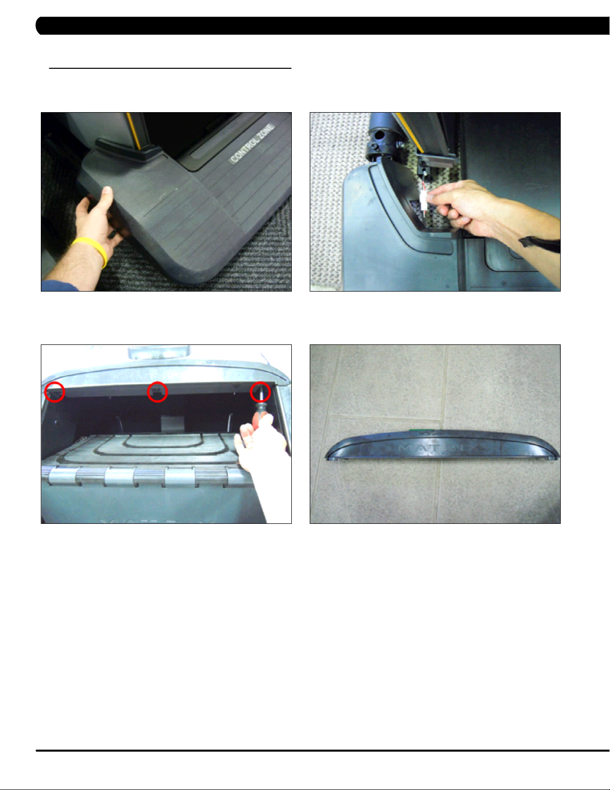
CHAPTER 9: PART REPLACEMENT GUIDE
9.1 SIDE COVER REPLACEMENT
1) Turn off power and disconnect the cord from the machine.
2) Pull up on the Control Zone carefully (Figure A).
3) Unplug the wire connector from the Control Zone and remove the Control Zone from the unit (Figure B).
FIGURE A FIGURE B
4) Remove the 3 screws and remove the small Matrix logo cover at the top of the stairs (Figures C & D).
FIGURE C
FIGURE D
84
Page 88
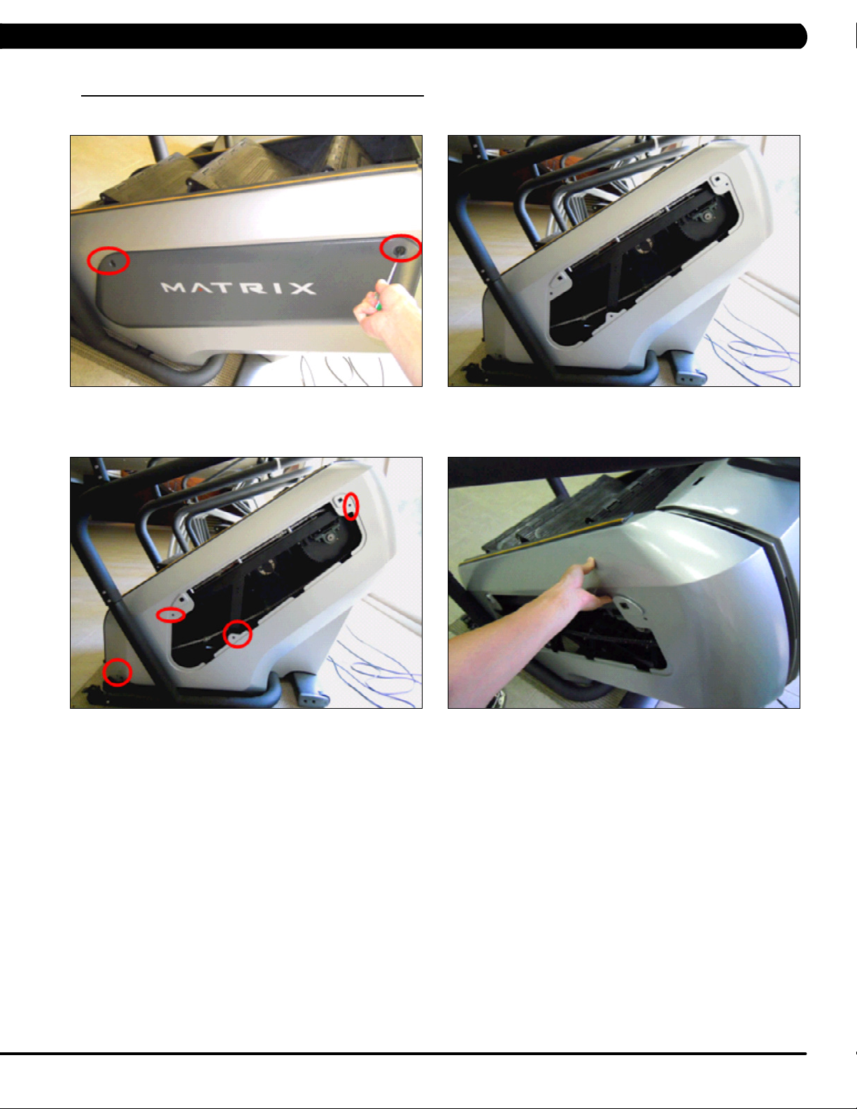
CHAPTER 9: PART REPLACEMENT GUIDE
9.1 SIDE COVER REPLACEMENT - CONTINUED
5) Rotate the 2 plastic clips counter-clockwise to remove the Matrix logo cover (Figures E & F).
FIGURE E
6) Remove the 4 screws holding the side cover to the frame and pull up on the side cover to remove it (Figures G & H).
FIGURE F
FIGURE HFIGURE G
7) Reverse Steps 1-6 to install a new side cover.
85
Page 89

CHAPTER 9: PART REPLACEMENT GUIDE
9.2 CONSOLE REPLACEMENT
1) Turn off power and disconnect the cord from the machine.
2) Remove the 5 screws that hold the console to the console mast (Figure A).
3) Disconnect the console cable and other wiring from the console, then remove the console (Figure B).
FIGURE BFIGURE A
4) Connect the wiring to the new console.
5) Carefully push the wires into the console and console mast until they are clear of the console / mast connection.
6) Attach the console to the console mast using the screws removed in Step 2.
7) Test the Climb Mill for function as outlined in Section 9.20.
86
Page 90

CHAPTER 9: PART REPLACEMENT GUIDE
9.3 CONSOLE KEYPAD / OVERLAY REPLACEMENT
note: The instructions below are for console overlays / keypads replacement, but the procedure is the same regardless of where the overlay /
keypad is.
1) Remove the console as outlined in Section 9.2.
2) Remove the back cover of the console (Figure A).
3) Unplug and remove the faulty overlay (Figure B).
FIGURE A
4) Clean the console area with alcohol to remove any left over adhesive (Figure C).
5) Peel part of the protective film from the back of the overlay / keypad (Figure D).
FIGURE C FIGURE D
FIGURE B
87
Page 91

CHAPTER 9: PART REPLACEMENT GUIDE
9.3 CONSOLE KEYPAD / OVERLAY REPLACEMENT - CONTINUED
6) Push the overlay / keypad ribbon cable through the hole in the console and plug it in (Figure E).
7) Match the overlay / keypad to the cutout in the console (Figure F).
FIGURE E FIGURE F
8) Press down on the corners of the overlay / keypad to keep it in place. Then remove the protective film (Figure G).
9) Once the overlay / keypad is in the correct position, press down on it to adhere it in positions (Figure H).
FIGURE G FIGURE H
10) Use the same procedure to replace any additional faulty overlays / keypads. note: Overlays / keypads cannot be re-used.
11) Test the Climb Mill for function as outlined in Section 9.20.
88
Page 92

CHAPTER 9: PART REPLACEMENT GUIDE
9.4 FRONT SHROUD REPLACEMENT
1) Turn off power and disconnect the cord from the machine.
2) Remove all of the cables from the front cover (Figure A).
3) Remove the 2 screws from the front cover and remove it (Figure B).
FIGURE A
4) Remove both side covers as outlined in Section 9.1.
5) Remove the console as outlined in Section 9.2.
6) Remove the 3 screws on each side that connect the front shroud to the frame (Figure C).
7) Remove the 5 screws that hold the upper handlebar set to the console mast (Figure D).
FIGURE C
FIGURE B
FIGURE D
89
Page 93

CHAPTER 9: PART REPLACEMENT GUIDE
9.4 FRONT SHROUD REPLACEMENT - CONTINUED
8) Disconnect the hand pulse and quick key cables on the inside of the console mast (Figure E).
9) Remove the 8 screws holding the lower handlebar set to the console mast (Figure F).
FIGURE E
10) Remove the 4 screws that attach the console mast to the frame (Figure G).
11) Pull the cables out of the console mast and remove it (Figure H).
FIGURE G
12) Remove the 4 screws holding the front shroud to the sides (Figure I).
13) Pull up on the front shroud and remove it (Figure J).
FIGURE F
FIGURE H
90
FIGURE JFIGURE I
14) Reverse Steps 1-13 to install a new front shroud.
15) Test the Climb Mill for function as outlined in Section 9.20.
Page 94

CHAPTER 9: PART REPLACEMENT GUIDE
9.5 LOWER CONTROL BOARD (LCB) REPLACEMENT
1) Turn off power and disconnect the cord from the machine.
2) Remove all wiring from the front cover and remove it from the machine as outlined in Section 9.4.
3) Disconnect all wiring from the LCB (Figure A).
4) Remove the 2 screws holding the LCB to the frame and remove the LCB (Figure B).
FIGURE A FIGURE B
5) Remove the 2 screws that hold the fan to the LCB and remove it (Figure C).
FIGURE C
6) Reverse Steps 1-5 to install a new LCB.
7) Test the Climb Mill for function as outlined in Section 9.20.
91
Page 95

CHAPTER 9: PART REPLACEMENT GUIDE
9.6 UPPER HANDLEBAR REPLACEMENT
1) Turn off power and disconnect the cord from the machine.
2) Remove the 5 screws holding the upper handlebar set to the console mast (Figure A).
3) Pull out the right handlebar and hand grip cable (Figure B).
FIGURE A FIGURE B
4) Disconnect the wiring that connects the left hand grip cable to the hand pulse extension wire (Figure C).
5) Pull out the left handlebar and hand grip cable (Figure D).
FIGURE D FIGURE C
92
Page 96

CHAPTER 9: PART REPLACEMENT GUIDE
9.6 UPPER HANDLEBAR REPLACEMENT SET - CONTINUED
6) Disconnect the wire that connects the left hand grip cable to the hand pulse extension wire (Figure E).
7) Remove the 2 screws on each side holding the front of the upper handlebar set to the lower handlebar set (Figure F).
FIGURE E
8) Remove the 2 screws on each side holding the rear of the upper handlebar set to the lower handlebar set (Figure G).
FIGURE F
FIGURE G
9) Reverse Steps 1-8 to install a new upper handlebar set.
10) Test the Climb Mill for function as outlined in Section 9.20.
93
Page 97

CHAPTER 9: PART REPLACEMENT GUIDE
9.7 LOWER HANDLEBAR SET REPLACEMENT
1) Turn off the power and disconnect the cord from the machine.
2) Remove the upper handlebar set as outlined in Section 9.6.
3) Remove the 8 screws holding the lower handlebar set to the console mast (Figure A).
4) Remove the 2 screws holding the lower handlebar set to the frame handlebar set, then remove the lower handlebar (Figure B).
FIGURE A FIGURE B
5) Reverse Steps 1-4 to install a new lower handlebar set.
6) Test the Climb Mill for function as outlined in Section 9.20.
94
Page 98

CHAPTER 9: PART REPLACEMENT GUIDE
9.8 HANDLEBAR SERVICE
1) Turn off the power and disconnect the cord from the machine.
2) All items on the handlebar are removed using a Phillips screwdriver from the underside of the bar.
3) Once the screws are removed, lift the part carefully then disconnect any wire connections to fully remove the part. This includes any
resistance, pause / stop buttons, and the heart rate grip plates (Figures A & B).
FIGURE A
4) Test the Climb Mill for function as outlined in Section 9.20.
FIGURE B
95
Page 99

CHAPTER 9: PART REPLACEMENT GUIDE
9.9 STAIR REPLACEMENT
1) Turn off power and disconnect the cord from the machine.
2) Remove the side covers as outlined in Section 9.1.
3) Remove the front shroud as outlined in Section 9.4.
4) Turn the brake bar to the right to lock the stairs in place (Figure A).
5) Remove the X shaped clip from the long axle on the upper side of the stair needing to be replaced (Figure B).
FIGURE A FIGURE B
6) Pull out the axle from the opposite side that you removed the X shaped clip from (Figure C). note: 1. Pay attention to the order of the parts
sequence on the axle as you remove it (Figure D). The correct parts sequence is X shaped clip > bearing > washer > chain > spacer > stair. 2.
Do not reuse the X-washer retainers. Order replacements with your stair or bearing order.
FIGURE C
FIGURE D
96
Page 100

CHAPTER 9: PART REPLACEMENT GUIDE
9.9 STAIR REPLACEMENT - CONTINUED
7) Remove the axle from the lower side of the stairs needing to be replaced following the same procedure as Steps 4-6.
8) Remove the stair set when you have removed both axles (Figure E).
9) Remove the E-shaped clip from the short axle between the 2 portions of the stair set (Figure F). This will allow you to separate the 2 portions
of the stair set.
FIGURE FFIGURE E
10) Reverse Steps 1-9 to install a new stair set.
11) Turn the brake bar to the left to unlock the stairs once the replacement is nished.
12) Test the Climb Mill for function as outlined in Section 9.20.
97
 Loading...