

Page 1

C7XE-05 CLIMB MILL
SERVICE MANUAL
Page 2

III
CHAPTER 1: SERIAL NUMBER LOCATION ........................................................... 1
CHAPTER 2: IMPORTANT SAFETY INSTRUCTIONS
2.1 Read and Save These Instructions ............................................................................. 3
2.2 Electrical Requirements ............................................................................................. 4
2.3 Locating the Unit ......................................................................................................... 5
CHAPTER 3: PREVENTATIVE MAINTENANCE
3.1 Recommended Cleaning Tips .................................................................................... 6
3.2 Care and Maintenance Instructions ........................................................................... 7
3.3 Touchscreen Care & Cleaning .................................................................................... 8
CHAPTER 4: CONSOLE OVERLAY AND WORKOUT DESCRIPTION
4.1 Console Description ................................................................................................... 9
4.2 Workout Setup Steps ................................................................................................. 10
CHAPTER 5: MANAGER MODE
5.1 Manager Mode Overview ............................................................................................ 11
5.2 Manager Mode - About Tab......................................................................................... 12
5.3 Manager Mode - Time Tab .......................................................................................... 13
5.4 Manager Mode - Climb Mill Tab .................................................................................. 13
5.5 Manager Mode - Defaults Tab..................................................................................... 14
5.6 Manager Mode - TV Tab ............................................................................................. 15
5.7 Manager Mode - Language Tab .................................................................................. 16
5.8 Manager Mode - Other Tab ......................................................................................... 16
CHAPTER 6: ENGINEERING MODE
6.1 Engineering Mode Overview ....................................................................................... 17
6.2 Engineering Mode - Calibration Tab............................................................................ 18
6.3 Engineering Mode - Statistics Tab .............................................................................. 18
6.4 Engineering Mode - Errors Tab ................................................................................... 19
6.5 Engineering Mode - Clubs Tab.................................................................................... 19
6.6 Engineering Mode - Club ID Tab ................................................................................. 20
6.7 Engineering Mode - Climb Mill Tab ............................................................................. 20
6.8 Engineering Mode - Other Tab .................................................................................... 21
CHAPTER 7: SERVICE MODE
7.1 Service Mode Overview .............................................................................................. 22
7.2 Service Mode - Setup Tab........................................................................................... 23
7.3 Service Mode - Test Tab ............................................................................................. 24
7.4 Service Mode - Log Tab .............................................................................................. 25
7.5 Service Mode - Date & Time Tab ................................................................................ 25
CHAPTER 8: TROUBLESHOOTING
8.1 Electrical Diagram ...................................................................................................... 26
8.2 LCB Error Indicators .................................................................................................. 33
8.3 Error Code Troubleshooting - 01AC ........................................................................... 35
8.4 Error Code Troubleshooting - 01AF ............................................................................ 36
8.5 Error Code Troubleshooting - 02A0 ........................................................................... 37
8.6 Error Code Troubleshooting - 02BE / 02BF ................................................................ 38
8.7 Error Code Troubleshooting - 02C0 ............................................................................ 39
8.8 Error Code Troubleshooting - 02C1 ............................................................................ 40
8.9 Error Code Troubleshooting - 02C2 ............................................................................ 41
8.10 Error Code Troubleshooting - 02C3 ............................................................................ 42
8.11 Troubleshooting - Error 03A5 / 03A6 .......................................................................... 43
8.12 Troubleshooting - Error 03A7 ...................................................................................... 44
8.13 Troubleshooting - Error 03A8 ...................................................................................... 45
8.14 Error Code Troubleshooting - 04A0 ............................................................................ 46
8.15 Error Code Troubleshooting - 04B0 ............................................................................ 47
8.16 Troubleshooting - No Power to the Console ............................................................... 48
8.17 Troubleshooting - Heart Rate Issues .......................................................................... 49
8.18 Troubleshooting - Toggle Issues ................................................................................. 52
8.19 TV Troubleshooting - Overview ................................................................................... 55
8.20 TV Troubleshooting - Picture Fuzzy or Unclear .......................................................... 56
8.21 TV Troubleshooting - TV Will Not Turn On ................................................................. 57
8.22 TV Troubleshooting - Entertainment Keypad Issues .................................................. 58
CHAPTER 9: PART REPLACEMENT GUIDE
9.1 Side Cover Replacement ........................................................................................... 59
9.2 Console Replacement ................................................................................................. 61
9.3 Console Overlay / Keypad Replacement .................................................................... 62
9.4 Front Shroud Replacement ......................................................................................... 64
9.5 Lower Control Board (LCB) Replacement .................................................................. 66
9.6 Upper Handlebar Replacement .................................................................................. 67
9.7 Lower Handlebar Replacement .................................................................................. 69
9.8 Handlebar Service ....................................................................................................... 70
9.9 Stair Replacement ....................................................................................................... 71
9.10 Drive Set Replacement ............................................................................................... 73
9.11 Chain Replacement ..................................................................................................... 75
9.12 Brake Replacement ..................................................................................................... 77
9.13 Fan Replacement ........................................................................................................ 78
9.14 ECB Belt Replacement ............................................................................................... 79
9.15 Drive Belt Replacement .............................................................................................. 80
9.16 ECB Replacement ....................................................................................................... 81
9.17 Speed Sensor Replacement ....................................................................................... 83
9.18 Control Zone Replacement ......................................................................................... 84
9.19 Proximity Sensor Replacement ................................................................................... 85
9.20 IR Sensor Replacement .............................................................................................. 86
9.21 Testing the Climb Mill .................................................................................................. 88
CHAPTER 10: CLIMB MILL SPECIFICATIONS AND ASSEMBLY GUIDE
10.1 Climb Mill Specifications ............................................................................................ 89
10.2 Assembly Hardware .................................................................................................... 90
10.3 Climb Mill Assembly Steps ......................................................................................... 91
10.4 Stabilizing the Climb Mill ............................................................................................. 95
10.5 TV Programming Instructions ..................................................................................... 96
CHAPTER 11: SOFTWARE UPGRADE PROCEDURE
11.1 Software Upgrade Procedure for UCB ....................................................................... 101
11.2 Software Upgrade Procedure for LCB ........................................................................ 102
TABLE OF CONTENTS TABLE OF CONTENTS
Page 3
1.1 SERIAL NUMBER LOCATION
CHAPTER 1: SERIAL NUMBER LOCATION
SERIAL NUMBER LOCATION
1
Page 4
3
2
console serial number location
1.1 SERIAL NUMBER LOCATION - CONTINUED
CONSOLE SERIAL NUMBER LOCATION
CHAPTER 1: SERIAL NUMBER LOCATION
This Climb Mill is intended for commercial use. To ensure your safety
and protect the equipment, read all instructions before operating the
MATRIX Climb Mill.
When using an electrical product, basic precautions should always be
followed including the following:
• Anapplianceshouldneverbeleftunattendedwhen plugged
in. Unplugtheunitfromtheoutlet whennotinuseandbefore
puttingonortakingoffanyparts.
• Thisproductmustbeusedforitsintended purpose
describedinthisservicemanual. Donot useother
attachmentsthatarenotrecommendbythe manufacturer.
Attachmentsmaycauseinjury.
• Topreventelectricalshock,neverdroporinsertanyobject
intoanyopening.
• Donotremovethesidecovers.Serviceshouldonly bedone
byanauthorizedservicetechnician.
• Neveroperatetheunitwiththeairopeningblocked.Keep
theairopeningclean,freeoflint andhair.
• Neveroperatetheunitifithas adamagedcordorplug,if it
isnotworkingproperly,if ithasbeendamaged,orimmersed
inwater.
• Closesupervisionisnecessarywhentheunitis usedbyor
nearchildrenordisablepersons.
• Donotuseoutdoors.
• Donotoperatewhereaerosol(spray)productsarebeing
usedorwhenoxygenisbeingadministered.
• Donotusetheequipmentinanywayotherthan designedor
intendedbythemanufacturer.Itisimperativethatall Matrix
FitnessSystemsequipmentisusedproperlyto avoidinjury.
• Keephandsandfeetclearofmoving partsatalltimesto
avoidinjury.
• Unsupervisedchildrenmustbekeptawayfrom thisequip
ment.
• Donotwearlooseclothingwhileon theequipment.
*AtNOtimeshouldpets orchildrenundertheageof 14be
closertotheunitthan10feet.
* AtNOtimeshouldchildrenunderthe ageof14usetheunit.
* Childrenovertheageof14or disabledpersonsshouldnot
usetheunit withoutadultsupervision.
* Neveroperatetheunitifithas adamagedcordorplug,if it
isnotworking properly,ifithasbeendroppedor damaged,or
immersedinwater.Returnthe unittoaservicecenterfor
examinationandrepair.
* Todisconnect,turnallcontrolstotheoffposition, then
removeplugfrom outlet.
* Donotremovetheconsolecoversunless instructedby
CustomerTechSupport.Service shouldonlybedonebyan
authorizedservicetechnician.
* Thisunitisnotequippedwitha freewheel.Stepspeed
shouldbe reducedinacontrolledmanner.
* Heartratemonitoringsystemsmaybeinaccurate.
* Overexercisingmayresultinseriousinjury ordeath.
* Ifyoufeelfaint,stopexercisingimmediately.
CAUTION! Ifyouexperiencechestpains, nausea,dizziness,or
shortnessofbreath,stopexercisingimmediatelyand consult
yourphysicianbeforecontinuing.
CAUTION! Anychangesormodificationstothis equipment
couldvoidtheproductwarranty.
2.1 READ AND SAVE THESE INSTRUCTIONS
CHAPTER 2: IMPORTANT SAFETY INSTRUCTIONS
Page 5
5
4
2.2 ELECTRICAL REQUIREMENTS
CHAPTER 2: IMPORTANT SAFETY INSTRUCTIONS
2.3 LOCATING THE UNIT
CHAPTER 2: IMPORTANT SAFETY INSTRUCTIONS
DEDICATED CIRCUIT AND ELECTRICAL INFO
A “Dedicated Circuit” means that each outlet you plug into should not have anything else running on that same circuit. The easiest way to verify
this is to locate the main circuit breaker box, and turn off the breaker(s) one at a time. Once a breaker has been turned off, the only thing that
should not have power to it are the units in question. No lamps, vending machines, fans, sound systems, or any other item should lose power
when you perform this test.
Non-looped (isolated) neutral/grounding means that each circuit must have an individual neutral/ground connection coming from it, and
terminating at an approved earth ground. You cannot “jumper” a single neutral/ground from one circuit to the next.
ELECTRICAL REQUIREMENTS
For your safety and to ensure good unit performance, the ground on this circuit must be non-looped (isolated). Please refer to NEC article 21021 and 210-23. Any alterations to the standard power cord provided could void all warranties of this product.
The 3x, 5x and 7xe
Climbmills are designed to be self-powered and do not require an external power supply source to operate. Without an
external power supply, the console’s start-up time may be delayed. Add-on TV’s and other console accessories will increase the time needed
for start-up. An external power supply will ensure power is provided to the console at all times and is recommended when add-on accessories
are used.
For units with an integrated TV (like the 7xe and 7xi), the TV power requirements are included in the unit. An RG6 coaxial cable with ‘F Type’
compression fittings on each end will need to be connected to the cardio unit and the video source. Additional power requirements are not
needed for the add-on digital TV (3x and 5x). For units with an add-on PCTV (3x and 5x), the TV power requirements are separate.
NOTE: ALL UNITS WITH VIRTUAL ACTIVE™ MUST BE POWERED!
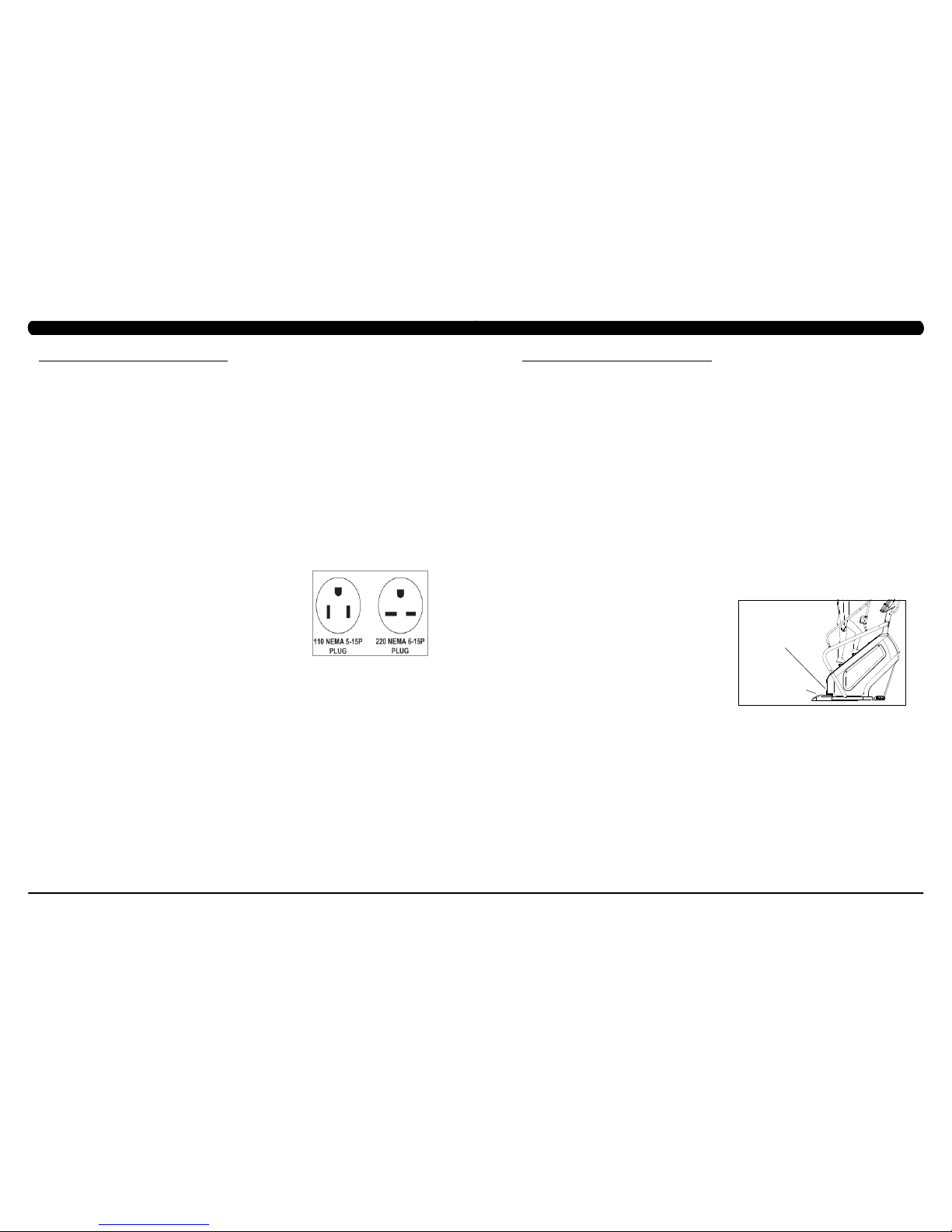
110 V UNITS
All Matrix 3x, 5x, 7xe and 7xi 110 V Climbmills require the use of a 100-125 V, 60 Hz and a 15 A
“Dedicated Circuit”, with a non-looped (isolated) neutral/ground for power. This outlet should be a
NEMA 5-15R and have the same configuration as the plug. No adapter should be used with this
product. These bikes can be daisy-chained together with up to 4 units per 15 A dedicated circuit.
Matrix daisy-chain cord adapters are sold separately.
220 V UNITS
All Matrix 3x, 5x, 7xe and 7xi 220 V Climbmills require the use of a 216-250 V, 50 Hz and a 15 A
“Dedicated Circuit”, with a non-looped (isolated) neutral/ground for power. This outlet should be a
NEMA 6-15R and have the same configuration as the plug. No adapter should be used with this
product. These bikes can be daisy-chained together with up to 4 units per 15 A dedicated circuit.
Matrix daisy-chain cord adapters are sold separately.
North American power cord plugs shown.
Depending on your country, the plug type may vary.
GROUNDING INSTRUCTIONS
The unit must be grounded. If it should malfunction or breakdown, grounding provides a path of least resistance for electric current to reduce
the risk of electric shock. The unit is equipped with a cord having an equipment-grounding conductor and a grounding plug. The plug must be
plugged into an appropriate outlet that is properly installed and grounded in accordance with all local codes and ordinances. If the user does
not follow these grounding instructions, the user could void the Matrix limited warranty.
ADDITIONAL ELECTRICAL INFO
In addition to the dedicated circuit requirement, the proper gauge wire must be used from the circuit breaker box, to each outlet that will have
the maximum number of units running off of it. If the distance from the circuit breaker box to each outlet, is 100 ft (30.5 m) or less, then 12
gauge wire should be used. For distances greater than 100 ft (30.5 m) from the circuit breaker box to the outlet, a 10 gauge wire should be
used.
ENERGY SAVING / LOW-POW ER MODE
All units are configured with the ability to enter into an energy saving / low-power mode when the unit has not been in use for a specified period
of time. Additional time may be required to fully reactivate this unit once it has entered the low-power mode. This energy saving feature may be
enabled or disabled from within the ‘Manager Mode’ or ‘Engineering Mode.
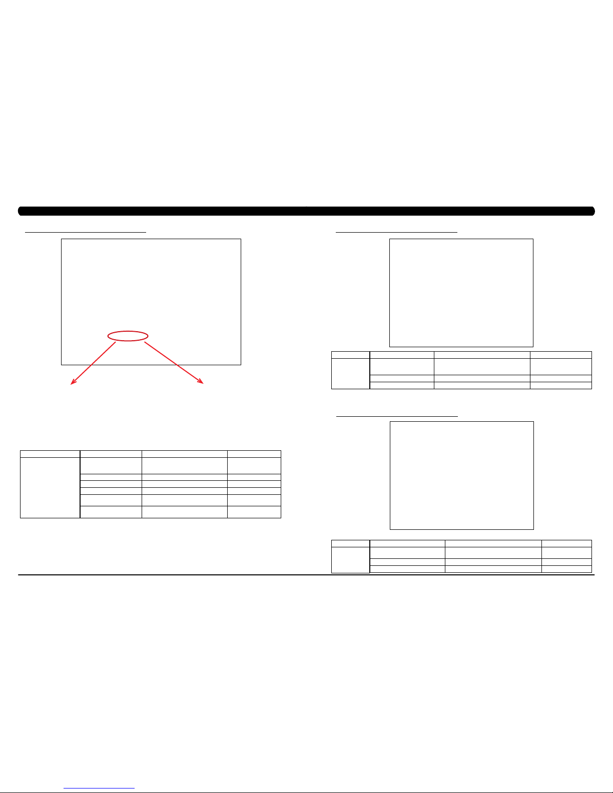
LOCATION OF THE UNIT
Place the unit on a level surface and away from direct sun light. The intense UV light can cause discoloration of plastics. Locate in an area
with cool temperatures and low humidity. Leave a clear zone behind the unit of at least 24". This zone must be clear of any obstruction and
allow the user a clear exit path from the unit. Do not place the unit in any area that will block the openings or vents. The unit should not be
used in a garage or covered patio.
LEVELING THE UNIT
Locate a level, stable surface to position the equipment. The equipment has levelers located below the bottom step. To access the levelers,
remove the end caps (C3X) or CONTROL ZONE (C5X, C7XE and C7XI). CAUTION: There is an electrical plug located under the CONTROL
ZONE and will need to be unplugged before the cover can be completely removed. Use an allen wrench to level the unit. Once stable, replace
parts as they were removed.
HEIGHT REQUIREMENTS
The Climb Mill adds 30" - 38" (76 - 96cm) to a user's height. For example, a 6' (183cm) tall user will be 7'8" (234.4cm - 254.4cm) off the floor.
Total height of the user on the Climb Mill should not exceed 9'10" (300 cm), which means that users taller than 6'8" (204cm) should not use this
equipment.
AUTO STOP
SENSOR
CONTROL ZONE
(C5X, C7XE, C7XI)
Page 6

7
6
3.1 RECOMMENDED CLEANING TIPS
CHAPTER 3: PREVENTATIVE MAINTENANCE
3.2 CARE AND MAINTENANCE INSTRUCTION
CHAPTER 3: PREVENTATIVE MAINTENANCE
FIGURE A
FIGURE A
FIGURE B
FIGURE B
In order to maximize life span, and minimize down time, all Matrix Fitness Equipment requires regularly
scheduled cleaning.
YOU WILL NEED:
- Mild dish soap and water mixture in a spray bottle (10:1 water to soap ratio).
- Lint free 100% cotton cleaning cloths or Micro fiber cleaning cloths.
- Vacuum / Shop Vac with extendable hose and soft brush attachment.
- iPod corrosion blocker - Available from Matrix (part # ZMS4001374).
- Super Lube Multi Purpose Synthetic Lubricant with Syncolon® (PTFE) Aerosol - www.super-lube.com/sythetic-aerosol-spray-ezp-46.html.
- Corrosion Block (available from Matrix - part # ZMS4001374).
- LCD / LED or computer screen cleaner.
DAILY or as needed:
1. Empty the dust tray under the stairs and under the unit (Figure A). If you need to move the unit, unplug it first.
WEEKLY:
1. With a clean dry 100% lint free cloth and water / soap mixture, wipe down the entire frame including the stairs so it is free of dust, dirt, and
sweat.
2. With a clean dry 100% lint free cloth and water / soap mixture, wipe down the entire console area including the hand grips and hand rails.
MONTHLY:
1. Vacuum under and around the Climb Mill If you need to move the unit, unplug it first. Make sure to reset the casters after moving the unit
back into position to stabilize the unit.
2. Apply corrosion block to the metal part of the iPod cable.
3. Use a computer screen cleaner or LCD / LED screen cleaner on the touch screen portion of the console (see Section 3.3).
QUARTERLY:
1. Remove the side access panels and vacuum out the inside of the unit (Figure B).
2. Unplug the Climbmill and clean the AUTO STOP SENSORS (located under the bottom step) / Control Zone sensor with a cotton swab and
rubbing alcohol.
In order to maximize life span, and minimize down time, all MATRIX equipment requires regular cleaning, and maintenance items performed on
a scheduled basis. This section contains detailed instructions on how to perform these items, the frequency of which they should be done, and a
check list to sign off each time service is completed for a specific machine. Some basic tools and supplies will be necessary to perform these tasks
which include (but may not be limited to):
* Metric Allen wrenches
* #2 Phillips head screwdriver
* Adjustable wrench
* Teflon based spray lubricant such as “Super Lube”, or other Matrix approved product
You may periodically see addendums to this document, as the Matrix Technical Support Team identifies items that require specific attention, the
latest version will always be available on the Matrix website, www.matrixfitness.com
DAILY MAINTENANCE ITEMS
1. Attempt to wobble the unit from side to side and front to back. Level the unit if needed (See Section 10.4).
QUARTERLY MAINTENANCE ITEMS
1. Check all connecting joint areas for tightness of fastened assemblies.
2. Remove the maintenance cover and check the fans for function. Also clean and remove any debris from the digital speed sensor.
3. Remove the maintenance cover and check the chains for damage, alignment and proper tension.
4. On units with a Control Zone, check to ensure the CZ is working properly by walking on the unit, then stepping on the CZ. The unit should stop
similar to an emergency stop on a treadmill.
5. Unplug the Climbmill and clean the AUTO STOP SENSORS (located under the bottom step) / Control Zone sensor with a cotton swab and
rubbing alcohol.
6. For 7xe consoles, enter service mode and select ‘test’. Select ‘touch calibration’and then select ‘start’. Follow the on-screen prompts and touch
the screen where indicated.
AUTO STOP
SENSORS
Page 7

9
8
3.3 TOUCH SCREEN CARE & CLEANING
CHAPTER 3: PREVENTATIVE MAINTENANCE
4.1 CONSOLE DESCRIPTION
CHAPTER 4: CONSOLE OVERLAY AND WORKOUT DESCRIPTION
The C7xe has a fully integrated touch screen display. All information required for workouts is explained on screen. Exploration of the interface is
highly encouraged. The information explaining how to program for various workouts will give an explanation about the contents of each screen.
Go: One touch Start.
stoP: Ends workout and shows workout summary data.
cool DoWn
(displayed on-screen during workout): Puts unit into Cool Down mode. Cool Down time is dependent on the length of the workout.
Workouts 19 minutes and shorter will have a cool down length of 2 minutes. Workouts 20 minutes and longer will have a cool down length of 5
minutes.
C7XE ENTERTAINMENT ZONE
iPOD®: Will take the user directly to the iPod screen to allow for iPod control and play list selection.
Volume uP / DoWn: Adjusts the volume output through the headphone jack of the integrated console TV or iPod output.
NUMBERKEYPAD: Allows for easy TV channel selections.
cHannel uP / DoWn: Allows for channel selection.
DISPLAYMODE: Allows user to cycle through console display options, iPod, TV, or profile display.
last cHannel: Allows the user to cycle between the current channel and the previous channel viewed.
cc/mute:
Mutes sound and turns closed captioning on or off.
TOUCH SCREEN CARE AND CLEANING
* The touch screen requires very little maintenance. We recommend that you periodically clean the touch screen surface with a clean dry 100%
lint free cloth and water / soap mixture or a computer or LCD / LED screen cleaner.
* It is very important to avoid using any other chemical on the touch screen.
* Always dampen the cloth and clean the screen. Do not spray the water / soap mixture on the screen itself, the drips can seep into the display
or stain the bezel.
* After cleaning, make sure the surface is dry. There should not be any left over solvent to seep into the display.
* It is very important to handle the touch screen with care. Do not use excessive force when cleaning.
* Do not use any sharp materials to clean the touch screen surfaces.
* Do not use high pressure air, water, or steam to clean the touch screen surface.
Page 8
11
10
To set up a workout, press the touch screen over the program you would
like to use and then follow the prompts to begin your workout.
Go - Press to immediately begin a workout. Workout, resistance level,
and time will automatically go to default settings. All energy expenditure
values will be calculated using the default weight measurement.
manual - Manual allows the user to input more information while
defining their own workout. Calorie expenditure will be more accurate
when inputting information in Manual than by pressing GO.
rollinG Hills - The Rolling Hills program is a level based
program that automatically adjusts the resistance level to simulate real
terrain.
interVals - The Intervals program is a level based program that
automatically adjusts the resistance of the machine from low to high
intensity settings at regular intervals to burn calories.
Goal traininG - The Goal Training program is designed to help
users burn a target number of calories.
calorie traininG - The Calorie Training program is designed
to help users burn a target number of calories.
constant Watts - The Constant Watts program allows
you to vary your cadence or SPM and the machine's resistance will
adjust according to your selected goal. The quicker you step, the less
resistance for the goal selected.
Fat burn - The Fat Burn program is a level based workout that is
designed to help users burn fat through various resistance changes.
tarGet Heart rate - The Matrix Climb Mill comes with
standard digital contact heart rate sensors and are POLAR telemetry
compatible. The heart rate control workout mode allows the user
to program their desired heart rate zone, and the Climb Mill will
automatically adjust the level based upon the user's heart rate. The
heart rate zone is calculated using the following equation: (220-Age)*% =
target heart rate zone. The user must wear a POLAR telemetric strap or
continually hold onto the contact heart rate grips for this workout.
Locate the metal sensors on the handlebars of the Climb Mill. Notice
that there are two separate pieces of metal on each grip. You must be
making contact with both pieces of each grip to get an accurate heart
rate reading. You can grab these sensors in any program to view your
current heart rate.
FITNESSTEST(WFI) - The WFI (Wellness Fitness Initiative)
protocol is a test used by firefighters in a series of intervals lasting a
maximum of 16 minutes, where the speed is increased every minute
until the Target Heart Rate is exceeded for 15 seconds. When the
test is complete, the display provides a summary of V)2max, Highest
SPM, Elapsed Time, and Target Heart Rate. The test requires constant
monitoring of the user's heart rate, so the use of a telemetric heart rate
strap is highly recommended.
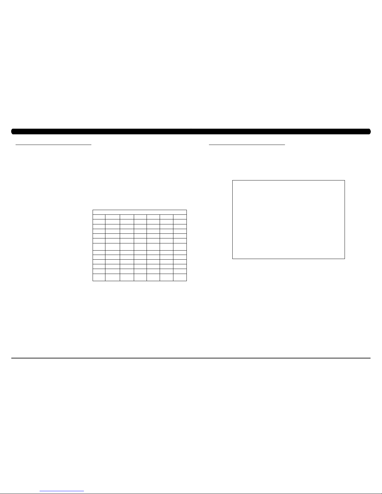
FITNESSTEST(SUBMAXIMAL)- The Submaximal test
measures cardiovascular fitness and provides an estimated Sub-maximal
VO2 max result. This assessment is a 4 stage test lasting 3-5 minutes
where the speed is increased until your Heart Rate is between 115 - 150
bpm for 2 of the stages. When the test is complete, a Fitness Rating is
displayed as High, Good, Average, Fair, or Low along with your age and
VO2 max. The test requires constant monitoring of the user's heart rate,
so the use of a telemetric heart rate strap is highly recommended.
FITNESS RATING NORMS (V02 MAX)
AGE 20-29 30-39 40-49 50-59 60+
MEN
HIGH 51.4+ 50.4+ 48.2+ 45.3 42.5+
GOOD 51.3-46.8 50.3-44.6 48.1-41.8 45.2-38.5 42.4-35.3
AVERAGE 46.7-42.5 44.5-41.0 41.7-38.1 38.4-35.2 35.2-31.8
FAIR 42.4-39.5 40.9-37.4 38.0-35.1 35.1-32.3 31.7-28.7
LOW 39.4 OR
LESS
37.3 OR
LESS
35.0 OR
LESS
32.2 OR
LESS
28.6 OR
LESS
WOMEN
HIGH 44.2+ 41.0+ 39.5+ 35.2+ 35.2
GOOD 44.1-38.1 40.9-36.7 39.4-33.8 35.1-30.9 35.1-29.4
AVERAGE 38.0-35.2 36.6-33.8 33.7-30.9 30.8-28.2 29.3-25.8
FAIR 35.1-32.3 33.7-30.5 30.8-28.3 28.1-25.5 25.7-23.8
LOW 32.2 OR
LESS
30.4 OR
LESS
28.2 OR
LESS
25.4 OR
LESS
23.7 OR
LESS
4.2 WORKOUT SETUP STEPS
CHAPTER 4: CONSOLE OVERLAY AND WORKOUT DESCRIPTION
The Manager's Custom Mode allows the club owner to customize the Climb Mill for the club.
1) To enter Manager Mode, press ENTER, 1, 0, 0, 1, ENTER on the lower keypad. Manager Mode will appear on the display (Figure A).
2) Follow the prompts to change the desired setting.
3) Press the ENTER key once the desired setting is correct to save.
4) Press HOME to return to normal operation. note: If a setting has been changed, the unit and console power should be reset. Cycle the
power switch, and press and hold the CHANNEL UP and CHANNEL DOWN keys for 3-5 seconds to reset the console power.
5.1 MANAGER MODE OVERVIEW
FIGURE A
CHAPTER 5: MANAGER MODE
Page 9
13
12
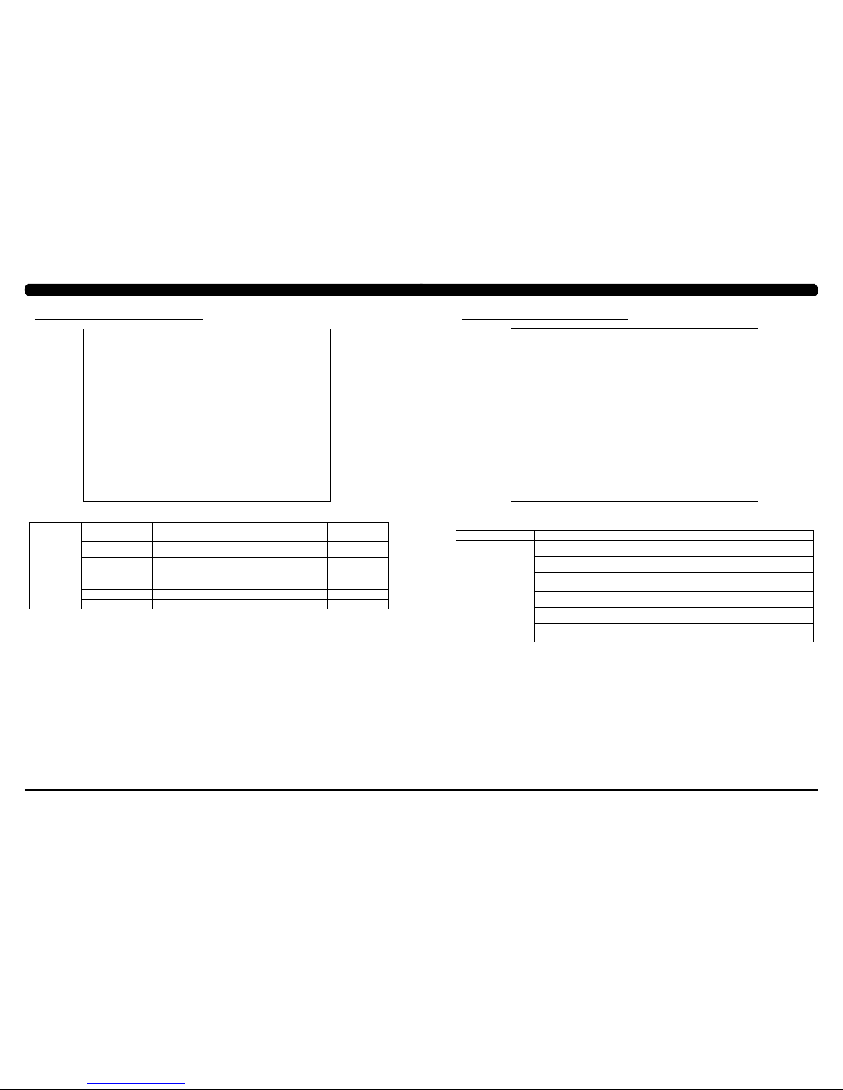
5.2 MANAGER MODE - ABOUT TAB
FUNCTION & DEFAULTS DESCRIPTIONS MODIFIED
Serial Number This option displays the serial number of the
platform and console. See Service Mode to
edit the serial numbers.
Cannot be modified.
Accumulated Distance Total distance on the unit since production. Cannot be modified.
Accumulated Time Total time on the unit since production. Cannot be modified.
Software Versions Software version. Cannot be modified.
Out of Order
Default: Off
This option allows the club to show the unit
"out of order" if an error is present.
On / Off
CSafe Model This option controls whether the console is
Fitlinxx compatible.
LMM / MMM / LAM
MANAGER MODE
About
CHAPTER 5: MANAGER MODE
5.3 MANAGER MODE - TIME TAB
FUNCTION & DEFAULTS DESCRIPTIONS MODIFIED
Maximum Time
Default: 60 Minutes
This option allows the club to set the maximum
workout duration limits during peak and non peak
hours.
Maximum: 99 Minutes
Minimum: 5 Minutes
Default Time Default: 30 Minutes This option controls the default program time. Maxi: Max Time Min: 5 Minutes
Pause Time Default: 5 Minutes This option controls the default pause time. Max: 10 Min Min: 1 Minute
MANAGER MODE
Time
CHAPTER 5: MANAGER MODE
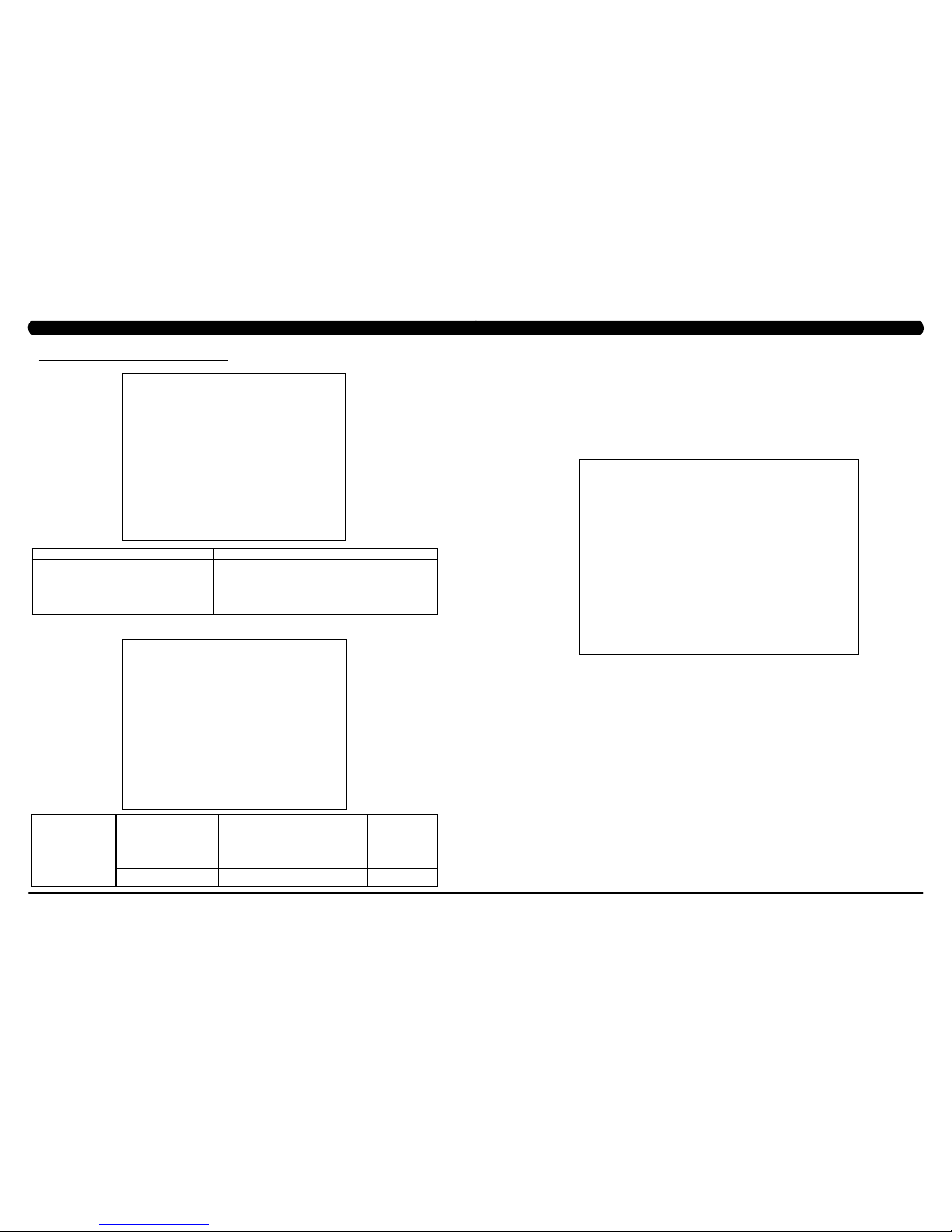
5.4 MANAGER MODE - CLIMB MILL TAB
FUNCTION & DEFAULTS DESCRIPTIONS MODIFIED
Adjust Resistance Offset
Default: 0
This option allows the engineer to set the
resistance offset of SPM adjustment.
Maximum: -10 Min: 10
Default Demand Floor Default: 20 This option controls the default floor. Maximum: 200 Min: 15
Default Target Calories Default: 100 This option controls the default calories. Maximum: 5000 Min: 150
MANAGER MODE
Climb Mill
C7xe-03-C - If the unit has the LMM board, the CSafe
Model should be set for LMM.
C7xe-04-C - If the unit has the LA console (the
console cover back will have holes for ventilation), the
CSafe Model should be set for LAM.
C7xe-01-C or C7xe-02-C - If the unit has the old MMM
board, the CSafe Model should be set for MMM (even
if the MMM console is replaced).
Page 10
15
14
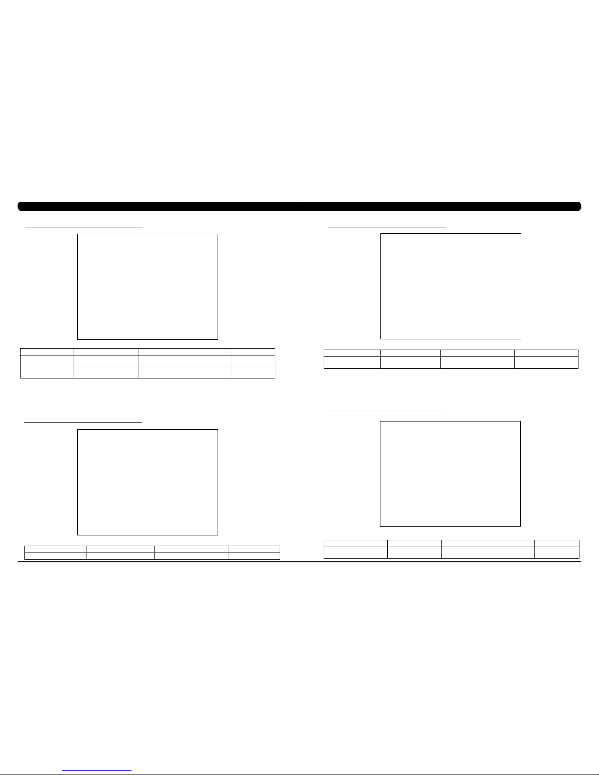
5.5 MANAGER MODE - DEFAULTS TAB
FUNCTION & DEFAULTS DESCRIPTION MODIFIED
Default Level Default: 1 This option controls the default program level. Max: 1 Min: 20
Default Age Default: 30 This option controls the default user's age used in the target HR
calculations.
Max: 100 Min: 10
Default Weight
Default: 150 lbs / 68 kg
This option controls the default weight used in the calorie
calculations. Displayed in pounds or kilograms.
Max: 400 lbs / 182 kg
Min: 50 lbs / 22 kg
Default Height
Default: 68" / 173cm
This option controls the default height. Max: 49" / 101cm
Min: 90" / 228cm
Gender Default: Male Setting the user as Male or Female. Male or Female
Key Sound Default: Yes This option allows different sounds to be chosen for the keypad. Yes or No
MANAGER MODE
Defaults
CHAPTER 5: MANAGER MODE
5.6 MANAGER MODE - TV TAB
CHAPTER 5: MANAGER MODE
FUNCTION & DEFAULTS DESCRIPTIONS MODIFIED
Default Channel
Default: 3
This option controls the default TV channel
on start up.
Channels 1-999
Default Volume
Default: 5
This option controls the default TV volume
on start up.
Maximum: 17
Minimum: 1
Tuner Available Default: Yes This option controls the default TV function. Yes or No
Setup This option sets the TV tuner function. On / Off
Remote TV
Default: No
This option controls the remote TV function. ON or YES
Remote TV channel
Default: 1
This option controls the default remote TV
channel on start up.
Maximum: 37
Minimum: 1
Remote TV volume
Default: 15
This option controls the default remote TV
volume on start up.
Maximum: 15
Minimum: 1
MANAGER MODE
TV
Page 11
17
16
5.7 MANAGER MODE - LANGUAGE TAB
MANAGER MODE FUNCTION & DEFAULTS DESCRIPTIONS MODIFIED
Language Select default language. This option allows the user to select a flag for a
specific language.
Sets the language for the
console. Select between
English, Spanish, German,
French, Italian, Portuguese,
Finnish, Japanese, Swedish,
Dutch, Welsh, Turkish or
Polish.
CHAPTER 5: MANAGER MODE
FUNCTION & DEFAULTS DESCRIPTIONS MODIFIED
Asset Management
Default: Off
This option allows fitness clubs to collect workout
data to a PC.
On or Off
Virtual Active
Default: Off
This option controls the Virtual Active function.
note: Virtual Active only works in AC Plug In
Mode.
On or Off
E-Stop Default: On This option controls the E-Stop function. On or Off.
ENGINEERING MODE
Other
5.8 MANAGER MODE - OTHER TAB
6.1 ENGINEERING MODE OVERVIEW
The Engineering Mode allows the club owner to keep track of the technical settings and error history for the Climb Mill.
1) To enter Engineering Mode, press ENTER, 2, 0, 0, 1, ENTER on the lower keypad. Engineering Mode will appear on the display (Figure A).
2) Follow the prompts to change the desired setting.
3) Press the ENTER key once the desired setting is correct to save.
4) Press HOME to return to normal operation. note: If a setting has been changed, the unit and console power should be reset. Cycle the
power switch, and press and hold the CHANNEL UP and CHANNEL DOWN keys for 3-5 seconds to reset the console power.
FIGURE A
CHAPTER 6: ENGINEERING MODE
Page 12
19
18
FUNCTION & DEFAULTS DESCRIPTIONS MODIFIED
RPM Low Limit Charge:
Default: 10
This option controls the RPM low limit to iPod
charge.
Range: 0 - 255
RPM Low Limit Resistance
Default: 10
This option control the RPM low limit to show
resistance.
Range: 0 - 255
ENGINEERING MODE
Calibration
6.2 ENGINEERING MODE - CALIBRATION TAB
ENGINEERING MODE FUNCTION & DEFAULTS DESCRIPTIONS MODIFIED
Statistics This option displays the workout history. N/A
6.3 ENGINEERING MODE - STATISTICS TAB
CHAPTER 6: ENGINEERING MODE
ENGINEERING MODE FUNCTION & DEFAULTS DESCRIPTIONS MODIFIED
Errors This option displays the error code
history.
N/A
6.4 ENGINEERING MODE - ERRORS TAB
6.5 ENGINEERING MODE - CLUBS TAB
ENGINEERING MODE FUNCTION & DEFAULTS DESCRIPTIONS MODIFIED
Clubs
Default: MATRIX
This option allows the club to select a screen
header from a list.
N/A
CHAPTER 6: ENGINEERING MODE
Page 13

21
20
6.6 ENGINEERING MODE - CLUB ID TAB
ENGINEERING MODE FUNCTION & DEFAULTS DESCRIPTIONS MODIFIED
Club ID This option records the Club ID of
the fitness facility.
N/A
6.7 ENGINEERING MODE - CLIMB MILL TAB
FUNCTION & DEFAULTS DESCRIPTIONS MODIFIED
Safety Threshold Default: 100 This option controls the safety threshold for the
E-Stop function.
Maximum: 500
Minimum: 4
Footplant test This option shows the footplate reaction value for
troubleshooting.
N/A
ENGINEERING MODE
Climb Mill
CHAPTER 6: ENGINEERING MODE
ENGINEERING MODE FUNCTION & DEFAULTS DESCRIPTIONS MODIFIED
Other Erp Time
Default: 0 minutes
If there is no use of the machine over a
period of time, the console LEDs will turn
off (go into ErP mode).
Maximum: 30 minutes
Minimum: 0
6.8 ENGINEERING MODE - OTHER TAB
CHAPTER 6: ENGINEERING MODE
Page 14
23
22
The Service Mode allows an authorized service provider to test and store information on the Climb Mill.
1) To enter Service Mode, press ENTER, 3, 0, 0, 1, ENTER on the lower keypad. Service Mode will appear on the display (Figure A).
2) Follow the prompts to change the desired setting.
3) Press the ENTER key once the desired setting is correct to save.
4) Press HOME to return to normal operation. note: If a setting has been changed, the unit and console power should be reset. Cycle the
power switch, and press and hold the CHANNEL UP and CHANNEL DOWN keys for 3-5 seconds to reset the console power.
FIGURE A
7.1 SERVICE MODE OVERVIEW
CHAPTER 7: SERVICE MODE
FUNCTION & DEFAULTS DESCRIPTIONS
Machine Type: Climb Mill This option selects the current model.
Serial Number This option displays the serial number of the console and frame.
Accumulated Floors This option displays the accumulated workout floors since production.
Accumulated Time This option displays the accumulated workout time since production.
Show Service on Boot Factory Setting Only.
SERVICE MODE
Setup
7.2 SERVICE MODE - SETUP TAB
CHAPTER 7: SERVICE MODE
Page 15
25
24
CHAPTER 7: SERVICE MODE
7.3 SERVICE MODE - TEST TAB
FUNCTION & DEFAULTS DESCRIPTIONS MODIFIED
Keypad This option is for a keypad test. N/A
Touch Calibration This option allows for a touch calibration of the
console. Follow the cross mark and touch the
screen to catch. After 5 positions are tested, touch
the center of the screen to exit this test.
N/A
Keypad Type This option sets the keypad type for the console. Quick Start or No Quick Start or
LAM
Radio Test This option will test the radio signal for function. N/A
SERVICE MODE
Test
C7xe-04-C Keypad - New keypad -
C7xe-01--C or C7xe-02-C Keypad - Old
keypad - Includes Quick Start Key
C7xe-03--C Keypad - Old keypad - Does
NOT Includes Quick Start Key
SERVICE MODE FUNCTION & DEFAULTS DESCRIPTIONS
Log This option allows the club to record key
components replacement history.
7.4 SERVICE MODE - LOG TAB
7.5 SERVICE MODE - DATE & TIME TAB
FUNCTION & DEFAULTS DESCRIPTIONS
Date & Time This option sets the current date and time of the
machine.
SERVICE MODE
CHAPTER 7: SERVICE MODE
Page 16
27
26
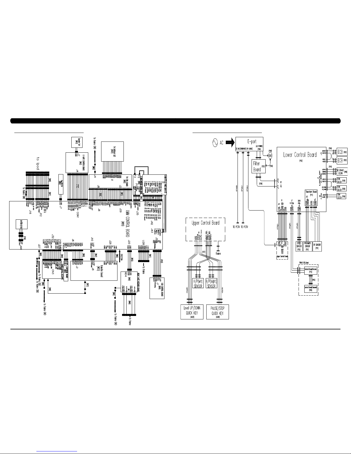
8.1 ELECTRICAL DIAGRAMS
CHAPTER 8: TROUBLESHOOTING
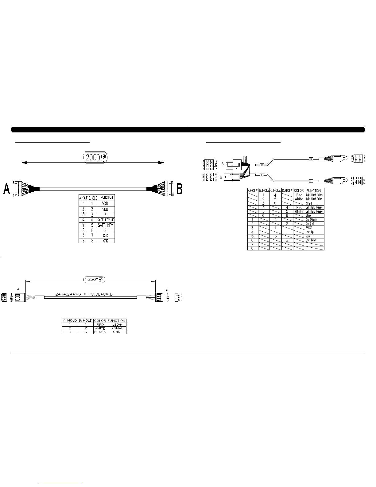
8.1 ELECTRICAL DIAGRAMS - CONTINUED
CHAPTER 8: TROUBLESHOOTING
Page 17
29
28
P01 - DIGITAL COMMUNICATION WIRE
P13- SPEED SENSOR EXTENSION WIRE
8.1 ELECTRICAL DIAGRAMS - CONTINUED
CHAPTER 8: TROUBLESHOOTING
8.1 ELECTRICAL DIAGRAMS - CONTINUED
CHAPTER 8: TROUBLESHOOTING
P27 - HAND PULSE WIRES
Page 18

31
30
P31 - PROXIMITY SENSOR WIRE
8.1 ELECTRICAL DIAGRAMS - CONTINUED
CHAPTER 8: TROUBLESHOOTING
P04 - ECB LOAD WIRE
8.1 ELECTRICAL DIAGRAMS - CONTINUED
CHAPTER 8: TROUBLESHOOTING
P19 - POWER SENSOR WIRE
P18 - CONTROL ZONE SENSOR WIRE
Page 19

33
32
8.1 ELECTRICAL DIAGRAMS - CONTINUED
CHAPTER 8: TROUBLESHOOTING
G18 - H/P CONNECT WIRE
P51 - IR SENSOR WIRE
8.2 LCB ERROR INDICATORS
CHAPTER 8: TROUBLESHOOTING
Page 20

35
34
8.2 LCB ERROR INDICATORS - CONTINUED
CHAPTER 8: TROUBLESHOOTING
LED STATUS DESCRIPTION
LED1 LCB status (blinking: OK).
LED2 Start or Stop( bright: start )
LED3 Safety stop ( bright: action )
LED4 Safety Key action status ( bright: trigger )
LED5 LCB Error status
LED6 UCB and LCB connection status (blinking: OK)
Status LED
---------------------------------------------------------------------------------Firmware definition-----------------------------------------------------------------------------------
--------------------------------------------------------------------------------
Hardware definition-----------------------------------------------------------------------------------
LED STATUS DESCRIPTION
LED7 MCU power lamp
LED8 Electro-magnet device 2 PWM lamp
LED9 Electro-magnet device 2 fan lamp
LED10 Electro-magnet device 1 PWM lamp
LED11 Electro-magnet device 1 fan lamp
LED12 DC brake release lamp
LED13 DC 26V lamp
D12 Safety switch power lamp
D35 RPM lamp
D8 Positioning sensor lamp
D15 DC 12V lamp
8.3 ERROR CODE TROUBLESHOOTING - 01AC
CHAPTER 8: TROUBLESHOOTING
ERROR CODE 01AC
1) SYMPTOM:
a. 01AC - Electro magnet (ECB) over current.
2) SOLUTION:
a. On standby mode, measure the resistance on ECB1 and ECB2. Please check the ECB extension cable connection at the LCB (pins 1 &
3 for ECB1, pins 2 & 4 for ECB2), there should be between 12.8 ~ 14.2 ohms. (Figure A)
- If the ECB resistance is out of the range, replace the ECB.
- If the ECB resistance is within the range, replace the LCB.
b. Check the gap of ECB1 and ECB2. There should be a gap of .5mm between the ECB and the flywheel.
- Adjust the gap as shown in Section 9.16.
FIGURE A
Page 21

37
36
8.4 ERROR CODE TROUBLESHOOTING - 01AF
CHAPTER 8: TROUBLESHOOTING
FIGURE A
ERROR CODE 01AF
1) SYMPTOM:
a. 01AF - Electro magnet (ECB) disconnected.
2) SOLUTION:
a. Check the connection of the ECB extension cable from the LCB to the ECB (Figure A).
b. Check to see if LED8 and LED10 on the LCB have a brief light for 3 second when you power on machine.
- If LED8 and LED10 do not have a brief light, replace the LCB.
- If LED8 and LED10 do have a brief light, check the ECB extension cable connection at the LCB (pins 1 & 3 for ECB1, pins 2 & 4 for
ECB2), there should be between 12.8 ~ 14.2 ohms. (Figure B)
- If the ECB resistance is out of the range, replace the ECB.
- If the ECB resistance is within the range, replace the LCB.
b. Check the gap of ECB1 and ECB2 (Figure B). There should be a gap of .5mm between the ECB and the flywheel.
- Adjust the gap as shown in Section 9.16.
FIGURE B
CHAPTER 8: TROUBLESHOOTING
8.5 ERROR CODE TROUBLESHOOTING - 02A0
ERROR CODE 02A0
1) SYMPTOM:
a. 02A0 - Encoder error.
b. The unit is in PAUSE Mode at all times.
2) SOLUTION:
a. Check the connection of the speed sensor cable from the LCB to the speed sensor.
b. Check to see if LED D35 on the LCB is on when the brake is turned to the left release position (Figure A).
If LED D35 is off, move the stairs about 3 stairs and check to see if LED D35 is flashing.
- If not, replace the speed sensor.
- If yes, adjust the speed sensor position and clean the speed sensor of any debris (Figures B), then re-test.
FIGURE BFIGURE A
Page 22

39
38
8.6 ERROR CODE TROUBLESHOOTING - 02BE / 02BF
ERROR CODE 02BE / 02BF
1) SYMPTOM:
a. 02BE - DC brake error (If movement is detected when the brake is in stop mode).
b. 02BF - DC brake error (The brakes current is over 1A for a continuous 3 sec.).
2) SOLUTION:
a. Check the power extend wire connection between the brake and LCB for any damage (Figures A & B).
b. Check to see if the stairs will move when you are in the stop position. If yes, replace the brake.
CHAPTER 8: TROUBLESHOOTING
FIGURE BFIGURE A
8.7 ERROR CODE TROUBLESHOOTING - 02CO
CHAPTER 8: TROUBLESHOOTING
ERROR CODE 02C0
1) SYMPTOM:
a. 02C0 - DC brake in manual mode.
2) SOLUTION:
a. Check if the DC brake is in the “ Right “ lock position (Figure A). Release the brake (move to the left) if in lock position.
b. Replace the brake.
FIGURE A
Page 23

41
40
8.8 ERROR CODE TROUBLESHOOTING - 02C1
CHAPTER 8: TROUBLESHOOTING
ERROR CODE 02C1
1) SYMPTOM:
a. 02C1 -Speed tracking error (the speed tracking is off by at least 10 rpms for a continuous 20 sec).
2) SOLUTION:
a. Adjust the speed sensor position and clean the speed sensor of any debris (Figure A).
b. Check the ECB extension cable connection at the LCB (pins 1 & 3 for ECB1, pins 2 & 4 for ECB2), there should be between 12.8 ~ 14.2
ohms, check which ECB is outside the range and replace it (Figure B).
FIGURE A FIGURE B
8.9 ERROR CODE TROUBLESHOOTING - 02C2
CHAPTER 8: TROUBLESHOOTING
ERROR CODE 02C2 (Control Zone 3 IR sensors error)
1) SYMPTOM:
a. The control zone 3 IR sensors are no communication or disconnected over 3 seconds.
b. Once power on, the control zone 3 IR sensors are no power or hidden over 3 seconds.
c. After power on, the control zone 3 IR sensors are no power or hidden over 4 hours.
2) SOLUTION:
a. Check if there's something in the control zone 3 IR sensors.
b. Check the connection of the control zone extension cable from the LCB to the control zone 3 IR sensors (Figure A & B).
c. Check if LED1 on the receiver board is flashing (Figure C).
- If yes, measure if the control zone extension cable (white wire- pin2) from the LCB to receiver board of control zone is good (Figure A
& B). Replace it if the cable is defective.
- If not, go to next step to verify.
d. Check if D12 on the LCB is light (Figure D).
- If not, replace the LCB.
- If yes, go to next step to verify.
e. Check LED1 status on the receiver board (control zone).
- If LED1 is light, replace the transmission board.
- If LED1 is off, replace the receiver board.
FIGURE A FIGURE B
FIGURE C FIGURE D
Page 24

43
42
CHAPTER 8: TROUBLESHOOTING
8.11 TROUBLESHOOTING - ERROR 03A5 / 03A6
ERROR CODE 03A5 / 03A6
1) SYMPTOM:
03A5 - After program start, GUI can't load program.
03A6 - After GUI load program, the program can't be started.
2) SOLUTION:
1) Using USB disk to update the latest GUI.
2) If the error still happened after update, replacement LMM board.
8.10 ERROR CODE TROUBLESHOOTING - 02C3
CHAPTER 8: TROUBLESHOOTING
ERROR CODE 02C3 (Frame IR sensors error)
1) SYMPTOM:
a. The frame IR sensors are no communication or disconnected over 3 seconds.
b. Once power on, the frame IR sensors are no power or hidden over 3 seconds.
c. After power on, the frame IR sensors are no power or hidden over 4 hours.
2) SOLUTION:
a. Check if there's something in the control zone 3 IR sensors. (Figure A).
b. Check the connection of the frame IR cable from the LCB to the frame IR sensors (Figure B).
c. Check if LED1 on the small transfer board is flashing (Figure C).
- If not, replace the small transfer board.
- If yes, replace the frame IR cables (transmission & receiver).
FIGURE A FIGURE B
FIGURE C
Page 25

45
44
CHAPTER 8: TROUBLESHOOTING
8.12 TROUBLESHOOTING - ERROR 03A7
ERROR CODE 03A7
1) SYMPTOM:
03A7 – Can not load video in Virtual Active program.
2) SOLUTION:
1) Please remove the SD card from VA board and plug in again.
2) If the error still happened, check the SD card inside have data.
--If yes, replace the VA board.
--If no, replace the SD card.
FIGURE A
CHAPTER 8: TROUBLESHOOTING
8.13 TROUBLESHOOTING - ERROR 03A8
ERROR CODE 03A8
1) SYMPTOM:
03A8 - Machine type setting is not matched to LCB or MCB.
2) SOLUTION:
1) Check if the console machine type is matched with the correct frame.
Page 26
47
46
8.14 ERROR CODE TROUBLESHOOTING - 04A0
CHAPTER 8: TROUBLESHOOTING
ERROR CODE 04A0
1) SYMPTOM:
a. 04A0 - UCB has no communication or is disconnected.
2) SOLUTION:
a. Check the console cable connections at the LCB and UCB (Figure A & B).
b. Replace the console cable.
c. Replace the UCB.
FIGURE BFIGURE A
8.15 ERROR CODE TROUBLESHOOTING - 04B0
CHAPTER 8: TROUBLESHOOTING
ERROR CODES 04B0
1) SYMPTOM:
a. 04B0 - LCB no communication response for over 3 seconds. .
2) SOLUTION:
a. Check the console cable connections at the LCB and UCB (Figure A & B).
b. Replace the console cable.
c. Replace the LCB.
FIGURE A FIGURE B
Page 27

49
48
8.16 TROUBLESHOOTING - NO POWER TO THE CONSOLE
CHAPTER 8: TROUBLESHOOTING
NO POWER TO THE CONSOLE
1) SYMPTOM:
a. The incoming power is not correct.
b. UCB damage.
c. Console cable damage.
d. LCB damage.
2) SOLUTION:
a. Verify that the outlet is outputting the correct voltage based on local standards (110V - 220V). Try a known good outlet if any problems
are present.
b. Remove the console and use a multi-meter to check DC voltage across pins 1 and 8 of the console cable. There should be 12V present.
- If there is 12V present, check the switch on the UCB. It should be pointed towards the right and LED 1 should be lit (Figure A).
- If LED D18 is not lit, replace the console.
c & d. Check if LED D15 on the LCB is lit (Figure B).
- If LED D15 is lit, replace the console cable.
- If LED D15 is not lit, or does not light after replacing the console cable, replace the LCB.
FIGURE BFIGURE A
8.17 TROUBLESHOOTING - HEART RATE ISSUES
HEART RATE ISSUES
1) SYMPTOM:
a. No heart rate.
b. Erratic or consistently high heart rate.
2) SOLUTION:
a. With a multi-meter set for DC Voltage, place one prong of the multi-meter on each of the heart rate plates on the handlebar (Figure A).
A correctly connected HR grip will have a DC Voltage reading of between .5 and 2.0VAC. Repeat this step on both HR grips. If this reading is
correct, skip to Step b. If not continue with Step a.
- Remove the screws holding the 2 halves of the HR grip together (Figure B).
- Check the connection of the heart rate grip wiring to the grips (Figure C). Replace the HR grips if any damage is seen to the plates.
- Loosen the 6 handlebar screws on each side of the unit (Figure D).
CHAPTER 8: TROUBLESHOOTING
FIGURE A
FIGURE DFIGURE C
FIGURE B
Page 28

51
50
CHAPTER 8: TROUBLESHOOTING
8.17 TROUBLESHOOTING - HEART RATE ISSUES - CONTINUED
- Remove the 2 screws going into the handlebar connection frame from the bottom (Figure E).
- Remove the 3 screws going into the handlebar connection frame from the top (Figure F).
- Pull the handlebars out of the handlebar connection frame, and disconnect the HR wiring on each side (Figure G).
- Remove the handlebar connection frame from the unit (Figure H).
- Perform a continuity test on the wiring going from the HR grip to the handlebar connection frame. With a multi-meter set for ohms,
place one prong on the HR grip wiring coming out of the handlebar (Figure I) and one prong on the HR plate. The HR wiring is red, black, and
white (match red with red and white with white). For example, the red wire on the left HR grip wiring should correspond with the left top plate.
An ohm reading of less than 1 should be expected. If this reading is higher than 1, or if there is not a reading, replace this section of the HR
grip wiring.
- Repeat the previous step with the opposite side HR grip wiring (Figure J).
FIGURE FFIGURE E
FIGURE JFIGURE I
FIGURE HFIGURE G
8.17 TROUBLESHOOTING - HEART RATE ISSUES - CONTINUED
CHAPTER 8: TROUBLESHOOTING
- Remove the console and perform a continuity test on the wiring going from the handlebar connection frame to the console. With a
multi-meter set for ohms, place one prong on the HR grip wiring coming out of the console mast (Figure K) and one prong on the wiring that
connects to the handlebar wiring (Figure L - match red with red and white with white). An ohm reading of less than 1 should be expected. If this
reading is higher than 1 or if there is not a reading, replace this section of HR grip wiring.
b. If your problem is not with the HR grips, a continuity check should be performed on the unit to verify that the console is properly grounded
(see Service Bulletin – Continuity Test on Matrix Climb Mills).
- Once the console grounding has been verified, the heart rate board ground wire should be verified.
- Remove the 6 screws holding the console back to the front (Figure M).
- Check to make sure that the HR board ground wire is plugged into the console ground wire that plugs into the ground wire run down the
console mast. Retest for HR if not properly connected.
- Remove the 2 screws holding the HR board to the console frame.
- With your multi-meter set for ohms, place one prong of your multi meter on the ground wire coming from the HR board (Figure N) and
the other on the console ground wire that comes out of the console and plugs into the ground wire going down the console mast. An ohm
reading of less than 1 should be expected. If this is higher than 1 or if there is not a reading, replace the HR board ground wire.
- If no problems were found using the troubleshooting above, replace the HR board.
- If the HR board does not solve the issue, replace the console.
FIGURE LFIGURE K
FIGURE NFIGURE M
Page 29
53
52
CHAPTER 8: TROUBLESHOOTING
8.18 TROUBLESHOOTING - TOGGLE ISSUES
TOGGLE ISSUES
1) SYMPTOM:
a. No response on the grip toggles
b. The console beeps when the toggles are pressed, but no change on console.
2) SOLUTION:
a. Remove the screws holding the 2 halves of the HR grip together (Figure A).
- Check the connection of the toggle wiring to the toggle keypad (Figure B). note: There should be a red dot on both the toggle
harness and the grip wiring indicating the correct way to plug in the toggles (the red dots should be on the same side of the connector).
- Place a screwdriver or other metal object between pins 1 & 2 and 2 & 3 on the grip wiring (Figure C). The console should beep when
these wires are bridged. If the console beeps, replace the toggles. If the console does not beep, continue with the steps below.
- Loosen the 6 handlebar screws on each side of the unit (Figure D).
FIGURE A FIGURE B
FIGURE DFIGURE C
- Remove the 2 screws going into the handlebar connection frame from the bottom (Figure E).
- Remove the 3 screws going into the handlebar connection frame from the top (Figure F).
- Pull the handlebars out of the handlebar connection frame, and disconnect the grip wiring on each side (Figure G).
- Remove the handlebar connection frame from the unit (Figure H).
- Perform a continuity test on the wiring going from the toggle to the handlebar connection frame. With a multi-meter set for ohms, place
one prong on the toggle wiring coming out of the handlebar (Figure I) and one prong on the wire on the toggle connector (the toggle wires are
yellow, blue, and green - match similar colors). An ohm reading of less than 1 should be expected. If this reading is higher than 1, or if there is
not a reading, replace this section of the grip wiring.
- Repeat the previous step with the opposite side grip wiring (Figure J).
FIGURE FFIGURE E
FIGURE JFIGURE I
FIGURE HFIGURE G
8.18 TROUBLESHOOTING - TOGGLE ISSUES - CONTINUED
CHAPTER 8: TROUBLESHOOTING
Page 30
55
54
CHAPTER 8: TROUBLESHOOTING
8.18 TROUBLESHOOTING - TOGGLE ISSUES - CONTINUED
- Remove the console and perform a continuity test on the wiring going from the handlebar connection frame to the console. With
a multi-meter set for ohms, place one prong on the grip wiring coming out of the console mast (Figure K) and one prong on the wiring that
connects to the handlebar wiring (Figure L - match blue with blue, green with green, and yellow with yellow). An ohm reading of less than 1
should be expected. If this reading is higher than 1 or if there is not a reading, replace this section of grip wiring.
b. If your problem is not with the toggles or toggle wiring, the issue is likely with the console.
FIGURE LFIGURE K
8.19 TV TROUBLESHOOTING - OVERVIEW
CHAPTER 8: TROUBLESHOOTING
Sections8.19-8.22will assistwithdiagnosingproblemswith TVandentertainmentrelatedequipmentsold
byMatrixFItnessEquipment.
The Matrix 7xe console includes an integrated TV that shows in the large display window. The TV is capable of being shown as a 7" or 15"
screen (Figures A & B). The console should be equipped with an entertainment keypad similar to Figure C.
FIGURE A
FIGURE B
FIGURE C
Page 31
57
56
8.20 TV TROUBLESHOOTING - PICTURE FUZZY OR UNCLEAR
1) For a fuzzy or unclear picture, see the TV programming instructions in Section 10. If the TV is still fuzzy or unclear after programming:
a) Check the coax connection at the entertainment port (Figure A).
b) Remove the 5 screws holding the console to the console mast and check the coax connection at the console (Figure B).
c) Use a verified good piece of coax cable (a good coax cable will have a signal strength of 10hz or greater) to plug directly into the back
of the console bypassing the entertainment port. If this resolves the issue, replace the internal coax cable.
d) If plugging the coax cable into the back of the console does not resolve the issue, remove the console back and check the console
cable connection at the tuner (Figure C).
e) Check the internal cables and fitting inside your machine at the console and below the front shroud (Figure D). Make sure you have
no kinks, cuts, or poor connectors at the end of the cable. Fittings should have a clean flush connector with no stray aluminum strands touching
the center conductor. Replace any suspect cables.
f) If no damage can be found on the cables, fittings, or connectors, and hooking the coax directly to the back of the console does not
resolve the issue, replace the TV tuner.
FIGURE A
FIGURE B
FIGURE C FIGURE D
CHAPTER 8: TROUBLESHOOTING
1) Remove the console back and check the electrical connections for the TV (Figures A & B).
2) After you have verified that all connects are secure, and the problem still persists, verify power at the outlet (Figure C). If the outlet is not
outputting 120V, check the fitness room power.
3) If internal electrical connections are good, and the outlet is outputting 120V, the issue is likely with the TV. Replace the console.
8.21 TV TROUBLESHOOTING - TV WILL NOT TURN ON
CHAPTER 8: TROUBLESHOOTING
FIGURE C
FIGURE BFIGURE A
Page 32

59
58
8.22 TV TROUBLESHOOTING - ENTERTAINMENT KEYPAD ISSUES
ENTERTAINMENT KEYPAD IS NOT WORKING
1) SYMPTOM:
a. The entertainment keypad (Figure A) is not responding.
2) SOLUTION:
a. Remove the console and check the connection of the entertainment keypad (Figure B).
b. If the entertainment keypad cable is pinched, kinked, or cut replace the keypad.
c. If replacing the keypad does not resolve the issue, replace the console.
FIGURE A
FIGURE B
CHAPTER 8: TROUBLESHOOTING CHAPTER 9: PART REPLACEMENT GUIDE
9.1 SIDE COVER REPLACEMENT
1) Turn off power and disconnect the cord from the machine.
2) Pull up on the Control Zone carefully (Figure A).
3) Unplug the wire connector from the Control Zone and remove the Control Zone from the unit (Figure B).
4) Remove the 3 screws and remove the small Matrix logo cover at the top of the stairs (Figures C & D).
FIGURE A FIGURE B
FIGURE C
FIGURE D
Page 33

61
60
CHAPTER 9: PART REPLACEMENT GUIDE
9.1 SIDE COVER REPLACEMENT - CONTINUED
5) Rotate the 2 plastic clips counter-clockwise to remove the Matrix logo cover (Figures E & F).
6) Remove the 4 screws holding the side cover to the frame and pull up on the side cover to remove it (Figures G & H).
7) Reverse Steps 1-6 to install a new side cover.
FIGURE E FIGURE F
9.2 CONSOLE REPLACEMENT
1) Turn off power and disconnect the cord from the machine.
2) Remove the 5 screws that hold the console to the console mast (Figure A).
3) Disconnect the console cable and other wiring from the console, then remove the console (Figure B).
4) Connect the wiring to the new console.
5) Carefully push the wires into the console and console mast until they are clear of the console / mast connection.
6) Attach the console to the console mast using the screws removed in Step 2.
7) Test the Climb Mill for function as outlined in Section 9.21.
FIGURE BFIGURE A
CHAPTER 9: PART REPLACEMENT GUIDE
Page 34

63
62
CHAPTER 9: PART REPLACEMENT GUIDE
9.3 CONSOLE KEYPAD / OVERLAY REPLACEMENT
note: The instructions below are for console overlays / keypads replacement, but the procedure is the same regardless of where the overlay /
keypad is.
1) Remove the console as outlined in Section 9.2.
2) Remove the back cover of the console (Figure A).
3) Unplug and remove the faulty overlay (Figure B).
4) Clean the console area with alcohol to remove any left over adhesive (Figure C).
5) Peel part of the protective film from the back of the overlay / keypad (Figure D).
FIGURE A
FIGURE B
FIGURE C FIGURE D
CHAPTER 9: PART REPLACEMENT GUIDE
FIGURE E FIGURE F
FIGURE G FIGURE H
8) Press down on the corners of the overlay / keypad to keep it in place. Then remove the protective film (Figure G).
9) Once the overlay / keypad is in the correct position, press down on it to adhere it in positions (Figure H).
10) Use the same procedure to replace any additional faulty overlays / keypads. note: Overlays / keypads cannot be re-used.
11) Test the Climb Mill for function as outlined in Section 9.21.
6) Push the overlay / keypad ribbon cable through the hole in the console and plug it in (Figure E).
7) Match the overlay / keypad to the cutout in the console (Figure F).
9.3 CONSOLE KEYPAD / OVERLAY REPLACEMENT - CONTINUED
Page 35

65
64
9.4 FRONT SHROUD REPLACEMENT
1) Turn off power and disconnect the cord from the machine.
2) Remove all of the cables from the front cover (Figure A).
3) Remove the 2 screws from the front cover and remove it (Figure B).
4) Remove both side covers as outlined in Section 9.1.
5) Remove the console as outlined in Section 9.2.
6) Remove the 3 screws on each side that connect the front shroud to the frame (Figure C).
7) Remove the 5 screws that hold the upper handlebar set to the console mast (Figure D).
FIGURE D
FIGURE B
FIGURE C
FIGURE A
CHAPTER 9: PART REPLACEMENT GUIDE
9.4 FRONT SHROUD REPLACEMENT - CONTINUED
CHAPTER 9: PART REPLACEMENT GUIDE
8) Disconnect the hand pulse and quick key cables on the inside of the console mast (Figure E).
9) Remove the 8 screws holding the lower handlebar set to the console mast (Figure F).
10) Remove the 4 screws that attach the console mast to the frame (Figure G).
11) Pull the cables out of the console mast and remove it (Figure H).
12) Remove the 4 screws holding the front shroud to the sides (Figure I).
13) Pull up on the front shroud and remove it (Figure J).
14) Reverse Steps 1-13 to install a new front shroud.
15) Test the Climb Mill for function as outlined in Section 9.21.
FIGURE E
FIGURE F
FIGURE H
FIGURE G
FIGURE JFIGURE I
Page 36

67
66
CHAPTER 9: PART REPLACEMENT GUIDE
9.5 LOWER CONTROL BOARD (LCB) REPLACEMENT
1) Turn off power and disconnect the cord from the machine.
2) Remove all wiring from the front cover and remove it from the machine as outlined in Section 9.4.
3) Disconnect all wiring from the LCB (Figure A).
4) Remove the 2 screws holding the LCB to the frame and remove the LCB (Figure B).
5) Remove the 2 screws that hold the fan to the LCB and remove it (Figure C).
6) Reverse Steps 1-5 to install a new LCB.
7) Test the Climb Mill for function as outlined in Section 9.21.
FIGURE A FIGURE B
FIGURE C
CHAPTER 9: PART REPLACEMENT GUIDE
9.6 UPPER HANDLEBAR REPLACEMENT
FIGURE A FIGURE B
1) Turn off power and disconnect the cord from the machine.
2) Remove the 5 screws holding the upper handlebar set to the console mast (Figure A).
3) Pull out the right handlebar and hand grip cable (Figure B).
4) Disconnect the wiring that connects the left hand grip cable to the hand pulse extension wire (Figure C).
5) Pull out the left handlebar and hand grip cable (Figure D).
FIGURE D FIGURE C
Page 37

69
68
CHAPTER 9: PART REPLACEMENT GUIDE
9.6 UPPER HANDLEBAR REPLACEMENT SET - CONTINUED
6) Disconnect the wire that connects the left hand grip cable to the hand pulse extension wire (Figure E).
7) Remove the 2 screws on each side holding the front of the upper handlebar set to the lower handlebar set (Figure F).
8) Remove the 2 screws on each side holding the rear of the upper handlebar set to the lower handlebar set (Figure G).
9) Reverse Steps 1-8 to install a new upper handlebar set.
10) Test the Climb Mill for function as outlined in Section 9.21.
FIGURE E
FIGURE F
FIGURE G
9.7 LOWER HANDLEBAR SET REPLACEMENT
CHAPTER 9: PART REPLACEMENT GUIDE
1) Turn off the power and disconnect the cord from the machine.
2) Remove the upper handlebar set as outlined in Section 9.6.
3) Remove the 8 screws holding the lower handlebar set to the console mast (Figure A).
4) Remove the 2 screws holding the lower handlebar set to the frame handlebar set, then remove the lower handlebar (Figure B).
5) Reverse Steps 1-4 to install a new lower handlebar set.
6) Test the Climb Mill for function as outlined in Section 9.21.
FIGURE A FIGURE B
Page 38

71
70
9.8 HANDLEBAR SERVICE
CHAPTER 9: PART REPLACEMENT GUIDE
1) Turn off the power and disconnect the cord from the machine.
2) All items on the handlebar are removed using a Phillips screwdriver from the underside of the bar.
3) Once the screws are removed, lift the part carefully then disconnect any wire connections to fully remove the part. This includes any
resistance, pause / stop buttons, and the heart rate grip plates (Figures A & B).
4) Test the Climb Mill for function as outlined in Section 9.21.
FIGURE A
FIGURE B
9.9 STAIR REPLACEMENT
CHAPTER 9: PART REPLACEMENT GUIDE
1) Turn off power and disconnect the cord from the machine.
2) Remove the side covers as outlined in Section 9.1.
3) Remove the front shroud as outlined in Section 9.4.
4) Turn the brake bar to the right to lock the stairs in place (Figure A).
5) Remove the X shaped clip from the long axle on the upper side of the stair needing to be replaced (Figure B).
6) Pull out the axle from the opposite side that you removed the X shaped clip from (Figure C). note: 1. Pay attention to the order of the parts
sequence on the axle as you remove it (Figure D). The correct parts sequence is X shaped clip > bearing > washer > chain > spacer > stair. 2.
Do not reuse the X-washer retainers. Order replacements with your stair or bearing order.
FIGURE A FIGURE B
FIGURE C
FIGURE D
Page 39

73
72
9.9 STAIR REPLACEMENT - CONTINUED
CHAPTER 9: PART REPLACEMENT GUIDE
7) Remove the axle from the lower side of the stairs needing to be replaced following the same procedure as Steps 4-6.
8) Remove the stair set when you have removed both axles (Figure E).
9) Remove the E-shaped clip from the short axle between the 2 portions of the stair set (Figure F). This will allow you to separate the 2 portions
of the stair set.
10) Reverse Steps 1-9 to install a new stair set.
11) Turn the brake bar to the left to unlock the stairs once the replacement is nished.
12) Test the Climb Mill for function as outlined in Section 9.21.
FIGURE FFIGURE E
9.10 DRIVE SET REPLACEMENT
CHAPTER 9: PART REPLACEMENT GUIDE
*NOTE:Itisrecommendedthat2techniciansbepresentwhenreplacingorremovingthedriveset.Whileitisnotnecessaryto
removethesidecoversorasetofstairs,itmakesitmucheasiertoremovethedrivesetifthesepartsareremovedforaccessibility.
1) Turn off power and disconnect the cord from the machine.
2) Turn the 2 plastic screws counter-clockwise and remove the Matrix logo covers on both sides of the machine.
3) Turn the brake lever to the right to lock the stairs (Figure A) to prevent movement that could cause injury.
4) Disconnect the speed sensor wire (Figure B). note: Use 2 hands to disconnect the speed sensor wire. Do not pull the socket downwards to
disconnect as it will damage the connector.
5) Loosen the screw that applies tension to the chain (Figure C).
6) Disconnect the 5 wire connectors at the top of the drive set (Figure D). These include 2 fan wires, 2 ECB wires, and a brake wire.
7) Loosen the drive set guide screw if tight (Figure E).
8) Remove the 4 screws that hold the drive set to the frame (Figure F).
FIGURE A FIGURE B
FIGURE DFIGURE C
FIGURE FFIGURE E
Page 40

75
74
9.10 DRIVE SET REPLACEMENT - CONTINUED
CHAPTER 9: PART REPLACEMENT GUIDE
9) While a tech is pushing the drive set towards the front of the unit (the drive set will still be supported by the guide screw - Figure G), the other
tech should remove the chain from the sprocket simultaneously (Figure H).
10) Remove the drive set from the unit (Figure I). note: The drive axle will need to be rotated so that the pulleys are horizontal to t through
the side covers (Figure J).
11) Reverse Steps 1-10 to install a new drive set. note: Make sure that the wiring disconnected in Step 5 gets connected correctly. Refer to
Figures K & L. note: Torque the bolts removed in Step 7 to 40N-m.
12) Test the Climb Mill for function as outlined in Section 9.21.
FIGURE HFIGURE G
FIGURE I
FIGURE LFIGURE K
FIGURE J
9.11 CHAIN REPLACEMENT
CHAPTER 9: PART REPLACEMENT GUIDE
1) Turn off the power and disconnect the cord from the machine.
2) Remove the side covers as outlined in Section 9.1.
3) Remove at least 3 sets of stairs as outlined in Section 9.9 to expose a signicant portion of the chain.
4) Before removing the chain, measure the distance of the chain run from the middle of the front bearing seat to the middle of the rear bearing
seat (Figure A). This distance should be 941mm.
5) If this length is not 941mm, it needs to be adjusted. Loosen the vertical bolts on the bearing seat, then adjust the length by adjusting the
horizontal screw. Tighten the vertical bolts to tighten the bearing seat in place. The vertical bolts should be torqued to 60 N-m.
6) Rotate the chain until a spring clip is in a convenient location and remove it (Figure C). note: This chain link will normally be painted to
make it easier to identify.
7) Remove the join plate on the chain (Figure D).
FIGURE BFIGURE A
FIGURE C
FIGURE D
Page 41

77
76
CHAPTER 9: PART REPLACEMENT GUIDE
9.11 CHAIN REPLACEMENT - CONTINUED
8) Remove the 2 seal rings from where the join link was just removed (Figure E).
9) The chain can now be removed.
10) Reverse Steps 1-9 to install a new chain. When installing a new chain, it is important to pay attention to the join plates. The join plates are
wider than the chain itself. It is important that the side of the join plates that are ush with the rest of the chain get installed to the inside of the
chain path (Figures F & G).
11) Test the Climb Mill for function as outlined in Section 9.21.
FIGURE E
FIGURE F
FIGURE G
9.12 BRAKE REPLACEMENT
CHAPTER 9: PART REPLACEMENT GUIDE
1) Turn off the power and disconnect the cord from the machine.
2) Remove the Matrix logo covers from each side of the machine.
3) Turn the brake lever to the right to lock the stairs and prevent movement that could cause injury.
4) Disconnect the brake and both fan wire connections (Figure A).
5) Remove the 4 screws holding the brake and fan plate to the drive set (Figure B) and remove the assembly. NOTE: BEFORE REMOVING
THE BRAKE AND FAN PLATE, BLOCK THE STAIRS FROM ROTATING (place a block under the bottom stair) TO PREVENT INJURY.
6) Remove the 3 screws and 2 cable ties holding the brake and brake wire to the plate (Figure C).
7) Reverse Steps 1-6 to install a new brake. note: When re-installing the plate assembly, make sure that the hexagon shaped plate on the
brake lines up with the slots in the shaft of the ywheel (Figure D).
8) Test the Climb Mill for function as outlined in Section 9.21.
FIGURE A
FIGURE C FIGURE D
FIGURE B
Page 42
79
78
9.13 FAN REPLACEMENT
CHAPTER 9: PART REPLACEMENT GUIDE
FIGURE A FIGURE B
FIGURE DFIGURE C
1) Turn off the power and disconnect the cord from the machine.
2) Remove the Matrix logo covers from each side of the machine.
3) Turn the brake lever to the right to lock the stairs and prevent movement that could cause injury.
4) Disconnect the brake and both fan wire connections (Figure A).
5) Remove the 4 screws holding the brake and fan plate to the drive set (Figure B) and remove the assembly. NOTE: BEFORE REMOVING
THE BRAKE AND FAN PLATE, BLOCK THE STAIRS FROM ROTATING (place a block under the bottom stair) TO PREVENT INJURY.
6) Remove the 4 screws and 2 cable ties holding the fan and fan wire to the plate (Figure C).
7) Reverse Steps 1-6 to install a new fan. note: When re-installing the plate assembly, make sure that the hexagon shaped plate on the brake
lines up with the slots in the shaft of the ywheel (Figure D).
8) Test the Climb Mill for function as outlined in Section 9.21.
9.14 ECB BELT REPLACEMENT
CHAPTER 9: PART REPLACEMENT GUIDE
FIGURE A
1) Turn off power and disconnect the cord from the machine.
2) Rotate the 2 plastic clips counter-clockwise to remove the Matrix logo cover (Figures A & B).
3) Turn the brake to the right to lock the stairs.
4) Disconnect the brake and both fan wire connections (Figure C).
5) Remove the 4 screws holding the brake and fan plate to the drive set (Figure D) and remove the assembly. NOTE: BEFORE REMOVING THE
BRAKE AND FAN PLATE, BLOCK THE STAIRS FROM ROTATING (place a block under the bottom stair) TO PREVENT INJURY.
6) Remove the old ECB belt.
7) Install a new ECB belt. note: There is a belt installation tool available to assist with installing the Flexonic belt (Figure E - part # 0000093787).
After installation, rotate the belt at least 3 full revolutions to insure the belt is centered.
8) Reverse Steps 1-5 to re-assemble the unit.
9) Test the Climb Mill for function as outlined in Section 9.21.
FIGURE B
FIGURE C FIGURE D
FIGURE E
Page 43

81
80
CHAPTER 9: PART REPLACEMENT GUIDE
9.15 DRIVE BELT REPLACEMENT
1) Turn off power and disconnect the cord from the machine.
2) Remove the drive set as outlined in Section 9.10.
3) Loosen the belt tension nut (Figure A) and screw (Figure B) until there is enough slack in the drive belt to remove it (Figure C).
4) Use a straight edge to make sure that the pulley and encoder pulley are in a straight line (Figure D). If the belt is not on line, try to adjust the
pulley and encoder pulley. The belt is exonic, so belt tension is not critical.
5) Reverse Steps 1-4 to install a new drive belt. note: Torque the screw removed in Step 3 to 60 N-m.
6) Test the Climb Mill for function as outlined in Section 9.21.
FIGURE BFIGURE A
FIGURE DFIGURE C
CHAPTER 9: PART REPLACEMENT GUIDE
9.16 ECB REPLACEMENT
1) Turn off power and disconnect the cord from the machine.
2) Follow the steps outlined in Section 8.4 to test the new ECB before installing it.
3) Remove the drive set as outlined in Section 9.10.
4) Disconnect the brake and both fan wire connections (Figure A). NOTE: BEFORE REMOVING THE BRAKE AND FAN PLATE, BLOCK THE
STAIRS FROM ROTATING (place a block under the bottom stair) TO PREVENT INJURY.
5) Remove the 4 screws holding the brake and fan plate to the drive set (Figure B) and remove the assembly.
6) Remove the cable ties holding the ECB wiring to the drive set (Figure C).
7) Loosen 2 screws to remove the nut standoffs off the ECB (Figure D).
FIGURE C FIGURE D
FIGURE A FIGURE B
Page 44

83
82
CHAPTER 9: PART REPLACEMENT GUIDE
9.16 ECB REPLACEMENT - CONTINUED
8) Loosen the remaining 2 screws to remove the 2 regular nuts (Figure E). Then remove the ECB.
9) There should be 4 screws & ferrules remaining to mount the new ECB (Figure F).
10) Install a new ECB onto the 4 screws / ferrules.
11) Before tightening the nuts, use a piece of fabric or other material that is approximately 0.5mm thick to adjust the gap between the ywheel
and the ECB (Figure G). note: Once the ECB is in the correct position, torque the 4 ECB screws to 10 N-m.
12) Reverse Steps 1-9 to hook up the ECB and re-assemble the unit.
13) Test the Climb Mill for function as outlined in Section 9.21.
FIGURE E FIGURE F
FIGURE G
CHAPTER 9: PART REPLACEMENT GUIDE
9.17 SPEED SENSOR REPLACEMENT
1) Turn off power and disconnect the cord from the machine.
2) Rotate the 2 plastic clips counter-clockwise to remove the left side Matrix logo cover.
3) Disconnect the speed sensor wire (Figure A). note: Use 2 hands to disconnect the speed sensor wire. Do not pull the socket downwards to
disconnect as it will damage the connector.
4) Remove the 2 screws holding the speed sensor plate to the drive set (Figure B), and remove the speed sensor and plate.
5) Cut the wire tie and remove the screw holding the speed sensor to the speed sensor plate (Figure C), then remove the speed sensor.
6) Reverse Steps 1-5 to install a new speed sensor. note: Install the speed sensor so that the encoder has a distance of 1.5mm from the optic
disk on each side (Figures D & E).
7) Test the Climb Mill for function as outlined in Section 9.21.
FIGURE A FIGURE B
FIGURE D FIGURE E
FIGURE C
Page 45
85
84
CHAPTER 9: PART REPLACEMENT GUIDE
9.18 CONTROL ZONE SENSOR REPLACEMENT
1) Turn off power and disconnect the cord from the machine.
2) Pull up on the Control Zone carefully (Figure A).
3) Unplug the wire from the Control Zone and remove the Control Zone from the unit (Figure B).
4) Unplug the wire connector and remove the 4 screws to disassemble the receiver board set from the Control Zone (Figure D) and then remove
the 2 screws to disassemble the Control Zone sensor board (Figure E&F).
5) Reverse Steps 1-4 to install a new Control Zone sensor.
6) Test the Climb Mill function as outlined in Section 9.21.
FIGURE A FIGURE B
FIGURE DFIGURE C
FIGURE FFIGURE E
CHAPTER 9: PART REPLACEMENT GUIDE
9.19 PROXIMITY SENSOR REPLACEMENT
1) Turn off power and disconnect the cord from the machine.
2) Rotate the 2 plastic clips counter-clockwise to remove the left side Matrix logo cover.
3) Remove the proximity sensor cable from the LCB, and cut any wire ties holding the cable to the frame (Figure A).
4) Remove the 2 screws holding the proximity sensor to the frame (Figure B), and remove the proximity sensor.
5) Reverse Steps 1-4 to install a new proximity sensor. note: The proximity sensor should be installed so that there is a gap of less than 3.5mm
between the sensor and the axle (Figure B).
6) Once the proximity sensor is installed, rotate the stairs at least 2 complete revolutions to make sure the sensor does not hit. note: The
sensor has a signal LED located near the mounting screws. The sensor should be mounted close enough to trigger this LED.
7) Test the Climb Mill for function as outlined in Section 9.21.
FIGURE A FIGURE B
Page 46
87
86
9.20 IR SENSOR REPLACEMENT
CHAPTER 9: PART REPLACEMENT GUIDE
FIGURE A FIGURE B
FIGURE DFIGURE C
1) Turn off the power and disconnect the cord from the machine.
2) Remove the Matrix logo covers from each side of the machine.
3) Remove the front cover (Figure A).
4) Remove the Control Zone as outlined in Section 9.18.
5) Remove the IR sensor cable from the LCB, and cut any wire ties holding the cable to the frame (Figure B).
6) Remove the plugs from each side of the machine (Figure C) and separate the side covers.
7) Remove the 2 screws holding the IR sensor to the frame (Figure D).
FIGURE DFIGURE C
CHAPTER 9: PART REPLACEMENT GUIDE
9.20 IR SENSOR REPLACEMENT - CONTINUED
8) Remove the IR sensor with plate from frame (Figure E).
9) Remove the 2 screws holding the IR sensor to the plate (Figure F) and remover the IR sensor.
10) Reverse Steps 1-9 to install a new IR sensor. note: When re-installing the IR sensor, make sure that the IR sensor with gray wire on the left
(transmission) and another IR sensor with black wire on the right (receiver).
11) Once the IR sensor is installed, Press the green GO key and begin using the machine. Put your foot in the middle of the IR sensors
(transmission & receiver) to test the sensors are working and enough to stop machine (Figure G). note: The sensor has an eye. The eye of two
sensors should be mounted opposite enough to fully functional (Figure H). Remove the Control Zone rst before you start the IR sensor tests.
12) Test the Climb Mill for function as outlined in Section 9.21.
FIGURE E FIGURE F
FIGURE G FIGURE H
Page 47
89
88
9.21 TESTING THE CLIMB MILL
ONCE THE UNIT OR REPLACEMENT PART IS FULLY INSTALLED AND ASSEMBLED AND
PROPERLY PLACED ON THE FLOOR, USE THE FOLLOWING INSTRUCTIONS TO TEST
THE MACHINE:
1) Enter Service Mode (ENTER, 3, 0, 0, 1, ENTER) and input the serial number of the console. Also set the Machine Type (See Section 7.2)
and Keypad (See Section 7.3) and verify that the Date and Time are correct (See Section 7.5). note: The console and unit power must be
reset for some changes to go into affect. Cycle the power switch and press and hold the CHANNEL UP and CHANNEL DOWN keys for 3-5
seconds to reset the console power.
2) Enter Manager Mode (ENTER, 1, 0, 0, 1, ENTER) and turn on or off Asset Management or Virtual Active depending on whether the club has
these functions. note: The console and unit power must be reset for some changes to go into affect. Cycle the power switch and press and
hold the CHANNEL UP and CHANNEL DOWN keys for 3-5 seconds to reset the console power. Enter into Virtual Active and test.
3) Program the TV channels.
4) Press the green GO key and begin using the machine. Stand on the machine and hold the handlebars while initiating movement to simulate
exercising. While moving listen for any odd noises or squeaks.
5) Grasp the hand grips to check for proper heart rate response.
6) Press the LEVEL UP and DOWN keys on the console to make sure resistance is fully functional.
7) Try stepping off the unit to make sure the proximity sensor is fully functional. Also test the STOP key on the grips, IR sensor and the Control
Zone for function. .
CHAPTER 9: PART REPLACEMENT GUIDE
10.1 CLIMB MILL SPECIFICATIONS
CHAPTER 10: CLIMB MILL SPECIFICATIONS AND ASSEMBLY GUIDE
C7xe CLIMBMILL
Features
STEP HEIGHT 10” / 25. 4 CM
CONTACT & WIRELESS HR YES
ULTRA NON-S LIP PEDALS YES
HANDLEBAR DESIGN ERGONOMICALLY DESIGNED HANDRAILS AND HORN
THUMB SWITCH CON TROLS YES
RESISTANCESYSTEM
TECHNO LOGY ECB W/ FLYWHEEL
POWER REQUIREMENTS POWERE D 100-125 V, 60 HZ OR 216-250 V, 50 HZ
MIN IMU M WATTS N/A
console
DISPLAY TYPE 15” / 38.1 CM TOUCH SCREEN LCD
DISPLAY FEEDBACK
TIME ELAPSE D, TIME REMAINING, TOTAL PROGR AM TIME,
CLOCK, HEART R ATE, CALORIES, CALORIES PER HOUR , METS,
WATTS, STEPS PER MINUTE, AVER AGE SPM, TOTAL STEPS,
FLOORS CLIMBED, LEV EL, STATIC PROFILE DISPLAY, DYNAMIC
PROFILE DISPLAY
USER DEFINED MULTI- LANGUAGE
DISPLAY
YES - ENGLISH, GER MAN, FRENCH, ITALIAN, SPANIS H, DUTCH,
PORTUGUESE, CH INESE, JAPANESE, KOREAN, SWE DISH,
FINNISH, RUSSI AN, ARABIC
RESISTANCE LEVELS 25
WORKOUTS
MANUAL, TR AINING WORKOUTS (ROLLING H ILL, INTERVAL
TRAINING , CALORIE TRAINING, G OAL TRAINING), FAT BURN,
TARGET HEART RATE, FITN ESS TEST (SUB-MAXI MAL TEST,
CPAT, WFI TEST), CONSTANT WATTS
CSAFE READY - FITLI NXX™ CERTIFIED YES
NETPULSE COMPATIBLE NO
FIT TOUCH TECHNOLOGY™ YES
ON-THE-FLY PROGRA M CHANGE YES
INTEGRATED VISTA CLEAR™ DIG ITAL
READY TELEVISION
YES - 15” / 38.1 CM SCREEN SIZE
VIRTUAL ACTIVE™ COM PATIBLE YES
FITCONNEXION™ READY NO
WIFI YES
ETHERNET PORT YES
WEB CONNECTIVITY NO
FACILITY COMMUNICATOR PORTAL/
CALENDAR
NO
ASSET MANAGE MENT COMPATIBLE YES
IPOD® COMPATIBLE YES
IPHONE® COMPATIBLE YES - CHARGING O NLY
USB PORT YES
MULTIMEDIA PLAYBACK NO
NIKE + IPOD COM PATIBLE YES
PERSONAL FAN YES
tecH sPecs
OVERALL DIMENSIONS
L X W X H
65" X 33.5" X 83.5"
165CM X 85CM X 212CM
MAXIMU M USER WEIGHT 400 LBS/182 KG
WEIGHT 348LBS/158KGS
SHIPPING WEIGH T 36 8LBS/167KGS
Page 48

91
90
CHAPTER 10: CLIMB MILL SPECIFICATIONS AND ASSEMBLY GUIDE
10.2 ASSEMBLY HARDWARE
QUANTITY SKETCH DESCRIPTION PACKAGE COLOR
4
SOCKET HEAD SCREW
(M8 X 25L)
BLACK
20
SOCKET HEAD SCREW
(M8 X 20L)
BLUE
2
SOCKET HEAD SCREW
(M8 X 35L)
GREEN
3
SOCKET HEAD SCREW
(M8 X 16L)
GREEN
4
SOCKET HEAD SCREW
(M8 X 16L)
BLUE
4
CURVED WASHER BLUE
8
FLAT WASHER BLUE
5
FLAT WASHER GREEN
10.3 CLIMB MILL ASSEMBLY STEPS
STEP 1 - BLACK HARDWARE BAG
CHAPTER 10: CLIMB MILL SPECIFICATIONS AND ASSEMBLY GUIDE
1) Open the Black hardware bag.
2) Carefully route the wires up the console mast.
3) Attach the console mast to the frame using the provided bolts. Secure tightly being careful not to pinch any wires.
Page 49

93
92
10.3 CLIMB MILL ASSEMBLY STEPS - CONTINUED
STEP 2 - BLUE & GREEN HARDWARE BAGS
CHAPTER 10: CLIMB MILL SPECIFICATIONS AND ASSEMBLY GUIDE
1) Open the Blue and Green hardware bags.
2) Attach the Lower Handlebar using the provided bolts. Tighten securely at the base and mast.
3) Attach the Upper Handlebar using the provided bolts. Carefully route and connect all wires to the console mast. Tighten securely.
4) Attach the bottle holders to the upper handlebar using the provided bolts.
5) Repeat on the opposite side.
8
R
L
GREEN BAG
CURVED WASHER x2
8
6
6
6
6
UPPER HANDLEBAR
BOTTLE HOLDER
6
CURVED WASHER x2
10.3 CLIMB MILL ASSEMBLY STEPS - CONTINUED
STEP 3 - CONSOLE
CHAPTER 10: CLIMB MILL SPECIFICATIONS AND ASSEMBLY GUIDE
1) Remove the five pre-attached console screws from the back of the console.
2) Carefully connect all wires coming from the mast to the inside of the console. NOTE: Depending on the console, not all cables coming from
the mast need to be connected.
3) Attach the console to the console mast using the screws removed from the console earlier. Secure tightly being careful not to pinch any
wires.
Page 50

95
94
10.3 CLIMB MILL ASSEMBLY STEPS - CONTINUED
STEP 4 - BASE STEP
CHAPTER 10: CLIMB MILL SPECIFICATIONS AND ASSEMBLY GUIDE
1) Connect the wires from the Base Frame to the Base Step.
2) Lift the Base Step over the caster wheels. Push down firmly on both sides until it seats firmly.
3) Slide the Sweat Collection Tray under the Climb Mill, latching the handle to the base.
CASTER WHEELS
SWEAT COLLECTOR TRAY
CONTROL ZONE
LEVELERS
10.4 STABILIZING THE CLIMB MILL
STABILIZINGTHEMATRIXC7XE-04CLIMBMILL
The Matrix Climb Mill should be level for optimum use. Locate a level, stable surface to position the equipment. The equipment has leveling
transport wheels located under the "Control Zone" cover (Figure A). To access, grab the left and right sides of the cover and lift off. caution:
There is an electrical plug located under the cover that will need to be unplugged before the cover can be completely removed. With the
"Control Zone" cover removed, adjust the transport wheels until the equipment is stable and lock the wheels into place. Once stable, plug the
electrical connection back together and place the "Control Zone" cover back into place.
FIGURE A
CHAPTER 10: CLIMB MILL SPECIFICATIONS AND ASSEMBLY GUIDE
Page 51

97
96
10.5 TV PROGRAMMING INSTRUCTIONS (US)
CHAPTER 10: CLIMB MILL SPECIFICATIONS AND ASSEMBLY GUIDE
Once the cardio equipment has been installed, and proper power and cable wiring is provided, The Television must be programmed to the club's
channels and settings.
AutoScan - An auto scan will search for channel signals from the coax cable. It will tune in all channels that provide a signal.
1. Press ENTER, 1, 0, 0, 1, ENTER on the number keypad to enter Manager Mode.
2. Press TV on the display (Figure A).
3. Press SETUP on the display (Figure B). A TV will appear.
4. Press the - key on the number keypad and a Menu will appear on the TV (Figure C). note: Once the Menu is present on the screen, the
following buttons must be pressed quickly, or the Menu will minimize after 5 seconds of no key strokes.
5. Use the CHANNEL UP and DOWN keys to move, ENTER key to enter this action in the Menu. Use the VOLUME UP and DOWN keys to
select item and ENTER key to start / change / save this setting item in the sub-menu.
6. Use the CHANNEL UP and DOWN keys to scroll the cursor to Installation of the Menu, then press the ENTER key to enter the Installation
sub-menu(Figure D).
7. Use the CHANNEL UP or DOWN keys to scroll down to Auto Scan (Figure E), then press the ENTER key to start the channel scan (Figure
F).
FIGURE BFIGURE A
FIGURE FFIGURE E
FIGURE C
FIGURE D
10.5 TV PROGRAMMING INSTRUCTIONS (US) - CONTINUED
CHAPTER 10: CLIMB MILL SPECIFICATIONS AND ASSEMBLY GUIDE
AutoScan(continued):
8. If the channels are not coming in clearly after a channel scan (or if only some channels come in), follow Steps 4-7 to enter the Installation .
Use the CHANNEL UP or DOWN keys to change the TV System to match the club's incoming frequency (Figure G), then re-run Auto Scan.
10. If the channels are coming in clearly, press the HOME key to return to normal function (Figure H). If some channels are still not coming
in, are blurry, or are not scanning, follow the procedure below for adding / deleting a single channel. If no channels are coming in, see the
troubleshooting in Chapter 8.
AddingorDeletingaSingle Channel-At times the Channel Scan can pick up channels that do not have a strong enough signal to
come in clearly or will fail to pick up channels that do come in clearly. Use the following procedure to manually add or delete a channel.
1. Follow Steps 1-4 in the Auto Scan instructions to access the TV Menu.
2. Use the CHANNEL UP or DOWN keys to scroll to Channel Management the Menu. Then press the ENTER key to enter the Channel
Management sub-menu.
3. Use the CHANNEL UP or DOWN keys to scroll to Hide / Show (Figure I). Then press the ENTER key to enter the Hide / Show sub-menu.
4. The Hide / Show sub-menu will show a list of channels available (Figure J). Channels with a check mark are scanned in and should show
up during normal TV usage.
5. To remove or add any channel, simply scroll to the channel using the CHANNEL UP or DOWN keys, and then press ENTER to add or delete
a check mark (which adds or deletes the channel).
6. Once the desired channels are scanned in, press HOME to return to normal operation.
FIGURE JFIGURE I
FIGURE HFIGURE G
Page 52

99
98
10.5 TV PROGRAMMING INSTRUCTIONS (ID MARKET)
Once the cardio equipment has been installed and proper power and cable wiring is provided, The Television must be programmed to the club's
channels and settings.
AutoTuning - An auto scan will search for channel signals from the coax cable. It will tune in all channels that provide a signal.
1. Press ENTER, 1, 0, 0, 1, ENTER on the number keypad to enter Manager Mode.
2. Press TV on the display (Figure A).
3. Press SETUP on the display (Figure B). A TV will appear.
4. Press the - key on the number keypad and a Menu will appear on the TV (Figure C). note: Once the Menu is present on the screen, the
following buttons must be pressed quickly, or the Menu will minimize after 5 seconds of no key strokes.
5. Use the VOLUME UP or DOWN keys to move horizontally in the Menu and the CHANNEL UP and DOWN keys to move vertically.
6. Use the VOLUME UP or DOWN keys to scroll the cursor to Channel Mode of the Menu, then press the ENTER key to enter the Auto Tuning
of sub-menu (Figure D).
7. Press the ENTER key to activate the Auto Tuning Mode and the display will show Tune Type / Country. Use the VOLUME UP and DOWN
keys to select Tune Type (DTV, ATV, or DTV+ATV), then press ENTER key to confirm and store setting. NOTE: Choice the Tune Type with
DTV+ATV that’s recommended (Figure E).
8. Use the CHANNELL UP or DOWN keys to select a country, then press ENTER key to confirm and store setting (Figure F). .
FIGURE BFIGURE A
FIGURE FFIGURE E
FIGURE C
FIGURE D
CHAPTER 10: CLIMB MILL SPECIFICATIONS AND ASSEMBLY GUIDE
10.5 TV PROGRAMMING INSTRUCTIONS (ID MARKET) - CONTINUED
AutoTuning(continued):
9. The tuner also will start auto tuning (Figure G & H).
OptionMode-Option Mode will help to define a language setting. Use the following procedure to manually set up the OSD Language,
Audio Languages and Subtitle Language. Also you can do the Restore factory default for language default be recovered on this mode.
1. Press the – key on the number keypad to return to the main screen. Use the VOUME UP or DOWN keys to select OSD Language (Figure
A). Press the ENTER key to enter the OSD language setup. Use the CHANNEL UP or DOWN keys to select the different settings (Figure B).
After find the correct language, press ENTER to confirm and store setting.
2. Follow Steps 1 instruction to access Audio languages and Subtitle language setting (Figure C & D). Also you can do the Restore Factory
Default for language default be recovered. NOTE: Doing “Restore Factory Default”, it will require setting the Language / Country again.
FIGURE BFIGURE A
FIGURE HFIGURE G
FIGURE DFIGURE C
CHAPTER 10: CLIMB MILL SPECIFICATIONS AND ASSEMBLY GUIDE
Page 53

101
100
10.5 TV PROGRAMMING INSTRUCTIONS (ID MARKET) - CONTINUED
PictureMode-Picture Mode will help to define the TV display setting.
1. Press the – key on the number keypad to return to the main screen. Use the VOUME UP or DOWN keys to select Picture Mode (Figure A).
Press the ENTER key to enter the Picture Mode setting. Use the CHANNEL UP or DOWN keys to select the different settings (Figure B). After
find the correct Picture Mode, press ENTER to confirm and store setting. note: Choice the Picture Mode with User that’s recommended
(Figure B).
2. Follow Steps 1 instruction to access Color Temperature setting (Figure C & D). note: Choice the Color Temperature with Warm that’s
recommended (Figure D).
FIGURE DFIGURE C
FIGURE A
FIGURE B
CHAPTER 10: CLIMB MILL SPECIFICATIONS AND ASSEMBLY GUIDE
11.1 SOFTWARE UPGRADE PROCEDURE FOR UCB
CHAPTER 11: SOFTWARE UPGRADE PROCEDURE
FIGURE A FIGURE B
*AnACpowercordisrequiredto updatesoftwareinthefield.Plug intheunitpriortobeginning theupdateprocedure.
**Allpluginsmustberemoved priortoupdatingsoftware(forexample, noIPodcanbeconnected).Do notusetheconsolewhilean
updateisinprocess.
***IfVAisinstalledontheconsole,waituntil theVirtualActiveicononthestandarddisplaypicture turnsredpriortoupdatingthe
software.
1) Five files should be present on the USB drive. These are: DrummuDeploy.cab, NK, IO_XXX, updateLMM.confige, and Extract_CE.
2) Turn on the power to the Climb Mill, wait until the standard display picture has been come up (Figure A).
2) Enter Manager Mode by pressing ENTER, 1, 0, 0, 1, ENTER on the lower keypad.
3) Record the Accumulated Mileage, Accumulated Time, and Serial Number. note: The information can be lost during the update procedure
and should be recorded so that the information can be entered into the newly updated console.
4) Press the HOME key to return to the standard display picture.
5) Wait until the Virtual Active icon turns RED. Insert the USB Drive into the USB port in the console (Figure B).
6) After a few seconds, the Climb Mill will auto run the upgrade processing. The achieved percentage of the scheduled process will be
displayed in the bottom right corner of the display (Figure C).
7) When the update is complete, the display will ask you to remove the USB drive (Figure D). Once the USB drive is removed, turn off the
Climb Mill and wait 30 seconds, then turn the Climb Mill back on.
8) Enter Service Mode by pressing ENTER, 3, 0, 0, 1, ENTER on the lower keypad and check that the Machine Type is correctly set for Climb
Mill and that the Service On Boot setting is NO. If the Machine Type is not correct, press ENTER, 3, 0, 0, 2, ENTER. This will do a software
parameter reset. Then change the Machine Type. Once the Machine Type is changed cycle unit and console power. Press the HOME key to
return to the standard display picture if the Machine Type is correct.
9) Also enter the values recorded in Step 3 in Service Mode (if needed).
9) Enter Manager Mode by pressing ENTER, 1, 0, 0, 1, ENTER on the lower keypad. Press SOFTWARE VERSIONS to verify that the new
software version is shown on the screen. Re-load software if any problems are seen.
FIGURE C FIGURE D
Page 54

103
102
CHAPTER 11: SOFTWARE UPGRADE INSTRUCTIONS
11.2 SOFTWARE UPGRADE PROCEDURE FOR LCB
FIGURE AFIGURE A FIGURE BFIGURE B
NOTE:1.InorderupdateLCB fromconsole,TheUCBsoftwareversion shouldbeupgradedtoGUI L2.0(application),IO10.2
andOS3.27.2orabove.The instructionsbelowareLCB1software upgradedprocessforH/U/R/E/S,butthe procedureisthesame
withClimbMill.PleasechoosethecorrectLCB softwareforClimbMillupgrade.
1) Copy the update manager and LCB firmware files to USB Flash Drive root folder. Two files as below (Figure A).
2) Plug the USB Flash Drive into 7xe console. Software will automatically update. Note: During upgrade process, the LCD screen will be show
upgrade information (Figure B&C).
3) After the software installation is complete, remove the USB and turn off the power. Note: Wait at least 30 sec. then reboot machine.
4) Enter Manager Mode (ENTER, 1, 0, 0, 1, ENTER). Press the "About" tab and select the "software version" to check the updated successfully
loaded.
FIGURE CFIGURE C
NOTES
Page 55

MATRIX FITNESS SYSTEMS CORP.
1610 LANDMARK DRIVE COTTAGE GROVE WI 53527 USA
TOLL FREE 866.693.4863 www.matrixfitness.com FAX 608.839.1717
REV. 01
KO
104
 Loading...