

Page 1

C3x-02 Climb mill
SERVICE MANUAL
Page 2

TABLE OF CONTENTS
CHAPTER 1: SERIAL NUMBER LOCATION ........................................................... 1
CHAPTER 2: IMPORTANT SAFETY INSTRUCTIONS
2.1 Read and Save These Instructions ............................................................................. 3
2.2 Electrical Requirements ............................................................................................. 4
2.3 Locating the Unit ......................................................................................................... 5
CHAPTER 3: PREVENTATIVE MAINTENANCE
3.1 Recommended Cleaning Tips .................................................................................... 6
3.2 Care and Maintenance Instructions ........................................................................... 7
CHAPTER 4: CONSOLE OVERLAY AND WORKOUT DESCRIPTION
4.1 Console Description ................................................................................................... 8
4.2 Workout Setup Steps - Manual ................................................................................... 9
4.3 Workout Setup Steps - level Based Programs ........................................................... 9
4.4 Workout Setup Steps - Fitness Test............................................................................ 10
4.5 Workout Setup Steps - Target Heart Rate .................................................................. 11
4.6 Workout Setup Steps - Constant Watts ...................................................................... 11
4.7 Workout Tracking Instructions ..................................................................................... 11
4.8 USB Charging Instructions .......................................................................................... 11
CHAPTER 5: MANAGER MODE
5.1 Manager Mode Overview ............................................................................................ 12
CHAPTER 6: ENGINEERING MODE
6.1 Engineering Mode Overview ....................................................................................... 14
CHAPTER 7: SERVICE MODE
7.1 Service Mode Overview .............................................................................................. 15
7.2 Test Mode Overview ................................................................................................... 16
CHAPTER 8: TROUBLESHOOTING
8.1 Electrical Diagram ...................................................................................................... 17
8.2 LCB Error Indicators .................................................................................................. 26
8.3 Error Code Troubleshooting - 0149 (01AC) ................................................................ 28
8.4 Error Code Troubleshooting - 01AF ............................................................................ 29
8.5 Error Code Troubleshooting - 02A0 ........................................................................... 30
8.6 Error Code Troubleshooting - 02BE / 02BF ................................................................ 31
8.7 Error Code Troubleshooting - 02C0 ............................................................................ 32
8.8 Error Code Troubleshooting - 02C1 ............................................................................ 33
8.9 Error Code Troubleshooting - 02C3 ............................................................................ 34
8.10 Error Code Troubleshooting - 02C5 ............................................................................ 35
8.11 Error Code Troubleshooting - 02C7 ............................................................................ 35
8.12 Error Code Troubleshooting - 04A0 ............................................................................ 36
8.13 Error Code Troubleshooting - 04B0 ............................................................................ 37
8.14 Troubleshooting - No Power to the Console ............................................................... 38
8.15 Troubleshooting - Heart Rate Issues .......................................................................... 39
8.16 Troubleshooting - Toggle Issues ................................................................................. 42
Page 3

TABLE OF CONTENTS
CHAPTER 9: PARTS REPLACEMENT GUIDE
9.1 Side Cover Replacement ........................................................................................... 45
9.2 Console Replacement ................................................................................................. 47
9.3 Console Overlay / Keypad Replacement .................................................................... 48
9.4 Front Shroud Replacement ......................................................................................... 52
9.5 Lower Control Board (LCB) Replacement .................................................................. 54
9.6 Upper Handlebar Replacement .................................................................................. 55
9.7 Lower Handlebar Replacement .................................................................................. 57
9.8 Handlebar Service ....................................................................................................... 58
9.9 Stair Replacement ....................................................................................................... 59
9.10 Drive Set Replacement ............................................................................................... 61
9.11 Chain Replacement ..................................................................................................... 63
9.12 Brake Replacement ..................................................................................................... 65
9.13 Fan Replacement ........................................................................................................ 66
9.14 ECB Belt Replacement ............................................................................................... 67
9.15 Drive Belt Replacement .............................................................................................. 68
9.16 ECB Replacement ....................................................................................................... 69
9.17 Speed Sensor Replacement ....................................................................................... 71
9.18 Proximity Sensor Replacement ................................................................................... 72
9.19 IR Sensor Replacement .............................................................................................. 73
9.20 Testing the Climb Mill .................................................................................................. 75
CHAPTER 10: CLIMB MILL SPECIFICATIONS AND ASSEMBLY GUIDE
10.1 Climb Mill Specifications ............................................................................................ 76
10.2 Assembly Hardware .................................................................................................... 77
10.3 Climb Mill Assembly Steps ......................................................................................... 78
10.4 Stabilizing the Climb Mill ............................................................................................. 82
CHAPTER 11: SOFTWARE UPGRADE PROCEDURE
11.1 Software Upgrade Procedure for UCB ....................................................................... 83
11.2 Software Upgrade Procedure for LCB ........................................................................ 84
III
Page 4

1.1 SERIAL NUMBER LOCATION
CHAPTER 1: SERIAL NUMBER LOCATION
SERIAL NUMBER LOCATION
1
Page 5

CHAPTER 1: SERIAL NUMBER LOCATION
1.1 SERIAL NUMBER LOCATION - CONTINUED
Console serial number loCation
CONSOLE SERIAL NUMBER LOCATION
2
Page 6

CHAPTER 2: IMPORTANT SAFETY INSTRUCTIONS
2.1 READ AND SAVE THESE INSTRUCTIONS
This Climb Mill is intended for commercial use. To ensure your safety
and protect the equipment, read all instructions before operating the
MATRIX Climb Mill.
When using an electrical product, basic precautions should always be
followed including the following:
• Anapplianceshouldneverbeleftunattendedwhenplugged
in. Unplugtheunitfromtheoutletwhennotinuseandbefore
puttingonortakingoffanyparts.
• Thisproductmustbeusedforitsintendedpurpose
describedinthisservicemanual. Donotuseother
attachmentsthatarenotrecommendbythemanufacturer.
Attachmentsmaycauseinjury.
• Topreventelectricalshock,neverdroporinsertanyobject
intoanyopening.
• Donotremovethesidecovers.Serviceshouldonlybedone
byanauthorizedservicetechnician.
• Neveroperatetheunitwiththeairopeningblocked.Keep
theairopeningclean,freeoflintandhair.
• Neveroperatetheunitifithasadamagedcordorplug,ifit
isnotworkingproperly,ifithasbeendamaged,orimmersed
inwater.
• Closesupervisionisnecessarywhentheunitisusedbyor
nearchildrenordisablepersons.
* Ifyoufeelfaint,stopexercisingimmediately.
CAUTION! Ifyouexperiencechestpains,nausea,dizziness,or
shortnessofbreath,stopexercisingimmediatelyandconsult
yourphysicianbeforecontinuing.
CAUTION! Anychangesormodificationstothisequipment
couldvoidtheproductwarranty.
• Donotuseoutdoors.
• Donotoperatewhereaerosol(spray)productsarebeing
usedorwhenoxygenisbeingadministered.
• Donotusetheequipmentinanywayotherthandesignedor
intendedbythemanufacturer.ItisimperativethatallMatrix
FitnessSystemsequipmentisusedproperlytoavoidinjury.
• Keephandsandfeetclearofmovingpartsatalltimesto
avoidinjury.
• Unsupervisedchildrenmustbekeptawayfromthisequip
ment.
• Donotwearlooseclothingwhileontheequipment.
*AtNOtimeshouldpetsorchildrenundertheageof14be
closertotheunitthan10feet.
* AtNOtimeshouldchildrenundertheageof14usetheunit.
* Childrenovertheageof14ordisabledpersonsshouldnot
usetheunitwithoutadultsupervision.
* Neveroperatetheunitifithasadamagedcordorplug,ifit
isnotworkingproperly,ifithasbeendroppedordamaged,or
immersedinwater.Returntheunittoaservicecenterfor
examinationandrepair.
* Todisconnect,turnallcontrolstotheoffposition,then
removeplugfromoutlet.
* Donotremovetheconsolecoversunlessinstructedby
CustomerTechSupport.Serviceshouldonlybedonebyan
authorizedservicetechnician.
* Thisunitisnotequippedwithafreewheel.Stepspeed
shouldbereducedinacontrolledmanner.
* Heartratemonitoringsystemsmaybeinaccurate.
* Overexercisingmayresultinseriousinjuryordeath.
3
Page 7
CHAPTER 2: IMPORTANT SAFETY INSTRUCTIONS
2.2 ELECTRICAL REQUIREMENTS
DEDICATED CIRCUIT AND ELECTRICAL INFO
A “Dedicated Circuit” means that each outlet you plug into should not have anything else running on that same circuit. The easiest way to verify
this is to locate the main circuit breaker box, and turn off the breaker(s) one at a time. Once a breaker has been turned off, the only thing that
should not have power to it are the units in question. No lamps, vending machines, fans, sound systems, or any other item should lose power
when you perform this test.
Non-looped (isolated) neutral/grounding means that each circuit must have an individual neutral/ground connection coming from it, and
terminating at an approved earth ground. You cannot “jumper” a single neutral/ground from one circuit to the next.
ELECTRICAL REQUIREMENTS
For your safety and to ensure good unit performance, the ground on this circuit must be non-looped (isolated). Please refer to NEC article 21021 and 210-23. Any alterations to the standard power cord provided could void all warranties of this product.
The 3x, 5x and 7xe
external power supply, the console’s start-up time may be delayed. Add-on TV’s and other console accessories will increase the time needed
for start-up. An external power supply will ensure power is provided to the console at all times and is recommended when add-on accessories
are used.
For units with an integrated TV (like the 7xe and 7xi), the TV power requirements are included in the unit. An RG6 coaxial cable with ‘F Type’
compression fittings on each end will need to be connected to the cardio unit and the video source. Additional power requirements are not
needed for the add-on digital TV (3x and 5x). For units with an add-on PCTV (3x and 5x), the TV power requirements are separate.
NOTE: ALL UNITS WITH VIRTUAL ACTIVE™ MUST BE POWERED!
Climbmills are designed to be self-powered and do not require an external power supply source to operate. Without an
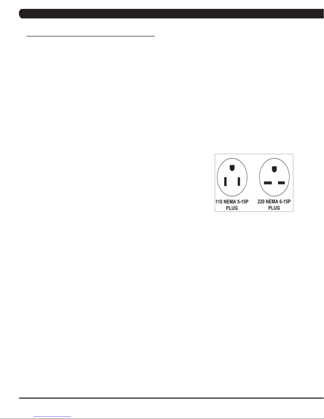
110 V UNITS
All Matrix 3x, 5x, 7xe and 7xi 110 V Climbmills require the use of a 100-125 V, 60 Hz and a 15 A
“Dedicated Circuit”, with a non-looped (isolated) neutral/ground for power. This outlet should be a
NEMA 5-15R and have the same configuration as the plug. No adapter should be used with this
product. These bikes can be daisy-chained together with up to 4 units per 15 A dedicated circuit.
Matrix daisy-chain cord adapters are sold separately.
220 V UNITS
All Matrix 3x, 5x, 7xe and 7xi 220 V Climbmills require the use of a 216-250 V, 50 Hz and a 15 A
“Dedicated Circuit”, with a non-looped (isolated) neutral/ground for power. This outlet should be a
NEMA 6-15R and have the same configuration as the plug. No adapter should be used with this
product. These bikes can be daisy-chained together with up to 4 units per 15 A dedicated circuit.
Matrix daisy-chain cord adapters are sold separately.
GROUNDING INSTRUCTIONS
The unit must be grounded. If it should malfunction or breakdown, grounding provides a path of least resistance for electric current to reduce the
risk of electric shock. The unit is equipped with a cord having an equipment-grounding conductor and a grounding plug. The plug must be plugged
into an appropriate outlet that is properly installed and grounded in accordance with all local codes and ordinances. If the user does not follow
these grounding instructions, the user could void the Matrix limited warranty.
ADDITIONAL ELECTRICAL INFO
In addition to the dedicated circuit requirement, the proper gauge wire must be used from the circuit breaker box, to each outlet that will have the
maximum number of units running off of it. If the distance from the circuit breaker box to each outlet, is 100 ft (30.5 m) or less, then 12 gauge wire
should be used. For distances greater than 100 ft (30.5 m) from the circuit breaker box to the outlet, a 10 gauge wire should be used.
ENERGY SAVING / LOW- POWER MODE
All units are configured with the ability to enter into an energy saving / low-power mode when the unit has not been in use for a specified period
of time. Additional time may be required to fully reactivate this unit once it has entered the low-power mode. This energy saving feature may be
enabled or disabled from within the ‘Manager Mode’ or ‘Engineering Mode.
North American power cord plugs shown.
Depending on your country, the plug type may vary.
ADD-ON PCTV
1.2 A of current (either from 110 V or 220 V). No more than 12 PCTVs should be used for each 15 A circuit and no more than 16 PCTVs
shoaaaaaauld be used for each 20 A circuit. The power outlet should have the same conguration as the plug. No adapter should be used with this
product. An RG6 coaxial cable with ‘F Type’ compression ttings will need to be connected between the video source and each add-on PCTV unit.
ADD-ON DIGITAL TV
Additional power requirements are not needed for the add-on digital TV. An RG6 coaxial cable with ‘F Type’ compression ttings will need to be
ttings will need to be connected between the video source and each add-on digital TV unit.
4
Page 8
CHAPTER 2: IMPORTANT SAFETY INSTRUCTIONS
2.3 LOCATING THE UNIT
LOCATION OF THE UNIT
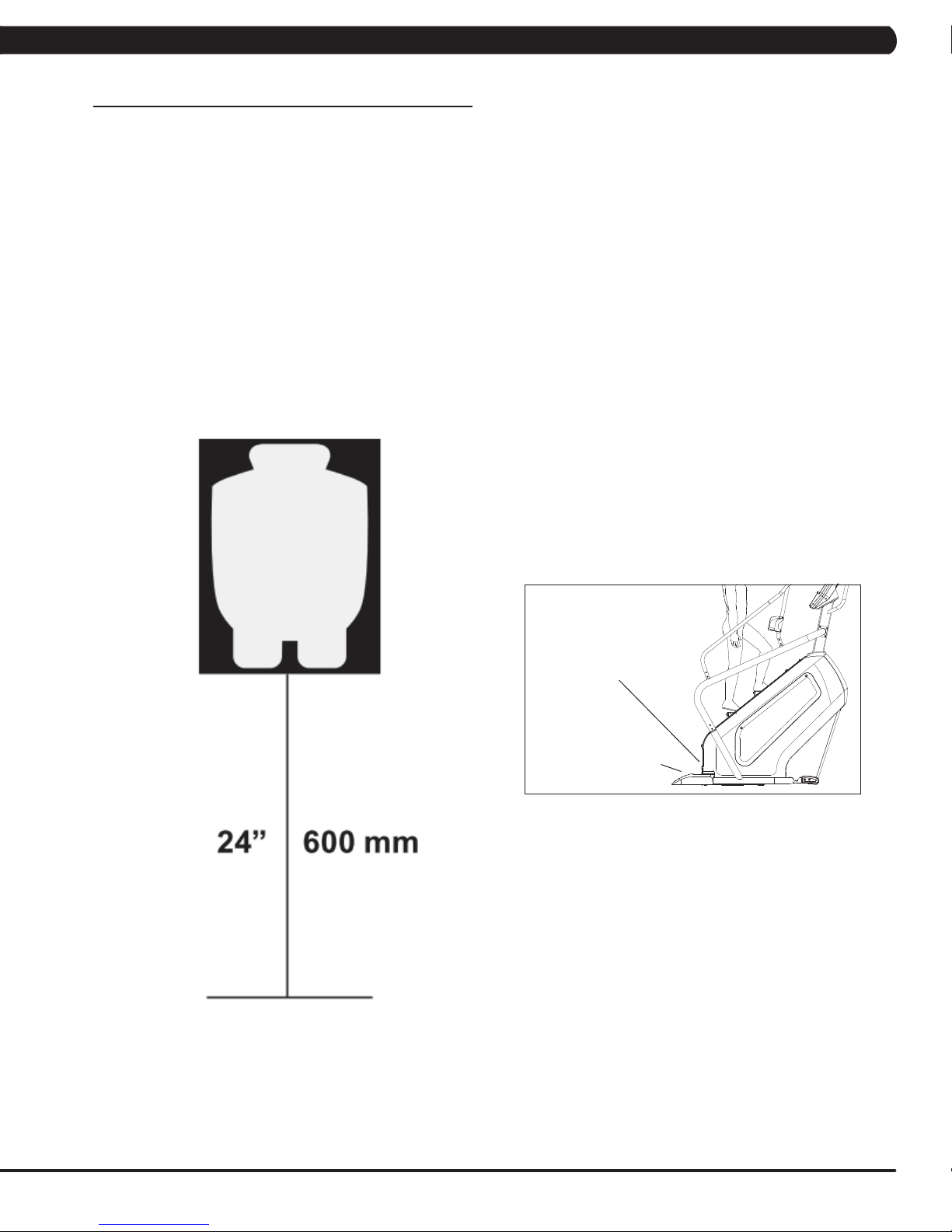
Place the unit on a level surface and away from direct sun light. The intense UV light can cause discoloration of plastics. Locate in an area
with cool temperatures and low humidity. Leave a clear zone behind the unit of at least 24". This zone must be clear of any obstruction and
allow the user a clear exit path from the unit. Do not place the unit in any area that will block the openings or vents. The unit should not be
used in a garage or covered patio.
LEVELING THE UNIT
Locate a level, stable surface to position the equipment. The equipment has levelers located below the bottom step. To access
the levelers, remove the end caps (C3X) or CONTROL ZONE (C5X, C7XE and C7XI). CAUTION: There is an electrical plug
located under the CONTROL ZONE and will need to be unplugged before the cover can be completely removed. Use an allen
wrench to level the unit. Once stable, replace parts as they were removed.
HEIGHT REQUIREMENTS
The Climb Mill adds 30" - 38" (76 - 96cm) to a user's height. For example, a 6' (183cm) tall user will be 7'8" (234.4cm - 254.4cm) off the floor.
Total height of the user on the Climb Mill should not exceed 9'10" (300 cm), which means that users taller than 6'8" (204cm) should not use this
equipment.
AUTO STOP
SENSOR
CONTROL ZONE
(C5X, C7XE, C7XI)
5
Page 9
CHAPTER 3: PREVENTATIVE MAINTENANCE
3.1 RECOMMENDED CLEANING TIPS
In order to maximize life span, and minimize down time, all Matrix Fitness Equipment requires regularly
scheduled cleaning.
YOU WILL NEED:
- Mild dish soap and water mixture in a spray bottle (10:1 water to soap ratio).
- Lint free 100% cotton cleaning cloths or Micro fiber cleaning cloths.
- Vacuum / Shop Vac with extendable hose and soft brush attachment.
- Super Lube Multi Purpose Synthetic Lubricant with Syncolon® (PTFE) Aerosol - www.super-lube.com/sythetic-aerosol-spray-ezp-46.html.
- Corrosion Block (available from Matrix - part # ZMS4001374).
Gym wipes are okay for customers to use as they will not leave over spray on your product yet will clean & disinfect.
The soap / water and vinegar / water solutions recommended above are okay to leave on your floor for customers to use. NOTE: Vinegar is a
natural and safe disinfectant that will not cause corrosion.
We recommend that you do NOT allow customers to use spray bottles with chemical solutions to clean the equipment. If the cleaner is sprayed
directly on the equipment or overspray is present, it may cause your equipment to rust and / or cause damage to console overlays.
WEEKLY:
1. With a clean dry 100% lint free cloth and water / soap mixture, wipe down the entire frame including the stairs so it is free of dust, dirt, and
sweat.
2. With a clean dry 100% lint free cloth and water / soap mixture, wipe down the entire console area including the hand grips and hand rails.
MONTHLY:
1. Vacuum under and around the Climb Mill If you need to move the unit, unplug it first. Make sure to reset the casters after moving the unit
back into position to stabilize the unit.
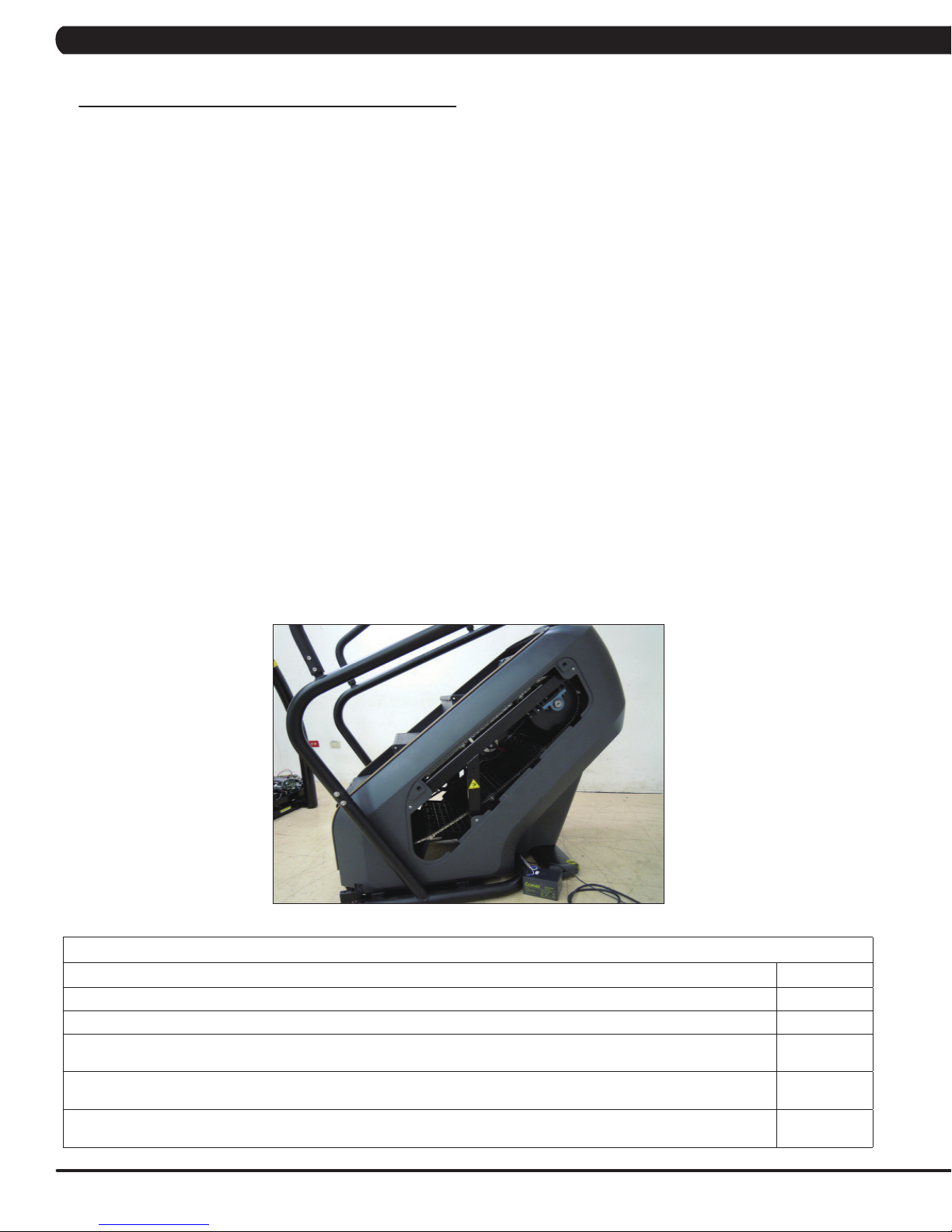
QUARTERLY:
1. Remove the side access panels and vacuum out the inside of the unit (Figure B).
2. Unplug the Climbmill and clean the AUTO STOP SENSORS (located under the bottom step) sensor with a cotton swab and rubbing alcohol.
FIGURE B
MAINTENANCE SCHEDULE
ACTION FREQUENCY
Check step motion and stability to ensure the Climbmill does not rock or wobble. QUARTERLY
Check all connecting joint areas for tightness of bolt assemblies. QUARTERLY
Ensure that there is little, or no free play at all joint assemblies once bolts have been tightened. Installation of washer kits may
be required if free play does not come out from tightening bolts.
Unplug the Climbmill and remove the access panel. Clean sprockets of old grease and re-apply a lithium-based grease to
sprocket teeth.
Unplug the Climbmill and clean the AUTO STOP SENSORS (located under the bottom step) with a cotton swab and rubbing
alcohol.
QUARTERLY
QUARTERLY
QUARTERLY
6
Page 10
CHAPTER 3: PREVENTATIVE MAINTENANCE
3.2 CARE AND MAINTENANCE INSTRUCTION
In order to maximize life span, and minimize down time, all MATRIX equipment requires regular cleaning, and maintenance items performed on
a scheduled basis. This section contains detailed instructions on how to perform these items, the frequency of which they should be done, and a
check list to sign off each time service is completed for a specific machine. Some basic tools and supplies will be necessary to perform these tasks
which include (but may not be limited to):
* Metric Allen wrenches
* #2 Phillips head screwdriver
* Adjustable wrench
* Teflon based spray lubricant such as “Super Lube”, or other Matrix approved product
* Lithium-based grease
You may periodically see addendums to this document, as the Matrix Technical Support Team identifies items that require specific attention, the
latest version will always be available on the Matrix website, www.matrixfitness.com
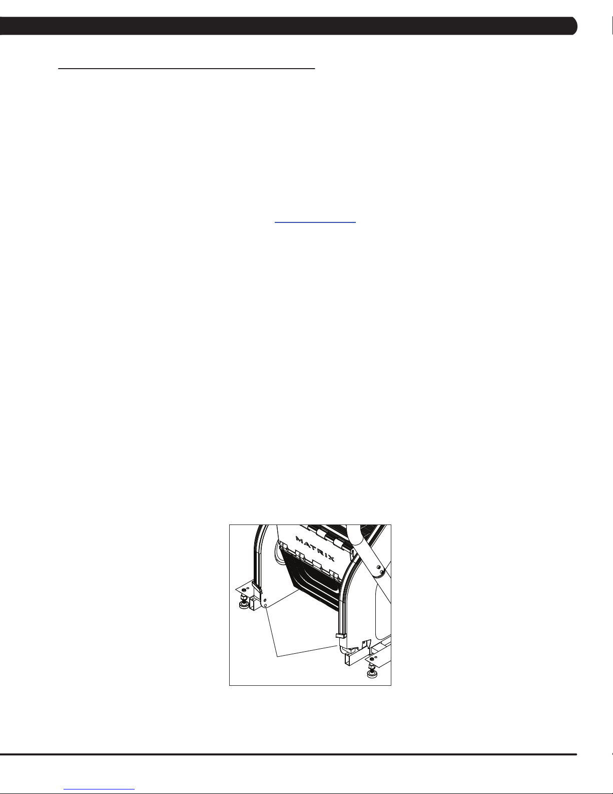
DAILY MAINTENANCE ITEMS
1. Attempt to wobble the unit from side to side and front to back. Level the unit if needed (See Section 10.4).
MONTHLY MAINTENANCE ITEMS
1. Check all connecting joint areas for tightness of fastened assemblies.
2. Remove the maintenance cover and clean and grease the drive chains using lithium-based grease.
QUARTERLY MAINTENANCE ITEMS
1. Check all connecting joint areas for tightness of fastened assemblies.
2. Check step motion and stability to ensure the Climbmill does not rock or wobble.
3. Remove the maintenance covers and check the brake for function.
4. Remove the maintenance cover and check the fans for function. Also clean and remove any debris from the digital speed sensor.
5. Remove the maintenance cover and check the chains for damage, alignment and proper tension.
6. Clean sprockets of old grease and re-apply a lithium-based grease to sprocket teeth.
7. On units with a AUTO STOP SENSORS, check to ensure the AUTO STOP SENSORS is working properly by walking on the unit, then Put your
foot in the middle of the IR sensors (transmission & receiver) to test the sensors are working and enough to stop machine.
8. Unplug the Climbmill and clean the AUTO STOP SENSORS (located under the bottom step) with a cotton swab and rubbing alcohol.
AUTO STOP
SENSORS
7
Page 11
CHAPTER 4: CONSOLE OVERLAY AND WORKOUT DESCRIPTION
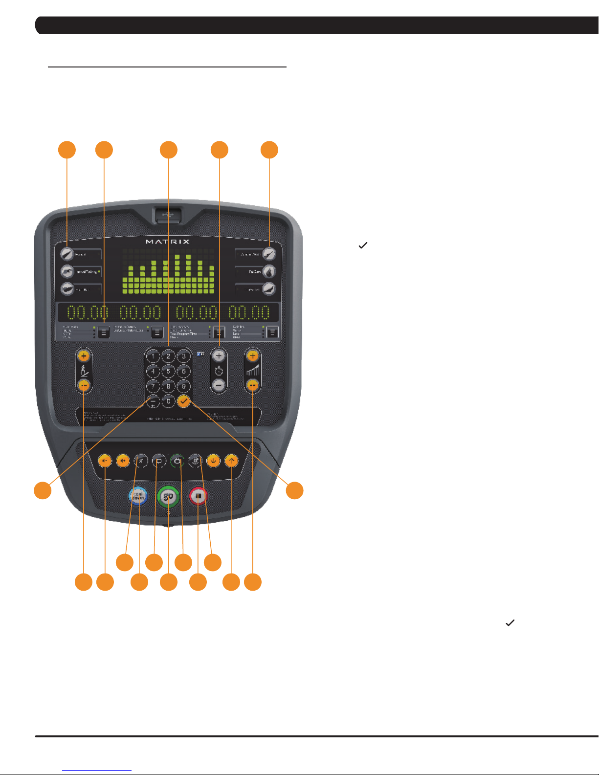
4.1 CONSOLE DESCRIPTION
e.g. A3X CONSOLE SHOWN
A
3X CONSOLE DESCRIPTION
AE HK
The Matrix machine is inspected before it is packaged. It is shipped in
two pieces: the base and the console. Carefully unpack the unit and
dispose of the box material. Note: There is a thin protective sheet of
clear plastic on the overlay of the console that should be removed
before use.
A) WORKOUT KEYS: Simple program view and selection buttons.
B) GO: One Touch Start.
C) ENTER
D) BACK: Go to previous program setting.
E) NUMBER KEYPAD: Enter program settings.
F) UP/DOWN LEVEL: Adjust resistance level.
G) UP/DOWN INCLINE (A3X ONLY): Adjust incline level.
H) UP/DOWN TIME: Adjust workout time.
I) STOP: Ends workout and shows workout summary data.
J) COOL DOWN: Puts the console into Cool Down mode.
: Confirm each program setting.
D C
N
O L
G
J
B
Q
I
FPM
K) TOGGLE DISPLAY: Cycles between 3 or 4 rows of workout
information displayed in LED window. The console will
automatically cycle between the workout information if the
Toggle Display button is pushed and held down for 3 seconds.
ENTERTAINMENT BUTTONS
L) TV POWER: Turns connected TV on or off.
M) VOLUME UP/DOWN: Adjusts the volume output through
headphones.
N) MUTE: Mutes sound.
O) CC: Turns closed captioning on or off.
P) CHANNEL UP/DOWN: Change channels on the integrated
console TV.
Q) LAST CHANNEL: Cycle between the current channel and the
previous channel.
E) NUMBER KEYPAD: Enter channel number. Press
confirm channel number.
to
8
Page 12

CHAPTER 4: CONSOLE OVERLAY AND WORKOUT DESCRIPTION
4.2 WORKOUT SETUP STEPS - MANUAL
Go - Press to immediately begin a workout. Workout, resistance
level, and time will automatically go to default settings. Pressing
GO will not prompt user for age, weight, or level settings.
1) Start pedaling and press the GO key to begin your workout. 2)
The display will read 3, 2, 1, Begin and then the program will start.
manual - Manual allows the user to input more information
while defining their own workout. Calorie expenditure will be more
accurate when inputting information in Manual than by pressing GO.
1) Start pedaling, press the MANUAL key. Then press ENTER.
2) Select Level by using the UP or DOWN LEVEL keys and press
ENTER.
3) Select Time by using the UP or DOWN LEVEL keys and press
ENTER.
4) Select Weight by using the UP or DOWN LEVEL keys and press
ENTER.
5) Press GO, and then the display will read 3, 2, 1, Begin and then
the program will start.
4.3 WORKOUT SETUP STEPS - LEVEL BASED PROGRAMS
Fat burn - Fat burn is a level based program that is designed
to help users burn fat through various resistance level changes.
4.3 WORKOUT SETUP STEPS - LEVEL BASED PROGRAMS
- CONTINUED
interVal traininG - The Interval Training program is a
level based program that automatically adjusts the resistance of the
machine from low to high intensity settings at regular intervals.
1) Start pedaling and press the Training Workouts. Then press
ENTER.
2) Select Intervals by using the UP or DOWN LEVEL keys and
press ENTER.
3) Select Level by using the UP or DOWN LEVEL keys and press
ENTER.
4) Select Time by using the UP or DOWN LEVEL keys and press
ENTER.
5) Select Weight by using the UP or DOWN LEVEL keys and press
ENTER.
6) Press GO then the display will read 3, 2, 1, Begin and then the
program will start.
1) Start pedaling and press the Training Workouts. Then press
ENTER.
2) Select FAT BURN by using the UP or DOWN LEVEL keys and
press ENTER.
3) Select Level by using the UP or DOWN LEVEL keys and press
ENTER.
4) Select Time by using the UP or DOWN LEVEL keys and press
ENTER.
5) Select Weight by using the UP or DOWN LEVEL keys and press
ENTER.
6) Press GO, then the display will read 3, 2, 1, Begin and then the
program will start.
9
Page 13
CHAPTER 4: CONSOLE OVERLAY AND WORKOUT DESCRIPTION
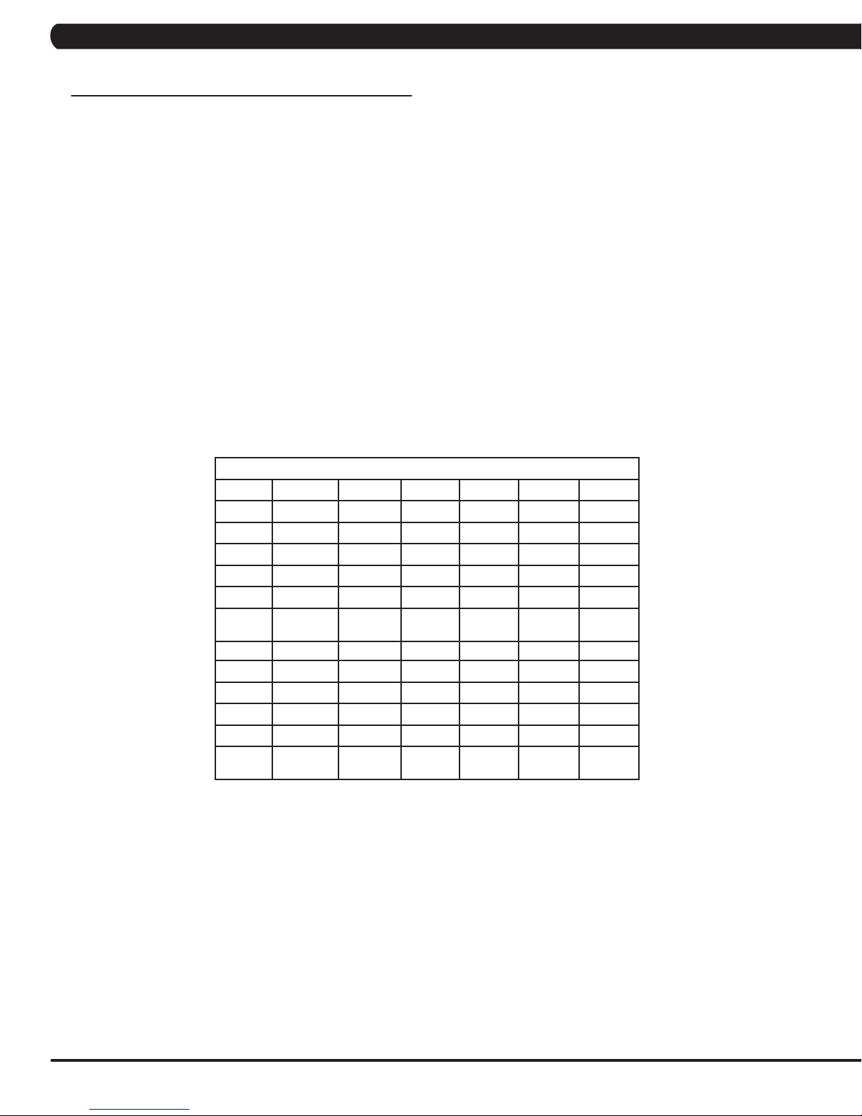
4.4 WORKOUT SETUP STEPS - FITNESS TEST
FITNESSTEST(WFI) - The WFI (Wellness Fitness Initiative) protocol is a test used by firefighters in a series of intervals lasting a
maximum of 16 minutes, where the speed is increased every minute until the Target Heart Rate is exceeded for 15 seconds. When the test
is complete, the display provides a summary of VO2max, Highest SPM, Elapsed Time, and Target Heart Rate. The test requires constant
monitoring of the user's heart rate, so the use of a telemetric heart rate strap is highly recommended.
CPat
The Candidate Physical Ability Test (CPAT) is a new minimum requirement for the position of Firefighter. The job of a Firefighter is one of
the most physically demanding jobs in North America. Participants wear a 50-pound (22.68-kg) vest to simulate the weight of self-contained
breathing apparatus (SCBA) and firefighter protective clothing. An additional 25 pounds (11.34 kg), using two 12.5-pound (5.67-kg) weights that
simulate a high-rise pack (hose bundle), is added to your shoulders for the stair climb event. The candidate must maintain 60 SPM (steps per
minute) for 3 minutes.
FITNESSTEST(SUBMAXIMAL)- The Submaximal test measures cardiovascular fitness and provides an estimated Sub-maximal
VO2 max result. This assessment is a 4 stage test lasting 3-5 minutes where the speed is increased until your Heart Rate is between 115 - 150
bpm for 2 of the stages. When the test is complete, a Fitness Rating is displayed as High, Good, Average, Fair, or Low along with your age and
VO2 max. The test requires constant monitoring of the user's heart rate, so the use of a telemetric heart rate strap is highly recommended.
1) Start pedaling and press the FITNESS TEST key. Then press ENTER.
2) Select Age by using the UP or DOWN LEVEL keys and press ENTER.
3) Select Gender by using the UP or DOWN LEVEL keys and press ENTER.
4) Select Weight by using the UP or DOWN LEVEL keys and press ENTER.
5) Press GO, then the display will read 3, 2, 1, Begin and then the program will start.
6) Once the workout is complete, the display will read the results of the Fitness Test.
FITNESS RATING NORMS (V02 MAX)
AGE 20-29 30-39 40-49 50-59 60+
MEN
HIGH 51.4+ 50.4+ 48.2+ 45.3 42.5+
GOOD 51.3-46.8 50.3-44.6 48.1-41.8 45.2-38.5 42.4-35.3
AVERAGE 46.7-42.5 44.5-41.0 41.7-38.1 38.4-35.2 35.2-31.8
FAIR 42.4-39.5 40.9-37.4 38.0-35.1 35.1-32.3 31.7-28.7
LOW 39.4 OR
LESS
WOMEN
HIGH 44.2+ 41.0+ 39.5+ 35.2+ 35.2
GOOD 44.1-38.1 40.9-36.7 39.4-33.8 35.1-30.9 35.1-29.4
AVERAGE 38.0-35.2 36.6-33.8 33.7-30.9 30.8-28.2 29.3-25.8
FAIR 35.1-32.3 33.7-30.5 30.8-28.3 28.1-25.5 25.7-23.8
LOW 32.2 OR
LESS
37.3 OR
LESS
30.4 OR
LESS
35.0 OR
LESS
28.2 OR
LESS
32.2 OR
LESS
25.4 OR
LESS
28.6 OR
LESS
23.7 OR
LESS
10
Page 14
CHAPTER 4: CONSOLE OVERLAY AND WORKOUT DESCRIPTION
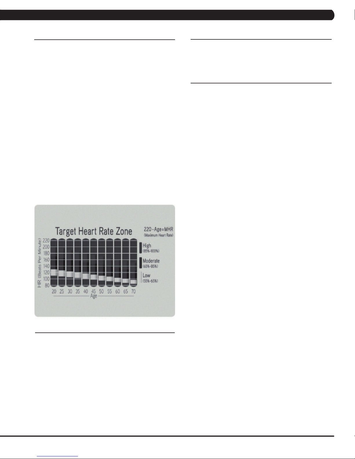
4.5 WORKOUT SETUP STEPS - TARGET HEART RATE
tarGet Heart rate - The Matrix H5x-05 Bike comes with
standard digital contact heart rate sensors and are POLAR telemetry
compatible. The heart rate control workout mode allows the user to
program their desired heart rate zone, and the bike will automatically
adjust the level based upon the user's heart rate. The heart rate
zone is calculated using the following equation: (220-Age)8%=target
heart rate zone. The user must wear a POLAR telemetric strap or
continually hold onto the contact heart rate grips for this workout.
Locate the metal sensors on the handlebars of the bike. Notice
that there are two separate pieces of metal on each grip. You must
be making contact with both pieces of each grip to get an accurate
heart rate reading. You can grab these sensors in any program to
view your current heart rate.
1) Start pedaling and press the HEART RATE key. Then press
ENTER.
2) Select Age by using the UP or DOWN LEVEL keys and press
SELECT.
3) Select Target HR Percentage by using the UP or DOWN LEVEL
keys and press SELECT.
4) Select Time by using the UP or DOWN LEVEL keys and press
SELECT.
5) Select Weight by using the UP or DOWN LEVEL keys and press
SELECT.
6) Press GO, then the display will read 3, 2, 1, Begin and the
program will start.
4.7 WORKOUT TRACKING INSTRUCTIONS
3x consoles equipped with xID workout tracking allow users to
login and record their workouts by entering their xID and 4-digit
passcode.
4.8 USB CHARGING INSTRUCTIONS
The USB port on the 3x console now supports device charging.
4.6 WORKOUT SETUP STEPS - CONSTANT WATTS
CONSTANTWATTS - Constant Watts is a unique program
that allows you to vary your cadence or RPM and the bike's
resistance level will adjust accordingly to your selected goal. The
quicker you pedal, the less resistance for the goal selected.
1) Start pedaling and press the CONSTANT WATTS key. Then
press ENTER.
2) Select Watts by using the UP or DOWN LEVEL keys and press
SELECT.
3) Select Time by using the UP or DOWN LEVEL keys and press
SELECT.
4) Select Weight by using the UP or DOWN LEVEL keys and
press SELECT.
5) Press GO, then the display will read 3, 2, 1, Begin and the
program will start.
11
Page 15
CHAPTER 5: MANAGER MODE
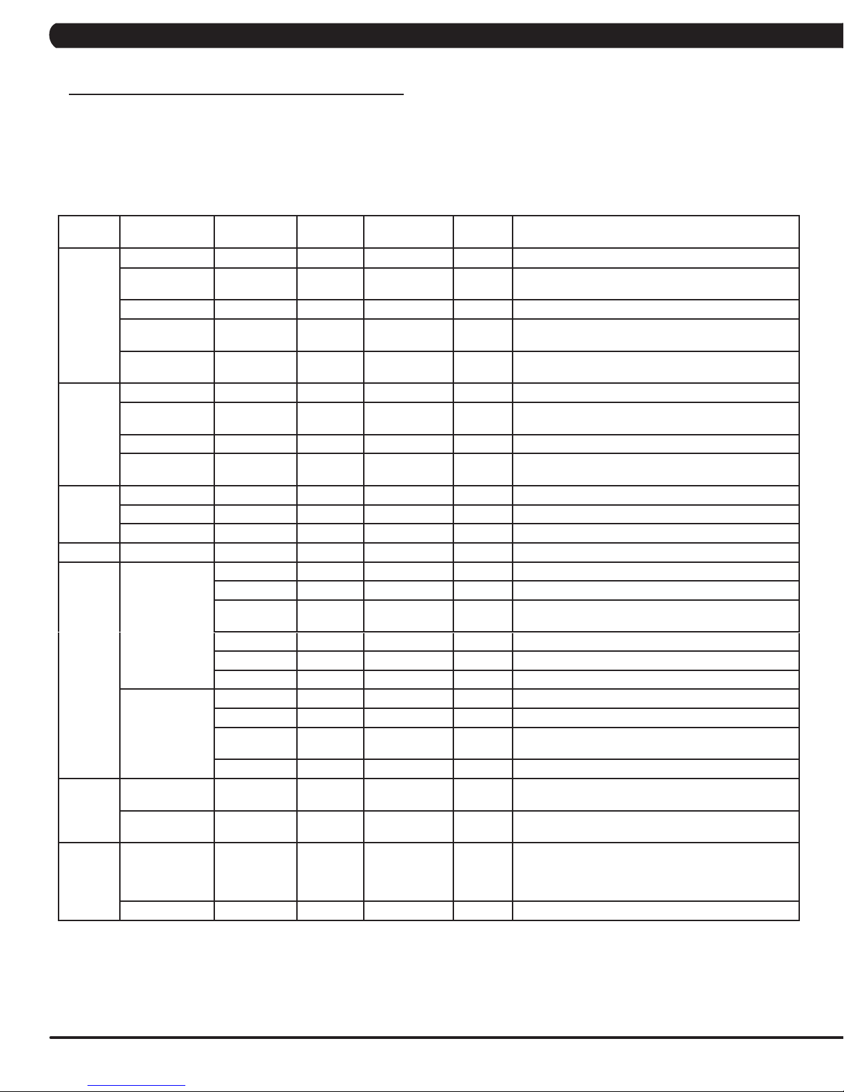
5.1 MANAGER MODE OVERVIEW
1) To enter Manager Mode, press number key "ENTER, 1, 0, 0, 1, ENTER" on the number keypad. Manager Mode will appear on the display.
2) To scroll through the list of options in Manager Mode, use the UP and DOWN LEVEL keys. Each of the custom settings will show on the display.
3) To select a custom setting, press the ENTER key when the desired setting is shown.
4) To change the value of the setting, use the UP and DOWN LEVEL keys.
5) To confirm and save the value of the setting, press the ENTER key.
6) To exit the setting without saving, press the BACK key.
7) Press and hold the STOP key for 3-5 seconds to return to normal operation.
Group Item1 Item2 Default
Workouts Maximum Time 60 4~99 Minutes Sets the total run time of any program.
Default Time 20 4~MAX Minutes Workout time when GO is pressed or when no time is
Maximum Level 20 10~25 Set the level which is the max usable speed.
Default Level 1 1~10 Starting resistance when GO is pressed or when no
Pause Time 5:00 0:30/1:00/2:00/
User Default Age 30 10-100 This option controls the default user's age.
Default Weight 150lb/
Default Height 72/ 83 36/91~96/244 Default height of user.
Gender Male Male/Femal Determines the gender of the user when not selected
Data &
Time
Speed Unit Standard Standard/Metric This option sets speed unit is standard (Mile) or Metric.
Software Version UCB Current software version of UCB.
General Accumulate
Language Default
Data This option sets the current date of the machine.
Time RTC time This option sets the current time of the machine.
Time Zone 21 1~78 This option sets the time zone.
LCB-MCUB Current software version of LCB-MCUB.
LCB-MCUA
(option)
Language Sets the language for the console.
WiFi Current software version of WiFi.
Bootloader Current software version of bootloader.
Update UCB UCB software update.
LCB-MCUB LCB-MCUB software update.
LCB-MCUA
(option)
Language Language software update.
Time
Accumulate
Floors
Language
Erase EEPROM Erase language data in EEPROM.
Value
68kg
0 0~999999 Hours Total time for all programs displayed in hours.
0 0~999999 Floors Total floors for all programs.
Values/Range Unit Notes
selected during program set up.
resistance is selected during program set up.
3:00/4:00/5:00
50lb/23kg ~
400lb/182kg
English Sets the language for the console. Select between
Minutes :
Second
This option controls the default pause time.
This option controls the default weight.
during program set up.
Current software version of LCB-MCUA.
LCB-MCUA software update.
English, Spanish, German, Italian,
French, Dutch, Portuguese Swedish, Finnish, Turkish
and Polish.
12
Page 16

CHAPTER 5: MANAGER MODE
5.1 MANAGER MODE OVERVIEW - CONTINUED
Group Item1 Item2 Default Value Values/Range Unit Notes
Logo Default Logo MATRIX Customize.
Import Logo Import logo from USB to console.
Erase EEPROM Erase all logo data in EEPROM.
Machine Type This option selects the current model.
Serial Number
Out of Order OFF ON/OFF This option allows the club to show the unit
Speaker OFF ON/OFF Sets console speaker sound on / off.
Beeper ON ON/OFF Sets console beeper sound on / off.
Headphone Jack Notification Enable Enable/Disable This option controls the headphone Jack
USB Port Protection Enable Enable/Disable This option controls the USB port protection is
Keypad Stuck Check Enable Enable/Disable This option controls the keypad stuck check is
TV Power OFF ON/OFF OFF: Turn off TV power after reset
Input Source OFF OFF/TV/PCTV/
Default Channel 3 This option controls the default TV channel
Default Volume a. input default
Internet Enable/Disable Sets the internet function (WiFi) is disabled or
MAC ID MAC ID data.
IP Automatically detects the available IP address
Site Survey Club internet survey.
Export setting to
USB
Import setting
from USB
Reset Reset internet connected data. SSID/
ErP Erp Time OFF OFF~ 30(Minutes) Minute Console will enter ErP mode if user does not
Console Prefix+(Type)
Frame Prefix+(Type)
Times to
waring
Notification Enable Enable/Disable This option controls the Keypad/overlay error
+YYMM00000
+YYMM00000
30000 1000~1000000 This option controls the headphone Jack
YY-MM-xxxxx Serial Number input is available for both the
YY-MM-xxxxx
Remote TV/CAB
Console and Frame.
Type: B~Z (A not display).
"out of order" if an error is present.
insertion times warning function is disabled or
enabled.
insertion times warning function is
disabled or enabled.
disabled or enabled.
disabled or enabled.
notification is disabled or enabled.
ON: Don't turn off TV power after reset
Sets the audio of the console to the type of TV
attached.
on start up.
(DF: 15/Range1~15)
b. Max
(DF: 32/ Range: 1~32)
c. Output Default
(DF: 13/Range:1~Max)
Remote TV support a/b/c item, others only
support c.
enabled.
and displays it.
Export internet setting (Wifi) to USB.
Import internet (Wifi) setting from USB.
password Factory Default Restore.
touch the screen or press any key pad for
couple minutes.
13
Page 17
CHAPTER 6: ENGINEERING MODE
6.1 ENGINEERING MODE OVERVIEW
1) To enter Engineering Mode, press number key "ENTER, 2, 0, 0, 1, ENTER" on the number keypad. Engineer Mode will appear on the
display.
2) To scroll through the list of options in Engineering Mode, use the UP and DOWN LEVEL keys. Each of the custom settings will show on the
display.
3) To select a custom setting, press the ENTER key when the desired setting is shown.
4) To change the value of the setting, use the UP and DOWN LEVEL keys.
5) To confirm and save the value of the setting, press the ENTER key.
6) To exit the setting without saving, press the BACK key.
7) Press and hold the STOP key for 3-5 seconds to return to normal operation.
Group Item1 Item2 Default
Value
Error Codes Disable/Enable Enable Disable/Enable This option displays the error code history on
DAPI Server Production Dev/QA/Staging/
Safety Setting 100 4~500 The acting speed adjusted of old control zone
Switch ON->5X,
OFF->3X
Values/Range Unit Notes
the unit.
Production
ON/OFF The function of control zone is enabled or
Minutes :
Second
Dev
unsecure domain: dev.dls.jfit.co port: 80
SSL domain: dev-dls.jfit.co port: 443
QA
unsecure domain: qa.dls.jfit.co port: 80
SSL domain: qa-dls.jfit.co port 443
Staging
unsecure domain: staging.dls.jfit.co port: 80
SSL domain: staging-dls.jfit.co port 443
Production
unsecure domain: dapi-ls.jfit.co port: 80
SSL domain: dapi-ls.jfit.co port: 443
(capacitance sensor).
disabled.
14
Page 18

CHAPTER 7: SERVICE MODE / TEST MODE
7.1 SERVICE MODE OVERVIEW
1) To enter Service Mode, press number key "ENTER, 3, 0, 0, 1, ENTER" on the number keypad. Engineer Mode will appear on the display.
2) To scroll through the list of options in Service Mode, use the UP and DOWN LEVEL keys. Each of the custom settings will show on the
display.
3) To select a custom setting, press the ENTER key when the desired setting is shown.
4) To change the value of the setting, use the UP and DOWN LEVEL keys.
5) To confirm and save the value of the setting, press the ENTER key.
6) To exit the setting without saving, press the BACK key.
7) Press and hold the STOP key for 3-5 seconds to return to normal operation.
Group Item1 Item2 Default Value Values/Range Unit Notes
Accumulate Floors Current value 0~999999 Manually sets the Accumulated
Time Current value 0~999999 Manually sets the Accumulated
Log Error Display None Error0~Error10
Reset Reset error log..
Headphone Jack
Sensor
Configuration Export to USB Export engineer parameters to a
Import from USB Import engineer parameters from a
Factory Default Reset NO NO-YES Reset engineering default
Asset management Disable/Enable Disable Disable/Enable This option controls the AM
Insert Counts Current Value 0~999999 Insert headphone jack counts..
Reset NO NO-YES Reset headphone insert counts.
/ None
Floors.
.
Time
Shows the last 10 errors.
USB device.
USB device.
to factory value.
function is Disabled or Enabled.
Club ID This option records the club ID of
xID Login Enable/Disable Disable Disable/Enable This option controls the xID login
the fitness facility.
function is Disabled or Enabled.
15
Page 19

CHAPTER 7: SERVICE MODE / TEST MODE
7.2 TEST MODE OVERVIEW
The Test's Custom Mode allows the club owner to customize the bike for the club.
1) To enter Test Mode, press number key "ENTER, 5, 0, 0, 1, ENTER" on the number keypad. Engineer Mode will appear on the display.
2) To scroll through the list of options in Test Mode, use the UP and DOWN LEVEL keys. Each of the custom settings will show on the display.
3) To select a custom setting, press the ENTER key when the desired setting is shown.
4) To change the value of the setting, use the UP and DOWN LEVEL keys.
5) To confirm and save the value of the setting, press the ENTER key.
6) To exit the setting without saving, press the BACK key.
7) Press and hold the STOP key for 3-5 seconds to return to normal operation.
Group Item1 Item2 Default Value Values/
Range
Display Press the ENTER key repeatedly to check
Keypad Press any key and the display should show
C-SAFE Press the ENTER key to test CSAFE.
Headphone Jack Press the ENTER key to insert headphone
RFID Test RFID hardware status when scan the ID
ErP AUTO/5/10/
30/50
Unit Notes
each set of LEDs on the display sequentially.
the corresponding message.
jack counts test.
tag.
Scond Erp testing only work in testing mode, it will
not save and not work when the console out
of testing mode.
Auto- the machine will enter Erp mode after
press the enter.
16
Page 20
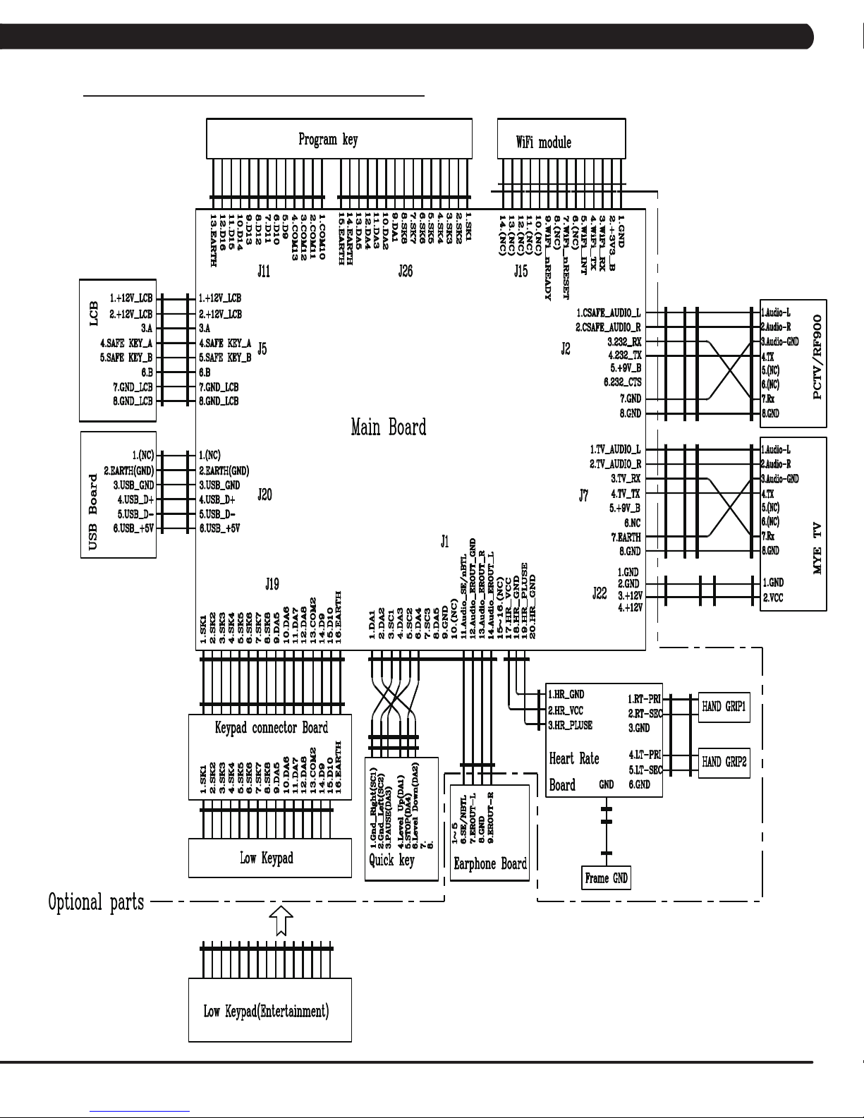
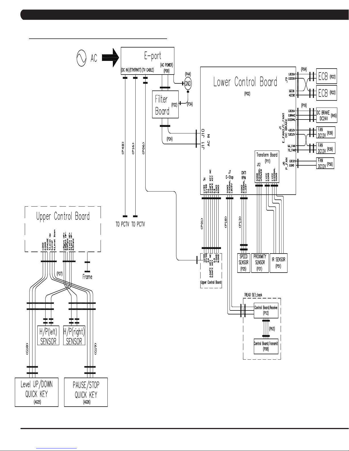
8.1 ELECTRICAL DIAGRAMS
CHAPTER 8: TROUBLESHOOTING
17
Page 21
CHAPTER 8: TROUBLESHOOTING
8.1 ELECTRICAL DIAGRAMS - CONTINUED
18
Page 22
CHAPTER 8: TROUBLESHOOTING
8.1 ELECTRICAL DIAGRAMS - CONTINUED
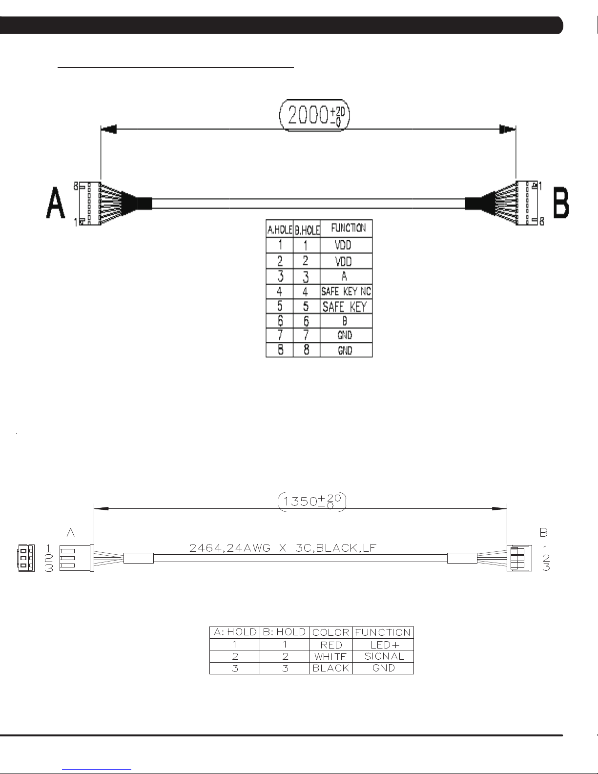
P01 - DIGITAL COMMUNICATION WIRE
P13- SPEED SENSOR EXTENSION WIRE (FRAME)
19
Page 23
CHAPTER 8: TROUBLESHOOTING
8.1 ELECTRICAL DIAGRAMS - CONTINUED
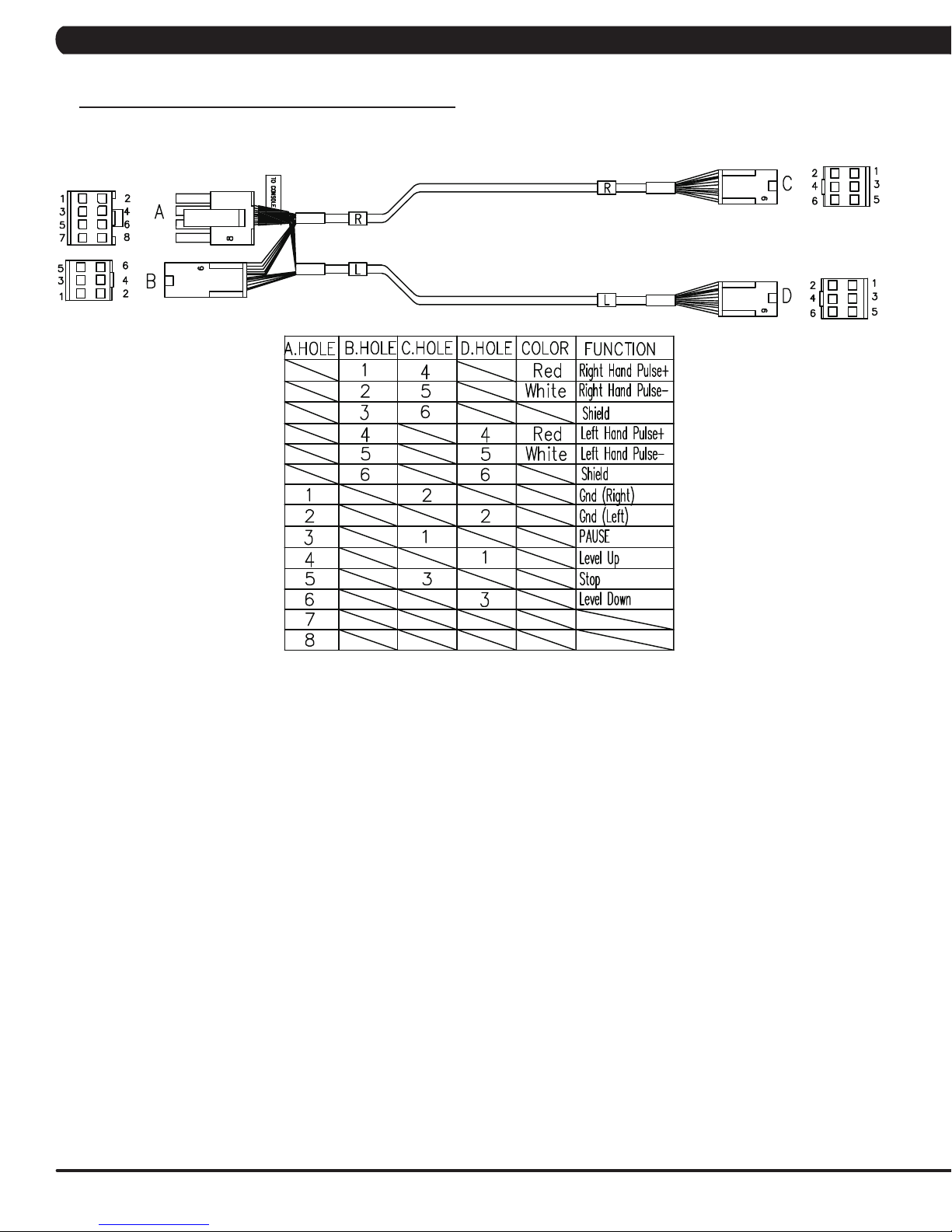
P27 - HAND PULSE WIRES (FRAME)
20
Page 24

CHAPTER 8: TROUBLESHOOTING
8.1 ELECTRICAL DIAGRAMS - CONTINUED
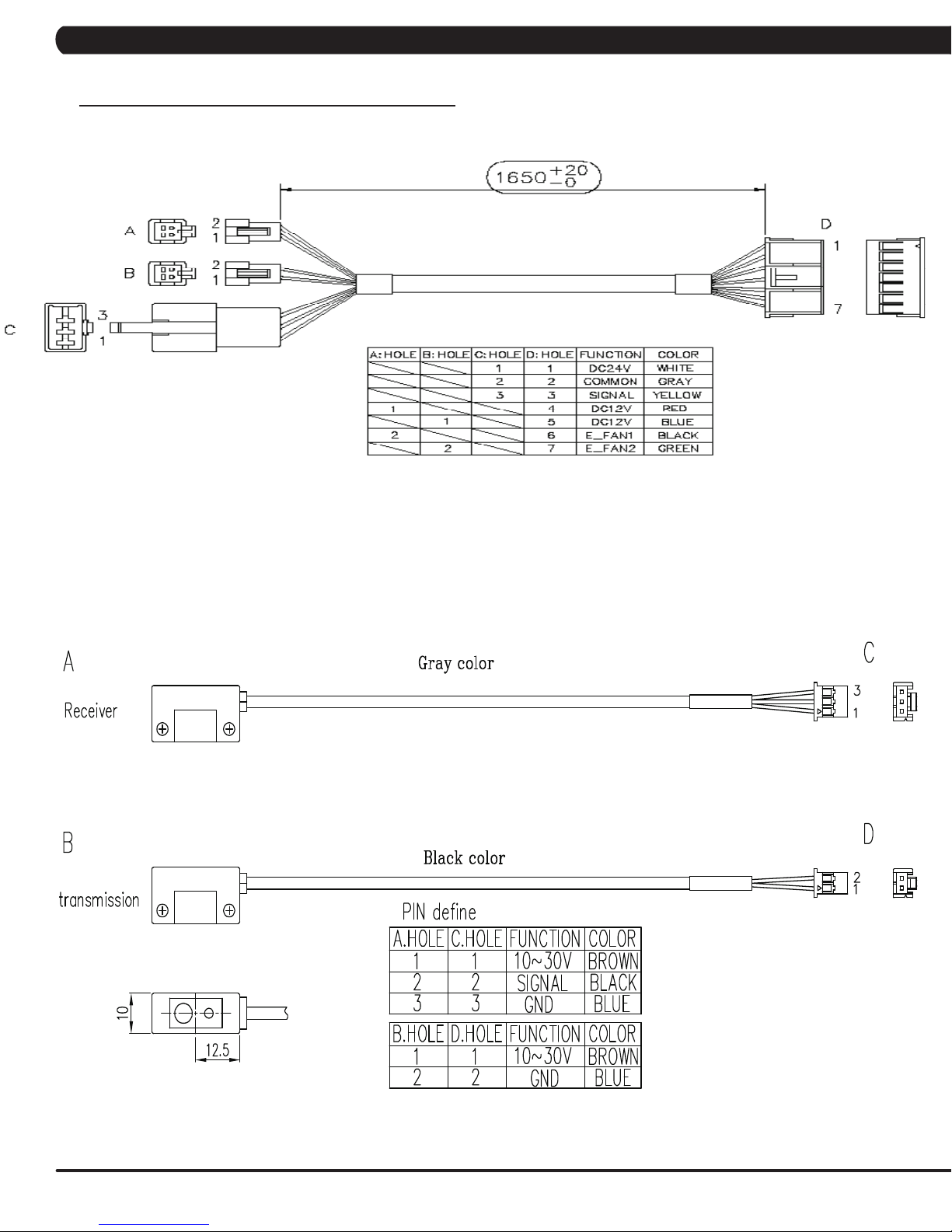
P31 - PROXIMITY SENSOR WIRE (FRAME)
P04 - ECB LOAD WIRE (FRAME)
P18 - CONTROL ZONE SENSOR WIRE
21
Page 25
CHAPTER 8: TROUBLESHOOTING
8.1 ELECTRICAL DIAGRAMS - CONTINUED
P19 - POWER SENSOR WIRE (FRAME)
P51 - IR SENSOR WIRE (FRAME)
22
Page 26
CHAPTER 8: TROUBLESHOOTING
8.1 ELECTRICAL DIAGRAMS - CONTINUED
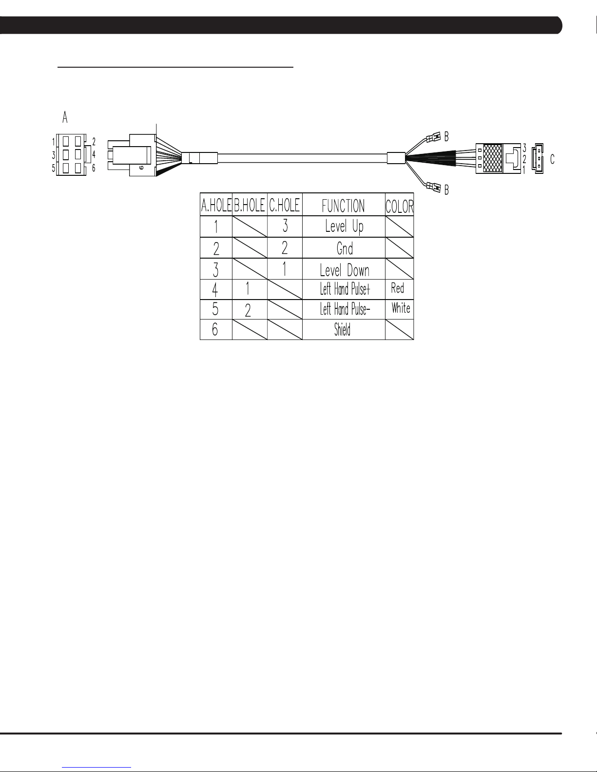
G18 - H/P CONNECT WIRE (FRAME)
23
Page 27
CHAPTER 8: TROUBLESHOOTING
8.1 ELECTRICAL DIAGRAMS - CONTINUED
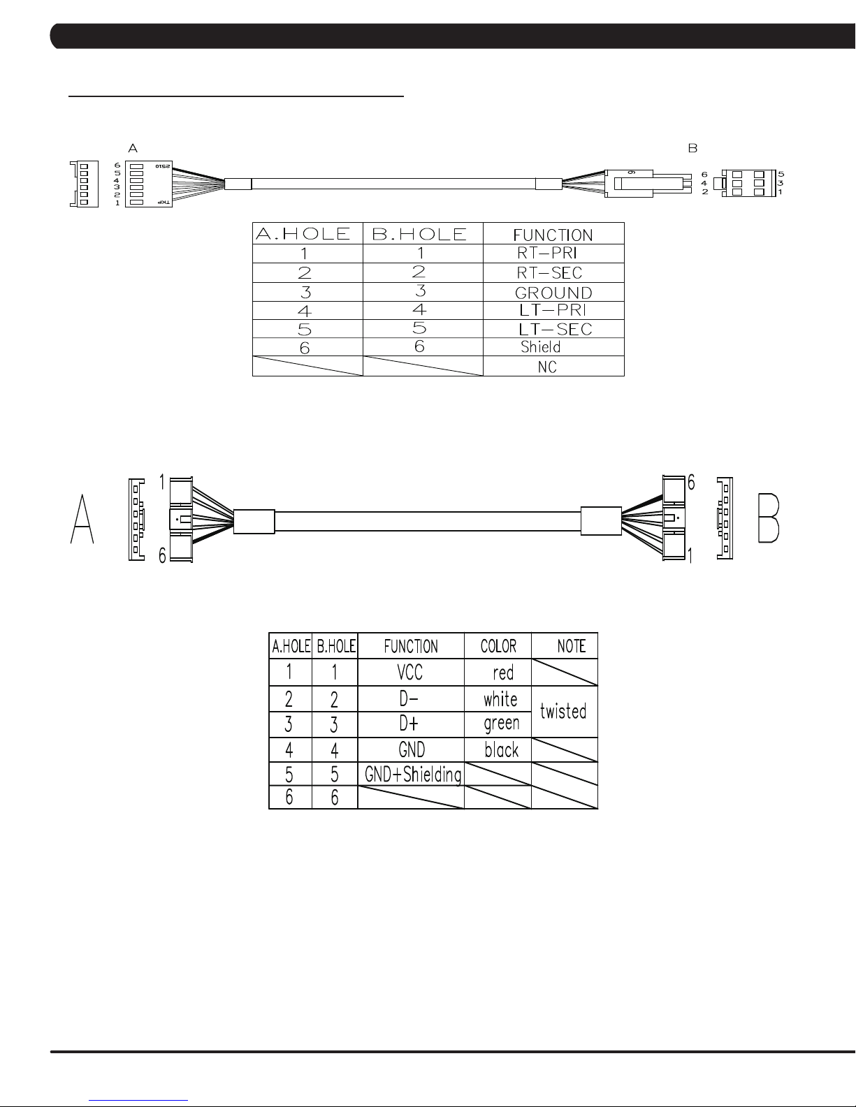
PAUSE SENSOR WIRE (CONSOLE)
USB WIRE (CONSOLE)
24
Page 28

CHAPTER 8: TROUBLESHOOTING
8.1 ELECTRICAL DIAGRAMS - CONTINUED
DIGITAL COMM WIRE (CONSOLE)
QUICKLY KEY WIRE (CONSOLE)
25
Page 29

8.2 LCB ERROR INDICATORS
CHAPTER 8: TROUBLESHOOTING
26
Page 30

CHAPTER 8: TROUBLESHOOTING
8.2 LCB ERROR INDICATORS - CONTINUED
Status LED
---------------------------------------------------------------------------------Firmware definition-----------------------------------------------------------------------------------
LED STATUS DESCRIPTION
LED1 LCB status (blinking: OK).
LED2 Start or Stop( bright: start )
LED3 Safety stop ( bright: action )
LED4 Safety Key action status ( bright: trigger )
LED5 LCB Error status
LED6 UCB and LCB connection status (blinking: OK)
--------------------------------------------------------------------------------
Hardware definition-----------------------------------------------------------------------------------
LED STATUS DESCRIPTION
LED7 MCU power lamp
LED8 Electro-magnet device 2 PWM lamp
LED9 Electro-magnet device 2 fan lamp
LED10 Electro-magnet device 1 PWM lamp
LED11 Electro-magnet device 1 fan lamp
LED12 DC brake release lamp
LED13 DC 26V lamp
D12 Safety switch power lamp
D35 RPM lamp
D8 Positioning sensor lamp
D15 DC 12V lamp
27
Page 31

CHAPTER 8: TROUBLESHOOTING
8.3 ERROR CODE TROUBLESHOOTING - 0149 (01AC)
ERROR CODE 0149 (01AC)
1) SYMPTOM:
a. 0149 (01AC) - Electro magnet (ECB) over current.
2) SOLUTION:
a. On standby mode, measure the resistance on ECB1 and ECB2. Check the ECB extension cable connection at the LCB (pins 1 & 3 for
ECB1, pins 2 & 4 for ECB2), there should be between 12.8 ~ 14.2 ohms. (Figure A)
- If the ECB resistance is out of the range, replace the ECB.
- If the ECB resistance is within the range, replace the LCB.
b. Check the gap of ECB1 and ECB2. There should be a gap of .5mm between the ECB and the flywheel.
- Adjust the gap as shown in Section 9.16.
FIGURE A
28
Page 32

CHAPTER 8: TROUBLESHOOTING
8.4 ERROR CODE TROUBLESHOOTING - 01AF
ERROR CODE 01AF
1) SYMPTOM:
a. 01AF - Electro magnet (ECB) disconnected.
2) SOLUTION:
a. Check the connection of the ECB extension cable from the LCB to the ECB (Figure A).
b. Check to see if LED8 and LED10 on the LCB have a brief light for 3 second when you power on machine.
- If LED8 and LED10 do not have a brief light, replace the LCB.
- If LED8 and LED10 do have a brief light, check the ECB extension cable connection at the LCB (pins 1 & 3 for ECB1, pins 2 & 4 for
ECB2), there should be between 12.8 ~ 14.2 ohms. (Figure B)
- If the ECB resistance is out of the range, replace the ECB.
- If the ECB resistance is within the range, replace the LCB.
c. Check the gap of ECB1 and ECB2 (Figure B). There should be a gap of .5mm between the ECB and the flywheel.
- Adjust the gap as shown in Section 9.16.
FIGURE A
FIGURE B
29
Page 33

CHAPTER 8: TROUBLESHOOTING
8.5 ERROR CODE TROUBLESHOOTING - 02A0
ERROR CODE 02A0
1) SYMPTOM:
a. 02A0 - Encoder error.
b. The unit is in PAUSE Mode at all times.
2) SOLUTION:
a. Check the connection of the speed sensor cable from the LCB to the speed sensor.
b. Check to see if LED D35 on the LCB is on when the brake is turned to the left release position (Figure A).
If LED D35 is off, move the stairs about 3 stairs and check to see if LED D35 is flashing.
- If not, replace the speed sensor.
- If yes, adjust the speed sensor position and clean the speed sensor of any debris (Figures B), then re-test.
FIGURE BFIGURE A
30
Page 34

CHAPTER 8: TROUBLESHOOTING
8.6 ERROR CODE TROUBLESHOOTING - 02BE / 02BF
ERROR CODE 02BE / 02BF
1) SYMPTOM:
a. 02BE - DC brake error (If movement is detected when the brake is in stop mode).
b. 02BF - DC brake over current (The brakes current is over 1A for a continuous 3 sec.).
2) SOLUTION:
a. Check the power extend wire connection between the brake and LCB for any damage (Figures A & B).
b. Check to see if the stairs will move when you are in the stop position. If yes, replace the brake.
FIGURE BFIGURE A
31
Page 35

CHAPTER 8: TROUBLESHOOTING
8.7 ERROR CODE TROUBLESHOOTING - 02CO
ERROR CODE 02C0
1) SYMPTOM:
a. 02C0 - DC brake in manual mode.
2) SOLUTION:
a. Check if the DC brake is in the “ Right “ lock position (Figure A). Release the brake (move to the left) if in lock position.
b. Replace the brake.
FIGURE A
32
Page 36

CHAPTER 8: TROUBLESHOOTING
8.8 ERROR CODE TROUBLESHOOTING - 02C1
ERROR CODE 02C1
1) SYMPTOM:
a. 02C1 -Speed tracking error (the speed tracking is off by at least 10 rpms for a continuous 20 sec).
2) SOLUTION:
a. Adjust the speed sensor position and clean the speed sensor of any debris (Figure A).
b. Check the ECB extension cable connection at the LCB (pins 1 & 3 for ECB1, pins 2 & 4 for ECB2), there should be between 12.8 ~ 14.2
ohms, check which ECB is outside the range and replace it (Figure B).
FIGURE A FIGURE B
33
Page 37

CHAPTER 8: TROUBLESHOOTING
8.9 ERROR CODE TROUBLESHOOTING - 02C3
ERROR CODE 02C3 (Frame IR transmitter Error)
1) SYMPTOM:
a. During power on, the frame IR receiver connector is disconnected.
b. During power on, the frame IR transmitter is no power or connector is disconnected.
c. During power on, the frame IR sensors are hidden for over 3 seconds.
2) SOLUTION:
a. Check if there's something blocking the control zone IR sensors. (Figure A).
b. Check if the frame IR sensors (transmitter and receiver) are aligned (Figure B).
c. Check the connection of the frame IR transmitter cable from the LCB to the frame IR transmitter sensors (Figure C & D).
d. Check if the frame IR transmitter cable is good. Replace it if the cable is defective (Figure C & D).
FIGURE A FIGURE B
FIGURE C FIGURE D
34
Page 38

CHAPTER 8: TROUBLESHOOTING
8.10 ERROR CODE TROUBLESHOOTING - 02C5
ERROR CODE 02C5 (Frame IR frequency error)
1) SYMPTOM:
The signal is abnormal over ten seconds..
2) SOLUTION:
Replace LCB set (part no.1000336916).
8.11 ERROR CODE TROUBLESHOOTING - 02C7
ERROR CODE 02C7 (Frame IR receiver disconnection)
1) SYMPTOM:
Receiver connector is disconnected over 3 seconds.
2) SOLUTION:
a. Check the connection of the frame IR receiver cable from the LCB to the frame IR receiver sensor (Figure A).
b. Check if LED1 on the small transfer board is bright (Figure B).
- If not, replace the LCB set (part no.1000336916).
- If yes, replace frame IR receiver cable.
FIGURE A FIGURE B
35
Page 39

CHAPTER 8: TROUBLESHOOTING
8.12 ERROR CODE TROUBLESHOOTING - 04A0
ERROR CODE 04A0
1) SYMPTOM:
a. 04A0 - Console has no communication or is disconnected.
2) SOLUTION:
a. Check the console cable connections at the LCB (Figure A) and UCB (Figure B).
b. Replace the console cable.
c. Replace the UCB.
FIGURE BFIGURE A
36
Page 40

CHAPTER 8: TROUBLESHOOTING
8.13 ERROR CODE TROUBLESHOOTING - 04B0
ERROR CODES 04B0
1) SYMPTOM:
a. 04B0 - LCB no communication response for over 3 seconds. .
2) SOLUTION:
a. Check the console cable connections at the LCB (Figure A) and UCB (Figure B).
b. Replace the console cable.
c. Replace the LCB.
FIGURE A FIGURE B
37
Page 41

CHAPTER 8: TROUBLESHOOTING
8.14 TROUBLESHOOTING - NO POWER TO THE CONSOLE
NO POWER TO THE CONSOLE
1) SYMPTOM:
a. The unit is not getting power from the outlet.
b. The LCB is not getting power from the power receptacle.
c & d. The LCB LEDs are lit, but there is no power to the console.
2) SOLUTION:
a. Remove the front disk and check to see if LED D15 is lit on the LCB. If it is not, verify power at the outlet. If the outlet is not outputting
120V, check the fitness room power.
- If LED 15 is still not lit after verifying the fitness room power, replace the power cord.
b. Check to see if LED D15 is lit on the LCB (Figure A).
- If LED D15 is not lit, check for incoming AC voltage at the LCB. Replace the power components as needed if the voltage is not
present.
- Replace the LCB if all power components are ok and there is AC voltage to the LCB.
c. Check the console cable for connection at the LCB and console (Figure B). Use a multi-meter to check console cable (pins 1 and 7 for
12V, pins 2 and 8 for 12V) - Figure B. There should be approximately 12V present. Replace the console cable if this reading is off.
d. If there is still no power, replace the console.
38
FIGURE BFIGURE A
Page 42

CHAPTER 8: TROUBLESHOOTING
8.15 TROUBLESHOOTING - HEART RATE ISSUES
HEART RATE ISSUES
1) SYMPTOM:
a. No heart rate.
b. Erratic or consistently high heart rate.
2) SOLUTION:
a. With a multi-meter set for DC Voltage, place one prong of the multi-meter on each of the heart rate plates on the handlebar (Figure A).
A correctly connected HR grip will have a DC Voltage reading of between .5 and 2.0VAC. Repeat this step on both HR grips. If this reading is
correct, skip to Step b. If not continue with Step a.
- Remove the screws holding the 2 halves of the HR grip together (Figure B).
FIGURE A
- Check the connection of the heart rate grip wiring to the grips (Figure C). Replace the HR grips if any damage is seen to the plates.
- Loosen the 6 handlebar screws on each side of the unit (Figure D).
FIGURE B
FIGURE DFIGURE C
39
Page 43

CHAPTER 8: TROUBLESHOOTING
8.15 TROUBLESHOOTING - HEART RATE ISSUES - CONTINUED
- Remove the 2 screws going into the handlebar connection frame from the bottom (Figure E).
- Remove the 3 screws going into the handlebar connection frame from the top (Figure F).
FIGURE FFIGURE E
- Pull the handlebars out of the handlebar connection frame, and disconnect the HR wiring on each side (Figure G).
- Remove the handlebar connection frame from the unit (Figure H).
- Perform a continuity test on the wiring going from the HR grip to the handlebar connection frame. With a multi-meter set for ohms,
place one prong on the HR grip wiring coming out of the handlebar (Figure I) and one prong on the HR plate. The HR wiring is red, black, and
white (match red with red and white with white). For example, the red wire on the left HR grip wiring should correspond with the left top plate.
An ohm reading of less than 1 should be expected. If this reading is higher than 1, or if there is not a reading, replace this section of the HR
grip wiring.
- Repeat the previous step with the opposite side HR grip wiring (Figure J).
40
FIGURE HFIGURE G
FIGURE JFIGURE I
Page 44

CHAPTER 8: TROUBLESHOOTING
8.15 TROUBLESHOOTING - HEART RATE ISSUES - CONTINUED
- Remove the console and perform a continuity test on the wiring going from the handlebar connection frame to the console. With a
multi-meter set for ohms, place one prong on the HR grip wiring coming out of the console mast (Figure K) and one prong on the wiring that
connects to the handlebar wiring (Figure L - match red with red and white with white). An ohm reading of less than 1 should be expected. If this
reading is higher than 1 or if there is not a reading, replace this section of HR grip wiring.
FIGURE LFIGURE K
b. If your problem is not with the HR grips, a continuity check should be performed on the unit to verify that the console is properly grounded
(see Service Bulletin – Continuity Test on Matrix Climb Mills).
- Once the console grounding has been verified, the heart rate board ground wire should be verified.
- Remove the 2 screws holding the console front service cover to the back (Figure M).
- Check to make sure that the HR board ground wire is plugged into the console ground wire that plugs into the ground wire run down the
console mast. Retest for HR if not properly connected.
- Remove the 2 screws holding the HR board to the console frame.
- With your multi-meter set for ohms, place one prong of your multi meter on the ground wire coming from the HR board (Figure N) and
the other on the console ground wire that comes out of the console and plugs into the ground wire going down the console mast. An ohm
reading of less than 1 should be expected. If this is higher than 1 or if there is not a reading, replace the HR board ground wire.
FIGURE NFIGURE M
- If no problems were found using the troubleshooting above, replace the HR board.
- If the HR board does not solve the issue, replace the console.
41
Page 45

CHAPTER 8: TROUBLESHOOTING
8.16 TROUBLESHOOTING - TOGGLE ISSUES
TOGGLE ISSUES
1) SYMPTOM:
a. No response on the grip toggles
b. The console beeps when the toggles are pressed, but no change on console.
2) SOLUTION:
a. Remove the screws holding the 2 halves of the HR grip together (Figure A).
- Check the connection of the toggle wiring to the toggle keypad (Figure B). note: There should be a red dot on both the toggle
harness and the grip wiring indicating the correct way to plug in the toggles (the red dots should be on the same side of the connector).
FIGURE A FIGURE B
- Place a screwdriver or other metal object between pins 1 & 2 and 2 & 3 on the grip wiring (Figure C). The console should beep when
these wires are bridged. If the console beeps, replace the toggles. If the console does not beep, continue with the steps below.
- Loosen the 6 handlebar screws on each side of the unit (Figure D).
FIGURE DFIGURE C
42
Page 46

CHAPTER 8: TROUBLESHOOTING
8.16 TROUBLESHOOTING - TOGGLE ISSUES - CONTINUED
- Remove the 2 screws going into the handlebar connection frame from the bottom (Figure E).
- Remove the 3 screws going into the handlebar connection frame from the top (Figure F).
FIGURE FFIGURE E
- Pull the handlebars out of the handlebar connection frame, and disconnect the grip wiring on each side (Figure G).
- Remove the handlebar connection frame from the unit (Figure H).
- Perform a continuity test on the wiring going from the toggle to the handlebar connection frame. With a multi-meter set for ohms, place
one prong on the toggle wiring coming out of the handlebar (Figure I) and one prong on the wire on the toggle connector (the toggle wires are
yellow, blue, and green - match similar colors). An ohm reading of less than 1 should be expected. If this reading is higher than 1, or if there is
not a reading, replace this section of the grip wiring.
- Repeat the previous step with the opposite side grip wiring (Figure J).
FIGURE HFIGURE G
FIGURE JFIGURE I
43
Page 47

CHAPTER 8: TROUBLESHOOTING
8.16 TROUBLESHOOTING - TOGGLE ISSUES - CONTINUED
- Remove the console and perform a continuity test on the wiring going from the handlebar connection frame to the console. With
a multi-meter set for ohms, place one prong on the grip wiring coming out of the console mast (Figure K) and one prong on the wiring that
connects to the handlebar wiring (Figure L - match blue with blue, green with green, and yellow with yellow). An ohm reading of less than 1
should be expected. If this reading is higher than 1 or if there is not a reading, replace this section of grip wiring.
FIGURE LFIGURE K
b. If your problem is not with the toggles or toggle wiring, the issue is likely with the console.
44
Page 48

CHAPTER 9: PART REPLACEMENT GUIDE
9.1 SIDE COVER REPLACEMENT
1) Turn off power and disconnect the cord from the machine.
2) Pull up on the end cap carefully (Figures A & B).
FIGURE A FIGURE B
3) Remove the 3 screws and remove the small Matrix logoed cover at the top of the stairs (Figures C & D).
FIGURE C
FIGURE D
45
Page 49

CHAPTER 9: PARTS REPLACEMENT GUIDE
9.1 SIDE COVER REPLACEMENT - CONTINUED
4) Rotate the 2 plastic clips counter-clockwise to remove the Matrix logo cover (Figures E & F).
FIGURE E
5) Remove the 4 screws holding the side cover to the frame and pull up on the side cover to remove it (Figures G & H).
FIGURE F
FIGURE HFIGURE G
6) Reverse Steps 1-5 to install a new side cover.
46
Page 50

CHAPTER 9: PARTS REPLACEMENT GUIDE
9.2 CONSOLE REPLACEMENT
1) Turn off power and disconnect the cord from the machine.
2) Remove the 5 screws that hold the console to the console mast (Figure A).
3) Disconnect the console cable and other wiring from the console, then remove the console (Figure B).
FIGURE BFIGURE A
4) Connect the wiring to the new console.
5) Carefully push the wires into the console and console mast until they are clear of the console / mast connection.
6) Attach the console to the console mast using the screws removed in Step 2.
7) Test the Climb Mill for function as outlined in Section 9.20.
47
Page 51

CHAPTER 9: PART REPLACEMENT GUIDE
9.3 CONSOLE OVERLAYS & KEYPADS REPLACEMENT
1) Remove the console as outlined in Section 9.1.
2) Remove the 6 screws holding on the back cover of the console and remove it (Figure A).
3) Remove the 2 screws holding the front of the console to the back and split the 2 halves (Figure B).
FIGURE A
3) Unplug the faulty keypad from the UCB - 2 ribbon cables for program (Figure C) and 1 ribbon cable for entertainment (Figure D).
FIGURE C
4) Use a razor to remove the faulty keypad / overlay from the console faceplate (Figure E & F).
FIGURE B
FIGURE D
48
FIGURE FFIGURE E
Page 52

CHAPTER 9: PART REPLACEMENT GUIDE
9.3 CONSOLE KEYPAD / OVERLAY REPLACEMENT - CONTINUED
5) Clean the console area with alcohol to remove any left over adhesive (Figure G & H).
FIGURE G
6) Peel the backing off of the new keypad Figures I & J).
FIGURE I
7) Slide the ribbon cables through the slots in the console faceplate (Figure K & L).
FIGURE H
FIGURE J
FIGURE LFIGURE K
49
Page 53

CHAPTER 9: PARTS REPLACEMENT GUIDE
9.3 CONSOLE KEYPAD / OVERLAY REPLACEMENT - CONTINUED
8) Plug the ribbon cables into the UCB (Figures M & N).
FIGURE M
9) Carefully line up the new keypad to the outline in the console faceplate (Figure O & P).
10) Peel the backing off of the new overlay (Figure Q & R).
FIGURE N
FIGURE PFIGURE O
50
FIGURE RFIGURE Q
Page 54

CHAPTER 9: PARTS REPLACEMENT GUIDE
9.3 CONSOLE KEYPAD / OVERLAY REPLACEMENT - CONTINUED
10) Carefully line up the new overlay to the outline in the console faceplate. Once it is in place, press down on the overlay so that the adhesive
on the overlay bonds to the keypad (Figure S & T).
FIGURE S
11) Reverse Steps 1-3 to re-assemble the console.
12) Test the unit for function as outlined in Section 9.3.
FIGURE T
51
Page 55

CHAPTER 9: PARTS REPLACEMENT GUIDE
9.4 FRONT SHROUD REPLACEMENT
1) Turn off power and disconnect the cord from the machine.
2) Remove all of the cables from the front cover (Figure A).
3) Remove the 2 screws from the front cover and remove it (Figure B).
FIGURE A
4) Remove both side covers as outlined in Section 9.1.
5) Remove the console as outlined in Section 9.2.
6) Remove the 3 screws on each side that connect the front shroud to the frame (Figure C).
7) Remove the 5 screws that hold the upper handlebar set to the console mast (Figure D).
FIGURE C
FIGURE B
FIGURE D
52
Page 56

CHAPTER 9: PARTS REPLACEMENT GUIDE
9.4 FRONT SHROUD REPLACEMENT - CONTINUED
8) Disconnect the hand pulse and quick key cables on the inside of the console mast (Figure E).
9) Remove the 8 screws holding the lower handlebar set to the console mast (Figure F).
FIGURE E
10) Remove the 4 screws that attach the console mast to the frame (Figure G).
11) Pull the cables out of the console mast and remove it (Figure H).
FIGURE G
12) Remove the 4 screws holding the front shroud to the sides (Figure I).
13) Pull up on the front shroud and remove it (Figure J).
FIGURE F
FIGURE H
14) Reverse Steps 1-13 to install a new front shroud.
15) Test the Climb Mill for function as outlined in Section 9.20.
FIGURE JFIGURE I
53
Page 57

CHAPTER 9: PARTS REPLACEMENT GUIDE
9.5 LOWER CONTROL BOARD (LCB) REPLACEMENT
1) Turn off power and disconnect the cord from the machine.
2) Remove all wiring from the front cover and remove it from the machine as outlined in Section 9.4.
3) Disconnect all wiring from the LCB (Figure A).
4) Remove the 2 screws holding the LCB to the frame and remove the LCB (Figure B).
FIGURE A FIGURE B
5) Remove the 2 screws that hold the fan to the LCB and remove it (Figure C).
FIGURE C
6) Reverse Steps 1-5 to install a new LCB.
7) Test the Climb Mill for function as outlined in Section 9.20.
54
Page 58

CHAPTER 9: PARTS REPLACEMENT GUIDE
9.6 UPPER HANDLEBAR REPLACEMENT
1) Turn off power and disconnect the cord from the machine.
2) Remove the 5 screws holding the upper handlebar set to the console mast (Figure A).
3) Pull out the right handlebar and hand grip cable (Figure B).
FIGURE A FIGURE B
4) Disconnect the wiring that connects the left hand grip cable to the hand pulse extension wire (Figure C).
5) Pull out the left handlebar and hand grip cable (Figure D).
FIGURE D FIGURE C
55
Page 59

CHAPTER 9: PARTS REPLACEMENT GUIDE
9.6 UPPER HANDLEBAR REPLACEMENT SET - CONTINUED
6) Disconnect the wire that connects the left hand grip cable to the hand pulse extension wire (Figure E).
7) Remove the 2 screws on each side holding the front of the upper handlebar set to the lower handlebar set (Figure F).
FIGURE E
8) Remove the 2 screws on each side holding the rear of the upper handlebar set to the lower handlebar set (Figure G).
FIGURE F
FIGURE G
9) Reverse Steps 1-8 to install a new upper handlebar set.
10) Test the Climb Mill for function as outlined in Section 9.20.
56
Page 60

CHAPTER 9: PARTS REPLACEMENT GUIDE
9.7 LOWER HANDLEBAR SET REPLACEMENT
1) Turn off the power and disconnect the cord from the machine.
2) Remove the upper handlebar set as outlined in Section 9.6.
3) Remove the 8 screws holding the lower handlebar set to the console mast (Figure A).
4) Remove the 2 screws holding the lower handlebar set to the frame handlebar set, then remove the lower handlebar (Figure B).
FIGURE A FIGURE B
5) Reverse Steps 1-4 to install a new lower handlebar set.
6) Test the Climb Mill for function as outlined in Section 9.20.
57
Page 61

CHAPTER 9: PARTS REPLACEMENT GUIDE
9.8 HANDLEBAR SERVICE
1) Turn off the power and disconnect the cord from the machine.
2) All items on the handlebar are removed using a Phillips screwdriver from the underside of the bar.
3) Once the screws are removed, lift the part carefully then disconnect any wire connections to fully remove the part. This includes any
resistance, pause / stop buttons, and the heart rate grip plates (Figures A & B).
FIGURE A
4) Test the Climb Mill for function as outlined in Section 9.20.
FIGURE B
58
Page 62

CHAPTER 9: PARTS REPLACEMENT GUIDE
9.9 STAIR REPLACEMENT
1) Turn off power and disconnect the cord from the machine.
2) Remove the side covers as outlined in Section 9.1.
3) Remove the front shroud as outlined in Section 9.4.
4) Turn the brake bar to the right to lock the stairs in place (Figure A).
5) Remove the X shaped clip from the long axle on the upper side of the stair needing to be replaced (Figure B).
FIGURE A FIGURE B
6) Pull out the axle from the opposite side that you removed the X shaped clip from (Figure C). note: 1. Pay attention to the order of the parts
sequence on the axle as you remove it (Figure D). The correct parts sequence is X shaped clip > bearing > washer > chain > spacer > stair. 2.
Do not reuse the X-washer retainers. Order replacements with your stair or bearing order.
FIGURE C
FIGURE D
59
Page 63

CHAPTER 9: PARTS REPLACEMENT GUIDE
9.9 STAIR REPLACEMENT - CONTINUED
7) Remove the axle from the lower side of the stairs needing to be replaced following the same procedure as Steps 4-6.
8) Remove the stair set when you have removed both axles (Figure E).
9) Remove the E-shaped clip from the short axle between the 2 portions of the stair set (Figure F). This will allow you to separate the 2 portions
of the stair set.
FIGURE FFIGURE E
10) Reverse Steps 1-9 to install a new stair set.
11) Turn the brake bar to the left to unlock the stairs once the replacement is nished.
12) Test the Climb Mill for function as outlined in Section 9.20.
60
Page 64

CHAPTER 9: PARTS REPLACEMENT GUIDE
9.10 DRIVE SET REPLACEMENT
NOTE:Itisrecommendedthat2techniciansbepresentwhenreplacingorremovingthedriveset.Whileitisnotnecessarytoremove
thesidecoversorasetofstairs,itmakesitmucheasiertoremovethedrivesetifthesepartsareremovedforaccessibility.
1) Turn off power and disconnect the cord from the machine.
2) Turn the 2 plastic screws counter-clockwise and remove the Matrix logo covers on both sides of the machine.
3) Turn the brake lever to the right to lock the stairs (Figure A) to prevent movement that could cause injury.
4) Disconnect the speed sensor wire (Figure B). note: Use 2 hands to disconnect the speed sensor wire. Do not pull the socket downwards to
disconnect as it will damage the connector.
FIGURE A FIGURE B
5) Loosen the screw that applies tension to the chain (Figure C).
6) Disconnect the 5 wire connectors (Figure D). These include 2 fan wires, 2 ECB wires, and a brake wire.
FIGURE DFIGURE C
7) Loosen the drive set guide screw if tight (Figure E).
8) Remove the 4 screws that hold the drive set to the frame (Figure F).
FIGURE FFIGURE E
61
Page 65

CHAPTER 9: PARTS REPLACEMENT GUIDE
9.10 DRIVE SET REPLACEMENT - CONTINUED
9) While a tech is pushing the drive set towards the front of the unit (the drive set will still be supported by the guide screw - Figure G), the other
tech should remove the chain from the sprocket simultaneously (Figure H).
FIGURE HFIGURE G
10) Remove the drive set from the unit (Figure I). note: The drive axle will need to be rotated so that the pulleys are horizontal to t through
the side covers (Figure J).
FIGURE I FIGURE J
11) Reverse Steps 1-10 to install a new drive set. note: Torque the bolts removed in Step 7 to 40N-m.
12) Test the Climb Mill for function as outlined in Section 9.20.
62
Page 66

CHAPTER 9: PARTS REPLACEMENT GUIDE
9.11 CHAIN REPLACEMENT
1) Turn off the power and disconnect the cord from the machine.
2) Remove the side covers as outlined in Section 9.1.
3) Remove at least 3 sets of stairs as outlined in Section 9.9 to expose a signicant portion of the chain.
4) Before removing the chain, measure the distance of the chain run from the middle of the front bearing seat to the middle of the rear bearing
seat (Figure A). This distance should be 941mm.
5) If this length is not 941mm, it needs to be adjusted. Loosen the vertical bolts on the bearing seat, then adjust the length by adjusting the
horizontal screw. Tighten the vertical bolts to tighten the bearing seat in place. The vertical bolts should be torqued to 60 N-m.
FIGURE BFIGURE A
6) Rotate the chain until a spring clip is in a convenient location and remove it (Figure C). note: This chain link will normally be painted to
make it easier to identify.
7) Remove the join plate on the chain (Figure D).
FIGURE C
FIGURE D
63
Page 67

CHAPTER 9: PARTS REPLACEMENT GUIDE
9.11 CHAIN REPLACEMENT - CONTINUED
8) Remove the 2 seal rings from where the join link was just removed (Figure E).
9) The chain can now be removed.
FIGURE E
10) Reverse Steps 1-9 to install a new chain. When installing a new chain, it is important to pay attention to the join plates. The join plates are
wider than the chain itself. It is important that the side of the join plates that are ush with the rest of the chain get installed to the inside of the
chain path (Figures F & G).
FIGURE F
11) Test the Climb Mill for function as outlined in Section 9.20.
FIGURE G
64
Page 68

CHAPTER 9: PARTS REPLACEMENT GUIDE
9.12 BRAKE REPLACEMENT
1) Turn off the power and disconnect the cord from the machine.
2) Remove the Matrix logo covers from each side of the machine.
3) Turn the brake lever to the right to lock the stairs and prevent movement that could cause injury.
4) Disconnect the brake wire connection (Figure A).
5) Remove the 3 screws holding the brake to the drive set (Figure B) and remove the assembly. NOTE: BEFORE REMOVING THE BRAKE
AND FAN PLATE, BLOCK THE STAIRS FROM ROTATING (place a block under the bottom stair) TO PREVENT INJURY.
FIGURE A
6) Reverse Steps 1-5 to install a new brake. note: When re-installing the plate assembly, make sure that the hexagon shaped plate on the
brake lines up with the slots in the shaft of the ywheel (Figure C).
FIGURE B
FIGURE C
7) Test the Climb Mill for function as outlined in Section 9.20.
65
Page 69

CHAPTER 9: PARTS REPLACEMENT GUIDE
9.13 FAN REPLACEMENT
1) Turn off the power and disconnect the cord from the machine.
2) Remove the Matrix logo covers from each side of the machine.
3) Turn the brake lever to the right to lock the stairs and prevent movement that could cause injury.
4) Disconnect the both fan wire connections and remove cable ties holding the fan and fan wire to the plate (Figure A).
5) Remove the 4 screws holding the fan to the drive set (Figure B) and remove the assembly. NOTE: BEFORE REMOVING THE FAN, BLOCK
THE STAIRS FROM ROTATING (place a block under the bottom stair) TO PREVENT INJURY.
FIGURE A FIGURE B
6) Reverse Steps 1-5 to install a new fan.
7) Test the Climb Mill for function as outlined in Section 9.20.
66
Page 70

CHAPTER 9: PARTS REPLACEMENT GUIDE
9.14 ECB BELT REPLACEMENT
1) Turn off power and disconnect the cord from the machine.
2) Rotate the 2 plastic clips counter-clockwise to remove the Matrix logo cover (Figures A & B).
FIGURE A
3) Turn the brake to the right to lock the stairs.
4) Disconnect the brake and both fan wire connections (Figure C).
5) Remove the 4 screws holding the brake and fan plate to the drive set (Figure D) and remove the assembly. NOTE: BEFORE REMOVING THE
BRAKE AND FAN PLATE, BLOCK THE STAIRS FROM ROTATING (place a block under the bottom stair) TO PREVENT INJURY.
FIGURE B
FIGURE C FIGURE D
6) Remove the old ECB belt.
7) Install a new ECB belt. note: There is a belt installation tool available to assist with installing the Flexonic belt (Figure E - part # 0000093787).
After installation, rotate the belt at least 3 full revolutions to insure the belt is centered.
8) Reverse Steps 1-5 to re-assemble the unit.
9) Test the Climb Mill for function as outlined in Section 9.20.
FIGURE E
67
Page 71

CHAPTER 9: PARTS REPLACEMENT GUIDE
9.15 DRIVE BELT REPLACEMENT
1) Turn off power and disconnect the cord from the machine.
2) Remove the drive set as outlined in Section 9.10.
3) Loosen the belt tension nut (Figure A) and screw (Figure B) until there is enough slack in the drive belt to remove it (Figure C).
4) Use a straight edge to make sure that the pulley and encoder pulley are in a straight line (Figure D). If the belt is not on line, try to adjust the
pulley and encoder pulley. The belt is exonic, so belt tension is not critical.
FIGURE BFIGURE A
5) Reverse Steps 1-4 to install a new drive belt. note: Torque the screw removed in Step 3 to 60 N-m.
6) Test the Climb Mill for function as outlined in Section 9.20.
68
FIGURE DFIGURE C
Page 72

CHAPTER 9: PARTS REPLACEMENT GUIDE
9.16 ECB REPLACEMENT
1) Turn off power and disconnect the cord from the machine.
2) Follow the steps outlined in Section 8.4 to test the new ECB before installing it.
3) Remove the drive set as outlined in Section 9.10.
4) Disconnect the ECB, brake and both fan wire connections (Figure A). NOTE: BEFORE REMOVING THE BRAKE AND FAN PLATE,
BLOCK THE STAIRS FROM ROTATING (place a block under the bottom stair) TO PREVENT INJURY.
5) Remove the 4 screws holding the brake and fan plate to the drive set (Figure B) and remove the assembly.
FIGURE A FIGURE B
6) Remove the cable ties holding the ECB wiring to the drive set (Figure C).
7) Loosen 2 screws to remove the nut standoffs off the ECB (Figure D).
FIGURE C FIGURE D
69
Page 73

CHAPTER 9: PARTS REPLACEMENT GUIDE
9.16 ECB REPLACEMENT - CONTINUED
8) Loosen the remaining 2 screws to remove the 2 regular nuts (Figure E). Then remove the ECB.
9) There should be 4 screws & ferrules remaining to mount the new ECB (Figure F).
FIGURE E FIGURE F
10) Install a new ECB onto the 4 screws / ferrules.
11) Before tightening the nuts, use a piece of fabric or other material that is approximately 0.5mm thick to adjust the gap between the ywheel
and the ECB (Figure G). note: Once the ECB is in the correct position, torque the 4 ECB screws to 10 N-m.
FIGURE G
12) Reverse Steps 1-9 to hook up the ECB and re-assemble the unit.
13) Test the Climb Mill for function as outlined in Section 9.20.
70
Page 74

CHAPTER 9: PARTS REPLACEMENT GUIDE
9.17 SPEED SENSOR REPLACEMENT
1) Turn off power and disconnect the cord from the machine.
2) Rotate the 2 plastic clips counter-clockwise to remove the left side Matrix logo cover.
3) Disconnect the speed sensor wire (Figure A). note: Use 2 hands to disconnect the speed sensor wire. Do not pull the socket downwards to
disconnect as it will damage the connector.
4) Remove the 2 screws holding the speed sensor plate to the drive set (Figure B), and remove the speed sensor and plate.
FIGURE A FIGURE B
5) Cut the wire tie and remove the screw holding the speed sensor to the speed sensor plate (Figure C), then remove the speed sensor.
FIGURE C
6) Reverse Steps 1-5 to install a new speed sensor. note: Install the speed sensor so that the encoder has a distance of 1.5mm from the optic
disk on each side (Figures D & E).
7) Test the Climb Mill for function as outlined in Section 9.20.
FIGURE D FIGURE E
71
Page 75

CHAPTER 9: PARTS REPLACEMENT GUIDE
9.18 PROXIMITY SENSOR REPLACEMENT
1) Turn off power and disconnect the cord from the machine.
2) Rotate the 2 plastic clips counter-clockwise to remove the left side Matrix logo cover.
3) Remove the proximity sensor cable from the LCB, and cut any wire ties holding the cable to the frame (Figure A).
4) Remove the 2 screws holding the proximity sensor to the frame (Figure B), and remove the proximity sensor.
FIGURE A FIGURE B
5) Reverse Steps 1-4 to install a new proximity sensor. note: The proximity sensor should be installed so that there is a gap of less than 3.5mm
between the sensor and the axle (Figure B).
6) Once the proximity sensor is installed, rotate the stairs at least 2 complete revolutions to make sure the sensor does not hit. note: The
sensor has a signal LED located near the mounting screws. The sensor should be mounted close enough to trigger this LED.
7) Test the Climb Mill for function as outlined in Section 9.20.
72
Page 76

CHAPTER 9: PARTS REPLACEMENT GUIDE
9.19 IR SENSOR REPLACEMENT
1) Turn off the power and disconnect the cord from the machine.
2) Remove the Matrix logo covers from each side of the machine.
3) Remove the front cover (Figure A).
4) Remove the IR sensor cable from the LCB, and cut any wire ties holding the cable to the frame (Figure B).
FIGURE A FIGURE B
5) Remove the plugs from each side of the machine (Figure C) and separate the side covers.
6) Remove the 2 screws holding the IR sensor to the frame (Figure D).
FIGURE DFIGURE C
FIGURE DFIGURE C
73
Page 77

CHAPTER 9: PARTS REPLACEMENT GUIDE
9.19 IR SENSOR REPLACEMENT - CONTINUED
7) Remove the IR sensor with plate from frame (Figure E).
8) Remove the 2 screws holding the IR sensor to the plate (Figure F) and remover the IR sensor.
FIGURE E FIGURE F
9) Reverse Steps 1-8 to install a new IR sensor. note: When re-installing the IR sensor, make sure that the IR sensor with gray wire on the left
(transmission) and another IR sensor with black wire on the right (receiver).
10) Once the IR sensor is installed, Press the green GO key and begin using the machine. Put your foot in the middle of the IR sensors
(transmission & receiver) to test the sensors are working and enough to stop machine (Figure G). note: The sensor has an eye. The eye of two
sensors should be mounted opposite enough to fully functional (Figure H). Remove the Control Zone rst before you start the IR sensor tests.
FIGURE G FIGURE H
12) Test the Climb Mill for function as outlined in Section 9.20.
74
Page 78

CHAPTER 9: PARTS REPLACEMENT GUIDE
9.20 TESTING THE CLIMB MILL
ONCE THE UNIT OR REPLACEMENT PART IS FULLY INSTALLED AND ASSEMBLED AND
PROPERLY PLACED ON THE FLOOR, USE THE FOLLOWING INSTRUCTIONS TO TEST
THE MACHINE:
1) To enter Manager Mode, press number key "ENTER, 1, 0, 0, 1, ENTER" on the number keypad. Input the serial number of the console. Also
set the Machine Type and verify that the Date and Time are correct.
2) Press the green GO key and begin using the machine. Stand on the machine and hold the handlebars while initiating movement to simulate
exercising. While moving listen for any odd noises or squeaks.
3) Grasp the hand grips to check for proper heart rate response.
4) Press the LEVEL UP and DOWN keys on the console to make sure resistance is fully functional.
5) Try stepping off the unit to make sure the proximity sensor is fully functional. Also test the STOP key on the grips, IR sensor for function. .
75
Page 79

CHAPTER 10: CLIMB MILL SPECIFICATIONS AND ASSEMBLY GUIDE
10.1 CLIMB MILL SPECIFICATIONS
FEATURES
Step Height 10"
Contact and Telemetric Heart Rate Sensors Yes
Ultra Non-Slip Grips Ye s
Handlebar Design Ergonomically designed handrails and horn.
Thumb Switch Controls Yes
RESISTANCE SYSTEM
Technology ECB with flywheel
Power Requirements 100V - 240V - 50 / 60 HZ AC
Minimum Watts N/A
76
Page 80

CHAPTER 10: CLIMB MILL SPECIFICATIONS AND ASSEMBLY GUIDE
10.2 ASSEMBLY HARDWARE
QUANTITY SKETCH DESCRIPTION PACKAGE COLOR
4
SOCKET HEAD SCREW
(M8 X 25L)
BLACK
20
2
3
4
4
8
SOCKET HEAD SCREW
(M8 X 20L)
SOCKET HEAD SCREW
(M8 X 35L)
SOCKET HEAD SCREW
(M8 X 16L)
SOCKET HEAD SCREW
(M8 X 16L)
CURVED WASHER BLUE
FLAT WASHER BLUE
BLUE
GREEN
GREEN
BLUE
5
FLAT WASHER GREEN
77
Page 81

CHAPTER 10: CLIMB MILL SPECIFICATIONS AND ASSEMBLY GUIDE
10.3 CLIMB MILL ASSEMBLY STEPS
STEP 1 - BLACK HARDWARE BAG
1) Open the Black hardware bag.
2) Carefully route the wires up the console mast.
3) Attach the console mast to the frame using the provided bolts. Secure tightly being careful not to pinch any wires.
78
Page 82

CHAPTER 10: CLIMB MILL SPECIFICATIONS AND ASSEMBLY GUIDE
8
R
L
GREEN BAG
CURVED WASHER x2
8
6
6
6
6
UPPER HANDLEBAR
BOTTLE HOLDER
6
CURVED WASHER x2
10.3 CLIMB MILL ASSEMBLY STEPS - CONTINUED
STEP 2 - BLUE & GREEN HARDWARE BAGS
1) Open the Blue and Green hardware bags.
2) Attach the Lower Handlebar using the provided bolts. Tighten securely at the base and mast.
3) Attach the Upper Handlebar using the provided bolts. Carefully route and connect all wires to the console mast. Tighten securely.
4) Attach the bottle holders to the upper handlebar using the provided bolts.
5) Repeat on the opposite side.
79
Page 83

CHAPTER 10: CLIMB MILL SPECIFICATIONS AND ASSEMBLY GUIDE
10.3 CLIMB MILL ASSEMBLY STEPS - CONTINUED
STEP 3 - CONSOLE
1) Remove the five pre-attached console screws from the back of the console.
2) Carefully connect all wires coming from the mast to the inside of the console. note: Depending on the console, not all cables coming from
the mast need to be connected.
3) Attach the console to the console mast using the screws removed from the console earlier. Secure tightly being careful not to pinch any
wires.
80
Page 84

CHAPTER 10: CLIMB MILL SPECIFICATIONS AND ASSEMBLY GUIDE
LEVELERS
END CAPS
1
2
3
4
10.3 CLIMB MILL ASSEMBLY STEPS - CONTINUED
STEP 4 - BASE STEP
1) Install the end caps by sliding (1) over (2) and (3) into (4).
81
Page 85

CHAPTER 10: CLIMB MILL SPECIFICATIONS AND ASSEMBLY GUIDE
10.4 STABILIZING THE CLIMB MILL
stabiliZinG tHe matrix Climb mill
The Matrix Climb Mill should be level for optimum use. Locate a level, stable surface to position the equipment. The equipment has leveling
transport wheels located under the rear side covers (Figure A). To access, grab the left and right side covers and lift off. Adjust the leveling
feet (Figure B) until the equipment is stable and lock the wheels into place. Once stable, move the covers back into place.
FIGURE A FIGURE B
82
Page 86

CHAPTER 11: SOFTWARE UPGRADE PROCEDURE
11.1 SOFTWARE UPGRADE PROCEDURE FOR UCB
1. Create a file on the USB flash drive which will be used. The folders should be MATRIX\FW\UCB (create a folder called MATRIX, then a folder
in MATRIX called FW, then a folder in FW called UCB - Figure A).
2. Copy the software files into the UCB folder on the USB flash drive (the access should read \MATRIX\FW\UCB - Figure B).
3. Turn on the power to the Climb Mill, wait until the home screen has come up.
4. Insert the USB flash drive into the USB port on the console.
5. When the display is in home screen, press ENTER, 1, 0, 0, 1, ENTER to enter Manager Mode. Press the UP or DOWN LEVEL keys to
choose the "Software" (Figure C) and press ENTER key -> Press the UP or DOWN LEVEL keys to choose the "Update" and
press ENTER key -> Press the UP or DOWN LEVEL keys to choose the "UCB" (Figure D) and press ENTER key -> Press the UP or
DOWN LEVEL keys to choose the correct software (if there are more than one versions on the USB drive). Once the correct software is
found, press ENTER key and the upgrade procedure will start.
6. After the console beeps and comes back home screen, please remove the USB drive and reset machine power. Note: If the console display
shows 04A0, turn off & turn on the machine again, and the display will go back to standard operation.
7. Enter into Manager Mode and make sure the software version and Machine Type is correct.
FIGURE A
FIGURE B
FIGURE DFIGURE C
83
Page 87

CHAPTER 11: SOFTWARE UPGRADE PROCEDURE
11.2 SOFTWARE UPGRADE PROCEDURE FOR LCB
1. Create a file on the USB flash drive which will be used. The folders should be MATRIX\FW\LCB (create a folder called MATRIX, then a folder
in MATRIX called FW, then a folder in FW called LCB - Figure A).
2. Copy the software files into the LCB folder on the USB flash drive (the access should read \MATRIX\FW\LCB - Figure B).
3. Turn on the power to the Climb Mill, wait until the home screen has come up.
4. Insert the USB flash drive into the USB port on the console.
5. When the display is in home screen, press ENTER, 1, 0, 0, 1, ENTER to enter Manager Mode. Press the UP or DOWN LEVEL keys to
choose the "Software" (Figure C) and press ENTER key -> Press the UP or DOWN LEVEL keys to choose the "Update" and
press ENTER key -> Press the UP or DOWN LEVEL keys to choose the "LCB" (Figure D) and press ENTER key -> Press the UP or
DOWN LEVEL keys to choose the correct software (if there are more than one versions on the USB drive). Once the correct software is
found, press ENTER key and the upgrade procedure will start.
6. After the console beeps and comes back home screen, please remove the USB drive and reset machine power.
7. Enter into Manager Mode and make sure the software version and Machine Type is correct.
8. If the console beeps and display shows 04A0, please remove the USB drive, turn off & turn on the machine again, and the display will go back
to standard operation.
84
FIGURE BFIGURE A
figure dfigure c
Page 88

NOTES
85
Page 89

1610 LANDMARK DRIVE COTTAGE GROVE WI 53527 USA
TOLL FREE 866.693.4863 www.matrixfitness.com FAX 608.839.1717
86
MATRIX FITNESS SYSTEMS CORP.
REV. 01
KO
 Loading...