

Matrix Multimedia Atmel AVR® Board
EB19430
Atmel AVR® datasheet
Contents
1. About this document
2. General information
3. Board overview
4. Getting Started
5. Block schematic and description
Appendix
A. Circuit diagram
B.
C.
Compatible AVR® device
Bus connections
Copyright © 2004 Matrix Multimedia Limited Page 1

Matrix Multimedia Atmel AVR® Board
EB19430
1 About this document
This document concerns the Matrix Atmel AVR® Board code EB-194-00-1.
Trademarks and Copyright
PIC, PICmicro are registered trademarks of Arizona Microchip Inc.
E-blocks is a trademark of Matrix Multimedia Limited.
EB-194-00-1 and associates software and documentation are Copyright ©2004 Matrix Multimedia
Limited.
Other sources of information
There are various other documents and sources that you may find useful:
Getting started with E-Blocks.pdf
This describes the E-blocks system and how it can be used to develop complete systems for
learning electronics and for PICmicro programming.
Disclaimer
The information in this document is correct at the time of going to press. Matrix Multimedia
reserves the right to change specifications from time to time.
Technical support
If you have any problems operating this product then please refer to the troubleshooting section of
this document first. You will find the latest software updates, FAQs and other information on our
web site: www.matrixmultimedia.co.uk. If you still have problems please email us at:
support@matrixmultimedia.co.uk. When emailing please state the operating system, the version of
PPP you are using.
Copyright © 2004 Matrix Multimedia Limited Page 2

Matrix Multimedia Atmel AVR® Board
EB19430
2 General information
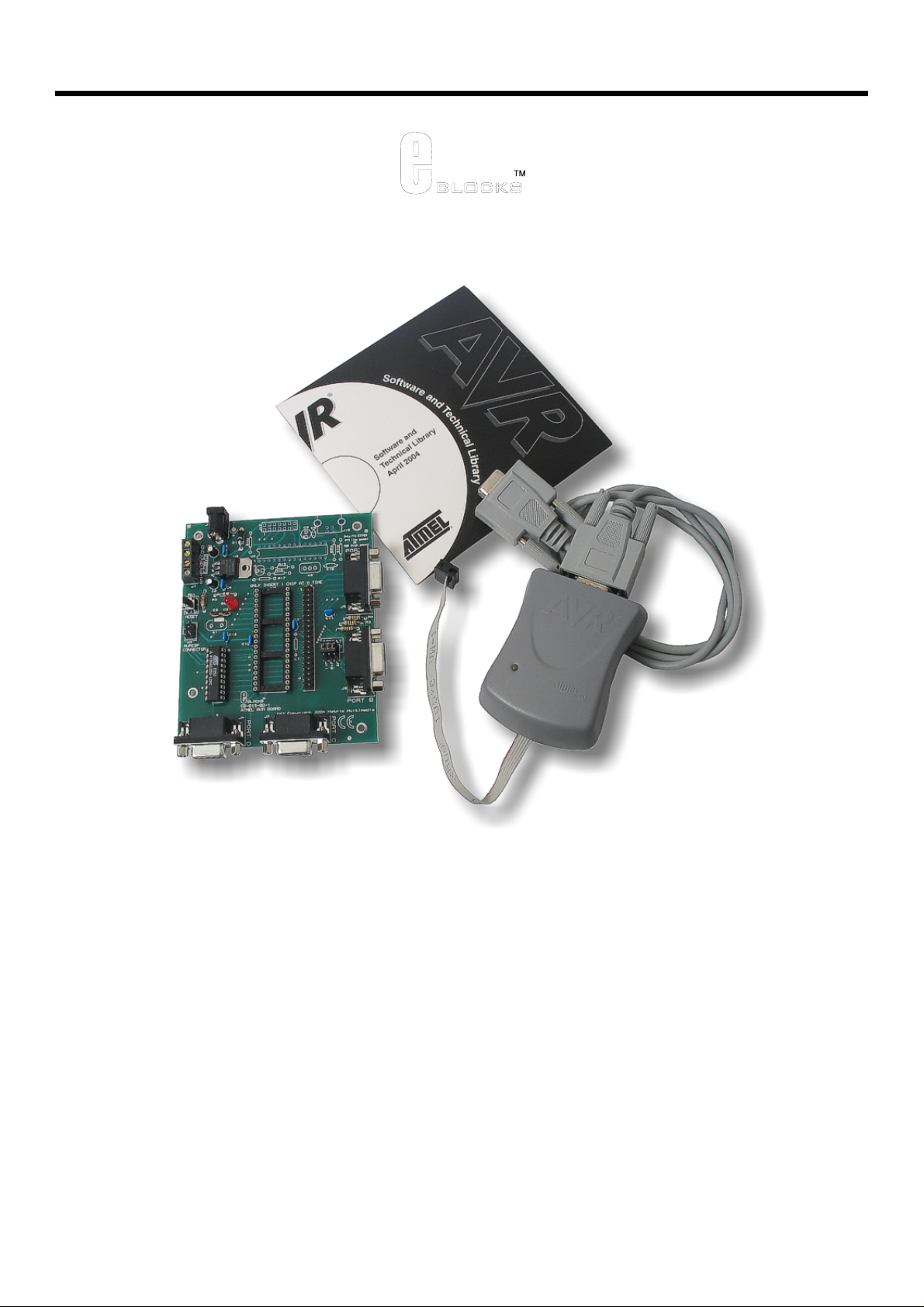
Description
This new AVR® microcontroller programmer connects to your PC via an in circuit programmer to
provide you with one of the world’s lowest cost and most flexible AVR® microcontroller
programmers. The board is fully compatible with our entire range of E-blocks allowing the
investigation into many interesting and exciting projects.
The Atmel AVR® Board allows serial programming of a large selection of 20 and 40 pin Atmel
AVR® devices. This board uses Atmel’s AVR® studio – a free and comprehensive downloadable
AVR® program. The board can be programmed using Assembly and C. It provides ‘clean’ access
to all I/O lines on the relevant Atmel AVR® devices.
Further information on E-blocks is available in a separate document entitled Introduction to Eblocks.doc.
Features
• E-blocks compatible
• Low cost
• Used as a programmer and as a development board
• Programs a wide range of Atmel AVR® devices
• Full suite of programming software
• Xtal operation and internal RC operation
• 4 full I/O ports
Copyright © 2004 Matrix Multimedia Limited Page 3
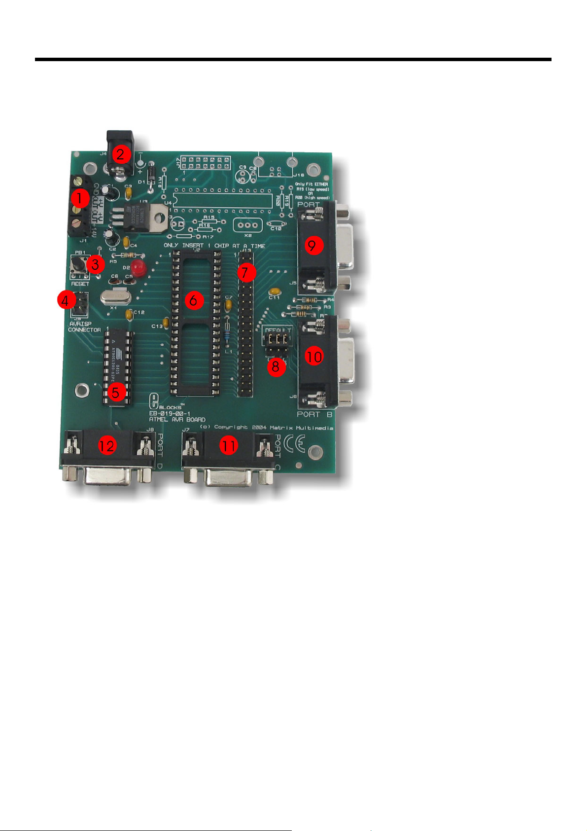
3 Board overview
Matrix Multimedia Atmel AVR® Board
EB19430
1. Screw Terminals
2. Power connector (positive outer – negative inner)
3. Reset switch
4. AVRISP programming connector
5. 20-way AVR® socket with AVR® device
6. 40-way AVR® socket
7. 40-way header mirroring AVR® pins
8. Defualt programming block
9. Port A I/O
10. Port B I/O
11. Port C I/O
12. Port D I/O
Copyright © 2004 Matrix Multimedia Limited Page 4

Matrix Multimedia Atmel AVR® Board
EB19430
4 Getting Started
4.1 Installation instructions - Software
Installing AVR® Studio 4 from AVR® ISP CD
1. Insert Atmel AVR® CD into CD drive.
2. Click ‘Start’ in the pop-up screen. The AVR web page will now be running from the CD.
3. Click ‘Software” on the left hand toolbar.
4. Next, click “AVR Studio 4:” This will show you all the features available using the AVR
Studio software
5. Scroll down to the CD marked “Install AVR Studio4.xx Build (Press “Open” when
prompted). By clicking on this – then pressing “Open” when prompted, will allow you to
install the software
6. Follow the on-screen instructions.
For the most –up-to-date version of this software please visit the Atmel web page at:
www.atmel.com
Installing AVR® Studio 4 from Atmel’s Web page
1. Click on the “Products” icon
2. Using the left hand toolbar, click on “Microcontrollers”, then “AVR 8-bit RISC”
3. Again using the left hand toolbar click on “Tools & Software”
4. Scroll down to the CD marked “AVR Studio4.xx Buildxx. By clicking on this – then
pressing “Open” when prompted, will allow you to install the software.
5. Follow the on-screen instructions.
For more help and guidance on installing AVR® Studio visit the Atmel Website at: www.atmel.com
Copyright © 2004 Matrix Multimedia Limited Page 5

Matrix Multimedia Atmel AVR® Board
EB19430
4.3 Programming the AT90S1200
Testing the Atmel AVR® Board – 90S1200.hex
The following instructions explain the steps to test and use your Atmel AVR® Board. The
instructions assume that AVR® Studio is installed and functional. It also assumes that the test
program 90S1200.hex has been downloaded. This test routine is a step-by-step guide to loading a
programming into the Atmel AVR® Board.
Follow these instructions to test the Atmel AVR® Board
1) Ensure power is supplied to all the Atmel AVR® Board via the power connector J4.
2) Insert EB-004 LED board into Port B of the Atmel AVR® Board
3) Ensure that the Almel AVR® is in correct configuration for programming
- Jumper links for J9, J10 and J11 are in the position marked “DEFAULT”
- Ensure that a 11.052MHz crystal is inserted in the Atmel AVR® Board
4) AVRISP connected to PC and J3 of AVR Board
- Connect RS232 style cable (cable provided) to PC and to AVRISP box (grey
box)
- Connect grey header socket (6-way) to J3 of AVR Board
Ensure the cable is placed with the tab to the outside of the AVR board (this
orientation of the header is shown on the AVR Board silk screen)
For details on AVRISP connector see ‘Programming – Hardware’ in chapter 5
5) Open AVR studio Software
6) Cancel the pop-up window to open any project / files
7) Click on the AVR programming symbol
8) Select AT90S1200 device form “Device” pop-down window
9) Select the “…” button in the Flash section as shown below
10) Navigate to the program 90S1200.hex
11) Press the program button. This will program the AT90S1200 with the test program
90S1200.hex
12) Press the “RESET” button (PB1) on the AVR Board
13) Check the illumination of all LEDs
This should satisfy that the Atmel AVR® Board is fully functional!
Copyright © 2004 Matrix Multimedia Limited Page 6

Matrix Multimedia Atmel AVR® Board
EB19430
Ensuring correct polarity for power supply
Positive Inner/Positive Outer polarity
To set up the correct polarity the connection symbols on the jack need to match those shown
below.
Connector dimensions
The PSU is supplied with a number of connectors.
The correct connector for Matrix Multimedia products
is:
Type D
5.0mm external diameter
2.1mm internal diameter
“D” is marked on one side, down by the pins, and
“5.0x2.1” is marked on the other side.
EB-019-00-1 Atmel AVR®(R) Board requires
Positive Outer power supply
The two arrows – one on the connector socket and one on the connector pin, help you select the
correct side of the power jack, and the symbol shows the correct outer connection.
Copyright © 2004 Matrix Multimedia Limited Page 7

Matrix Multimedia Atmel AVR® Board
5 Block schematic and description
EB19430
14V
J4
0V
+V OUT
+V OUT
14V
PC
Power supply
J2
J1
POWER INDICATOR
Clock circuit
C5 C6
regulation
D2
X1
Vpp
AVRISP
5V
6-way IDC cable
Programming Header
J3
For A VRISP
Recommended
"DEFAULT"
position
J11J10J9
2
B
R
7
RB5RB6
AVR devic es
PB1
Reset
R
[
20 Pin
40 Pin
Port A
[RB0 - RA7]
Port B
P
r
C
o
P
r
D
o
t
D
]
7
D
-
0
R
t
C
R
[
C
-
0
R
[RB0 - RB7]
]
7
1
8
1
8
J13
8
1
8
1
The AVR® Board solution is made up of two parts: A circuit board that allows various slave Atmel
AVR® devices to be programmed, and the program to be executed ‘seamlessly’, and the Windows
based programming utility AVR® Studio.
Copyright © 2004 Matrix Multimedia Limited Page 8

Power Supply
The board can be powered from an unregulated 14V supply. The regulation circuitry will withstand
unregulated 20V as a maximum input voltage and 7V as a minimum. If you are using a DC power
supply then you should use a 14V setting. Power can be connected using the 2.1mm power jack
(positive outer), or the screw terminal connectors J1, J2. The two “+V OUT” screw terminals are
supplied for powering other E-blocks™, supplying approximately +5V. The regulator will supply up
to 400mA via all outputs. LED D3 will indicate that power is connected to the board and that the
voltage regulation circuitry is fully functional.
Please note connector J4 is directly connected to the J1 screw terminal pin 1 labelled ‘+14V’,
therefore any voltage input to J4 will also be available direct from pin 1 of J1. This means that
‘+14V’ will not necessarily be +14V
Note
Remember that other E-blocks will have to receive +5V by placing a connecting wire from the “+V
Out” screw terminal of the Multiprogrammer to the “+V” screw terminal of each E-Block that
requires a voltage.
Programming - Hardware
The AVR® Board connects to a personal computer via the AVRISP or compatible device. The
AVRISP requires +5V and ground connection these are all provided on the board via the
programming header J3.
The following diagram shows the pin-out of the connector J3. The pin-out is the standard pin-out
as used by AVRISP.
Matrix Multimedia Atmel AVR® Board
EB19430
MISO
SCK
/RESET
Figure showing Pin-Out of ISP header J3
By default the pins RB5, RB6, and RB7 are used to program the slave AVR® device. These are
the pins that provide the programming functions MOSI, MISO and SCK respectively. Due to the
nature of programming it is recommended that programming pins have clean signals when
programming, therefore there are 120-Ohm resistors between these pins and the associated Port
B pins. This is achieved by placing the 3-way link block in the “DEFAULT” mode for J9, J10 and
J11. This provides the adequate protection whilst programming.
If problems occur in the programming sequence we recommend completely removing the 3-way
jumper link on J9, J10 and J11. This allows MISO, MOSI and SCK to be completely clean whilst
2
1
34
6
5
VCC
MOSI
GND
Copyright © 2004 Matrix Multimedia Limited Page 9

Matrix Multimedia Atmel AVR® Board
EB19430
programming. This removes the link to Port B, so pins RB5, RB6 and RB7 are only used for
programming.
It is possible to get 100% clean signals on RB5, RB6 and RB7 by placing the 3-way jumper link in
the side opposite to that labelled “default” on J9, J10 and J11. Please note that the AVR® devices
can NOT be programmed when in this state – this state is only recommended if problems with
attachments in Port B occur.
Programming - Software
The CD ROM includes a range of development tools including an Integrated Development
Environment for code writing in assembly and debugging, a professional C compiler, and the ISP
programming software.
DIL Sockets and I / O Ports
The slave AVR® DIL sockets are wired in parallel (see table of connections below) and the ports
are fed out to 4 D-type sockets grouped in ports. These signals are also available on a 40-way
header for expansion purposes. Some of the ports will be inactive. This reflects the pin outs of the
various AVR® devices themselves. For example, the AT90S1200 only has Port B and Port D,
therefore Port A and Port C are inactive. Please refer to device datasheets for availability of port
outputs on each device.
NOTE – Only insert ONE Atmel AVR® device at a time!
Reset Push Button
PB1 provides a reset by pulling the /RESET pin low. PB1 is pulled normally high through a resistor
so that the device will not be reset during normal operation. The programming software has
control over the reset line during programming.
Frequency Selection
By default the board is fitted with a 11.0592 MHz crystal. The crystal fits into a small socket, which
allows the crystal to be easily changed. These frequencies are chosen as they divide down by
AVR® pre-scalers to give suitable frequencies for clock systems and for facilitating serial
communication using standard baud rates.
USB circuitry
In the future there may be a possibility of this device being USB compatible. The PCB has been
manufactured with the circuitry on board to enable quick development.
Note this circuitry is not suppose to be populated
Copyright © 2004 Matrix Multimedia Limited Page 10

Appendix A – Circuit Diagram
Matrix Multimedia Atmel AVR® Board
EB19430
Copyright © 2004 Matrix Multimedia Limited Page 11

Matrix Multimedia Atmel AVR® Board
EB19430
Appendix B – Compatible AVR® devices
This board is designed to be as versatile as possible. This means that it has been designed so
that it maximizes the amount of AVR® devices that can be used with this board.
The following table shows the AVR® devices that are compatible with this board:
20 –Pin AVR®
devices
90S1200 Mega16L
90s2313 Mega16
Tiny2313 Mega32L
Mega32
Mega8535L
Mega8535
LS8535
S8535
Mega163L
Mega163
Mega323L
Mega323
40 –Pin AVR®
devices
The following diagram shows the pin-out of 20 and 40 pin AVR® device that are compatible with
this board.
The items in Red are devices that are compatible but are no
longer manufactured by Atmel®. These devices can be used but
are not recommended.
20 Pin Compatible
AVR® Device Pin Out
40 Pin Compatible
AVR® Device Pin Out
Copyright © 2004 Matrix Multimedia Limited Page 12

Matrix Multimedia Atmel AVR® Board
EB19430
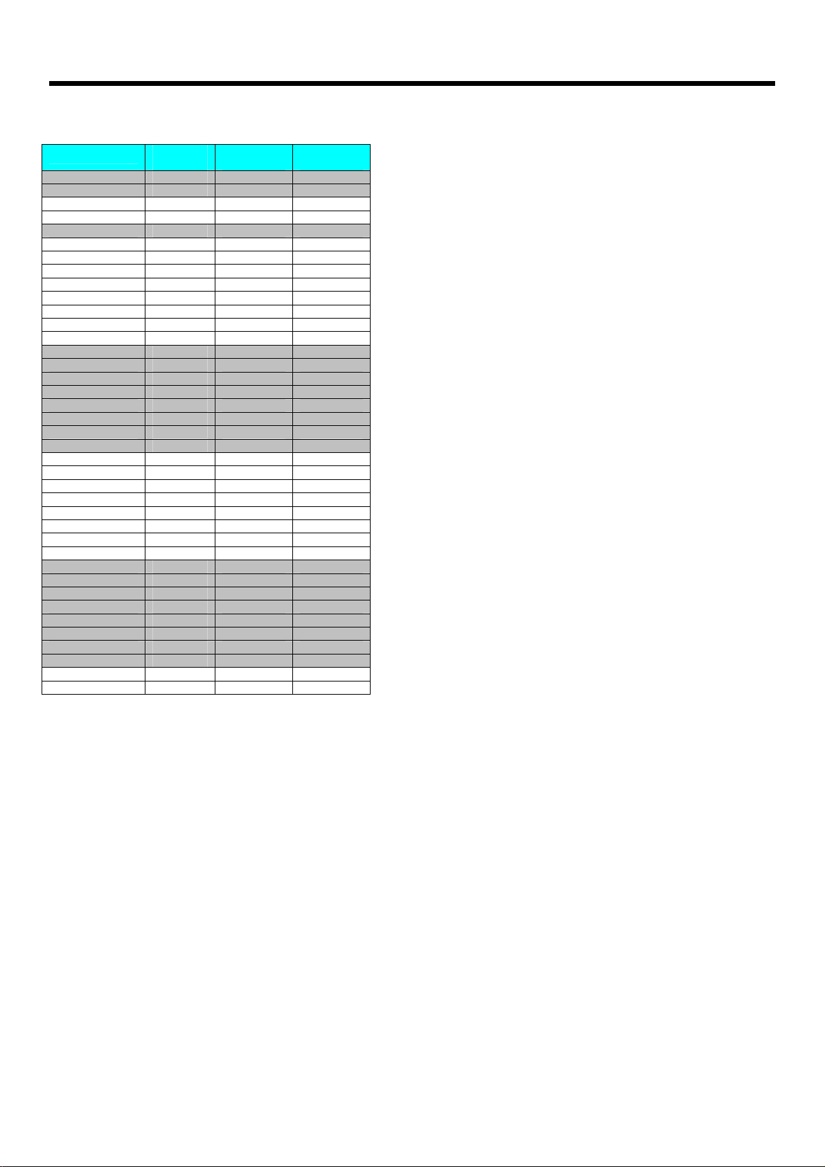
Appendix C - Bus connections
Expansion bus
The pin connections on the expansion bus exactly mirror the pin numbering on the 40-pin DIL socket. Note that the pin numbering on the IDC socket
is slightly different to that on a DIL socket which results in the seemingly odd arrangement of pins on the IDC pin chart.
Pin Comparison Chart
Compatible AVR® Pin out
Bus Name 20 Pin 40 Pin
VDD 20 10
GND 10 11 & 31
XTAL1 5 13
XTAL2 4 12
/RESET 1 9
RA0 40
RA1 39
RA2 38
RA3 37
RA4 36
RA5 35
RA6 34
RA7 33
RB0 12 1
RB1 13 2
RB2 14 3
RB3 15 4
RB4 16 5
RB5 / MOSI 17 6
RB6 / MISO 18 7
RB7 / SCK 19 8
RC0 22
RC1 23
RC2 24
RC3 25
RC4 26
RC5 27
RC6 28
RC7 29
RD0 2 14
RD1 3 15
RD2 6 16
RD3 7 17
RD4 8 18
RD5 9 19
RD6 11 20
RD7 21
AVCC 30
AREF 32
Connections on J3 – Programming header
Bus Name J3
RB5 / MOSI 4
RB6 / MISO 1
RB7 / SCK 3
VDD 2
GND 6
/RESET 5
Copyright © 2004 Matrix Multimedia Limited Page 13
Matrix Multimedia Atmel AVR® Board
Connections on J5 – 40 Pin header connections
Bus Name
VDD 20 10 19
GND 10 11 & 31 20 & 21
XTAL1 5 13 25
XTAL2 4 12 23
/RESET 1 9 17
RA0 40 2
RA1 39 4
RA2 38 6
RA3 37 8
RA4 36 10
RA5 35 12
RA6 34 14
RA7 33 16
RB0 12 1 1
RB1 13 2 3
RB2 14 3 5
RB3 15 4 7
RB4 16 5 9
RB5 / MOSI 17 6 11
RB6 / MISO 18 7 13
RB7 / SCK 19 8 15
RC0 22 38
RC1 23 36
RC2 24 34
RC3 25 32
RC4 26 30
RC5 27 28
RC6 28 26
RC7 29 24
RD0 2 14 27
RD1 3 15 29
RD2 6 16 31
RD3 7 17 33
RD4 8 18 35
RD5 9 19 37
RD6 11 20 39
RD7 21 40
AVCC 30 18
AREF 32 22
20 Pin
Device
40 Pin
device
IDC
connector
EB19430
Copyright © 2004 Matrix Multimedia Limited Page 14
 Loading...