

Page 1

SERVICE MANUAL
Page 2

SECTION A: SETUP AND INSTALLATION INSTRUCTIONS
TIME REQUIRED:
30 Minutes
PURPOSE
To establish a set of instructions for installing and activating Asset Management for Dealers and Users.
DESCRIPTION
The Remote Access Point (RAP) is a wireless access point which received data from transmission radios installed in Matrix 5 and 7 series
products. It is a standalone device (4” x 6” x 2”) that requires an Internet connection via a standard Ethernet cable. The RAP communicates
with BodyLAN™ enabled devices and sends it to the Matrix Asset Management network. The RAP requires only AC power and Internet
access to function. The RAP is embedded with a stripped down version of Windows XP, which runs the Matrix Asset Management application
(AHclient.exe). When powered up, the RAP will boot up to an embedded password protected shell.
To determine how many RAPs a club needs, follow the rules below:
A Each floor with Asset Management enabled equipment should have a RAP.
B Each RAP requires an Ethernet drop (network connection) and 110V power outlet.
C A RAP has a line of site range of 150-400 feet (RAP to equipment). Obstructions will reduce the distance. It is acceptable to have
multiple RAPs in the same room for large workout areas.
D Walls made of metal or concrete greatly reduce the distance that the RAP covers. If equipment is separated by this type of wall, an
additional RAP may be needed for each room depending on the distance the equipment is located from the RAP.
2
Page 3

SECTION A: SETUP AND INSTALLATION INSTRUCTIONS
SETUP - CREATING A NEW USER AND CLUB ID (CAN ONLY BE DONE BY ADMIN)
Once Asset Management has been confirmed to be on the order (on a site survey or PO), and the contact information has been received for a
new facility, a Club ID should be generated in Asset Management. To generate a Club ID:
1 Log into Asset Management at http://asset.johnsonfit.com.
2 Click on the CLUBS tab on the left side of the screen.
3 Click on CREATE NEW CLUB.
4 Determine the group for the club. Click FIND next to the GROUP tab, and select the correct country, region, state, etc. NOTE: If you
type in club information first and then switch the group information, all previously entered information will be lost.
5 Enter the Club Name into the Club Details Box.
6 Add a club location in the Club Locations box. Fill in all of the information available and save.
7 At this point, you will receive the Club ID number for the location. Enter multiple locations for a customer that has a franchise with multiple
locations under the same management to receive multiple Club IDs.
8 Add contact information for Customer Contacts using the Club Contacts Window. If there are multiple locations, indicate which club
each contact correlates to.
9 Click SAVE in the club details before returning to the main screen.
Once the Club ID has been setup for a new facility, a New User should be generated in Asset Management. This will indicate who at the club
will have access to the information generated in Asset Management. To generate a New User:
1 Log into Asset Management at http://asset.johnsonfit.com.
2 Click on the USERS tab on the left side of the screen.
3 Click on CREATE NEW USER.
4 Determine the group for the user. Click FIND next to the GROUP tab, and select the correct country, region, state, etc. NOTE: If you
type in club information first and then switch the group information, all previously entered information will be lost.
5 Once the region is narrowed down, select the Club and then click FIND. A list of all the clubs in that region will show. NOTE: When
determining regions and clubs, the field should be narrowed down as far is required for the user’s visibility. If the user is meant to see an
entire group, country, region, etc, then only narrow the view to that level.
6 Select the club for the user.
7 Fill in the user’s information – name, email, and login.
8 The default login will be (first name).(last name).
9 Set the password as password.
10 Most end user’s role will be BASIC, though it can be changed depending on the user.
11 Create a subscription for the user in the SUBSCRIPTIONS tab. For new users, you will need to click CREATE NEW SUBSCRIPTION,
confirm the club is listed, and then click SAVE.
3
Page 4
SECTION A: SETUP AND INSTALLATION INSTRUCTIONS
INSTALLATION – PARTS AND TOOLS REQUIRED
A Tools Required – Phillips Screwdriver.
B Part Required - RAP Kit – contains the RAP, 1 Antenna, and 1 power cord with AC-DC converter (6’ in length).
1 Power Port (use for cycling power).
2 PS/2 Keyboard (must be plugged in prior to power up if used).
3 USB Connection (will work with most keyboards).
4 Ethernet RJ45 Connection
5 VGA Video Connection for Monitor
6 Switch (non functional).
INSTALLATION - PROCEDURE
Pre-installation Requirements:
1 One active RJ-45 network data jack at the location where the RAP is to be installed.
2 One power outlet – 110VAC duplex outlet at the location where the RAP is to be installed (the RAP consumes less than 2 amps of
current). NOTE: The included power cord is 6’ in length.
3 Network IP assignment: The device is pre-configured with DHCP, allowing for plug and play if used on a DHCP network. NOTE: The
RAP can be installed within your firewall. The RAP communicates bidirectionally on Port 80 just like a web browser. The RAP will only
communicate with the www.actihealth.net web portal.
Installation:
1 Place the RAP in a location within its 150-400 foot range of Matrix Products (best line of sight position).
2 Mount the RAP to a surface using the included adhesive strips or the four mounting screws.
3 Attach the antenna.
4 Connect the Ethernet data cable to the device and wall data jack.
5 Plug the power adaptor into the wall outlet to boot the RAP.
6 The devise is pre-configured with DHCP, allowing for plug and play if used on a DHCP network. 3 beeps signal connection to the web server.
NOTE: If using a Static Network Address, please see the document Accessing and Navigating the RAP.
4
Page 5

SECTION A: SETUP AND INSTALLATION INSTRUCTIONS
SETTING UP MATRIX CARDIO EQUIPMENT FOR ASSET MANAGEMENT (7X AND 7XE CONSOLES):
1 Enter Service Mode (press ENTER, 3, 0, 0, 1, ENTER on the lower keypad).
a. Select Setup (may already be selected).
b. Select Serial Number.
c. Enter the serial number of the console and frame if not already entered (only the last 9 digits of the serial number are entered).
d. Select Date & Time.
e. Enter the date and time if not already entered.
f. Press Home to return to the standard display picture.
2 Enter Engineering Mode (press ENTER, 2, 0, 0, 1, ENTER on the lower keypad).
a. Select Club ID.
b. Enter your Club ID (this should be 6 digits, for example if your Club ID is 110, you will enter 000110).
c. Press Home to return to the standard display picture.
3 Activate the Radio Connection (press ENTER, 2, 0, 0, 4, ENTER on the lower keypad).
4 Reboot the unit.
5 Enter Manager Mode (press ENTER, 1, 0, 0, 1, ENTER on the lower keypad).
a. Select About (may already be selected).
b. Select Software Versions.
c. Check the column on the right side of the screen to make sure that a Radio version is listed. If a Radio version is not listed, check
the connection of the radio at the Upper Control Board. Then repeat steps 3-5.
d. Press Home to return to the standard display picture.
6 Press ENTER, 4, 0, 0, 8, ENTER on the lower keypad. This screen will show you the current information regarding the RAP. Look for a
current date which indicates that the units are communicating with the RAP. Press ENTER, 4, 0, 0, 8, ENTER to return to the standard
display picture.
a. If the date shown is not current, check the connection of the RAP and the radios in the console of the cardio units. Reboot both
RAP and equipment and repeat step 6.
SETTING UP MATRIX CARDIO EQUIPMENT FOR ASSET MANAGEMENT (5X CONSOLE):
1 Enter Engineering Mode (simultaneously press and hold both Level keys for 3-5 seconds or the Incline Up and Speed Down keys on
treadmills).
a. Manager Mode will appear first. Press any Arrow key until Engineering Mode is displayed.
b. Press ENTER.
c. Press any Arrow key until Serial Number is displayed.
d. Press ENTER.
e. Enter the serial number of the console if not already entered (only the last 9 digits of the serial number are entered).
f. Once the serial number of the console is recorded, press ENTER.
g. Press any Arrow key until Club ID is displayed, and then press ENTER.
h. Enter the Club ID.
i. Press ENTER.
j. Press and hold the HOME key until the console returns to the standard display picture.
2 Activate the Radio Connection (press 2, 0, 0, 4, ENTER on the keypad).
3 Reboot the unit.
4 Enter Manager Mode (simultaneously press and hold both Level keys for 3-5 seconds or the Incline Up and Speed Down keys on treadmills).
a. When Manager Mode is displayed, press ENTER.
b. Press any Arrow key until Software is displayed.
c. Press any Arrow key to scroll through the listed software versions. There should now be a version shown for RF Radio. If a Radio
version is not listed, check the connection of the radio at the Upper Control Board. Then repeat steps 2-4.
d. Press Home (or press and release the Emergency Stop on treadmills) to return to the standard display picture.
5
Page 6

SECTION B: NETWORK IMPLEMENTATION WORKSHEET
VIA DIRECT TO MATRIX ASSET MANAGEMENT SERVER DSL/BROADBAND CONNECTION
V2.2
VPN – HOW TO IMPLEMENT VIA DIRECT TO MATRIX ASSET MANAGEMENT DSL/
BROADBAND CONNECTION
VPN connectivity is used to transport data from the Matrix Asset Management server at your facility to the Matrix Asset Management centralized
servers. To get started, you need to provide network wiring from an interface (DSL router/Cable modem, switch or router) on your network to
the Matrix Asset Management server. This must be an unassigned IP address that is accessible on the network.
In order to address your security concerns, no connections are expected from an external origin. It is the Matrix Asset Management server at
your facility that initiates connections. Traffic will flow on port 80:
If you are using firewall/filtering software on your network, traffic on the ports above must be allowed. Further technical detail is available in the
RAP Access Point manual.
6
Page 7

SECTION B: NETWORK IMPLEMENTATION WORKSHEET
SUBMISSION INFORMATION - NETWORK IMPLEMENTATION WORKSHEET EXTERNAL
Once you have completed this page, please email it to Matrix Fitness at service@johnsonfit.com or Fax to 608.839.1280
FACILITY IT CONTACT INFORMATION (MUST BE ON SITE DATE OF INSTALL)
Facility Name:
IT Contact Name:
IT Contact Phone #:
E-mail Address:
3RD PARTY IT CONTACT INFORMATION (IF APPLICABLE)
Company Name:
IT Contact Name:
IT Contact Phone #:
E-mail Address:
PLEASE PROVIDE IP CONFIGURATION FOR THE MATRIX ASSET MANAGEMENT VPN CONNECTION.
Matrix Asset Management will configure its server to these specifications. Please do not use 10.0.0.0 through 10.0.3.255,
as this range is reserved for Matrix Asset Management use.
Subnet Mask (E.g. 255.255.255.0)
Gateway Address (E.g. 192.168.1.1)
Device manufacturer & model number of
your cable modem/DSL router and/or
additional router
Data Rack
Location of Matrix Asset Management Server
Other (specify location):
7
Page 8

SECTION C: REMOTE ACCESS POINT MANUAL
8
INSTRUCTION MANUAL
Page 9

SECTION C: REMOTE ACCESS POINT MANUAL
Table of Contents
About the Remote Access Point (RAP). . . . . . . . . . . . . . . . pg 10
Contents of Box
How Data Moves From the RAP
Physical Components . . . . . . . . . . . . . . . . . . . . . . . . . . . . . . pg 11
Installing the RAP. . . . . . . . . . . . . . . . . . . . . . . . . . . . . . . . . . .pg 12
Pre-Installation Requirements
Installation
Accessing and Navigating the RAP. . . . . . . . . . . . . . . . . . . .pg 12
RAP Configuration Settings and Details . . . . . . . . . . . . . . .pg 15
Upgrading the RAP. . . . . . . . . . . . . . . . . . . . . . . . . . . . . . . . .pg 16
RAP Specifications
Matrix Technical Support
Frequently Asked Questions . . . . . . . . . . . . . . . . . . . . . . . . pg 18
9
Page 10

SECTION C: REMOTE ACCESS POINT MANUAL
ABOUT THE REMOTE ACCESS POINT
The Remote Access Point, or RAP, is a wireless access point for workgroups consisting of more than 100 people. It is a standalone device
(4” x 6” x 2”) that requires an Internet connection via a standard ethernet cable. The RAP communicates with BodyLAN™ - enabled devices and
securely offloads data from these devices and sends it to the Matrix Asset Management network. The RAP requires only AC power and Internet
access to function and has a range of 150-400 feet.
The RAP is embedded with a stripped down version of Windows XP, which runs the Matrix Asset Management application (AHclient.exe).
When powered up, the RAP will boot up to an embedded password-protected shell. Because the RAP runs from Flash memory, the operating
system and applications run off of protected, read-only mapped Flash memory, as such, cannot be corrupted or infected by a virus. A reboot of
the RAP will return it to its original factory state, with the exception of the configuration files that define the network connectivity.
The RAP is only capable of communicating with BodyLAN wireless devices and cannot be used for other wireless network types, such as WiFi.
Once the RAP is properly configured, it will operate the RF transceiver, collect data from sensors and transmit the data to the ActiHealth
servers at:
http://client.actihealth.net
http://fusion.actihealth.net
CONTENTS OF BOX
1 Remote Access Point (RAP)
1 Antenna
1 power cord with AC-DC converter (six feet in length)
1 Cat 5e network cable
Heavy duty adhesive strips for mounting (attached to the RAP)
4 mounting screws (for alternate mounting)
HOW DATA MOVES FROM THE RAP
The Remote Access Point actively listens for proprietary BodyLAN
RF data beacons. If there is a BodyLAN device beaconing, the RAP
will detect it. The RAP will wirelessly communicate with the device
and collect the data, repackage it, and transmit it via an HTTP POST
transaction to the Matrix Asset Management servers. The data is
then stored in the unique BodyLAN device storage location. All
communication between the RAP and the Matrix Asset Management
servers takes place over TCP port 80, and all transactions are initiated
as outbound HTTP requests from the RAP. There are no Matrix Asset
Management server-initiated transactions to the RAP.
10
Page 11

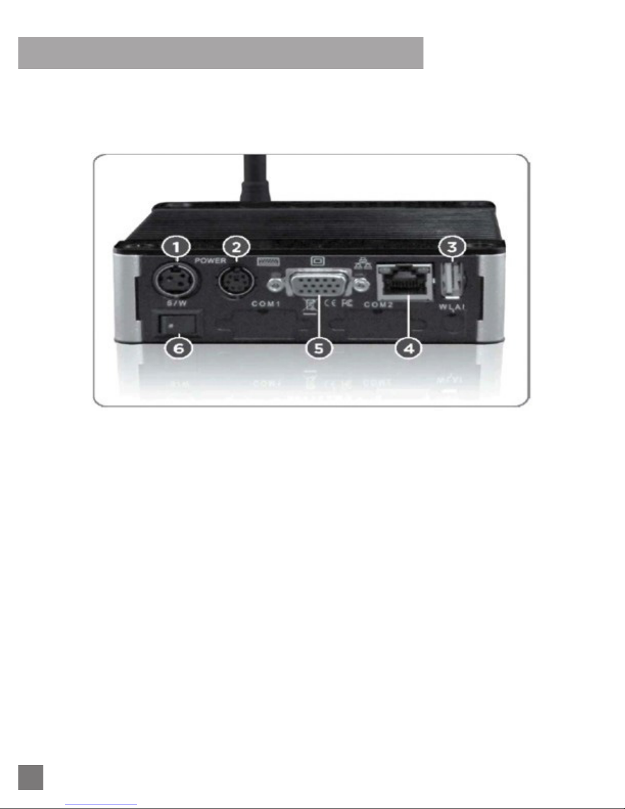
PHYSICAL COMPONENTS
SECTION C: REMOTE ACCESS POINT MANUAL
1 Power Port (use for cycling power)
2 PS/2 Keyboard (must be plugged in prior to power up if used)
3 USB Connection (will work with most keyboards)
4 Ethernet RJ-45 Connection
5 VGA Video Connection for Monitor
6 Switch (non-functional)
11
Page 12

SECTION C: REMOTE ACCESS POINT MANUAL
INSTALLING THE RAP
Listed below are the steps that must be completed before installing the RAP, as well as RAP installation guidance.
Please read all information carefully.
PRE-INSTALLATION REQUIREMENTS
1 One (1) network data jack equipped with an RJ-45 connector at the location where the RAP is to be installed.
2 One (1) power outlet - 110vAC duplex outlet at the location where the RAP is to be installed (the RAP consumes less than 2 amps of
current). Note: the included power cord is six feet in length.
3 Network IP assignments: The device is pre-configured with DHCP, allowing for plug-and-play if used on a DHCP network. If using a static
network address, please see ACCESSING AND NAVIGATING THE RAP for static network instructions.
Note: The RAP can be installed within your firewall - the RAP communicates bidirectionally on Port 80 just like a web browser. The RAP will
only communicate with the www.actihealth.net web portal.
INSTALLATION
1 Place the RAP in a location within its 150-400 foot range of Matrix Products.
2 Mount the RAP to a surface using the included adhesive strips or the four mounting screws.
3 Attach the antenna.
4 Connect the ethernet data cable to the device and to the wall data jack.
5 If using a PS/2 keyboard and monitor for configuring the RAP, please connect them now. Otherwise, skip to step 6.
6 Plug the power adaptor into the wall outlet to boot the RAP..
7 The device is pre-configured with DHCP, allowing for plug-and-play if used on DHCP network.
ACCESSING AND NAVIGATING THE RAP
Ths section will cover accessing the RAP, help topics, syntax for modifying the RAP configuration and information for rebooting the RAP.
The following addresses will need to be assigned in the RAP configuration:
IP Address (XX:XX:XX:XX)
IP Gateway (XX:XX:XX:XX)
IP Mask Bits (255:255:255:XXX)
IP DNS (XX:XX:XX:XX)
IP Metric 1
The RAP shell uses a DOS command line. If you know the IP address of the RAP, you may Telnet into the RAP directly from a networked
computer (see figure 1). Otherwise, the following components may be needed to set the parameters above:
Keyboard with PS/2 or USB connector
Monitor
12
Figure 1: Logging into your RAP using Telnet from a
DOS prompt.
Note: The IP address shown is an example, use the IP
address of your RAP.
Page 13

SECTION C: REMOTE ACCESS POINT MANUAL
Once you connect to the RAP you will be presented with a login screen. The default login credentials are:
login: administrator
password: wireless
Note: nothing will appear on the screen when typing the password - this is normal behavior.
Figure 2: The RAP login screen.
After successfully logging in as the administrator you will be presented with a confirmation message and the RAP prompt (RAP>) will be
displayed (see figure 3). Type help at the RAP prompt for a list of the available commands (see figure 4).
Figure 3: The RAP prompt will appear after a
successful login.
Figure 4: Typing help displays the RAP help menu.
Typing any of the commands listed in the help menu will reveal further information, allow you to configure the RAP, or send commands directly
to the RAP. You may also type help followed by any of the commands for additional assistance (see figure 5).
Figure 5: An example of typing help version.
13
Page 14

SECTION C: REMOTE ACCESS POINT MANUAL
The following screens will guide you through important menu information and options.
Figure 6: The Versions screen.
Note: These are the minimum acceptable revisions at
the time of this document creation.
To configure the RAP you will need to use the config menu. Figure 7 shows the help config screen, which shows the syntax for viewing and
modifying the device configuration.
Figure 7: The help config screen shows syntax and
examples.
Note: When finished, the RAP must be rebooted for
configuration changes to take effect.
To display the current value for a setting you would type config get followed by the category and setting. For example, to view the current
platform for the RAP, type: config get app platform
To change the value for a setting you would type config set followed by the category, setting and its new value. For example, to change the
platform setting to “fusion”. type: config set app platform fusion
The following section will review the RAP configuration settings and their details.
14
Page 15

SECTION C: REMOTE ACCESS POINT MANUAL
RAP CONFIGURATION SETTINGS AND DETAILS
Type config get all to view the configuration settings and current values (see figure 8)
Figure 8: The config all command will display all
configurable RAP settings and their current values.
Note: each of the three column titles is important
when modifying the RAP settings.
To change a setting, type config set followed by the category, setting and the new value. For example, to change the RAP from using
DHCP to static IP address, you would type config set app ipaddress followed by the new IP address (see figure 9)
The following are the configuration settings for the RAP that will allow it to be used with any of the listed platforms and applications. The
settings may be changed through the local console with a keyboard and mouse, or from a remote Telnet session. Settings are not case
sensitive. For help and syntax when changing RAP settings, type help config at the RAP prompt (see page 12)
APP / Platform
APP / BCNAStartup Should be set to
APP / AMClientStartup Should be set to true when the RAP is used with ActiHealth devices.
APP / IpAddress Sets the IP address of the RAP on the network. May be set to address (ex: 10.0.0.48)
APP / IpMask
Specifies the platform that the RAP is to communicate with. The setting should be fusion. If you believe you are
using an older version of the ActiHealth web site, please contact Customer Service at 866.693.4863
Sets the IpMask when using a static IP address (ex: 255.255.252.0). Should be set to null when DHCP is
configured for the IP address
15
Page 16

SECTION C: REMOTE ACCESS POINT MANUAL
Figure 9: The left example shows you how to change
the IP address of the RAP to 192.168.1.186
Note: 192.168.1.186 is being used as an example.
Once done configuring the RAP, please remember to reboot the device by typing reboot as the RAP prompt.
APP / IpGateway
APP / IpMetric Should be set to true when the RAP is used with ActiHealth devices.
APP / IpDNS
APP / AHServerURL
APP / AHOptions
Sets the IP address of the gateway for the RAP to use if one is available on the network. Must be set to the
correct gateway unless DHCP is configured for the IP address, in which case it should be set to null.
Used to set the IP address of the DNS server for the RAP if a DNS server is available on the network. Set to
null if configured with DHCP. The RAP must have at least one DNS Server.
Sets the URL of the server that the RAP is to send ActiHealth data to. Set to null for the RAP to send
ActiHealth data to a default URL based on the platform setting.
Set to null for no options. When the platform is set to Fusion, AHOptions may be set to /sound. The sound
option causes the RAP to provide audible notification of its status. When the RAP is connected to the network
it will emit a single low pitch tone if it is unable to communicate with the FitLinxx servers, and a double highpitched tone when it is able to communicate again. It will also emit a very short low-volume chirp whenever it
successfully transfers data from a device to the FitLinxx servers.
UPGRADING THE RAP
Matrix Asset Management will provide you with a USB memory stick upgrade (part #990043) if an upgrade is required. For more information
please contact our Customer Care Department at 866.693.4863
16
Page 17

SECTION C: REMOTE ACCESS POINT MANUAL
RAP SPECIFICATIONS
The RAP is set up to be an Internet appliance for the movement of data from the Matrix Asset Management proprietary BodyLAN RF network to
the Internet via a standard RJ-45 ethernet connection. This is the sole purpose of this appliance. The RAP is running the embedded Windows
XP Operating System and will boot-up the password-protected shell that has been installed. The embedded Windows platform is stripped
down, only providing the services needed to operate the Matrix Asset Management application (AHclient.exe).
SPECIFICATIONS:
Dimensions 4” x 2” x 6”
Power 2 Amps at 110 volts
BodyLAN RF Protocol Radio Frequency ISM spectrum (2.429 GHz)
Max RF Power Level 1mwatts/cm2
Channel Spacing 1Mhz
Frequency deviation +/- 156 Hz
GFSK modulation Yes
db Receive sensitivity (-93)
Data Rate Up to 1 Mbps (250 Kbps typical)
Range Up to 100 meters
Low sensitivity to interference Yes
Operating System Embedded Windows XP
Internet Connection IEEE 802.3 RJ-45 100 mb ethernet
Power and Ethernet connectivity indicators Yes
Power Switch Yes (disabled)
MTBF 100,000 hrs
Temperature Range 0-125 degrees F
MATRIX ASSET MANAGEMENT TECHNICAL SUPPORT SERVICES
If you have further questions, please email: service@johnsonfit.com or contact Customer Service at 1-866-693-4863
17
Page 18

SECTION C: REMOTE ACCESS POINT MANUAL
FREQUENTLY ASKED QUESTIONS
Q. Will the RAP work on a DHCP network?
A. Yes, by default it is configured for DHCP. However, the RAP needs to be able to send and receive HTTP traffic via
Port 80 to client.actihealth.net and fusion.actihealth.net. Proxies are allowed, but the RAP requires communication
both ways, and the above sites need to be “white listed”.
Q. Can the RAP be assigned a static IP so that I can bring it onto my network?
A. Yes. Please refer to RAP Configuration Settings and Details on page 15 of this document for information on
the parameters that need to be set if you do not use DHCP.
Q. What is the range of the RAP?
A. The RAP has an approximate range of 150-400 feet, depending on its line of sight. Position the antenna so that it
has a good view of the area to maximize its overall range.
Q. What do I need in order to install the RAP?
A. You need to have a data connection with Internet access. If using DHCP you can simply plug the RAP into your
network. The RAP works approximately 90% of the time out of the box with no configuration modifications. If you
have your network on a higher security level, you will have to “white list” client.actihealth.net and fusion.actihealth.net.
Please call FitLinxx Customer Care if you need more information.
Q. What wireless protocol does the RAP use to upload activity data, is it WiFi?
A. Although the RAP looks like a WiFi device, it uses a proprietary wireless protocol developed by Matrix Asset
Management called BodyLAN. It operates in the 2.4 GHZ ISM band and co-exists with WiFi, Bluetooth and digital
phones without interfering. The protocol is CE and FCC compliant, and holds FDA approvals as well.
Q. Can I set the RAP up wirelessly.
A. No. However, if you know the IP address of the RAP you can access it remotely and make changes. This
procedure is outlined in this document and can also be found in our upgrade instructions.
Q. What is the best location for the RAP?
A. Place the RAP in slow traffic areas such as the main lobby or office point of entry, time card punch clocks, break
rooms, cafeterias or wherever people spend time.
Q. At what point should I consider a RAP over the USB-connected access points?
A. The RAP should always be considered over the USB options when being used in a public place. Using a USB
connected access point where there are other applications running on the PC will limit the volume of devices it can
offload at any given time. Additionally, if it is on a PC that could go into sleep, hibernate or a security mode, the USB
access point may stop offloading.
As an appliance the RAP is typically less expensive than a USB access point when considered with the cost of a
dedicated PC. If you have a dedicated PC, it can be used with a USB access point instead of a RAP. However, you
should configure its settings so that it never sleeps, hibernates or shuts off the AHclient.exe application. Failure to do
this may result in data not being transferred to the web.
18
Page 19

SECTION C: REMOTE ACCESS POINT MANUAL
Q. How does the RAP send Activity data to the web site?
A. It uses the ActiHealth client (AHclient.exe), which uses HTTP post/response, connecting to port 80 to post/
receive information through the Internet at ActiHealth servers:
http://client.actihealth.net
http://fusion.actihealth.net
Q. How do I access the RAP?
A. You can plug in a USB or PS/2 keyboard and a monitor to directly access the RAP. If the RAP is currently running
when you attach the peripherals, please reboot by cycling its power. Once rebooted, you will have direct access to
the RAP.
You can also Telnet into the RAP, if you know the IP address of the device on your network. See the instructions in
this document beginning on page 5, Accessing and Navigating the RAP.
19
Page 20

Asset Management Service Manual 1.0 | © 2011 Matrix Fitness
Matrix Fitness
1600 Landmark Drive,
Cottage Grove, WI 53527
 Loading...