

Page 1

A7X-01 ASCENT TRAINER
SERVICE MANUAL
Page 2

Page 3

CHAPTER 1: SERIAL NUMBER LOCATION ........................................................... 1
CHAPTER 2: IMPORTANT SAFETY INSTRUCTIONS
2.1 Moving the Unit ........................................................................................................... 3
2.2 Read and Save These Instructions ............................................................................. 4
2.3 Electrical Requirements ............................................................................................. 5
CHAPTER 3: PREVENTATIVE MAINTENANCE
3.1 Recommended Cleaning Tips .................................................................................... 6
3.2 Check for Damaged Parts ......................................................................................... 6
3.3 Care and Maintenance Instructions ........................................................................... 7
3.4 Preventative Maintenance Checklist .......................................................................... 7
CHAPTER 4: CONSOLE OVERLAY AND WORKOUT DESCRIPTION
4.1 Console Description ................................................................................................... 8
4.2 Workout Setup Steps - Manual ................................................................................... 9
4.3 Workout Setup Steps - Fat Burn ................................................................................. 9
4.4 Workout Setup Steps - Training Workout.................................................................... 9
4.5 Workout Setup Steps - Cooper Fitness Test ............................................................... 10
4.6 Workout Setup Steps - Target Heart Rate .................................................................. 11
4.7 Workout Setup Steps - Constant Watts ...................................................................... 11
4.8 Auto Calibration Procedure ......................................................................................... 12
CHAPTER 5: MANAGER MODE
5.1 Manager Mode Overview ............................................................................................ 13
5.2 Manager Mode - About Tab......................................................................................... 14
5.3 Manager Mode - Time Tab .......................................................................................... 15
5.4 Manager Mode - Defaults Tab..................................................................................... 16
5.5 Manager Mode - Language Tab .................................................................................. 17
5.6 Manager Mode - TV Tab ............................................................................................. 18
CHAPTER 6: ENGINEERING MODE
6.1 Engineering Mode Overview ....................................................................................... 19
6.2 Engineering Mode - Calibration Tab............................................................................ 20
6.3 Engineering Mode - Errors Tab ................................................................................... 21
6.4 Engineering Mode - Statistics Tab .............................................................................. 22
6.5 Engineering Mode - Self Power Tab ........................................................................... 23
6.6 Engineering Mode - Clubs Tab.................................................................................... 24
6.7 Engineering Mode - Club ID Tab ................................................................................. 25
CHAPTER 7: SERVICE MODE
7.1 Service Mode Overview .............................................................................................. 26
7.2 Service Mode - Setup Tab........................................................................................... 27
7.3 Service Mode - Test Tab ............................................................................................. 28
7.4 Service Mode - Date / Time Tab ................................................................................. 29
7.5 Service Mode - Log Tab .............................................................................................. 30
TABLE OF CONTENTS
Page 4

iv
TABLE OF CONTENTS
CHAPTER 8: TROUBLESHOOTING
8.1 Electrical Diagram ...................................................................................................... 31
8.2 LCB Error Indicators .................................................................................................. 32
8.3 Console Error Codes .................................................................................................. 33
8.4 Troubleshooting Various Issues .................................................................................. 34
8.5 Troubleshooting - Entertainment Keypad Issues ........................................................ 35
8.5 TV Troubleshooting .................................................................................................... 36
CHAPTER 9: PART REPLACEMENT GUIDE
9.1 Front Disk Replacement ............................................................................................ 37
9.2 Front Shroud Removal ................................................................................................ 40
9.3 Lower Control Board (LCB) Replacement .................................................................. 41
9.4 ECB (Electromagnetic Brake) Replacement ............................................................... 42
9.5 ECB Belt Replacement ............................................................................................... 44
9.6 Drive Belt Replacement .............................................................................................. 45
9.7 Pulley Axle Set Replacement ...................................................................................... 46
9.8 Drive Axle Set Replacement ....................................................................................... 47
9.9 Console Replacement ................................................................................................. 48
9.10 Overlay & Keypad Replacement ................................................................................. 49
9.11 Handlebar Assembly Replacement ............................................................................. 52
9.12 Rear Shroud Replacement ......................................................................................... 53
9.13 Incline Motor Replacement ......................................................................................... 54
9.14 Dual Action Handlebar Replacement .......................................................................... 56
9.15 Foot Pedals Replacement ........................................................................................... 57
9.16 Pedal Arm Replacement ............................................................................................. 58
9.17 Link Arm Replacement ................................................................................................ 59
9.18 Swing Arm Replacement ............................................................................................. 61
9.19 Rear Pivot Arm Replacement ...................................................................................... 63
9.20 Testing the Ascent Trainer ........................................................................................... 64
CHAPTER 10: EXPLODED DIAGRAMS
10.1 Ascent Trainer Specifications ..................................................................................... 65
10.2 Fasteners & Assembly Tools ....................................................................................... 66
10.3 Ascent Trainer Assembly Steps ................................................................................. 67
10.4 Stabilizing the Ascent Trainer ...................................................................................... 71
10.5 TV Programming Instructions ..................................................................................... 72
CHAPTER 11: UPGRADES
11.1 Belt Tensioner Bearing Replacement .......................................................................... 74
11.2 Bearing Assembly Shimming .............................................................................. ...... 75
11.3 Upgrading Hand grips with Resistance Buttons ..................................................... . . 76
11.4 Installing Adjustable Tensioner .................................................................................... 77
CHAPTER 12: SOFTWARE UPGRADE PROCEDURE
12.1 Software Upgrade Procedure ..................................................................................... 81
Page 5
1
SERIAL NUMBER PLACEMENT
CHAPTER 1: SERIAL NUMBER LOCATION
1.1 SERIAL NUMBER LOCATION
Page 6
2
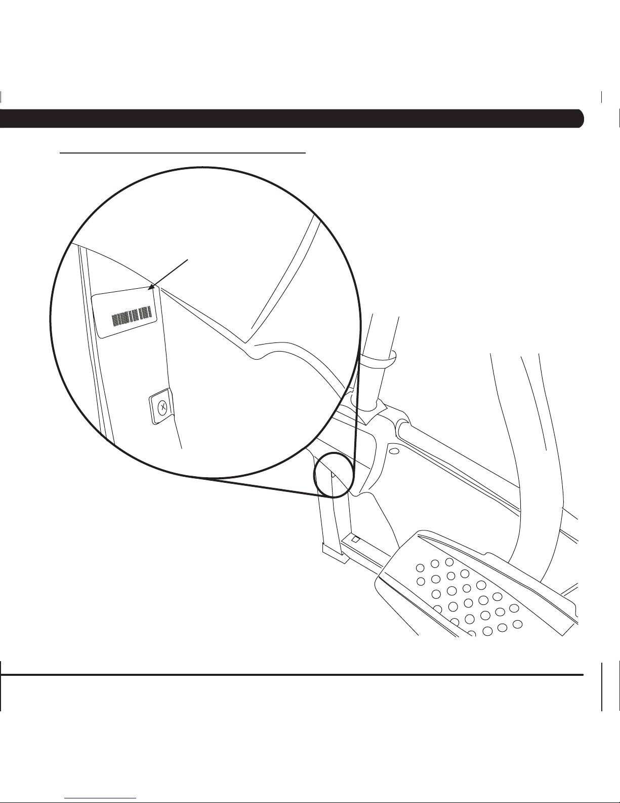
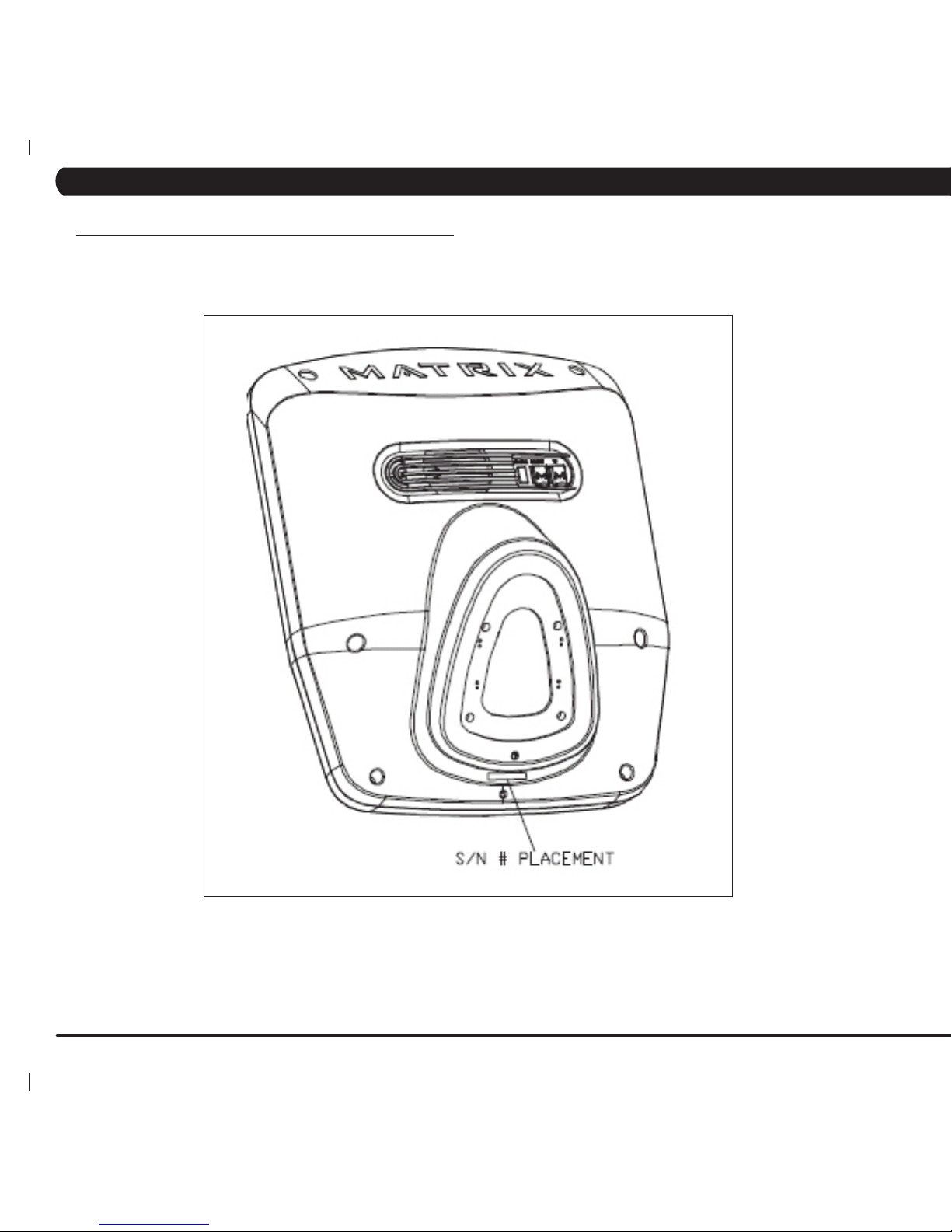
1.1 SERIAL NUMBER LOCATION - CONTINUED
universal console serial number location
CHAPTER 1: SERIAL NUMBER LOCATION
Page 7
3
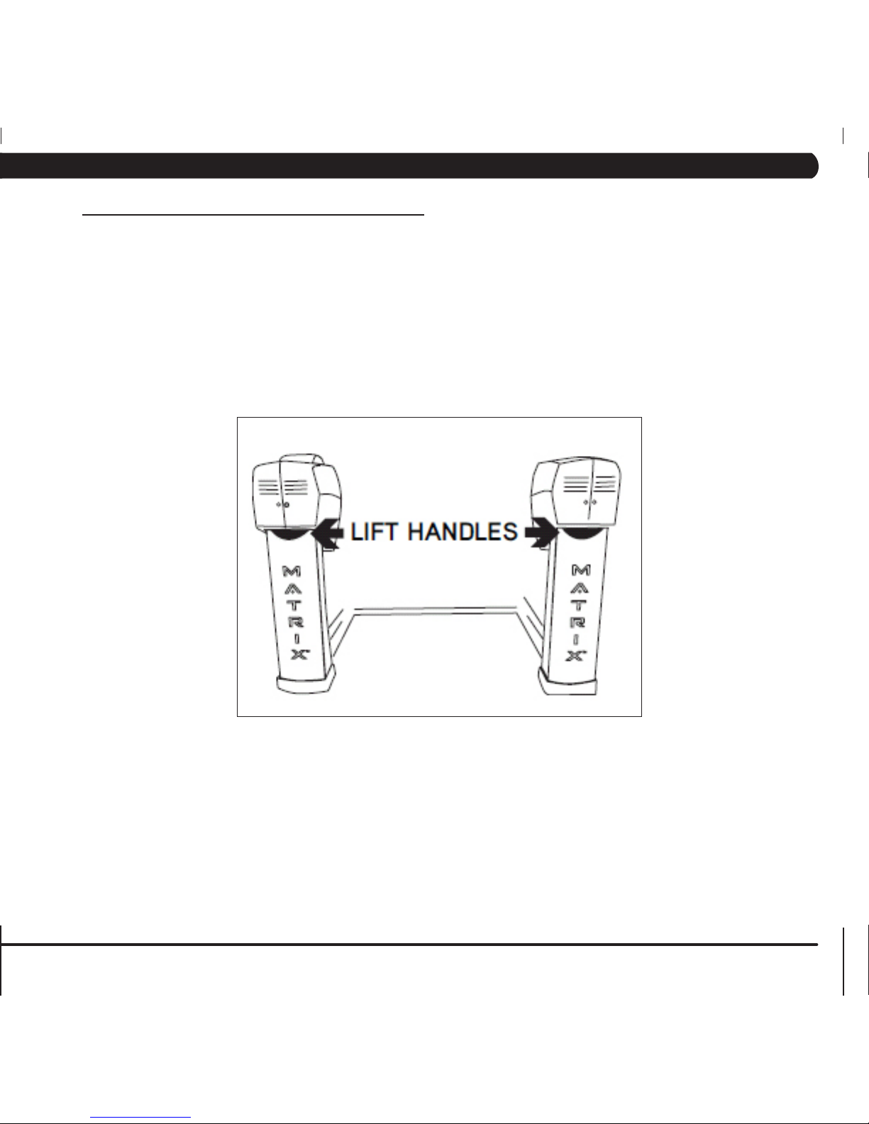
Two hand holds are located just above the MATRIX logo on the rear
legs.
The A7x-01 Ascent Trainer weighs 395 lbs. To avoid injury to the
user and the unit, be sure to have proper assistance to move the
unit.
2.1 MOVING THE UNIT
CHAPTER 2: IMPORTANT SAFETY INSTRUCTIONS
Page 8

4
This Ascent Trainer is intended for commercial use. To ensure
your safety and protect the equipment, read all instructions before
operating the MATRIX Ascent Trainer.
When using an electrical product, basic precautions should always be
followed including the following:
• Anapplianceshouldneverbeleftunattendedwhenplugged
in. Unplugtheunitfromtheoutletwhennotinuseandbefore
puttingonortakingoffanyparts.
• Thisproductmustbeusedforitsintendedpurpose
describedinthisservicemanual. Donotuseother
attachmentsthatarenotrecommendbythemanufacturer.
Attachmentsmaycauseinjury.
• Topreventelectricalshock,neverdroporinsertanyobject
intoanyopening.
• Donotremovetheconsolecovers.Serviceshouldonlybe
donebyanauthorizedservicetechnician.
• NeveroperatetheAscentTrainerwiththeairopening
blocked.Keeptheairopeningclean,freeoflintandhair.
• Donotcarrythisunitbyit’ssupplycordorusethecordas
ahandle.
• ClosesupervisionisnecessarywhentheAscent Traineris
usedbyornearchildrenordisablepersons.
• Donotuseoutdoors.
• Donotoperatewhereaerosol(spray)productsarebeing
usedorwhenoxygenisbeingadministered.
• Todisconnect,turnallcontrolstotheoffposition,then
removetheplugfromtheoutlet.
• ConnectthisAscentTrainertoaproperlygroundedoutlet
only.
• Donotusetheequipmentinanywayotherthandesignedor
intendedbythemanufacturer.ItisimperativethatallMatrix
FitnessSystemsequipmentisusedproperlytoavoidinjury.
• Keephandsandfeetclearofmovingpartsatalltimesto
avoidinjury.
• Unsupervisedchildrenmustbekeptawayfromthisequip-
ment.
• Donotwearlooseclothingwhileontheequipment.
CAUTION! Ifyouexperiencechestpains,nausea,dizziness,or
shortnessofbreath,stopexercisingimmediatelyandconsult
yourphysicianbeforecontinuing.
CAUTION! Anychangesormodificationstothisequipment
couldvoidtheproductwarranty.
2.2 READ AND SAVE THESE INSTRUCTIONS
CHAPTER 2: IMPORTANT SAFETY INSTRUCTIONS
Page 9
5
MATRIX DEDICATED CIRCUIT/ELECTRICAL REQUIREMENT INFO
All Matrix Ascent Trainers require the use of a 15 amp or 20 amp
“dedicated circuit,” with a non-looped (isolated) neutral/ground, for the
power requirement. Quite simply this means that each outlet you plug
Ascent Trainers into should not have anything else running on that
same circuit besides other Ascent or Incline Trainers (up to 3 per 15
amp circuit and 4 per 20 amp circuit). The easiest way to verify this is to
locate the main circuit breaker box, and turn off the breaker(s) one at a
time. Once a breaker has been turned off, the only thing that should not
have power to it are the Ascent/Incline Trainers in question. No lamps,
vending machines, fans, sound systems, or any other item should lose
power when you perform this test.
Non-looped (isolated) neutral/grounding means that each circuit must
have an individual neutral/ground connection coming from it, and
terminating at an approved earth ground. You cannot “jumper” a single
neutral/ground from one circuit to the next.
In addition to the dedicated circuit requirement, the proper gauge wire
must be used from the circuit breaker box, to each outlet that will have
the maximum number of units running off of it. If the distance from
the circuit breaker box, to each outlet, is 100 ft or less, then 12 gauge
wire may be used. For any distance greater than 100 ft from the circuit
breaker box to the outlet, 10 gauge wire must be used.
For your safety and Ascent Trainer performance, the ground on this
circuit must be non-looped. Please refer to NEC article 210-21 and 210-
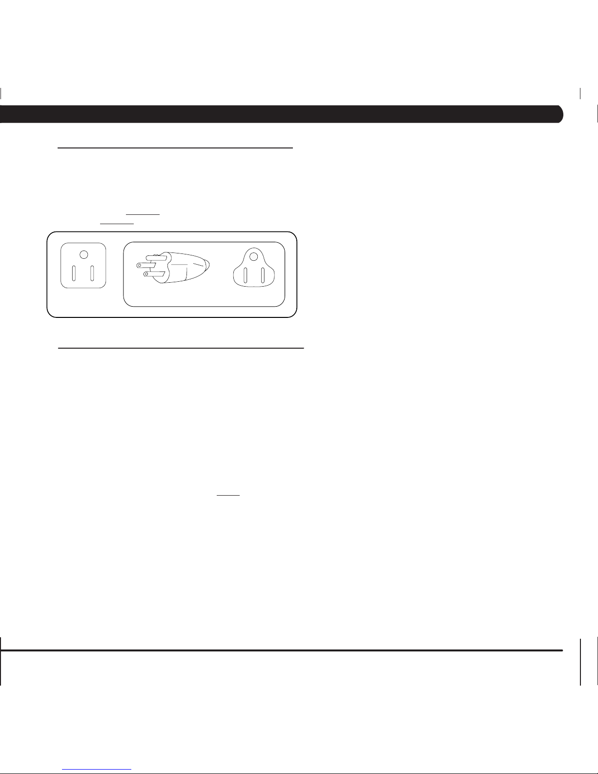
23. Your Ascent Trainer is provided with a power cord with a plug listed
below and requires the listed outlet. Any alterations of this power cord
could void all warranties for this product. Multiple Ascent Trainers can
be powered on one dedicated circuit. (3 units per 15 Amp and 4 units
per 20 Amp dedicated circuit.)
GROUNDING INSTRUCTIONS:
The Matrix Ascent Trainer must be grounded. If it should
malfunction or break down, grounding provides a path of least
resistance for electric current to reduce the risk of electric shock.
The Ascent Trainer is equipped with a cord having an equipment
grounding conductor and a grounding plug. The plug must be
plugged into an appropriate outlet that is properly installed and
grounded in accordance with all local codes and ordinances. If the
user does not follow these grounding instructions, the user could
void the Matrix limited warranty.
DANGER: Improper connection of the equipment grounding
conductor can result in the risk of electric shock. Check with a
qualified electrician if the user is in doubt as to whether the product
is properly grounded. Do not modify the plug provided with the
product if it will not fit the outlet, have a proper outlet installed by an
electrician
2.3 ELECTRICAL REQUIREMENTS
CHAPTER 2: IMPORTANT SAFETY INSTRUCTIONS
Page 10

6
3.1 RECOMMENDED CLEANING TIPS
Preventative maintenance and daily cleaning will prolong the life and
look of your MATRIX Ascent Trainer.
Please read and follow these tips.
• Positiontheequipmentawayfromdirectsunlight.TheintenseUV
light can cause discoloration on plastics.
• Locateyourequipmentinanareawithcooltemperaturesandlow
humidity.
• Cleanwithasoft100%cottoncloth.
• Cleanwithsoapandwaterorothernon-ammoniabasedallpur-
pose cleaners.
• Wipefootpads,handles,heartrategrips,andhandlebarsclean
after each use.
• Donotpourliquidsdirectlyontoyourequipment.Thiscancause
damage to the equipment and in some cases electrocution.
• Checkpedalmotionandstability.
• Adjustlevelingfeetwhenequipmentwobblesorrocks.
• Maintainacleanareaaroundequipment,freefromdustanddirt.
DO NOT use any equipment that is damaged or has worn or broken
parts. Use only replacement parts supplied by Matrix Fitness
Systems.
MAINTAIN LABELS AND NAMEPLATES. Do not remove labels
for any reason. They contain important information. If unreadable or
missing, contact Matrix Fitness Systems for a replacement. 1-866693-4863, www.matrixfitness.com
MAINTAIN ALL EQUIPMENT Preventative maintenance is the key
to smooth operating equipment. Equipment needs to be inspected
at regular intervals. Defective components must be replaced
immediately. Improperly working equipment must be kept out of use
until it is repaired. Ensure that any person(s) making adjustments
or performing maintenance or repair of any kind is qualified to do
so. Matrix Fitness Systems will provide service and maintenance
training at our corporate facility upon request or in the field if proper
arrangements are made.
3.2 CHECK FOR DAMAGED PARTS
CHAPTER 3: PREVENTATIVE MAINTENANCE
Page 11
7
3.3 CARE AND MAINTENANCE INSTRUCTION
Inspect power cords
Check E-stop cord/button
Vacuum/clean under cover
Check motor drive belt
Check running belt
Flip/replace deck
De-wax rollers
Notes/comments
Check resistance system
Lubricate pivot points
Check connecting joints
Remove covers, check
belts
Check pedal & crank
Check/lube seat
adjustment
Verify electronics operation
Clean/lube guide rods
Inspect belt/cable assy.
Check locking pins
Check pulleys
Inspect upholstery
Check/tighten hardware
Lubricate Acme screw
MAKE: MODEL: S/N
LOCATION: TECHNICIAN: DATE:
Inspect power cords
Check E-stop cord/button
Vacuum/clean under cover
Check motor drive belt
Check running belt
Flip/replace deck
De-wax rollers
Notes/comments
Check resistance system
Lubricate pivot points
Check connecting joints
Remove covers, check
belts
Check pedal & crank
Check/lube seat
adjustment
Verify electronics operation
Clean/lube guide rods
Inspect belt/cable assy.
Check locking pins
Check pulleys
Inspect upholstery
Check/tighten hardware
Lubricate Acme screw
In order to maximize life span, and minimize down time, all MATRIX equipment
requires regular cleaning, and maintenance items performed on a scheduled
basis. This section contains detailed instructions on how to perform these
items, the frequency of which they should be done, and a check list to sign
off each time service is completed for a specific machine. Some basic tools
and supplies will be necessary to perform these tasks which include (but may
not be limited to):
* Metric Allen wrenches
* #2 Phillips head screwdriver
* Adjustable wrench
* Torque wrench (capability to read foot lbs, and inch lbs)
* Lint free cleaning cloths
* Teflon based spray lubricant
* Mild, water soluble, detergent – such as “Simple Green”, or other Matrix
approved product
* Teflon based spray lubricant such as “Super Lube”, or other Matrix approved
product
* Vacuum cleaner with an extendable hose and crevasse tool attachment
Please find the worksheet sample for our equipment provided in this
manual and make copies as needed. Keep them up to date as the required
service / maintenance items are performed. It is critical that you also log the
accumulated (total) amount of miles or running hours on the equipment each
time service or maintenance is performed.
You may periodically see addendums to this document, as the Matrix Technical
Support Team identifies items that require specific attention, the latest version
will always be available on the Matrix web site, www.matrixfitness.com
DAILY MAINTENANCE ITEMS
1) Clean the entire machine using water and mild detergent such as
“Simple Green”, or other Matrix approved solutions (cleaning agents
should be alcohol and ammonia free).
QUARTERLY MAINTENANCE ITEMS
1) Check all connecting joint areas for tightness of bolt assemblies.
2) Ensure that there is little, or no free play at all joint assemblies once bolts
have been tightened. Installation of washer kits may be required if free
play does not come out from tightening bolts.
3) Remove plastic covers, and lubricate the ball joint where the Link Arm
and Handlebar join together. A grease gun, with a needle fitting adapter
is required for this (Matrix recommends using Superlube brand grease
with PTFE {Teflon} additive).
4) Remove plastic covers, and lubricate the Acme screw on the left and
right incline motors (Matrix recommends using Superlube brand grease
with PTFE {Teflon} additive).
MAKE: MODEL: S/N
LOCATION: TECHNICIAN: DATE:
3.4 PREVENTATIVE MAINTENANCE CHECKLIST
CHAPTER 3: PREVENTATIVE MAINTENANCE
Page 12
8
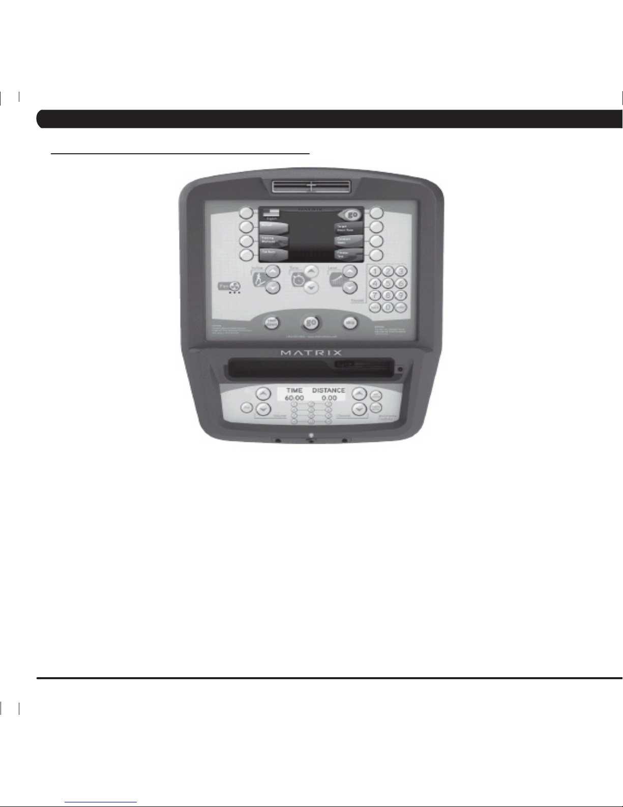
MULTI-PURPOSEKEYS: Keys have different functions depending on
each screen.
Go: One touch Start.
enter: To confirm each program setting.
uP / DoWn incline: Easy information and incline selection.
uP / DoWn level: Easy information and level selection.
uP / DoWn time: Easy information and time adjustment.
stoP: Ends workout and shows workout summary data.
NUMBERKEYPAD: Workout data input for workout setup. Level
adjustment during workout.
cool DoWn: Puts the Ascent Trainer into Cool Down Mode.
Fan: Allows for fan speed selection (fan has 3 operating speeds).
4.1 CONSOLE DESCRIPTION
A7X ENTERTAINMENT ZONE
iPoD®: Will take the user directly to the iPod screen to allow for iPod
control and play list selection.
volume uP / DoWn: Adjusts the volume output through the
headphone jack of either integrated console TV or iPod output.
NUMBERKEYPAD: Allows for easy TV channel selections.
cHannel uP / DoWn: Allows for channel selection.
DISPLAYMODE: Allows user to cycle through console display options,
iPod, TV, or profile display.
last cHannel: Allows the user to cycle between the current
channel and the previous channel they were viewing.
CHAPTER 4: CONSOLE OVERLAY AND WORKOUT DESCRIPTION
Page 13

9
Go - Press to immediately begin a workout. Workout, resistance
level, and time will automatically go to default settings. Pressing
GO will not prompt user for age, weight, or level settings.
1) Start pedaling and press the GO key to begin your workout. 2)
The display will read 3, 2, 1, Begin and then the program will start.
manual - Manual allows the user to input more information
while defining their own workout. Calorie expenditure will be more
accurate when inputting information in Manual than by pressing GO.
1) Start pedaling and press the key next to MANUAL on the
display.
2) Select the key next to Level and follow the prompts to set.
3) Select the key next to Time and follow the prompts to set. .
4) Select the key next to Weight and follow the prompts to set.
5) Select the key next to GO and the display will read 3, 2, 1, and
then the program will begin.
rollinG Hills - The Rolling Hills program is a level based program
that automatically adjusts the resistance level to simulate real terrain.
1) Start pedaling and press the key next to TRAINING WORKOUTS on
the display, and then press the key next to ROLLING HILLS.
2) Select the key next to Level and follow the prompts to set.
3) Select the key next to Time and follow the prompts to set. .
4) Select the key next to Weight and follow the prompts to set.
5) Select the key next to GO and the display will read 3, 2, 1, and then
the program will begin.
intervals - The Intervals program is a level based program that
automatically adjusts the resistance of the machine from low to high
intensity settings at regular intervals.
1) Start pedaling and press the key next to TRAINING WORKOUTS on
the display, and then press the key next to INTERVAL TRAINING.
2) Select the key next to Level and follow the prompts to set.
3) Select the key next to Time and follow the prompts to set. .
4) Select the key next to Weight and follow the prompts to set.
5) Select the key next to GO and the display will read 3, 2, 1, and then
the program will begin.
GLUTETRAININGWORKOUT - This program was designed
to increase your range of motion and target the thighs and glutes. By
varying a high incline throughout the workout you can engage significant
glute recruitment and enjoy a great workout. You will be asked to enter
in a minimum resistance level and a maximum resistance level. The
maximum resistance is applied at your peaks and the minimum resistance
is applied in the valleys. Choose levels that are appropriate for you. A
great recommended starting point is a Minimum Resistance Level of 1
and a Maximum Resistance Level of 8. After you are comfortable with this
setting, try higher levels for both. Incline levels cannot be adjusted during
this workout as it is an incline based workout.
1) Start pedaling and press the key next to TRAINING WORKOUTS on
the display, and then press the key next to GLUTE TRAINING.
2) Select the key next to Time and follow the prompts to set. .
3) Select the key next to Weight and follow the prompts to set.
4) Select the key next to Maximum Resistance and follow the prompts to
set.
5) Select the key next to Minimum Resistance and follow the prompts to
set.
6) Select the key next to GO and the display will read 3, 2, 1, and then
the program will begin.
4.2 WORKOUT SETUP STEPS - MANUAL 4.4 WORKOUT SETUP STEPS - TRAINING WORKOUTS
4.3 WORKOUT SETUP STEPS - FAT BURN
Fat burn - Fat burn is a level based program that is designed
to help users burn fat through various resistance level changes.
1) Start pedaling and press the FAT BURN key.
2) Select the key next to Level and follow the prompts to set.
3) Select the key next to Time and follow the prompts to set. .
4) Select the key next to Weight and follow the prompts to set.
5) Select the key next to GO and the display will read 3, 2, 1, and
then the program will begin.
CHAPTER 4: CONSOLE OVERLAY AND WORKOUT DESCRIPTION
Page 14

10
Fitness test -The Cooper Fitness Test measures cardiovascular fitness and proves an estimated sub-maximal VO2 result. It is based
on power output according to ACSM standards and was developed by the Cooper Institute© (www.cooperinstitute.org). User RPMs must
remain between 60-80 RPM during the test. The test will end when the user can no longer maintain this speed. Use of a heart rate strap is
optional but provides more data.
The test starts at a low intensity level and gradually increases in intensity (difficulty) every 2 minutes. As it increases, the user must maintain
60-80 RPM to advance to the next level. The test could take upwards of 30+ minutes for very fit individuals. Once the test ends a recovery
period (cool down) will begin and the user's results are calculated and displayed. Results are based on the number of stages completed.
Incline will not be adjustable during the test.
1) Start pedaling and press the key next to FITNESS TEST on the display.
2) Select the key next to Age and follow the prompts to set.
3) Select the key next to Gender and follow the prompts to set. .
4) Select the key next to Weight and follow the prompts to set.
5) Select the key next to GO and the display will read 3, 2, 1, and then the program will begin.
6) Once the workout is complete, the display will read the results of the Fitness Test.
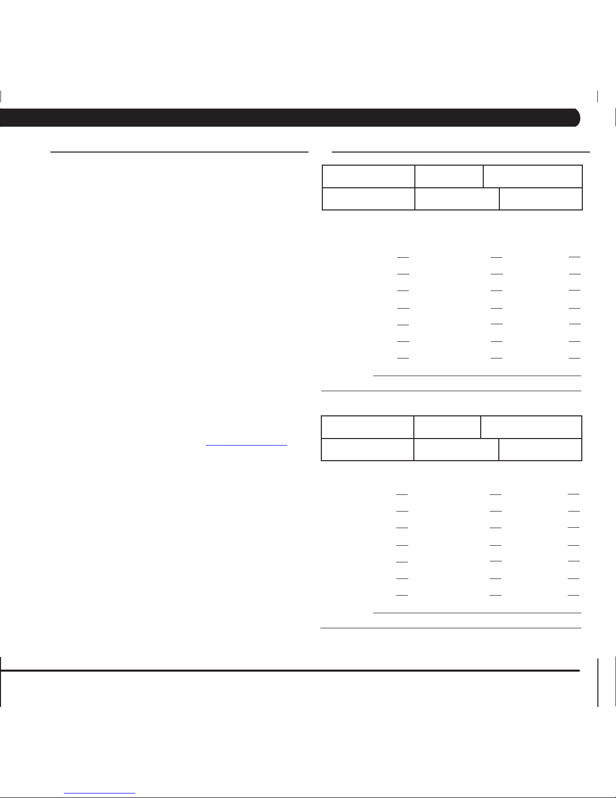
STAGE COMPLETE:
1 Well Below Average
2 Well Below Average
3 Below Average
4 Below Average
5 Average
6 Average
7 Above Average
8 Above Average
9+ Well Above Average
4.5 WORKOUT SETUP STEPS - COOPER FITNESS TEST
CHAPTER 4: CONSOLE OVERLAY AND WORKOUT DESCRIPTION
Page 15
11
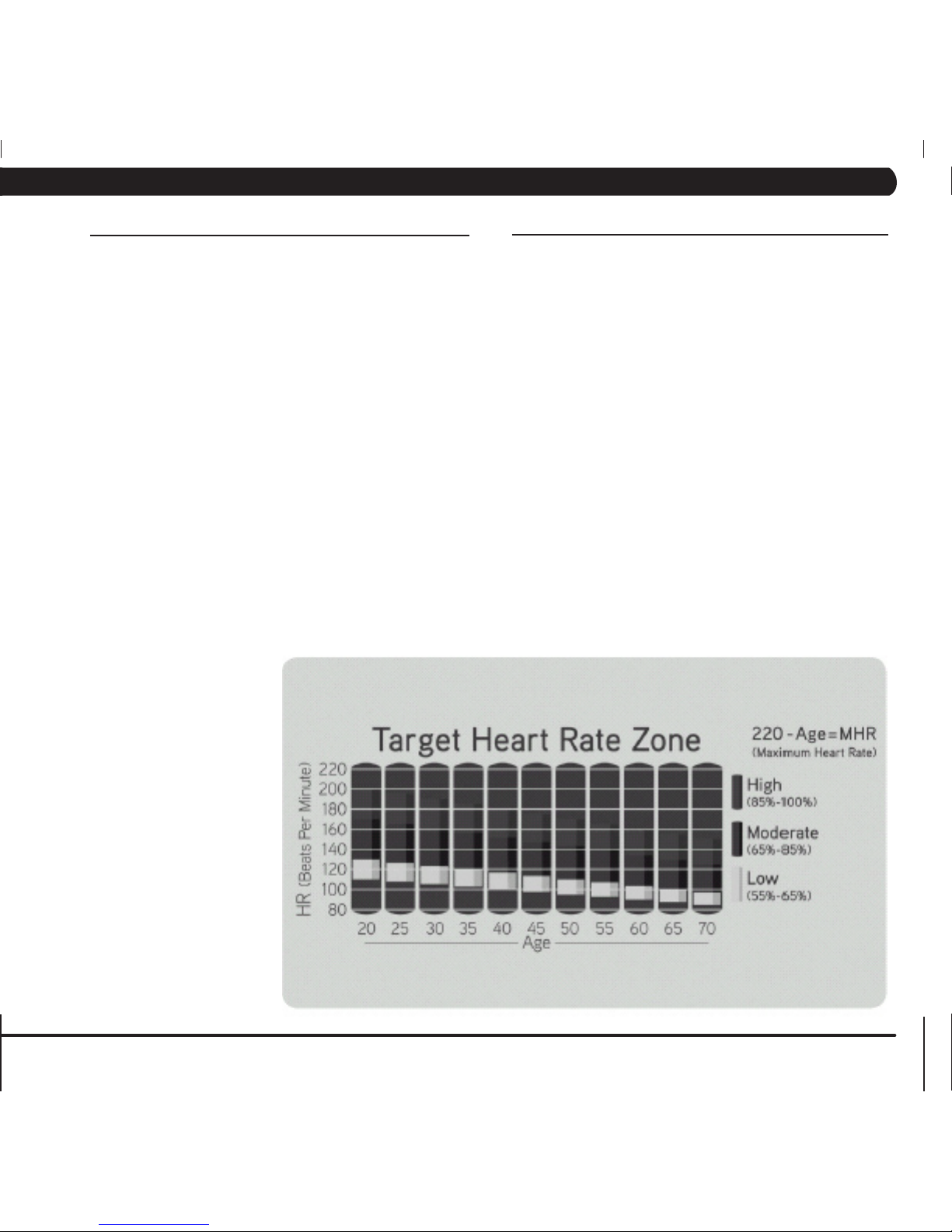
tarGet Heart rate - The Matrix Ascent Trainer comes
with standard digital contact heart rate sensors and are POLAR
telemetry compatible. The heart rate control workout mode allows
the user to program their desired heart rate zone, and the Ascent
Trainer will automatically adjust the level based upon the user's
heart rate. The heart rate zone is calculated using the following
equation:(220-Age)8%=targetheartratezone.Theusermustwear
a POLAR telemetric strap or continually hold onto the contact heart
rate grips for this workout.
Locate the metal sensors on the handlebars of the Ascent Trainer.
Notice that there are two separate pieces of metal on each grip.
You must be making contact with both pieces of each grip to get
an accurate heart rate reading. You can grab these sensors in any
program to view your current heart rate.
1) Start pedaling and press the key next to TARGET HEART RATE.
2) Select the key next to Age and follow the prompts to set.
2) Select the key next to Percent of HR and follow the prompts to
set.
3) Select the key next to Time and follow the prompts to set. .
4) Select the key next to Weight and follow the prompts to set.
5) Select the key next to GO and the display will read 3, 2, 1, and
then the program will begin.
constant Watts - Constant Watts is a unique program
that allows you to vary your cadence or RPM and the Ascent
Trainer's resistance level will adjust accordingly to your selected
goal. The quicker you pedal, the less resistance for the goal
selected.
1) Start pedaling and press the CONSTANT WATTS key.
2) Select the key next to Watts and follow the prompts to set.
3) Select the key next to Time and follow the prompts to set. .
4) Select the key next to Weight and follow the prompts to set.
5) Select the key next to GO and the display will read 3, 2, 1, and
then the program will begin.
4.6 WORKOUT SETUP STEPS - TARGET HEART RATE 4.7 WORKOUT SETUP STEPS - CONSTANT WATTS
CHAPTER 4: CONSOLE OVERLAY AND WORKOUT DESCRIPTION
Page 16

12
4.8 AUTO CALIBRATION PROCEDURE
AUTO CALIBRATION PROCEDURE
After initial installation or after installing a new lift motor, Auto Calibration must be run. This will synchronize the 2
lift motors to ensure the unit elevates evenly.
1) Press ENTER 3, 0, 0, 1, ENTER and the unit will go into Service Mode.
2) Press the button next to TEST on the display.
3) Press the button next to AUTO CALIBRATION on the display.
4) This will run the Auto Calibration. If the calibration passes, it will say Complete. Press and hold the STOP key to return to normal function.
5) If the auto calibration fails, contact the Matrix Technical Support Team.
CHAPTER 4: CONSOLE OVERLAY AND WORKOUT DESCRIPTION
Page 17
13
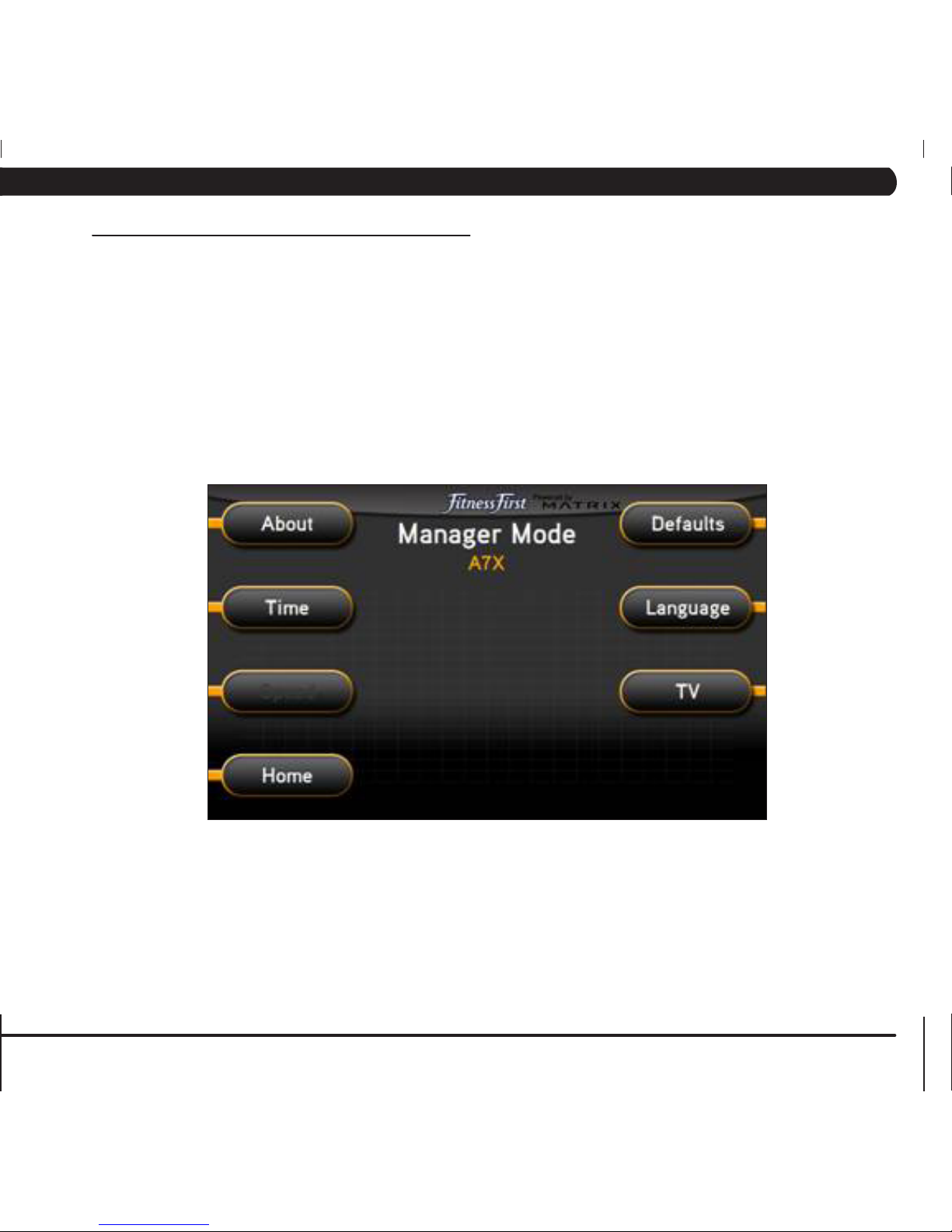
The Manager's Custom Mode allows the club owner to customize the Ascent Trainer for the club.
1) To enter Manager Mode, press ENTER, 1, 0, 0, 1, ENTER on the upper display. Manager Mode will appear on the display (Figure A).
2) Select the key next to the setting that needs to be changed, and follow the prompts to change.
3) Press the ENTER key once the desired setting is correct to save.
4) Press HOME or press and hold the STOP key for 3-5 seconds to return to normal operation.
5.1 MANAGER MODE OVERVIEW
FIGURE A
CHAPTER 5: MANAGER MODE
Page 18
14
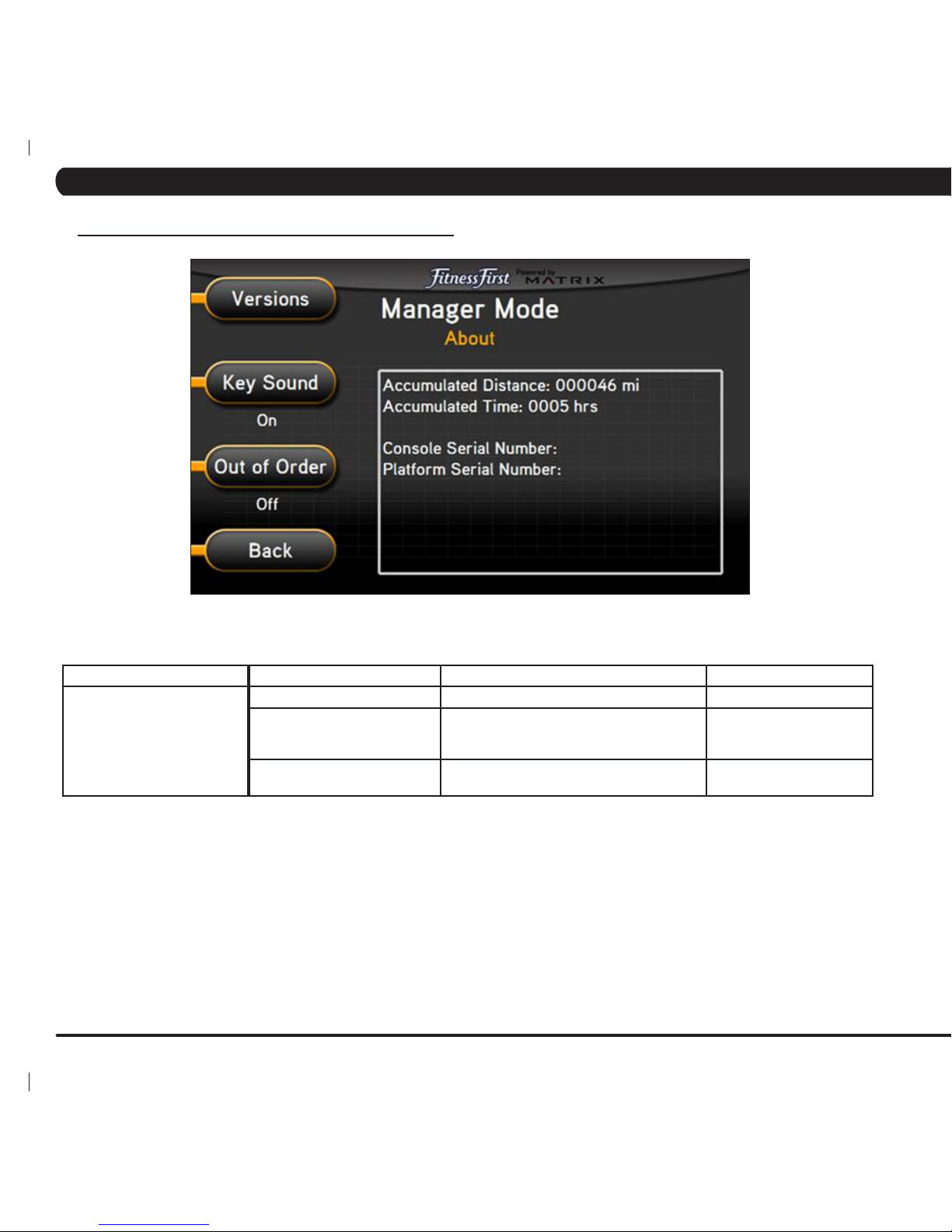
5.2 MANAGER MODE - ABOUT TAB
FUNCTION & DEFAULTS DESCRIPTIONS MODIFIED
Versions Software version. Cannot be modified.
Key Sound
Default: On
Controls whether there is a key sound when
a key is pressed and whether it is a beep or
through the speakers.
On / Off
Out of Order
Default: Off
This option allows the club to put the console
into an "out of order" status.
On / Off
MANAGER MODE
About
CHAPTER 5: MANAGER MODE
Page 19
15
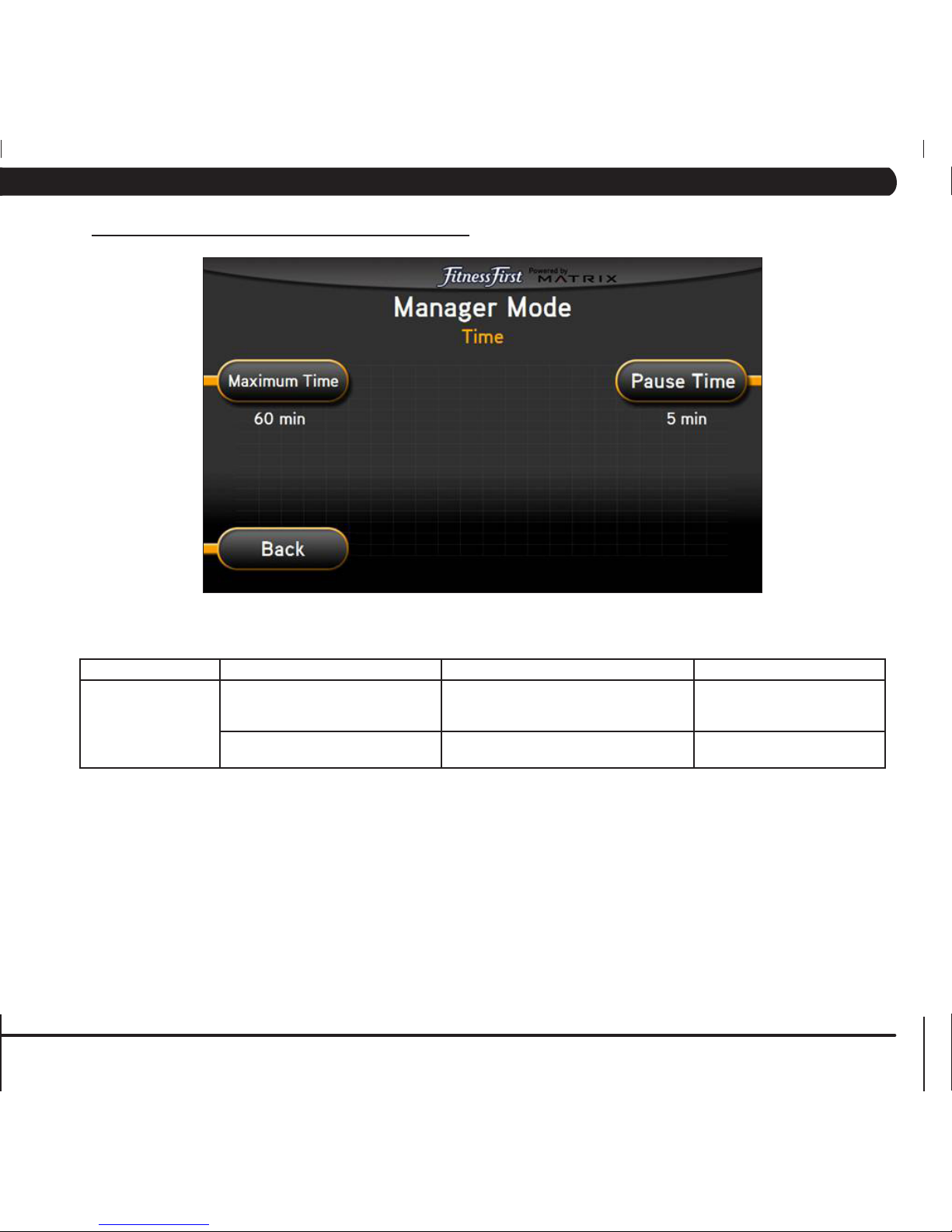
5.3 MANAGER MODE - TIME TAB
FUNCTION & DEFAULTS DESCRIPTIONS MODIFIED
Maximum Time
Default: 60 Minutes
This option allows the club to set the
maximum workout duration limits during
peak and non peak hours.
Maximum: 99 Minutes
Minimum: 5 Minutes
Pause Time
Default: 5 Minutes
This option controls the default pause time. Maximum: 10 Minutes
Minimum: 1 Minute
MANAGER MODE
Time
CHAPTER 5: MANAGER MODE
Page 20
16
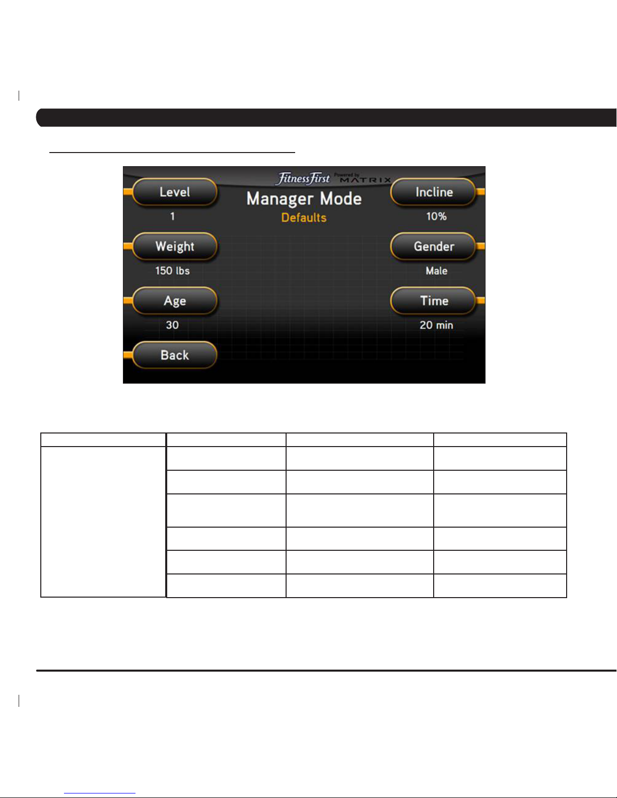
5.4 MANAGER MODE - DEFAULTS TAB
FUNCTION & DEFAULTS DESCRIPTION MODIFIED
Level
Default: 1
This option controls the dafault
program level.
Maximum: 1
Minimum: 20
Age
Default: 30
This option controls the default user's
age used in the target HR calculations.
Maximum: 100
Minimum: 10
Weight
Default: 150 lbs / 68 kg
This option controls the default weight
used in the calorie calculations.
Displayed in pounds or kilograms.
Maximum: 400 lbs / 180 kg
Minimum: 80 lbs / 36 kg
Incline
Default:0%
Starting incline level at each program
start.
Range0-100%
Gender
Default: Male
Setting the user as Male or Female. Male or Female
Time This option controls the default
program time.
Maximum: Max Time Setting
Minimum: 5 Minutes.
MANAGER MODE
Defaults
CHAPTER 5: MANAGER MODE
Page 21
17
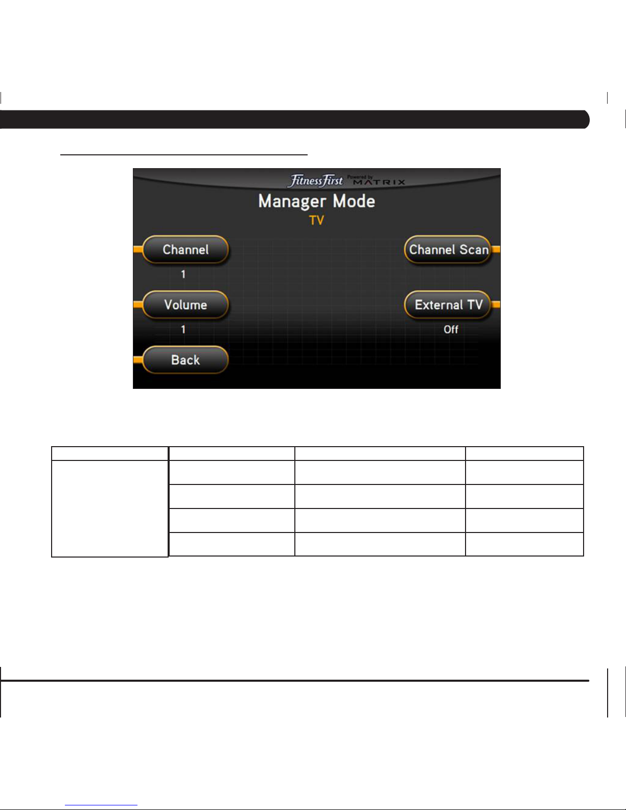
5.5 MANAGER MODE - TV TAB
FUNCTION & DEFAULTS DESCRIPTIONS MODIFIED
Channel
Default: 1
This option controls the default TV channel
on start up.
Channels 1-999
Volume
Default: 1
This option controls the default TV volume
on start up.
Maximum: 17
Minimum: 1
Channel Scan This option scans the local TV system for
channels.
N/A
External TV
Default: Off
This option controls the external TV power. On / Off
MANAGER MODE
TV
CHAPTER 5: MANAGER MODE
Page 22

18
5.6 MANAGER MODE - LANGUAGE TAB
MANAGER MODE FUNCTION & DEFAULTS DESCRIPTIONS MODIFIED
Language Select default language. This option allows the user to select a flag for a
specific language.
N/A
FLAG UNIT
Mile
Mile
KM
KM
KM
LANGUAGE
English
German
FLAG UNIT
KM
KM
KM
KM
KM
LANGUAGE
Spanish
Dutch
Italian
Japanese
FLAG UNIT
KM
KM
KM
KM
KM
LANGUAGE
Chinese
Portuguese
French
CHAPTER 5: MANAGER MODE
Page 23
19
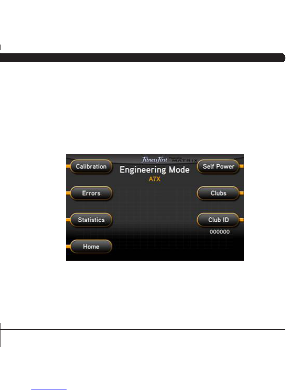
6.1 ENGINEERING MODE OVERVIEW
The Engineering Mode allows the club owner to keep track of the technical settings and error history for the Ascent Trainer.
1) To enter Engineering Mode, press ENTER, 2, 0, 0, 1, ENTER on the upper display. Engineering Mode will appear on the display (Figure A).
2) Select the key next to the setting that needs to be changed, and follow the prompts to change.
3) Press the ENTER key once the desired setting is correct to save.
4) Press HOME or press and hold the STOP key for 3-5 seconds to return to normal operation.
FIGURE A
CHAPTER 6: ENGINEERING MODE
Page 24
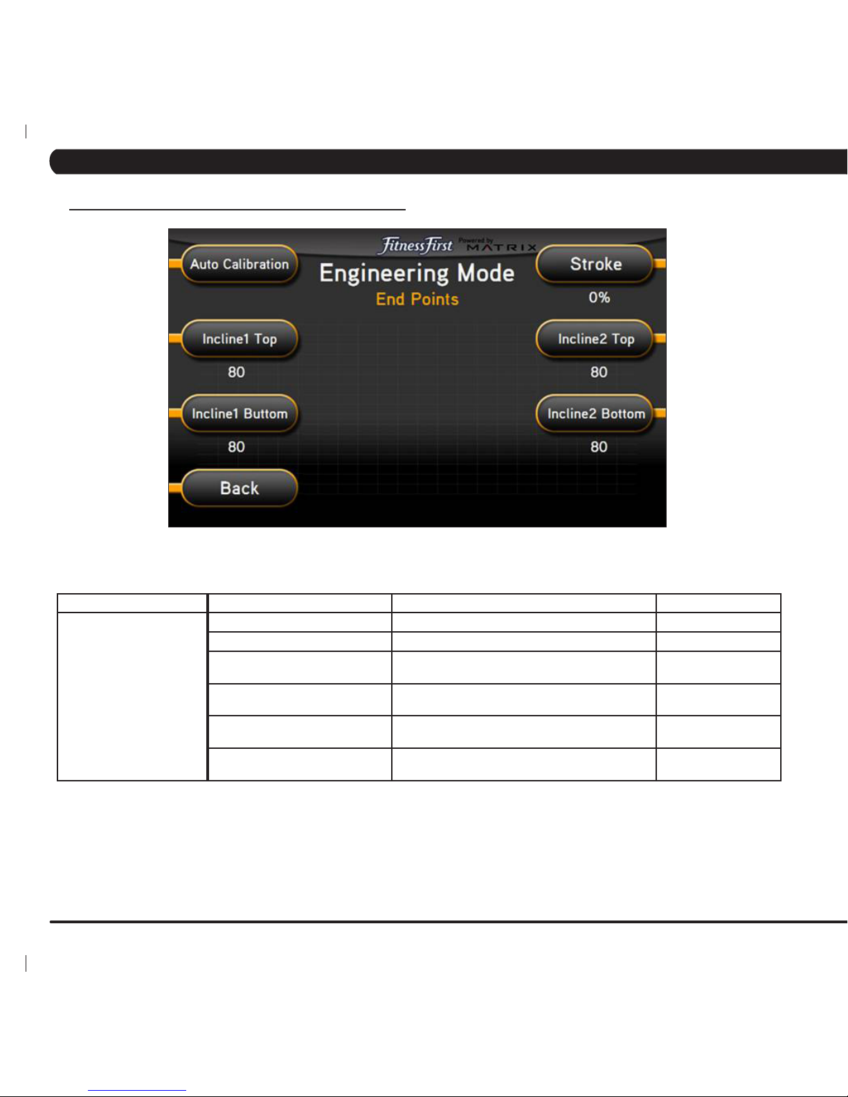
20
FUNCTION & DEFAULTS DESCRIPTIONS MODIFIED
Auto Calibration This option calibrates the elevation parameters. N/A
InclineStroke% Factory Setting Only N/A
Tune Incline 1 Top
Top: 98.5
Sets the maximum incline for incline motor 1. Top: 74.5 - 99.9
Tune Incline 1 Bottom
Bottom: 1.5
Sets the minimum incline for incline motor 1. Bottom: 0.1 - 25.5
Tune Incline 2 Top
Top: 98.5
Sets the maximum incline for incline motor 2. Top: 74.5 - 99.9
Tune Incline 2 Bottom
Bottom: 1.5
Set the minimum incline for incline motor 2. Bottom: 0.1 - 25.5
ENGINEERING MODE
End Points
6.2 ENGINEERING MODE - CALIBRATION TAB
CHAPTER 6: ENGINEERING MODE
Page 25
21
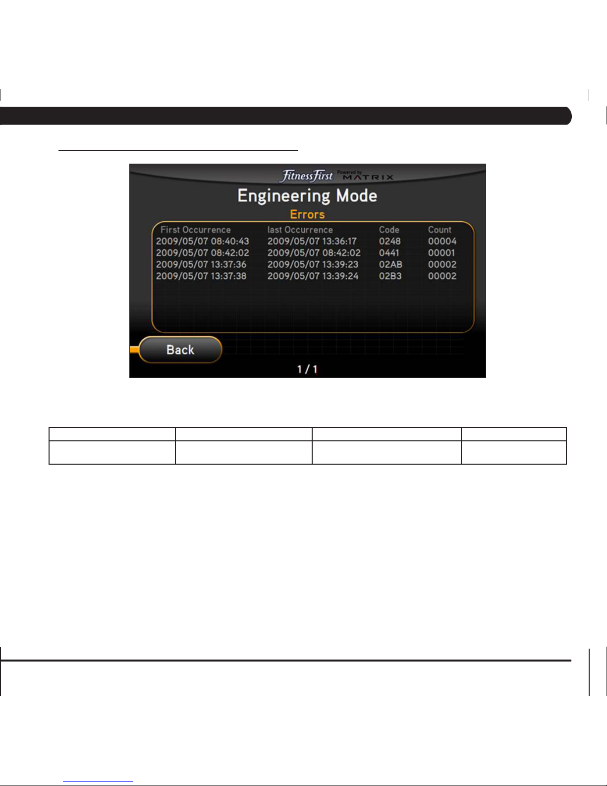
ENGINEERING MODE FUNCTION & DEFAULTS DESCRIPTIONS MODIFIED
Errors This option displays the error code
history.
N/A
6.3 ENGINEERING MODE - ERRORS TAB
CHAPTER 6: ENGINEERING MODE
Page 26
22
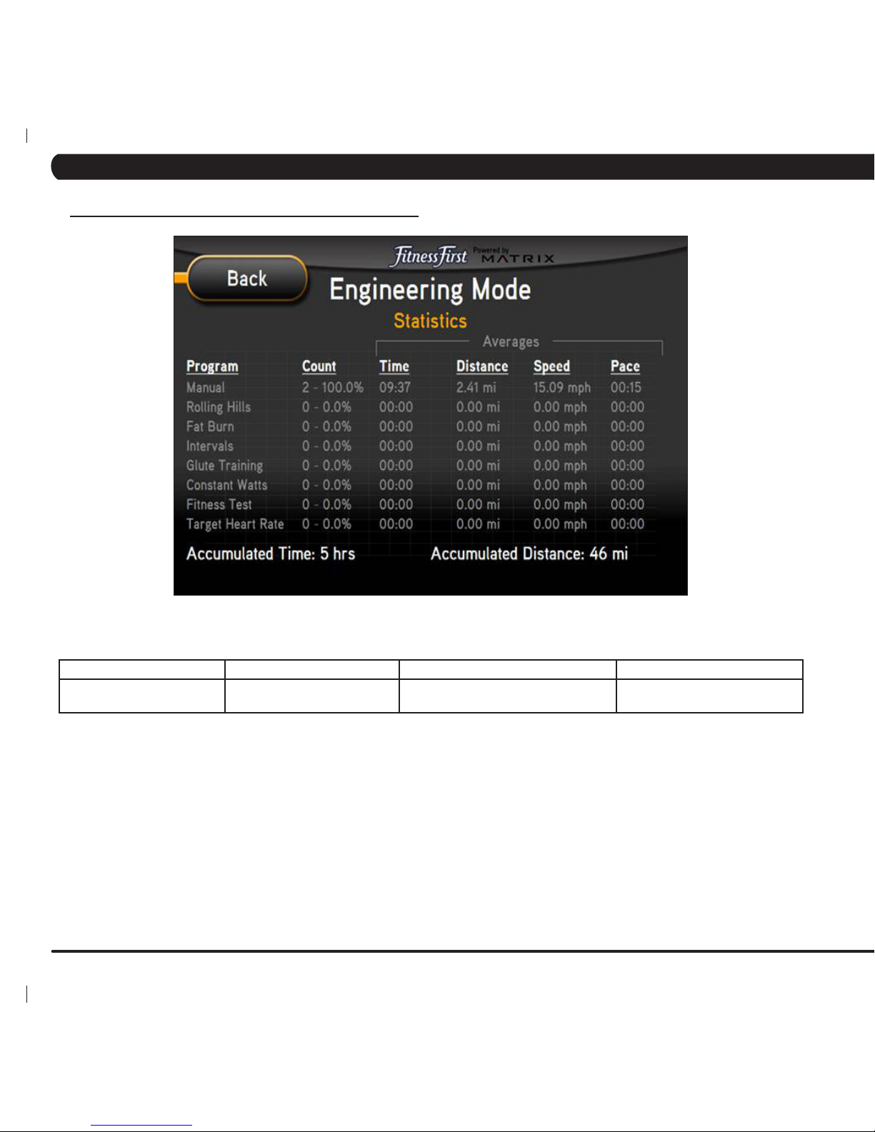
ENGINEERING MODE FUNCTION & DEFAULTS DESCRIPTIONS MODIFIED
Statistics This option displays the workout
information for the unit.
N/A
6.4 ENGINEERING MODE - STATISTICS TAB
CHAPTER 6: ENGINEERING MODE
Page 27
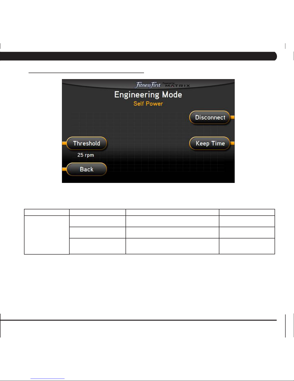
23
FUNCTION & DEFAULTS DESCRIPTIONS MODIFIED
Threshold
Default: 25 RPM
This option controls the minimum RPM limits for
operation.
25 - 60 RPM
Disconnect This option controls the minimum RPM limit to
operate other functions when no power is present.
20 - 60 RPM
Keep Time This option controls how long the console keeps
information after the minimum RPM threshold is not
met.
Home: 60 Seconds
Run: 30 Seconds
Summary: 30 Seconds
ENGINEERING MODE
Self Power
6.5 ENGINEERING MODE - SELF POWER TAB
CHAPTER 6: ENGINEERING MODE
Page 28

24
ENGINEERING MODE FUNCTION & DEFAULTS DESCRIPTIONS MODIFIED
Clubs
Default: MATRIX
This option allows the club to select a screen
header from a list.
N/A
6.6 ENGINEERING MODE - CLUBS TAB
CHAPTER 6: ENGINEERING MODE
Page 29

25
ENGINEERING MODE FUNCTION & DEFAULTS DESCRIPTIONS MODIFIED
Club ID This option records the Club ID of
the fitness facility.
N/A
6.7 ENGINEERING MODE - CLUB ID TAB
CHAPTER 6: ENGINEERING MODE
Page 30
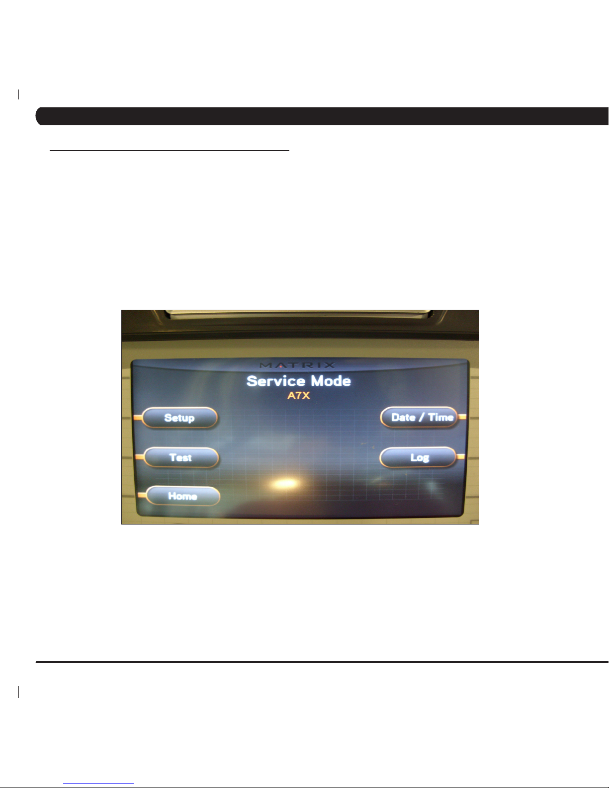
26
The Service Mode allows an authorized service provider to test and store information on the Ascent Trainer.
1) To enter Service Mode, press ENTER, 3, 0, 0, 1, ENTER on the upper display. Service Mode will appear on the display (Figure A).
2) Select the key next to the setting that needs to be changed, and follow the prompts to change.
3) Press the ENTER key once the desired setting is correct to save.
4) Press HOME or press and hold the STOP key for 3-5 seconds to return to normal operation.
FIGURE A
7.1 SERVICE MODE OVERVIEW
CHAPTER 7: SERVICE MODE
Page 31
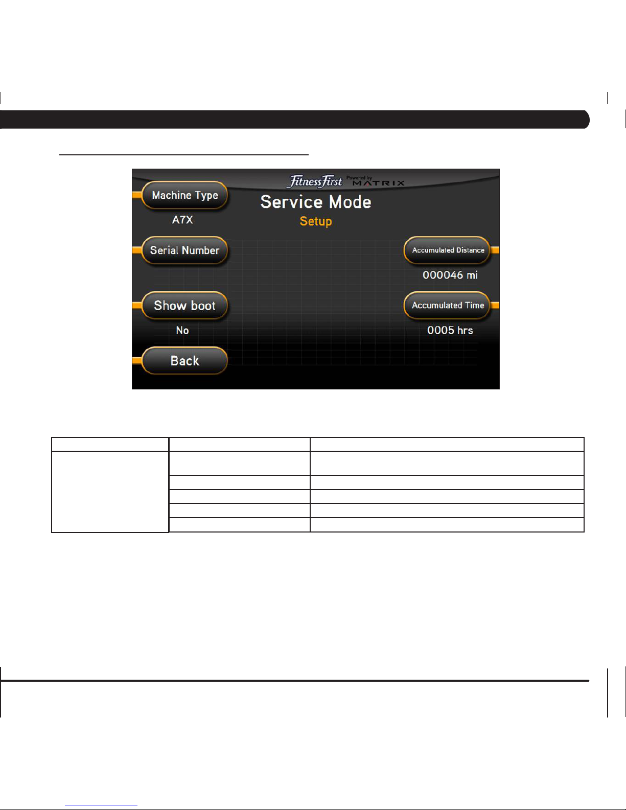
27
FUNCTION & DEFAULTS DESCRIPTIONS
Machine Type
Default: Ascent Trainer
This option selects the current model.
Serial Number This option displays the serial number of the console and frame.
Accumulated Distance This option displays the accumulated workout distance since production.
Accumulated Time This option displays the accumulated workout time since production.
Show Boot Factory Setting Only.
SERVICE MODE
Setup
7.2 SERVICE MODE - SETUP TAB
CHAPTER 7: SERVICE MODE
Page 32

28
FUNCTION & DEFAULTS DESCRIPTIONS
Keypad This option is for a keypad test.
TV Keypad This option turns the TV keypad power on / off.
Auto Calibration This option auto calibrates the lift motors.
SERVICE MODE
Test
7.3 SERVICE MODE - TEST TAB
CHAPTER 7: SERVICE MODE
Page 33

29
SERVICE MODE FUNCTION & DEFAULTS DESCRIPTIONS
Time Date & Time This option sets the current date and time on
the machine.
7.4 SERVICE MODE - DATE & TIME TAB
CHAPTER 7: SERVICE MODE
Page 34

30
7.5 SERVICE MODE - LOG TAB
FUNCTION & DEFAULTS DESCRIPTIONS
Delete This option deletes key components replacement
history.
Create This option creates key components replacement
history.
SERVICE MODE
Log
CHAPTER 7: SERVICE MODE
Page 35

31
8.1 ELECTRICAL DIAGRAM
CONSOLE SYSTEM BLOCK
CHAPTER 8: TROUBLESHOOTING
Page 36

32
CHAPTER 8: TROUBLESHOOTING
8.2 LCB ERROR INDICATORS
LED DESCRIPTION
LED 1 +5V Power LED
LED 2 +32V Power LED
LED 3 This light should PULSE when coummunication with LCB is normal.
LED 4 - 5 LED4ONandLED5OFF=ClassBerrorpresent.
LED4OFFandLED5ON=ClassCerrorpresent.
LED4andLED5ON=Noresistanceoffset.
LED 6 Incline motor 1 up.
LED 7 Incline motor 1 down.
LED 8 Incline motor 2 up.
LED 9 Incline motor 2 down.
LED 10 PWM Signal LED.
Page 37

33
8.3 CONSOLE ERROR CODES
CHAPTER 8: TROUBLESHOOTING
CODE DESCRIPTION SOLUTION
0x0140 When the UCB implements an incline command, there is no
movement after 3 seconds.
Replace the LCB or Incline Motor.
0x0142 Theinclinepositionhasadifferenceofover3%andisnotreduced
within 3 seconds.
Look for misalignment of the Incline
Motors, replace if needed.
0x0441 When the UCB implements a command, the LCB is not receiving. Check the console cable connections,
replace the LCB or UCB as needed.
0x01A0 Incline motor disconnected. Check the connection of the incline
motor cables at the LCB. Replace the
incline motors or LCB as needed.
0x01A1 Incline calibration is over 80 seconds or does not complete. Replace the LCB or Incline Motor
0x01A7 The incline is short circuited or over current. Look for misalignment of the Incline
Motors, replace if needed.
0x01AC ECB has an open circuit, short circuit, or the current is over 2.3
Amps for 1.4 seconds.
Replace the ECB.
0x01AE The battery charge is over current or short circuited. Replace the battery.
0x01AF Resistance or solenoid circuit. Check the generator and resistor.
0x02AB Machine type error. Set the console for Ascent Trainer.
0x02B3 Resistance type error. Check the amperage of the ECB,
replace if needed. If ok, replace the
LCB.
0x02B4 Resistance Type Error Verify that the LCB and UCB software
versions are correct.
Replace the LCB if needed.
0x03A5 Failed to Load Program. Usually means that the file is corrupt.
The software should be re-loaded, or if
necessary the console can be replaced.
0x03A6 Failed to Run Program. Usually means that the file is corrupt.
The software should be re-loaded, or if
necessary the console can be replaced.
0x04A0 If the LCB does not return a message to the UCB within 3 seconds. Check the console cable connections,
replace the LCB or UCB as needed.
0x04B0 UCB no communication response. Check the connection of the console
cable at the UCB and LCB. Replace
the console cable, UCB, or LCB as
needed.
Page 38

34
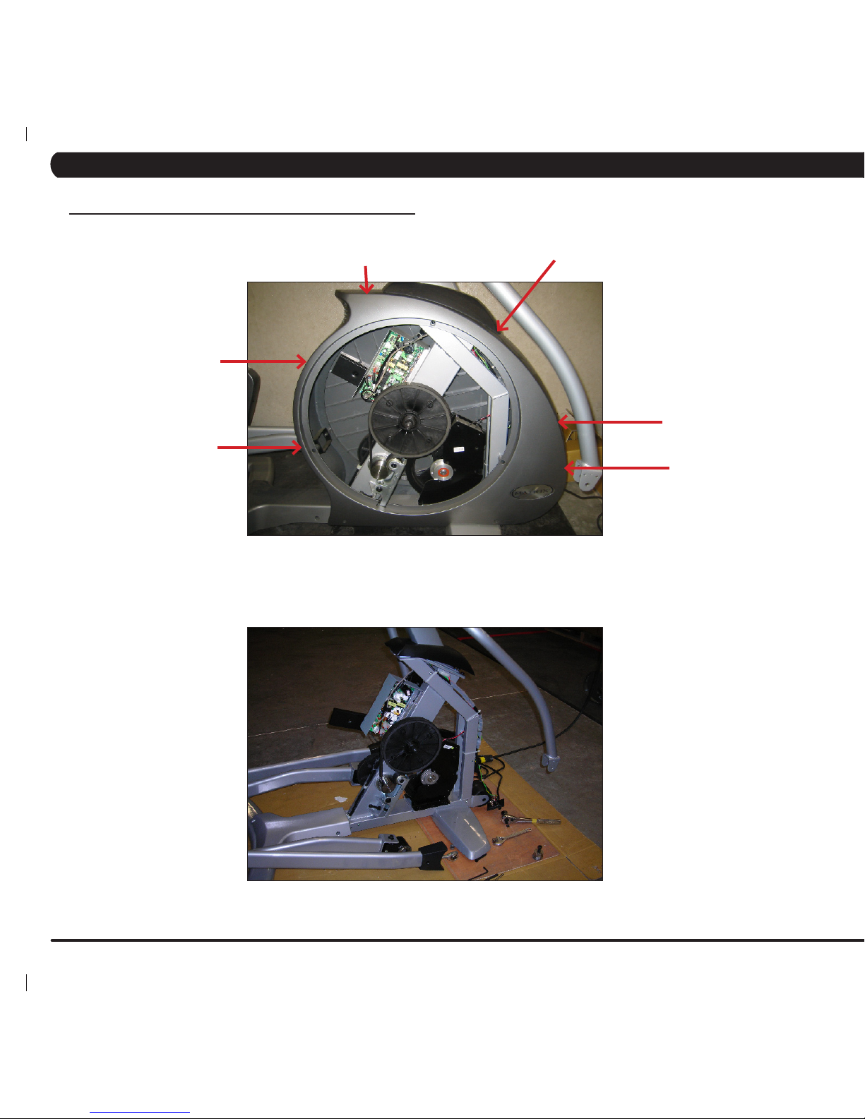
8.4 TROUBLESHOOTING ISSUES
UNIT DOES NOT RECORD DISTANCE OR RPM
1) If the unit resets after 30 seconds despite pedaling, verify that
"Incline reset" is in the ON position in Manager Mode.
2) Select another program and begin pedaling. Look for RPM on
the display. If this is the issue, replace the console.
3) Remove the right side disk and check that the green LED
labeled RPM on the lower control board flashes when the main
drive pulley is turned.
a. If the LED does not flash, check that there are 4 magnets
on the pulley.
b. If the LED still does not flash, verify that the speed sensor
cable is plugged into the lower control board. If the sensor is
plugged into the board, unplug it and perform a continuity check on
the sensor wire. Replace the speed sensor if needed.
5) If all tests have been performed and the issue is still present,
replace the lower control board.
UNIT DOES NOT POWER UP
1) Verify that the unit is plugged in and that there is power at the
outlet (120 v AC). Verify that there is a green LED lit on the power
converter brick. Replace the power converter if needed.
2) Verify the power switch is in the ON position. If there is power
at the power converter and the power switch is in the ON position,
remove the entertainment port plate and check continuity on the
power switch. Replace the switch if needed.
3) Remove the right side disk and check the power LED on the
lower control board (labeled RL). If the LED is not lit, check that the
console communication cable is plugged into the LCB. Check for
power at the lower communication cable, replace if needed.
4) Remove the console and unplug the RJ45 console
communication cable. Measure voltage at the white and blue wires,
it should be 12 Volts. Replace the communication cable if needed.
5) If all test have been performed and the issue is still present,
replace the console.
NO OR HIGH HEART RATE
NOTE: Contact (hand grip) heart rate takes approximately 15
seconds to acquire. Due to variations to physiology, some people
take longer and there is a small percentage of the population that
will not be able to register a heart rate. Contact heart rate grips
work better when the users hands are warm and slightly damp.
1) Remove the HR handlebar assembly from the console mast.
Check continuity on the left hand harness plug. If the reading is 0,
replace the HR wiring.
2) Disassemble the HR grips and check the upper and lower
contact plates for leads. If damaged or corroded, replace the HR
grips.
3) Remove the console and disassemble the front from the back.
Verify that the HR power harness is securely plugged into J6. If all
connections are good, replace the console.
CHAPTER 8: TROUBLESHOOTING
Page 39

35
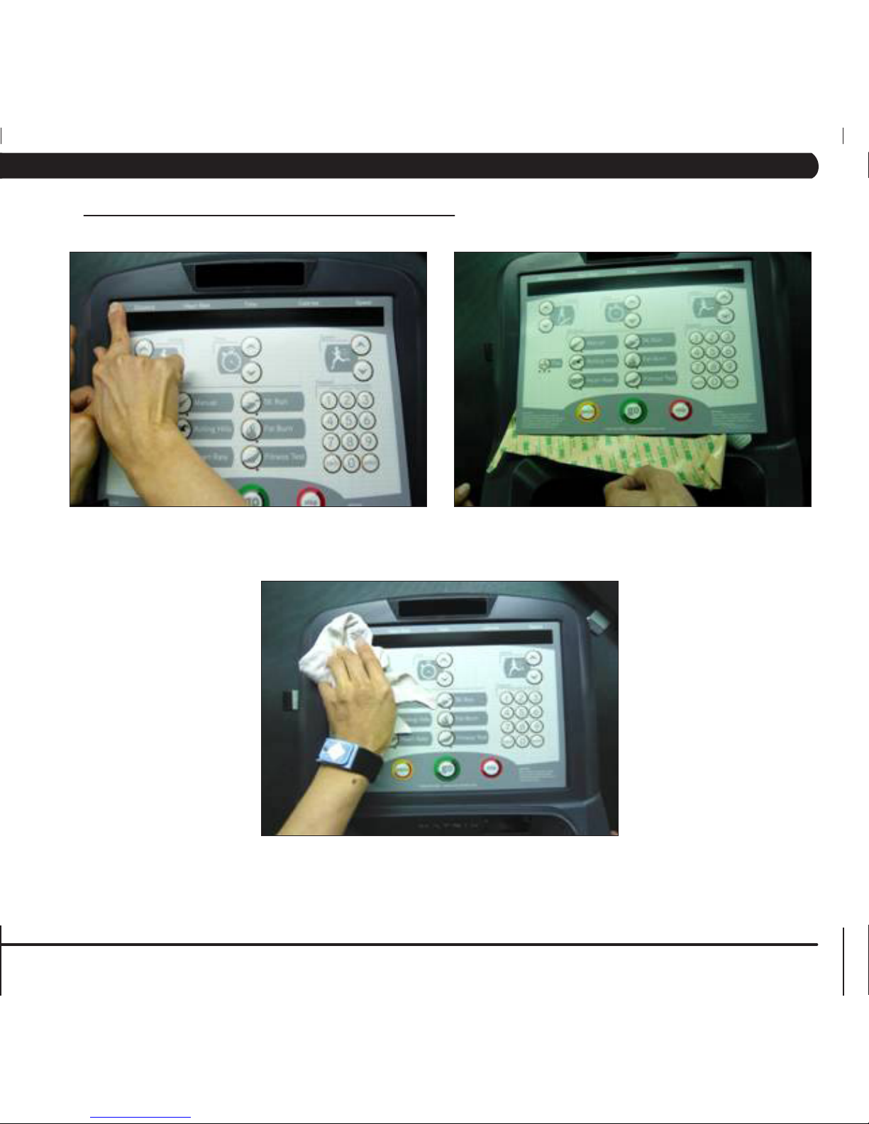
8.5 TROUBLESHOOTING - ENTERTAINMENT KEYPAD ISSUES
CHAPTER 8: TROUBLESHOOTING
PROBLEM:
The entertainment keypad is not recognizing the correct keys.
SOLUTION:
1) Perform a keypad test. To do so:
a. Press ENTER, 3, 0, 0, 1, ENTER on the upper keypad to enter Service Mode.
b. Press the key next to TEST on the display.
c. Press the key next to KEYPAD on the display.
d. The entertainment keypad can now be tested. Press various keys to see if the console is recognizing the correct keys (Figure A). If
not, proceed to Step 2.
2) There are 2 different entertainment keypads available for the A7x Ascent Trainer. To change which key sequence is utilized:
a. Press ENTER, 3, 0, 6, 0, ENTER on the upper keypad.
b. The console should chime twice.
c. Re-test the entertainment keypad, it should now recognize the correct keys.
Page 40

36
1) This section will help with diagnosing problems with the integrated screen TV for the Matrix A7x Ascent Trainer.
2) The TV should have power whenever the unit is powered up. If the TV will not power up when the power button is pressed:
a) Press ENTER, 3, 0, 0, 1, ENTER on the lower number keypad. Press the key next to TEST. Check to make sure that it says
INCLUDE POWER next to the TV Keypad option. If it is excluded, change to include power and retry the TV power.
b) If the TV Keypad option is correct and the TV still will not power up, replace the console.
3) For a fuzzy or unclear picture, see the TV programming instructions in Section 10.5. If the TV is still fuzzy or unclear after programming:
a) Check the coax connection at the entertainment port (Figure A).
b) Remove the 4 screws holding the console to the console mast and check the coax connection at the console (Figure B).
c) Move the coax cable to directly plug into the back of the console bypassing the entertainment port. If this resolves the issue, replace
the internal coax cable.
d) If plugging the coax cable into the back of the console does not resolve the issue, check the coax cable with a known working
television. If the coax cable is good, replace the console.
FIGURE A
FIGURE B
8.6 TV TROUBLESHOOTING - OVERVIEW
CHAPTER 8: TROUBLESHOOTING
Page 41

37
1) Remove the link arm and pedal arm plastic caps (Figures A and B).
2) Detach the dual-action handlebar at the pedal arm (Figure C).
3) Detach the link arm from the crank bearing assembly (Figure D).
FIGURE A
FIGURE B
FIGURE C
FIGURE D
9.1 FRONT DISK REPLACEMENT
CHAPTER 9: PART REPLACEMENT GUIDE
Page 42
38
9.1 FRONT DISK REPLACEMENT
CHAPTER 9: PART REPLACEMENT GUIDE
FIGURE E
4) Rest the link arm padded surface on the front stabilizer (Figure E).
5) Press the center cap and turn it counter clockwise to remove (Figure F).
6) Remove the 24mm locking nut and washer by turning them counter clockwise (Figure G).
FIGURE F
FIGURE G
Page 43

39
9.1 FRONT DISK REPLACEMENT – CONTINUED
CHAPTER 9: PART REPLACEMENT GUIDE
FIGURE H FIGURE I
FIGURE J
FIGURE K
7) Thread the Matrix disk removal tool into the center hub (Figures H and I). Note: There are two different removal tools. If you have 3
tapped holes on your center hub see Figure I, if the inside of the hub
is tapped (no holes) see Figure H.
8) Turn the center bolt of the removal tool clockwise until the main disk can be removed (Figures J and K). Repeat if necessary for the opposite
side disk.
9) Reverse Steps 1-8 to install a new front disk. note: When reinstalling the 24mm nut, it should be tightened to 196 N-m Torque.
Page 44
40
9.2 FRONT SHROUD REMOVAL
CHAPTER 9: PART REPLACEMENT GUIDE
1) Remove the front disks as outlined in Section 9.1.
2) Remove the 6 screws that hold the front shrouds in place on each side (Figure A).
3) Remove the front shrouds for frame access (Figure B).
FIGURE A
FIGURE B
Page 45

41
9.3 LOWER CONTROL BOARD REPLACEMENT
CHAPTER 9: PART REPLACEMENT GUIDE
1) Turn off the power and disconnect the cord from the machine.
2) Remove both front disks from the machine as outlined in Section 9.1.
3) Remove the 2 screws holding the cover on the lower control board to allow wiring access. (Figure A).
4) Disconnect all wires from the LCB (7 connections) (Figure B).
5) Remove the 2 screws holding the LCB to the frame and remove the LCB. (Figure C).
6) Reverse Steps 1-5 to install a new LCB.
7) Test the Ascent Trainer for function as outlined in Section 9.19.
FIGURE A FIGURE B
FIGURE C
Page 46

42
9.4 ECB (ELECTRONIC BRAKE) REPLACEMENT
CHAPTER 9: PART REPLACEMENT GUIDE
1) Turn off power and disconnect the cord from the machine.
2) Remove the front disks as outlined in Section 9.1.
3) Remove the front shrouds as outlined in Section 9.2.
4) Unplug the ECB (under mast connection point) from the wire harness (Figures A & B).
5) Loosen the 11mm nut on the tension loop bolt (Figure C).
6) Remove the tension loop bolt from the ECB bracket. (Figure D).
FIGURE A FIGURE B
FIGURE C
FIGURE D
Page 47

43
9.4 ECB REPLACEMENT – CONTINUED
CHAPTER 9: PART REPLACEMENT GUIDE
FIGURE E FIGURE F
FIGURE G FIGURE H
7) Remove the 6 bolts holding the ECB to the frame & remove the belt once loosened (Figure E).
8) Remove the old ECB and install the new ECB from the user’s left side of the frame. (Figure F).
9) Install the 6 frame mounting bolts loosely & attach the belt. (Figure G).
10) Attach the tension loop bolt to the ECB bracket and tension the belt to 120 lbs using an 11mm nut (Figure H).
11) Tighten the 6 frame mounting bolts to 12 N-m torque.
12) Reconnect the ECB wires, reassemble the front disks and shrouds.
13) Test the Ascent Trainer as outlined in Section 9.19. .
Page 48

44
CHAPTER 9: PART REPLACEMENT GUIDE
9.5 ECB BELT REPLACEMENT
1) Turn off the power and disconnect the cord from the machine.
2) Remove the front disks from the machine as outlined in Section 9.1.
3) Loosen the 6 bolts holding the ECB to the frame (Figure A).
4) Loosen the 11mm nut on the tension loop bolt until there is enough slack in the belt to remove it (Figure B).
5) Install the replacement belt and reverse necessary steps to secure the assembly until the belt is tight. Tighten the 6 ECB bolts to 12 N-m
torque. Tighten the ECB belt to 120 lbs.
6) Test the Ascent Trainer for function as outlined in Section 9.19. .
FIGURE A
FIGURE B
Page 49

45
CHAPTER 9: PART REPLACEMENT GUIDE
9.6 DRIVE BELT REPLACEMENT
1) Turn off the power and disconnect the cord from the machine.
2) Remove the front disks from the machine as outlined in Section 9.1.
3) Loosen the belt tension bolt on the left side of the tension pulley and rotate the pulley counter-clockwise until there is enough slack in the belt
to remove it (Figures A & B).
4) Install the replacement belt and reverse necessary steps to secure the assembly until the belt is tight. Tighten the drive belt to 180 lbs. for a
new belt, 150 lbs. for a used belt.
5) Test the Ascent Trainer for function as outlined in Section 9.19.
FIGURE A FIGURE B
Page 50

46
9.7 PULLEY AXLE SET REPLACEMENT
CHAPTER 9: PART REPLACEMENT GUIDE
1) Turn off the power and disconnect the cord from the machine.
2) Remove both front disks from the machine as outlined in Section 9.1.
3) Loosen the belt tension bolt on the right side until there is enough slack to remove the drive belt and tensioner (Figures A & B).
4) Release any bent tabs on the lock washer around the nut. Remove the 75mm nut from the assembly being serviced (Figure C). Shown with
special tool available from Matrix Fitness.
5) Remove the tapered split ring that is held in place by the nut (Figure D).
6) Remove the bearing assembly, and clean any debris from the frame (Figure E).
7) Reverse steps 1-6 to install a new pulley axle set, making sure to tighten the 75mm nut to 100 N-m torque and rebend the lock washer tabs to
secure the nut. Reinstall the belts as outlined in Sections 9.5 and 9.6.
8) Test the Ascent Trainer for function as outlined in Section 9.19.
FIGURE A
FIGURE B
FIGURE C FIGURE D FIGURE E
Page 51

47
9.8 DRIVE AXLE SET REPLACEMENT
CHAPTER 9: PART REPLACEMENT GUIDE
1) Turn off the power and disconnect the cord from the machine.
2) Remove the front disks from the machine as outlined in Section 9.1.
3) Remove both belts as outlined in Sections 9.5 & 9.6.
4) Release any bent tabs on the lock washer around the nut. Remove the 75mm nut from the assembly being serviced (Figure A). Shown with
special tool available from Matrix Fitness.
5) Remove the tapered split ring that is held in place by the nut (Figure B).
6) Remove the drive axle set and clean any debris from the frame (Figure C).
7) Reverse steps 1-6 to install a new drive axle set, making sure to tighten the 75mm nut to 100 N-m torque and rebend the lock washer tabs to
secure the nut. Reinstall the belts as outlined in Sections 9.5 and 9.6.
8) Test the Ascent Trainer for function as outlined in Section 9.19.
FIGURE A FIGURE B
FIGURE C
Page 52

48
9.9 CONSOLE REPLACEMENT
CHAPTER 9: PART REPLACEMENT GUIDE
1) Turn off the power and disconnect the cord from the machine.
2) Remove the 4 screws that hold the console to the top of the console mast (Figure A).
3) Disconnect the data cable, heart rate, and ground wires and remove the console (Figure B).
4) Reconnect the wire connections to the new console.
5) Carefully push the wires into the console and mast until they are clear of the console/mast connection and attach the console to the mast
using the 4 screws removed in Step 2.
6) Test the Ascent Trainer for function as outlined in Section 9.19.
FIGURE A
FIGURE B
Page 53

49
note: The instructions below are for console overlays / keypads, but the procedure is the same regardless of where the overlay / keypad is.
1) Turn off power and disconnect the cord from the machine.
2) Remove the console as outlined in Section 9.9.
3) Remove the back cover of the console (Figure A).
4) Unplug and remove the faulty overlay (Figure B).
5) Clean the console area with alcohol to remove any left over adhesive (Figure C).
6) Remove the protective film over the display window of the overlay (Figure D).
9.10 OVERLAY & KEYPAD REPLACEMENT
FIGURE A FIGURE B
FIGURE C FIGURE D
CHAPTER 9: PART REPLACEMENT GUIDE
Page 54

50
FIGURE E FIGURE F
FIGURE G
7) Peel part of the protective film from the back of the overlay (Figure E).
8) Push the overlay ribbon cable through the hole in the console and plug it in (Figure F).
9) Match the overlay to the cutout on the console (Figure G).
9.10 OVERLAY / KEYPAD REPLACEMENT - CONTINUED
CHAPTER 9: PART REPLACEMENT GUIDE
Page 55
51
9.10 KEYPAD & OVERLAY REPLACEMENT - CONTINUED
FIGURE H FIGURE I
FIGURE J
CHAPTER 9: PART REPLACEMENT GUIDE
10) Press down on the corners of the overlay to keep it in place, then remove the protective film (Figure H & I).
11) Once the overlay is in the correct position, press down on the overlay with a cloth to adhere it to the console plastic (Figure J).
12) Use the same procedure to replace any additional faulty overlays. note: Overlays can not be reused.
13) Test the Ascent Trainer for function as outlined in Section 9.20.
Page 56

52
9.11 HANDLEBAR ASSEMBLY REPLACEMENT
CHAPTER 9: PART REPLACEMENT GUIDE
1) Turn off the power and disconnect the cord from the machine.
2) Remove the two screws holding the plastic handlebar cover in place and remove the cover (Figure A).
3) Remove the 4 bolts that hold the handlebar to the console mast (Figure B).
4) Pull the handlebar away from the console mast to expose the HR grip wiring (Figure C).
5) Carefully remove the wires from inside the console mast until the connectors on the ends come free and disconnect (Figure D).
6) To install a new handlebar assembly, connect the new handlebar and carefully push the heart rate wires into the console mast.
7) Attach the new handlebar assembly to the console mast using the 4 screws removed in Step 3.
8) Reattach the cover over the handlebar assembly.
9) Test the Ascent Trainer for function as outlined in Section 9.19.
FIGURE A FIGURE B
FIGURE C
FIGURE D
Page 57

53
9.12 REAR SHROUD REPLACEMENT
CHAPTER 9: PART REPLACEMENT GUIDE
1) Remove the 3 screws on the outer shroud (1 at the rear of the machine and 2 at the front) (Figure A).
2) Remove the 6 screws on the inner shroud (Figure B).
3) Remove the shrouds from the machine. (Figure C).
4) Repeat the same steps for the other side of the machine.
5) Reverse steps 1-4 to install new shrouds.
6) Test the Ascent Trainer for function as outlined in Section 9.19.
FIGURE A
FIGURE B
FIGURE C
Page 58

54
9.13 INCLINE MOTOR REPLACEMENT
CHAPTER 9: PART REPLACEMENT GUIDE
1) Turn off the power and disconnect the cord from the machine.
2) Remove the rear shrouds as outlined in Section 9.11.
3) Disconnect the incline motor ground wire from frame. (Figure A).
4) Carefully remove the two 8mm bolts that hold the swing arm to the motor assembly (Figure B).
5) Secure the swing arm as once the bolts are removed it will fall (Figure C)
6) Move the swing arm up to rest against the frame so it is clear of the motor.
7) Remove the motor by disassembling the pivot bolt (Figure D).
FIGURE A
FIGURE B
FIGURE DFIGURE C
Page 59

55
9.13 INCLINE MOTOR REPLACEMENT - CONTINUED
CHAPTER 9: PART REPLACEMENT GUIDE
FIGURE E FIGURE F
FIGURE G FIGURE H
8) Disconnect the wire connection (Figure E).
9) Prepare the new motor for installation, the new motor will have the nut placed at the end of the screw shaft – DO NOT move the nut (Figure F).
10) Install the new motor using the plastic washers (Figure G).
11) Reverse Step 6 to secure the new incline motor in place, and then reconnect the ground wire from step 2. NOTE: Do not overtighten the pivot
bolt – the incline motor must be able to swivel.
12) Reconnect the power cord and turn the machine on. Follow the procedure in Section 4.8 to calibrate the lift motors. As long as calibration
passes, turn off the power and continue to Step 11.
13) Set the nut on the Acme screw to a distance of 67mm from the base of the motor casing to the furthest end of the nut (Figure H).
14) Reattach the swing arm to the nut with 8mm bolts by reversing Step 4.
15) Reinstall the rear shrouds.
16) Test the Ascent Trainer for function as outlined in Section 9.19.
Page 60

56
9.14 DUAL ACTION HANDLEBAR REPLACEMENT
CHAPTER 9: PART REPLACEMENT GUIDE
1) Remove the plastic cover where the dual action handlebar meets the pedal arm (Figure A).
2) Remove the bolt and bushings where the dual action handlebar and the pedal arm meet (Figure B).
3) Remove the two bolts holding the dual action handlebar to the console mast pivot (Figure C).
4) Remove the pivot cap and handlebar (Figure D).
5) Reverse steps 1-4 to install a new dual action handlebar.
6) Test the Ascent Trainer for function as outlined in Section 9.19.
FIGURE A
FIGURE B
FIGURE C FIGURE D
Page 61

57
9.15 FOOT PEDALS REPLACEMENT
CHAPTER 9: PART REPLACEMENT GUIDE
1) Remove the 4 Phillips screws that hold the plastic foot pedal to the foot plate (Figure A).
2) Remove the plastic foot pedal (Figure B).
3) Remove the rubber grip (Figure C).
4) Clean the foot plate to remove any rubber or debris (Figure D).
5) Reverse Steps 1-4 to install a new foot pedal.
6) Test the Ascent Trainer as outlined in Section 9.19.
FIGURE A FIGURE B
FIGURE C FIGURE D
Page 62

58
9.16 PEDAL ARM REPLACEMENT
CHAPTER 9: PART REPLACEMENT GUIDE
1) Remove the plastic cover where the dual action handlebar meets the pedal arm (Figure A).
2) Remove the bolt and bushings where the dual action handlebar and the pedal arm meet (Figure B).
3) Remove the pedal as outlined in Section 9.15.
4) Remove the 3 bolts that hold on the mounting plate at the link arm / pedal arm joint (Figure C). Note the plastic washer that mounts at the end
of the shaft.
5) Slide the pedal arm shaft out of the link arm housing noting the order of the washers on the pedal arm shaft (Figure D).
6) Reverse Steps 1-5 to install a new pedal arm.
7) Test the Ascent Trainer for function as outlined in Section 9.19.
FIGURE A FIGURE B
FIGURE C FIGURE D
Page 63

59
9.17 LINK ARM REPLACEMENT
CHAPTER 9: PART REPLACEMENT GUIDE
1) Remove the plastic cover at the joint of the link arm and the crank assembly (Figure A).
2) Disconnect the link arm from the crank assembly (Figure B).
3) Disconnect the pedal and link arm from the rear of the machine by separating the joint between the swing arm and the link arm. Remove the
plastic cap from the swing arm bushing to reveal the bolt and washer that hold the joint together. Remove the bolt (tighten to 28 N-m torque during
reassembly) (Figures C & D).
FIGURE A
FIGURE B
FIGURE D
FIGURE C
Page 64
60
9.17 LINK ARM REPLACEMENT - CONTINUED
CHAPTER 9: PART REPLACEMENT GUIDE
FIGURE E FIGURE F
FIGURE G FIGURE H
4) The swing arm can now be separated from the pedal arm (Figure E).
5) Remove the 3 bolts that hold on the mounting plate at the link arm / pedal arm joint (Figure F).
6) Note the plastic washer that mounts at the end of the shaft, this will needed during re-assembly (Figure H).
7) Slide the pedal arm shaft out of the link arm housing noting the arrangement of the washers on the pedal arm shaft. (Figure I).
8) Reverse Steps 1-7 to install a new link arm.
9) Test the Ascent Trainer for function as outlined in Section 9.19.
Page 65

61
9.18 SWING ARM REPLACEMENT
CHAPTER 9: PART REPLACEMENT GUIDE
1) Remove the black plastic cover on the lower swing arm joint (Figure A).
2) Remove the bolt that holds the swing arm to the pedal and link arms (Figure B).
3) Carefully tap the crank arm inward until it can be pulled free of the bearing housing (Figure C & D).
4) Loosen one of the bolts on either side of the upper pivot joint (Figure E).
FIGURE A FIGURE B
FIGURE C
FIGURE D FIGURE E
Page 66

62
9.18 SWING ARM REPLACEMENT - CONTINUED
CHAPTER 9: PART REPLACEMENT GUIDE
FIGURE F FIGURE G
FIGURE H FIGURE I
5) Holding onto the swing arm, push / pull the pivot shaft out of the bearing housing (Figures F and G).
6) Transfer the rubber arm pad and plastic parts to the new swing arm. (Figure H).
7) Reverse Steps 1-6 to install the new swing arm. note: Be aware of the spacer between the bearings that the shaft passes through (Figure I).
8) Test the Ascent Trainer for function as outlined in Section 9.19.
Page 67

63
9.19 REAR PIVOT ARM REPLACEMENT
CHAPTER 9: PART REPLACEMENT GUIDE
1) Turn off the power and disconnect the cord from the machine.
2) Remove the rear shrouds as outlined in Section 9.11.
3) Remove the bolts holding the rear pivot arm to the incline motor (Figure A).
4) Remove the 4 bolts that hold the upper pivot arm assembly to the lower pivot arm (Figure B) and carefully swing the upper arm assembly
forward and out of the way.
5) Remove the pivot shaft bolt and taper washer from the pivot assembly (Figures C).
6) Remove the pivot shaft and rear pivot arm from the frame (Figure D).
7) Reverse Steps 1-6 to install a new pivot arm assembly. note: Tighten the pivot shaft bolt to 40 N-m torque.
8) Test the Ascent Trainer for function as outlined in Section 9.19.
FIGURE A FIGURE B
FIGURE D
FIGURE C
Page 68

64
9.20 TESTING THE ASCENT TRAINER
ONCE THE UNIT OR REPLACEMENT PART IS FULLY INSTALLED AND ASSEMBLED AND
PROPERLY PLACED ON THE FLOOR, USE THE FOLLOWING INSTRUCTIONS TO TEST
THE MACHINE:
1) Check that the console is set for Ascent Trainer.
a. Press ENTER, 3, 0, 0, 1, ENTER on the keypad to enter Service Mode.
b. Press the key next to SETUP on the display.
c. Press the key next to MACHINE TYPE on the display.
d. Press the key next to ASCENT TRAINER on the display.
e. Press the BACK and HOME keys or press and hold the STOP key for 3-5 seconds to return to normal function.
2) Enter the serial number of the frame into the console. To do so:
a. Press ENTER, 3, 0, 0, 1, ENTER on the number keyapd, Service Mode will appear on the display.
b. Press the key next to SETUP on the display.
c. Press the key next to SERIAL NUMBER on the display.
d. Press the key next to PLATFORM on the display.
e. Enter the last 8 digits of the serial # from the base frame of the unit (see Section 1.1 for serial number location).
f. Press the key next to OK on the display to save the serial number.
g. Press the BACK and HOME keys or press and hold the STOP key for 3-5 seconds to return to normal function.
3) Without hitting start or entering any exercise modes, stand on the machine and hold the handlebars while initiating movement to simulate
exercising. While moving listen for any odd noises or squeaks.
4) After stopping movement, press the green GO key and begin using the machine.
5) Grasp the hand grips to check for proper heart rate response.
6) Press the LEVEL UP and DOWN keys both on the hand grips and on the console to make sure resistance is fully functional.
7) Press the ELEVATION UP and DOWN keys (fully incline and decline the machine) to make sure the incline motor function is fully operational.
8) If the Ascent Trainer has had an incline motor replaced, or if this is the initial installation, calibrate the lift motors (see Section 4.8).
CHAPTER 9: PART REPLACEMENT GUIDE
Page 69

65
10.1 ASCENT TRAINER SPECIFICATIONS
CONSOLE
Display Type 7" LCD
Display Feedback Time, Distance, Calories, Calories per hour, Speed, Incline, Heart
Rate, METs, Watts, Level, RPM, Profile
Programs Manual, Rolling, Intervals, Fat Burn, Glute Training, Fitness Test,
Target HR, Constant Watts
Resistance Levels 25
Elevation Levels 20
Multi-language Display Yes - English, German, French, Italian, Spanish, Dutch, Portuguese,
Chinese, Japanese
CSafe, FitLinxx Ready Ye s
Integrated Vista Clear™ Digital Ready TV Yes - 7" Screen Size
Wireless Data Transmitter Yes
iPod Compatible Yes
Nike + iPod Compatible Yes
Personal Fan Yes
TECHNICAL DATA
Resistance Technology JID Hybrid ECB
Power Requirements0 Powered 120V / 60Hz AC
Minimum Watts 16
Overall Dimensions (L x W x H) 80" x 34.5" x 72" / 203.2 x 87.7 x 182.9 cm
Maximum User Weight 400 lbs / 181.4 kg
Unit Weight 396 lbs / 179.2 kg
Shipping Weight 435 lbs / 196.9 kg
Transport Wheel Yes
USER DATA
Stride Length 21-24"
Incline Range 30"
Contact Heart Rate Sensors Ye s
Telemetric Heart Rate Receiver Yes
Cushioned Footpads Yes
Q-Factor 3.75"
Handle Bar Design Multi-position dual action and ergo bend stationary.
Thumb Switch Controls Yes
CHAPTER 10: ASCENT TRAINER SPECIFICATIONS AND ASSEMBLY GUIDE
Page 70
66
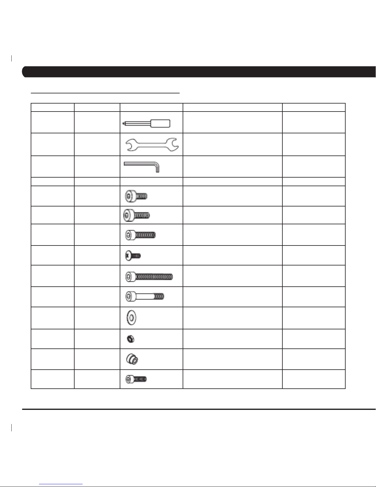
10.2 FASTENERS & ASSEMBLY TOOLS
QUANTITY PART # SKETCH DESCRIPTION PACKAGE COLOR
01 Z11 PHILLIPS SCREWDRIVER PURPLE
01 Z12
13 MM OPEN WRENCH PURPLE
01 Z13 6 MM ALLEN WRENCH PURPLE
04 Z01 HEX SOCKET HEAD CAP (M8 X 15L) YELLOW
02 Z14 HEX SOCKET HEAD CAP (M8 X 25L) YELLOW
08 Z02 HEX SOCKET HEAD CAP (M8 X 20L) BLACK
06 Z03 CROSS TRUSS HEAD (M5 X 10L) WHITE
04 Z04 HEX SOCKET HEAD CAP (M8 X 65L) WHITE
02 Z05 HEX SOCKET HEAD CAP (M8 X 55L) WHITE
02 Z06 FLAT WASHER (8.2 X 16.0 X 1.0T) WHITE
02 Z07 NYLON NUT (M8 X 1.25P) WHITE
04 Z08 AXLE WHITE
05 Z41 SOCKET HEAD CAP SCREW (M5 X 8L) WHITE
CHAPTER 10: ASCENT TRAINER SPECIFICATIONS AND ASSEMBLY GUIDE
Page 71

67
10.3 ASCENT TRAINER ASSEMBLY STEPS
STEP 1
CHAPTER 10: ASCENT TRAINER SPECIFICATIONS AND ASSEMBLY GUIDE
Page 72

68
STEP 2
10.3 ASCENT TRAINER ASSEMBLY STEPS - CONTINUED
CHAPTER 10: ASCENT TRAINER SPECIFICATIONS AND ASSEMBLY GUIDE
Page 73

69
STEP 3
10.3 ASCENT TRAINER ASSEMBLY STEPS - CONTINUED
CHAPTER 10: ASCENT TRAINER SPECIFICATIONS AND ASSEMBLY GUIDE
Page 74

70
10.3 ASCENT TRAINER ASSEMBLY STEPS - CONTINUED
FINAL ASSEMBLY
CHAPTER 10: ASCENT TRAINER SPECIFICATIONS AND ASSEMBLY GUIDE
Page 75

71
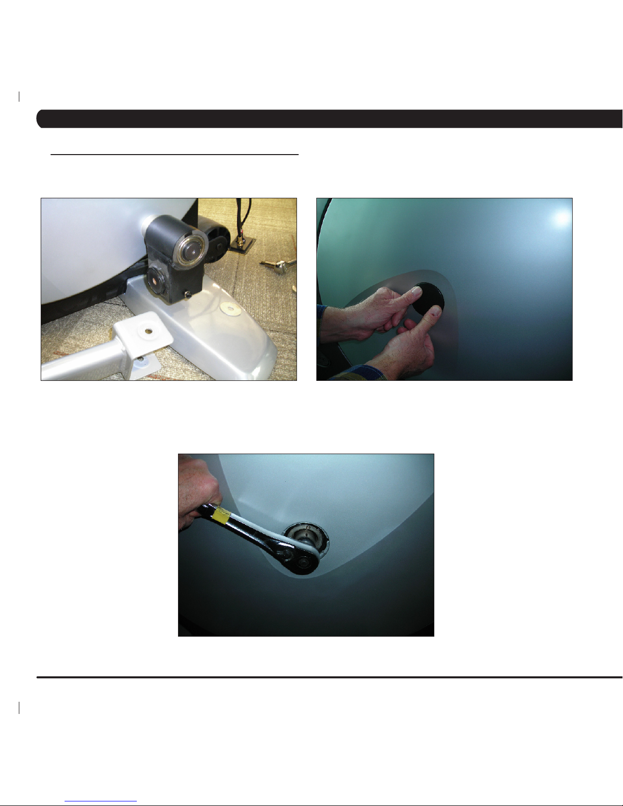
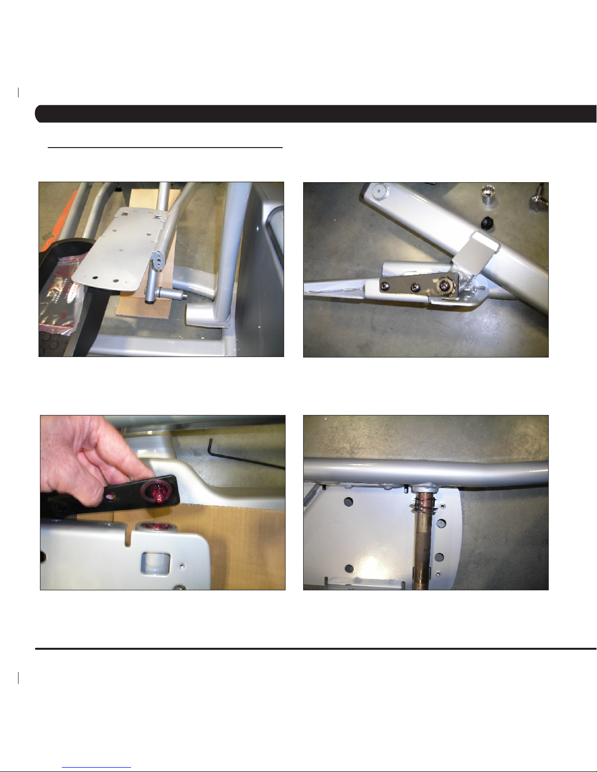
10.4 STABILIZING THE ASCENT TRAINER
stabiliZinG tHe matriX a7X-01 ascent trainer
On a new Ascent Trainer, the rubber foot on the underside of the center of the frame should be flush against the frame itself. The rubber foot
has a washer that eliminates pressure against the nut that is inside the frame. This rubber foot needs to be screwed in all the way (Figure A),
and is not used for adjustments.
All stability adjustments are made using the front stabilizer leveling feet (Figure B). Most of the time you will be raising the front of the machine
instead of lowering it. Raise the front of the unit until you can fit a piece of paper underneath the rubber foot on the center of the frame (Figure
C). Once you have both feet set to a level position, use a 14mm or 17mm wrench (depending on which stabilizing feet you have) to tighten the
jam nut and secure the feet (Figure D).
FIGURE A
FIGURE B
FIGURE C
FIGURE D
CHAPTER 10: ASCENT TRAINER SPECIFICATIONS AND ASSEMBLY GUIDE
Page 76

72
1) Press ENTER, 1, 0, 0, 1, ENTER on the number keypad on the upper display and Manager Mode will appear on the display.
2) Press the key next to TV (Figure A), and then press the key next to CHANNEL SCAN (Figure B).
3) Press the - key on the number keypad and a Menu will appear on the TV (Figure C).
4) Use the volume keys to move horizontally in the Menu and the channel keys to move up or down. note: You must press buttons quickly in
the Menu or it will minimize within 5 seconds.
5) Move the cursor over to Channel on the top right of the Menu (Figure D).
FIGURE A FIGURE B
FIGURE C
FIGURE D
10.5 TV PROGRAMMING INSTRUCTIONS
CHAPTER 10: ASCENT TRAINER SPECIFICATIONS AND ASSEMBLY GUIDE
Page 77

73
FIGURE E FIGURE F
FIGURE G FIGURE H
10.5 TV PROGRAMMING INSTRUCTIONS - CONTINUED
CHAPTER 10: ASCENT TRAINER SPECIFICATIONS AND ASSEMBLY GUIDE
6) Then go down to CHANNEL SCAN and use the volume button to select it (Figure E).
7) Move the cursor down to START TO SCAN and use the volume button to select it (Figure F).
8) If the channels are now coming in clearly, press the BACK key to return to normal operation (Figure G).
9) If the channels still are not coming in, or are showing in black and white, return to CHANNEL SCAN, and then change the CABLE SYSTEM
to match your incoming cable frequency (Figure H). Re select START TO SCAN once this has been changed.
10) If the channels are still not coming in clearly, refer to the TV Troubleshooting in Section 8.5.
Page 78

74
Bearing replacement procedure for Ascent Trainer machines.
11.1 BELT TENSIONER BEARING REPLACEMENT
1. Replacement bearing kit (SAP - 0000086250)
RE-WORK PARTS REQUIRED
1. Replacement bearing kit (SAP - 0000086250)
2. (2) 5mm Allen Wrench
3. Phillips head screwdriver
4. 24mm Socket Wrench
5. Matrix Disc Removal Tool
TOOLS AND EQUIPMENT REQUIRED
1. Refer to Ascent Trainer Service Manual and complete steps 1,2
and 3 in Section 9.5 or 9.6.
2. With the drive belt loosened, remove the tension wheel assembly
from the unit using a 5mm Allen Wrench (Figure A).
3. Remove the bearing and washers from the assembly housing with
5mm Allen Wrenches (Figure B).
4. Check to see if the housing needs the washers included in the kit.
Usethewasherstollanyexcessgapbetweenthenewbearing
andbracket.Ifthebearingtswithminimalgapthendiscardthe
washers. DO NOT USE JUST ONE WASHER. This will cause a
misalignment with the belt. When using both washers, it will be a
snugt.Ifyouneedhelpaligningthewashersandbearingtothe
holes in the housing, use a screwdriver to nudge the bearing.
5. Secure the new bearing with the 2 hex screws (Figure C).
6. Install the bearing assembly onto the unit and reverse steps 1,2,
and 3 in Section 9.5 or 9.6.
7. Test the Ascent Trainer for function as outlined in Section 9.20.
PROCEDURE
FIGURE A
FIGURE B
FIGURE C
CHAPTER 11: UPGRADES
Page 79

75
11.2 BEARING ASSEMBLY SHIMMING
Eliminate clunking noise by shimming bearing assembly with washers.
1. Washer kit (SAP - ZMS3000335): Includes 4x .1mm
(SAP-ZMS3000332)and4x.2atwashers(SAP-ZMS3000333),
2x. 5mm wavy washer (SAP 005219-00).
RE-WORK PARTS REQUIRED
1. Snap Ring Pliers
2. Phillips Head Screwdriver
3. 8mm Socket
4. 17mm Open Wrench
TOOLS AND EQUIPMENT REQUIRED
1. Remove the plastic guard cover over the crank assembly with a
Phillips head screwdriver (Figure A).
2. Separate the bearing assembly from the arm using an 8mm
socket and 17mm open wrench (Figure B).
3. Remove the snap ring from the bearing rod using a snap ring
pliers (Figure C).
4. Remove the bearing assembly from rod (Figure D).
5. Insert the appropriate combination of washers onto the rod. This
number will vary, but using combinations of washers you may go up
to .1mm in total shim distance. Typically you should start with a .2
mm washer and adjust from there.
6. Do a stress test by trying to move the bearing assembly back and
forth along the rod. If the assembly still moves, add washers in .1mm
increments.until tight.
7. Test the Ascent Trainer for function as outlined in Section 9.20.
PROCEDURE
FIGURE A
FIGURE B
FIGURE C
FIGURE D
CHAPTER 11: UPGRADES
Page 80

76
11.3 UPGRADING HANDGRIPS WITH RESISTANCE BUTTONS
Replacement instructions for the resistance level buttons that are
handle bar mounted to the Ascent Trainer.
1. Each kit includes: Complete left and right hand grip components.
RE-WORK PARTS REQUIRED.
1. #2 Phillips Head Screwdriver
2. Straight Blade Screwdriver
TOOLS AND EQUIPMENT REQUIRED
BEFORE BEGINNING PLEASE NOTE THAT YOU REMOVE AND
REPLACE KEYPADS WITH LIKE ARROW DIRECTIONS ON
EACH SIDE DURING THE REPLACEMENT PROCESS.
1. Remove the bottom grip plate using a straight blade screwdriver
(Figure A). NOTE: The grip plate and plastic grip will probably be
damaged or destroyed in the removal process, these parts are all
included in the upgrade kit.
2. Remove the three (3) Phillips head screws that hold the two
halves of the plastic grip together (Figure B).
3. Separate the two halves of the hand grip (Figure C) and
disconnect the wires from the grip plates, and unplug the wire from
the circuit board (Figure D).
4. Connect the wire to the top grip plate of the new grips, and install
the grip plate by pressing it into place in the handle (be sure to
remove all of the protective wrapping from the new grip plate and
plastic).
5. Connect the wire to the circuit board of the new handle, and set
this half of the handle in place on the machine.
6. Using the screws provided in the updated kit, set the bottom
portion of the plastic handle in place and fasten the two halves
together being sure to hook the wire to the bottom grip plate.
7, Test the Ascent Trainer for function as outlined in Section 9.20.
PROCEDURE
FIGURE A
FIGURE B
FIGURE C
FIGURE D
CHAPTER 11: UPGRADES
Page 81

77
11.4 INSTALLING ADJUSTABLE TENSIONER
Replaces the belt tensioner with an adjustable bracket assembly.
RE-WORK PARTS REQUIRED
1. Part # 0000089133 (short - this is used on most units) or
0000089456 (long) - Replacement Tensioner Kit: contains tensioner
assembly, zip ties, and shims.
2. Part # 0000089129 - Adjustment Block. Send one per technician
(can be reused on multiple units).
TOOLS AND EQUIPMENT REQUIRED
1. 24 mm Socket / Ratchet.
2. Matrix Wheel Puller.
3. Torque Wrench to 2000kgf*cm/196 N-m (145 ft*lbf).
4. #2 Phillips Head Screwdriver.
5. 5 mm, 6 mm, and 8 mm Allen / Hex.
6. 13 mm / 17 mm Open End Wrench.
7. Pliers.
8. Side Cutter.
PROCEDURE
1. Read these directions all the way through before proceeding.
2. Follow the procedure outlined in Section 9..1 of the Ascent
Trainer Service Manual to remove the right side disc from the
machine.
3. Loosen the belt tension lock nut with a 17mm wrench, and back
off the screw so that the drive belt can be removed from the unit.
Remove the locking nut to allow more room to fit the parts in later
steps.
4. Use a 5 mm Allen wrench to remove the tensioner from the
machine. NOTE: Several of the Phillips screws will need to be
removed so the plastic covers can be spread far enough to remove
the tensioner completely from the mounting post.
5. If required, remove the non-crowned tension roller from the old
assembly and move it to the new assembly. Rollers that have a
crowned face or rollers consisting of two bare ball bearings are to be
replaced with the new roller kit.
6. Check the 5 screws on the tensioner assembly. They should be
only lightly finger tight and the three pieces should all slide freely
against each other without excessive slop.
7. Place the alignment block over the small pulley and then place
the new tensioner onto the frame.
8. Apply pressure across the small pulley and the roller to bring the
two parts into contact with the alignment block.
CHAPTER 11: UPGRADES
Page 82

78
11.4 INSTALLING ADJUSTABLE TENSIONER - CONTINUED
9. Thread the two cable ties through the bottom holes in the
alignment block and around all of the components.
10. Grab the tail end of each cable tie and pull the cable tie VERY
tight, stretching it around the components. As the cable tie is held
tight, push the zipper portion toward the roller to lock the tension in.
11. Grasp the pulley on the opposite side of the machine from the
small pulley and rotate it back and forth slightly to confirm that the
components are all seated tightly against each other.
12. Grasp the pulley on the opposite side of the machine from the
small pulley and rotate this back and forth slightly and gently as
you make these bolts finger-tight. Finger-tighten the 2 bolts on the
bottom of the bracket assembly and then the three bolts on the side.
CHAPTER 11: UPGRADES
Page 83

79
11.4 INSTALLING ADJUSTABLE TENSIONER - CONTINUED
13. Start at the bottom and tighten the Cap Screws (6 mm Hex).,
14. Next, tighten the three hex head screws (13 mm wrench).
15. Cut the cable ties and remove the alignment block from the
machine. Keep the alignment block for the next step.
CHAPTER 11: UPGRADES
Page 84

80
11.4 INSTALLING ADJUSTABLE TENSIONER - CONTINUED
16. Install the drive belt and move the tensioner assembly on the
mounting post until it is centered on the belt. Make a judgement or
measurement of the space between the tensioner mounting block
and the mounting post on each side.
17. Choose shims from the kit to go behind and in front of the
bracket and do a test installation of the tensioner bracket. If
the bracket is not centered choose different shims - repeat as
necessary.
18. Adjust the drive belt tension to 180 lbs. for new belt, 150 lbs. for
used belt.
19. While observing the distance between the belt edge and
tension roller edge, spin the drive in the forward direction several
revolutions. Stop the machine, spin the drive in the reverse
direction and make sure the belt does not change its contact
position on the tensioner wheel as the crank direction is reversed.
It is possible to achieve 0 mm change in many cases but up to 0.5
mm is acceptable.
20. Any significant travel or variance observed when the drive
direction is changed indicates that the tensioner is not properly
aligned and this procedure should be repeated from step 2 until
there is 0 mm to 0.5 mm belt travel observed when the drive
direction is changed back and forth.
Machine with 1 mm or greater shift in position of the belt on the
back side tensioner would experience shortened belt life and noise.
21. Test the Ascent Trainer for function as outlined in Section 9.20.
CHAPTER 11: UPGRADES
Page 85
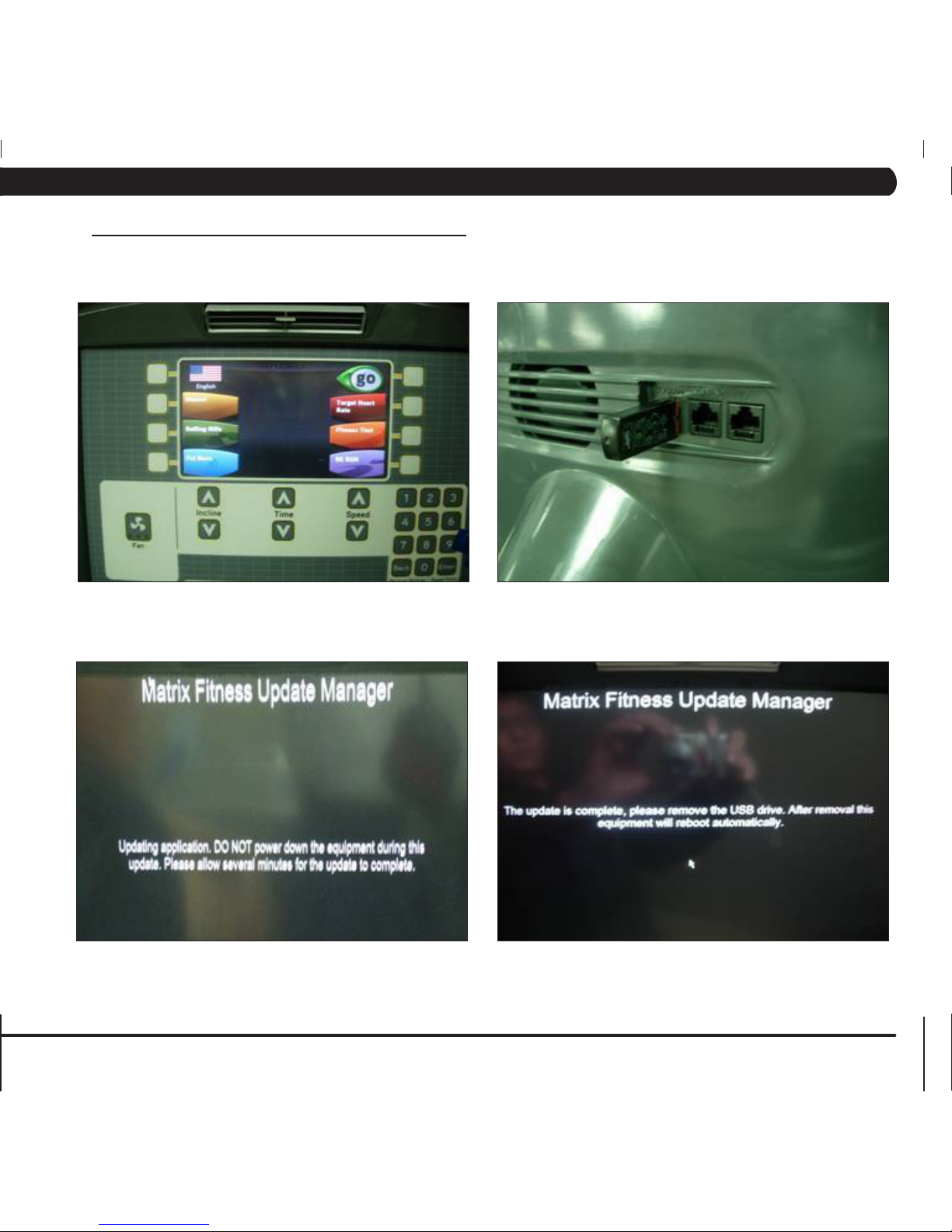
81
12.1 SOFTWARE UPGRADE PROCEDURE
FIGURE A
1) Copy three software files (7x deploy.cab, io.txt, and update.config) onto a USB drive.
2) Turn on the power to the Ascent Trainer, wait until the standby picture has been cleared (Figure A).
3) Insert the USB drive into the Reprogram Port in the back of the console back cover (Figure B).
4) The upgrade procedure will run automatically (Figure C).
5) When the update is complete, the display will prompt to remove the USB drive (Figure D).
6) Power should cycle automatically once the USB drive is removed. Once the unit powers back up, test for function as outlined in Section 9.20.
FIGURE B
FIGURE C FIGURE D
CHAPTER 12: SOFTWARE UPGRADE PROCEDURE
Page 86

82
NOTES
Page 87

83
MATRIX FITNESS SYSTEMS CORP.
1610 LANDMARK DRIVE COTTAGE GROVE WI 53527 USA
TOLL FREE 866.693.4863
www.matrixfitness.com
FAX 608.839.1717
REV. 02
KO
 Loading...