

Page 1

Oscilloscope
USERMANUAL
DualTraceOscilloscope
MembersOfTheFamily
Page 2

CONTENTS
1.GENERAL1
1.1Description1
1.2Features1
2.TECHNICALSPECIFICATIONS2
3.PRECAUTIONSBEFOREOPERATINGTHEOSCILLOSCOPE6
3.lUnpackingtheOscilloscope6
32CheckingtheLinevoltage6
3.3Environment7
3.4EquipmentInstallationandOperation7
3.5CRTIntensity7
3.6WithstandingVoltagesofInputTerminals7
4.OPERATIONMETHOD11
4.1IntroductionofFrontPane111
4.215
4.3BasicOperation-SinglechannelOperation16
4.4Dual-ChannelOperation17
4.5ADDOperation18
4.6Triggering18
4.7TIME/divcontrol21
4.8SweepMagnification21
4.9X-YOperation22
4.10CalibrationofProbe23
5.CURSORREADOUTOPERATION24
5.1ReadOutPanel24
5.2Cursormeasurement25
6.MAINTENANCE30
6.1Fusereplacement30
6.2Cleaning30
7.BLOCKDIAGRAM31
┈┈┈┈┈┈┈┈┈┈┈┈┈┈┈┈┈┈┈┈┈┈┈┈┈┈┈┈┈┈┈┈┈┈┈┈┈┈┈┈┈┈┈┈
┈┈┈┈┈┈┈┈┈┈┈┈┈┈┈┈┈┈┈┈┈┈┈┈┈┈┈┈┈┈┈┈┈┈┈┈┈┈┈┈┈┈
┈┈┈┈┈┈┈┈┈┈┈┈┈┈┈┈┈┈┈┈┈┈┈┈┈┈┈┈┈┈┈┈┈┈┈┈┈┈┈┈┈┈┈┈
┈┈┈┈┈┈┈┈┈┈┈┈┈┈┈┈┈┈┈┈┈┈┈┈┈┈┈┈┈┈┈┈┈┈┈
┈┈┈┈┈┈┈┈┈┈┈┈┈┈┈┈┈┈┈┈┈┈┈
┈┈┈┈┈┈┈┈┈┈┈┈┈┈┈┈┈┈┈┈┈┈┈┈┈┈┈┈┈┈┈┈┈┈┈
┈┈┈┈┈┈┈┈┈┈┈┈┈┈┈┈┈┈┈┈┈┈┈┈┈┈┈┈┈┈┈┈┈┈┈┈
┈┈┈┈┈┈┈┈┈┈┈┈┈┈┈┈┈┈┈┈┈┈┈┈┈┈┈┈┈┈┈┈┈┈┈┈┈
┈┈┈┈┈┈┈┈┈┈┈┈┈┈┈┈┈┈┈┈┈┈┈┈┈┈┈┈┈┈┈
┈┈┈┈┈┈┈┈┈┈┈┈┈┈┈┈┈┈┈┈┈┈┈┈┈┈┈┈┈┈┈┈┈┈┈┈┈┈┈
┈┈┈┈┈┈┈┈┈┈┈┈┈┈┈┈┈┈┈┈┈┈┈┈┈┈┈┈┈┈┈
┈┈┈┈┈┈┈┈┈┈┈┈┈┈┈┈┈┈┈┈┈┈┈┈┈┈┈┈┈┈┈┈┈┈┈┈┈┈┈
┈┈┈┈┈┈┈┈┈┈┈┈┈┈┈┈┈┈┈┈┈┈┈┈┈┈┈┈┈┈┈┈┈┈┈┈
┈┈┈┈┈┈┈┈┈┈┈┈┈┈┈┈┈┈┈┈┈┈┈┈┈┈┈┈┈┈┈┈
┈┈┈┈┈┈┈┈┈┈┈┈┈┈┈┈┈┈┈┈┈┈┈┈┈┈┈┈┈┈
┈┈┈┈┈┈┈┈┈┈┈┈┈┈┈┈┈┈┈┈┈┈┈┈┈┈┈┈┈┈┈┈┈┈┈┈┈
┈┈┈┈┈┈┈┈┈┈┈┈┈┈┈┈┈┈┈┈┈┈┈┈┈┈┈┈┈┈┈┈┈┈┈┈┈┈┈
┈┈┈┈┈┈┈┈┈┈┈┈┈┈┈┈┈┈┈┈┈┈┈┈┈┈┈┈┈┈┈┈┈┈┈┈┈┈┈
┈┈┈┈┈┈┈┈┈┈┈┈┈┈┈┈┈┈┈┈┈┈┈┈┈┈┈┈┈┈┈┈┈┈┈┈┈┈┈
┈┈┈┈┈┈┈┈┈┈┈┈┈┈┈┈┈┈┈┈┈┈┈┈┈┈┈┈┈┈┈┈┈┈┈┈┈┈┈
┈┈┈┈┈┈┈┈┈┈┈┈┈┈┈┈┈┈┈┈┈┈┈┈┈┈┈┈┈┈┈┈┈┈┈┈┈┈┈
┈┈┈┈┈┈┈┈┈┈┈┈┈┈┈┈┈┈┈┈┈┈┈┈┈┈┈┈┈┈┈┈┈┈┈┈┈┈┈
┈┈┈┈┈┈┈┈┈┈┈┈┈┈┈┈┈┈┈┈┈┈┈┈┈┈┈┈┈┈┈┈┈┈
┈┈┈┈┈┈┈┈┈┈┈┈┈┈┈┈┈┈┈┈┈┈┈┈┈┈┈┈┈┈┈┈┈┈┈┈┈┈┈
┈┈┈┈┈┈┈┈┈┈┈┈┈┈┈┈┈┈┈┈┈┈┈┈┈┈┈┈┈┈┈┈┈┈┈┈┈┈┈
┈┈┈┈┈┈┈┈┈┈┈┈┈┈┈┈┈┈┈┈┈┈┈┈┈┈┈┈┈┈┈┈┈┈┈┈┈┈┈
┈┈┈┈┈┈┈┈┈┈┈┈┈┈┈┈┈┈┈┈┈┈┈┈┈┈┈┈┈┈┈┈┈┈┈┈┈┈┈
┈┈┈┈┈┈┈┈┈┈┈┈┈┈┈┈┈┈┈┈┈┈┈┈┈┈┈┈┈┈┈┈┈┈┈┈┈┈┈
┈┈┈┈┈┈┈┈┈┈┈┈┈┈┈┈┈┈┈┈┈┈┈┈┈┈┈┈┈┈┈┈┈┈┈┈┈┈┈
┈
┈┈
┈
┈┈┈┈┈
┈┈┈┈IntroductionofRearPane1
PAGE
ⅱ
SAFETYTERMSANDSYMBOLS
Thesetermsmayappearinthismanualorontheproduct:
WARNING.
!
couldresultininjuryorlossoflife.
!
Thefollowingsymbolsmayappearinthismanualorontheproduct:
Warningstatementsidentifyconditionorpracticesthat
.tCAUTION
Cautionstatementsidenifyconditionsorpracticesthat
couldresultindamagetothisproductorotherproperty.
!
DANGERATTENTIONProtectiveEarth(ground)
HighVoltagerefertoManualConductorTerminal
Terminal
ⅲ
Page 3
1.GENERAL
1.1Description
The620Rfamilyoscilloscopearedual-channeloscilloscopewithmaximumsensitivityoflmV/div.Thetimebaseprovidesa
maximumsweeptimeof0.2uS/div.Whenmagnifiedby10,thesweepspeedis20ns/div.Theverticaldeflectionsystemhas
twoinputchannels.Eachchannelhas12basicdeflectionfactorsfrom5mVt020Vperdivision,itcanexpandedto1mV/div
bypulloutx5MAGbutton.Eachoftheseoscilloscopeemploysa6-inchrectangulartypecathode-raytubewithinternal
graticule.620R/640Rhascursorreadoutfunctionwhichcandisplayvoltage,time,frequencyetc.informationonscreen.
Theseoscilloscopesaresturdy,easytooperateandexhibitshighoperationalreliability.
1.2Features
L)HighintensityCRTwithhighaccelerationvoltage:
TheCRTisahighbeamtransmission,highintensitypewithahighaccelerationvoltageof2KVforand
12KVfor.Itdisplaysclearreadabletracesevenathighsweepspeeds.
640B/650B/640BF/650BF/640R/650R
2)Atriggerlevellockfunctionwhichmakesthetriggeringadjustmentunnecessary.
3)Alternatetriggering:
Evenanobservationoftwowaveformsofdifferentfrequencies,thewaveformoftheeachchannelisstablytriggered.
4)TVsynctriggering:
TheoscilloscopehasasyncseparatorcircuitfortriggeringofTV-VandTV-Hsignals.
5)CHlOutput:
Terminated50ohmoutputofchannel1signalavailableonrearpanelfordrivingfrequencycounterorotherinstruments.
6)Z-AxisInput:
Intensitymodulationcapabilitypermitstimeorfrequencymarkerstobeadded.Traceblankwithpositivesignal,TTL
compatible.
7)X-Yoperation:
SettheswitchtoX-Y.ThentheinstrumentworksasanX-Yoscilloscope.CHlcanbeappliedashorizontaldeflection(X-axis)
whileCH2provideverticaldeflection(Y-axis).
ty BF5620NF/620R
620B/620
1
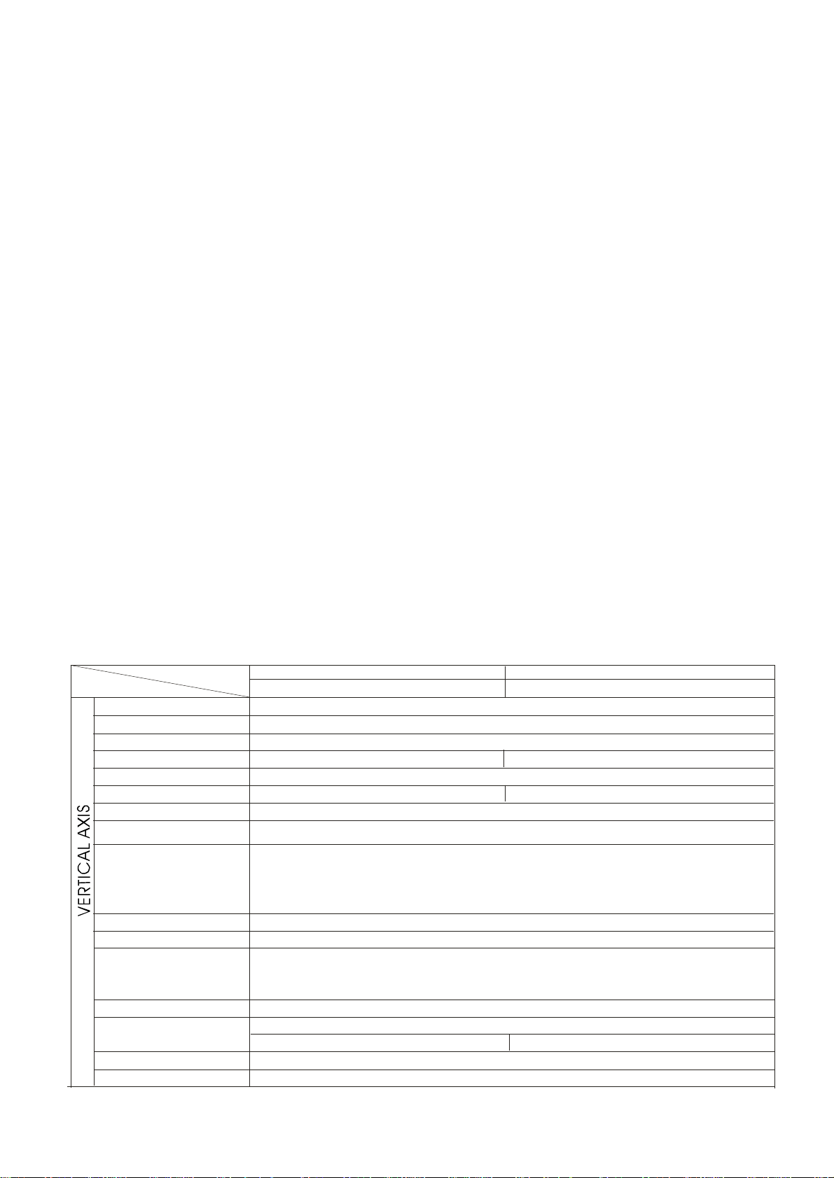
2.TECHNICALSPECIFICATIONS
MODEL
SPECIFICATIONS
Sensitivity
Sensitivityaccuracy
VernierVerticalsensitivity
Frequencybandwidth
Risetime
Inputimpedance
Linearity
Werticalmodes
Choppingrepetitionfrequency
Inputcoupling
Maximuminputvoltage
Commonmoderejectionratio
Isolationbetweenchannels
(At5mV/DIVrange)
CH1signaloutput
CH2INVBAL.
20MHzOSCILLOSCOPE40MHz/50MHzOSCILLOSCOPE
620B/5620NF/620BF/620R640B/650B/640BF/650BF/640R/650R
5mV~20V/DIV,12stepsin1-2-5sequence(5620NF:5mV-5V/DIV,10stepsin1-2-5sequence)
≤≤3%(x5MAG:5%)(5620NF:Devoid)±±
Continuouslyvariabletol/2.5orlessthanpanel-indicatedvalue.
DC~20MHz(x5MAG:DC~7MHz)DC~4OMHz(x5MAG:DC~15MHz)
ACcoupling:Lowlimitfrequency10Hz.(Withreferenceto100KHz,8DIV.Frequencyresponsewith-3dB)
Approx.17.5nS(x5MAG:Approx.50nS)Approx.8.75nS/8.0nS(x5MAG:Approx.50nS)
Approx.lMohm//Approx.25pF
≤± o0.lDIVofamplitudechangewhenwavefrmof2DIVatgraticulecenterismovedvertically.
CHI:CHlsinglechannel.
CH2:CH2singlechannel.
DUAL:CHIandCH2aredisplayed.ALTorCHOPselectableatanysweeprate.
ADD:CH1+CH2algebraicaddition.
Approx.250KHz
AC,GND,DC
400V(DC+ACpeak),AC:frequencylkHzorlower.
Whensetprobeswitchatl:1,themaximumeffectivereadoutis160Vpp(56Vrmsatsinewave),
orsetprobeswitchat10:1,themaximumeffectivereadoutis400Vpp(140Vrmsatsinewave).
50:1orbetterat50KHzsinusoidalwave.(WhensensitivitiesofandCH2aresetequally)CH1
>1000:lat50KHz
>30:lat15MHz>30:1at35MHZ/45MHz
Atleast20mV/DIVintoa50ohmtermination.Bandwidthis50Hztoatleast5MHz.
Balancedpointvariation:1DIV(Referenceatcentergraticule.)≤
(
10°°
C-35C
Tableone
)
2
Page 4

SPECIFICATIONS
Triggeringsource
Triggeringmodes
EXTtriggeringsignalinput
Inputimpedance
Max.inputvoltage
Sweeptimeaccuracy
Verniersweeptimecontrol
Sweepmagnification
x10MAGsweeptimeaccuracy
Positionshiftcausedbyxl0MAG
X-Y
MODE
Frequencybandwidth
X-Yphasedifference
MODEL
Coupling
Slope
Sensitivity.
Sweeptime
Linearity
Sensitivity
(Tableonecontinue)
20MHzOSCILLOSCOPE40MHz/50MHzOSCILLOSCOPE
620B/5620NF/620BF/620R640B/650B/640BF/650BF/640R/650R
CH1,CH2,LINE,EXT(CHlandCH2canbeselectedonlywhentheverticalmodeisDUALorADD.
InALTmode,iftheTRIG.ALTswitchispushedin,itcanbeuseforalternatetiggeringoftwodifferentsource.
AC:20Hztofullbandwidth
+/20Hz~2MHz:1.0DIV;TRIG-ALT:2DIV;EXT:200mV
2~20MHz:1.5DIV
2~20MHz:1.5DIV20-40MHz2.5DIV40~50MHz:3DIV
TRIG-ALT:3DIV,EXT:800mV
TV:Syncpulsemorethanldiv(EXT:lV)
AUTO:Sweepsruninthefreemodewhennotriggeringinputsignalisapplied.
(Applicableforrepetitivesignalsoffrequency25Hzorover.)
NORM:Whennotriggeringsignalisapplied,thetraceisinthereadystateandnotdisplayed.
TV-V:Thissettingisusedwhenobservingtheentireverticalpictureoftelevisionsignal.
TV-H:Thissettingisusedwhenobservingtheentirehorizontalpictureoftelevisionsignal.
(BothTV-VandTV-Hsynchronizeonlywhenthesynchronizingsignalisnegative)
Approx.:lMohm//approx.25pF
400V(DC+ACpeak),AC:FrequencynothigherthanlKHz
0.2uSec~0.5Sec/DIV,20stepsin1-2-5sequence
(10
+/-3%
1/2.5ofpanel-indicatedvalue
≤
°°
)
C-35C
10times
+/-5%(20nSec~50nSecareuncalibrated)
+/-5%,xl0MAG:+/-10%(0.2sand1s)
Within2DIV.atCRTscreencenter
Sameasverticalaxis.(X-axis:CHlinputsignal;Y-axis:CH2inputsignal.)
DCtoatleast500KHz
3atDC~50KHz
≤°
3
SPECIFICATIONS
ZAXIS
CALIBEATION
VOLTAGE
CRT
MODEL
Sensitivity
Frequencybandwidth
Inputresistance
Maximuminputvoltage
Waveform
Frequency
Dutyratio
Outputvoltage
Outputimpedance
Type
Phosphor
Accelerationvoltage
Effectivescreensize
Graticule
Tracerotation
20MHzOSCILLOSCOPE
620B/5620NF/620BF/620R
5Vp-p(Positive-goingsignaldecreasesintensity)
Approx.47Kohm
30V(DC+ACpeak,ACfrequency1kHz)≤
Positive-goingsquarewave
6-inchrectangulartype,internalgraticule
Approx.2kVApprox.12kV
8x10div(1div=10mm(0.39in))
Tableonecontinue
40MHz/50MHzOSCILLOSCOPE
640B/65/640BF/0B650BF/640R/650R
DC~2MHz
Approx.1kHz
Within48:52
2Vp-p 2%
Approx,1Kohm
P31
Internal
Provided
4
Page 5

Cursormeasurementsystem
Cursormeasurement
Function
CURSOR
READOUT
FUNCTION
Cursorresolution
Effectivecursor
Range
Panelsetting
620R/640R/650R
V.1/T.T
P(t,V)
1/25DIV
Vertical:3div±
Horizontal:4div±
Vertical:V/DIV,AC/DC/GND,CH1,CH2,
INV,ALT,CHOP,ADD
Horizontal:TIME/DIV,x10MAG
Trigger:Source,Slope,AUTO,NORM,TV-V/TV-H
Others:probe(x1/x10),X-Y
LinePowerRequirements
Voltage:AC220V/240V10%
(manufactoryset)
Frequency:50Hzor60Hz
Powerconsumption:
Approx..40VA,35W(max.)
±
MechanicalSpecifications
Dimensions:310Wx150Hx455D(mm)
Weight:Approx..8kg(l7.6lbs.)
5
OperatingEnvironment
Indooruse
Altitudeupto2000m
Ambienttemperature:
Tosatisfyspecifications:l0to35C(50to95F)
Maximumoperatingranges:0to40C(32to104F)
Relativehumidity:75%RH(max.)nonCondensing
InstallationCategoryII
Pollutiondegree2
StorageTemperature&Humidity
-10to70C,70%RH(maximum)
Accessories
Powercordl
Usermanual1
Probes2
3.PRECAUTIONSBEFOREOPERATINGTHEOSCILLOSCOPE
3.1UnpackingtheOscilloscope
Theoscilloscopeisshippedfromthefactoryatterbeingful1yinspectedandtested.Uponreceivingtheinstrument,
immediatelyunpackandinspectitforanydamagesthatmighthavebeensustainedduringtransportation.Ifanysignof
damageisfound,immediatelynotifythebearerand/orthedealer.
┈┈┈
┈┈┈
┈┈┈┈┈
3.2CheckingtheLinevoltage
TheseoscilloscopeswilloperateonAC220Vor240Vsettedbymanufatory.BeforeconnectingthepowerplugtoanACline
outlet,makesurethevoltageiscorrectcorrespondingtothelinevoltage.Note:thescilloscopemaybedamagedifitis
connectedtothewrongAClinevoltage.
WARNING.Toavoidelectricalshockthepowercordprotective
!
Replacetherequiredfusesshownbelow.
WARNING.Toavoidpersonalinjudisconnectthepowercord
!
groundingconductormustbeconnectedtoground.
LinevoltageFuse
AC220V250V
AC240V250V
beforeremovingthefuseholder
Range
T0.5A
192~242
T0.5A
216~266
ry,
6
Page 6
3.3Environment
Thenormalambienttemperaturerangeofthisinstrumentis0to40C(32to104F).Operationoftheinstrumentabovethis
temperaturerangemaycausedamagetothecircuits.
Donotusetheinstrumentinaplacewherestrongmagneticorelectricfieldexists,suchfieldsmaydisturbthemeasurement.
3.4EquipmentInstallation,andOperation
Ensurethereisproperventilationfortheholeventsintheoscilloscopecase.
Ifthisequipmentisusedinamannernotspecifiedbythemanufacturer,theprotectionprovidedbytheequipmentmaybe
impaired.
3.5CRTIntensity
TopreventpermanentdamagetotheCRTphosphor,donotmaketheCRTtraceexcessivelybrightorleavethespot
stationaryforanunreasonablylongtime.
3.6WithstandingvoltagesofInputTerminals
Thewithstandingvoltagesoftheinstrumentinputterminalsandprobeinputterminalsareasshowninthefollowingtable.
Donotapplyvoltageshigherthantheselimits.Whensetprobeswitchatl:1,themaximumeffectivereadoutis160Vpp
(56Vrmsatsinewave).Whensetprobeswitchat10:1,themaximumeffectivereadoutis400Vpp(140Vrmsatsinewave).
InputterminalMaximuminputvoltage
CH1,CH2,inputs400VDC+ACpeak
EXTTRLGINinput400VDC+ACpeak
Probeinputs600VDC+ACpeak
()
()
()
ZAXISinput30Vpeak
CAUTION.
donotexceedmaximuminputvoltages.
!
Maximuminputvoltagesmusthave
frequencieslessthan1KHz.
Toavoidinstrumentdamage,
IfanACvoltagewhichissuperimposedonaDCvoltageisapplied,themaximumpeakvalueofCHlandCH2inputvoltages
mustnotexceed+or-300V.SoforACvoltageswithameanvalueofzerovoltthemaximumpeaktopeakvalueis600V.
7
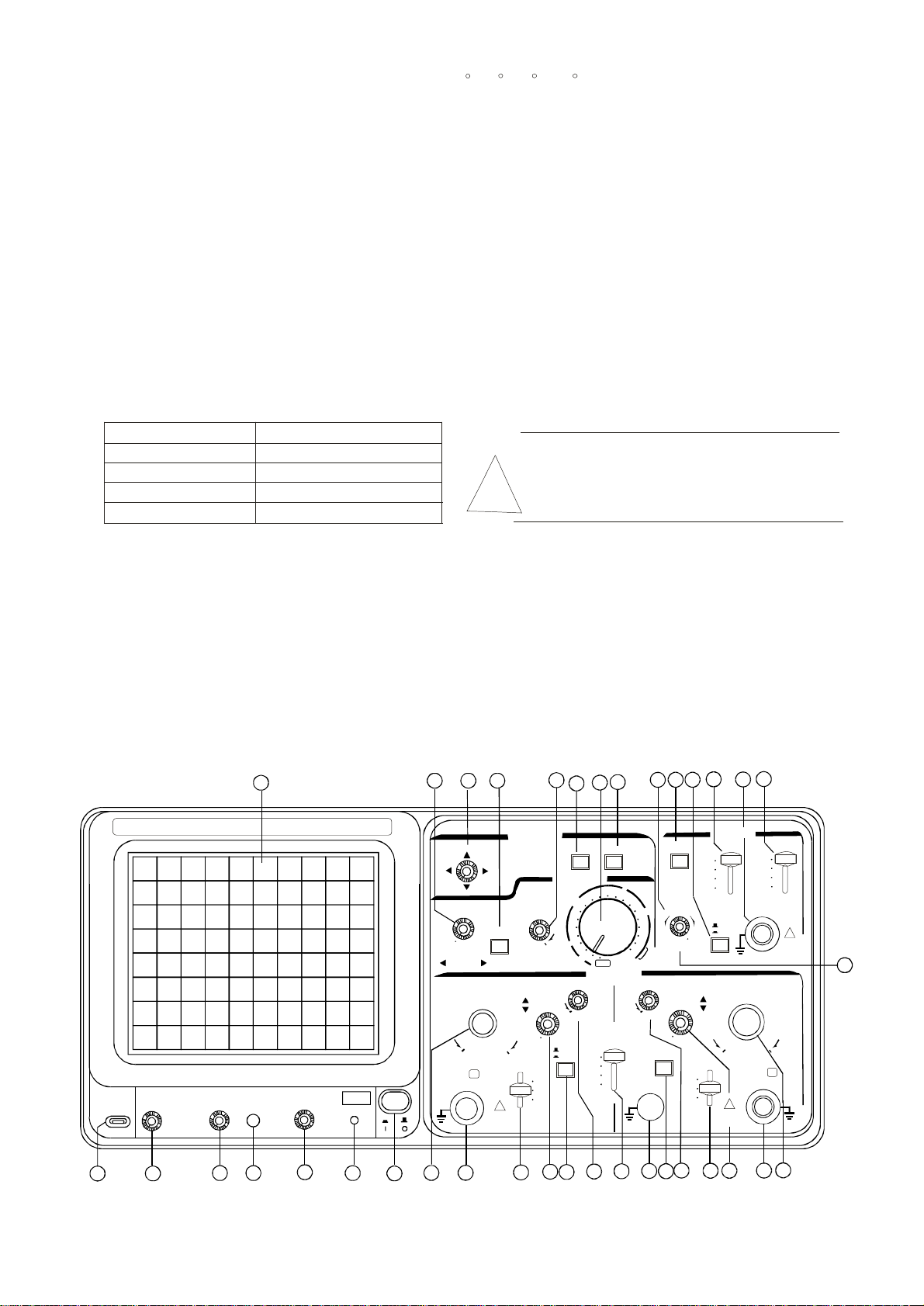
Figure4-1
620R/640R/650RFrontPanel
CAL
2Vp-p
1KHz
INTEN
OSCILLOSCOPE
TRACE
FOCUS
ROTATION
25
26
20
10
uS
5
2
1
.5
.2
UNCAL
VAR
CAL
27
TRIG.ALT
LEVEL
-+
LOCK
x10
POSITION
PULLx5MAG
CH2INV
GND
AC
DC
AUTO
NORM
TV-V
TV-H
SLOPE
20V
35
34
POSITION
VOLTS/DIV
CH1
1M//25pFΩ
X10MAG
X
300V ⅡCAT
MAX.400Vpk
33
!
36
PUSHTRACK
20V
READOUT
INTEN
POWER
32 28
31
READOUT
FUCTIONMENU
HORIZONTAL
TIME/DIV
mS
10
20
50
CAL
VIEWTIME
VAR
POSITION
CAL
PULLx5MAG
ALT
5mV
CHOP
AC
GND
DC
2
5
.1
.2
S
DUAL
30
1
.5
X-Y
VERTICAL
MODE
CH1
CH2
ADD
29
.1.2.5
50
23
24
TRIGGER
MODESOURCE
CH1
CH2
LINE
EXT
TRIGIN
1M//25pFΩ
+
-
VOLTS/DIV
CH2
1M//25pFΩ
!
300V ⅡCAT
MAX.400Vpk
Y
5mV
!
300V
CAT Ⅱ
MAX.
400Vpk
22
12 13
11
1
2
4
3
5
6 7
9
8
10
14 15 16
17
19
18
2021
8
Page 7

Figure4-2
620B/640B/650B/5620NF/620BF/640BF/650BFFrontPanel
36
35
45
33
30
32 28 27
26
25 24
23
OSCILLOSCOPE
888888
POSITION
1
V
2
5
CH1
TRACE
CAL
INTEN
2Vp-p
1KHz
1
2
FOCUS
3
ROTATION
4
POWER
6 7
1M//25pFΩ
9
8
X10MAG
VOLTS/DIV
.5.2.1
10
20
X
300V ⅡCAT
MAX.400Vpk
HORIZONTAL
SWP.VAR.
50
20
mV
10
5
!
10
CAL
POSITION
PULLx5MAG
AC
GND
DC
11
MHz
KHz
ALT
CHOP
12
mS
10
20
50
VAR
CAL
2
5
.1
.2
S
DUAL
TIME/DIV
1
.5
X-Y
VERTICAL
MODE
CH1
CH2
ADD
13
.1.2.5
50
20
10
uS
5
2
1
.5
.2
x10
UNCAL
VAR
CAL
CH2INV
14 15 16
TRIG.ALT
-+
POSITION
PULLx5MAG
LEVEL
LOCK
17
GND
AC
DC
AUTO
NORM
TV-V
TV-H
TRIGGER
MODE
SLOPE
+
-
1
V
2
5
300V ⅡCAT
MAX.400Vpk
18
VOLTS/DIV
.5.2.1
10
20
!
19
CH1
CH2
LINE
EXT
TRIGIN
1M//25pFΩ
5
CH2
1M//25pFΩ
SOURCE
50
20
mV
10
Y
2021
!
300V
CATⅡ
MAX.
400Vpk
22
9
Figure4-3
620R/640R/650RRearPanel
LINEVOLTAGE
SELECTION
220V
240V
POWERMAX.35WATTS,40VA
!
ENSURETHEPOWERISREMOVEDFROM
THEINSTRUMENTBEFOREREPLACINGTHEFUSE
39
RANGE
(50/60Hz)
198~242
216~264
~
AC
40
FUSE
T0.5A
250V
T0.5A
250V
FUSE
41
Z-AXISINPUT
!
30VpkMAX.
!
CH1OUTPUT
20mV/DIV50
38
37
46
47
H.VARV.VAR
Ω
WARNING
TOAVOIDELECTRICSHOCKTHEPOWERCORDPROTECTIVEGROUNDING
CONDUCTORMUSTBECONNECTEDTOGROUND.
FORCONTINUEDFIREPROTECTION.REPLACEONLYWITHSPECIFIED
TYPEANDRATEDFUSE.
NOOPERATORSERVICEABLECOMPONENTSINSIDE.DONOTREMOVE
COVERS.REFERSERVICINGTOQUALIFIEDPERSONNEL.
!
10
Page 8

4.OPERATIONMETHOD
4.1IntroductionofFrontPanel
CRT:.
POWER...............................(7)
Mainpowerswitchoftheinstrument.Whenthisswitchisturnedon,theLED(6)isalsoturnedon.
INTEN.................................(2)
Controlsthebrightnessofthespotortrace.
FOCUS................................(3)
Forfocusingthetracetothesharpestimage.
TRACEROTATION..............(4)
Semi-fixedpotentiometerforaligningthehorizontaltraceinparallelwithgraticulelines.
FILTER................................(36)
Filterforeaseofwaveformviewing.
VerticalAxis:
CHl(X)input..........................(9)
VerticalinputterminalofCH1.WheninX-Yoperation,X-axisinputterminal.
CH2(Y)input..........................(20)
VerticalinputterminalofCH2.WheninX-Yoperation,Y-axisinputterminal.
AC-GND-DC..........................(10)(18)
Switchforselectingconnectionmodebetweeninputsignalandverticalamplifier.
AC:ACcoupling
GND:Verticalamplifierinputisgroundedandinputterminalsaredisconnected.
DC:DCcoupling
VOLTS/div.............................(8)(21)
Selecttheverticalaxissensitivity,from5mV/divto20V/divin12ranges.
11
VARIABLE.......................(13)(17)
Fineadjustmentofsensitivity,withafactorof>1/2.5oftheindicatedvalue.WhenintheCALposition,sensitivityis
calibratedtoindicatedvalue.
POSITION.................(11)(19)
Verticalpositioningcontroloftraceorspot.Whenthisknobispulledout(x5MAGstate),theamplifiersensitivityis
multipliedby5.
VERTMODE.....................(14)
SelectoperationmodesofCHlandCH2amplifiers.
CH1:Theoscilloscopeoperatesasasingle-channelinstrumentwithCH1alone
CH2:Theoscilloscopeoperatesasasingle-channelinstrumentwithCH2alone.
DUAL:Theoscilloscopeoperatesasadual-channelinstrumentbothCH1andCH2.
ADD:Theoscilloscopedisplaysthealgebraicsum(CHl+CH2)ordifference(CH1-CH2)ofthetwosignals.
ThepushedinstateofCH2INV(16)buttonisforthedifference(CHl-CH2).
ALT/CHOR...........................(12)
Whenthisswitchisreleasedinthedual-tracemode,thechannellandchannel2inputsarealternatelydisplayed(normally
usedatfastersweepspeeds).
Whenthisswitchisengagedmthedual-tracemode,thechannel1andchannel2inputsarechoppedanddisplayed
simultaneously(normallyusedatslowersweepspeeds).
CH2INV................................(16)
InvertstheCH2inputsignalwhentheCH2INVswitchmodeispushedinThechannel2inputsignalinADDmodeand
thechannel2triggersignalpickoffarealsoinverted.
12
Page 9

Triggering:
EXTTRIGINinputterminal...............(24)
Inputterminalisusedforexternaltriggeringsignal.Tousethisterminal,setSOURCEswitch(23)totheEXTposition.
SOURCE....................(23)
Selecttheinternaltriggeringsourcesignal,andtheEXTTRIGINinputsignal.
CHl:WhentheVERTMODEswitch(14)issetintheDUALorADDstate,selectCHlfortheinternaltriggeringsource
signal.
CH2:WhentheVERTMODEswitch(14)issetintheDUALorADDstate,selectCH2fortheinternatriggeringsource
Signal.
LINE:ToselecttheACpowerlinefrequencysignalasthetriggeringsignal.
EXT:TheexternalsignalappliedthroughEXTTRIGINinputterminal(24)isusedfortheexternaltriggeringsourcesignal.
SLOPE...................(26)
selectthetriggeringslope.
"+":Triggeringoccurswhenthetriggeringsignalcrossesthelevelinpositive-goingdirection.triggering
"-":Triggeringoccurswhenthesignalcrossesthelinnegative-goingdirection.triggeringtriggeringleve
TRIG.ALT.............(27)
WhentheVERTMODEswitch(14)issetintheDUALorADDstate,andtheSOURCEswitch(23)isselectedatClor
CH2,withtheengagementoftheTRIGALTswitch(27),itwillalternatelyselectCH1&CH2fortheinternaltriggering
sourcesignal.
:
.
LEVEL...................(28)
Todisplayasynchronizedstationarywaveformandsetastartpointforthewaveform.
Toward:s"":Thetriggetinglevelmovesupwardonthedisplaywaveform.
Towards:"-":Thetriggetinglevelmovesdownwardonthedisplaywaveform.
13
LOCK.................................(22)
click(28)byfu11yclockwisepositien,thentriggringlevelisautomaticallymaintainedatoptimumvalueirrespective
Ofthesignalamplitude,requiringnomanualadjustmentoftriggeringlevel.
TRIGGERMODE.......................(25)
Selectthedesiredtriggermode.
AUTO:Whennotriggeringsignalisappliedorwhentriggeringsignalfrequencyislessthan25Hz,sweeprunsin
thefreerunmode.
NORM:Whennotriggeringsignalisapplied,sweepisinareadystateandthetraceisblankedout.Usedprimarily
forobservationofsignalthatfrequencyislessthan25Hz.
TV-V:Thissettingisusedwhenobservingtheentirevertialpictureoftelevisionsignal.
TV-H:Thissettingisusedwhenobservingtheentirehorizontalpictureoftelevisionsignal.
(BothTV-VandTV-Hsynchronizeonlywhenthesynchronizingsignalisnegative.)
H
TimeBase
/V.........................(30)
TIMEDI
Sweeptimerangesareavailablein20stepsfrom0.2us/divto0.5s/div.
X-Y:ThispositionisusedwhenusingtheinstrumentasanX-Yoscilloscope.
SWP.VAR...............................(32)
Verniercontrolofsweeptime.ThiscontrolworksasCALandthesweeptimeiscalibratedtothevalueindicatedby
TIME/divofsweepcanbevariedcontinuouslywhenShaftisoutofCALposition.Thenthecontrolisrotatedinthe
directionofarrowtothefull,theCALstateisproducedandthesweeptimeiscalibratedtothevalueindicatedbyTIME/DIV.
Counterclockwiserotationtothefulldelaysthesweepby2.5timeormore.
'POSITION..........................(35)
Horizontalpositioningcontrolofthetaceorspot.
X10MAG..................................(33)
Whenthebuttonispushedin,amagnificationofl0occurs.
14
Page 10

Others
CAL..................(1)
Thisterminaldeliversthecalibrationvoltageof2Vp-p,approxlkHz,positivesquarewave.
GND.................(15)
Groundterminalofoscilloscopemainframe.
FAMILY.........(45)
Displayasynchroninzedsignalfrequency(modelshavethisfunctiononly)
4.2IntroductionofRearPanel
ZAXISINPUT..............................(37)
Inputterminalforexternalintensitymodulationsignal.
CH1SIGNALOUTPUT........................(38)
DeliverstheClsignalwithavoltageofapproximately20mVperdivintoa50ohmtermination.Suitablefor
frequencycounting,etc.
STUDS..................................(39)
Forlayingtheoscilloscopeonitsbacktooperateitintheupwardposition.Alsousedtotakeupthepowercord.
ACPowerinputconnector.........(40)
.ACPowerinputsocket.ConnecttheACpowercord(supplied)tothisconnector.
H-
FUSE.............................................(41)
FuseratingisshowninPage6.
15
4.3BasicOperation--Single-channelOperation
BeforeconnectingthepowercordtoanAClineoutlet,makesurethattheworkingvoltageoftheinstrumentiscorrect
correspondtotheAClinevoltage.Settheswitchesandcontrolsoftheintrumentasshownbelow:
ItemNoSetting
INTEN(2)Mid-position
FOCUS(3)Mid-position
VERTMODE(14)Chl
ALT/CHOP(12)Released(ALT)
POWER(7)Disengageposition(OFF)
CH2INV(16)Released
POSITION(11)(19)Mid-position
VOLTS/DIV(8)(21)0.5V/DIV
VARIABLE(13)(17)CAL(clockwiseposition)
AC-GND-DC(10)(18)GND
SOURCE(23)CHl
ItemNo
SLOPE(26)+
TRIG.ALT(27)Released
TRIGGERMODE(25)AUTO
TIME/DIV(30)0.5mSec/DIV
SWP.VER(32)CALposition
POSITION(35)Mid-position
Xl0MAG(33)Released
LEVEL(28)Locked
Setting
Aftersettingtheswitchesandcontrolsasmentioned,connectthepowercordtotheAClineoutlet,andthencontinueasfollows:
1)EngagethePOWERswitchandmakesurethatthepowerLEDisturnedon.Inabout20seconds,atraewillappearonthe
CRTscreen.Ifnotraceappearsinabout60seconds,counterchecktheswitchandcontrolsetting.
2)AdjustthetracetoanappropriatebrightnessandimagewiththeINTENcontrolandFOCUScontrolrespectively.
16
Page 11

3)AlignthetracewiththehorizontalcenterlineofthegraticulebyadjustingtheCH1POSITIONcontrolandTRACE
ROTATIONcontrol(adjustablebyscrewdriver).
4)ConnecttheprobetotheCH1INPUTterminalandapplythe2Vp-pCALIBRATORsignaltotheprobetip.
5)SettheAC-GNDDCswitchtotheACstate.Awaveformasshowninthefigure44--
WillbedisplayedontheCRTscreen.
6)AjusttheFOCUScontrolsothatthetraceimageappearssharply.d
7)Forsignalviewing,settheVOLTS/DIVswitchandTIME/DIVswitchinappropriate
positionssothatsignalwaveformisdisplayedclearly.
8)AdjustthePOSITIONandPOSITIONcontrolsinappropriatepositionssothatthe
displayedwaveformisalignedwiththegraticuleandvoltage(Vp-p)andperiod(T)canbe
readconveniently.
Theabovearethebasicoperatingproceduresoftheoscilloscope.Itisforsingle-channeloperationwithCH1.Single-channel
operationwithCH2canalsobeachievedinasimilarmanner.Furtheroperationmethodsareexplainedinthesubsequentpages.
Figure4-4
4.4Dual-channelOperation
ChangetheVERTMODEswitchtotheDUALstatessothattrace(CH2)isalso
Displayed(TheexplanationintheproceedingsectionisofCH1).Atd1isstateof
procedure,theCHltraceisthesquarewaveofthecalibratorsignalandtheCH2
traceisastraightlinesincenosignalisappliedtothischannelyet.
NowapplythecalibratorsignaltotheverticalinputterminalofCH2withthe,
probeasisthecaseforCH1.SettheAC-GND-DCswitchtotheACstate.Adjust
verticalPOSITIONknobs(11)and(19)sothatbothchannelsignalsaredisplayed
asshowninFigure4-5
Figure4-5
SignalofCH1
SignalofCH2
17
WhenALT/CHOPswitchisreleased(ALTMODE),theinputsignalsappliedrespectivelytoCHlandCH2appearsonthe
screenalternativelyateachsweep.Thissettingisusedwhenthesweeptimeisshortin2-channelobservation.
WhenALT/CHOPswitchisengaged(CHOPMODE),theinputsignalsappliedtoCH1andCH2areswitchedatabout250kHz
independentofthesweepandatthesametimeappearonthescreen.Thissettingisusedwhenthesweeptimeislongin2-channel
observation.
Wheninthedualchanneloperation(DUALorADDmode),theCHlorCH2signalmustbeselectedforthetriggeringsource
signalbymeansoftheSOURCEswitch.IfbothCHlandCH2signalsareinasynchronizedrelationship,bothwaveformscanbe
displayedstationary;Ifnot,onlythesignalselectedbytheSOURCEswitchcanbestationary.IftheTRIG.ALTpushswitchis
engaged,bothwaveformscanbedisplayedstationary.
4.5ADDOperation
AnalgebraicsumoftheCH1andCH2signalscanbedisplayedonthescreenbysettingtheVERTMODEswitchtotheADD
State.ThedisplayedsignalisthedifferencebetweenCHlandCH2signalsiftheCH2INVpushswitchisengaged.
Foraccurateadditionorsubtraction,itisaprerequisitethatthesensitivitiesofthetwochannelsareadjustedaccuratelyat
thesamevaluebymeansoftheVARIABLEknobs.VerticalpositioningcanbemadewiththePOSITIONknobofeither
channel.Inviewofthelinearityoftheverticalamplifiers,itismostadvantagetosetbothknobsintheirmid-positions.
4.6Triggering
Propertriggeringisessentialforefficientoperationofanoscilloscope.Theusermustbethoroughlyfamiliarwiththe
triggeringfunctionsandprocedures.
(1)FunctionsofMODEswitch:
AUTO:WhentheAUTOswitchisengaged,automaticsweepoperationisselected.inautomaticsweepoperation,thesweep
generatorfreerunstogenerateasweepwithoutatriggersignal.However,itautomaticallyswitchestriggeredsweep
operationifanacceptabletriggersourcesignalispresent.TheAUTOpositionishandywhenfirstsettingupthescope
toobserveawaveform;itprovidessweepforwaveformobservationuntilothercontrolscanproperlyset.Oncethe
controlsareset,operationisoftenswitchenbacktotheNORMtriggeringmode,sinceitAutomatic
sweepmustbeusedforDCmeasurementsansignalsofsuchlowamplitudethattheywillnottriggerthesweep.
ismoresensitive.
18
Page 12

NORM:TheNORMswitchprovidesnormaltriggeredsweepoperation.Thesweepremainsatrestuntiltheselectedtriggersource
signalcrossesthethresholdlevelsetbytheTRIGLEVELcontrol.Thetriggercausesonesweeptobegenerated,afterwhich
sweepagainremainsatrestuntiltriggered.IntheNORMposition,therewillbenotraceunlessanadequatetriggersignalis
present.IntheALTmodeofdualtraceoperationwithNORMsweepselected,therewillbetraceunlessbothchannel1and2
signalsareadequatefortriggering.
TV-V:SettingtheMODEswitchtotheTV-Vpositionpermitsselectionofverticalsyncpulsesforsweeptriggeringwhen
viewingcompositevideowaveforms.Verticalsyncpulsesareselectedastriggertopermitviewingofverticalfields
andframesofvideo.Asweeptimeof2ms/DIVisappropriateforviewingfieldsofvideoand5ms/DIVforcomplete
frames(twointerlacedfields)ofvideo.
TVH:SettingtheMODEswitchtotheTV-Hpositionpermitsselectionofhorizontalsyncpulsesforsweeptriggeringwhen
-
viewingcompositevideowaveforms.Horizontalsyncpulsesareselectedastriggertopermitviewingofhorizontalfieldsof
video.Asweeptimeofabout10us/DIVisappropriatefordisplayinglinesofvideo.TheSWPVARcontrolcanbesetto
displaytheexactnumberofwaveformsdesired.
Thisoscilloscopesynchronizeswithonly(-)polarity,thatis,thesyncpulsesarenegativeandthevideoispositiveasshownin
Figure4-6.
(2)FunctionsofSOURCEswitch:
Thedisplayedsignalitselforatriggersignalwhichhasatime
relationshipwiththedisplayedsignalisrequiredtobeappliedtothe
triggercircuittodisplayastationarysignalontheCRTscreen.
TheSOURCEswitchisusedforselectingsuchatriggeringsource
.
Figure4-6
CHl/CH2:Theinternaltriggermethodwhichisusedmostcommonly.Thesignalappliedtotheverticalinputterminalis
branchedofffromthepreamplifierandisfedtothetriggercircuitthroughtheVERTMODEswitch.Sincethetriggering
signalisthemeasuredsignalitself,astablewaveformcanbereadilydisplayedontheCRTscreen.WhenintheDUALor
ADDoperation,thesignalselectedbytheSOURCEswitchisusedasthetriggeringsourcesigna1.
19
Line:TheACpowerlinefrequencysignalisusedasthetriggeringsignal.Thismethodiseffectivewhenthemeasured
signalhasarelationshipwiththeAClinefrequency,especiallyformeasurementsoflowlevelACnoiseofaudio
equipment,thyristorcircuits,etc.
EXT:Thesweepistriggeredwithanexternalsignalappliedtotheexternaltriggerinputterminal.Anexternalsignal
whichhasaperiodicrelationshipwithrespecttothemeasuredsignalisused.Sincethemeasuredsignalisnotused
asthetriggeringsignal,thewaveformscanbedisplayedmoreindependentthanthemeasuredsignal.
(3)FunctionsofTRIGLEVELcontrolandSLOPEswitch:
Asweeptriggerisdevelopedwhenthetriggersourcesignalcrossesapresetthresholdlevel.RotationoftheTRIGLEVEL
controlvariesthethresholdlevel.Inthe"+"direction,thetriggeringthresholdshiftstoamorepositivevalue,andinthe"-"
direction,thetriggeringthresholdshiftstoamorenegativevalue.Whenthecontroliscentered,thethresholdlevelissetat
theapproximateaverageofthesignalusedasthetriggeringsource.
TheTRIGLEVELcontroladjuststhestartofthesweeptoalmostanydesiredpointonawaveform.Onsinewavesignals,
thephaseatwhichsweepbeginsisvariable.NotethatiftheTRIGLEVELcontrolisrotatedtowarditsextreme+or-setting,
nosweepwillbedevelopedintheNORMtriggermodebecausethetriggeringthresholdexceedsthepeakamplitudeofthe
syncsignal.
WhentheTRIGSLOPEswitchissettothe(+)position(up),thesweepisdevelopedfromthetriggersourcewaveformasit
crossesthethresholdlevelinapositive-goingdirection.WhentheTRIGSLOPEcontrolissettothe(-)position(down),a
sweeptriggerisdevelopedfromthetriggersourcewaveformasitcrossesthethresholdlevelinanegative-goingdirection.
Thisswitchselectstheslope(polarity)triggeringsignalasshowninFigure4-7.
TRIGLEVELLOCK
Adjustlevel(28)tofullyclockwise,thetriggeringlevelislockedatafixed
Slope
"-"Range
Slope"+"Range
value,andstabletriggeringismadewithoutrequiringleveladjustment.
ThisTriggerlevellockfunctioniseffectivewhenthesignalamplitude
onthescreenortheinputvoltageoftheexternaltriggeringsignaliswithin
thefollowingrange:
620B/5620NF/620BF/620R:640B/650B/640BF/650BF/640R/650R:
50Hz--2MHz:1.0DIV50Hz--20MHz:1.5DIV
2MHz--20MHz:2DIV20MHz--50MHz:3DIV
≥≥
≥≥
Figure4-7
Level
+
-
20
Page 13

(4)FunctionofTRIGALTswitch:
TheTRIGALTswitchisusedtoselectalternatetriggeringandalternatedisplaywhentheDUAL-traceVERTMODEis
Selected(theswitchhasoneffectintheCH1,CH2,orADDmodes).Inthealternatetriggeringmode(whendual-traceoperation
isselected),thetriggersourcealternatesbetweenchannellandchannel2witheachsweep.Thisisconvenientforchecking
amplitudes,waveshape,orwaveformperiodmeasurements,andevenpermitssimultaneousobservationoftwowaveformswhich
arenotrelatedinfrequencyorperiod.However,thissettingisnotsuitableforphaseortimingcomparisonmeasurements.Forsuch
measurements,bothtracesmustbetriggeredbythesamesyncsignal.
WhentheCHOPandtheTRIGALTswitchesarebothengagedduringdual-traceoperation,synchronizationofthedisplayisnot
possiblebecausethechoppingsignalbecomesthetrigger.UsetheALTmodebyitself,orselectCH1orCH2astriggersource.
4.7TIME/DIVControl
SettheTIME/DIVcontroltodisplaythedesirednumberofcyclesofthewaveform.Iftherearetoomanycyclesdisplayedforgood
resolution,switchtoafastersweepspeed.Ifonlyalineisdisplayed,tryaslowersweepspeed.Whenthesweepspeedisfasterthan
thewaveformbeingobserved,onlypartofitwillbedisplayed,whichmayappearasastraightlineforasquarewaveorpulse
waveform.
4.8SweepMagniftcation
Whenacertainpartofthedisplayedwaveformisneededtobeexpandedtimewise,afaster
sweepspeedmaybeused.However,iftherequiredportionisapartfromthestartingpoint
ofthesweep,therequiredportionmayrunofftheCRTscreen.Insuchacase,pushin
thex10MAGbutton.Whenthishasbeendone,thedisplayedwaveformwillbe
expanded10timestotherightandleftwiththecenterofscreenasthecenterof
expansion.Thesweeptimeduringthemagnificationoperationisasfollows:
(ValueindicatedbyTIME/DIVswitchk1/10
Thus,theunmagnifiedmaximumsweepspeed(lusec/DIV)canbeincreased
withthemagnificationasfollows:
lusec/DIVx1/10=100nsec/DIV
10xmagnification
Anypartcanbecoveredby
meansofPOSITIONcontrol
Figure4-8
21
4.9X-YOperation
Yaxis(CH2)
SettheTIME/divswitchtoX-Yposition.Thentheinstrumentworksasan
X-Yoscilloscope.Eachinputisappliedtotheinstrumentasfollows.
Xaxis
X-axissignal(horizontalaxissignal):CH1INPUT
(CH1)
Y-axissignal(verticalaxissignal):CH2INPUT.
Note:WhenhighfrequencysignalsaredisplayedintheX-Yoperation,pay
Figure4-9
attentiontothefrequencybandwidthsandphasedifferencebetweenXandY-axis.
X-Yoperationpermitstheoscilloscopetoperformmanymeasurementsnotpossiblewithconventionalsweepoperation.The
CRTdisplaybecomesanelectronicgraphoftwoinstantaneousvoltages.Thedisplaymaybeadirectcomparisonofthetwo
voltagessuchasavectorscopedisplayofvideocolorbarpatterns.However,theX-Ymodecanbeusedtographalmostany
dynamiccharacteristicifatransducerisuesdtochangethecharacteristic(frequency,temperature,velocity,etc.)intoavoltage.
Onecommonapplicationisfrequencyresponsemeasurements,wheretheY-axiscorrespondstosignalamplitudeandtheX-axis
correspondstofrequency.
1.SettheTIME/divcontroltotheX-Yposition(fullycounterclockwise).Inthismode,channel1becomestheX-axis
inputandchannel2becomestheY-axisinput.
2.TheXandYpositionsarenowadjustedusingthehorizontalPOSITIONandC2POSITIONcontrolsH
respectively.
3.Adjusttheamountofvertical(Y-axis)deflectionwiththeCH2VOLTS/DIVandVARcontrols.
4.Ajusttheamountofhorizontal(X-axis)deflectionwiththeCHlVOLTS/DIVandVARcontrols.d
22
Page 14

4.10CalibrationofProbe
Asexplainedpreviously,theprobemakesupawiderangeattenuator.Unlessphasecompensationisproperlydone,the
displayedwaveformisdistortedcausingmeasurementerrors.Therefore,theprobemustbeproperlycompensatedbeforeuse.
Connectthel0:lprobeBNCtotheINPUTterminalofCH1orCh2andsetVOLTS/DIVswitchat50mV.Connectthe
probetiptothecalibrationvoltageoutputterminalandadjustthecompensationtrimmeronprobeforoptimumsquarewave
(minimumovershoot,roundingoffandtilt).
Figure4.10
(a)Correctcompensation
(b)Overcompensation(C)Insufficientcompensation
23
5.CursorReadoutOperation
TheOscilloscopes620R/640Rhasacursormeasurementsystemformakingaccurate,direct-readout
voltage,time,andfrequencymeasurements.Thismethodallowsyoutotakemeasurementsbymovingthe
cursors,whichalwaysappearinpairsandreadingtheirdifferentvaluesfromthedisplayreadout.
5.1ReadOutPanel(seeFig.4-1)
34)PUSH-TRACK:Thispush-tuningbuttonhastwofunctions:tuningandpushbutton.PushthePUSH-TRACKbuttonto
selectmeasurementcursor.Theselectedcursorwillhasa""accompanywithit.Tuningtheknobtoplacethecursorto
whereyouWant.
Horizontalvertical;WhileinP(t,V)mode,Pushingpushbuttontochangemovingdirection,Tuningtheknobto
placethecursor.
31)FUNCTION:Functionselectbutton,WhileinREADOUTONandP(t,V)OFFmode,Brieflypushingthisbuttonto
selectthemeasurementfunctioninthesequenceasbelow:
⊿⊿
⊿
T----1/T----V----T
⊿
T:Timedifferencemeasurement
⊿
1/T:Frequencymeasurement
⊿
V:Voltagedifferencemeasurement
⊿
WhileinP(t,V)ONmode,Pushandtuningthisbuttontoplacethecoordinateand
thepointthatyouwanttomeasure.
WhileinMENUmode,pushthisbuttontochangeparametersstate.
Forinstance:ON/OFF,xl/xl0andQuitfromMenumode.
29)MENUPushMenubuttontoseethemenulistasbelow.Eachtimewhen
thepushbuttonisbriefIypressedthefivemeasurementparameterswillbe
selectedinthesequenceasfollow:
CH1-CH2-P(t,V)-READOUT-QUIT
UseFunctionbuttontochangetheparametersfromx1tox10orONtoOFF.
▽
CH1x1/10
CH2X1/10
P(t,V)ON/OFF
READOUTON/OFF
QUIT
MENU:;FUNCTION:SELECT
Fig.5-1
24
Page 15

5)READOUTINTEN:Thiscontrolknobisusedforadjustingthereadoutintensity.
5.2.Cursormeasurement
LocationofReadoutparametersanddisplayinformationisillustratedasbelow:
measurement
parameters:
T
⊿
1/T
⊿
⊿V
SLOPE
⊿T=3.000msCH1AUTO
f
Triggersource
TriggerMode
AUTO
NORM
TV-V
TV-H
CH1lnputmode:
AC
DC
GND
AC1VDC1V0.5msALT
CH1VOLTS/divTIME/div
CH2VOLTS/div
ALT/CHOP
Fig.5-2
5.2.1CRTreadoutmeasurement
IntheCRTreadoutmeasurementmode,eachtimewhentheFUNCTIONpushbuttonisbrieflypressedthemeasurement
functionswillbeselectedinthesequenceasfollows:
T---l/T---V--T
⊿⊿⊿⊿----
SetthepanelcontrolVOLTS/divandTIME/divatreasonablepositionandmakesuretheREADOUTparameterinMENU
isON.(DefaultisONwhenpoweron.)
25
5.2.1.1Tmeasurement(SeeFig.5-3)
⊿
a.RepeatpushingFunctionbuttontillTappearedontheUp-Left
cornerofCRTaccompanywithtwoverticaldashbar.
b.TuningPUSH-TRACKknobplacethecursor-1(markedby)to
⊿
▽
⊿T=600.0us
f
CH1AUTO
thestartpointofwaveformthatyouwanttomeasure.
c.PushPUSH-TRACKpushbuttontoselectcursor-2
(cursor-2markedbythistime)
▽
d.TuningPUSH-TRACKknobplacecursor-2totheendpointof
waveform.readtheTvaluedisplayedonCRT.
NOTE:IftheSWEEPVARYisunlocked(TIME/divisun-calibrated),
itwilldisplaya">"beforevalueofTIME/div,thentheTrepresent
thedifferencedivvaluebetweencursor-1andcursor-2.
5.2.1.2.1/Tmeasurement(SeeFig.5-4)
SameasTmeasurement,butCRTdisplayl/TinsteadofT
⊿
⊿⊿⊿
⊿
⊿
1/T=1.667KHz⊿
1V
Fig.5-3
1MS
Cursor2Cursor1
f
CH1
bypushFUNCTIONbutton
NOTE:IftheSWEEPVARYisunlocked(TIME/divisun-calibrated),
thenthel/Tmeansnothing,CRTwilldisplayl/T=?
Ifcursor-1andcursor-2overlapped,T=0,thenthevalueof
⊿⊿
l/Tisgoingtobeinfinite.CRTdisplay1/T=?
⊿⊿
⊿
5.2.1.3.Vmeasurement(SeeFig.5-5)
a.RepeatpushFunctionbuttontillVappearedontheUp-leftcornerofCRT,accompanywithtwohorizontaldashbar.
b.TuningPUSH-TRACKknobtoplacethecursorl(markedby)tothestartpointofwaveformthatyouwantmeasure
⊿
⊿
▽
Fig.5-4
voltagedifference.
c.PushPUSH-TRACKpushbuttontoselectcursor2(cursor-2markedby)
▽
26
Page 16

d.TuningPUSH-TRACKknobtoplacecursor2totheendpointofwaveform.readtheVvaluedisplayedonCRT.
e.PushPUSH-TRACKagaintoselectcursorlandcursor2(Bothofthemmarkedby)tuningPUSH-TRACKknob
PlacetwocursortotheareawhereyouwantmeasuretheVoltagedifference.
Note:1)Wheninsinglechannelmode,VrepresentasV1orV2dependsonwhichchannelwasbeselected.
2)Whenworkingindoublechannelmode,VislockedonV1only.
NOTE:WhentheVOLTS/divcontrolsareun-calibratedsetting,theVmeasurementvalueswillbedisplayedwith
divisions.Thereisa">"justbeforevalueofVOLTS/div.
WhentheverticalmodeissettotheADDmode,iftheCHlandCH2VOLTS/div
controlaresettodifferentscales,themeasurementresultshavenoactual
meaning,itwilldisplayV=?
V1=8.000V
f
CH1AUTO
5.2.2MenuUse(Fig.5-6)
5.2.2.1Settheprobeattenuationrate
a,PushMenukeytoseemenulist
b,PushMenukeyagaintoselectchannel.
c,UseFUNCTIONpushbuttontosettheattenuationrate
d,PushMENUkeytoQUIT,pressFUNCTIONpushbuttonquitthemenu.
AC2V 5ms
Fig.5-5
Cursor-1
Cursor-2
5.2.2.2READOUTON/OFF
a,PushMenuKeytoseemenulist
b,PushMenuKeytoselectREADOUTON/OFFoption.
c,PressFUNCTIONpushbuttontoselectREADOUTONorOFF(Defaultison)
CH1x1/10
CH2x1/10
P(t,V)ON/OFF
READOUTON/OFF
QUIT
d,PushMENUkeytoQUIT,pressFUNCTIONpushbuttonquitthemenu.
MENU:;FUNCTION:SELECT
NOTE:WhenREADOUTisOFF,onlyhaveVOLTS/divofCH1/CH2and
AC,GND,DCisdisplayed.Allotherinformationisturnoff.
Fig.5-6
27
5.2.3P(t,v)measurement (Fig.5- 7)
a.PushMENUkeyentermenulistmode
b.PushMENUkeytoP(t,V)ON/OFFoption
c.PushFUNCTIONbuttonturnP(t,V)ON
d.PushMENUkeytoQUIT,PushFUNCTIONbuttonquitthemenumode.
e.Acrosswitharrow""displayedonCRT,itrepresentthecursormovementdirection.""meanshorizontal;
""meansvertical.PushPUSH-TRACKbuttonchangemovedirection.TuningPUSH-TRACKtoplacethecursortowhere
youwant.PushFUNCTIONbutton,themarkerchangedto"+".Thispointhasbeendefinedascoordinateorigin.Allthe
followingmeasurementwilltakethispointasreference.
P(300.0us.0.000V)P(300.0us.2V)
AC2V
.
f.Aftersetupcoordinateorigin,TuningPUSH-TRACKknobtoplacecursortothepointofmeasurewaveform,then
theP(t,V)displayedontheUp-left
corner,
AC2VAC1V0.5ms
Fig.5 · 7
g.AfterfinishedP(t,V)measurement,PushMENUtoP(t,Y)ON/OFFoption.
h.PushFUNCTIONbuttontoturnP(t,V)OFF,
i.PushMENUbuttontoQUIT,thenPushFUNCTIONquitofMenulist.
28
Page 17

5.2.4Frequencymeasurement
620R/640R/650R
bottom-right
1.Incaseofconfusedresults,setTRIGALT(27)atoutposition.
2.SingleChannel:
SettheVertMODE(14)toCH1orCH2,thensetTriggersource(23)totherelatedposition.TuningTriggerLevelknobuntil
onestableandsynchronizedwaveformdisplayedonthescreen,thenthefrequencyvalueofflorf2thatappearedonthe
bottomofrightcorner.
3.Doublechannel:
SettheVertMODE(14)toDUAL,thensetTriggerSource(23)torelatedposition,TuningTriggerLevelknobuntilreceive
onestableandsynchronizedwaveform,thenthevalueofflorf2appearedonthebottomofrightcorneristhemeasured
frequency.
4.Line
SetTriggerSource(23)toLINE,thefrequencywillrepresentasfL.
5.ExternalSynchronizesignal:
SetTriggerSource(23)toEXT,thefrequencywillrepresentasfE.
6.Frequencymeasurementrange:
2OHz~20MHz(5620NF/620BF/620R)
2OHz~40MHz(640BF/650BF/640R/650R)
NOTE:Asthemagneticfieldeffecting,CRTreadoutcharactersmaymoveoutofscreen,inthisstationthereadoutposition
Adjustabovetwopotentiometersmovethereadoutcharacterstothescreencenter.Thesetwopotentiometerlocatedonthe
CRTreadoutboard.
corner.
frequency,
adjustmentisrequired.
47V.VARVerticaladjusting;
46H.VARHorizontaladjusting
hasbuiltinfrequencyaccount,itcanreadfrequencydirectly.Thevalueoffrequencydisplayedinthe
“”
29
6.MAINTENANCE
WARNING
Thefollowinginstructionsareforusebyqualifiedpersonnelonly.Toavoidelectricalshock,donotperformanyservicing
otherthanintheoperatinginstructionsunlessyouarequalifiedtodoso.
6.1FuseReplacement
Ifthefuseblows,thepowerlampindicatorswillnotlightandtheoscilloscopewillnotoperate.Thefuseshouldnotnormally
openunlessaproblemhasdevelopedintheunit.Trytodetermineandcorrectthecauseoftheblownfuse.Therep1aceonlywithafuseofthe
correctratingandtype(seepage6)
Thefuseislocatedontherearpanel(seefig.4-3).
!
6.2Cleaning
Tocleantheoscilloscope,useasoftclothdampenedinasolutionofmilddetergentandwater.Donotspraycleanerdirectlyon
totheoscilloscopebecauseitmayleakintothecabinetandcausedamage.
Donotusechemicalscontainingbenzine,benzene,toluene,xylene,acetone,orsimilarsolvents.
Donotuseabrasivecleanersonanyportionoftheoscilloscope.
thespecifiedtypeandrating,anddisconnectpowercordbeforereplacingfuse.
WARNING
.Forcontinuedfireprotection.Replacefuseonlywith250Vfuseof
30
Page 18

7.BLOCKDIAGRAM
CH1(X)
INPUT
CH2(Y)
INPUT
CH1
CH2
EXT
LINE
CH1ATT
CH2ATT
CH1SIGNAL
ONTPUT
CH1
PREAMP
CH1
TRIG(X-AXIS)
PICKUPAMP
CH2
PREAMP
CH2
TRIGPICKUPAMP
TRIGGERINPUT
AMP
LINETRIG
VERT
SIGNAL
SWITCHING
TRIG
SIGNAL
TRIGSWITCH
X-AXISSIGNAL
TRIGGER
GENERATOR
AUTOCIRCUIT
VERTICAL
MODESWITCH
LOGIC
Z-AXIS
INPUT
(A)SWEEP
GENERATOR
FREERUN
SIGNAL
VERTICAL
OUTPUTAMP
Z-AXIS
AMP
SQUARE-WAVE
CRTCIRCUIT
H.V.SUPPLY
HORIZONTAL
SWITCHING
TOEACH
BLOCK
2Vp-p/1KHz
HORIZONTAL
OUTPUTAMP
POWERSUPPLY
CALIBRATOR
-H.V.
620B
620R
+12KV
ACLINE
50/60Hz
31
Specificationsaresubjecttochangewithoutnotice.
32
 Loading...