

Page 1

2019 C50-F CLIMBMILL
SERVICE MANUAL
Page 2

TABLE OF CONTENTS
CHAPTER 1: SERIAL NUMBER LOCATION ........................................................... 1
CHAPTER 2: IMPORTANT SAFETY INSTRUCTIONS
2.1 Read and Save These Instructions ............................................................................. 2
2.2 Electrical Requirements ............................................................................................. 4
2.3 Locating the Unit ......................................................................................................... 5
2.4 Stabilizing the Climbmill .............................................................................................. 6
CHAPTER 3: PREVENTIVE MAINTENANCE
3.1 Care and Maintenance Instructions ........................................................................... 7
CHAPTER 4: TROUBLESHOOTING
4.1 Electrical Diagram ...................................................................................................... 8
4.2 LCB LED Indicators ................................................................................................... 16
4.3 Error Code List ............................................................................................................ 18
CHAPTER 5: PART REPLACEMENT GUIDE
5.1 Service Cover Replacement ...................................................................................... 20
5.2 Side Cover Replacement ........................................................................................... 21
5.3 Console Replacement ................................................................................................. 22
5.4 Front Shroud Replacement ......................................................................................... 23
5.5 Lower Control Board (LCB) Replacement .................................................................. 25
5.6 Handlebar Set Replacement ....................................................................................... 26
5.7 Emergency Stop Set Replacement ............................................................................. 27
5.8 Handgrip Service ......................................................................................................... 29
5.9 Stair Replacement ....................................................................................................... 30
5.10 Drive Belt Replacement .............................................................................................. 32
5.11 Drive Set Replacement ............................................................................................... 33
5.12 Chain Replacement ..................................................................................................... 35
5.13 Brake Replacement ..................................................................................................... 37
5.14 Coded Disc Replacement ........................................................................................... 38
5.15 Speed Sensor Replacement ....................................................................................... 49
5.16 Control Zone Replacement ........................................................................................ 41
5.17 Proximity Sensor Replacement ................................................................................... 42
5.18 IR Sensor Replacement .............................................................................................. 43
5.19 Testing the Climbmill ................................................................................................... 44
CHAPTER 5: SOFTWARE UPGRADE GUIDE
6.1 XIR/XER UCB Software Procedure from USB ........................................................... 45
6.2 XIR/XER UCB Software Procedure from Website ...................................................... 46
6.3 XR UCB Software Procedure from USB ..................................................................... 47
CHAPTER 7: DOCUMENT UPDATE HISTORY
7.1 Document Update History ........................................................................................... 48
Page 3
1.1 SERIAL NUMBER LOCATION
CHAPTER 1: SERIAL NUMBER LOCATION
SERIAL NUMBER LOCATION
1
Page 4

CHAPTER 2: IMPORTANT SAFETY INSTRUCTIONS
2.1 READ AND SAVE THESE INSTRUCTIONS
•
If you experience any kind of pain, including but not limited to chest
pains, nausea, dizziness, or shortness of breath, stop exercising
immediately and consult your physician before continuing.
•
When exercising, always maintain a comfortable pace.
•
Do not wear clothes that might catch on any part of the equipment.
•
Always wear athletic shoes while using this equipment.
•
Do not jump on the equipment.
•
At no time should more than one person be
on equipment while in operation.
•
This equipment should not be used by persons weighing more
than specified on this card. Failure to comply will void the warranty.
•
This equipment should not be used by persons weighing less
than specified on this card. Failure to comply may cause injury.
•
Disconnect all power before servicing or moving the equipment. To
clean, wipe surfaces down with soap and slightly damp cloth only;
never use solvents. (See MAINTENANCE in OWNER’S MANUAL)
•
The equipment should never be left unattended
when plugged in. Unplug from outlet when not in
use, and before putting on or taking off parts.
•
Do not operate under blanket or pillow. Excessive heating can
occur and cause fire, electric shock, or injury to persons.
•
Connect this exercise product to a properly grounded outlet only.
•
At NO time should children under the age of 14
or pets be within 10 feet of the machine.
•
Keep children under the age of 14 away from this
exercise equipment. Teenagers must be supervised
at all times while using this equipment.
•
This equipment is not intended for use by persons with
reduced physical, sensory or mental capabilities, or lack
of experience and knowledge, unless they have been
given supervision or instruction concerning use of the
equipment by a person responsible for their safety.
•
Use the equipment only for its intended use
as described in the owner’s manual.
•
Do not use other attachments that are not recommended
by the manufacturer. Attachments may cause injury.
•
Never operate the equipment if it has a damaged cord or
plug, if it is not working properly, if it has been dropped or
damaged, or immersed in water. Contact Customer Tech
Support at the number on the back cover to schedule service.
•
Keep power cord away from heated surfaces. Do not carry
this unit by its supply cord or use the cord as a handle.
•
Never operate the equipment with the air opening blocked.
Keep the air opening clean, free of lint, hair, and the like.
•
To prevent electrical shock, never drop or
insert any object into any opening.
•
Do not operate where aerosol (spray) products are
being used or when oxygen is being administered.
•
To disconnect, turn all controls to the off
position, then remove plug from outlet.
•
Do not use equipment in any location that is not
temperature controlled, such as but not limited to
garages, porches, pool rooms, bathrooms, car ports or
outdoors. Failure to comply may void the warranty.
•
This equipment is intended for in-home use only. Do not
use this equipment in any commercial, rental, school or
institutional setting. Failure to comply will void the warranty.
•
Do not remove the console covers unless instructed
by Customer Tech Support. Service should only be
done by an authorized service technician.
2
Page 5
CHAPTER 2: IMPORTANT SAFETY INSTRUCTIONS
2.1 READ AND SAVE THESE INSTRUCTIONS - CONTINUED
PROPER USAGE
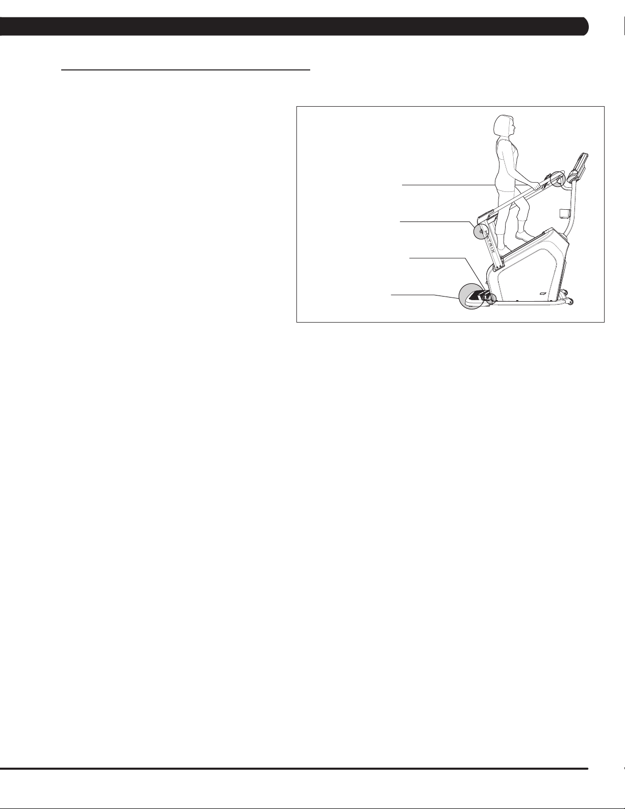
MOUNTING THE CLIMBMILL
1. There are two EMERGENCY STOP BUTTONS on the
ClimbMill. One emergency stop button is located at the top of
the handlebars and the second is located on the lower right
side handlebar. The EMERGENCY STOP BUTTONS will
bring the step surfaces to a complete stop when pressed.
2. The CONTROL ZONE will bring the step surfaces to
a complete stop upon detecting an object. The AUTO-
STOP SENSOR will bring the step surfaces to a complete
stop upon detecting an object under the bottom step.
3. Stand directly behind the ClimbMill on the CONTROL
ZONE. Grasp the handlebars and step onto the ClimbMill
until you are within comfortable reach of the console, top
emergency stop lever, and in-reach handlebar controls.
4. To determine proper workout position, stand on the
steps within comfortable reach of the console. Maintain a
constant distance from the console and in-reach handlebar
controls. Keep your knees slightly bent at all times.
5. Dismounting the ClimbMill - After the steps have
come to a complete stop and while grasping the
handlebars, step down onto the CONTROL ZONE.
Emergency stop
Emergency stop
AUTO-STOP SENSOR
CONTROL ZONE
POWER
The power cord must be plugged into the power socket, which is
located in the front of the equipment on the front of the machine.
The power switch is located next to the power socket. Make
sure it is in the on position. Unplug cord when not in use.
WARNING!
Never operate product if it has a damaged cord or plug, if it
is not working properly, if it has been damaged, or immersed
in water. Please reference contact information on the back
cover of the INFORMATION CARD for assistance.
3
Page 6
CHAPTER 2: IMPORTANT SAFETY INFORMATION
2.2 ELECTRICAL REQUIREMENTS
GROUNDING INSTRUCTIONS
This product must be grounded. If the equipment should malfunction or breakdown, grounding provides a path of least resistance for electrical
current to reduce the risk of electrical shock. This product is equipped with a cord having an equipment-grounding conductor and a grounding
plug. The plug must be plugged into an appropriate outlet that is properly installed and grounded in accordance with local codes and ordinances.
GROUNDED POWER CORD
3-POLE GROUNDED OUTLET
DANGER
Improper connection of the equipment-grounding conductor can result in a risk of electric shock. Check with a qualified
electrician or serviceman if you are in doubt as to whether the product is properly grounded. Do not modify the plug
provided with the product. If it will not fit the outlet, have a proper outlet installed by a qualified electrician.
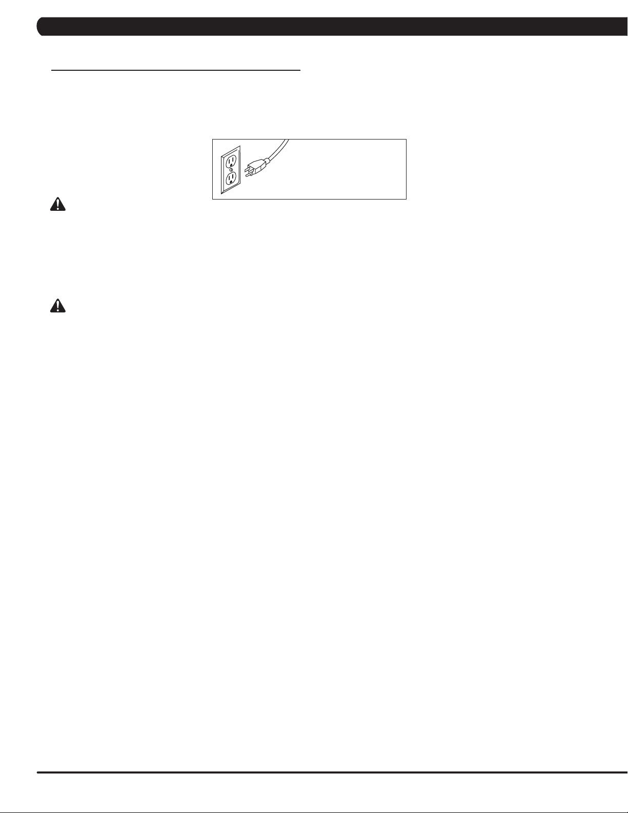
This product is for use on a nominal 110-120 Volt circuit and has a grounding plug that looks like the plug in the illustration. Make sure
that the product is connected to an outlet having the same configuration as the plug. No adapter should be used with this product.
WARNING
Connect this exercise product to a properly grounded outlet only.
Never operate product with a damaged cord or plug even if it is working properly. Never operate any product if it appears
damaged, or has been immersed in water. Contact Customer Tech Support for replacement or repair.
It is essential that this equipment is used only indoors, in a climate controlled room. If the equipment has been exposed to colder temperatures or
high moisture climates, it is strongly recommended that the equipment is warmed up to room temperature before first time use. Failure to do so
may cause premature electronic failure.
4
Page 7
CHAPTER 2: IMPORTANT SAFETY INSTRUCTIONS
2.3 LOCATING THE UNIT
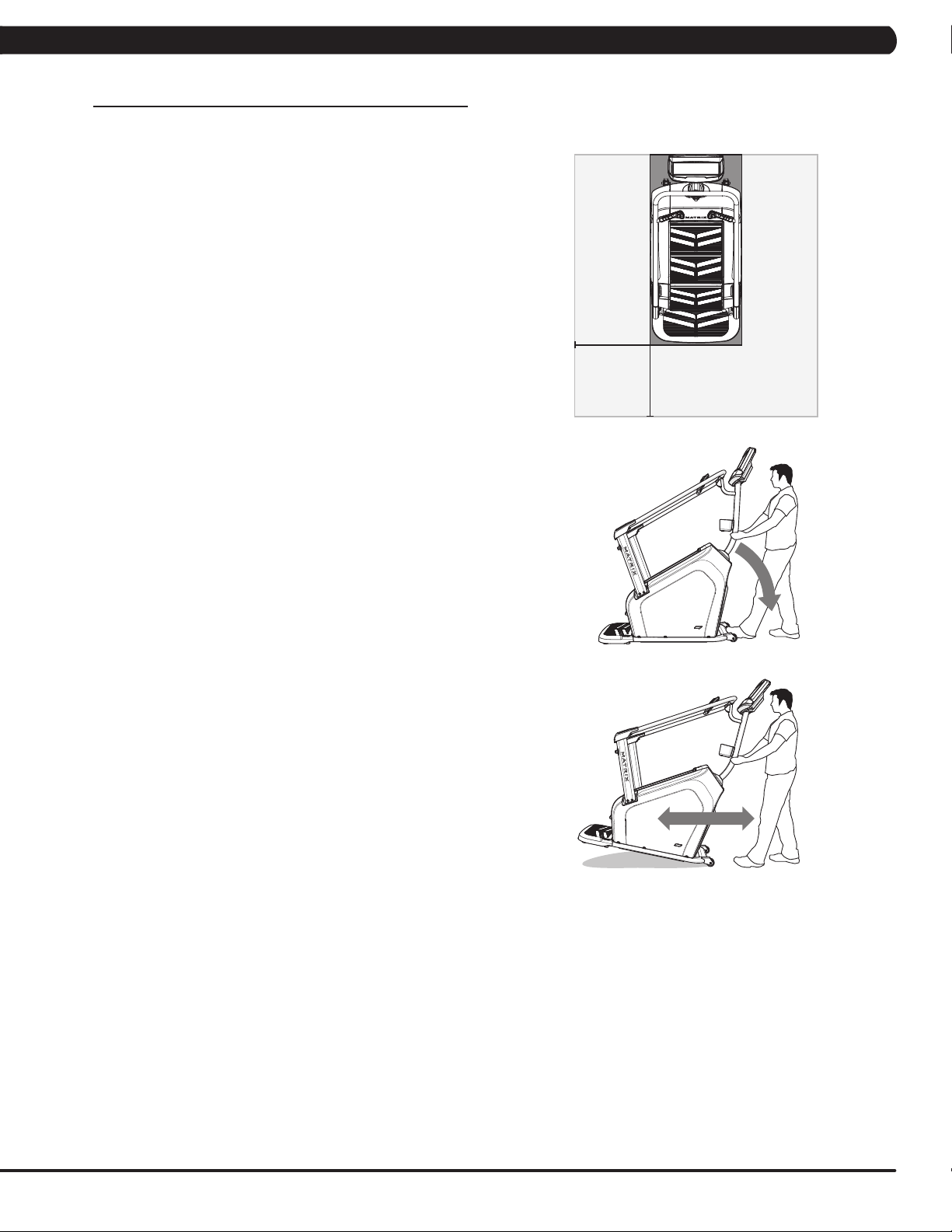
LOCATION OF THE UNIT
Place the ClimbMill on a level surface. For ease of access,
there should be an accessible space preferentially on both
sides and the rear of the ClimbMill that is at least 0.6 meters
(24 inches). Do not place the ClimbMill in any area that will
block any vent or air openings. The ClimbMill should not be
located in a garage, covered patio, near water or outdoors.
HEIGHT AND WEIGHT REQUIREMENTS
The equipment adds 20” – 25” (50 – 64.5 cm) to a user’s height.
For example, a 6’1” (185 cm) tall user will be 7’9” – 8’2” (236 – 249
cm) off the floor. The C50 requires a minimum user weight of 99 lbs
(45 kgs) and has a maximum user capacity of 300 lbs (136 kgs).
FOOTPRINT: 135 x 72 cm / 53” x 28”
HEIGHT: 190 cm / 75”
WEIGHT: 138.5 kg / 293 lbs.
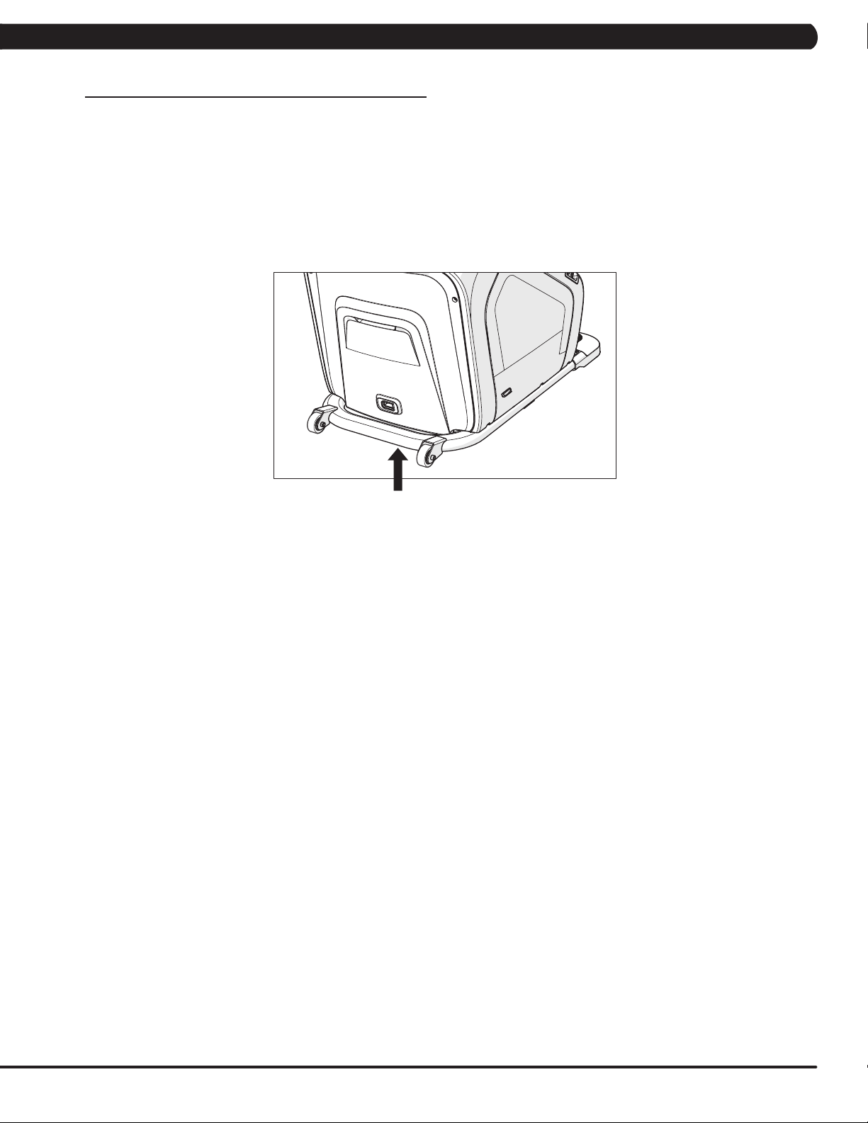
MOVING THE UNIT
The ClimbMill has a pair of transport wheels built into the
front of the frame. To move, first remove the power supply
and firmly grasp the console mast, carefully tilt (1) and roll (2).
Note: be sure to grab the steel bar and not the console.
FREE AREA
0.6 M (2 FT)
5
Page 8
CHAPTER 2: IMPORTANT SAFETY INSTRUCTIONS
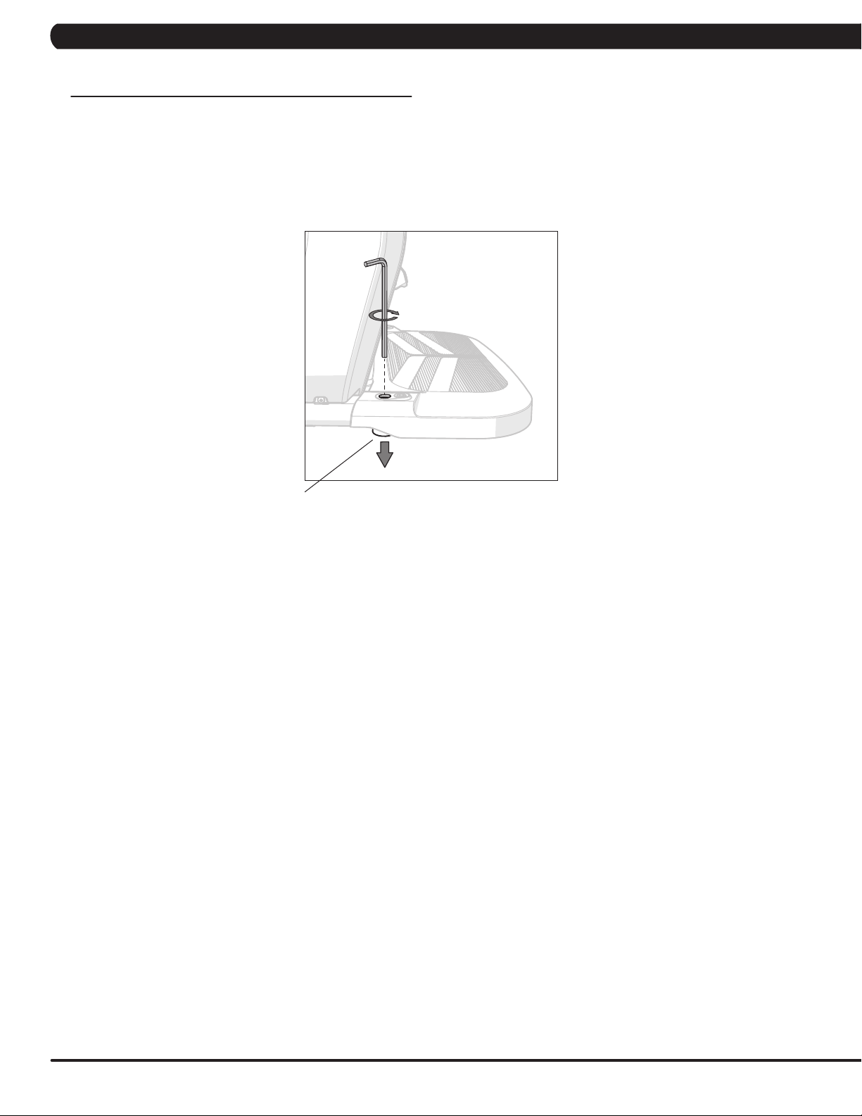
2.4 STABILIZING THE CLIMB MILL
LEVELING THE EQUIPMENT
Locate a level, stable surface to position the equipment. The equipment has levelers located below the Control Zone
step. Raise or lower one or both of the adjustable levelers using a 6mm allen wrench through the access hole.
A carpenter’s level is recommended.
NOTE: There are only two levelers on the equipment.
LEVELER
6
Page 9
CHAPTER 3: PREVENTIVE MAINTENANCE
3.1 CARE AND MAINTENANCE INSTRUCTION
MAINTENANCE SCHEDULE
ACTION FREQUENCY
Clean and inspect the ClimbMill:
• Turn off the machine with the ON/OFF switch, then unplug the power cord at the wall outlet.
• Clean entire machine using water and a mild soap applied to a soft cloth. Never use solvents, as they can
cause damage to the ClimbMill. Never spray cleaner directly onto the machine or console.
• Inspect the power cord. If the power cord is damaged, please reference contact information on the back
cover of the INFORMATION CARD for assistance.
• Make sure the power cord is not underneath the machine or in any other area where it can become pinched
or cut during storage or use.
• If any labels are damaged or illegible, please reference contact information on the INFORMATION CARD for
replacement.
Clean underneath the machine:
• Turn off the machine with the ON/OFF switch, then
• unplug the power cord at the wall outlet.
• Remove the debris tray from under the machine by sliding it out from the right side and wipe or vacuum any
grease, dust particles or other objects that may have accumulated on it. Return the debris tray to its previous
position.
• Wipe or vacuum any dust particles or other objects that may have accumulated around the machine.
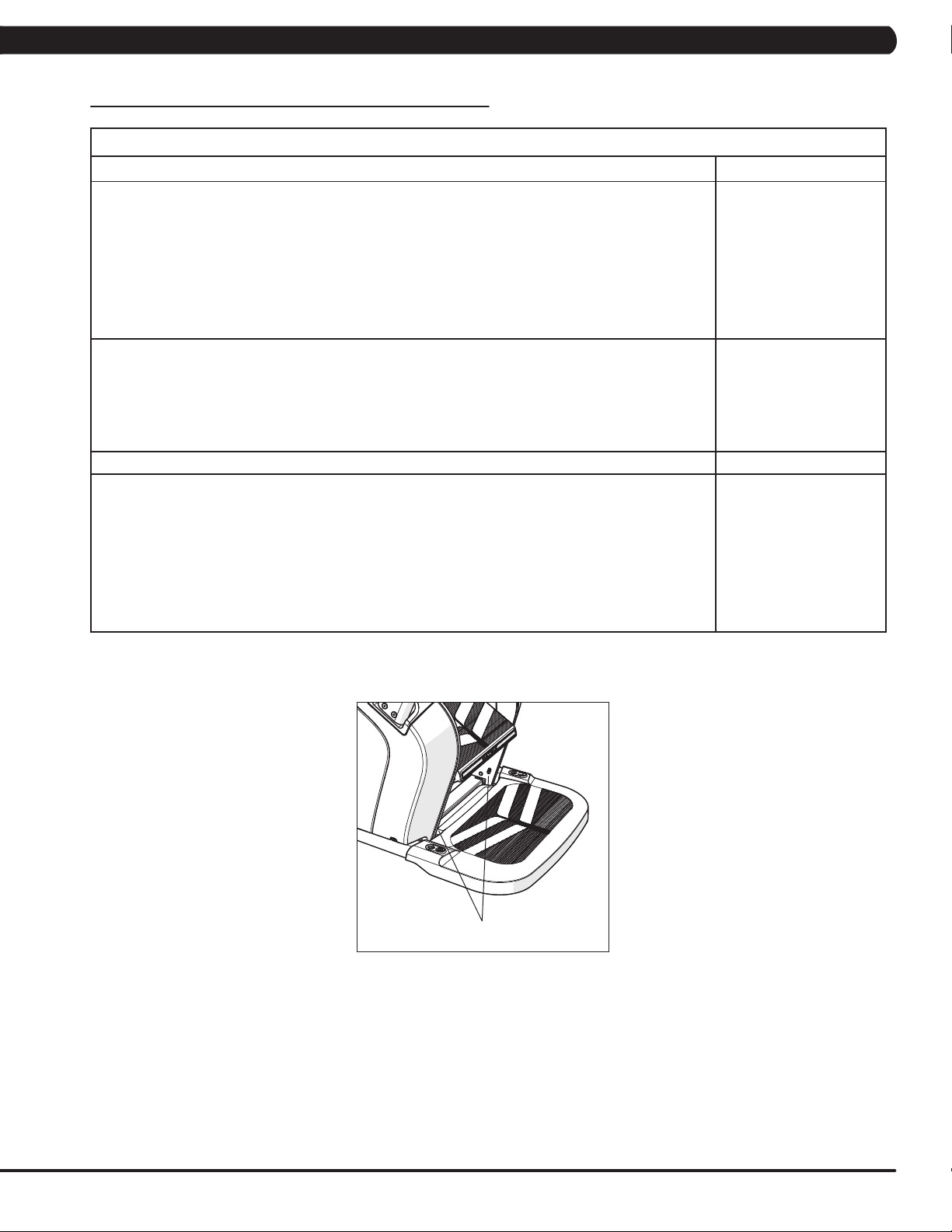
Unplug the ClimbMill and clean the AUTO STOP SENSORS (located under the bottom step). WEEKLY
IMPORTANT!
• Turn off the machine with the ON/OFF switch, then unplug the power cord at the wall outlet. Wait 60
seconds.
• Inspect all assembly bolts of the machine for proper tightness. Reference assembly steps for proper tension
of each bolt.
• Remove the front access cover. Wait until ALL LED lights turn off.
• Clean the motor and lower board area to eliminate any lint or dust particles that may have accumulated.
Failure to do so may result in premature failure of key electrical components.
• Check step motion by rotating the steps backwards to ensure free movement.
• Check stability to ensure the ClimbMill does not rock or wobble. Adjust levelers as necessary.
BEFORE EACH USE
WEEKLY
MONTHLY
AUTO STOP SENSORS
7
Page 10

4.1 ELECTRICAL DIAGRAMS
SYSTEM BLOCK
CHAPTER 4: TROUBLESHOOTING
8
Page 11
CHAPTER 4: TROUBLESHOOTING
4.1 ELECTRICAL DIAGRAMS - CONTINUED
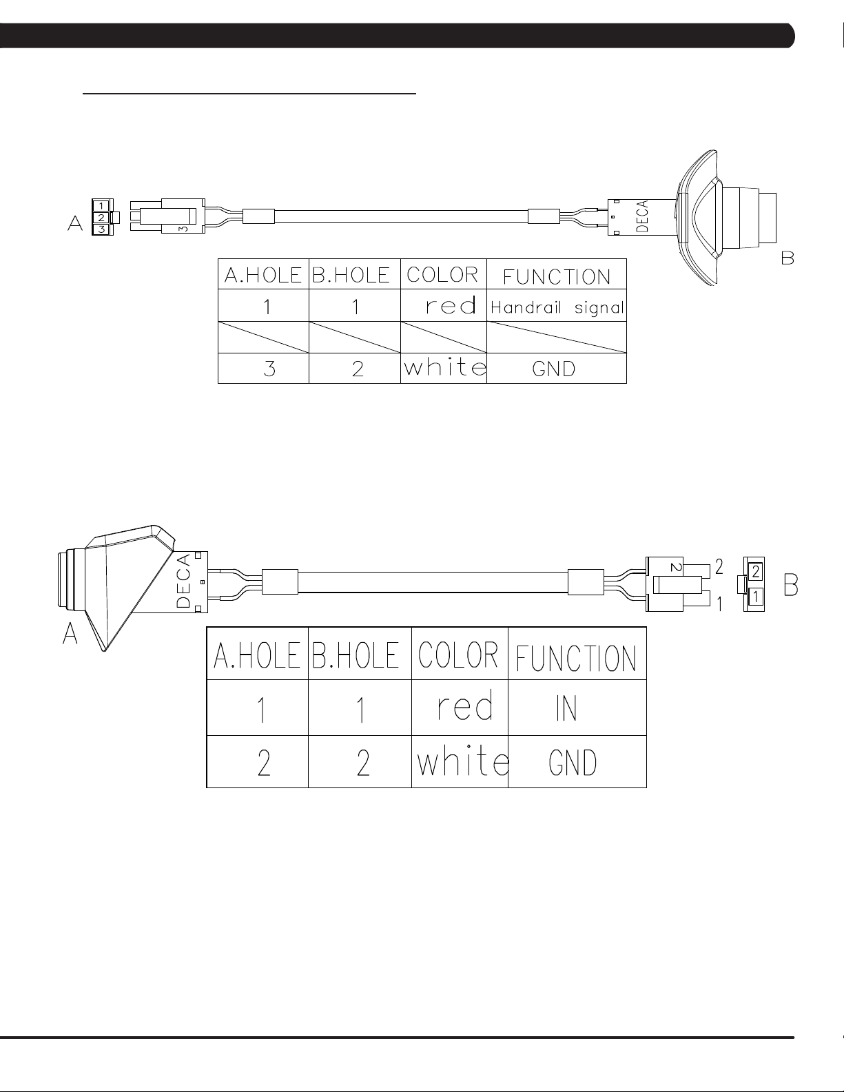
AG12- SAFE SWITCH SET (HANDLEBAR)
AC15 - SAFE SWITCH SET (CONSOLE MAST)
9
Page 12
CHAPTER 4: TROUBLESHOOTING
A
B
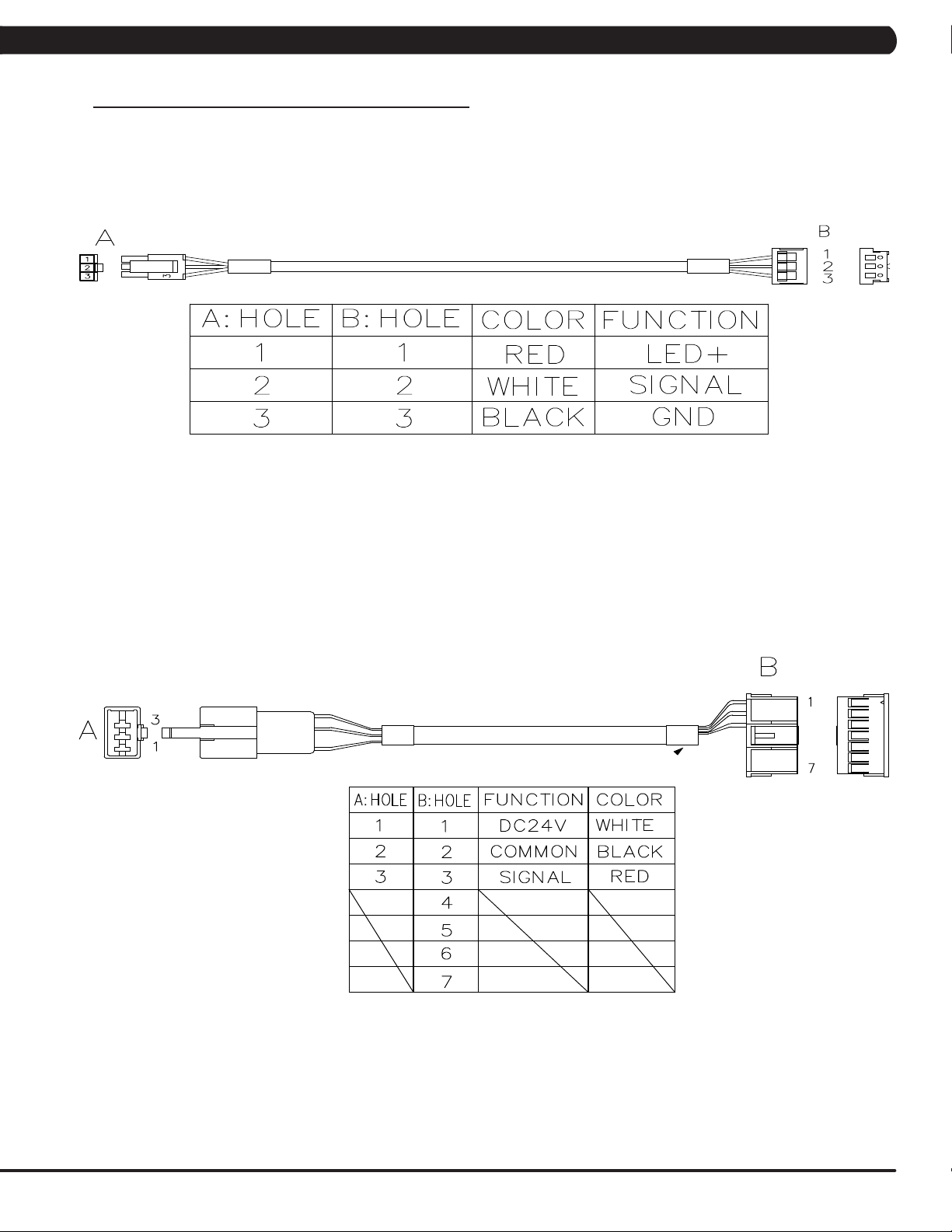
4.1 ELECTRICAL DIAGRAMS - CONTINUED
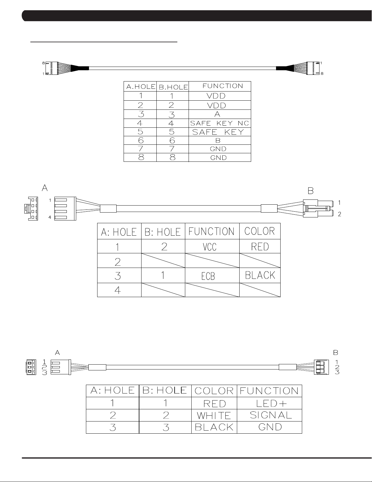
P01 - DIGITAL COMMUNICATION WIRE
P16 - ECB LOAD WIRE
P17- SPEED FEEDBACK EXTENSION WIRE
10
Page 13
CHAPTER 4: TROUBLESHOOTING
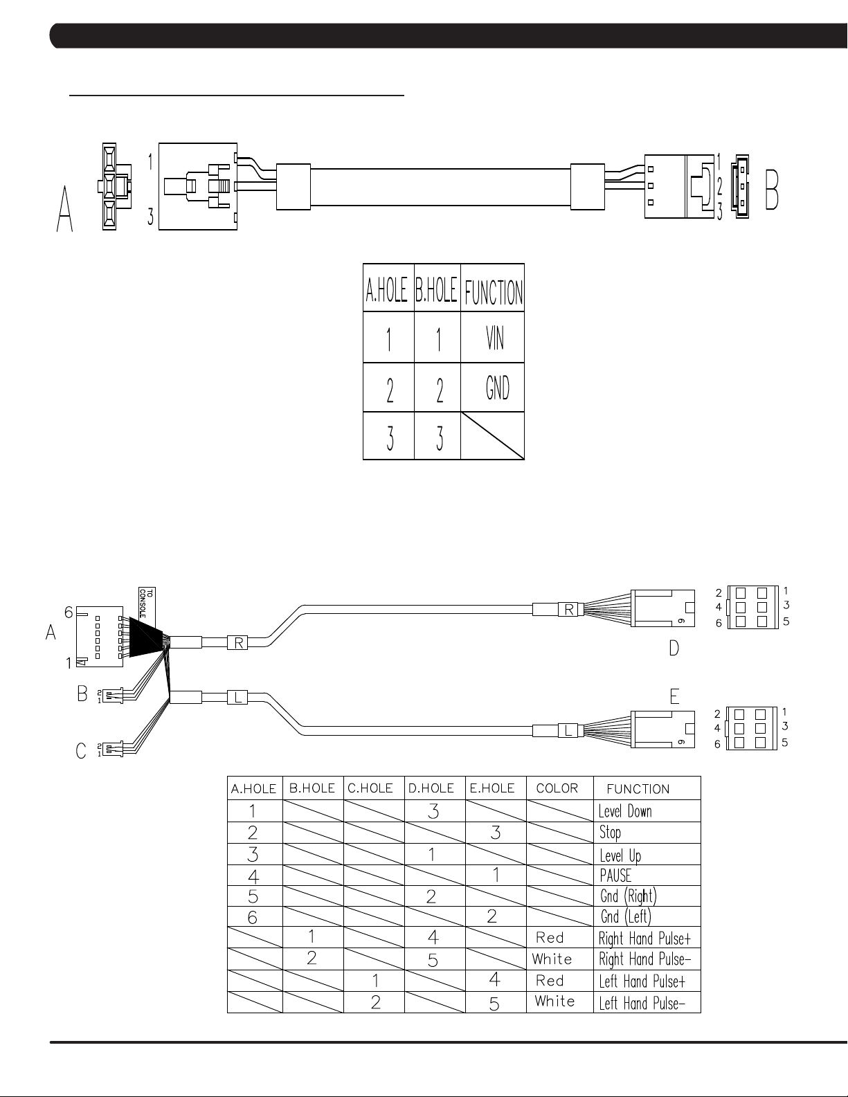
4.1 ELECTRICAL DIAGRAMS - CONTINUED
P18 - SPEED FEEDBACK EXTENSION WIRE (PULLEY)
P19 - POWER EXTENSION WIRE
11
Page 14
CHAPTER 4: TROUBLESHOOTING
4.1 ELECTRICAL DIAGRAMS - CONTINUED
P21 - SENSOR EXTENSION WIRE
P27 - PULSE CONNECT WIRE
12
Page 15
CHAPTER 4: TROUBLESHOOTING
4.1 ELECTRICAL DIAGRAMS - CONTINUED
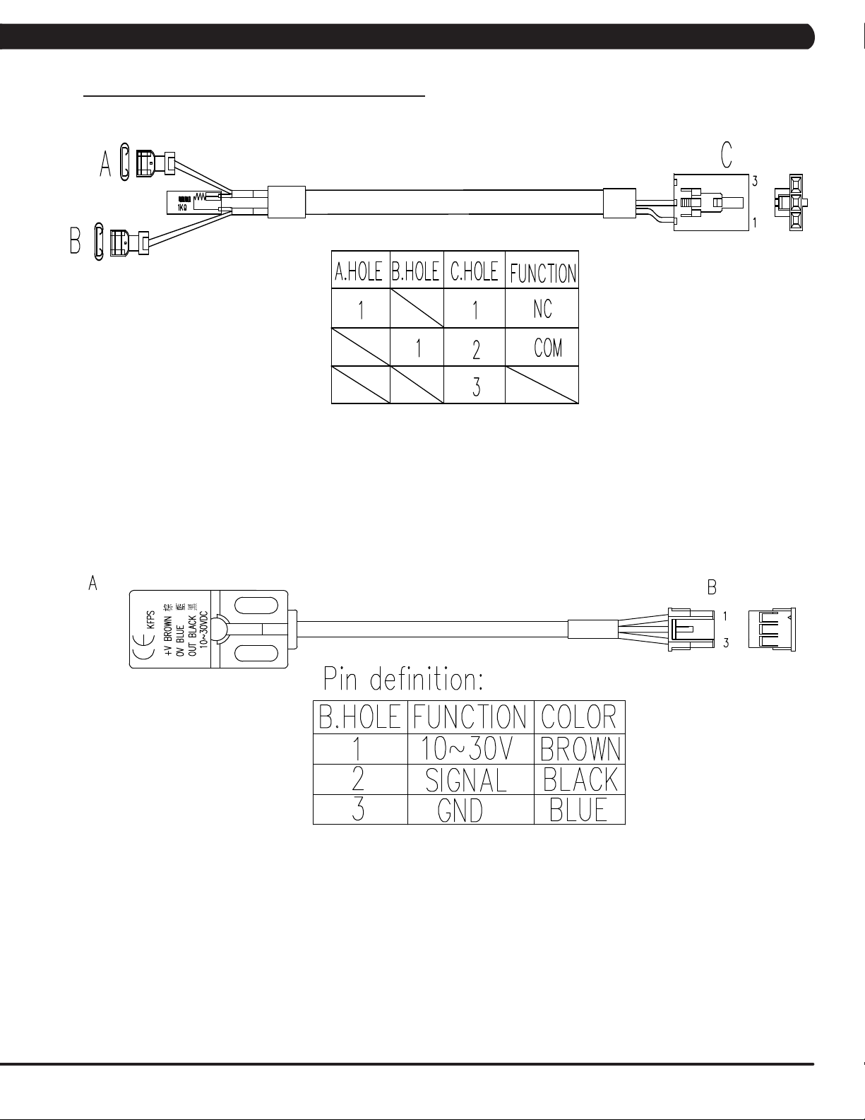
P28 - LIMIT SWITCH WIRE; A
P69 - PROXIMITY SENSOR CONNECT WIRE
13
Page 16
CHAPTER 4: TROUBLESHOOTING
4.1 ELECTRICAL DIAGRAMS - CONTINUED
G39 - H/P SENSOR WIRE (L)
G40 - H/P SENSOR WIRE (R)
14
Page 17

CHAPTER 4: TROUBLESHOOTING
4.1 ELECTRICAL DIAGRAMS - CONTINUED
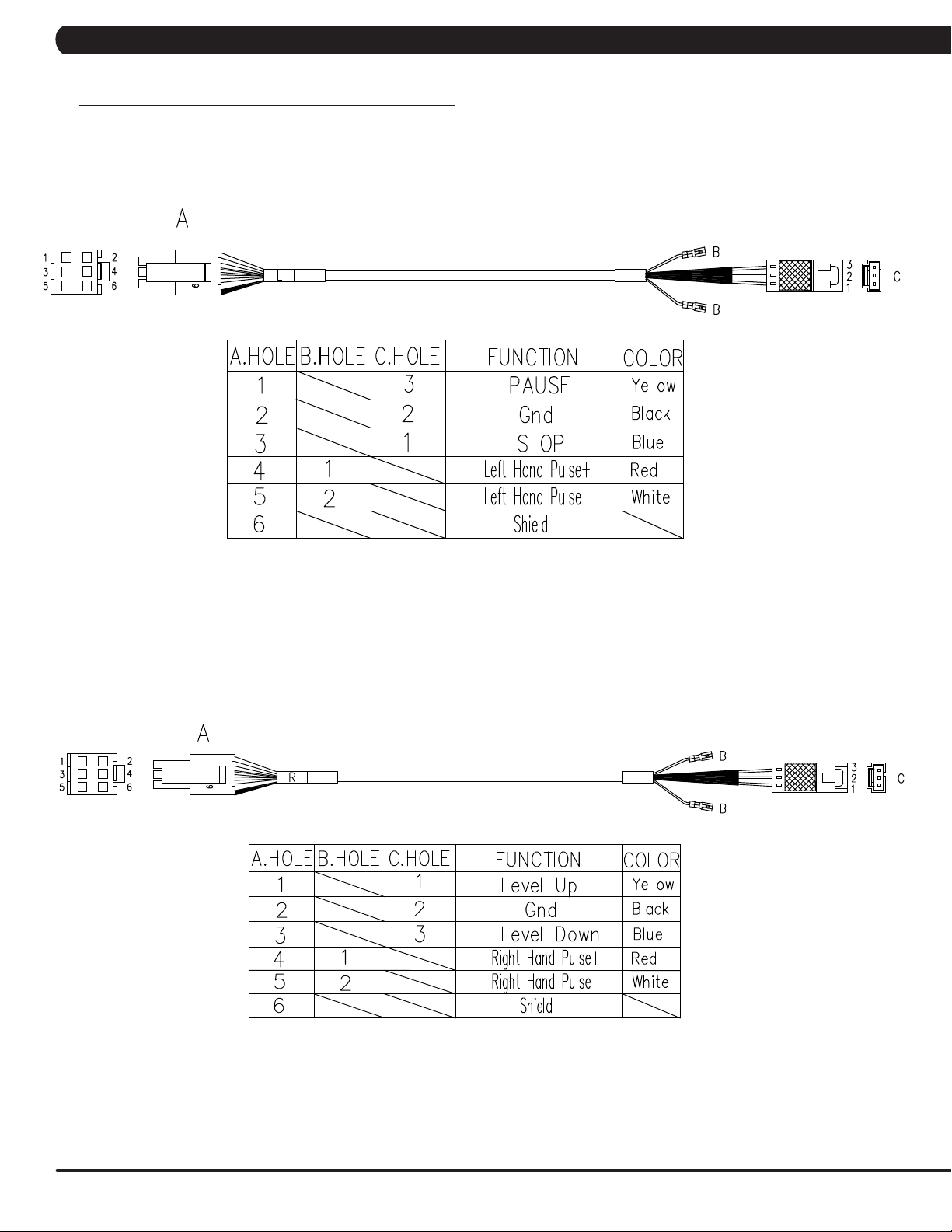
P51 - SENSOR WIRE SET
P68 - SAFE SWITCH EXTENSION WIRE
15
Page 18

4.2 LCB LED INDICATORS
Console
RPM
Pressure Sensor
Brake
ECB 1/
E_STOP
LED19
LED20
LED15
LED13
Frame IR
(Receiver)
Frame IR
LED12
LED8
LED10
LED5
LED7
LED 21
LED1/
LED4
CHAPTER 4: TROUBLESHOOTING
ECB 2
(Transmitter)
LED2/
LED3/
RPM1
LED18
Proximity Sensor
(Control zone)
16
Page 19

CHAPTER 4: TROUBLESHOOTING
4.2 LCB LED INDICATORS - CONTINUED
---------------------------------------------------------------------------------Firmware definition-----------------------------------------------------------------------------------
LED DESCRIPTION DESCRIPTION STATUS
LED1 LCB software working status Flashing - Working
OFF - Default
LED2 LCB Error status Light - LCB with error
Off - LCB without error
LED3 Safety Key action status Light - Active
Off - No active
LED4 UCB and LCB communication status Flashing - Active
Off - Abnormal
--------------------------------------------------------------------------------Hardware definition-----------------------------------------------------------------------------------
LED DESCRIPTION DESCRIPTION STATUS
LED5 DC 24V lamp Indicates if the voltage supply is present
Light - Working
Off - Not working
LED7 DC 3.3V lamp Indicates if the voltage supply is present
Light - Working
Off - Not working
LED8 Electro-magnet device 2 PWM lamp Indicates if the ECB PWM signal supply is present
Light - Working
Off - Not working
LED10 Electro-magnet device 1 PWM lamp Indicates if the ECB PWM signal supply is present
Light - Working
Off - Not working
LED12 DC brake release lamp (manual switch) Light - The brake is on release position
Off - The brake is on lock position
LED13 DC 12V lamp Indicates if the voltage supply is present
Light - Working
Off - Not working
LED15 Frame IR transmitter power lamp Indicates if the Frame IR transmitter power supply is present
Light - Working
Off - Not working
LED18 Proximity sensor signal lamp Flashing - Signal detected from proximity sensor
LED19 RPM signal lamp Flashing - Detecting RPM from speed sensor
LED20 E-STOP signal lamp
(only E-STOP of console mast/arm rest set)
LED21 RPM1 signal lamp Flashing - Detecting RPM from the second speed sensor
Light - E-Stop active
Off - E-Stop not active
17
Page 20

CHAPTER 4: TROUBLESHOOTING
4.3 ERROR CODE LIST
01XX: Motor Errors
CODE CLASS DESCRIPTION MACHINE SOLUTION
a. On standby mode, measure the resistance on ECB1. Please check the ECB extension
cable connection
at the LCB (pins 1 & 3 for ECB1, there should be between 10.13 ~ 10.27 ohms.
- If the ECB resistance is out of the range, replace the ECB.
- If the ECB resistance is within the range, replace the LCB.
b. Check the gap of ECB1. There should be a gap of .5mm between the ECB and the
flywheel.
a. Check the connection of the ECB extension cable from the LCB to the ECB.
b. On the workout, check to see if LED10 on the LCB have a brief light.
- If LED10 do not have a brief light, replace the LCB.
- If LED10 do have a brief light, check the ECB extension cable connection at the LCB
(pins 1 & 3
for ECB1), there should be between 10.13 ~ 10.27 ohms.
- If the ECB resistance is out of the range, replace the ECB.
- If the ECB resistance is within the range, replace the LCB.
01AC C
01AF C
Electro magnet
(ECB) over current.
Electro magnet
(ECB) disconnected.
C
C
02XX: LCB Errors
CODE CLASS DESCRIPTION MACHINE SOLUTION
02AB C
02A0 C Encoder error C
02B2 C
02B4 C
02BF C
02C0 C
Machine type
error.
Safe key action
response
Resistance
Type Error.
DC brake Over
Current
DC brake in
manual mode.
C Change the machine type on the console to match the correct frame.
a. Check the connection of the speed sensor cable from the LCB to the speed sensor.
b. Check to see if LED19 on the LCB is on when the brake is turned to the left release
position.
c. If it is off, move the stairs about 3 stairs and check to see if LED19 is flashing.
- If not, replace the first speed sensor (near the brake).
- If yes, adjust the first speed sensor position and clean the speed sensor of any
debris then re-test.
C
C
C
C
a. Check the connection of the safety key (emergency stop) switch. If the switch is
always open or shorted out, replace the switch.
b. If the emergency stop does not resolve the issue, replace the UCB.
a. Make sure machine type is set for the correct frame in console.
- If yes, replace LCB.
- If no, change to correct type and reboot the power.
a. Check the power extend wire connection between the brake and LCB for any damage.
b. Check to see if the stairs will move when you are in the stop position. If yes, replace
the brake.
a. Check if the DC brake is in the right, lock position. Turn the brake (move to the right) if
in release position.
b. Replace the brake.
18
02C1 C
Speed tracking
error
a. Adjust the speed sensor position and clean the speed sensor of any debris.
C
b. Check the ECB extension cable connection at the LCB (pins 1 & 3 for ECB1), there
should be between 9.5 ~ 10.9 ohms, check which ECB is outside the range and replace
it.
Page 21

CHAPTER 4: TROUBLESHOOTING
4.3 ERROR CODE LIST - CONTINUED
02XX: LCB Errors - continued
CODE CLASS DESCRIPTION MACHINE SOLUTION
02C5 C
02C6 C
02C7 C
02CD C DC brake disconnects C
024B B
0250 B
The frequency error
from frame IR sensor.
The receiver disconnected from control
zone.
The receiver disconnected from frame IR
sensor
Position sensor is no
response
The 2nd speed sensor
(near the sproket set)
is no response.
C Replace LCB set.
C
C
C
C
a. Check the connection of the control zone extension cable from the LCB to
the control zone.
b. Replace the control zone.
a. Check the connection of the frame IR receiver cable from the LCB to the
frame IR receiver sensor.
b. Replace the frame IR receiver cable.
a. Check the power extend wire connection between the brake and LCB for
any damage.
b. Check to see if the LED16 on the LCB is on when the unit is power on.
- If not, replace the LCB.
- If yes, eplace the brake.
a. Check the connection of the position sensor cable from the LCB to the posi-
tion sensor.
b. Turn off the DC brake by moving the red handle downward. Rotate the stairs
a least 1 complete revolution. Confirm the gap is lower than 3.5mm between
the axle and proximity sensor and does not hit.
c. Check to see if LED D8 on the LCB is flashing when press "Go" and rotate
the stairs.
- If not, treplace the proximity sensor.
- If yes, replace the LCB.
a. Check the speed extend wire connection between the brake and LCB for
any damage.
b. Check to see if the LED21 on the LCB is flashing when the unit is workout.
- If not, replace the second speed sensor (near the sproket set).
- If yes, adjust the second speed sensor position and clean the speed sensor of any debris then re-test or replace LCB.
04XX: Communication Errors
CODE CLASS DESCRIPTION MACHINE SOLUTION
04A0 C
0441 B
LCB does not have
communication
response from UCB
When UCB implements a command,
but the LCB/MCB
cannot execute the
command
Communication
Errors
Communication
Errors
a. Check the connection of the console cable at both ends and perform continuity test.
b. Replace LCB.
Enter the Engineer mode disable B Level Error, bypass CLASS A and B error
code.
19
Page 22

CHAPTER 5: PART REPLACEMENT GUIDE
5.1 SERVICE COVER REPLACEMENT
1) Turn off power and disconnect the cord from the machine.
2) Remove the 2 screws holding the service cover to the side cover (Figure A).
3) Pull up on the service cover to remove it (Figure B & C).
FIGURE A FIGURE B
20
FIGURE C
Page 23

CHAPTER 5: PART REPLACEMENT GUIDE
5.2 SIDE COVER REPLACEMENT
1) Turn off power and disconnect the cord from the machine.
2) Remove the service covers as outlined in Section 5.1.
3) Remove the 3 screws holding the side cover to the frame (Figures A).
4) Use the flat-head screwdriver to separate the snap-fit of the handlebar cover (Figures B & C).
FIGURE A FIGURE B
5) Slide up the handlebar cover to halfway of the handlebar mast.
6) Remove the 2 screws holding the side cover to the frame (Figures D).
7) Pull up on the side cover to remove it (Figures E).
8) Reverse Steps 1-7 to install a new side cover.
FIGURE DFIGURE C
FIGURE E
21
Page 24

CHAPTER 5: PART REPLACEMENT GUIDE
5.3 CONSOLE REPLACEMENT
1) Turn off power and disconnect the cord from the machine.
2) Remove the 4 screws holding the console back cover to the console (Figure A).
3) Remove the 4 screws holding the console to the console mast (Figure B).
FIGURE BFIGURE A
4) Disconnect the console cable and other wiring (hand pulse and quick key cables) from the console, then remove the console (Figure C).
FIGURE C
5) Reverse Steps 1-4 to install a new console set. NOTE: Tighten the bolts removed in Step 3 to 9.5 N-m.
6) Test the Climb Mill for function as outlined in Section 5.19.
22
Page 25

CHAPTER 5: PART REPLACEMENT GUIDE
5.4 FRONT SHROUD REPLACEMENT
1) Turn off power and disconnect the cord from the machine.
2) Remove the service cover as outlined in Section 5.1.
3) Remove the side covers as outlined in Section 5.2.
4) Remove the console as outlined in Section 5.3.
5) Remove the 4 screws holding the front cover to frame (Figure A & B).
FIGURE A
6) Remove the 2 screws holding the handlebar to the console mast (Figure C).
7) Disconnect the E-stop wire connector at the bottom of the console mast (Figure D).
FIGURE C
FIGURE B
FIGURE D
23
Page 26

CHAPTER 5: PART REPLACEMENT GUIDE
5.4 FRONT SHROUD REPLACEMENT - CONTINUED
8) Remove the console mast cover (Figure E).
9) Remove the 5 screws holding the console mast to the frame (Figure F).
FIGURE E FIGURE F
10) Pull the console cable out of the console mast (Figure G).
11) Pull up the front shroud and remove it from frame (Figure H).
FIGURE G
12) Reverse Steps 1-11 to install a new front shroud.
13) Test the Climb Mill for function as outlined in Section 5.19.
FIGURE H
24
Page 27

CHAPTER 5: PART REPLACEMENT GUIDE
5.5 LOWER CONTROL BOARD (LCB) REPLACEMENT
1) Turn off power and disconnect the cord from the machine.
2) Remove the service covers as outlined in Section 5.1.
3) Remove the 2 screws holding the LCB cover to the frame (Figure A).
4) Disconnect all wiring from the LCB, and cut any wire ties holding the cable to the LCB (Figure B).
FIGURE A
5) Remove the 2 screws holding the LCB to the frame (Figure C).
6) Remove the LCB set from the unit (Figure D).
FIGURE B
FIGURE DFIGURE C
7) Reverse Steps 1-6 to install a new LCB.
8) Test the Climb Mill for function as outlined in Section 5.19.
25
Page 28

CHAPTER 5: PART REPLACEMENT GUIDE
5.6 HANDLEBAR SET REPLACEMENT
1) Turn off power and disconnect the cord from the machine.
2) Remove the screw connect the handlebar to the cover on right / left side (Figure A).
3) Remove the screw holding the the handlebar to the right / left of handlebar mast (Figure B).
FIGURE A FIGURE B
4) Remove the 2 screws holding the handlebar to the console mast (Figure C). .
5) Disconnect the wires that connects the left/right hand grip cable to the hand pulse extension wire (Figure D ).
FIGURE C
6) Remove the handlebar set and remove the hand grip as outlined in Section 5.8. NOTE: Tighten all bolts from steps 2–4 to 24 Nm. The
left and right locations of hand grip set are different between retail climbMill (CS31) and commercial climbMill (CS29/30).
7) Reverse Steps 1-6 to install a new handlebar set.
8) Test the Climb Mill for function as outlined in Section 5.19.
FIGURE D
26
Page 29

CHAPTER 5: PART REPLACEMENT GUIDE
5.7 EMERGENCY STOP SET REPLACEMENT
A. Emergency Stop Set (on the console mast)
1) Turn off power and disconnect the cord from the machine.
2) Remove the service cover as outlined in Section 5.1.
3) Disconnect the E-stop wire connector at the bottom of the console mast (Figure A).
4) Remove the screw holding the E-stop set to the console mast (Figure B).
FIGURE A
5) Pull the E-stop set out of the console mast (Figure C).
6) Reverse Steps 1-5 to install a new E-stop set.
7) Test the Climb Mill for function as outlined in Section 5.19.
FIGURE B
FIGURE C
27
Page 30

CHAPTER 5: PART REPLACEMENT GUIDE
5.7 EMERGENCY STOP SET REPLACEMENT - CONTINUED
B. Emergency Stop Set (on the lower right side handlebar)
1) Turn off power and disconnect the cord from the machine.
2) Remove the 2 screws holding the E-stop set to the lower right side handlebar (Figure A).
3) Pull the E-stop cable connector out of the handlebar mast and disconnect it (Figure B).
FIGURE A FIGURE B
4) Remove the E-stop set (Figure C).
FIGURE C
28
5) Reverse Steps 1-4 to install a new E-stop set.
6) Test the Climb Mill for function as outlined in Section 5.19.
Page 31

CHAPTER 5: PART REPLACEMENT GUIDE
5.8 HANDGRIP SERVICE
1) Turn off the power and disconnect the cord from the machine.
2) All items on the handlebar are removed using a Phillips screwdriver from the underside of the bar.
3) Once the screws are removed, lift the part carefully then disconnect any wire connections to fully remove the part. This includes the handgrip
cover (Figures A & B).
FIGURE A FIGURE B
4) Remove the handgrip from handlebar (Figure C).
FIGURE C
5) Reverse Steps 1-4 to install a new handgrip. NOTE: Before assembling the quick key cover, push the grip cable back to handgrip rst
(Figure D) to prevent cable injury.
6) Test the Climb Mill for function as outlined in Section 5.19.
29
Page 32

CHAPTER 5: PART REPLACEMENT GUIDE
5.9 STAIR REPLACEMENT
1) Turn off power and disconnect the cord from the machine.
2) Remove the service cover as outlined in Section 5.1.
3) Remove the side covers as outlined in Section 5.2.
4) Remove the front shroud as outlined in Section 5.4.
5) Turn the brake bar to the right to lock the stairs in place (Figure A).
6) Remove the X shaped clip from the long axle on the upper side of the stair needing to be replaced (Figure B).
FIGURE A FIGURE B
6) Pull out the axle from the opposite side where you removed the X shaped clip (Figure C). NOTE: 1. Pay attention to the order of the parts
sequence on the axle as you remove it (Figure D). The correct parts sequence is X shaped clip > bearing > washer > chain > spacer >
stair. 2. Do not reuse the X-washer retainers. Order replacements with your stair or bearing order.
FIGURE C
FIGURE D
30
Page 33

CHAPTER 5: PART REPLACEMENT GUIDE
5.9 STAIR REPLACEMENT - CONTINUED
7) Remove the axle from the lower side of the stairs needing to be replaced following the same procedure as Steps 4-6.
8) Remove the stair set when you have removed both axles (Figure E).
9) Remove the E-shaped clip from the short axle between the 2 portions of the stair set (Figure F). This will allow you to separate the 2 portions
of the stair set.
FIGURE FFIGURE E
10) Reverse Steps 1-9 to install a new stair set.
11)Turnthebrakebartothelefttounlockthestairsoncethereplacementisnished.
12) Test the Climb Mill for function as outlined in Section 5.19.
31
Page 34

CHAPTER 5: PART REPLACEMENT GUIDE
5.10 DRIVE BELT REPLACEMENT
1) Turn off power and disconnect the cord from the machine.
2) Remove the service cover as outlined in Section 5.1.
3) Remove the side covers as outlined in Section 5.2.
4) Loosen the belt tension bolt and rotate the idler set counter-clockwise until there is enough slack in the belt to remove it (Figures A ~ D).
FIGURE BFIGURE A
32
FIGURE DFIGURE C
5) Install the replacement belt and reverse necessary steps to secure the assembly until the belt is tight. NOTE: Tighten the drive belt to 120 ~
130 lbs (90 ~ 105 Hz). The idler bolt should be torqued to 80 N-m.
6) Test the Climb Mill for function as outlined in Section 5.19.
Page 35

CHAPTER 5: PART REPLACEMENT GUIDE
5.11 DRIVE SET REPLACEMENT
NOTE: BEFORE REMOVING THE BRAKE SET, BLOCK THE STAIRS FROM ROTATING (PLACE A BLOCK UNDER THE BOTTOM STAIR)
TO PREVENT INJURY.
1) Turn off power and disconnect the cord from the machine.
2) Remove the service cover and side cover as outlined in Section 5.1 & 5.2.
3) Turn the brake lever to the right to lock the stairs (Figure A) to prevent movement that could cause injury.
4) Disconnect the speed sensor wire, a ECB wire, and a brake wire. (Figure B).
FIGURE A
5) Remove the 3 screws that connect the top cover to the drive set and remove it (Figure C & D).
FIGURE B
FIGURE DFIGURE C
6) Loosen the belt tension bolt on the left side of the tension pulley and rotate the pulley counter-clockwise until there is enough slack in the
belt to remove it (Figures E & F).
FIGURE FFIGURE E
33
Page 36

CHAPTER 5: PART REPLACEMENT GUIDE
5.11 DRIVE SET REPLACEMENT - CONTINUED
7) Remove the 2 screws on each side holding the drive set to the frame (Figure G & H).
FIGURE G FIGURE H
8) Remove the 1 screws holding the drive set to the frame (Figure I).
9) Remove the drive set from the frame (Figure J).
FIGURE I FIGURE J
10) Reverse Steps 1-9 to install a new drive set. NOTE: Torque the bolt removed in Step 8 to 80 N-m. Tighten the bolts removed in Step 7 to
40 N-m. Tighten the drive belt to 120 ~ 130 lbs (90 ~ 105 Hz) for a new belt. Tighten the bolts removed in Step 6 to 80 N-m.
11) Test the Climb Mill for function as outlined in Section 5.19.
34
Page 37
CHAPTER 5: PART REPLACEMENT GUIDE
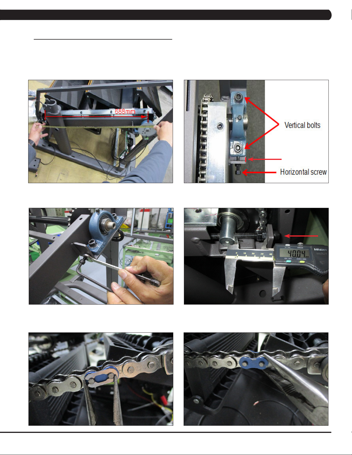
5.12 CHAIN REPLACEMENT
1) Turn off the power and disconnect the cord from the machine.
2) Remove the service cover and side covers as outlined in Section 5.1 & 5,2.
3) Before removing the chain, measure the distance of the chain run from the middle of the front bearing seat to the middle of the rear bearing
seat (Figure A). This distance should be 688 mm.
4) If this length is not 10mm, it needs to be adjusted. Loosen the vertical bolts on the bearing seat, then adjust the length by adjusting the
horizontal screw. Tighten the vertical bolts to tighten the bearing seat in place. The vertical bolts should be tightening to 60 N-m (Figure B & C).
10mm
FIGURE BFIGURE A
5) If this length is not 40mm, it needs to be adjusted. Loosen the 2 nuts then adjust the length by adjusting the screw. Tighten the 2 nuts to
tighten the chain in place (Figure D).
FIGURE C FIGURE D
6) Rotate the chain until a spring clip is in a convenient location and remove it (Figure E). NOTE: This chain link will normally be painted to
make it easier to identify.
7) Remove the join plate on the chain (Figure F).
FIGURE E
FIGURE F
35
Page 38

CHAPTER 5: PART REPLACEMENT GUIDE
5.12 CHAIN REPLACEMENT - CONTINUED
8) Remove the the join link (Figure G).
9) The chain can now be removed.
FIGURE G
10) Reverse Steps 1-9 to install a new chain. When installing a new chain, it is important to pay attention to the join plates. The join plates are
widerthanthechainitself.Itisimportantthatthesideofthejoinplatesthatareushwiththerestofthechaingetinstalledtotheinsideofthe
chain path (Figures H & I).
FIGURE H FIGURE I
11) Test the Climb Mill for function as outlined in Section 5.19.
36
Page 39

CHAPTER 5: PART REPLACEMENT GUIDE
5.13 BRAKE REPLACEMENT
1) Turn off the power and disconnect the cord from the machine.
2) Turn the brake lever to the right to lock the stairs and prevent movement that could cause injury.
3) Remove the 3 screws that connect the top cover to the drive set and remove it (Figure A & B).
FIGURE BFIGURE A
4) Disconnect the brake wire connection and 2 cable ties holding the brake and brake wire to the plate (Figure C).
5) Remove the 3 screws holding the brake to the drive set (Figure D) and remove the assembly (Figure E). NOTE: BEFORE REMOVING THE
BRAKE, BLOCK THE STAIRS FROM ROTATING (PLACE A BLOCK UNDER THE BOTTOM STAIR) TO PREVENT INJURY.
FIGURE C
FIGURE E
6) Reverse Steps 1-5 to install a new brake. Tighten the bolts removed in Step 5 to 15 N-m (Figure D).
7) Test the Climb Mill for function as outlined in Section 5.19.
FIGURE D
37
Page 40

CHAPTER 5: PART REPLACEMENT GUIDE
5.14 CODED DISC REPLACEMENT
1) Turn off power and disconnect the cord from the machine.
2) Remove the drive set as outlined in Section 5.11. NOTE: BEFORE REMOVING THE DRIVE SET, BLOCK THE STAIRS FROM ROTATING
(PLACE A BLOCK UNDER THE BOTTOM STAIR) TO PREVENT INJURY.
3) Remove the 2 screws holding the speed sensor to the drive set (Figure A) and remove the assembly.
4) Remove the 4 screws holding the brake with plate to the drive set (Figure B) and remove the assembly.
FIGURE A FIGURE B
5) Use the allen key to remove the socket set screws holding the gear to the generator shaft (Figure C) and remove the assembly.
6) Remove the double head round keys from the generator shaft (Figure D) and remove the assembly.
FIGURE C
7) Remove the double head round keys from the generator shaft (Figure E) and remove the coded disc.
FIGURE D
38
FIGURE E
8) Reverse Steps 1-7 to install a new coded disc.
9) Test the Climb Mill for function as outlined in Section 5.19.
Page 41

CHAPTER 5: PART REPLACEMENT GUIDE
5.15 SPEED SENSOR REPLACEMENT
A. Speed Sensor (on frame)
1) Turn off power and disconnect the cord from the machine. Remove the side cover as outlined in Section 5.2.
2) Remove the service cover and side cover as outlined in Section 5.1 & 5.2.
3) Remove the 2 screws holding the speed sensor plate to the frame (Figure A & B), and remove the speed sensor and plate.
4) Disconnect the speed sensor wire (Figure C). NOTE: Use 2 hands to disconnect the speed sensor wire. Do not pull the socket downwards
to disconnect as it will damage the connector.
5) Remove the speed sensor.
6) Reverse Steps 1-5 to install a new speed sensor. NOTE: Install the speed sensor so that the encoder has a distance of 1.5mm from
the optic disk on each side (Figures D ).
FIGURE A
7) Test the Climb Mill for function as outlined in Section 9.21.
FIGURE B
FIGURE DFIGURE C
39
Page 42

CHAPTER 5: PART REPLACEMENT GUIDE
5.15 SPEED SENSOR REPLACEMENT - CONTINUED
B. Speed Sensor (on drive set)
1) Turn off power and disconnect the cord from the machine.
2) Remove the service cover as outlined in Section 5.1.
3) Remove the 2 screws holding the speed sensor plate to the drive set (Figure A), and remove the speed sensor and plate.
4) Disconnect the speed sensor wire (Figure B). NOTE: Use 2 hands to disconnect the speed sensor wire. Do not pull the socket
downwards to disconnect as it will damage the connector.
FIGURE BFIGURE A
5) Remove the speed sensor (Figure C).
FIGURE C
6) Reverse Steps 1-5 to install a new speed sensor. NOTE: Install the speed sensor so that the encoder has a distance of 1.5mm from
the optic disk on each side.
7) Test the Climb Mill function as outlined in Section 5.19.
40
Page 43

CHAPTER 5: PART REPLACEMENT GUIDE
5.16 CONTROL ZONE REPLACEMENT
1) Turn off power and disconnect the cord from the machine.
2) Remove the 2 screws holding the control zone to the frame (Figure A).
3) Pull up on the Control Zone carefully (Figure B).
FIGURE A FIGURE B
4) Unplug the wire from the Control Zone (Figure C) and remove the Control Zone from the unit (Figure D).
FIGURE DFIGURE C
5) Reverse Steps 1-4 to install a new Control Zone.
6) Test the Climb Mill function as outlined in Section 5.19.
41
Page 44

CHAPTER 5: PART REPLACEMENT GUIDE
5.17 PROXIMITY SENSOR REPLACEMENT
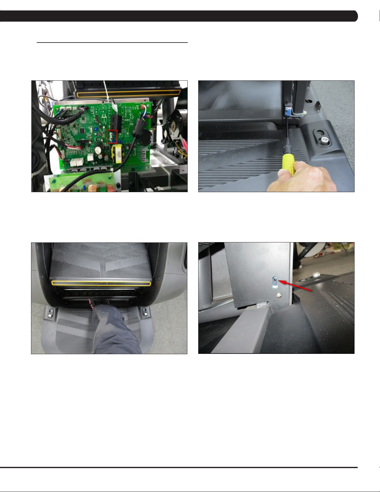
1) Turn off power and disconnect the cord from the machine.
2) Remove the service cover as outlined in Section 5.1.
3) Remove the proximity sensor cable from the LCB, and cut any wire ties holding the cable to the frame (Figure A).
4) Remove the 2 screws holding the proximity sensor to the frame (Figure B), and remove the proximity sensor.
FIGURE A FIGURE B
5) Reverse Steps 1-4 to install a new proximity sensor. NOTE: The proximity sensor should be installed so that there is a gap of less or
equal than 2mm between the sensor and the axle (Figure B).
6) Once the proximity sensor is installed, rotate the stairs at least 2 complete revolutions to make sure the sensor does not hit. NOTE: The
sensor has a signal LED located near the mounting screws. The sensor should be mounted close enough to trigger this LED.
7) Test the Climb Mill for function as outlined in Section 5.19.
42
Page 45
CHAPTER 5: PART REPLACEMENT GUIDE
5.18 IR SENSOR REPLACEMENT
1) Turn off the power and disconnect the cord from the machine.
2) Remove the service cover as outlined in Section 5.1.
3) Remove the side covers as outlined in Section 5.2.
4) Remove the IR sensor cable from the LCB, and cut any wire ties holding the cable to the LCB (Figure A).
5) Remove the 2 screws holding the IR sensor to the frame (Figure B), and cut any wire ties holding the cable to the frame.
FIGURE A FIGURE B
6) Reverse Steps 1-5 to install a new IR sensor. NOTE: When re-installing the IR sensor, make sure that the IR sensor with black wire (2
pin) is on the left (transmission) and the other IR sensor with gray wire (3 pin) is on the right (receiver).
7) Once the IR sensor is installed, Press the GO key and begin using the machine. Put your foot in the middle of the IR sensors (transmission
& receiver) to test whether the sensors are working enough to stop machine (Figure C). NOTE: The sensor has an eye. The eyes of two
sensors should be mounted facing each other so that interrupting their path will stop the machine (Figure D).
FIGURE C FIGURE D
8) Test the Climb Mill for function as outlined in Section 5.19.
43
Page 46

CHAPTER 5: PART REPLACEMENT GUIDE
5.19 TESTING THE CLIMB MILL
ONCE THE UNIT OR REPLACEMENT PART IS FULLY INSTALLED AND ASSEMBLED AND
PROPERLY PLACED ON THE FLOOR, USE THE FOLLOWING INSTRUCTIONS TO TEST
THE MACHINE:
1) To enter Engineering Mode, input the serial number of the console and frame. Also set the Machine Type and verify that the Date and Time
are correct.
2) Press the GO key and begin using the machine. Stand on the machine and hold the handlebars while initiating movement to simulate
exercising. While moving listen for any odd noises or squeaks.
3) Grasp the hand grips to check for proper heart rate response.
4) Press the LEVEL UP and LEVEL DOWN keys from hand grip to make sure resistance is fully functional.
5) Try stepping off the unit to make sure the proximity sensor is fully functional. Also test the STOP key on the grip, IR sensor, Control Zone and
Emergency Stop key (on console mast and lower handlebar) for function. .
44
Page 47

CHAPTER 6: SOFTWARE UPGRADE PROCEDURE
6.1 XIR/XER SOFTWARE UPGRADE PROCEDURE FROM USB
1) Copy the XIR or XR console software onto the USB drive (Figure A).
2) Unzip the XIR or XR console software onto the USB drive (Figure B).
3) Insert the USB Drive into the USB port in the console (Figure C).
4) Enter service mode by pressing the LEVEL UP and LEVEL DOWN keys from hand grip. Then select the Update and update source "Update
from USB" (Figure D).
5) Press the "Install" to auto run the upgrade process (Figure E).
6) When update is complete and machine will automatically returns to the standard display, turn off the machine.
7) Wait 30 seconds before turning on machine.
FIGURE A FIGURE B
FIGURE C
FIGURE D
FIGURE E
45
Page 48

CHAPTER 6: SOFTWARE UPGRADE PROCEDURE
6.2 XIR/XER SOFTWARE UPGRADE PROCEDURE FROM WEBSITE
1) Enter service mode by pressing the LEVEL UP and LEVEL DOWN keys from the hand grip. Then select the Update and update source
"Check for Update" (Figure A).
2) Press the "Install" to auto run the upgrade process (Figure B).
3) When update is complete and machine will automatically returns to the standard display, turn off the machine.
4) Wait 30 seconds before turning on machine.
FIGURE A FIGURE B
46
Page 49

CHAPTER 6: SOFTWARE UPGRADE PROCEDURE
6.3 XR SOFTWARE UPGRADE PROCEDURE FROM USB
1) Create a file on the USB flash drive which will be used. The folders should be MATRIX\FW (create a folder called MATRIX, then a folder in
MATRIX called FW (Figure A).
2) Edit the XR UCB software file name to “EFM.bin”, then copy the software file into the FW folder on the USB flash drive (the access should
read \MATRIX\FW (Figure B).
3) Insert the USB flash drive into the USB port on the UCB (Figure C).
4) Once the console display shows “software update press enter”, press ENTER key (Figure D) and the upgrade procedure will start (Figure E).
5) After the console beeps and comes back home screen, please remove the USB drive and make sure the software version is correct.
FIGURE A FIGURE B
FIGURE C
FIGURE D
FIGURE E
FIGURE F
47
Page 50

CHAPTER 7: DOCUMENT UPDATE HISTORY
7.1 DOCUMENT UPDATE HISTORY
Version Date Change Description
0 2018/09/4 Service manual draft released.
48
Page 51

NOTES
49
Page 52

50
MATRIX FITNESS SYSTEMS CORP.
1610 LANDMARK DRIVE COTTAGE GROVE WI 53527 USA
REV. 01
KO
 Loading...