

Page 1

2016 7XE/7XI
CONSOLE
SERVICE MANUAL
Page 2

TABLE OF CONTENTS
CHAPTER 1: SERIAL NUMBER LOCATION ........................................................... 1
CHAPTER 2: IMPORTANT SAFETY INSTRUCTIONS
2.1 Electrical Requirements ............................................................................................. 2
CHAPTER 3: PREVENTATIVE MAINTENANCE
3.1 Recommended Cleaning Tips .................................................................................... 3
3.2 Check for Damaged Parts ......................................................................................... 3
CHAPTER 4: CONSOLE OVERLAY AND WORKOUT DESCRIPTION
4.1 Console Description .................................................................................................. 4
4.2 7xe/7xi Console Operation ......................................................................................... 8
CHAPTER 5: MANAGER MODE
5.1 Using Manager Mode ................................................................................................ 14
5.2 Manager Mode Overview ........................................................................................... 15
CHAPTER 6: ENGINEERING MODE
6.1 Using Engineering Mode ........................................................................................... 19
6.2 Engineering Mode Overview ...................................................................................... 20
CHAPTER 7: SERVICE MODE / TEST MODE
7.1 Using Service Mode. .................................................................................................. 24
7.2 Service Mode Overview ............................................................................................. 25
CHAPTER 8: TROUBLESHOOTING
8.1 Electrical Diagram ...................................................................................................... 29
8.2 Error Code List ............................................................................................................ 36
CHAPTER 9: PART REPLACEMENT GUIDE
9.1 Working Environment Set Up for Parts Replacement................................................. 41
9.2 T7xe UCB Replacement ............................................................................................. 42
9.3 T7xe TFT-LCD Module Replacement ......................................................................... 43
9.4 7xe UCB REPLACEMENT .......................................................................................... 44
9.5 7xe TFT-LCD Module Replacement ........................................................................... 45
9.6 T7xi UCB Module Replacement .................................................................................. 46
9.7 T7xi TFT-LCD Module Replacement .......................................................................... 47
9.8 7xi UCB REPLACEMENT ........................................................................................... 48
9.9 7xi TFT-LCD Module Replacement ............................................................................. 49
CHAPTER 10: CONSOLE SPECIFICATIONS AND ASSEMBLY GUIDE
10.1 VA installation .............................................................................................................. 50
10.2 RFID installation .......................................................................................................... 52
10.3 TV Programming Instructions .................................................................................... 57
10.4 US and KM tuner setting SOP (ATSC, DVB-T/T2/C/S, ISDB-T source) .................... 58
10.5 IPTV setting SOP ........................................................................................................ 63
10.6 TV (Pro:Idiom) setting SOP ........................................................................................ 72
CHAPTER 11: SOFTWARE UPGRADE PROCEDURE
11.1 Software Upgrade Procedure from USB ..................................................................... 74
11.2 Software Upgrade Procedure from Website ............................................................... 75
Page 3
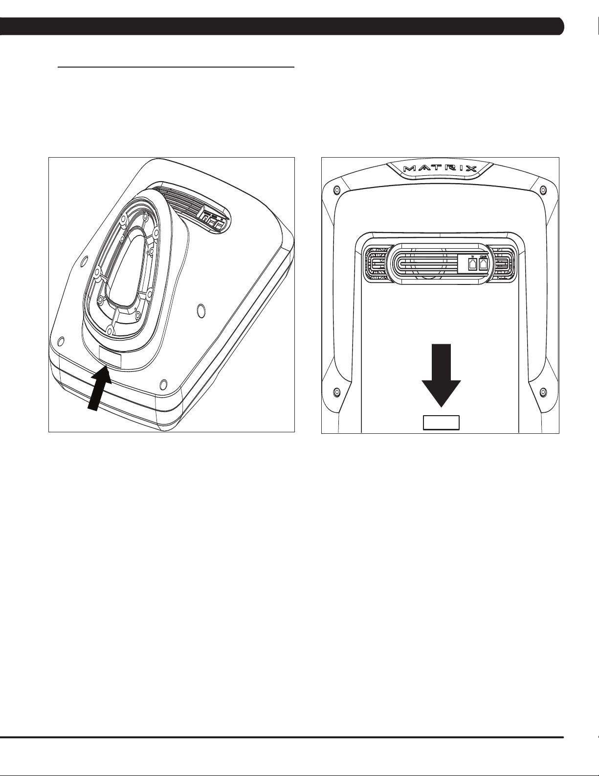
1.1 SERIAL NUMBER LOCATION
CHAPTER 1: SERIAL NUMBER LOCATION
CONSOLE SERIAL NUMBER LOCATION
7XE / 7XI
T7XE / T7XI
1
Page 4
CHAPTER 2: IMPORTANT SAFETY INFORMATION
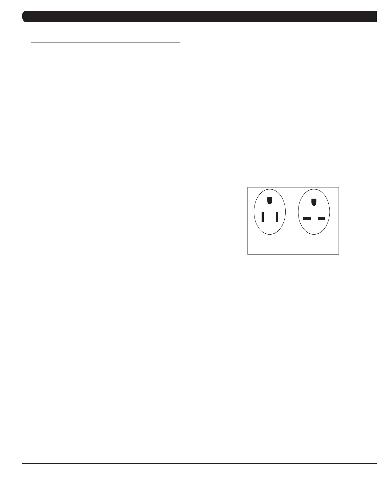
220 NEMA 6-15P
PLUG
110 NEMA 5-15P
PLUG
2.1 ELECTRICAL REQUIREMENTS
DEDICATED CIRCUIT AND ELECTRICAL INFO
A “Dedicated Circuit” means that each outlet you plug into should not have anything else running on that same circuit. The easiest way to verify
this is to locate the main circuit breaker box, and turn off the breaker(s) one at a time. Once a breaker has been turned off, the only thing that
should not have power to it are the units in question. No lamps, vending machines, fans, sound systems, or any other item should lose power
when you perform this test. Non-looped (isolated) neutral/grounding means that each circuit must have an individual neutral/ground connection
coming from it, and terminating at an approved earth ground. You cannot “jumper” a single neutral/ground from one circuit to the next.
ELECTRICAL REQUIREMENTS
For your safety and to ensure good unit performance, the ground on this circuit must be non-looped (isolated). Please refer to NEC article 210-21
and 210-23. Any alterations to the standard power cord provided could void all warranties of this product.
The 3x, 5x and 7xe bikes are designed to be self-powered and do not require an external power supply source to operate. Without an external
power supply, the console’s start-up time may be delayed. Add-on TV’s and other console accessories will increase the time needed for start-up.
An external power supply will ensure power is provided to the console at all times and is recommended when add-on accessories are used.
For units with an integrated TV (like the 7xe and 7xi), the TV power requirements are included in the unit. An RG6 coaxial cable with ‘F Type’
compression fittings on each end will need to be connected to the cardio unit and the video source. Additional power requirements are not needed
for the add-on digital TV (3x and 5x). For units with an add-on PCTV (3x and 5x), the TV power requirements are separate.
NOTE: ALL UNITS WITH VIRTUAL ACTIVE™ MUST BE POWERED!
110 V UNITS
All Matrix 3x, 5x, 7xe and 7xi 110 V bikes require the use of a 100-125 V, 60 Hz and a 15 A
“Dedicated Circuit”, with a non-looped (isolated) neutral/ground for power. This outlet should be a
NEMA 5-15R and have the same configuration as the plug. No adapter should be used with this
product. These bikes can be daisy-chained together with up to 4 units per 15 A dedicated circuit.
Matrix daisy-chain cord adapters are sold separately.
220 V UNITS
All Matrix 3x, 5x, 7xe and 7xi 220 V bikes require the use of a 216-250 V, 50 Hz and a 15 A
“Dedicated Circuit”, with a non-looped (isolated) neutral/ground for power. This outlet should be a
NEMA 6-15R and have the same configuration as the plug. No adapter should be used with this
product. These bikes can be daisy-chained together with up to 4 units per 15 A dedicated circuit.
Matrix daisy-chain cord adapters are sold separately.
GROUNDING INSTRUCTIONS
The unit must be grounded. If it should malfunction or breakdown, grounding provides a path of
least resistance for electric current to reduce the risk of electric shock. The unit is equipped with a cord having an equipment-grounding conductor and a grounding plug. The plug must be plugged into an appropriate outlet that is properly installed and grounded in accordance with all local
codes and ordinances. If the user does not follow these grounding instructions, the user could void the Matrix limited warranty.
North American power cord plugs shown.
Depending on your country, the plug type may vary.
ADDITIONAL ELECTRICAL INFO
In addition to the dedicated circuit requirement, the proper gauge wire must be used from the circuit breaker box, to each outlet that will have the
maximum number of units running off of it. If the distance from the circuit breaker box to each outlet, is 100 ft (30.5 m) or less, then 12 gauge wire
should be used. For distances greater than 100 ft (30.5 m) from the circuit breaker box to the outlet, a 10 gauge wire should be used.
ENERGY SAVING / LOW-POWER MODE
All units are configured with the ability to enter into an energy saving / low-power mode when the unit has not been in use for a specified period
of time. Additional time may be required to fully reactivate this unit once it has entered the low-power mode. This energy saving feature may be
enabled or disabled from within the ‘Manager Mode’ or ‘Engineering Mode.
2
Page 5

CHAPTER 3: PREVENTATIVE MAINTENANCE
3.1 RECOMMENDED CLEANING TIPS
In order to maximize life span, and minimize down time, all Matrix Fitness Equipment requires regularly
scheduled cleaning.
YOU WILL NEED:
- Mild dish soap and water mixture in a spray bottle (per manufacturers recommend ratio).
- Lint free 100% cotton cleaning cloths or Microfiber cleaning cloths.
DAILY:
1. Wipe down the unit after each use with a mild dish soap and water mixture. NOTE: Spray the soap/water mixture onto the cloth. NEVER
spray directly onto the equipment. We recommend that you do NOT allow customers to use spray bottles to clean the equipment. If the
cleaner is sprayed directly on the equipment or overspray is present, it may cause your equipment to rust and/or cause damage to console
overlays.
WEEKLY:
1. With a clean dry 100% lint free cloth and water / soap mixture, wipe down the entire console area including the hand grips and hand rails.
3.2 CHECK FOR DAMAGED PARTS
DO NOT use any equipment that is damaged or has worn or broken parts. Use only replacement parts supplied by Matrix Fitness Systems.
MAINTAIN LABELS AND NAMEPLATES. Do not remove labels for any reason. They contain important information. If unreadable or missing,
contact Matrix Fitness for a replacement. 1-866-693-4863, www.matrixfitness.com
MAINTAIN ALL EQUIPMENT Preventative maintenance is the key to smooth operating equipment. Equipment needs to be inspected at regular
intervals. Defective components must be replaced immediately. Improperly working equipment must be kept out of use until it is repaired.
Ensure that any person(s) making adjustments or performing maintenance or repair of any kind is qualified to do so. Matrix Fitness Systems will
provide service and maintenance training at our corporate facility upon request or in the field if proper arrangements are made.
3
Page 6

CHAPTER 4: CONSOLE OVERLAY AND WORKOUT DESCRIPTION
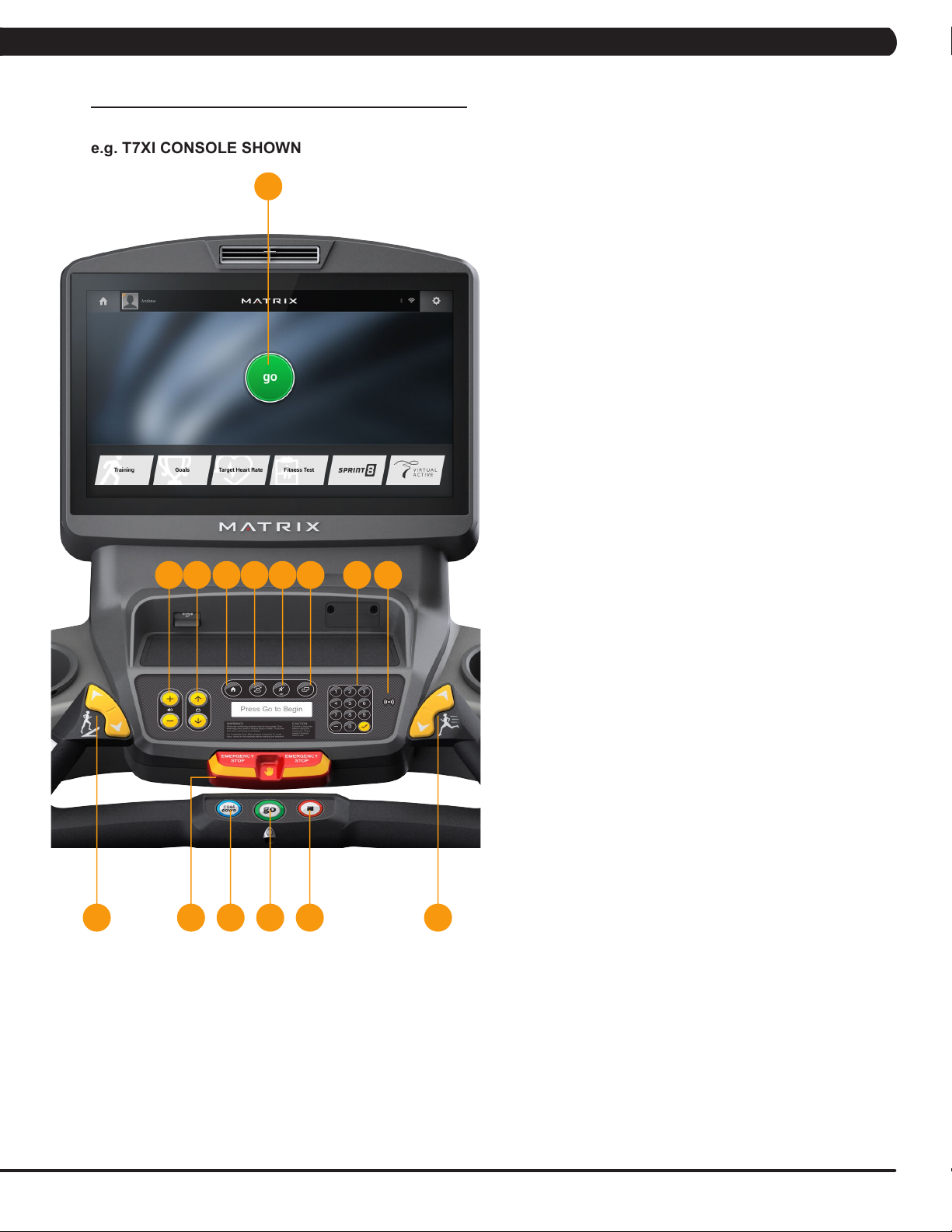
4.1 CONSOLE DESCRIPTION
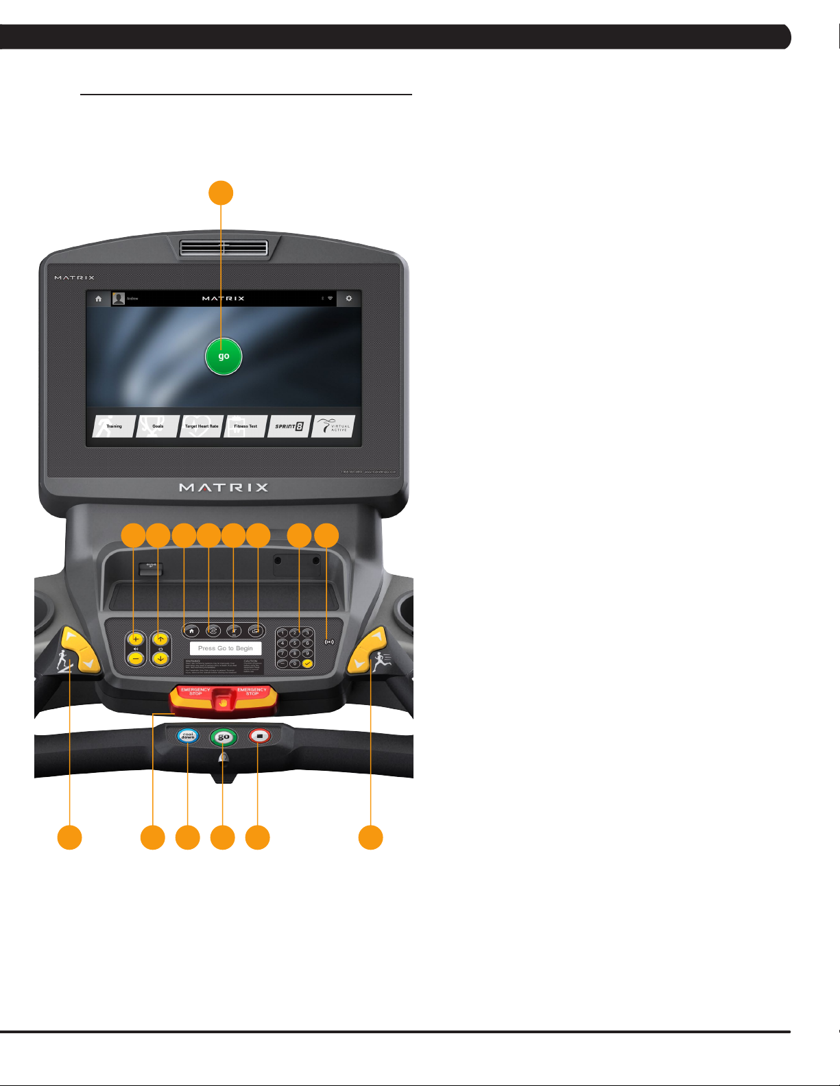
e.g. A7XE CONSOLE SHOWN
A
7XE CONSOLE DESCRIPTION
The Matrix machine is inspected before it is packaged. It is shipped in
two pieces: the base and the console. Carefully unpack the unit and
dispose of the box material. Note: There is a thin protective sheet of
clear plastic on the overlay of the console that should be removed
before use.
The 7xe has a fully integrated touch screen display. All information
required for workouts is explained on screen. Exploration of the
interface is highly encouraged. The information explaining how to
program for various workouts will give an explanation about the
contents of each screen on the 7xe.
A) GO: One Touch Start.
B) STOP (displayed on-screen during workout): Ends workout and
shows workout summary data.
C) COOL DOWN (displayed on-screen during workout): Puts unit
into Cool Down mode. Cool Down time is dependent on the
workout.
F IG HED J K
7XE ENTERTAINMENT ZONE
D) VOLUME UP/DOWN: Adjusts the volume output through
headphones.
E) CHANNEL UP/DOWN: Allows for channel selection on the
integrated console TV.
F) HOME: Will take the user back to the home screen.
G) LAST CHANNEL: Allows the user to cycle between the current
channel and the previous channel they were viewing.
H) CC/MUTE: Mutes sound and turns closed captioning on or off.
I) DISPLAY MODE: Allows user to cycle through display modes.
J) NUMBER KEYPAD: Allows for easy number inputs.
K) RFID SENSOR: Wireless login access location (optional add-
on feature).
4
Page 7
CHAPTER 4: CONSOLE OVERLAY AND WORKOUT DESCRIPTION
4.1 CONSOLE DESCRIPTION - CONTINUED
e.g. T7XE CONSOLE SHOWN
T7XE CONSOLE DESCRIPTION
A
LI J KHG
NM
The Matrix machine is inspected before it is packaged. It is shipped in
two pieces: the base and the console. Carefully unpack the unit and
dispose of the box material. Note: There is a thin protective sheet of
clear plastic on the overlay of the console that should be removed
before use.
The T7xe has a fully integrated touch screen display. All information
required for workouts is explained on screen. Exploration of the
interface is highly encouraged. The information explaining how to
program for various workouts will give an explanation about the
contents of each screen on the T7xe.
A) GO: One Touch Start.
B) STOP: Ends workout and shows workout summary data.
C) INCLINE TOGGLES: Adjust incline during workout.
D) SPEED TOGGLES: Adjust speed during workout.
E) COOL DOWN: Puts treadmill into Cool Down mode. Cool
Down time is dependent on the length of the workout. Workouts
19 minutes and shorter will have a cool down length of 2
minutes. Workouts 20 minutes and longer will have a cool down
length of 5 minutes.
F) EMERGENCY STOP / IMMOBILIZATION: To stop all functions
and immobilize the unit. The emergency stop on this treadmill
must be returned to its original position in order to allow normal
operation of the unit.
C D
AE BF
T7XE ENTERTAINMENT ZONE
G) VOLUME UP/DOWN: Adjusts the volume output through
headphones.
H) CHANNEL UP/DOWN: Allows for channel selection on the
integrated console TV.
I) HOME: Will take the user back to the home screen.
J) LAST CHANNEL: Allows the user to cycle between the current
channel and the previous channel they were viewing.
K) CC/MUTE: Mutes sound and turns closed captioning on or off.
L) DISPLAY MODE: Allows user to cycle through display modes.
M) NUMBER KEYPAD: Allows for easy number inputs.
N) RFID SENSOR: Wireless login access location (optional add-
on feature).
5
Page 8
CHAPTER 4: CONSOLE OVERLAY AND WORKOUT DESCRIPTION
4.1 CONSOLE DESCRIPTION - CONTINUED
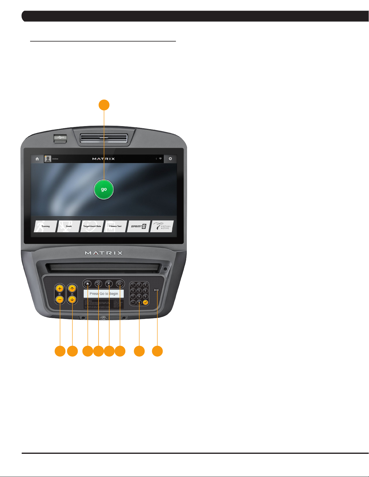
e.g. A7XI CONSOLE SHOWN
A
7XI CONSOLE DESCRIPTION
The Matrix machine is inspected before it is packaged. It is shipped in
two pieces: the base and the console. Carefully unpack the unit and
dispose of the box material. Note: There is a thin protective sheet of
clear plastic on the overlay of the console that should be removed
before use.
The 7xi has a fully integrated touch screen display. All information
required for workouts is explained on screen. Exploration of the
interface is highly encouraged. The information explaining how to
program for various workouts will give an explanation about the
contents of each screen on the 7xi.
A) GO: One Touch Start.
B) STOP (displayed on-screen during workout): Ends workout and
shows workout summary data.
C) COOL DOWN (displayed on-screen during workout): Puts unit
into Cool Down mode. Cool Down time is dependent on the
workout.
F IG HED J K
7XI ENTERTAINMENT ZONE
D) VOLUME UP/DOWN: Adjusts the volume output through
headphones.
E) CHANNEL UP/DOWN: Allows for channel selection on the
integrated console TV.
F) HOME: Will take the user back to the home screen.
G) LAST CHANNEL: Allows the user to cycle between the current
channel and the previous channel they were viewing.
H) CC/MUTE: Mutes sound and turns closed captioning on or off.
I) DISPLAY MODE: Allows user to cycle through display modes.
J) NUMBER KEYPAD: Allows for easy number inputs.
K) RFID SENSOR: Wireless login access location (optional add-
on feature).
6
Page 9
CHAPTER 4: CONSOLE OVERLAY AND WORKOUT DESCRIPTION
4.1 CONSOLE DESCRIPTION - CONTINUED
e.g. T7XI CONSOLE SHOWN
A
LI J KHG
NM
T7XI CONSOLE DESCRIPTION
The Matrix machine is inspected before it is packaged. It is shipped in
two pieces: the base and the console. Carefully unpack the unit and
dispose of the box material. Note: There is a thin protective sheet of
clear plastic on the overlay of the console that should be removed
before use.
The T7xi has a fully integrated touch screen display. All information
required for workouts is explained on screen. Exploration of the
interface is highly encouraged. The information explaining how to
program for various workouts will give an explanation about the
contents of each screen on the T7xi.
A) GO: One Touch Start.
B) STOP: Ends workout and shows workout summary data.
C) INCLINE TOGGLES: Adjust incline during workout.
D) SPEED TOGGLES: Adjust speed during workout.
E) COOL DOWN: Puts treadmill into Cool Down mode. Cool
Down time is dependent on the length of the workout. Workouts
19 minutes and shorter will have a cool down length of 2
minutes. Workouts 20 minutes and longer will have a cool down
length of 5 minutes.
F) EMERGENCY STOP / IMMOBILIZATION: To stop all functions
and immobilize the unit. The emergency stop on this treadmill
must be returned to its original position in order to allow normal
operation of the unit.
C D
AE BF
T7XI ENTERTAINMENT ZONE
G) VOLUME UP/DOWN: Adjusts the volume output through
headphones.
H) CHANNEL UP/DOWN: Allows for channel selection on the
integrated console TV.
I) HOME: Will take the user back to the home screen.
J) LAST CHANNEL: Allows the user to cycle between the current
channel and the previous channel they were viewing.
K) CC/MUTE: Mutes sound and turns closed captioning on or off.
L) DISPLAY MODE: Allows user to cycle through display modes.
M) NUMBER KEYPAD: Allows for easy number inputs.
N) RFID SENSOR: Wireless login access location (optional add-
on feature).
7
Page 10
CHAPTER 4: CONSOLE OVERLAY AND WORKOUT DESCRIPTION
4.2 7XE/7XI CONSOLE OPERATION
7XE/7XI CONSOLE OPERATION
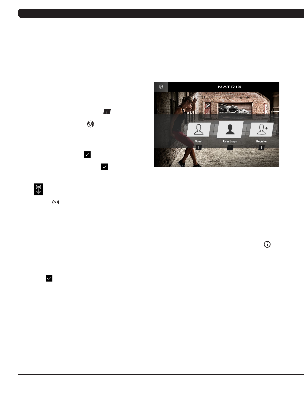
GETTING STARTED
• Touch the USER button to sign-in with your XID.
• Touch the GUEST button to workout anonymously.
• Touch the REGISTER button to create a new XID.
• For help or more information, touch .
• To change language, touch
.
USER SIGN-IN
1) Enter your XID and touch
2) Enter your PASSCODE and touch
Consoles equipped with RFID will have this
symbol in the lower-right corner of the display.
To log in, touch your RFID tag to the symbol
located on the bottom right of the console.
.
.
LOGIN SCREEN
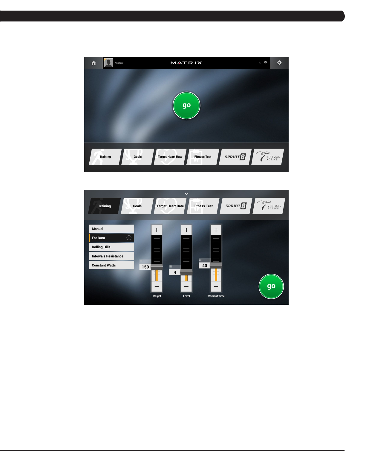
GO SCREEN
• Touch GO to begin working out immediately. Or...
• Touch the WORKOUT CATEGORY button of
your choice to customize your workout.
REGISTER A NEW USER
1) Don’t have an xID account? Registration is easy.
2) Follow the on-screen prompts to create your free
account.
3) Review your information and select the I
ACCEPT THE TERMS AND CONDITIONS
box to review the Terms and Conditions.
4) Touch
account is now active and you are signed-in.
to complete registration. Your
PROGRAM SETUP
1) After selecting a WORKOUT CATEGORY button, select
one of the PROGRAMS listed to the left.
For more information on a selected program, touch .
2) Use the SLIDER CONTROLS to
adjust your program settings.
3) Press GO to begin your workout.
Note: Workouts and features vary based on
model type, console configurations, software
versions and options purchased.
* Supported standards with carrier frequency of 13.56 MHz
include; ISO 14443 A, ISO 15693, ISO 14443 B, Sony
Felica, Inside Contactless (HID iClass), and LEGIC RF.
8
Page 11
CHAPTER 4: CONSOLE OVERLAY AND WORKOUT DESCRIPTION
4.2 7XE/7XI CONSOLE OPERATION - CONTINUED
GO SCREEN
PROGRAM SETUP
Note: Workouts and features vary based on model type, console configurations, software versions and options purchased.
9
Page 12
CHAPTER 4: CONSOLE OVERLAY AND WORKOUT DESCRIPTION
4.2 7XE/7XI CONSOLE OPERATION - CONTINUED
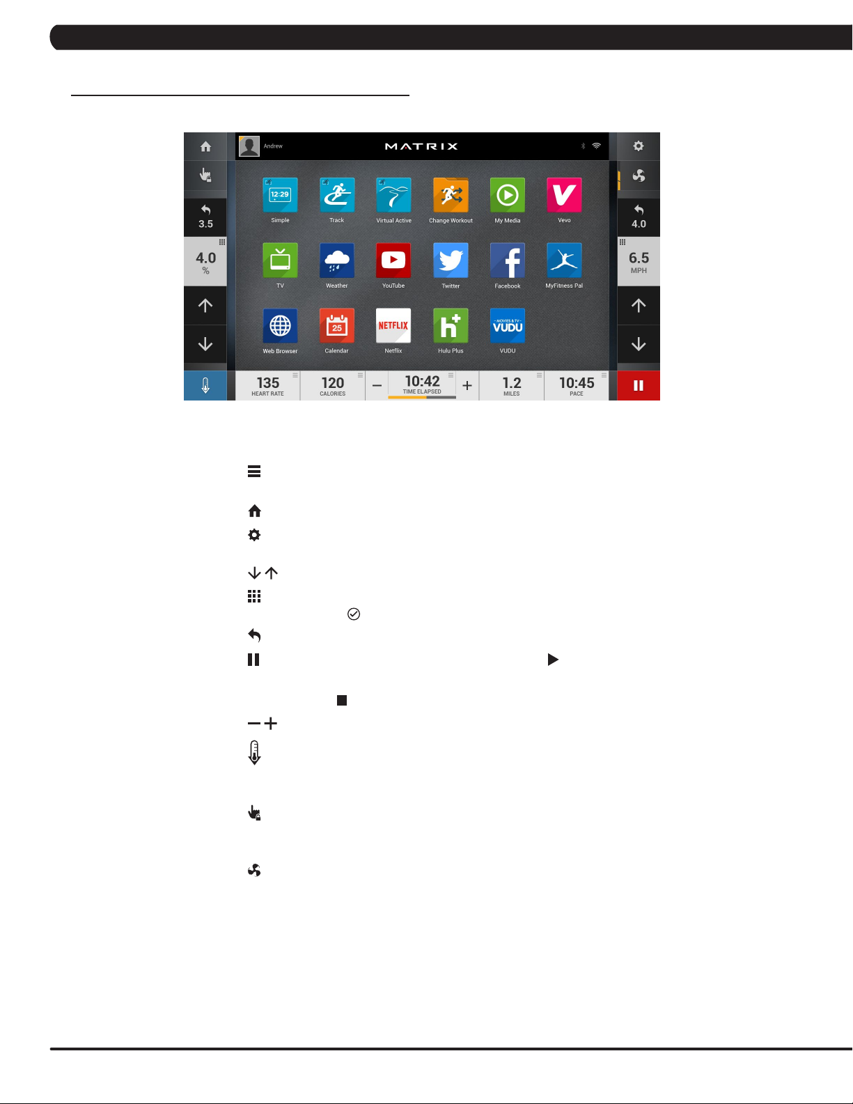
HOMESCREEN
• The USERNAME or GUEST is shown in the upper left corner.
• Touch to change WORKOUT STATISTICS
displayed at the bottom of the screen.
• Touch to go back to the home screen whenever you’re using an app.
• Touch
change AUDIO SOURCE (TV, My Media, Virtual Active, etc.).
• Touch to increase or decrease the intensity level, speed or incline.
• Touch to use the keypad to set intensity level,
speed or incline. Press
• Touch to change intensity level, speed or incline back to previous setting.
• Touch to temporarily pause your workout and touch to resume.
NOTE: After resuming, speed, incline and intensity levels will be reset.
• While paused, touch to end workout.
• Touch to increase or decrease the duration of your workout.
to adjust VOLUME, pair a BLUETOOTH device or to
HOMESCREEN
to confirm change.
10
• Touch
for a few minutes while reducing the workout intensity,
allowing your body to recover from your workout.
• Touch to lock the screen in order to prevent accidental
screen touches from being implemented. Touch it again
to unlock the screen and allow screen touches.
• Touch to turn the fan on. There are three fan speeds (low, medium, high).
Note: Workouts and features vary based on model type, console
configurations, software versions and options purchased.
to enter cool down mode. Cool down lasts
Page 13
CHAPTER 4: CONSOLE OVERLAY AND WORKOUT DESCRIPTION
4.2 7XE/7XI CONSOLE OPERATION - CONTINUED
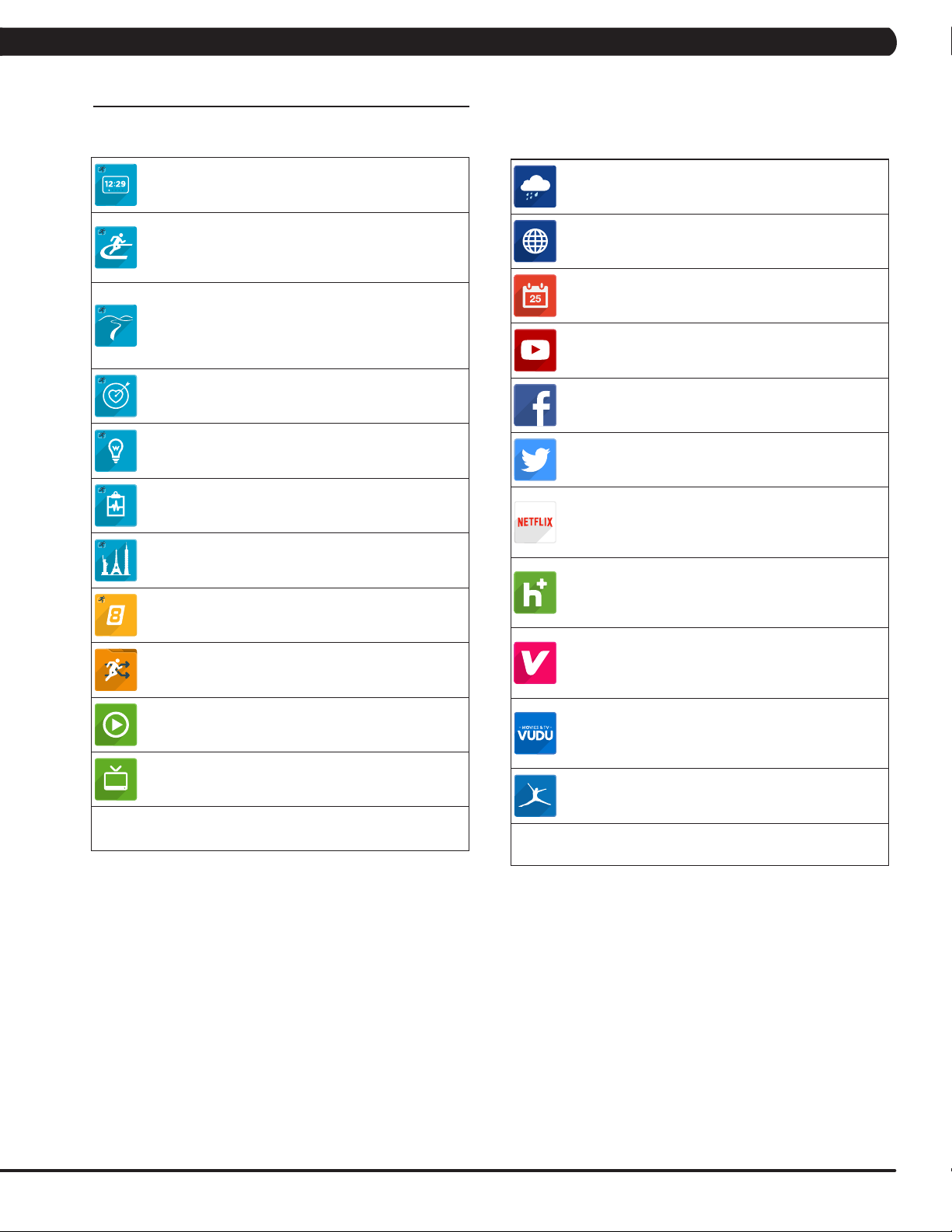
APPS AND ENTERTAINMENT
SIMPLE
Workout stats are displayed in
3 customizeable windows.
TRACK
Displays a 400 m (1/4 mile) track. Split
feature allows you to keep track of your
fastest laps and improve your time.
VIRTUAL ACTIVE
Your workout info is displayed and Virtual
Active courses are shown. With Virtual Active,
escape the confines of an ordinary workout as
you or walk or run through exotic destinations.
TARGET HEART RATE
Track your progress while working out
to a Target Heart Rate program.
CONSTANT WATTS
Track your progress while working
out to a Constant Watts program.
FITNESS TEST
Track your progress while working
out to a Fitness Test program.
LANDMARKS
Track your progress while working
out to a Landmarks program.
SPRINT 8
Track your progress while working
out to a Sprint 8 program.
CHANGE WORKOUT
Select a different workout without
stopping your current workout.
MY MEDIA
Connect and control audio and video files
on-screen via USB port or Bluetooth.
TV
Watch live TV.
WEATHER
Get local weather info.
WEB BROWSER
Access the world wide web
while you work out.
FACILITY CALENDAR
View Facility event schedule and other info.
YOUTUBE
Browse and watch YouTube
videos while you work out.
FACEBOOK
Browse your Facebook page
while you work out.
TWITTER
Access your Twitter feed while you work out.
NETFLIX
Browse and watch Netflix videos while you
work out.
Netflix account required to access content.
HULU PLUS
Browse and watch Hulu Plus videos
while you work out.Hulu Plus account
required to access content.
VEVO
Browse and watch Vevo videos
while you work out.Vevo account
required to access content.
VUDU
Browse and watch Vudu videos
while you work out.Vudu account
required to access content.
MYFITNESS PAL
Lose weight with MyFitnessPal, the fastest
and easiest to use calorie counter.
Note: Workouts and features vary based on
model type, console configurations, software
versions and options purchased.
11
Page 14
CHAPTER 4: CONSOLE OVERLAY AND WORKOUT DESCRIPTION
4.2 7XE/7XI CONSOLE OPERATION - CONTINUED
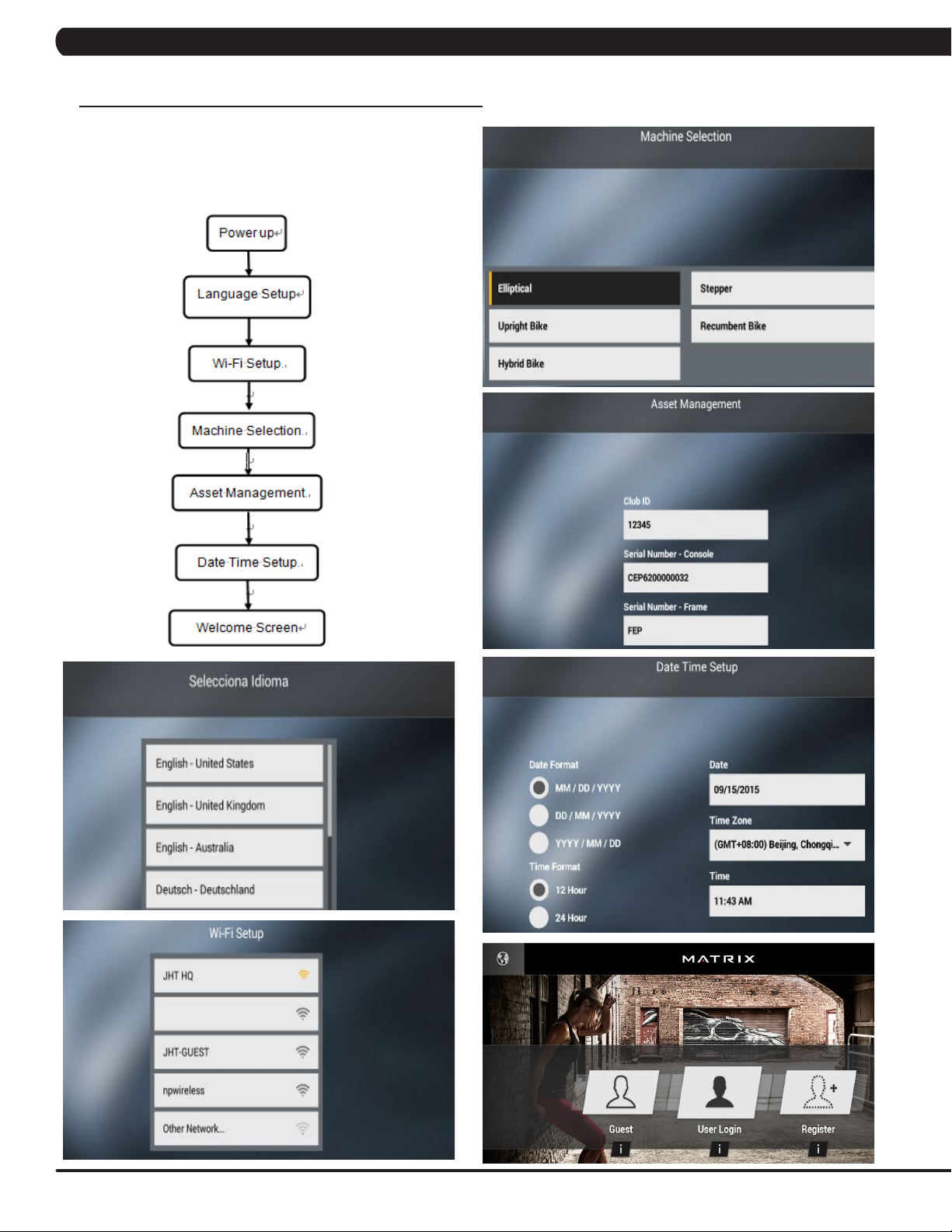
FIRST TIME SETUP SCREENS
To enter "Restore Factory Defaults" setting, press "ENTER, 3, 0, 0,
2, ENTER" on the number keypad and Factory Defaults setting will
appear on the display.
12
Page 15

CHAPTER 4: CONSOLE OVERLAY AND WORKOUT DESCRIPTION
4.2 7XE/7XI CONSOLE OPERATION - CONTINUED
NOTE:
This equipment has been tested and found to comply with the limits for a Class B digital device, pursuant to part 15 of the FCC rules.
These limits are designed to provide reasonable protection against harmful interference in a residential installation. This equipment
generates, uses and can radiate radio frequency energy and, if not installed and used in accordance with the instructions, may
cause harmful interference to radio communications. However, there is no guarantee that interference will not occur in a particular
installation. If this equipment does cause harmful interference to radio or television reception, which can be determined by turning
the equipment off and on, the user is encouraged to try to correct the interference by one or more of the following measures:
• Reorient or relocate the receiving antenna.
• Increase the separation between the equipment and receiver.
• Connect the equipment into an outlet on a circuit different from that to which the receiver is connected.
• Consult the dealer or an experienced radio/TV technician for help.
Any changes or modifications not expressly approved by the party responsible for
compliance could void the user’s authority to operate this equipment.
FCC RF Radiation Exposure Statement:
1. This Transmitter must not be co-located or operating in conjunction with any other antenna or transmitter.
2. This equipment complies with FCC RF radiation exposure limits set forth for an uncontrolled environment. This equipment
should be installed and operated with a minimum distance of 20 centimeters between the radiator and your body.
13
Page 16
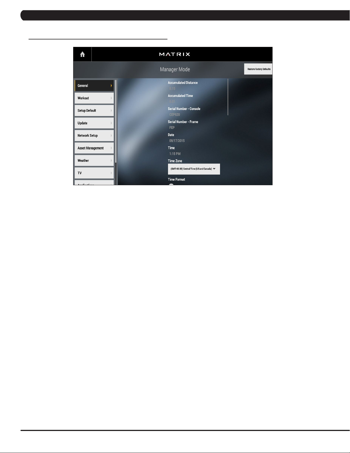
5.1 USING MANAGER MODE
CHAPTER 5: MANAGER MODE
1) To enter Manager Mode, press "ENTER, 1, 0, 0, 1, ENTER" on the number keypad and Manager Mode will appear on the display.
2) Manager Mode is divided into 9 tabs, located on the left side of the screen. They are General, Workout, Setup Defaults, Network Setup,
Asset Management, Weather, TV, Applications, Hardware and Service.
3) Choose a tab by touching the screen over the desired tab.
4) Each of the tabs has options that will appear once you have chosen that particular tab.
5) Press the "HOME" button or the EMERGENCY STOP to exit Manager Mode.
14
Page 17
CHAPTER 5: MANAGER MODE
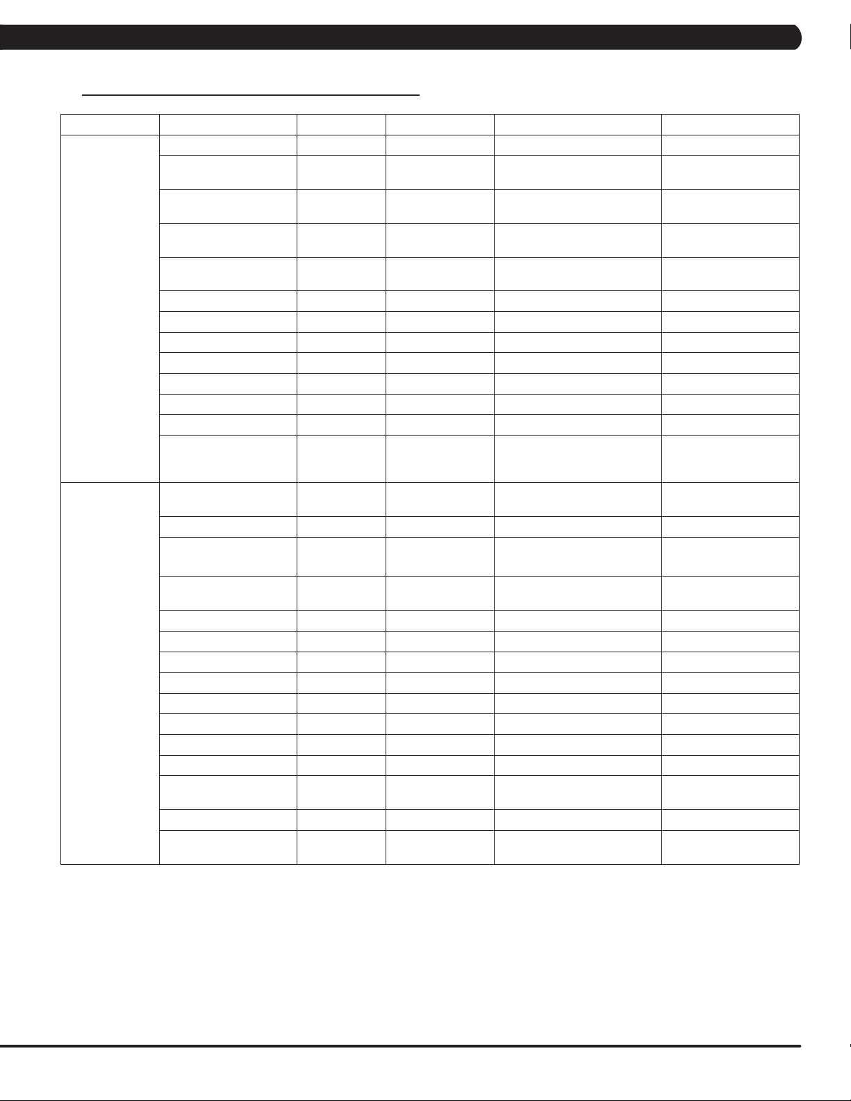
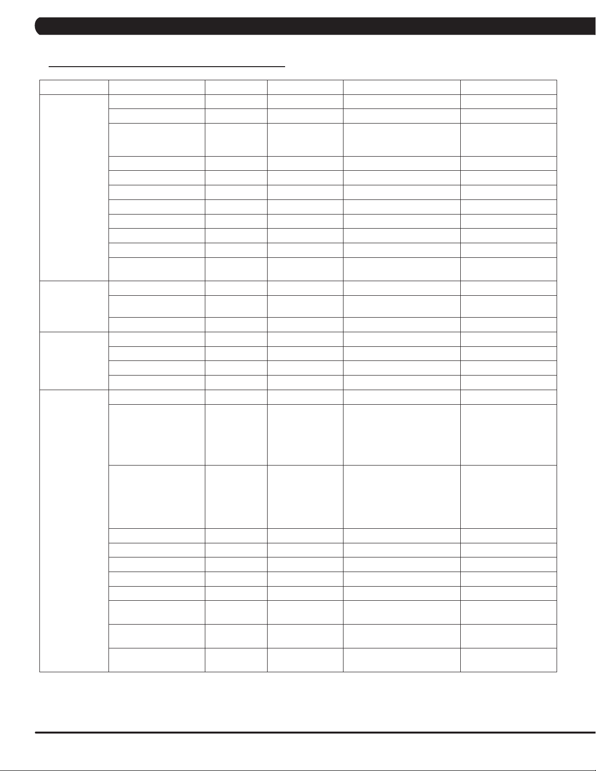
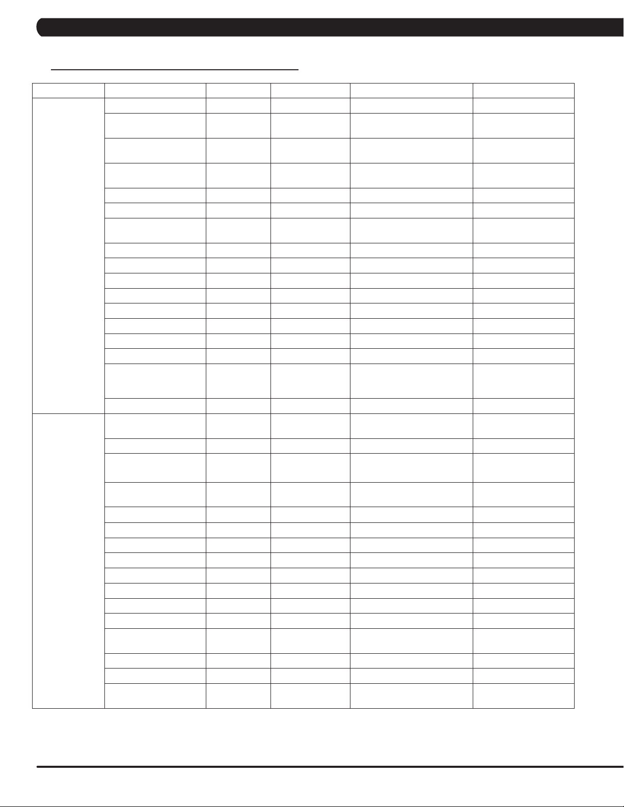
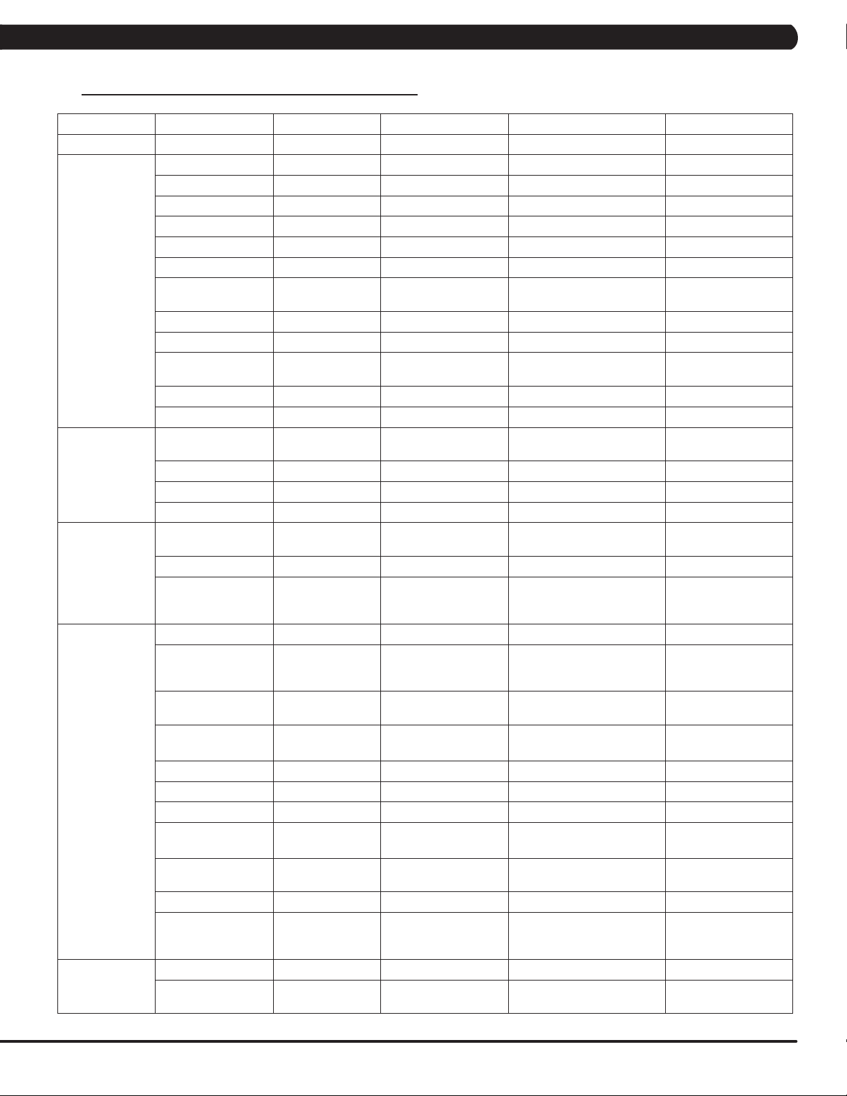
5.2 MANAGER MODE OVERVIEW
Category Name Models Default Range Units
Accumulated Time TACSEHUR 0 - Hours
(TAEHU)Miles/Km
(CS)Floors
-
MPH/KPH
Miles/Km
Feet
General
Workouts
Accumulated Distance TACSEHUR 0 -
Serial Number - Console TACSEHUR
Serial Number - Frame TACSEHUR
Date TACSEHUR RTC Date
Time TACSEHUR RTC Time 00-23:00-59:00-59 12hr/24hr
Time Zone TACSEHUR Central Time - -
Time Format TACSEHUR 12 Hour 12 Hour, 24 Hour -
Screen Timeout TACSEHUR 30 15-120, Never Seconds
Software Version History TACSEHUR - - -
Firmware Versions TACSEHUR - - -
Language Setup TACSEHUR English (U.S.) See Languages Table -
Social Network Post TACSEHUR
Keyboard Disable
Threshold
Maximum Workout Time TACSEHUR 60 10-120 Minutes
Maximum Workout
Calories
Maximum Workout
Distance
Maximum Workout Floors CS 200 Floors 15-200 Floors Floors -
Maximum Level C 20 10-25 -
E-Stop Enable C TRUE True/False -
E-Stop Sensitivity C 100 4-400 -
Pause Time TACSEHUR 5 1-10 Minutes
Maximum Speed T 12 3.1-15.0 MPH/KPH
Start Speed T 0.5 0.5-1.4 MPH/KPH
Maximum Incline TA (T)15 / (A)100 (T)1.0-15.0 / (A)1-100 (T)% Grade / (A)%
Elevation TA
Cooldown Time TACSEHUR 5 1-20 Minutes
Maximum Cool Down
Adjustment Time
T 2.0MPH/3.2KPH
TACSEHUR 10000 50-10000 Calories
TAEHUR 31.1Mile/50Km
TACSEHUR 5 1-20 Minutes
Prefix+(Type)
+YYMM00000
Prefix+(Type)
+YYMM00000
“I just exercised for
[time] on a Matrix
Fitness 7xi”
(T)Below 5000 eet
(A) 0
YYMMxxxxx -
YYMMxxxxx -
2000-2099/01
-12/01-31
- -
Machine Minimum -
4.0MPH/6.4KPH
(T)0.6-61.5Mile/1-99Km
(AEHUR) 0.6-31.1Mile/1-50Km
(T)Above/Below
(A) 0-10000
15
Page 18
CHAPTER 5: MANAGER MODE
5.2 MANAGER MODE OVERVIEW
Category Name Models Default Range Units
Level TASEHUR 1 (TSEHUR)1-20 (A)1-25 -
Age TACSEHUR 30 10-99 Years
(THUR)50-400lbs/22-182kg
(AE)44-440lbs/20-200kg
(CS) 80-400lbs/36-182kg
- -
Setup Default
Weight TACSEHUR 150lbs/68kg
Height TC 70in/173cm 40-90in/101-228cm in/cm
Gender TACSEHUR Male Male/Female -
Default Workout Time TACSEHUR 30 5-Max Minutes
Default Workout Calories TACSEHUR 300 50-Max Calories
Default Workout Distance TAEHUR 3.1Mile/5.0Km 0.1-Max (Mile and Km) Miles/Km
Default Workout Floors CS 20 15-Max Floors
Default Workout Incline A 0 0-Max %
Default Web page TACSEHUR
Automatic Update TACSEHUR Check Check/No Check -
http://www.google.
com
lbs/kg
Update
Network Setup
Asset
Management
Update From USB TACSEHUR Update From USB Update From USB/Install -
Check For Updates TACSEHUR - Check For Updates/Install -
Wifi Mac Address TACSEHUR - - -
Ethernet Mac Address TACSEHUR - - -
Wi-fi Setup TACSEHUR - - -
Ethernet Setup TACSEHUR - - -
Facility ID TACSEHUR 0 0-10000 -
C(for Console)
+ Prefix(Type)
Serial Number - Console TACSEHUR
Serial Number - Frame TACSEHUR
Asset Management TACSEHUR No Yes/No
Workout Tracking TACSEHUR No Yes/No
RFID Module Installed TACSEHUR No Yes/No
Upload Custom Theme TACSEHUR - - -
Show Custom logo TACSEHUR No Yes/No -
Custom Welcome
Screen
Custom Background
color
Show workout
Background
TACSEHUR No Yes/No -
TACSEHUR No Yes/No -
TACSEHUR Production Dev, QA, Staging, Production -
+ Derivative
Model(A-Z,
AA, etc.)
+YYMMXXXXX
F (for Frame) +
Prefix (Type)+
Derivative Model
(A-Z, AA,etc.) +
YYMMXXXXX
- -
- -
16
Page 19
CHAPTER 5: MANAGER MODE
5.2 MANAGER MODE OVERVIEW - CONTINUED
Category Name Models Default Range Units
Weather Enable Alerts TACSEHUR Check Check/No Check -
Tuner Type TACSEHUR Main Main, Brazil, Japan -
Connection Type TACSEHUR Antenna Antenna/Cable -
Country TACSEHUR United States - Countries
Source TACSEHUR ATSC ATSC, QAM, Analog -
Start Channel TACSEHUR 2 0-1000 -
Default Channel TACSEHUR 3 1.00-1000.00 Channels
TV (Coaxial)
TV (Coaxial
Japan)
IPTV (Without
Set Top Box)
IPTV (With Set
Top Box)
Show TV Channel List TACSEHUR No Yes/No -
Aspect Ratio Mode TACSEHUR Auto Auto/Fill -
Over Scan Size TACSEHUR 0 0-20 -
Channel Button Setup TACSEHUR
Channel Order TACSEHUR - - -
Stop Channel TACSEHUR 100 0-1000 -
TV Channel Setup
(Control)
Default Channel TACSEHUR 3 1.00-1000.00 Channels
IPTV Channel Setup TACSEHUR
Over Scan Size TACSEHUR 0 0-20 -
Default Channel TACSEHUR 3 - Channels
Use SAP Channel TACSEHUR No Check Check/No Check -
IPTV HDMI Show
Remote
Over Scan Size TACSEHUR 0 0-20 -
IPTV Set Top Box Setup TACSEHUR None
Over Scan Size TACSEHUR 0 0-20 -
TACSEHUR -
TACSEHUR No Yes/No -
None/Channel 3 +
‘Name’ + TV Icon
None/Channel 1 +
‘Name’
Channel Number: 1-999 -
Up, Down, Left, Right,
Confirm, Scan, Menu, Exit
Source, Name, Icon IP Address
Enseo-3300_RAW IBT-
1283VOD LG_STB-2000_RAW
View input on mini
screen.
IPTV (HDMI over
IP)
IPTV Set Top Box Setup TACSEHUR None
IPTV HDMI over IP
Setup
IPTV HDMI over IP
Setup
Direct Connect TACSEHUR No Yes/No -
Enable ErP TACSEHUR No Yes/No -
Enable SSL TACSEHUR Ye s Yes/No -
IPTV HDMI Show
Remote
Enable Predefined
Commands
IPTV HDMI Bitrate TACSEHUR 4M 4M, 6M, 8M, 10M, 12M Mbps
HDMI over IP Command
List Setup
TACSEHUR Broadcast Broadcast -
TACSEHUR Connect Connect -
TACSEHUR No Yes/No -
TACSEHUR No Yes/No -
TACSEHUR - - -
Enseo-3300_RAW IBT-
1283VOD LG_STB-2000_RAW
-
17
Page 20
CHAPTER 5: MANAGER MODE
5.2 MANAGER MODE OVERVIEW - CONTINUED
Category Name Models Default Range Units
Default TV Channel TACSEHUR 3 - Channels
CAB
TV(Pro:ldiom)
TV Channel Setup TACSEHUR - Up, Down, Confirm
Default TV Channel TACSEHUR 3 - Channels
Tuner Type TACSEHUR CVBS HDMI / CVBS
View input on mini
screen.
Applications Application Setup TACSEHUR Show
RFID Module Installed TACSEHUR No Check Check/No Check -
Backlight Brightness TACSEHUR 40 0-100 -
Master Volume TACSEHUR 30 0-30 -
Headphone Insertions TACSEHUR 0 - -
Headphone Removals TACSEHUR 0 - -
ErP TACSEHUR Check Check/No Check -
ErP Timeout TACSEHUR 30 1-60 Minutes
Play Key Sound TACSEHUR Check Check/No Check -
Play Workout Countdown
Hardware
Service Service History TACSEHUR - - -
Sound
Ignore Incline Error TACSEHUR Check Check/No Check -
Ignore B Level Error TACSEHUR Check Check/No Check -
LCM Test TACSEHUR Write Test Pattern - -
LCM Version TACSEHUR - - -
Small LCD Reversed TACSEHUR No Yes/No -
Default Command
Expired Seconds
CSAFE - - - -
Remote TV Default
Channel
TACSEHUR Check Check/No Check -
TACSEHUR 5 3-15 Seconds
- Disable Disable / Enable -
Move, Hide/Make Inactive,
Locked
-
18
Page 21
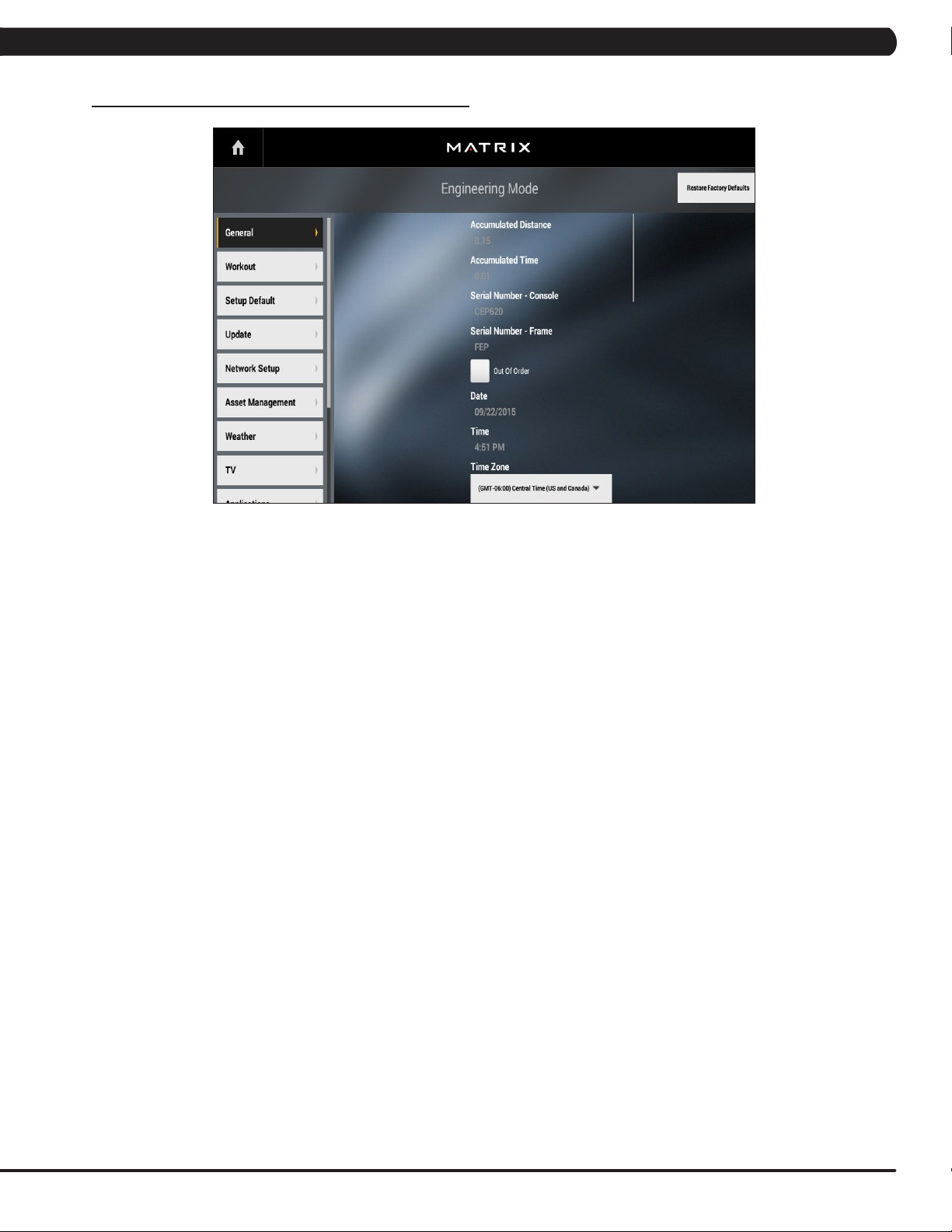
6.1 USING ENGINEERING MODE
CHAPTER 6: ENGINEERING MODE
1) To enter Engineering Mode, press "ENTER, 2, 0, 0, 1, ENTER" on the number keypad and Manager Mode will appear on the display.
2) Engineering Mode is divided into 9 tabs, located on the left side of the screen. They are General, Workout, Setup Defaults, Update,
Network Setup, Asset Management, Weather, TV, Applications, Calibration, Hardware, Service and Errors.
3) Choose a tab by touching the screen over the desired tab.
4) Each of the tabs has options that will appear once you have chosen that particular tab.
5) Press the "HOME" button or the EMERGENCY STOP to exit Engineering Mode.
19
Page 22
CHAPTER 6: ENGINEERING MODE
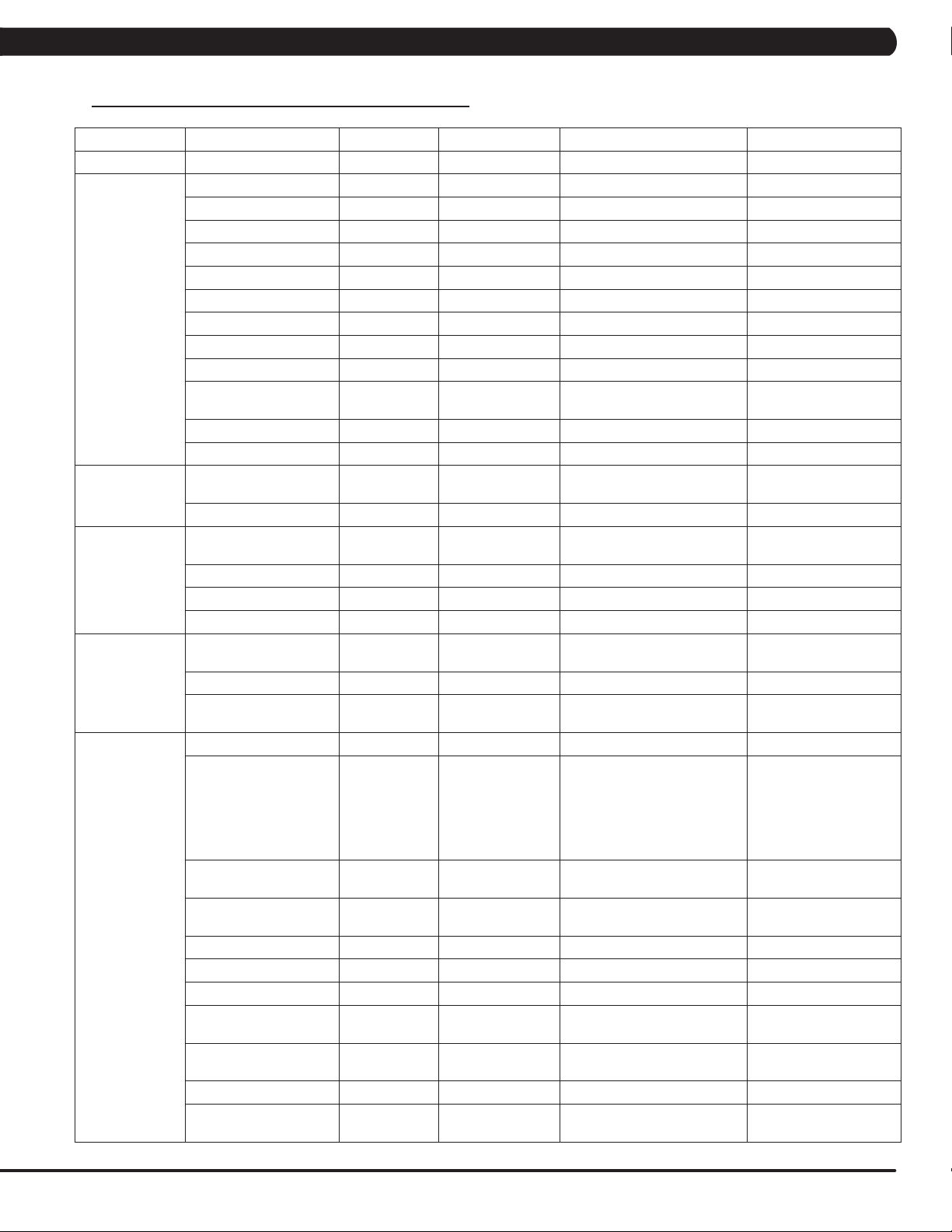
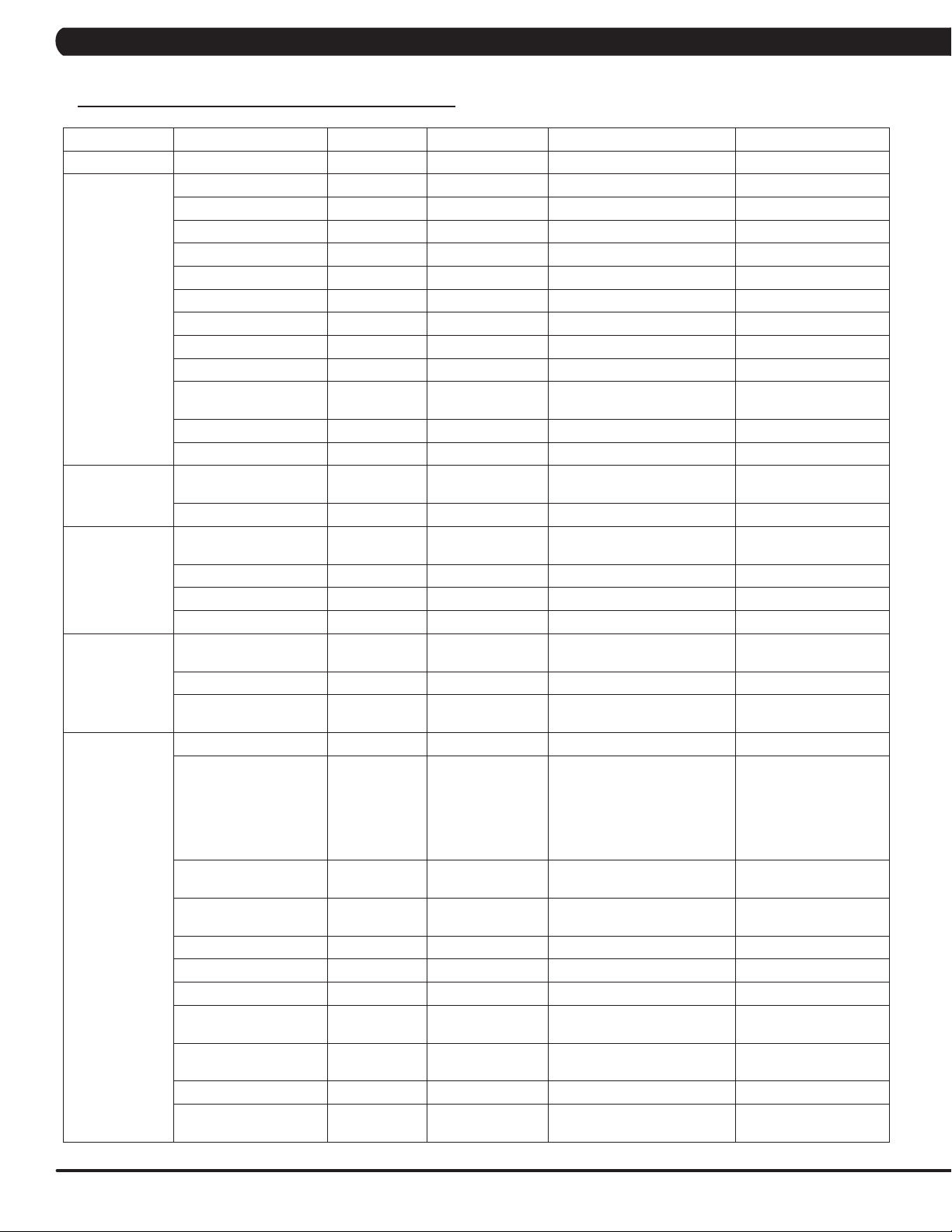
6.2 ENGINEERING MODE OVERVIEW
Category Name Models Default Range Units
Accumulated Time TACSEHUR 0 - Hours
(TAEHU) Miles/Km
(CS) Floors
-
MPH/KPH
Miles/Km
Feet
General
Workouts
Accumulated Distance TACSEHUR 0 -
Serial Number - Console TACSEHUR
Serial Number - Frame TACSEHUR
Demo mode TACSEHUR Check Yes/No
Out of order TACSEHUR Check Yes/No
Date TACSEHUR RTC Date
Time TACSEHUR RTC Time 00-23:00-59:00-59 12hr/24hr
Time Zone TACSEHUR Central Time - -
Time Format TACSEHUR 12 Hour 12 Hour, 24 Hour -
Screen Timeout TACSEHUR 30 15-120, Never Seconds
Software Version History TACSEHUR - - -
Firmware Versions TACSEHUR - - -
Show Setup Wizard TACSEHUR Check Yes/No
Language Setup TACSEHUR English (U.S.) See Languages Table -
Social Network Post TACSEHUR
Dapi Environment TACSEHUR Production - -
Keyboard Disable
Threshold
Maximum Workout Time TACSEHUR 60 10-120 Minutes
Maximum Workout
Calories
Maximum Workout
Distance
Maximum Workout Floors CS 200 Floors 15-200 Floors Floors -
Maximum Level C 20 10-25 -
E-Stop Enable C TRUE True/False -
E-Stop Sensitivity C 100 4-400 -
Pause Time TACSEHUR 5 1-10 Minutes
Maximum Speed T 12 3.1-15.0 MPH/KPH
Start Speed T 0.5 0.5-1.4 MPH/KPH
Maximum Incline TA (T)15/(A)100 (T)1.0-15.0/(A)1-100 (T)% Grade/(A)%
Elevation TA
Tread Sense Timeout T Disable 30, 60, 90, Disable -
Cooldown Time TACSEHUR 5 1-20 Minutes
Maximum Cool Down
Adjustment Time
T 2.0MPH/3.2KPH
TACSEHUR 10000 50-10000 Calories
TAEHUR 31.1Mile/50Km
TACSEHUR 5 1-20 Minutes
Prefix+(Type)
+YYMM00000
Prefix+(Type)
+YYMM00000
“I just exercised for
[time] on a Matrix
Fitness 7xi”
(T) Below 5000 eet
(A) 0
YYMMxxxxx -
YYMMxxxxx -
2000-2099/01
-12/01-31
- -
Machine Minimum -
4.0MPH/6.4KPH
(T)0.6-61.5Mile/1-99Km
(AEHUR) 0.6-31.1Mile/1-50Km
(T) Above/Below
(A) 0-10000
20
Page 23

CHAPTER 6: ENGINEERING MODE
6.2 ENGINEERING MODE OVERVIEW - CONTINUED
Category Name Models Default Range Units
Level TASEHUR 1 (TSEHUR)1-20 (A)1-25 -
Age TACSEHUR 30 10-99 Years
(THUR)50-400lbs/22-182kg
(AE)44-440lbs/20-200kg
(CS) 80-400lbs/36-182kg
- -
Setup Default
Weight TACSEHUR 150lbs/68kg
Height TC 70in/173cm 40-90in/101-228cm in/cm
Gender TACSEHUR Male Male/Female -
Default Workout Time TACSEHUR 30 5-Max Minutes
Default Workout Calories TACSEHUR 300 50-Max Calories
Default Workout Distance TAEHUR 3.1Mile/5.0Km 0.1-Max (Mile and Km) Miles/Km
Default Workout Floors CS 20 15-Max Floors
Default Workout Incline A 0 0-Max %
Default Web page TACSEHUR
Automatic Update TACSEHUR Check Check/No Check -
http://www.google.
com
lbs/kg
Update
Network Setup
Asset
Management
Update From USB TACSEHUR Update From USB Update From USB/Install -
Check For Updates TACSEHUR - Check For Updates/Install -
Wifi Mac Address TACSEHUR - - -
Ethernet Mac Address TACSEHUR - - -
Wi-fi Setup TACSEHUR - - -
Ethernet Setup TACSEHUR - - -
Facility ID TACSEHUR 0 0-10000 -
C(for Console)
+ Prefix(Type)
Serial Number - Console TACSEHUR
Serial Number - Frame TACSEHUR
Asset Management TACSEHUR No Yes/No
Workout Tracking TACSEHUR No Yes/No
RFID Module Installed TACSEHUR No Yes/No
Upload Custom Theme TACSEHUR - - -
Show Custom logo TACSEHUR No Yes/No -
Custom Welcome Screen TACSEHUR No Yes/No -
Custom Background
color
Show workout
Background
TACSEHUR No Yes/No -
TACSEHUR Production Dev, QA, Staging, Production -
+ Derivative
Model(A-Z,
AA, etc.)
+YYMMXXXXX
F (for Frame) +
Prefix (Type)+
Derivative Model
(A-Z, AA,etc.) +
YYMMXXXXX
- -
- -
21
Page 24
CHAPTER 6: ENGINEERING MODE
6.2 ENGINEERING MODE OVERVIEW - CONTINUED
Category Name Models Default Range Units
Weather Enable Alerts TACSEHUR Check Check/No Check -
Tuner Type TACSEHUR Main Main, Brazil, Japan -
Connection Type TACSEHUR Antenna Antenna/Cable -
Country TACSEHUR United States - Countries
Source TACSEHUR ATSC ATSC, QAM, Analog -
Start Channel TACSEHUR 2 0-1000 -
Default Channel TACSEHUR 3 1.00-1000.00 Channels
TV (Coaxial)
TV (Coaxial
Japan)
IPTV (Without
Set Top Box)
IPTV (With Set
Top Box)
Show TV Channel List TACSEHUR No Yes/No -
Aspect Ratio Mode TACSEHUR Auto Auto/Fill -
Over Scan Size TACSEHUR 0 0-20 -
Channel Button Setup TACSEHUR
Channel Order TACSEHUR - - -
Stop Channel TACSEHUR 100 0-1000 -
TV Channel Setup
(Control)
Default Channel TACSEHUR 3 1.00-1000.00 Channels
IPTV Channel Setup TACSEHUR
Over Scan Size TACSEHUR 0 0-20 -
Default Channel TACSEHUR 3 - Channels
Use SAP Channel TACSEHUR No Check Check/No Check -
IPTV HDMI Show
Remote
Over Scan Size TACSEHUR 0 0-20 -
IPTV Set Top Box Setup TACSEHUR None
Over Scan Size TACSEHUR 0 0-20 -
TACSEHUR -
TACSEHUR No Yes/No -
None/Channel 3 +
‘Name’ + TV Icon
None/Channel 1 +
‘Name’
Channel Number: 1-999 -
Up, Down, Left, Right,
Confirm, Scan, Menu, Exit
Source, Name, Icon IP Address
Enseo-3300_RAW IBT-
1283VOD LG_STB-2000_RAW
View input on mini
screen.
-
22
IPTV (HDMI over
IP)
IPTV Set Top Box Setup TACSEHUR None
IPTV HDMI over IP
Setup
IPTV HDMI over IP
Setup
Direct Connect TACSEHUR No Yes/No -
Enable ErP TACSEHUR No Yes/No -
Enable SSL TACSEHUR Ye s Yes/No -
IPTV HDMI Show
Remote
Enable Predefined
Commands
IPTV HDMI Bitrate TACSEHUR 4M 4M, 6M, 8M, 10M, 12M Mbps
HDMI over IP Command
List Setup
TACSEHUR Broadcast Broadcast -
TACSEHUR Connect Connect -
TACSEHUR No Yes/No -
TACSEHUR No Yes/No -
TACSEHUR - - -
Enseo-3300_RAW IBT-
1283VOD LG_STB-2000_RAW
-
Page 25
CHAPTER 6: ENGINEERING MODE
6.2 ENGINEERING MODE OVERVIEW - CONTINUED
Category Name Models Default Range Units
Default TV Channel TACSEHUR 3 - Channels
CAB
TV(Pro:ldiom)
Applications Application Setup TACSEHUR Show
Calibration
Hardware
TV Channel Setup TACSEHUR - Up, Down, Confirm
Default TV Channel TACSEHUR 3 - Channels
Tuner Type TACSEHUR CVBS HDMI / CVBS -
Key test TACSEHUR - - -
Calibration TA Calibrate Calibrate -
Run machine TACSEHUR - - -
RFID Module Installed TACSEHUR No Check Check/No Check -
Backlight Brightness TACSEHUR 40 0-100 -
Master Volume TACSEHUR 30 0-30 -
Headphone Insertions TACSEHUR 0 - -
Headphone Removals TACSEHUR 0 - -
ErP TACSEHUR Check Check/No Check -
ErP Timeout TACSEHUR 30 1-60 Minutes
Play Key Sound TACSEHUR Check Check/No Check -
Play Workout Countdown
Sound
Ignore Incline Error TACSEHUR Check Check/No Check -
TACSEHUR Check Check/No Check -
Move, Hide/Make Inactive,
Locked
View input on mini
screen.
-
Ignore B Level Error TACSEHUR Check Check/No Check -
LCM Test TACSEHUR Write Test Pattern - -
LCM Version TACSEHUR - - -
Small LCD Reversed TACSEHUR No Yes/No -
Default Command
Expired Seconds
CSAFE - - - -
Remote TV Default
Channel
Service Service History TACSEHUR - - -
Errors Error Code History TACSEHUR - - -
TACSEHUR 5 3-15 Seconds
- Disable Disable/Enable -
23
Page 26
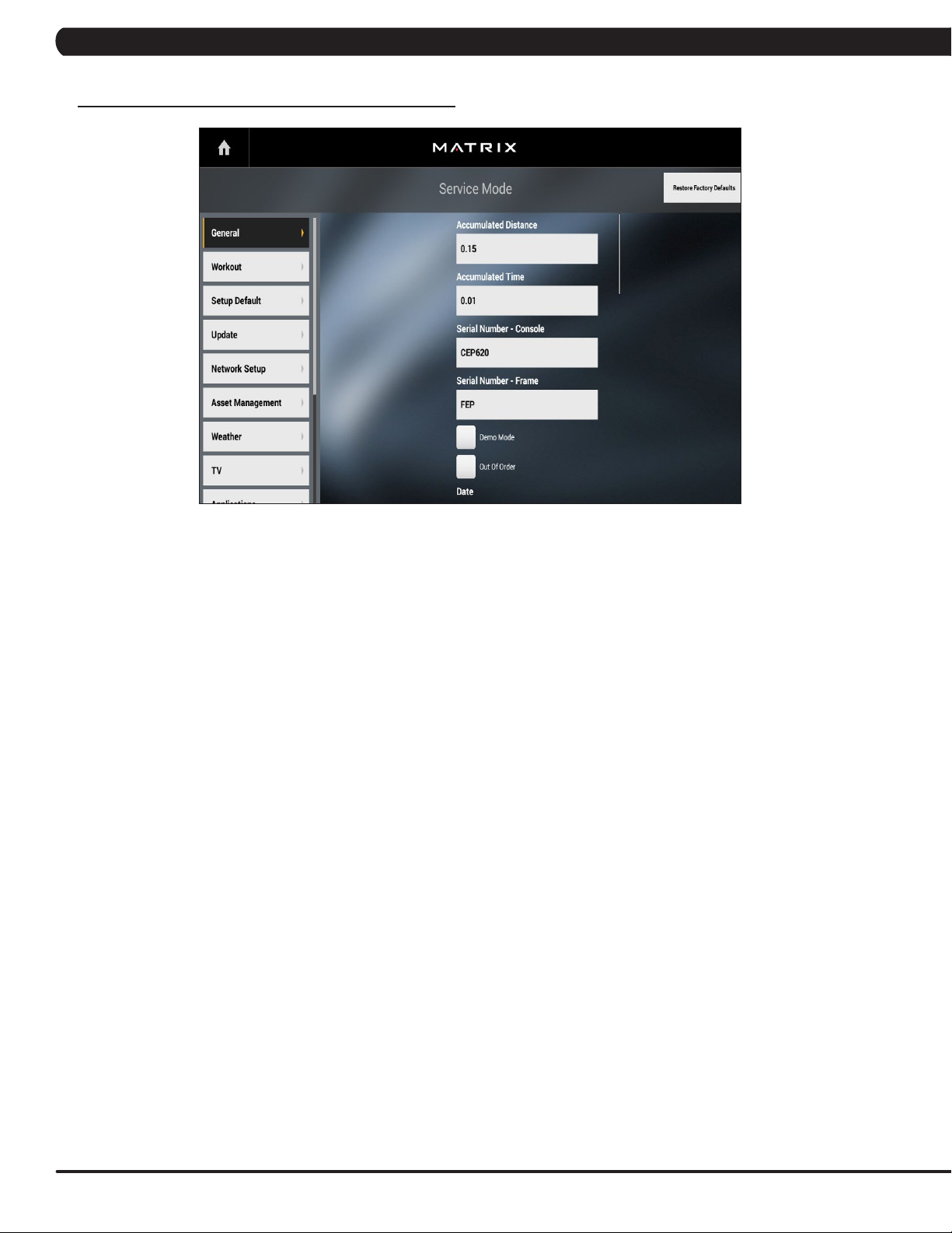
7.1 USING SERVICE MODE
CHAPTER 7: SERVICE MODE
1) To enter Service Mode, press "ENTER, 3, 0, 0, 1, ENTER" on the number keypad and Service Mode will appear on the display.
2) Service Mode is divided into 9 tabs, located on the left side of the screen. They are General, Workout, Setup Defaults, Network Setup,
Asset Management, Weather, TV, Applications, Hardware and Service.
3) Choose a tab by touching the screen over the desired tab.
4) Each of the tabs has options that will appear once you have chosen that particular tab.
5) Press the "HOME" button or the EMERGENCY STOP to exit Service Mode.
24
Page 27

CHAPTER 7: SERVICE MODE
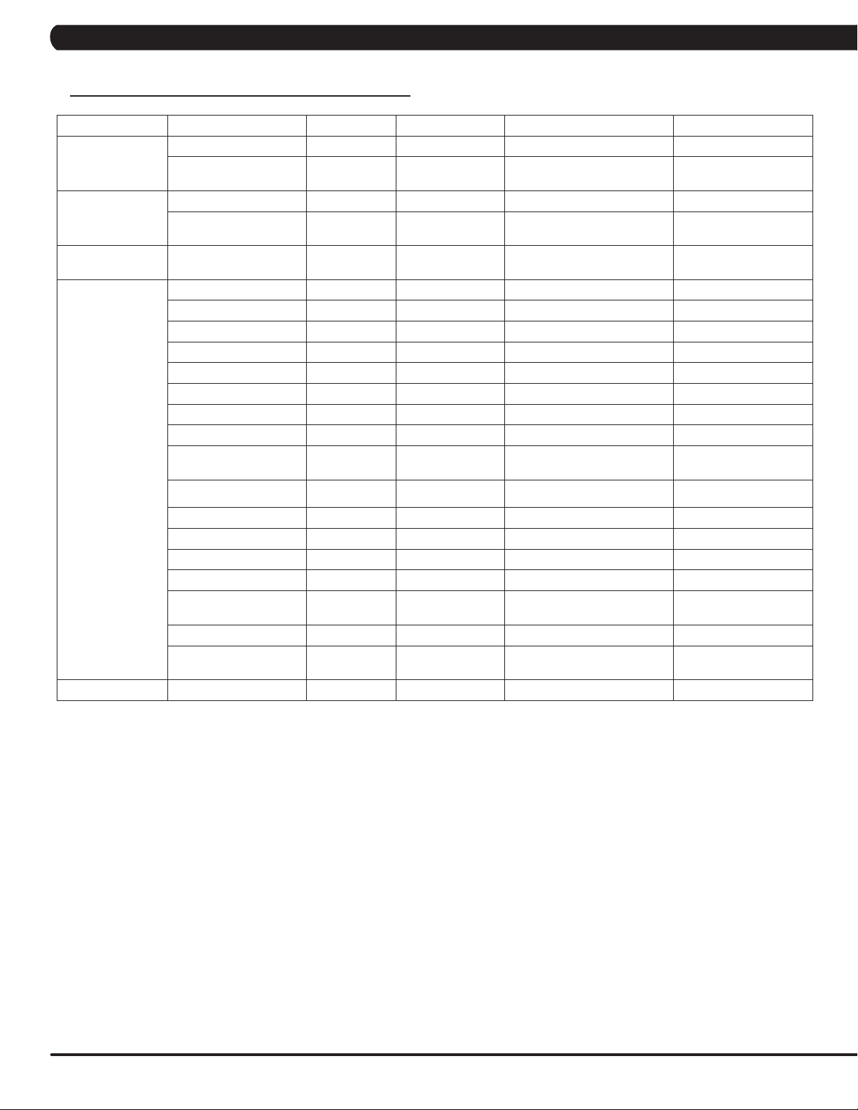
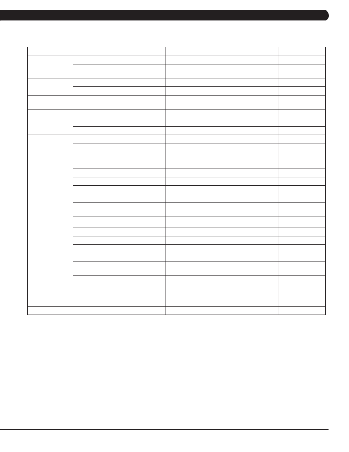
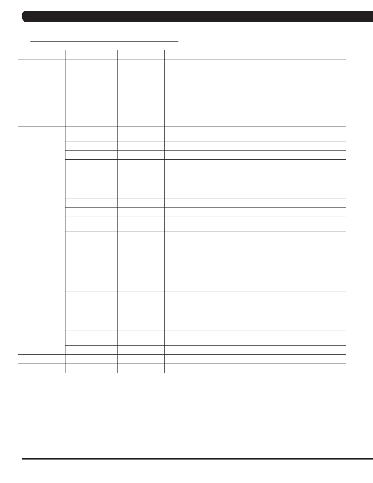
7.2 SERVICE MODE OVERVIEW
Category Name Models Default Range Units
Screen Timeout TACSEHUR 30 15-120, Never Seconds
Accumulated Time TACSEHUR 0 - Hours
General
Accumulated
Distance
Serial Number -
Console
Serial Number -
Frame
Date TACSEHUR RTC Date
Out of Order TACSEHUR No Yes/No -
Demo Mode TACSEHUR No Yes/No -
Time TACSEHUR RTC Time 00-23:00-59:00-59 12hr/24hr
Time Format TACSEHUR 12 Hour 12 Hour, 24 Hour -
Time Zone TACSEHUR Central Time - -
Software Version
History
Firmware Versions TACSEHUR - - -
Show Setup Wizard TACSEHUR No Yes/No -
Language Setup TACSEHUR English (U.S.) See Languages Table -
TACSEHUR 0 -
TACSEHUR
TACSEHUR
TACSEHUR - - -
Prefix+(Type)
+YYMM00000
Prefix+(Type)
+YYMM00000
YYMMxxxxx -
YYMMxxxxx -
2000-2099/01
-12/01-31
(TAEHU)Miles/Km
(CS)Floors
-
Workouts
Social Network Post TACSEHUR
Keyboard Disable
Threshold
Maximum Workout
Time
Maximum Workout
Calories
Maximum Workout
Distance
Maximum Workout
Floors
Maximum Level C 20 10-25 -
E-Stop Enable C TRUE True/False -
E-Stop Sensitivity C 100 4-400 -
Pause Time TACSEHUR 5 1-10 Minutes
Maximum Speed T 12 3.1-15.0 MPH/KPH
Start Speed T 0.5 0.5-1.4 MPH/KPH
Maximum Incline TA (T)15 / (A)100 (T)1.0-15.0/(A)1-100 (T)% Grade/(A)%
Elevation TA
Minimum Cooldown
Time
Maximum Cooldown
Time
Maximum Cool Down
Adjustment Time
T 2.0MPH/3.2KPH
TACSEHUR 60 10-120 Minutes
TACSEHUR 10000 50-10000 Calories
TAEHUR 31.1Mile/50Km
CS 200 Floors 15-200 Floors Floors -
TACSEHUR 2 1-5 Minutes
TACSEHUR 5 5-10 Minutes
TACSEHUR 5 1-20 Minutes
“I just exercised for
[time] on a Matrix
Fitness 7xi”
(T)Below 5000 Feet
(A) 0
- -
Machine Minimum -
4.0MPH/6.4KPH
(T) 0.6-61.5Mile/1-99Km
(AEHUR) 0.6-31.1Mile/1-
50Km
(T) Above/Below
(A) 0-10000
MPH/KPH
Miles/Km
Feet
25
Page 28

CHAPTER 7: SERVICE MODE
7.2 SERVICE MODE OVERVIEW - CONTINUED
Category Name Models Default Range Units
Level TASEHUR 1 (TSEHUR) 1-20 (A)1-25 -
Age TACSEHUR 30 10-99 Years
Weight TACSEHUR 150lbs/68kg
Height C 70in/173cm 40-90in/101-228cm in/cm
Gender TACSEHUR Male Male/Female -
Default Workout Time TACSEHUR 30 5-Max Minutes
(THUR) 50-400lbs/22-182kg
(AE) 44-440lbs/20-200kg
(CS) 80-400lbs/36-182kg
lbs/kg
Setup Default
Update
Network Setup
Default Workout Calories TACSEHUR 300 50-Max Calories
Default Workout Distance TAEHUR 3.1Mile/5.0Km 0.1-Max (Mile and Km) Miles/Km
Default Workout Floors CS 20 15-Max Floors
Default Workout Incline A 0 0-Max %
Default Web page TACSEHUR http://www.google.com - -
Automatic Update TACSEHUR Check Check/No Check -
Update From USB TACSEHUR Update From USB Update From USB/Install -
Check For Updates TACSEHUR Check For Updates Check For Updates/Install -
Wifi Mac Address TACSEHUR
Ethernet Mac Address TACSEHUR - - -
Wi-fi Setup TACSEHUR - - -
Ethernet Setup TACSEHUR - - -
Proxy Setup TACSEHUR - - -
-
- -
26
Asset
Management
Facility ID TACSEHUR 0 0-10000 -
C(for Console)
Serial Number - Console TACSEHUR
Serial Number - Frame TACSEHUR
Asset Management TACSEHUR - - -
Workout Tracking TACSEHUR - - -
RFID Module Installed TACSEHUR - - -
Upload Custom Theme TACSEHUR -
+ Prefix(Type)
+ Derivative
Model(A-Z, AA, etc.)
+YYMMXXXXX
F (for Frame) + Prefix
(Type)+ Derivative
Model (A-Z, AA,etc.) +
YYMMXXXXX
- -
- -
Theme: welcome, workout,
logo, color.
jpg, png, gif, jpeg, webp
Page 29
CHAPTER 7: SERVICE MODE
7.2 SERVICE MODE OVERVIEW - CONTINUED
Category Name Models Default Range Units
Weather Enable Alerts TACSEHUR Check Check/No Check -
Tuner Type TACSEHUR Main Main, Brazil, Japan -
Connection Type TACSEHUR Antenna Antenna/Cable -
Location TACSEHUR United States - Countries
Source TACSEHUR ATSC ATSC, QAM, Analog -
Start Channel TACSEHUR 2 0-1000 -
Default Channel TACSEHUR 3 1.00-1000.00 Channels
TV (Coaxial)
IPTV (Without
Set Top Box)
IPTV (With Set
Top Box)
IPTV (HDMI over
IP)
CAB
Show TV Channel
List
Aspect Ratio Mode TACSEHUR Auto Auto/Fill -
Over Scan Size TACSEHUR 0 0-20 -
Channel Button
Setup
Channel Order TACSEHUR - - -
Stop Channel TACSEHUR 100 0-1000 -
IPTV Channel Setup TACSEHUR
Over Scan Size TACSEHUR 0 0-20 -
Default Channel TACSEHUR 3 - Channels
Use SAP Channel TACSEHUR No Check Check/No Check -
IPTV HDMI Show
Remote
Over Scan Size TACSEHUR 0 0-20 -
IPTV Set Top Box
Setup
Over Scan Size TACSEHUR 0 0-20 -
IPTV Set Top Box
Setup
IPTV HDMI over IP
Setup
IPTV HDMI over IP
Setup
Direct Connect TACSEHUR No Yes/No -
Enable ErP TACSEHUR No Yes/No -
Enable SSL TACSEHUR Ye s Yes/No -
IPTV HDMI Show
Remote
Enable Predefined
Commands
IPTV HDMI Bitrate TACSEHUR 4M 4M, 6M, 8M, 10M, 12M Mbps
HDMI over IP
Command List Setup
Default TV Channel TACSEHUR 3 - Channels
TV Channel Setup TACSEHUR - Up, Down, Confirm
TACSEHUR No Yes/No -
TACSEHUR
TACSEHUR No Yes/No -
TACSEHUR None
TACSEHUR None
TACSEHUR Broadcast Broadcast -
TACSEHUR Connect Connect -
TACSEHUR No Yes/No -
TACSEHUR No Yes/No -
TACSEHUR - Export, Import, Add
None/Channel 3 +
‘Name’ + TV Icon
None/Channel 1 +
‘Name’
Channel Number: 1-999 -
Source, Name, Icon IP Address
Enseo-3300_RAW IBT-
1283VOD LG_STB-2000_
RAW
Enseo-3300_RAW IBT-
1283VOD LG_STB-2000_
RAW
Predefined Commands
(can export/import XML
View input on mini
-
-
file)
screen.
27
Page 30
CHAPTER 7: SERVICE MODE
7.2 SERVICE MODE OVERVIEW - CONTINUED
Category Name Models Default Range Units
Default TV Channel TACSEHUR 3 - Channels
TV(Pro:ldiom)
Applications Application Setup TACSEHUR Show - -
Calibration
Hardware
Management
Service Service History TACSEHUR - -
Errors Error Code History TACSEHUR
Tuner Type TACSEHUR CVBS HDMI/CVBS
Key test TACSEHUR
Calibration TA Calibrate Calibrate
Run machine TACSEHUR
RFID Module
Installed
Backlight Brightness TACSEHUR 40 0-100 -
Master Volume TACSEHUR 30 0-30 -
Headphone
Insertions
Headphone
Removals
ErP TACSEHUR Check Check/No Check -
ErP Timeout TACSEHUR 30 1-60 Minutes
Play Key Sound TACSEHUR Check Check/No Check -
Play Workout
Countdown Sound
Ignore Incline Error TACSEHUR Check Check/No Check -
Ignore B Level Error TACSEHUR Check Check/No Check -
LCM Test TACSEHUR Write Test Pattern - -
LCM Version TACSEHUR - - -
Small LCD Reversed TACSEHUR No Yes/No -
Default Command
Expired Seconds
CSAFE - - - -
Remote TV Default
Channel
Import Settings From
USB
Export Settings From
USB.
Export Settings TACSEHUR Broadcast Broadcast/Receive -
TACSEHUR No Check Check/No Check -
TACSEHUR 0 - -
TACSEHUR 0 - -
TACSEHUR Check Check/No Check -
TACSEHUR 5 3-15 Seconds
- Disable Disable/Enable -
TACSEHUR - - -
TACSEHUR Broadcast Broadcast/Receive -
- - -
- -
- - -
-
-
-
-
28
Page 31
CHAPTER 8: TROUBLESHOOTING
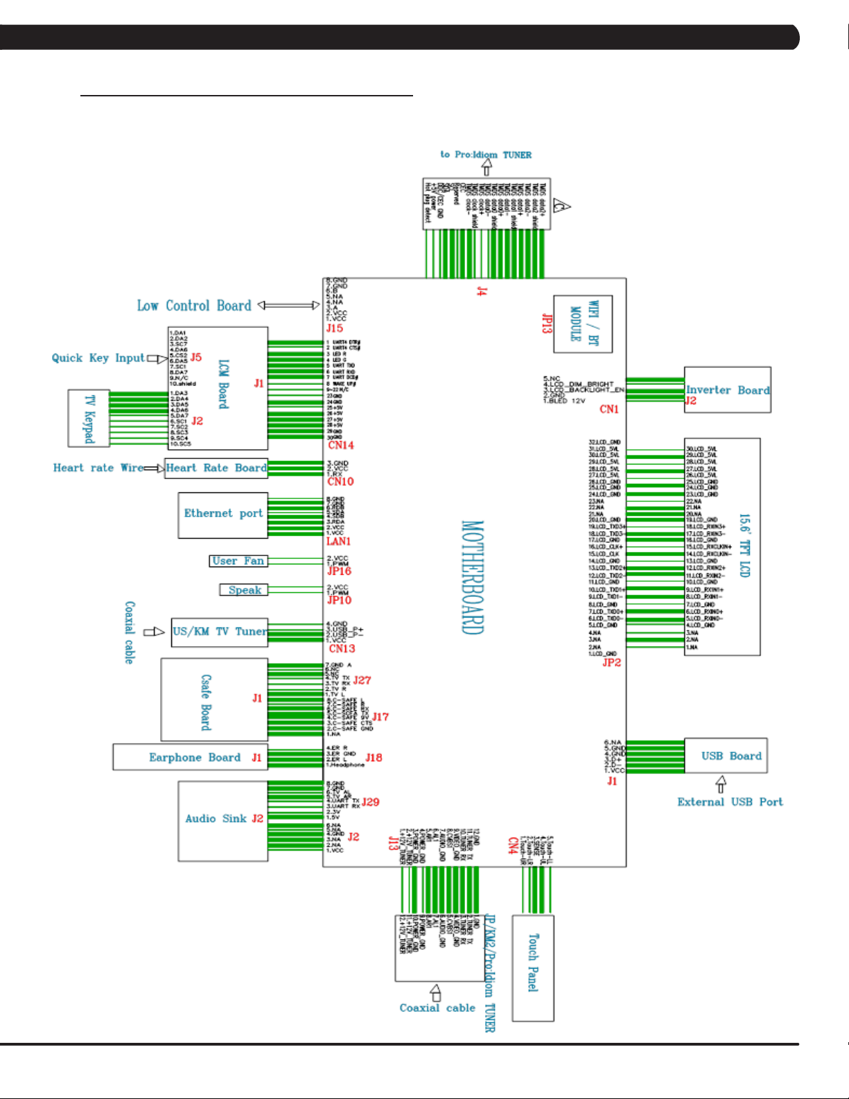
8.1 ELECTRICAL DIAGRAMS
ELECTRICAL BLOCK DIAGRAMS: HURESAC-7XE-05-C
29
Page 32

CHAPTER 8: TROUBLESHOOTING
8.1 ELECTRICAL DIAGRAMS - CONTINUED
ELECTRICAL BLOCK DIAGRAMS: T-7XE-05-C
30
Page 33

CHAPTER 8: TROUBLESHOOTING
8.1 ELECTRICAL DIAGRAMS
ELECTRICAL BLOCK DIAGRAMS: HURESAC-7XI-03-C
31
Page 34

CHAPTER 8: TROUBLESHOOTING
8.1 ELECTRICAL DIAGRAMS - CONTINUED
ELECTRICAL BLOCK DIAGRAMS: T-7XI-03-C
32
Page 35

CHAPTER 8: TROUBLESHOOTING
8.1 ELECTRICAL DIAGRAMS - CONTINUED
TV KEY CONNECT WIRE
LCM CONNECT WIRE
33
Page 36

CHAPTER 8: TROUBLESHOOTING
8.1 ELECTRICAL DIAGRAMS - CONTINUED
HEART RATE CONNECT WIRE
HANDS CONNECT WIRE
34
INVERTER WIRE
Page 37

CHAPTER 8: TROUBLESHOOTING
8.1 ELECTRICAL DIAGRAMS - CONTINUED
DIGITAL COMMUNICATION WIRE
ENTERTAINMENT KEYPAD
35
Page 38

CHAPTER 8: TROUBLESHOOTING
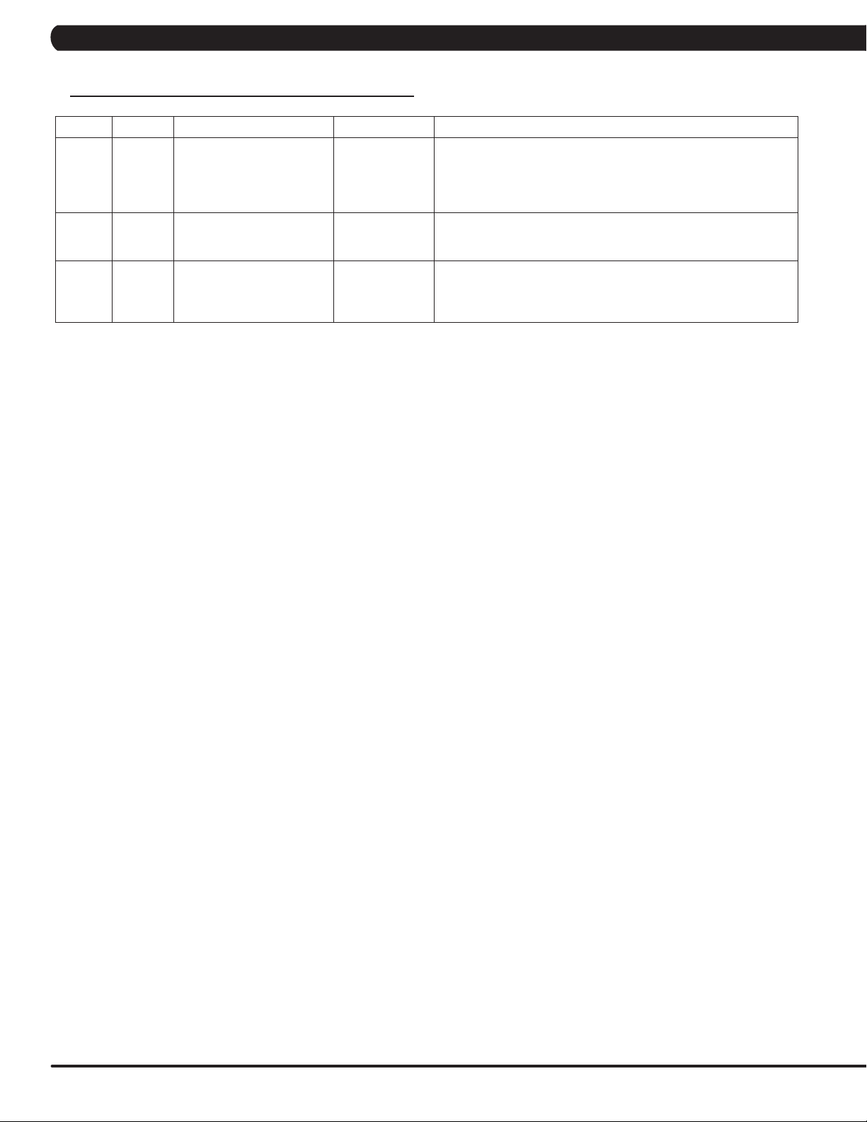
8.2 ERROR CODE LIST
CODE CLASS DESCRIPTION MACHINE SOLUTION
a. It occurs when the calibration time is too long or the calibration distance is too
short.
01A1 C Incline calibration error A
01A3 C Motor is disconnected T
01A8 C Main motor over current T
01AC C
01AF C
01B4 C
014A
(01AE)
0140 B Incline motor operation fail A
0141 B Motor over temperature T
0144 B Motor over current T
Electro magnet (ECB) over
current
Electro magnet (ECB) disconnected
Resistance disconnect A
Electro magnet (ECB) disconnected
Battery connection reverse
protection
LCB charge current is
B
abnormal
HUR
C
HUR
C
AHUR
AHUR
b. Don’t fix the incline motor tube then turn on the power.
- If the console still shows 01A1, please replace incline motor.
- If auto calibration is finished, please follow the incline motor installation
SOP to fix incline motor.
c. Replace LCB.
a. Check the connection of the motor cable at the MCB.
b. Check if the MCB LED DSP1 (MCU).
- If LED DSP1 is blinking or solid light, replace the motor
- If LED DSP1 is not lit, replace the MCB.
a. Check the condition of the running deck and belt. Replace the belt and flip or
replace the running deck as needed.
b. Replace the MCB.
a. Check if the Electro-magnet is short circuited or open.
b. If the resistance data shows a short/open ohms or is outside the range of 12.8
~14.2 ohms, replace the Electro-magnet.
c. If the resistance data is in the range between 12.8 ~14.2 ohms, replace the LCB.
a. On standby mode, measure the resistance on ECB1 and ECB2. Please check the
ECB extension cable connection at the LCB (pins 1 & 3 for ECB1, pins 2 & 4 for
ECB2), there should be between 12.8 ~ 14.2 ohms.
- If the ECB resistance is out of the range, replace the ECB.
- If the ECB resistance is within the range, replace the LCB.
b. Check the gap of ECB1 and ECB2. There should be a gap of .5mm between the
ECB and the flywheel.
a. Check if the Electro-magnet is short circuited or open.
b. If the resistance data shows a short/open ohms or is outside the range of 12.8
~14.2 ohms, replace the Electro-magnet.
c. If the resistance data is in the range between 12.8 ~14.2 ohms, replace the LCB.
a. Check if the resistance is short circuit.
- If resistance data is under 10 ohms, please replace power resistance.
- If resistance data is over 10 ohms, please replace LCB.
a. Check the connection of the ECB extension cable from the LCB to the ECB.
b. Check to see if LED8 and LED10 on the LCB have a brief light for 3 second when
you power on machine.
- If LED8 and LED10 do not have a brief light, replace the LCB.
- If LED8 and LED10 do have a brief light, check the ECB extension cable
connection at the LCB (pins 1 & 3 for ECB1, pins 2 & 4 for ECB2), there
should be between 12.8 ~ 14.2 ohms.
- If the ECB resistance is out of the range, replace the ECB.
- If the ECB resistance is within the range, replace the LCB.
a. Check the battery wire connection between the battery and LCB.
b. Check the battery voltage.
- If there is no data on voltage, replace the battery.
- If there is data on voltage, replace the LCB.
a. Replace LCB.
a. Please run Auto Calibration.
b. If the error code happens in Auto-calibration, the machine still can work, no need
to do anything.
c. If the error code happens in workout, please replace the incline motor.
a. Check the connection of the motor cable at the MCB.
b. Use a multi-meter to check the motor wire circuit. Set the multi-meter to Ohms
and place both terminals on the blue wires of the motor cable.
- If there is an Ohm reading above 0, replace the motor.
- If the Ohm reading is 0, replace the MCB.
a. Check the condition of the running deck and belt. Replace the belt and flip or
replace the running deck as needed.
b. Replace the MCB.
36
Page 39

CHAPTER 8: TROUBLESHOOTING
8.2 ERROR CODE LIST - CONTINUED
CODE CLASS DESCRIPTION MACHINE SOLUTION
a. Please check the incline motor wire connection between the incline
and LCB.
A
0147
(01A0)
0148
(01A7)
0149
(01AC)
02AB C Machine type error. ESHURA
02AD C MCB is over temperature T
02A0 C Encoder error C
02A2 C Over DC bus voltage T
02A3 C
02A7 C
02BA C
02BB C
02BC C
02BD C
02BE C DC brake error. C
02BF C DC brake Over Current C
B Incline motor disconnection
B Incline motor over current. A
The resistance current is
B
over
Low AC power input voltage
when motor running
over I rms of phase current
of motor
The inner memory IC data
read error.
Inverter hardware interrupts
error.
Ground connection or fuse
error
Drive hardware interrupt
error.
T
A
T
T
T
T
T
T
b. Please check the incline motor VR if there’s data.
- If there’s no data, replace the incline.
- If there’s data, replace the LCB.
a. Please check the incline motor wire connection between the incline
and MCB.
b. Run auto calibration.
c. If the issue is not solved by replacing the incline motor.
a. Don’t fix the incline motor tube then turn on the power.
- If the console still shows error, please replace incline motor.
- If the console does not show error, please follow the incline
motor installation SOP to fix incline motor.
b. Replace LCB.
a. Please check if the resistance is short circuit.
- If resistance data is under 10 ohms, please replace power
resistance.
- If resistance data is over 10 ohms, please replace LCB.
a. Change the machine type on the console to match the correct
frame.
a. Check if that both fans are operating (there is a fan mounted to the
MCB itself as well as an external fan). Also check the connection
of the fans at the MCB.
b. If the fans are running correctly, replace the MCB.
a. Check the connection of the speed sensor cable from the LCB to
the speed sensor.
b. Check to see if LED D35 on the LCB is on when the brake is
turned to the left release position.
c. If LED D35 is off, move the stairs about 3 stairs and check to see
if LED D35 is flashing.
- If not, replace the speed sensor.
- If yes, adjust the speed sensor position and clean the speed
sensor of any debris then re-test.
a. Please check if the input power is normal(110V : over 140V/ 220V:
over 280V)
b. Replace the MCB.
a. Please check if the input power is normal(110V : low 76V/ 220V:
low 186V)
b. Replace the MCB.
a. Please check the Motor wire connection between the Motor and
MCB.
b. Please use the electric meter to check the 3 points (U/V/W) and
see if there’s data of inside impedance.
- If yes, replace MCB.
- If no, replace Motor set.
a. Reboot power, if error shows again, replace the MCB.
b. Reboot power, if error shows again, replace the MCB.
a. Check the Motor wire (3 points U/V/W) and ground wire whether
short.
b. Replace the MCB.
a. Replace MCB.
a. Check the power extend wire connection between the brake and
LCB for any damage.
b. Check to see if the stairs will move when you are in the stop posi-
tion. If yes, replace the brake.
a. Check the power extend wire connection between the brake and
LCB for any damage.
b. Check to see if the stairs will move when you are in the stop posi-
tion. If yes, replace the brake.
37
Page 40

CHAPTER 8: TROUBLESHOOTING
8.2 ERROR CODE LIST - CONTINUED
CODE CLASS DESCRIPTION MACHINE SOLUTION
02B2 C Safe key action response T
02B4 C Resistance Type Error ESHURA
02B5 C
02B6 C Speed up have over current T
02B7 C Speed down is overcurrent T
02B8 C Running status is overcurrent T
02B9 C
02C0 C DC brake in manual mode C
02C1 C Speed tracking error C
02C2 C
02C3 C Frame IR sensor error C
02C4 C
02C5 C
02C6 C
02C7 C
0201 A LCB battery low voltage ESA a. Plug in the machine to charge battery for 24 hours.
0247 B LCB fail ESHURA a. Replace LCB.
0248 B
Inverter sensor the normal
rated current over 150% ,
can hold 60 sec
The inner memory IC data
write error
CZ 3IR sensors have no
communication or disconnected over 3 seconds
The frequency error form
control zone
The frequency error for frame
IR sensor
The receiver disconnection
for control zone
The receiver disconnection
for frame IR sensor
Battery disconnection or
fail ( LCB battery voltage is
less than 6 volts )
T
T
C
C
C
C
C
ESHURA
a. Check the connection of the safety key (emergency stop) switch. If the
switch is always open or shorted out, replace the switch.
b. If the emergency stop does not resolve the issue, replace the PCB.
a. Make sure machine type is set for the correct frame in console.
- If yes, replace LCB.
- If no, change to correct type and reboot the power.
a. Replace MCB.
a. Check the condition of the running deck and belt. Replace the belt and
flip or replace the running deck as needed.
b. Replace the MCB.
a. Check the condition of the running deck and belt. Replace the belt and
flip or replace the running deck as needed.
b. Replace the MCB.
a. Check the condition of the running deck and belt. Replace the belt and
flip or replace the running deck as needed.
b. Replace the MCB.
a. Reboot power, if error shows again, replace the MCB.
a. Check if the DC brake is in the “Right “lock position. Release the brake
(move to the left) if in lock position.
b. Replace the brake.
a. Adjust the speed sensor position and clean the speed sensor of any
debris.
b. Check the ECB extension cable connection at the LCB (pins 1 & 3
for ECB1, pins 2 & 4 for ECB2), there should be between 12.8 ~ 14.2
ohms, check which ECB is outside the range and replace it.
a. Check if there’s something blocking the control zone 3 IR sensors.
b. Check if the control zone 3IR sensors (transmitter and receiver) are
aligned.
c. Check the connection of the control zone extension cable from the
transmission board to the receiver board.
d. Replace the transmission board or control zone extension cable as
needed.
a. Check if there’s something blocking the frame IR sensors.
b. Check if the frame IR sensors (transmitter and receiver) are aligned.
c. Check the connection of the frame IR transmitter cable from the LCB
to the frame IR transmitter sensors.
d. Replace the frame IR transmitter cable if the cable is defective.
a. Replace the control zone transmission board or receiver board.
a. Replace LCB.
a. Check the connection of the control zone extension cable from the
LCB to the control zone.
b. Replace the receiver board.
a. Check the connection of the frame IR receiver cable from the LCB to
the frame IR receiver sensor.
b. Replace the frame IR receiver cable.
a. Check battery wire connection to LCB.
b. Check to see if the battery voltage is less than 6 volt.
- If less than 6 volt, replace battery.
- If not, replace LCB.
38
Page 41

CHAPTER 8: TROUBLESHOOTING
8.2 ERROR CODE LIST - CONTINUED
CODE CLASS DESCRIPTION MACHINE SOLUTION
03A5 C Failed to load program Console a. Replace UCB.
03A6 C Failed to run program Console a. Replace UCB.
03A8 C Machine type error ESHURACT
0301 A Memory block damage Console a. Enter the Engineer mode disable B Level Error, by pass CLASS
0302 A UCB low battery voltage Console a. Enter the Engineer mode disable B Level Error, by pass CLASS
0303 A UCB low supply voltage Console a. Enter the Engineer mode disable B Level Error, by pass CLASS
0304 A Earphone Board Need
0305 A USB Hardware OT or OC Console a. Enter the Engineer mode disable B Level Error, by pass CLASS
0306 A Keypad press keep 60 sec-
0340 B Key pad in extraordinary
0341 B Fan over current Console a. Enter the Engineer mode disable B Level Error, by pass CLASS
0343 B UCB Over supply voltage Console a. Enter the Engineer mode disable B Level Error, by pass CLASS
0345 B Correct packet but LCB with-
0346 B UCB detect the error of LCB
0347
(03A7)
0348
(03A9)
04A0 C
04B0 C
04B1 C
Replace
onds
operation
out the function
incline position error
B VA Load program fail Console a. Enter the Engineer mode disable B Level Error, by pass CLASS
B Motor not to run Console a. Enter the Engineer mode disable B Level Error, by pass CLASS
If LCB have no message to
return UCB over 3 seconds
UCB not have communication response
IO board not have communication response
Console a. Enter the Engineer mode disable B Level Error, by pass CLASS
Console a. Enter the Engineer mode disable B Level Error, by pass CLASS
Console a. Enter the Engineer mode disable B Level Error, by pass CLASS
Console a. Enter the Engineer mode disable B Level Error, by pass CLASS
Console a. Enter the Engineer mode disable B Level Error, by pass CLASS
Communication
Errors
Communication
Errors
Communication
Errors
a. Change the correct machine type in the console and reboot
power again.
A and B error code.
b. Replace UCB.
A and B error code.
b. Replace battery.
A and B error code.
b. Make sure the RPM over 35, when the machine of self-power
mode.
A and B error code.
b. Replace Earphone Board.
A and B error code.
b. Replace UCB.
A and B error code.
b. Replace Keypad.
A and B error code.
b. Replace Keypad.
A and B error code.
b. Replace Fan.
A and B error code.
b. Check the LCB provide power whether over 13 voltage
If yes, replace LCB.
If not, replace UCB.
A and B error code.
b. Replace UCB.
A and B error code.
b. Running the incline motor calibration again.
A and B error code.
b. Replace VA Micro SD card.
A and B error code.
b. Replace UCB.
a. Check the connection of the console cable at both ends and
perform continuity test.
b. Replace LCB.
a. Check the connection of the console cable at both ends and
perform continuity test.
b. Replace UCB.
a. Replace UCB.
39
Page 42
CHAPTER 8: TROUBLESHOOTING
8.2 ERROR CODE LIST - CONTINUED
CODE CLASS DESCRIPTION MACHINE SOLUTION
a. Enter the Engineer mode disable B Level Error, by pass CLASS
0440 B Timeout receive packet.
0441 B
0442 B
When UCB implements a
command, LCB has no this
command
The received command code
from the console is correct
and is supported, but it has
less or more data arguments
Communication
Errors
Communication
Errors
Communication
Errors
A and B error code.
b. Check the connection of the console cable at both ends and per-
form continuity test.
c. Replace LCB.
a. Enter the Engineer mode disable B Level Error, by pass CLASS
A and B error code.
a. Enter the Engineer mode disable B Level Error, by pass CLASS
A and B error code.
40
Page 43

CHAPTER 9: PART REPLACEMENT GUIDE
9.1 WORKING ENVIRONMENT SET UP FOR PARTS REPLACEMENT
1. The desk that the product contacts must have antistatic tablecloth or antistatic foam (Figure A).
FIGURE A
2. The working personnel needs to wear antistatic ring and the ring must be grounded(Figure B & C).
FIGURE CFIGURE B
41
Page 44

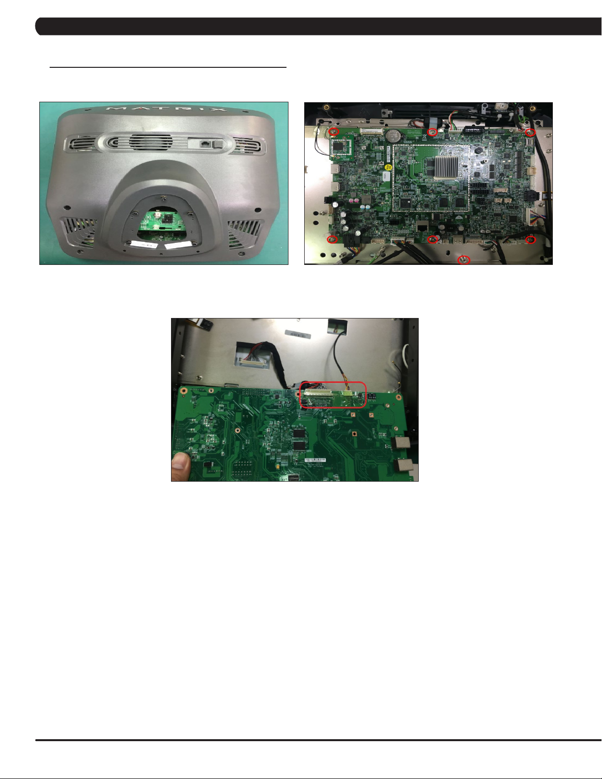
CHAPTER 9: PART REPLACEMENT GUIDE
9.2 T7XE UCB REPLACEMENT
1. Remove the 4 screws holding on the back cover (Figure A).
2. Remove the 4 screws holding on the console fan upper cover (Figure B).
3. Remove the 7 screws holding on the UCB (Figure C).
4. Unplug the LVDS and Inverter cable from UCB (Figure D).
FIGURE BFIGURE A
42
FIGURE DFIGURE C
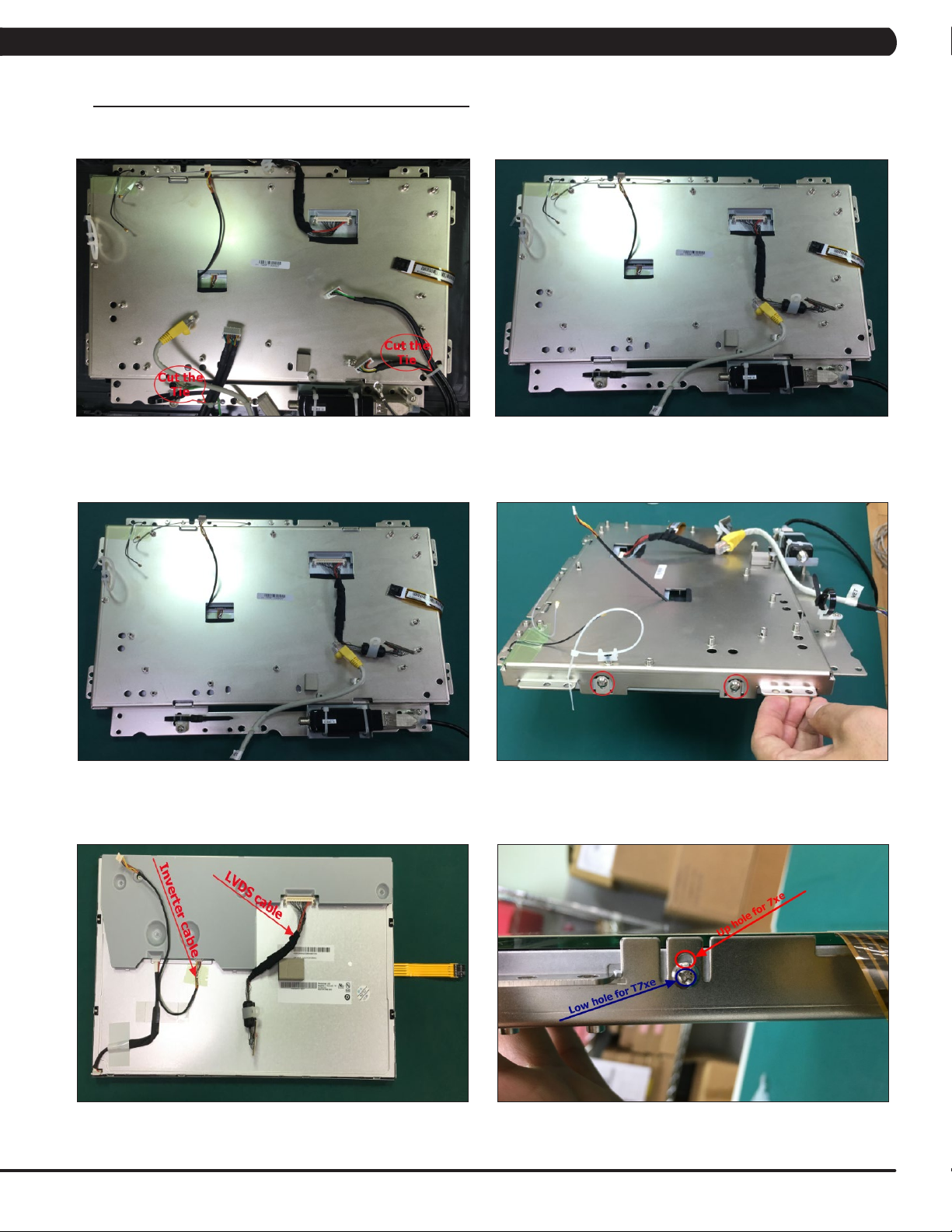
Page 45

CHAPTER 9: PART REPLACEMENT GUIDE
9.3 T7XE TFT-LCD MODULE REPLACEMENT
1. Remove the UCB as outlined in Section 9.2.
2. Remove the 12 screw holding on the Reinforce Set (Figure A).
3. Cut the two ties on the fixing plate (Figure B).
4. Remove the fixing plate set from console cover (Figure C).
5. Remove the 4 screw holding on the TFT- Panel (Figure D).
FIGURE BFIGURE A
FIGURE DFIGURE C
6. Unplug the Inverter cable and LVDS cable (Figure E).
7. Note : There are two holes on panel fixing plate, the upper hole is for 7xe and the lower hole is for T7xe (Figure F).
FIGURE FFIGURE E
43
Page 46
CHAPTER 9: PART REPLACEMENT GUIDE
9.4 7XE UCB REPLACEMENT
1. Remove the 6 screws holding on the back cover (Figure A).
2. Remove the 7 screws holding on the UCB (Figure B).
3. Unplug the LVDS and Inverter cable from UCB (Figure C).
FIGURE BFIGURE A
44
FIGURE C
Page 47
CHAPTER 9: PART REPLACEMENT GUIDE
9.5 7XE TFT-LCD MODULE REPLACEMENT
1. Remove the UCB as outlined in Section 9.4.
2. Cut the two ties on the fixing plate (Figure A).
3. Remove the fixing plate set from console cover (Figure C).
4. Remove the 4 screw holding on the TFT- PanelRemove the UCB (Figure D).
FIGURE BFIGURE A
FIGURE DFIGURE C
5. Unplug the Inverter cable and LVDS cable (Figure E).
6. Note : There are two holes on panel fixing plate, the upper hole is for 7xe and the lower hole is for T7xe (Figure F).
FIGURE FFIGURE E
45
Page 48

CHAPTER 9: PART REPLACEMENT GUIDE
9.6 T7XI UCB REPLACEMENT
1. Remove the 4 screws holding on the back cover (Figure A).
2. Remove the 4 screws holding on the console fan upper cover (Figure B).
3. Remove the 7 screws holding on the UCB (Figure C).
4. Unplug the LVDS and Inverter cable from UCB (Figure D).
FIGURE BFIGURE A
46
FIGURE DFIGURE C
Page 49

CHAPTER 9: PART REPLACEMENT GUIDE
9.7 T7XI TFT-LCD MODULE REPLACEMENT
1. Remove the UCB as outlined in Section 9.6.
2. Remove the 12 screw holding on the Reinforce Set (Figure A).
3. Cut the tie on the fixing plate (Figure B).
4. Lose the touch panel tie holding on the fixing plate (Figure C).
5. Remove the fixing plate set from console cover (Figure D).
FIGURE BFIGURE A
6. Remove the 4 screw holding on the TFT- Panel (Figure E).
7. Unplug the Inverter cable and LVDS cable (Figure F).
FIGURE DFIGURE C
FIGURE FFIGURE E
47
Page 50

CHAPTER 9: PART REPLACEMENT GUIDE
9.8 7XI UCB REPLACEMENT
1. Remove the 6 screws holding on the back cover (Figure A).
2. Remove the 7 screws holding on the UCB (Figure B).
3. Unplug the LVDS and Inverter cable from UCB (Figure C).
FIGURE BFIGURE A
48
FIGURE C
Page 51

CHAPTER 9: PART REPLACEMENT GUIDE
9.9 7XI TFT-LCD MODULE REPLACEMENT
1. Remove the UCB as outlined in Section 9.7.
2. Cut the tie and remove the Tuner set on the fixing plate (Figure A).
3. Lose the touch panel tie holding on the fixing plate (Figure B).
4. Remove the fixing plate set from console cover (Figure C).
5. Remove the 4 screw holding on the TFT- Panel (Figure D).
FIGURE BFIGURE A
6. Unplug the Inverter cable and LVDS cable (Figure E).
FIGURE DFIGURE C
FIGURE E
49
Page 52

CHAPTER 10: CONSOLE SPECIFICATIONS AND ASSEMBLY GUIDE
10.1 VA INSTALLATION
Model
T7xi / T7xe
7xi / 7xe
Note: If the console is installed with VA memory card, there will be VIRTUAL ACTIVE icon at home page (Figure A);
if the console is not installed with VA memory card, there will not be the icon (Figure B).
VA part number #
1000398928 or
1000356690
1000379202 or
1000356622
50
FIGURE BFIGURE A
Page 53
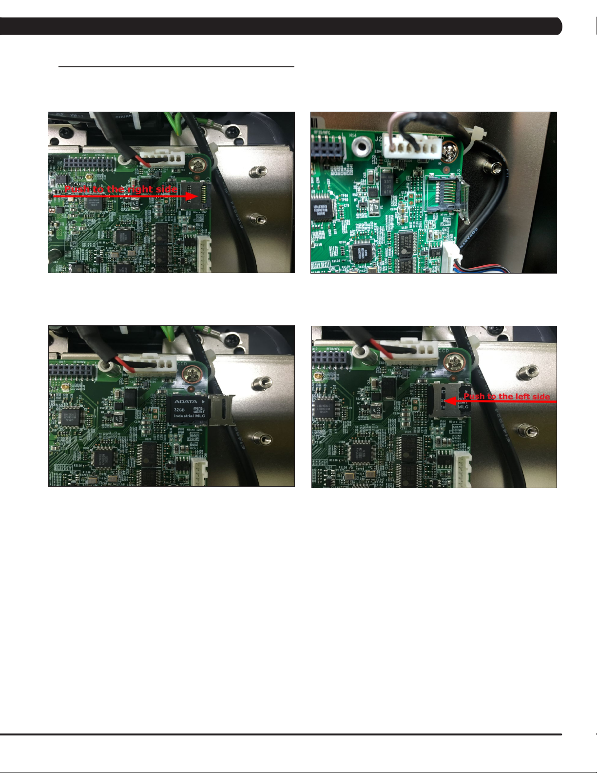
CHAPTER 10: CONSOLE SPECIFICATIONS AND ASSEMBLY GUIDE
10.1 VA INSTALLATION - CONTINUED
1. Remove the console back cover.
2. Gently slide the memory card door to the right side (Figure A) and the door will release (Figure B).
Important: Do not attempt to insert the memory card before releasing the door. Doing so could cause the door to break off.
FIGURE BFIGURE A
4. Put the VA memory card to the socket (Figure C).
5. Push back memory card socket to the left side to fix the memory card (Figure D).
FIGURE C
FIGURE D
51
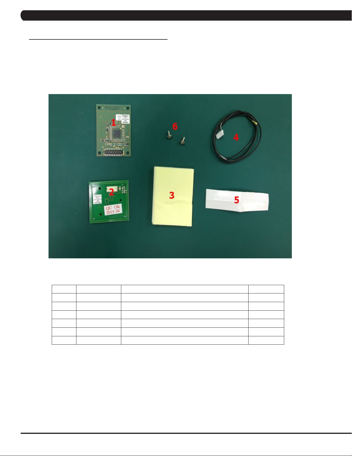
Page 54

CHAPTER 10: CONSOLE SPECIFICATIONS AND ASSEMBLY GUIDE
10.2 RFID INSTALLATION
1. T7XE / T7XI RFID INSTALLATION
MAIN COMPONENT LIST OF RFID SET (PART NUMBER #1000375135)
FIGURE A
Item Parts number Description Q’ty
1 1000355790 Reader;;;GAT-RM310 3.0;V3.1.1.0/V1.2;;EP 1
2 1000355791 Antenna board;;;GAT-MAXI LA 3.0;;;EP614C; 1
3 1000354646 Signal connected wire;;;;;;;850(IPEX,MHF 1
4 1000309516 Tape;;;40x10x0.2;;EP614 4
5 004350-AB SCREW;BH;M3X0.5PX6L;;PH;;;;BP 2
6 1000356734 Fixing Bracket;;;PA746;BL/Black C;;TM521 1
7 008864-A Screw;RoundHead;Φ2.9x1.06Px7L;Hi/LoThr 3
52
Page 55

CHAPTER 10: CONSOLE SPECIFICATIONS AND ASSEMBLY GUIDE
10.2 RFID INSTALLATION - CONTINUED
1. Remove the console back cover. Connect the Signal connected wire to Antenna board (Figure A).
2. Put the Antena board on the front cover (Figure B).
3. Put the Fixing Bracket on Antenna board and use the three screw fix it (Figure C).
4. Connect the Signal connected wire to UCB (Figure D).
FIGURE BFIGURE A
5. Use the Tape fix the Signal connected wire (Figure E).
6. Plug in the Reader board to the UCB and use the two screw fix it. (Figure F).
FIGURE E
FIGURE DFIGURE C
FIGURE F
53
Page 56
CHAPTER 10: CONSOLE SPECIFICATIONS AND ASSEMBLY GUIDE
10.2 RFID INSTALLATION
2. 7XE / 7XI RFID INSTALLATION
MAIN COMPONENT LIST OF RFID SET (PART NUMBER #1000375103)
FIGURE A
Item Parts number Description Q’ty
1 1000355790 Reader;;;GAT-RM310 3.0;V3.1.1.0/V1.2;;EP 1
2 1000355791 Antenna board;;;GAT-MAXI LA 3.0;;;EP614C; 1
3 1000355754 Foam Tap;singleside;;EVA 46x60x5t;;EP614 2
4 1000354656 Signal CONN;;;;;;;700(IPEX,MHF37+JST,ZHR 1
5 1000309516 Tape;;;40x10x0.2;;EP614 4
6 004350-AB SCREW;BH;M3X0.5PX6L;;PH;;;;BP 2
54
Page 57

CHAPTER 10: CONSOLE SPECIFICATIONS AND ASSEMBLY GUIDE
10.2 RFID INSTALLATION - CONTINUED
1. Remove the console back cover. Connect the Signal connected wire to Antenna board (Figure A).
2. Remove the HR board and put the Antenna board on the front cover (Figure B).
3. Put the Foam Tap on Antenna board (Figure C).
4. Install the HR board to fix the Antenna board (Figure D).
FIGURE BFIGURE A
5. Connect the Signal connected wire to UCB (Figure E).
6. Use the Tape fix the Signal connected wire (Figure F).
FIGURE E
FIGURE DFIGURE C
FIGURE F
55
Page 58
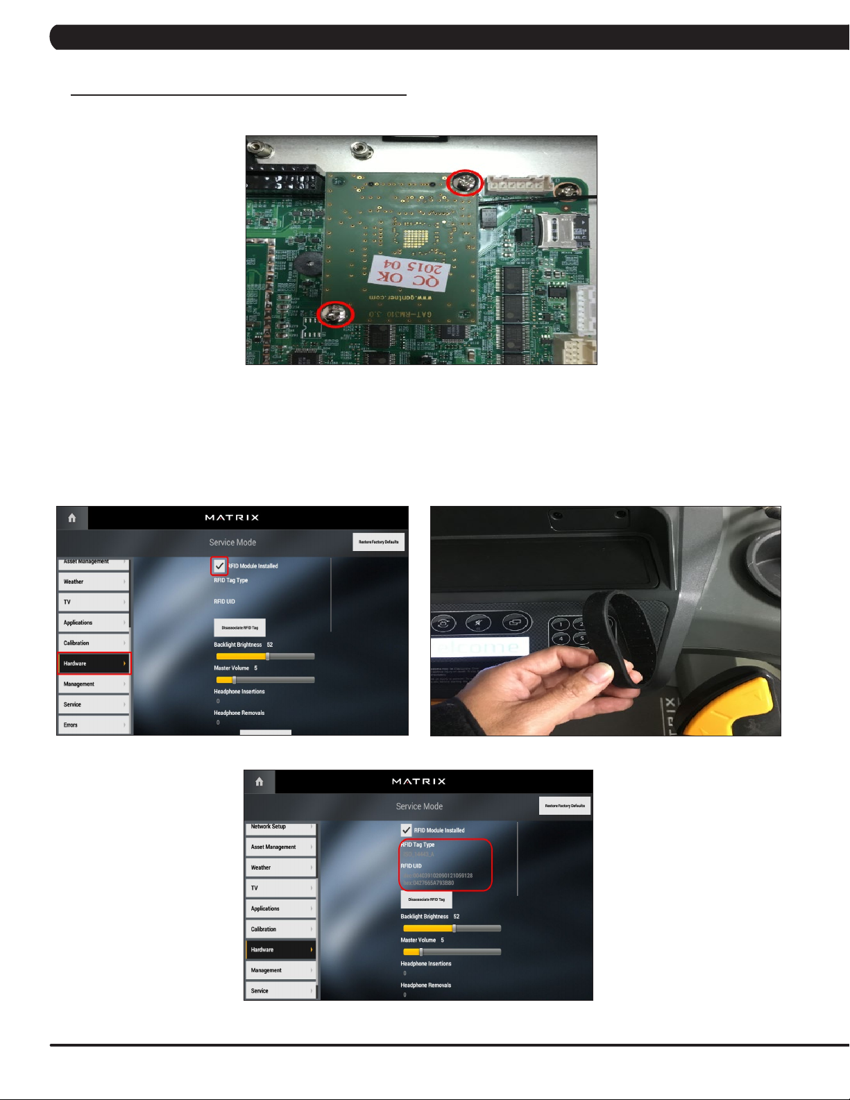
CHAPTER 10: CONSOLE SPECIFICATIONS AND ASSEMBLY GUIDE
10.2 RFID INSTALLATION - CONTINUED
7. Plug in the Reader board to the UCB and use the two screw fix it (Figure G).
FIGURE G
7XE / T7XE / 7XI / T7XI RFID INSTALLATION
3.
1. Press the number key “enter,3001,enter” to the service mode, select the ”Hardware”. Click to select the “RFID Module Installed” on the screen
(Figure A).
2. Put the Wristband on console test it (Figure B) , If RFID working when the console will show this Wristband data on the screen (Figure C).
FIGURE BFIGURE A
56
FIGURE C
Page 59

CHAPTER 10: CONSOLE SPECIFICATIONS AND ASSEMBLY GUIDE
10.3 TV PROGRAMMING INSTRUCTIONS
Once the cardio equipment has been installed, and proper power and cable wiring is provided, The Television must be programmed to the club's
channels and settings.
1. Enter Update manager by pressing ENTER, 3, 0, 0, 1, ENTER on the lower keypad. Then select the TV and Source Selection "Coaxial",
after press the next to "TV Channel Setup" (Figure A).
2. Setting the “Source Selection / Country / Program List”, after press “Start Scan” to begin scanning (Figure B).
FIGURE BFIGURE A
3. Scan Started will be displayed on the screen (Figure C).
FIGURE C
57
Page 60
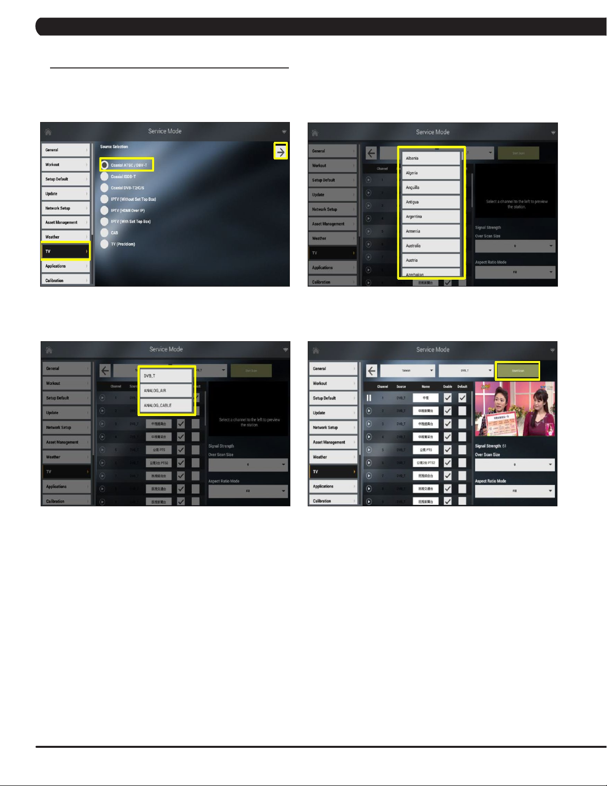
CHAPTER 10: CONSOLE SPECIFICATIONS AND ASSEMBLY GUIDE
10.4 US AND KM TUNER SETTING SOP
10.4.1 Coaxial ATSC / DVB-T
1. Enter “3001” to 7xi Service Mode then choose “TV” button to the setup page. A “Source Selection” screen will show on the display: Select the
Coaxial ATSC / DBV-T (Figure A ~ D).
Select the Country.
FIGURE BFIGURE A
Select the TV source. Press the Start Scan.
FIGURE C
FIGURE D
58
Page 61
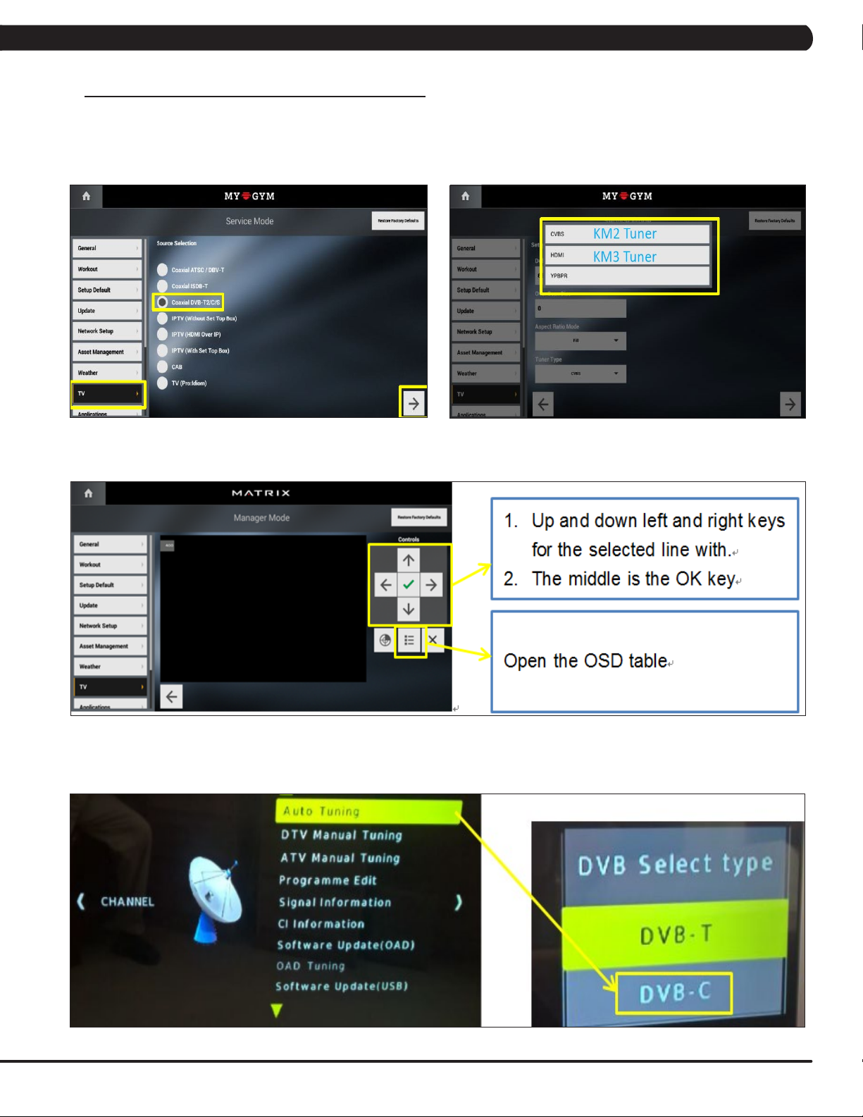
CHAPTER 10: CONSOLE SPECIFICATIONS AND ASSEMBLY GUIDE
10.4 US AND KM TUNER SETTING SOP - CONTINUED
10.4.2 Coaxial DVB-T2 / C / S
1. Enter “3001” to 7xi Service Mode then choose “TV” button to the setup page. A “Source Selection” screen will show on the display: Select
the Coaxial DVB-T2 / C / S.
Select the tuner type: KM2 -> CVBS / KM3 -> HDMI.
FIGURE BFIGURE A
10.4.2.1 DVB – C / T tuning
Auto Tuning -> select the TV source DVB – C / T.
FIGURE C
FIGURE D
59
Page 62
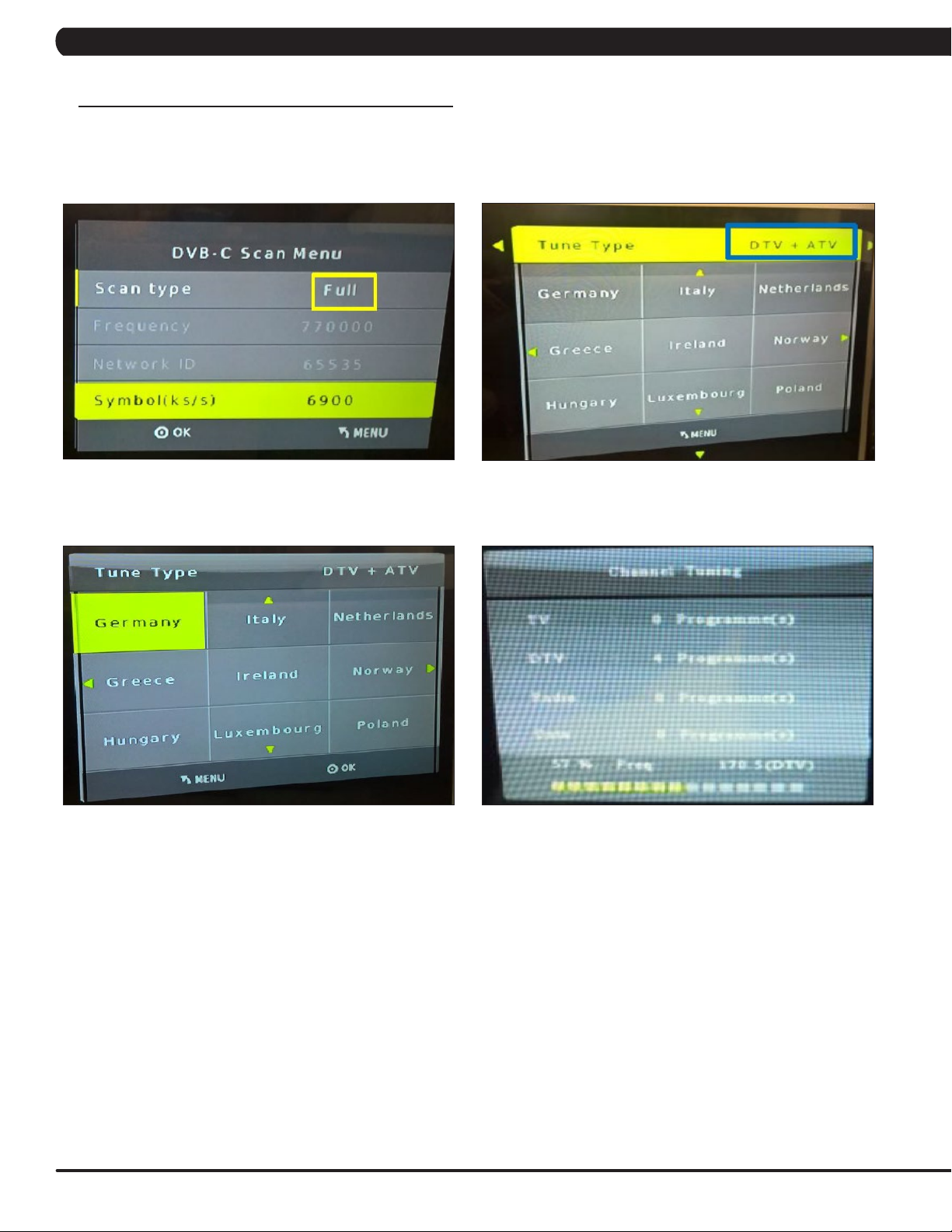
CHAPTER 10: CONSOLE SPECIFICATIONS AND ASSEMBLY GUIDE
10.4 US AND KM TUNER SETTING SOP - CONTINUED
10.4.2 Coaxial DVB-T2 / C / S – continued
10.4.2.1 DVB – C / T tuning – continued
Select scan type to “Full”. Select tune type (DTV/ATV/DTV+ATV).
FIGURE FFIGURE E
Select country areas and start the channel auto tuning.
FIGURE HFIGURE G
60
Page 63

CHAPTER 10: CONSOLE SPECIFICATIONS AND ASSEMBLY GUIDE
10.4 US AND KM TUNER SETTING SOP - CONTINUED
10.4.2 Coaxial DVB-T2 / C / S – continued
10.4.2.2 DVB- S (S: Satellite) tuning
Enter the Input Source and select the DVB-S2 to store setting.
FIGURE I
Enter the Dish Setup.
FIGURE J
FIGURE K
61
Page 64

CHAPTER 10: CONSOLE SPECIFICATIONS AND ASSEMBLY GUIDE
10.4 US AND KM TUNER SETTING SOP - CONTINUED
10.4.2 Coaxial DVB-T2 / C / S – continued
10.42.2 DVB- S (S: Satellite) tuning – continued
Channel tuning is started and showed the result. Insert the CI card to KM2 tuner if you have it.
FIGURE MFIGURE L
10.4.3 Coaxial ISDB-T (only for Japan)
1. Enter “3001” to 7xi Service Mode then choose “TV” button to the setup page. A “Source Selection” screen will show on the display: Select the
Coaxial ISDB-T.
Select the tuner type: CVBS.
FIGURE BFIGURE A
62
Page 65

CHAPTER 10: CONSOLE SPECIFICATIONS AND ASSEMBLY GUIDE
10.5 IPTV SETTING SOP
IPTV (Without Set Top Box)
1. Enter “3001” to 7xi Service Mode then choose “TV” button to the setup page. A “Source Selection” screen will show on the display : Select
the IPTV (Without Set Top Box)
FIGURE A
2. Use the bottom right arrow to go to the 2rd page of the TV settings. Make sure the USB stick is plugged in and click on Import Channel List
(this should import all the channels).
FIGURE B
63
Page 66

CHAPTER 10: CONSOLE SPECIFICATIONS AND ASSEMBLY GUIDE
10.5 IPTV SETTING SOP
IPTV (Without Set Top Box)
3. Press the “ +” bottom add the each IPTV channel base on vendor provided Protocol / IP Address / Port.
Note :
1. If IPTV source of SAP channel, please select the “Use SAP channel list.
2. When the finish first console IPTV setting, Make sure the USB stick is plugged in and click on Import Channel List (this should import all
the channels).
3. Run a workout, click on the TV app, and check if the IPTV is working.
4. Return to the workout main screen and verify that the internet connection is working by running a web app.
FIGURE C
64
Page 67

CHAPTER 10: CONSOLE SPECIFICATIONS AND ASSEMBLY GUIDE
10.5 IPTV SETTING SOP - CONTINUED
HDMI-Over IP / STB assembly
1. Connect the IR extend wire between STB and HDMI-over-IP box input. NOTE: The IR extend wire receiver needs to be at the STB IR receiver
position.
FIGURE A
2. Connect the HDMI cable between the STB and HDMI-over-IP box input. NOTE: Or select the Component and RCA input at HDMI-IP box right
side.
FIGURE B FIGURE C
FIGURE D
65
Page 68
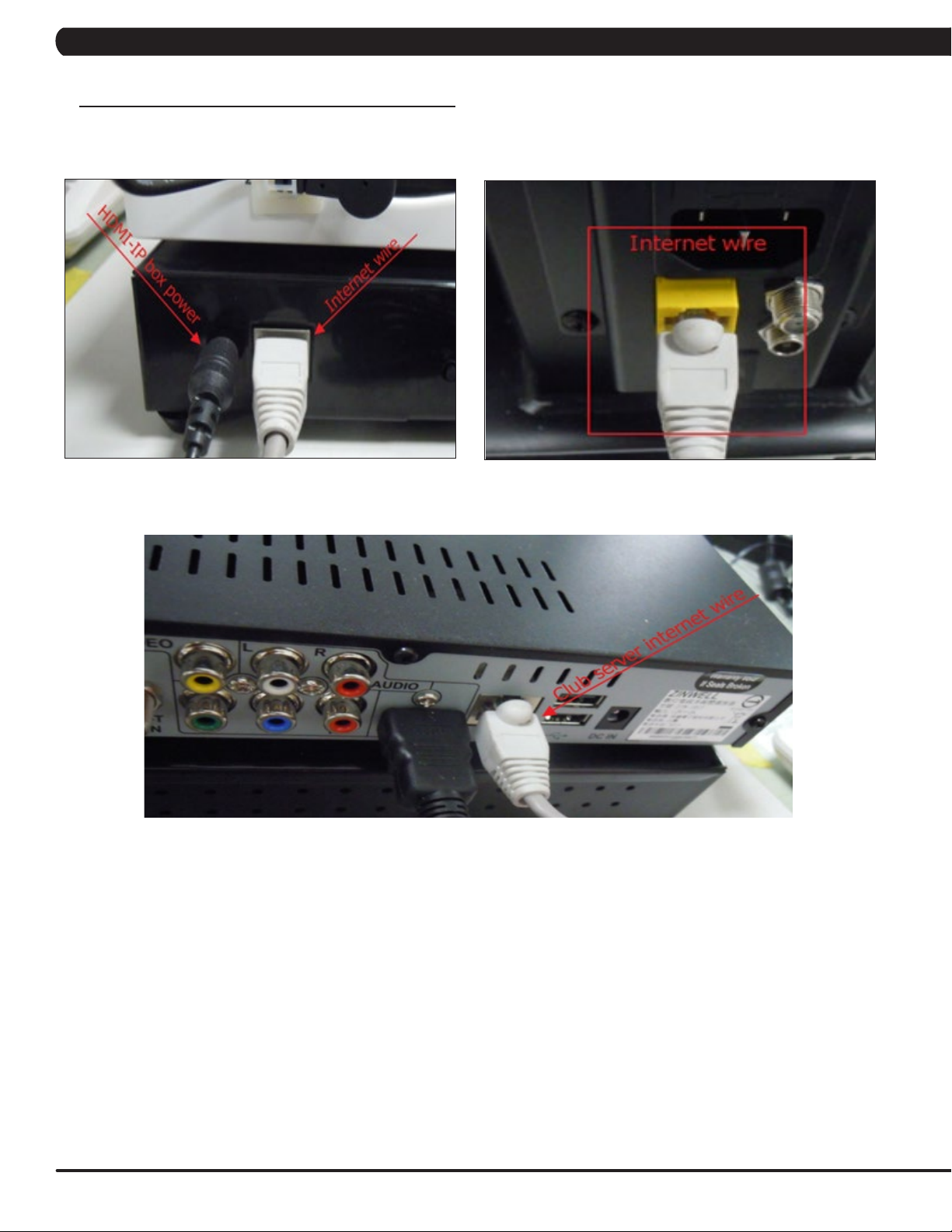
CHAPTER 10: CONSOLE SPECIFICATIONS AND ASSEMBLY GUIDE
10.5 IPTV SETTING SOP - CONTINUED
HDMI-Over IP / STB assembly - continued
1. Connect the HDMI-IP power wire and internet wire between HDMI-over-IP box and machine internet connector.
FIGURE A FIGURE B
2. Connect the customer location internet wire to STB.
FIGURE C
66
Page 69
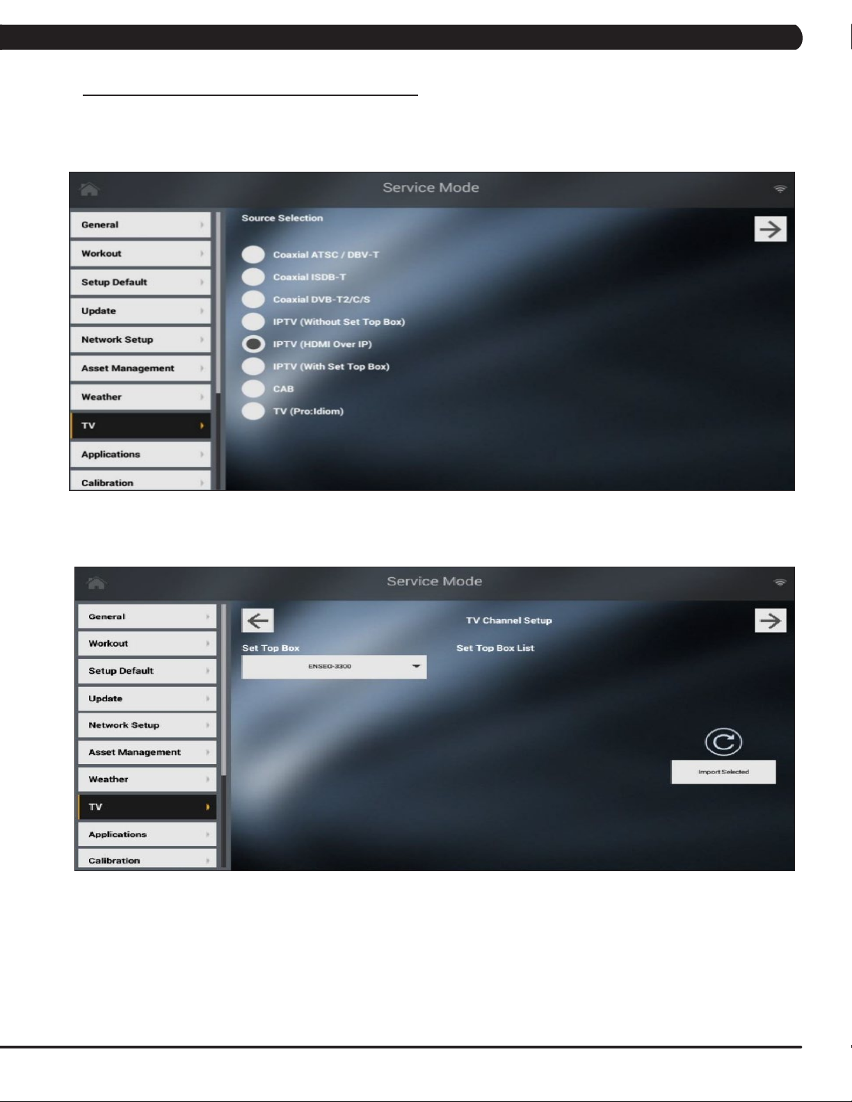
CHAPTER 10: CONSOLE SPECIFICATIONS AND ASSEMBLY GUIDE
10.5 IPTV SETTING SOP - CONTINUED
IPTV (HDMI Over IP) setting
1. Enter “3001” to 7xi Service Mode then choose “TV” button to the setup page. A “Source Selection” screen will show on the display: Select the
IPTV (HDMI Over IP ) - Figure A.
FIGURE A
2. An import button on this page is created to let user add set top box remote settings. Plug in a USB disk with settopboxupdatesettings.xml
should list all supported set top box and choose one of them to import (Figure B).
FIGURE B
67
Page 70
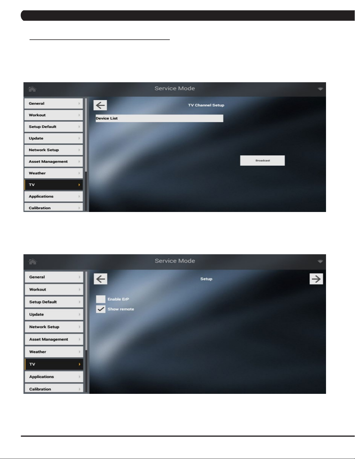
CHAPTER 10: CONSOLE SPECIFICATIONS AND ASSEMBLY GUIDE
10.5 IPTV SETTING SOP - CONTINUED
IPTV (HDMI Over IP) setting - continued
3.Onthe“IPTVHDMIOverIPSetup”page,usercantouchthebroadcastbuttontondallavailabledevicesinthesamesubnet.Ifthereare
at least one device is available, a “Connect” button will appear. Touch this button for create connection. After the console is connecting to the
device, a playback area and a control panel will show up. The control panel is created for the device setting, not for set top box. There are couple
settingswecanadjustforHDMIdevices,especiallyupdatermware(FiguresC).
FIGURE C
4. Option “IPTV HDMI Show Remote” is created for show/hide remote icons on the playback area. If this option is “True”, the remote icon will
show on the playback during the workout. This option won’t affect the HDMI over IP set up page in manager mode. A remote icon will always pop
up in manager mode (Figures D).
68
FIGURE D
Page 71
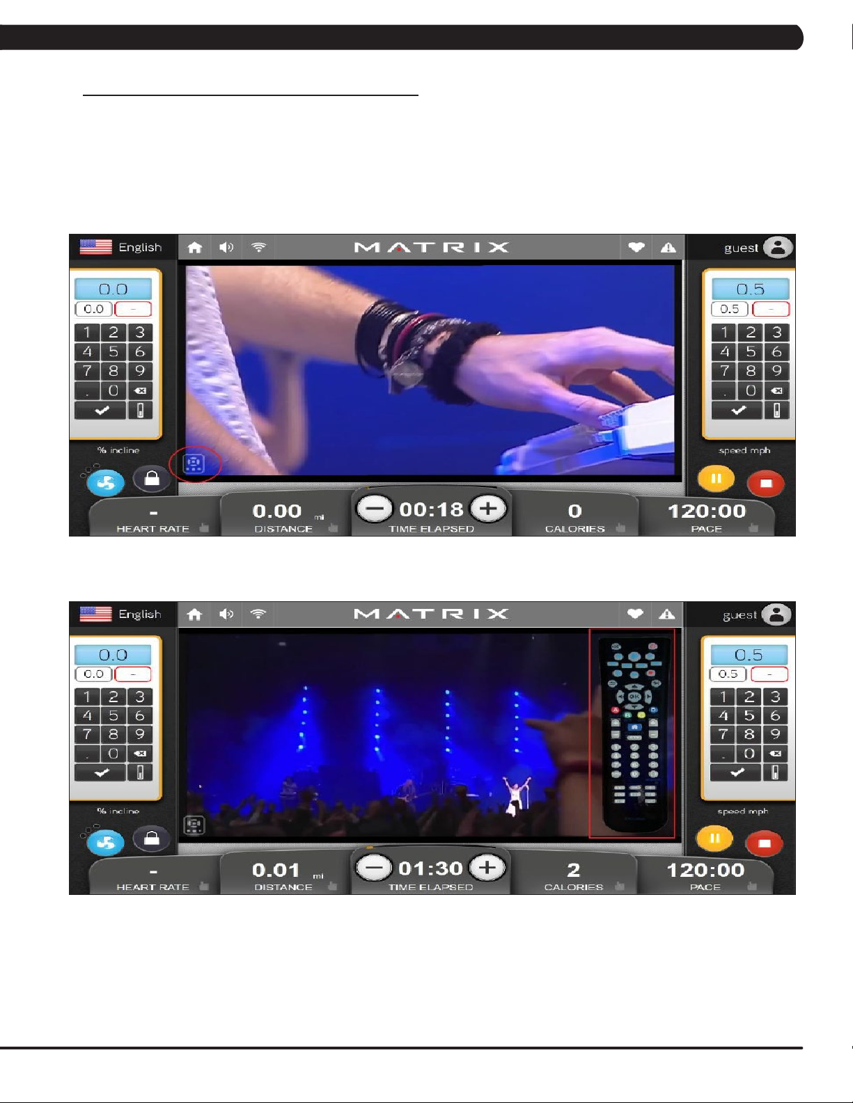
CHAPTER 10: CONSOLE SPECIFICATIONS AND ASSEMBLY GUIDE
10.5 IPTV SETTING SOP - CONTINUED
IPTV (HDMI Over IP) setting
5. Back to the start window then start the workout, the TV app should replace by HDMI over IP function. A small remote icon on the bottom left of
TV screen should be seen if option “IPTV HDMI Show Remote” is “True”, touch this icon will pop up a remote image on the playback (Figure E).
User can control the set top box by touch any of buttons on the image or enter the predefined multimedia key pad like channel up/down to control
the set top box. (The remote would be hidden in 10 seconds if no button being touched, automatically.) Touch the button on the remote should
send the relative command to the device. For example, touch 2 channel up button should change channel, mute button should mute the volume,
etc (Figure F).
FIGURE E
FIGURE F
69
Page 72
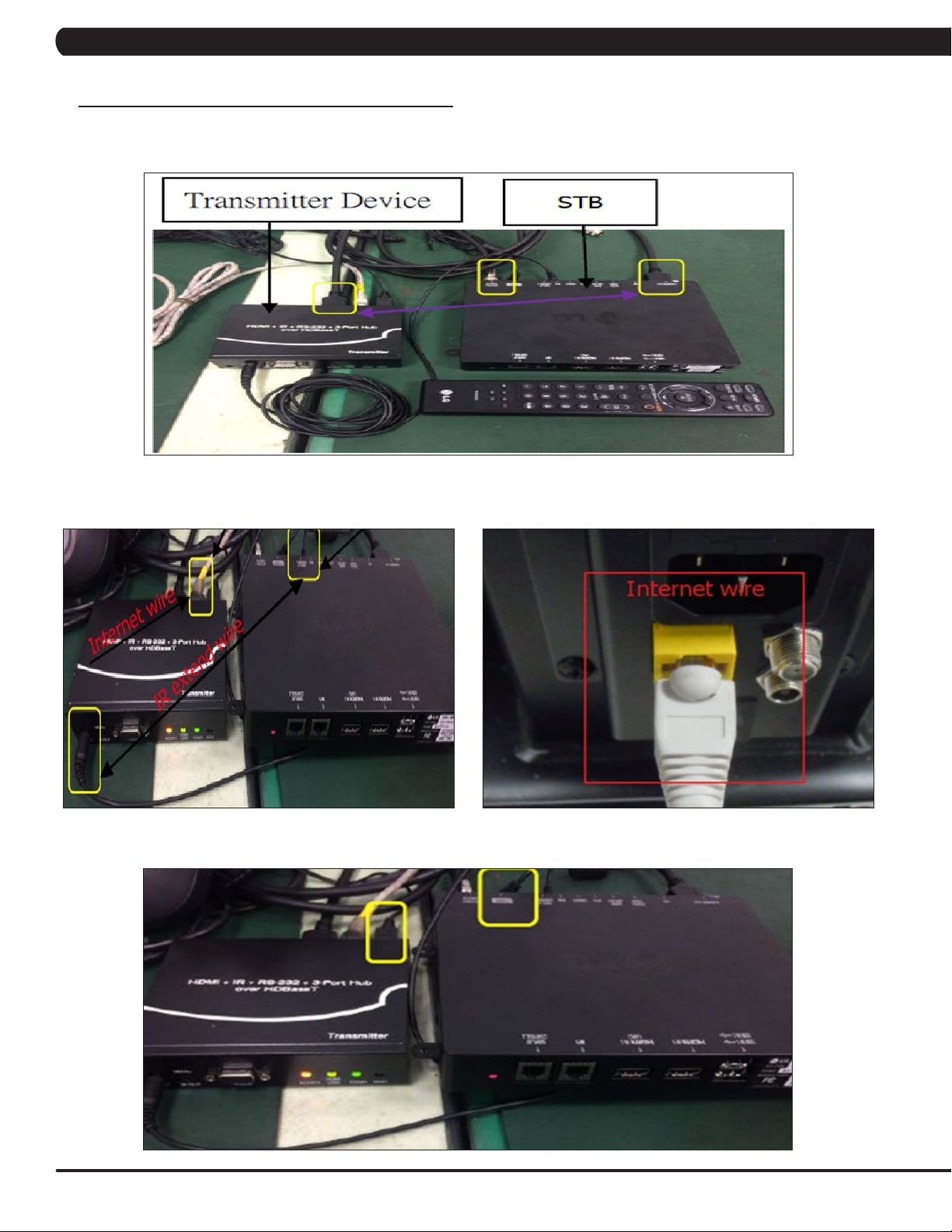
CHAPTER 10: CONSOLE SPECIFICATIONS AND ASSEMBLY GUIDE
10.5 IPTV SETTING SOP - CONTINUED
IHD Base-T / STB assembly
1. Connect the HDMI cable between the STB and HD Base-Transmitter input (Figure A).
FIGURE A
2. Connect the IR extend wire between STB and HDMI-IP input and internet wire between HDMI-IP box and machine internet connector (Figures
B & C). Note: The IR extend wire receiver need at the STB IR receiver position.
FIGURE B FIGURE C
3. Connect the HD Base-Transmitter and STB power wire (Figure D).
70
FIGURE D
Page 73

CHAPTER 10: CONSOLE SPECIFICATIONS AND ASSEMBLY GUIDE
10.5 IPTV SETTING SOP - CONTINUED
IPTV (With Set Top Box) setting
1. Enter “3001” to 7xi Service Mode then choose “TV” button to the setup page. A “Source Selection” screen will show on the display: Select the
IPTV (With Set Top Box ).
FIGURE A
2. An import button on this page is created for let user add set top box remote settings. Plug in an USB disk with settopboxupdatesettings.xml
should list all supported set top box and choose one of them to import.
FIGURE B
3. An import button on this page after the console is connecting to the device, a playback area and a control panel will show up.
FIGURE C
71
Page 74
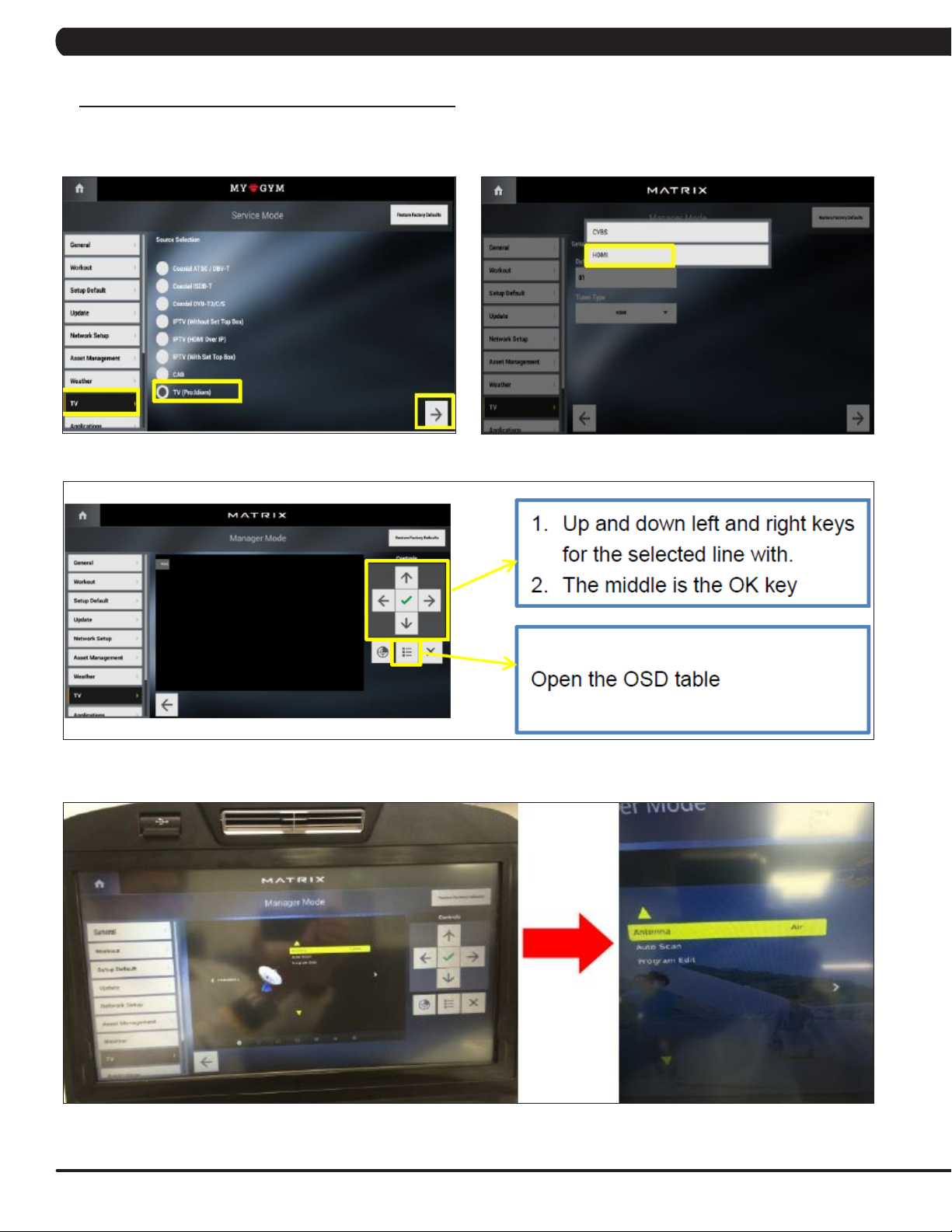
CHAPTER 10: CONSOLE SPECIFICATIONS AND ASSEMBLY GUIDE
10.6 TV (PRO:IDIOM) SETTING SOP
1. Enter “3001” to 7xi Service Mode then choose “TV” button to the setup page. A “Source Selection” screen will show on the display: Select
the Select the TV (Pro:Idiom).
Select the tuner type: HDMI.
FIGURE BFIGURE A
Enter the Antenna and select the source: Air / Cable.
FIGURE C
FIGURE D
72
Page 75

CHAPTER 10: CONSOLE SPECIFICATIONS AND ASSEMBLY GUIDE
10.6 TV (PRO:IDIOM) SETTING SOP - CONTINUED
Select the Auto Scan and start the channel auto tuning.
FIGURE E
73
Page 76
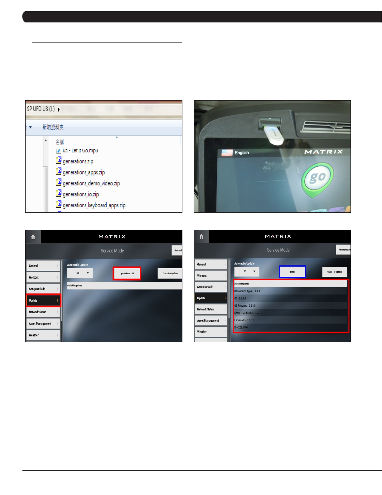
CHAPTER 11: SOFTWARE UPGRADE PROCEDURE
11.1 SOFTWARE UPGRADE PROCEDURE FROM USB
NOTE: Don't power off the machine while the software is being installed. After the software has been installed completely, turn off the
machine and wait 30 seconds, then turn the machine back on. If the display shows 04A0, turn off & turn on the machine again.
1) Copy the Generations software onto the USB drive (Figure A).
2) Insert the USB Drive into the USB port in the console (Figure B).
3) Enter Update manager by pressing ENTER, 3, 0, 0, 1, ENTER on the lower keypad. Then select the Update and update source "Update
from USB" (Figure C).
4) Press the "Install" to auto run the upgrade process (Figure D).
FIGURE A FIGURE B
FIGURE C FIGURE D
74
Page 77
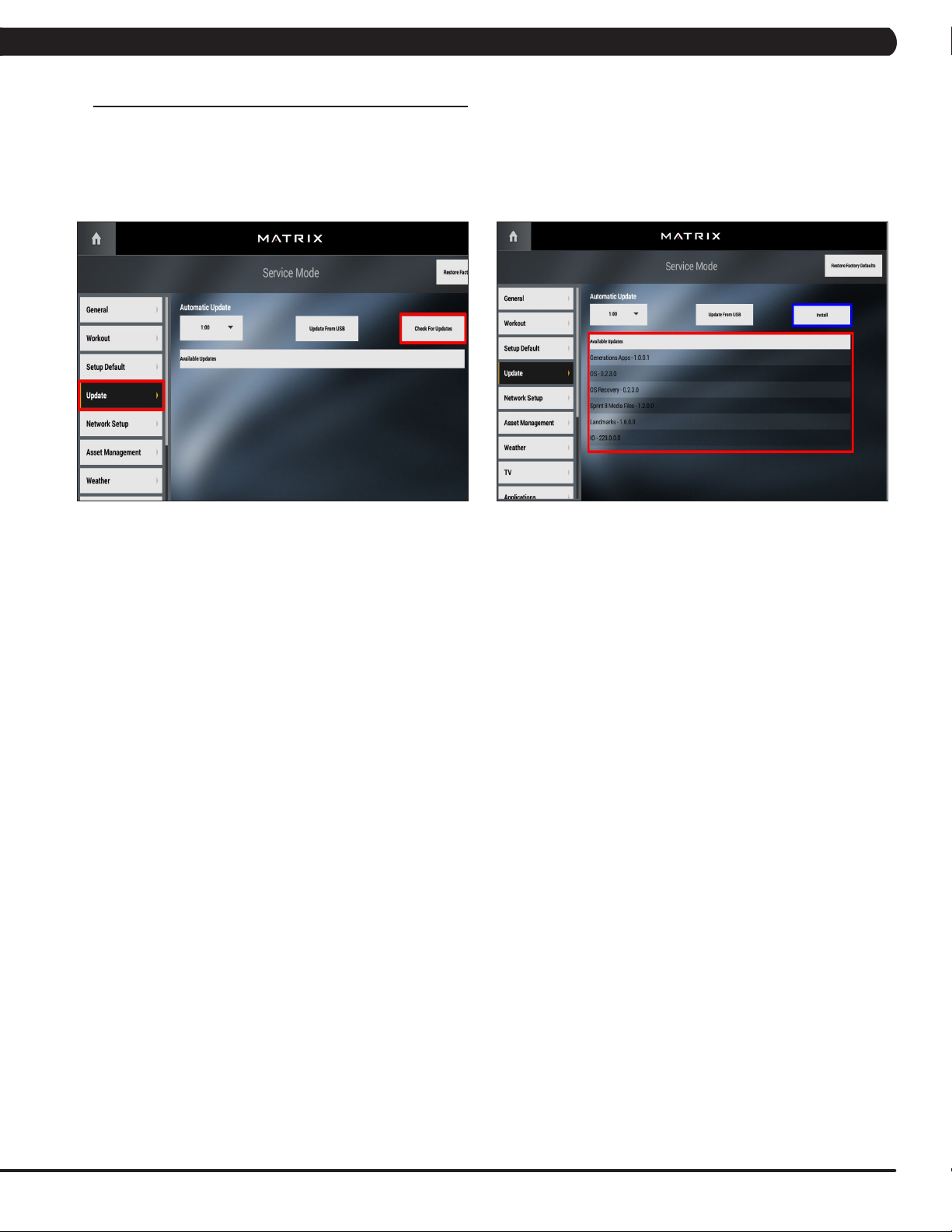
CHAPTER 11: SOFTWARE UPGRADE PROCEDURE
11.2 SOFTWARE UPGRADE PROCEDURE FROM WEBSITE
NOTE: Don't power off the machine while the software is being installed. After the software has been installed completely, turn off the
machine and wait 30 seconds, then turn the machine back on. If the display shows 04A0, turn off & turn on the machine again.
1) Enter Update manager by pressing ENTER, 3, 0, 0, 1, ENTER on the lower keypad. Then select the Update and update source "Check for
Update" (Figure A).
2) Press the "Install" to auto run the upgrade process (Figure B).
FIGURE A FIGURE B
75
Page 78

NOTES
76
Page 79

MATRIX FITNESS SYSTEMS CORP.
1610 LANDMARK DRIVE COTTAGE GROVE WI 53527 USA
REV. 01
KO
77
 Loading...