

Page 1

2016 5X CONSOLE
SERVICE MANUAL
Page 2

TABLE OF CONTENTS
CHAPTER 1: SERIAL NUMBER LOCATION ........................................................... 1
C
HAPTER 2: IMPORTANT SAFETY INSTRUCTIONS
2.1
3.1
3.2
4.1 Console Description .................................................................................................. 4
4.2 Workout Setup Steps - Manual .................................................................................. 6
4.3 Workout Setup Steps - Training Workouts ................................................................. 5
4.4 Workout Setup Steps - Fitness Test ........................................................................... 7
4.5 Workout Setup Steps - Target Heart Rate ................................................................. 8
4.6 Workout Setup Steps - Constant Watts ..................................................................... 8
4.7 Workout Setup Steps - Sprint 8 ................................................................................. 8
4.8 Workout Setup Steps - Goal Training ........................................................................ 8
4.9 Workout Setup Steps - Landmarks ............................................................................ 8
4.10 Workout Setup Steps - 5k Run .................................................................................. 9
4.11 Workout Setup Steps - Auto Calibration .................................................................... 9
5.1 Manager Mode Overview ........................................................................................... 10
6.1 Engineering Mode Overview ...................................................................................... 14
CHAPTER 7: SERVICE MODE/TEST MODE
Electrical Requirements
C
HAPTER 3: PREVENTATIVE MAINTENANCE
Recommended
Check for Damaged Parts
C
HAPTER 4: CONSOLE OVERLAY AND WORKOUT DESCRIPTION
CHAPTER 5: MANAGER MODE
CHAPTER 6: ENGINEERING MODE
Cleaning Tips .................................................................................... 3
............................................................................................. 2
......................................................................................... 3
7.1 Service Mode Overview ............................................................................................. 15
7.2 Test Mode Overview................................................................................................... 16
CHAPTER 8: TROUBLESHOOTING
8.1
8.2
9.1
9.2
9.3
10.1
10.2
10.3 HURESA5X MYE TV/PCTV Bracket Installation .......................................................... 53
10.4
10.5
10.6
10.7
1.1
1
1.2
1
Electrical Diagram ...................................................................................................... 17
Error Codes List
CHAPTER 9: PARTS REPLACEMENT GUIDE
Console Replacement ..................................................................................................... 35
Console Keypad/Overlay Replacement
esting the Unit ............................................................................................................... 38
T
C
HAPTER 10: TREADMILL SPECIFICATIONS AND ASSEMBLY GUIDE
WiFi installation .............................................................................................................. 39
RFID installation
C5X MYE
C5X PCTV Bracket Installation ...................................................................................... 64
T5X MYE
T5X PCTV Bracket Installation ...................................................................................... 73
C
HAPTER 11: SOFTWARE UPGRADE GUIDE
Software Upgrade Instructions for UCB ...................................................................... 77
Software Upgrade Instructions for LCB ...................................................................... 78
.......................................................................................................... 30
........................................................................ 36
............................................................................................................. 45
TV Bracket Installation .................................................................................. 58
TV Bracket Installation .................................................................................. 69
Page 3
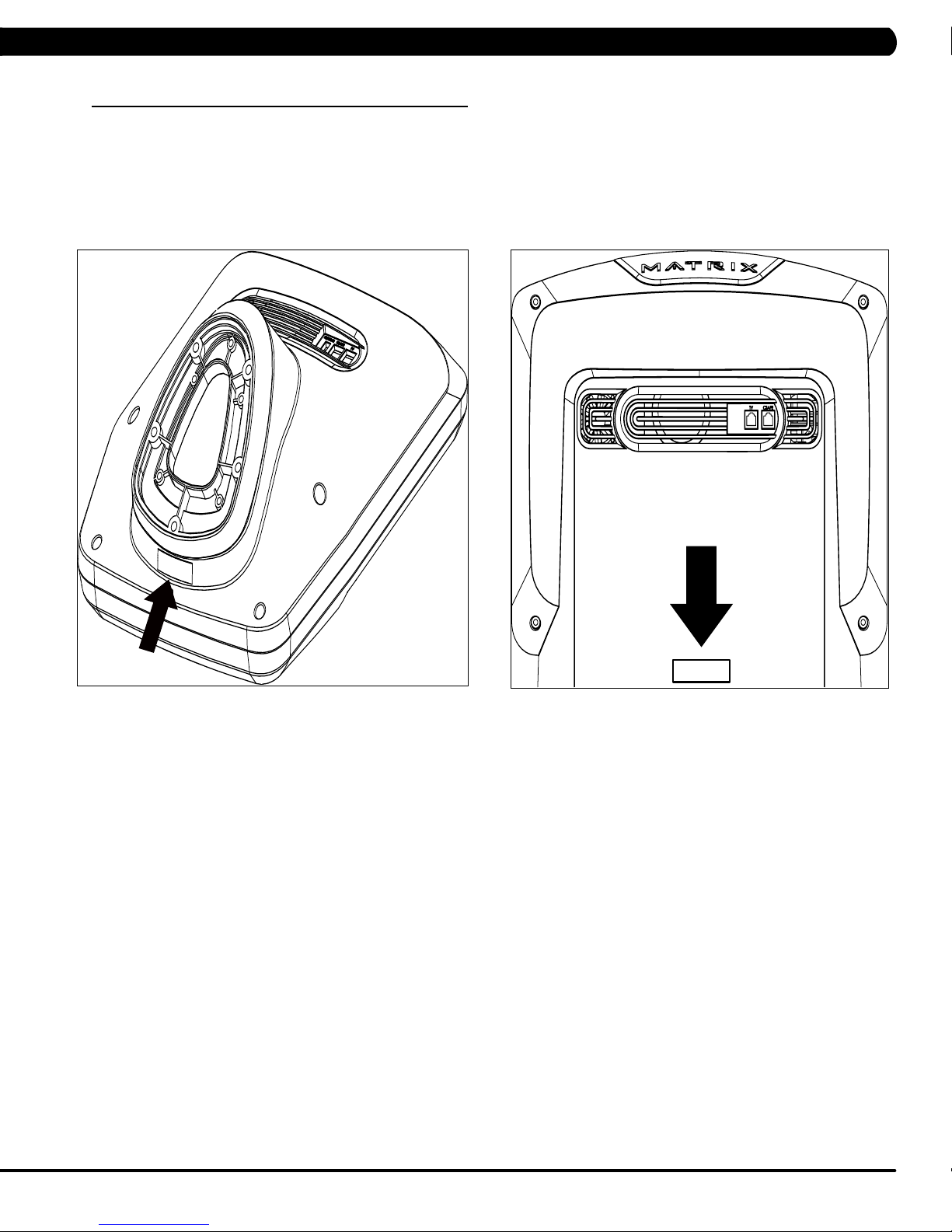
1.1 SERIAL NUMBER LOCATION
CHAPTER 1: SERIAL NUMBER LOCATION
CONSOLE SERIAL NUMBER LOCATION
5X
T5X
1
Page 4
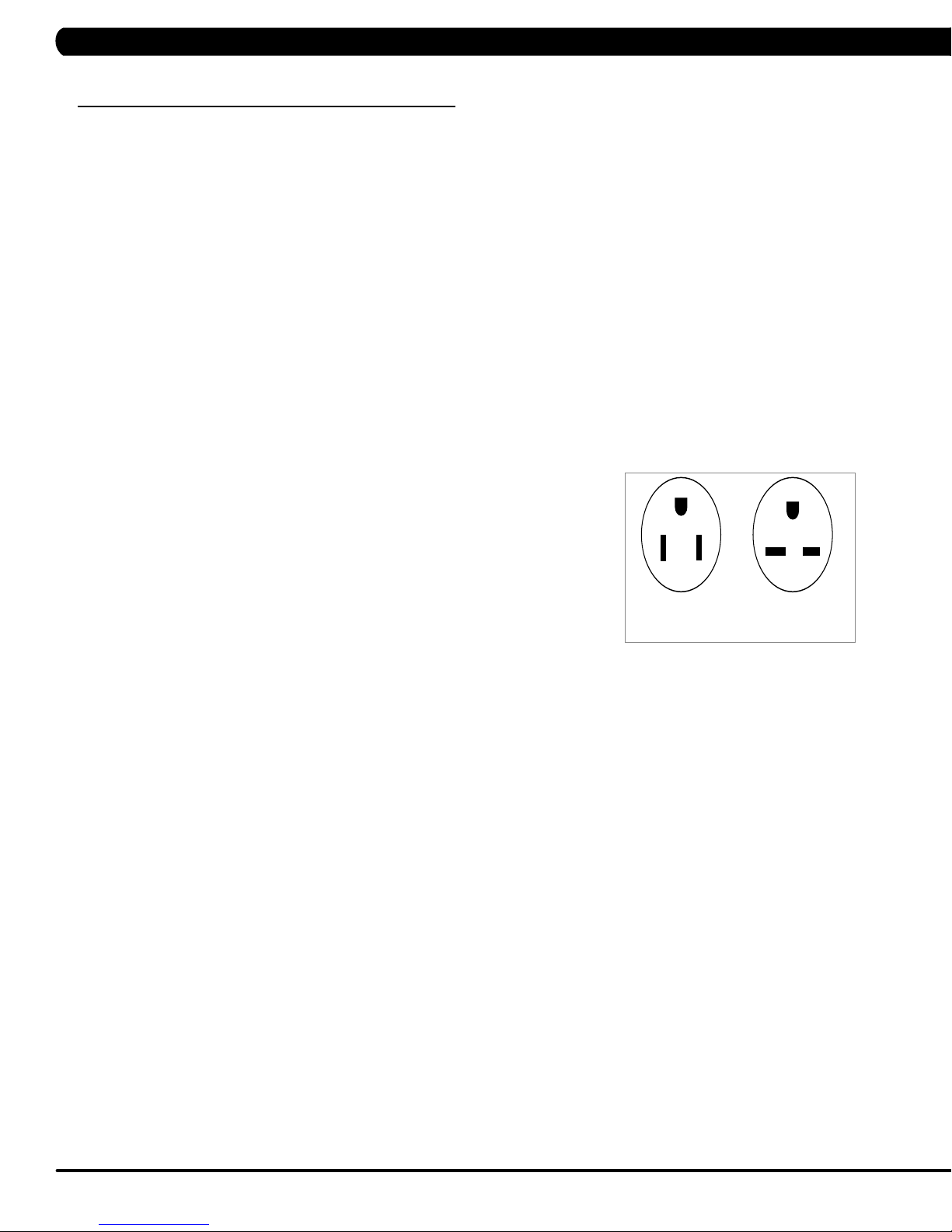
CHAPTER 2: IMPORTANT SAFETY INFORMATION
220 NEMA 6-15P
PLUG
110 NEMA 5-15P
PLUG
2.1 ELECTRICAL REQUIREMENTS
DEDICATED CIRCUIT AND ELECTRICAL INFO
A “Dedicated Circuit” means that each outlet you plug into should not have anything else running on that same circuit. The easiest way to verify
this is to locate the main circuit breaker box, and turn off the breaker(s) one at a time. Once a breaker has been turned off, the only thing that
should not have power to it are the units in question. No lamps, vending machines, fans, sound systems, or any other item should lose power
when you perform this test. Non-looped (isolated) neutral/grounding means that each circuit must have an individual neutral/ground connection
coming from it, and terminating at an approved earth ground. You cannot “jumper” a single neutral/ground from one circuit to the next.
ELECTRICAL REQUIREMENTS
For your safety and to ensure good unit performance, the ground on this circuit must be non-looped (isolated). Please refer to NEC article 210-21
and 210-23. Any alterations to the standard power cord provided could void all warranties of this product.
The 3x, 5x and 7xe bikes are designed to be self-powered and do not require an external power supply source to operate. Without an external
power supply, the console’s start-up time may be delayed. Add-on TV’s and other console accessories will increase the time needed for start-up.
An external power supply will ensure power is provided to the console at all times and is recommended when add-on accessories are used.
For units with an integrated TV (like the 7xe and 7xi), the TV power requirements are included in the unit. An RG6 coaxial cable with ‘F Type’
compression fittings on each end will need to be connected to the cardio unit and the video source. Additional power requirements are not needed
for the add-on digital TV (3x and 5x). For units with an add-on PCTV (3x and 5x), the TV power requirements are separate.
NOTE: ALL UNITS WITH VIRTUAL ACTIVE™ MUST BE POWERED!
110 V UNITS
All Matrix 3x, 5x, 7xe and 7xi 110 V bikes require the use of a 100-125 V, 60 Hz and a 15 A
“Dedicated Circuit”, with a non-looped (isolated) neutral/ground for power. This outlet should be a
NEMA 5-15R and have the same configuration as the plug. No adapter should be used with this
product. These bikes can be daisy-chained together with up to 4 units per 15 A dedicated circuit.
Matrix daisy-chain cord adapters are sold separately.
220 V UNITS
All Matrix 3x, 5x, 7xe and 7xi 220 V bikes require the use of a 216-250 V, 50 Hz and a 15 A
“Dedicated Circuit”, with a non-looped (isolated) neutral/ground for power. This outlet should be a
NEMA 6-15R and have the same configuration as the plug. No adapter should be used with this
product. These bikes can be daisy-chained together with up to 4 units per 15 A dedicated circuit.
Matrix daisy-chain cord adapters are sold separately.
GROUNDING INSTRUCTIONS
The unit must be grounded. If it should malfunction or breakdown, grounding provides a path of
least resistance for electric current to reduce the risk of electric shock. The unit is equipped with a cord having an equipment-grounding conduc
tor and a grounding plug. The plug must be plugged into an appropriate outlet that is properly installed and grounded in accordance with all local
codes and ordinances. If the user does not follow these grounding instructions, the user could void the Matrix limited warranty.
ADDITIONAL ELECTRICAL INFO
In addition to the dedicated circuit requirement, the proper gauge wire must be used from the circuit breaker box, to each outlet that will have the
maximum number of units running off of it. If the distance from the circuit breaker box to each outlet, is 100 ft (30.5 m) or less, then 12 gauge wire
should be used. For distances greater than 100 ft (30.5 m) from the circuit breaker box to the outlet, a 10 gauge wire should be used.
ENERGY SAVING / LOW- POWER MODE
All units are configured with the ability to enter into an energy saving / low-power mode when the unit has not been in use for a specified period
of time. Additional time may be required to fully reactivate this unit once it has entered the low-power mode. This energy saving feature may be
enabled or disabled from within the ‘Manager Mode’ or ‘Engineering Mode.
North American power cord plugs shown.
Depending on your country, the plug type may vary.
-
ADD-ON PCTV (3X AND 5X)
A 15 A or 20 A “Dedicated Circuit” with a non-looped (isolated) neutral/ground is required. Each PCTV requires at least 1.2 A of current. No more
than 12 PCTVs should be used for each 15 A circuit and no more than 16 PCTVs should be used for each 20 A circuit. The power outlet should
have the same configuration as the plug. No adapter should be used with this product. An RG6 coaxial cable with ‘F Type’ compression fittings
will need to be connected between the video source and each add-on PCTV unit. See the PCTV Manual for web connection requirements.
ADD-ON DIGITAL TV (3X AND 5X)
Additional power requirements are not needed for the add-on digital TV. An RG6 coaxial cable with ‘F Type’ compression fittings will need to be
connected between the video source and each add-on digital TV unit.
BATTERY CHARGING (3X AND 5X)
The bike saves its batter charge by moving into a shutdown mode whenever PEDAL FASTER appears on the display. If the user does not
maintain a pedal rate of 40 RPM or higher, a 30 second shutdown process begins. When the battery voltage is low, LOW BATTERY appears
on the display. This means it is time to recharge the battery. If the battery must be charged, use the optional power adapter charging unit. The
charger should be connected to the bike for a minimum of eight hours to ensure a thorough charge.
2
Page 5

CHAPTER 3: PREVENTATIVE MAINTENANCE
3.1 RECOMMENDED CLEANING TIPS
In order to maximize life span, and minimize down time, all Matrix Fitness Equipment requires regularly
scheduled cleaning.
YOU WILL NEED:
- Mild dish soap and water mixture in a spray bottle.
- Lint-free, 100% cotton cleaning cloths or Microfiber cleaning cloths.
DAILY:
1. Wipe down the unit after each use with a mild dish soap and water mixture. NOTE: Spray the soap/water mixture onto the cloth. NEVER
spray directly onto the equipment. We recommend that you do NOT allow customers to use spray bottles to clean the equipment. If the
cleaner is sprayed directly on the equipment or overspray is present, it may cause your equipment to rust and/or cause damage to console
overlays.
WEEKLY:
1. With a clean, dry, 100% lint-free cloth and water/soap mixture, wipe down the entire console area including the hand grips and hand
rails.
3.2 C
HECK FOR DAMAGED PARTS
DO NOT use any equipment that is damaged or has worn or broken parts. Use only replacement parts supplied by Matrix Fitness Systems.
MAINTAIN LABELS AND NAMEPLATES. Do not remove labels for any reason. They
contact Matrix Fitness Systems for a replacement. 1-866-693-4863, www.matrixfitness.com
MAINTAIN ALL EQUIPMENT Preventative maintenance is the key to smooth operating equipment. Equipment needs to be inspected at
regular intervals. Defective components must be replaced immediately. Improperly working equipment must be kept out of use until it is
repaired. Ensure that any person(s) making adjustments or performing maintenance or repair of any kind is qualified to do so. Matrix Fitness
Systems will provide service and maintenance training at our corporate facility upon request or in the field if proper arrangements are made.
contain important information. If unreadable or missing,
3
Page 6
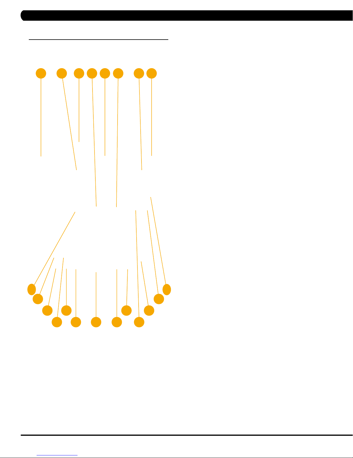
CHAPTER 4: CONSOLE OVERLAY AND WORKOUT DESCRIPTION
4.1 CONSOLE DESCRIPTION
e.g. A5X CONSOLE SHOWN
H
A B G
5X CONSOLE DESCRIPTION
ED F
I
A) WORKOUT KEYS: Simple program view and selection buttons.
B)GO
C)EN
D)UP/DOWN INCLINE (A5X ONLY):
E)U
F)U
G) STOP: Ends workout and shows workout summary data.
H)TOGGLE DISPLAY:
I)
J)
K)
L)F
M)
: One Touch Start.
TER: To confirm each program setting.
Easy information and incline
selection.
P/DOWN LEVEL: Easy information and level selection.
P/DOWN TIME: Easy information and time adjustment.
Cycles between 2 or 4 rows of workout
information displayed in LED window. The console will
automatically cycle between the workout information if the Toggle
Display button is pushed and held down for 3 seconds.
N
UMBER KEYPAD: W
adjustment during workout.
COOL D
LA
speeds).
R
feature).
OWN: Puts the Ascent into Cool Down mode.
NGUAGE: Select Language.
AN:
Allows for fan speed selection (fan has three operating
FID SENSOR:
orkout data input for workout setup. Level
Wireless login access location (optional add-on
5X ENTERTAINMENT ZONE
N) HOME: No function on this model.
O)LA
ST CHANNEL:
channel and the previous channel they were viewing.
P) CC
: Turns closed captioning on or off.
UTE: Mutes sound.
Q)M
VOL
J
N
P
Q
O
R
S
U
T
K
L
M
R)
C
S) NUMBER KEYPAD: Allows for easy number inputs.
T)
U)
UME UP/DOWN:
headphones.
CHA
NNEL UP/DOWN:
integrated
TV PO
WER: Turns external TV on or off.
Allows the user to cycle between the current
Adjusts the volume output through
Allows for channel selection on the
console TV.
4
Page 7
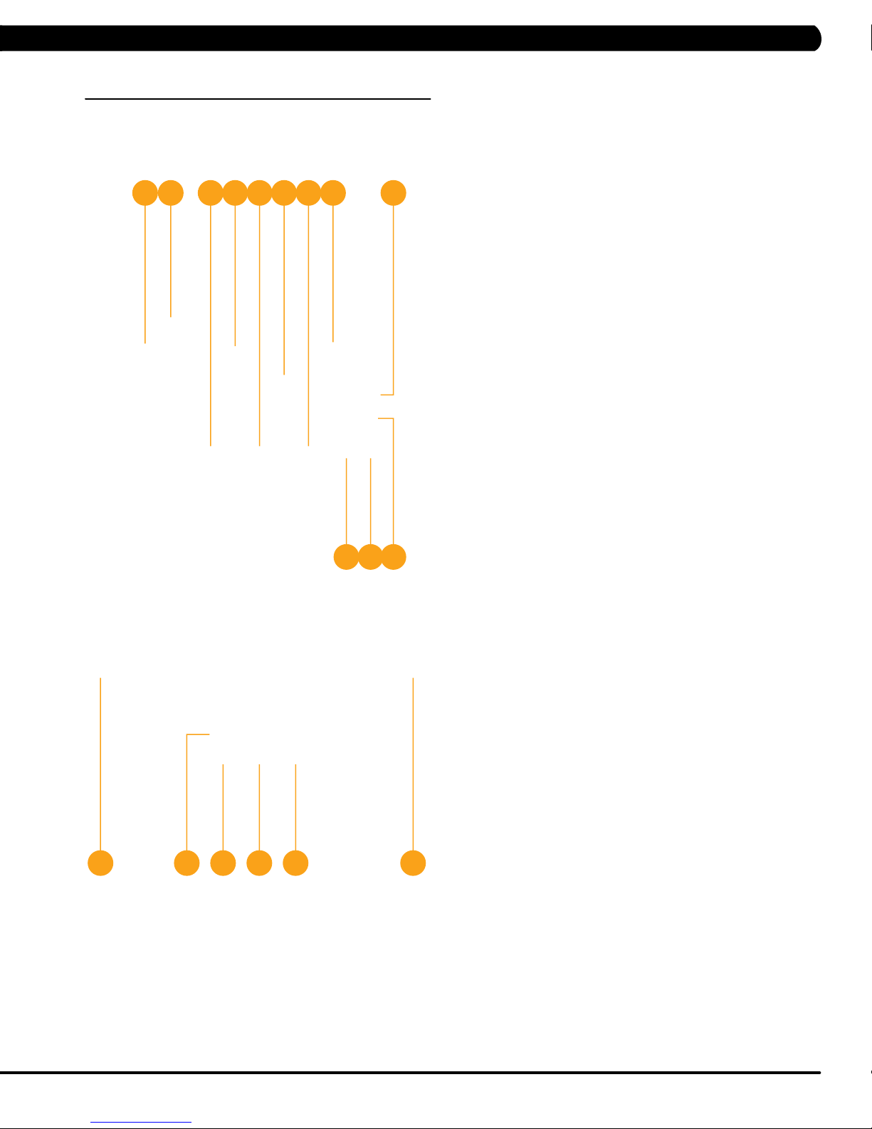
CHAPTER 4: CONSOLE OVERLAY AND WORKOUT DESCRIPTION
4.1 CONSOLE DESCRIPTION - CONTINUED
D M I F A H
B E
T5X CONSOLE DESCRIPTION
The Matrix machine is inspected before it is packaged. It is shipped
J
in two pieces: the base and the console. Carefully unpack the unit
and dispose of the box material. Note: There is a thin protective
sheet of clear plastic on the overlay of the console that should be
removed before use.
A)WORKOUT KEYS:
buttons. Press Fitness Test button to cycle through available
tests.
B)GO
C)EN
D)UP/DOWN INCLINE:
E)U
F)U
G)EM
N
L C
H)
I)PAUSE:
J)
: One Touch Start.
TER: To confirm each program setting.
selections.
P/DOWN SPEED:
selections.
P/DOWN TIME: Adjust time and make program selections.
ERGENCY STOP
functions and immobilize the unit. The emergency stop on
this treadmill must be returned to its original position in order
to allow normal operation of the unit.
P: Ends workout and shows workout summary data.
STO
Pauses workout. Pause duration can be set in
manager or engineering mode.
UMBER KEYPAD: W
N
Speed adjustment during workout.
Simple program view and selection
Adjust incline and make program
Adjust speed and make program
MMOBILIZATION: T
/ I
orkout data input for workout setup.
o stop all
K)
COOL D
Down time is dependent on the length of the workout.
Workouts 19 minutes and shorter will have a cool down
length of 2 minutes. Workouts 20 minutes and longer will
have a cool down length of 5 minutes.
L)F
speeds.)
T
M)
information displayed in LED window. The console will
BKD E
G
H
automatically cycle between the workout information if
the Toggle Display button is pushed and held down for 3
seconds.
N)LA
OWN:
Puts treadmill into Cool Down mode. Cool
Allows for fan speed selection (fan has three operating
AN:
OGGLE DISPLAY:
NGUAGE: Select Language.
Cycles between 4 rows of workout
5
Page 8

CHAPTER 4: CONSOLE OVERLAY AND WORKOUT DESCRIPTION
4.2 WORKOUT SETUP STEPS - MANUAL
GO - Press to immediately begin a workout. Workout, resistance
level, and time will automatically go to default settings. Pressing
GO will not prompt user for age, weight, or level settings.
1) Start pedaling and press the GO key to begin your workout. 2)
The display will read 3, 2, 1, Begin and then the program will start.
MANUAL - Manual allows the user to input more information
while defining their own workout. Calorie expenditure will be more
accurate when inputting information in Manual than by pressing GO.
1) Start pedaling, press the MANUAL
2) Select Level by using the UP
ENTER.
3) Select Time by using the UP or DOWN LEVEL
ENTER.
4) Select W
ENTER.
5) Press GO, and then the display will read 3, 2, 1, Begin and then
the program will start.
4.3
eight by using the UP or DOWN LEVEL
WORKOUT SETUP STEPS - TRAINING WORKOUTS
key.
or DOWN LEVEL keys and press
Then press ENTER.
keys and press
keys and press
FAT BURN - Fat burn is a level based program that is designed
to help users burn fat through various resistance level changes.
1) Start pedaling and press the
ENTER.
2) Select F
press ENTER.
3) Select Level by using the UP or DOWN LEVEL
ENTER.
4) Select
ENTER.
5) Select W
ENTER.
6) Press GO, then the display will read 3, 2, 1, Begin and then the
program will start.
AT BURN by using the UP or DOWN LEVEL keys and
Time by using the UP or DOWN LEVEL
eight by using the UP or DOWN LEVEL
Training Workouts.
Then press
keys and press
keys and press
keys and press
4.3 WORKOUT SETUP STEPS - TRAINING WORKOUTS
ROLLING HILLS - The Rolling Hills program is a level based
program that automatically adjusts the resistance level to simulate
real terrain.
1) Start pedaling and press the
ENTER.
2) Select Rolling Hills by using the UP
press ENTER.
3) Select Level by using the UP
ENTER.
3) Select
ENTER.
4) Select W
ENTER.
5) Press Go, then the display will read 3, 2, 1, Begin and then the
program will start.
Time by using the UP or DOWN LEVEL keys and press
eight by using the UP or DOWN LEVEL
Training Workouts.
or DOWN LEVEL
or DOWN LEVEL
keys and press
INTERVAL TRAINING - The Interval Training program is a
level based program that automatically adjusts the resistance of the
machine from low to high intensity settings at regular intervals.
1) Start pedaling and press the
ENTER.
2) Select Intervals by using the UP
press ENTER.
3) Select Level by using the UP
ENTER.
4) Select Time by using the UP or DOWN LEVEL keys and press
ENTER.
5) Select W
ENTER.
6) Press GO then the display will read 3, 2, 1, Begin and then the
program will start.
eight by using the UP or DOWN LEVEL
Training Workouts.
or DOWN LEVEL
or DOWN LEVEL
keys and press
- CONTINUED
Then press
keys and
keys and press
Then press
keys and
keys and press
6
Page 9

CHAPTER 4: CONSOLE OVERLAY AND WORKOUT DESCRIPTION
4.4 WORKOUT SETUP STEPS - FITNESS TEST
FITNESS TEST -The Cooper Fitness Test measures cardiovascular fitness and proves an estimated sub-maximal VO2 result. It is based
on power output according to
remain between 60-80 RPM during the test. The test will end when the user can no longer maintain this speed. Use of a heart rate strap is
optional but provides more data.
ACSM standards and was developed by the Cooper Institute© (www.cooperinstitute.org). User RPMs must
The test starts at a low intensity level and gradually increases in intensity (difficulty) every 2 minutes. As it increases, the user must maintain
60-80 RPM to advance to the next level.
period (cool down) will begin and the user's results are calculated and displayed. Results are based on the number of stages completed.
Incline will not be adjustable during the test.
1) Start pedaling and press the FITNESS
2) Select Age by using the UP or DOWN LEVEL
3) Select Gender by using the UP
4) Select W
5) Press GO, then the display will read 3, 2, 1, Begin and then the program will start.
6) Once the workout is complete, the display will read the results of the Fitness
eight by using the UP or DOWN LEVEL
The test could take upwards of 30+ minutes for very fit individuals. Once the test ends a recovery
TEST key. Then press ENTER.
keys and press ENTER.
or DOWN LEVEL keys and press ENTER.
keys and press ENTER.
Test.
STAGES COMPLETED:
1 Well Below Average
2 Well Below Average
3 Below Average
4 Below Average
5 Average
6 Average
7 Above Average
8 Above Average
9+ Well Above Average
7
Page 10

CHAPTER 4: CONSOLE OVERLAY AND WORKOUT DESCRIPTION
4.5 WORKOUT SETUP STEPS - TARGET HEART RATE
TARGET HEART RATE - The Matrix heart rate comes with
standard digital contact heart rate sensors and are POLAR telemetry
compatible.
program their desired heart rate zone, and the bike will automatically
adjust the level based upon the user's heart rate. The heart rate
zone is calculated using the following equation: (220-Age)8%=target
heart rate zone. The user must wear a POLAR telemetric strap or
continually hold onto the contact heart rate grips for this workout.
Locate the metal sensors on the handlebars of the bike. Notice
that there are two separate pieces of metal on each grip. You must
be making contact with both pieces of each grip to get an accurate
heart rate reading. You can grab these sensors in any program to
view your current heart rate.
1) Start pedaling and press the HEART RATE key. Then press
ENTER.
2) Select
SELECT.
3) Select
keys and press SELECT.
4) Select Time by using the UP or DOWN LEVEL
SELECT
5) Select W
SELECT.
6) Press GO, then the display will read 3, 2, 1, Begin and the
program will start.
The heart rate control workout mode allows the user to
Age by using the UP or DOWN LEVEL
Target HR Percentage by using the UP or DOWN LEVEL
.
eight by using the UP or DOWN LEVEL
keys and press
keys and press
keys and press
WORKOUT SETUP STEPS - SPRINT 8
4.7
-- Below for HUREAT5x only
S
PRINT 8
sciencebased sprint cardio training plan that stimulates the natural
release of human growth hormone, which burns fat and builds lean
muscle in just 20 minutes, 3 times a week. In two hospital-based
studies, participants who performed the Sprint 8 workout for 8
weeks lost, on average, 27% of their body fat.
T
o keep users on track, the Sprint 8 workout program
provides a Sweat Score after every sprint. The Sweat Score
is a measure of effort, and users should aim to match or
exceed their previous Sweat Score with each subsequent
sprint.
1) Start pedaling and press the SPRINT
ENTER.
2) Select one custom (Beginner/Intermediate/Advanced/Elite) by
using the UP
3) Select Level by using the UP
ENTER.
4) Select W
ENTER.
5) Press GO, then the display will read 3, 2, 1, Begin and the
program will start.
- The 20-minute Sprint 8 workout program is a
8 key.
Then press
or DOWN LEVEL keys and press SELECT
or DOWN LEVEL
eight by using the UP or DOWN LEVEL
.
keys and press
keys and press
4.6 WORKOUT SETUP STEPS - CONSTANT WATTS
CONSTANT WATTS - Constant Watts is a unique program
that allows you to vary your cadence or RPM and the bike's
resistance level will adjust accordingly to your selected goal.
quicker you pedal, the less resistance for the goal selected.
1) Start pedaling and press the CONSTANT WATTS key. Then
press ENTER.
2) Select W
SELECT.
3) Select
SELECT.
4) Select W
press SELECT.
5) Press GO, then the display will read 3, 2, 1, Begin and the
program will start.
atts by using the UP or DOWN LEVEL
Time by using the UP or DOWN LEVEL
eight by using the UP or DOWN LEVEL
keys and press
keys and press
keys and
The
WORKOUT SETUP STEPS - GOAL
4.8
TRAI
NING
-- Below for S/C5x only
GOAL TRAINING
is designed to help users burn a target number of calories.
1) Start stepping and press the GOAL
2) Select
LEVEL keys and press ENTER.
3) Select level by using the UP or DOWN LEVEL
ENTER.
4) Select weight by using the UP
ENTER.
5) Press GO then the display will read 3, 2, 1, Begin and then the
program will start.
4.9
Time or Floors or Calories by using the UP
WORKOUT SETUP STEPS - LANDMARKS
- Goal Training is a goal-based workout that
TRAINING key
or DOWN LEVEL
.
or DOWN
keys and press
keys and press
-- Below for SC5x only
LAN
DMARKS
designed to help users burn a target number of calories.
1) Start stepping and press the Landmark key.
2) Select one custom (Eif
Redeemer Statue, Empire State Building, One World Trade Center,
Tower of Pisa, Great Pyramid of Giza, St. Basil’s Cathedral,
Burj Khalifa, Taj Mahal and Taipei 101) by using the UP
LEVEL keys and press ENTER.
3) Select level by using the UP
ENTER.
4) Select weight by using the UP
ENTER.
5) Press GO then the display will read 3, 2, 1, Begin and then the
program will start.
- Goal Training is a goal-based workout that is
fel Tower, Statue of Liberty
or DOWN LEVEL
or DOWN LEVEL
, Christ the
or DOWN
keys and press
keys and press
8
Page 11

CHAPTER 4: CONSOLE OVERLAY AND WORKOUT DESCRIPTION
4.10 5K RUN WORKOUT OPERATION
-- Below for T5x only
5K RUN WORKOUT OPERATION
5K Run is a workout with a fixed distance of 5 km. Incline is adjusted automatically throughout the workout. You control the speed.
1) Choose 5K RUN by selecting the 5k run workout button.
2) Select the desired workout level by using the UP or DOWN SPEED keys and press ENTER.
3) Select the user's weight (the user's weight is used to calculate the caloric expenditure value, providing an accurate weight helps to ensure an
accurate caloric expenditure rating for each user) by using the UP or DOWN SPEED keys and press ENTER.
4) Enter the desired start speed uby using the UP
5) Press GO or QUICK ST
4.11 AUTO CALIBRATION INSTRUCTIONS
ART to begin the workout.
-- Below for A/T5x only
AUTO CALIBRATION PROCEDURE
After initial installation or replacement of the incline motor, auto calibration should be run.
or DOWN SPEED keys and press ENTER.
1) Press number key "ENTER, 2, 0, 0, 1, ENTER" on the number keypad. Engineer Mode will appear on the display
2) Press the LEVEL
3) Press ENTER to enter Auto Calibration. Press ENTER.
This will run the Auto Calibration. If the calibration passes, it will say calibration OK and automatically cycle to the Auto Calibration screen.
4)
Press and hold the STOP key to return to the normal start screen.
5) If the calibration does not pass, contact Matrix Customer
UP
or DOWN key until the display reads Calibration.
echnical Support at 866-693-4863 ext 3.
T
.
9
Page 12
CHAPTER 5: MANAGER MODE
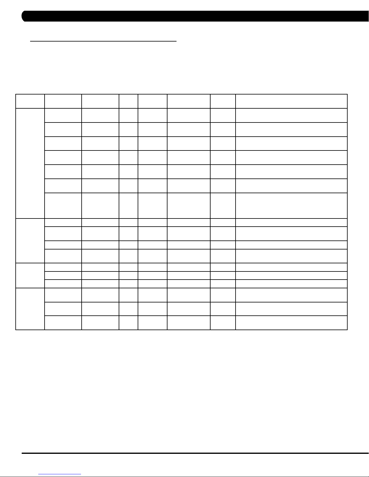
5.1 MANAGER MODE OVERVIEW
1) To enter Manager Mode, press number key "ENTER, 1, 0, 0, 1, ENTER" on the number keypad. Manager Mode will appear on the display.
2) To scroll through the list of options in Manager Mode, use the UP and DOWN LEVEL keys. Each of the custom settings will show on the display.
3) To select a custom setting, press the ENTER key when the desired setting is shown.
4) To change the value of the setting, use the UP and DOWN LEVEL keys.
5) To confirm and save the value of the setting, press the ENTER key.
6) To exit the setting without saving, press the BACK key.
7) Press and hold the STOP key for 3-5 seconds to return to normal operation.
Group Model Item1 Item2 Default
Workouts THURESAC
THURESAC
THURESAC Default Level 1 1~10 Starting resistance when GO is pressed or when
THURESAC
C Maximum
T
T
User THURESAC
HURESAC
T
THURESAC
THURESAC
Data &
T
ime
Speed THURESAC Unit Standard Standard/Metric This option sets speed unit is standard (Mile) or
THURESAC
HURESAC
T
THURESAC Time Zone 21 1~78 This option sets the time zone (See Table 1).
T
Maximum
T
ime
Default T
Pause T
Level
HRT Speed
Based
NAVY Test Site 0 0/1 0: Test site elevation less than 5000 ft above
Age 30 10-100 This option controls the default user's age.
W
Default Height 72/ 83 36/91~96/244 Default height of user
Gender Male Male/Femal Determines the gender of the user when not
Data 2015/01/01 This option sets the current date of the machine.
T
Max. 12.0/20.0 2.0/3.2~15.0/24.1 mph/kph Controls the maximum speed for all programs.
ime 20 4~MAX Minutes Workout time when GO is pressed or when no
ime 5:00 0:30/1:00/2:00/
eight 150lb/
ime RTC time This option sets the current time of the machine.
Value
60 4~99 Minutes Sets the total run time of any program.
20 10~25 Set the level which is the max usable speed.
OFF ON/OFF This option allows the user to choose speed
68kg
Values/Range Unit Notes
time is selected during program set up.
no resistance is selected during program set up.
3:00/4:00/5:00
50lb/23kg ~
400lb/182kg
Minutes :
Second
This option controls the default pause time.
based target heart rate programs.
sea level.
1: Test site elevation greater than 5000 ft
above sea level.
This option controls the default weight.
selected during program set up.
Metric.
.
T
Start 0.5/0.8 0.5/0.8~1.4/2.3 mph/kph Controls the starting speed for all programs
10
(does not affect minimum speeds).
Page 13

CHAPTER 5: MANAGER MODE
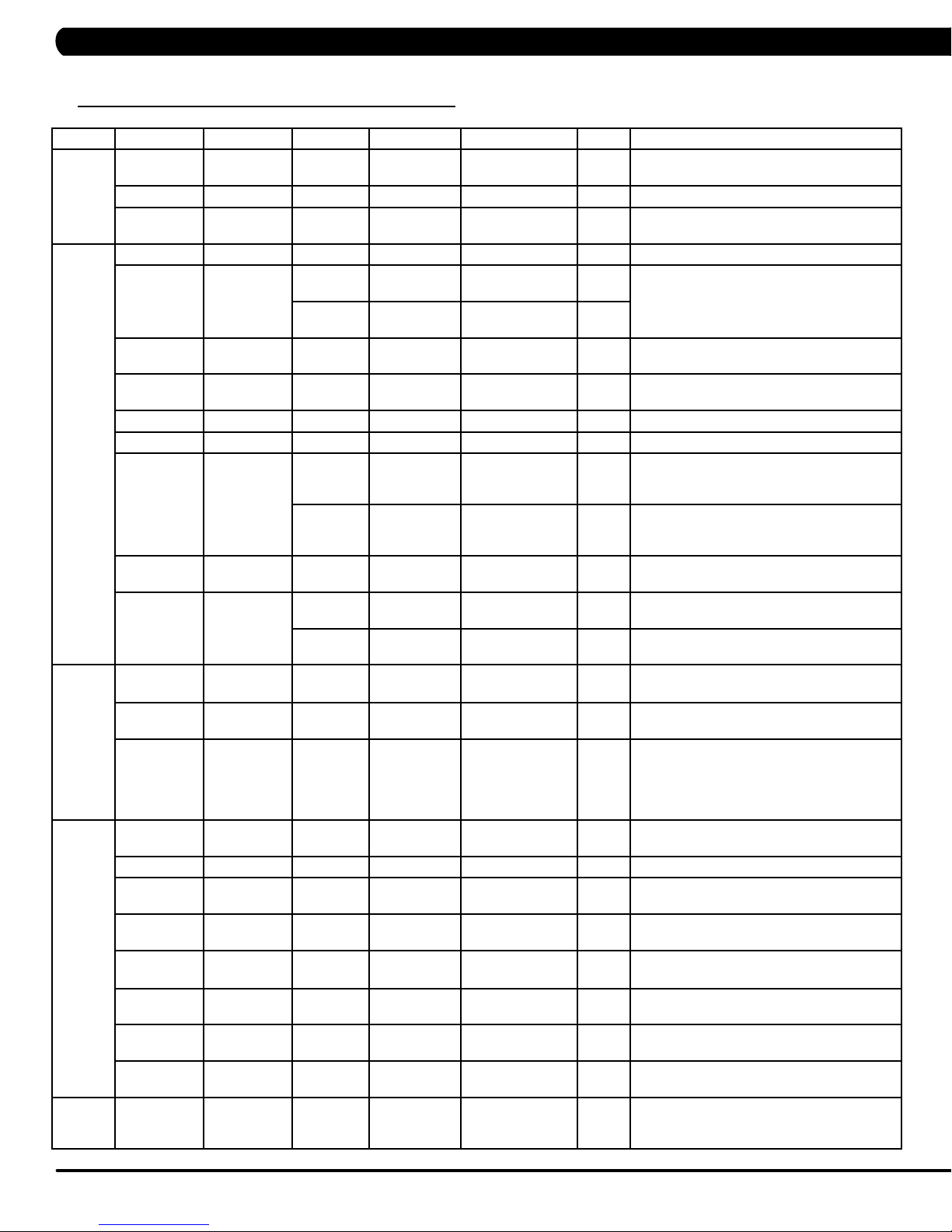
5.1 MANAGER MODE OVERVIEW
1) To enter Manager Mode, press number key "ENTER, 1, 0, 0, 1, ENTER" on the number keypad. Manager Mode will appear on the display.
2) To scroll through the list of options in Manager Mode, use the UP and DOWN LEVEL keys. Each of the custom settings will show on the display.
3) To select a custom setting, press the ENTER key when the desired setting is shown.
4) To change the value of the setting, use the UP and DOWN LEVEL keys.
5) To confirm and save the value of the setting, press the ENTER key.
6) To exit the setting without saving, press the BACK key.
7) Press and hold the STOP key for 3-5 seconds to return to normal operation.
Group Model Item1 Item2 Default
Elevation TA Max 15% 0.0% ~ 15% Controls the high incline parameter.
A Default 0%
A Reset This is a software feature that resets machine
Software THURESAC Version UCB Current software version of UCB.
LCB-MCUB Current software version of LCB-MCUB.
LCB-MCUA
(option)
Language Sets the language for the console.
WiFi Current software version of WiFi.
Bootloader Current software version of bootloader.
THURESAC Update UCB UCB software update.
LCB-MCUB LCB-MCUB software update.
LCB-MCUA
(option)
Language Language software update.
General
Language
THURESAC Auto Update Disable/
THUREA Accumulate
HURESAC Accumulate
SC Accumulate
THURESAC Default
THURESAC Erase
Distance
T
ime
Floors
Language
EEPROM
Enable
Time 1:00 AM HH:MM Set time that software automatically updates.
Check
Update
Value
Enable
0 0~999999 Mile/KmT
0 0~999999
0 0~999999 F
English Sets the language for the console. Select between
Values/Range Unit Notes
0%~Max
H
loors Total floors for all programs. Hold UP and DOWN
Starting incline level at each program start.
elevation to 0 degrees
after 30 seconds of user inactivity. During incline
reset, movement
can be stopped by pressing any console key. The
display will scroll
"HOLD SELECT TO RESUME." To resume reset
to 0 degrees, hold
the SELECT key for 3 seconds.
Current software version of LCB-MCUA.
LCB-MCUA software update.
This
update function is Disabled or Enabled.
Manually check remote update. Auto updating
console software from DAPI if it has the latest
version.
otal distance for all programs. Hold UP and
DOWN LEVEL keys for 3 seconds to clear record.
ours Total time for all programs displayed in hours.Hold
UP and DOWN LEVEL keys for 3 seconds to clear
record.
LEVEL keys for 3 seconds to clear record.
English, Spanish, German, Italian,
French, Dutch, Portuguese Swedish, Finnish,
urkish and Polish.
T
Erase language data in EEPROM.
option controls whether the auto software
11
Page 14
CHAPTER 5: MANAGER MODE
5.1 MANAGER MODE OVERVIEW - CONTINUED
Group Model Item1 Item2 Default Value Values/Range Unit Notes
Logo THURESAC
T
HURESAC
T
HURESAC
Machine T
TV T
Internet THURESAC Enable/
ErP Thuresac Erp T
HURESAC Type This option selects the current model.
THURESAC Serial
THURESAC
T T
THURESAC
THURESAC
THURESAC
HURESAC
T
THURESAC Keypad Stuck
HURESAC
THURESAC
THURESAC
T
HURESAC
T
HURESAC
THURESAC
T
HURESAC
T
HURESAC
THURESAC
T
HURESAC
Default Logo M
Import Logo Import logo from USB to console.
Erase
EEPROM
Number
Out of Order OFF ON/OFF This option allows the club to show the unit
read Sensor 30 30/60/90/OFF Tread Sensor function for user’s existence
Speaker OFF ON/OFF Sets console speaker sound on / of
Beeper ON ON/OFF Sets console beeper sound on / of
Headphone
Jack
USB Port Protection Enable Enable/Disable
Power OFF ON/OFF OFF:
Input Source OFF OFF/TV/PCTV/
Default
Volume
Disable
MAC ID MAC ID data.
IP Automatically detects the available IP
MODE
AP
Signal
Strength
Export
setting
to USB
Import setting
from USB
Reset Reset internet connected data. SSID/
ime OFF OFF~ 30
Console Prefix+(Type)
Frame Prefix+(Type)
Notification Enable Enable/Disable
Times to
waring
Check
Notification Enable Enable/Disable
OFF ON/OFF Sets whether console wireless module is
ATRIX
+YYMM00000
+YYMM00000
30000 1000~1000000
Enable Enable/Disable
(Current
Status)
YY-MM-xxxxx Serial Number input is available for both the
YY-MM-xxxxx
TV/CAB
Remote
Disconnected/25%
/50%/75%/100%
(Minutes)
This
screen header from a list.
Erase all logo data in EEPROM
Console and Frame.
Type: B~Z (A not display).
"out of order" if an error is present.
detect.
This
Jack insertion times warning function is
disabled or enabled.
This
headphone Jack insertion times before
warning function displays.
This
protection is disabled or enabled.
This
check is disabled or enabled.
This
overlay error notification is disabled or enabled.
ON: Don't turn off TV power after reset
Sets the audio of the console to the type of TV
attached.
a. Input default (DF: 15/Range1~15)
b. Max (DF: 32/ Range: 1~32)
c. Output Default (DF: 13/Range:1~Max)
Remote TV support a/b/c item, others only
support c.
Sets whether the internet function (WiFi) is
disabled or enabled.
and displays it.
an access point (AP) or not.
This option shows the current WiFi signal
strength.
Export internet setting (WiFi) to USB.
Import internet (WiFi) setting from USB.
password Factory Default Restore.
Minute Console will enter ErP mode if user does not
touch the screen or press any key pad for
couple minutes.
option allows the user to select the
f.
f.
option controls whether the headphone
option controls the number of
option controls whether the USB port
option controls whether the keypad stuck
option controls whether the Keypad/
Turn off TV power after reset
address
12
Page 15

CHAPTER 5: MANAGER MODE
5.1 MANAGER MODE OVERVIEW - CONTINUED
Table 1 - Time Zone list
Time Zone
Country Code Country Code Country Code Country Code
Asia/Kabul 1 America/Chicago 21 Asia/Jerusalem 41 Pacific/Apia 61
America/Anchorage 2 America/Monterrey 22 Asia/Seoul 42 Asia/Bangkok 62
Asia/Kuwait 3 Asia/Shanghai 23 Atlantic/South Georgia 43 Asia/Singapore 63
Asia/Muscat 4 Africa/Nairobi 24 America/Denver 44 Africa/Harare 64
Asia/Baghdad 5 Australia/Brisbane 25 America/Chihuahua 45 Asia/Colombo 65
America/Halifax 6 Europe/Minsk 26 Asia/Rangoon 46 Asia/Taipei 66
Australia/Darwin 7 America/Sao Paulo 27 Asia/Novosibirsk 47 Australia/Hobart 67
Australia/Sydney 8 America/New York 28 Africa/Windhoek 48 Asia/Tokyo 68
Asia/Baku 9 Africa/Cairo 29 Asia/Kathmandu 49 Pacific/Tongatapu 69
Atlantic/Azores 10 Asia/Yekaterinburg 30 Pacific/Auckland 50 America/Indianapolis 70
America/Edmonton 11 Pacific/Fiji 31 America/St Johns 51 America/Phoenix 71
Atlantic/Cape Verde 12 Europe/Riga 32 Asia/Irkutsk 52 Asia/Vladivostok 72
Asia/Yerevan 13 Asia/Tbilisi 33 Asia/Krasnoyarsk 53 Australia/Perth 73
Australia/Adelaide 14 Europe/London 34 America/Santiago 54 Africa/Lagos 74
America/Costa Rica 15 America/Godthab 35 America/Tijuana 55 Europe/Berlin 75
Asia/Almaty 16 Africa/Monrovia 36 Europe/Paris 56 Asia/Tashkent 76
America/Cuiaba 17 Europe/Istanbul 37 Europe/Moscow 57 Pacific/Guam 77
Europe/Belgrade 18 Pacific/Honolulu 38 America/Argentina/Buenos Aires 58 Asia/Yakutsk 78
Europe/Belgrade 19 Asia/Calcutta 39 America/Bogota 59
Pacific/Guadalcanal 20 Asia/Tehran 40 America/La Paz 60
13
Page 16
CHAPTER 6: ENGINEERING MODE
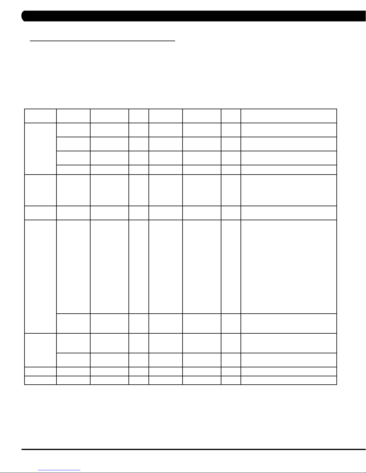
6.1 ENGINEERING MODE OVERVIEW
1) To enter Engineering Mode, press number key "ENTER, 2, 0, 0, 1, ENTER" on the number keypad. Engineer Mode will appear on the
display
.
2)
To scroll through the list of options in Engineering Mode, use the UP and DOWN LEVEL
display.
T
o select a custom setting, press the ENTER key when the desired setting is shown.
3)
To change the value of the setting, use the UP and DOWN LEVEL keys.
4)
5) To confirm and save the value of the setting, press the ENTER key
6)
To exit the setting without saving, press the BACK key
7) Press and hold the ST
Group Model Item1 Item2 Default Value Values/Range Unit Notes
OP key for 3-5 seconds to return to normal operation.
.
.
keys. Each of the custom settings will show on the
Calibration
Running
Test
Error Codes THURESAC Disable/Enable Enable Disable/Enable This option displays the error code history
DAPI
Safety C Setting 100 4~500 This option controls the safety threshold
Back Up
Motor T Type 0~2 This option selects the frame motor type
TA Auto
T Elevation Min This option controls the minimum elevation
T Elevation Max This option controls the maximum
A Elevation Tuner Original Incline Tuner of A5x
T This option allows installers to do the belt
THURESAC Server Production Dev/
THURESAC SSL ON ON/OFF This option controls the internet
C Switch ON->5
THURESAC To backup current software into EEPROM.
Calibration
X,
OFF->3X
QA/
Staging/
Production
ON/OFF The function of control zone is enabled or
This option is to calibrate the elevation
parameters.
parameter
elevation parameter
adjustment and test. Also this function will
not stop until press Stop or
exit the mode, it will provide customer for
demonstration and other functions.
on the unit.
Dev
unsecure domain: dev
SSL domain: dev-dls.jfit.co port: 443
QA
unsecure domain: qa.dls.jfit.co port: 80
SSL domain: qa-dls.jfit.co port 443
Staging
unsecure domain: staging.dls.jfit.co port:
80
SSL domain: staging-dls.jfit.co port 443
Production
unsecure domain: dapi-ls.jfit.co port: 80
SSL domain: dapi-ls.jfit.co port: 443
transmission with SSL
Layer) or not.
for the E-Stop function. of old control zone
(capacitance sensor).
disabled.
.
.
.dls.jfit.co port: 80
(Secure Sockets
14
Page 17

CHAPTER 7: SERVICE MODE/TEST MODE
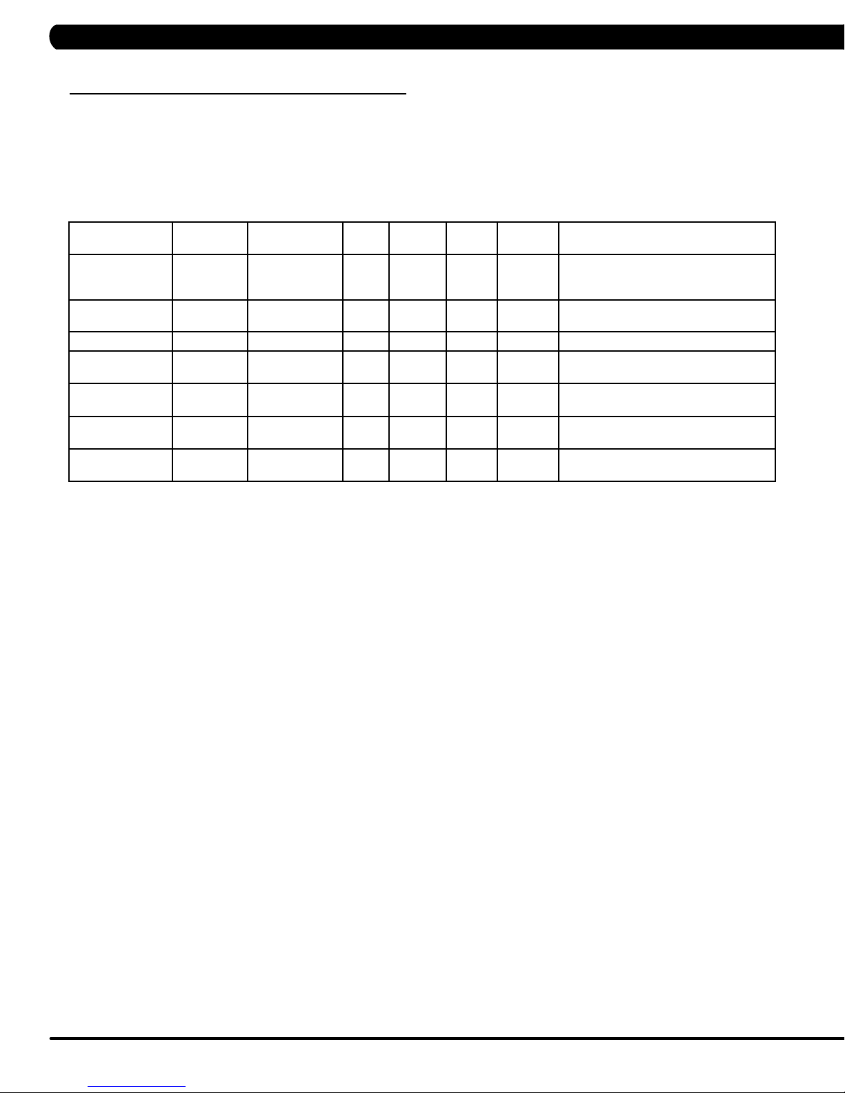
7.1 SERVICE MODE OVERVIEW
1) To enter Service Mode, press number key "ENTER, 3, 0, 0, 1, ENTER" on the number keypad. Engineer Mode will appear on the display.
2) To scroll through the list of options in Service Mode, use the UP and DOWN LEVEL keys. Each of the custom settings will show on the
display.
3) To select a custom setting, press the ENTER key when the desired setting is shown.
4) To change the value of the setting, use the UP and DOWN LEVEL keys.
5) To confirm and save the value of the setting, press the ENTER key.
6) To exit the setting without saving, press the BACK key.
Press and hold the STOP
7)
Group Model Item1 Item2 Default Value Values/Range Unit Notes
Accumulate
Log
Configuration
Factory Default
Asset
management
xID Login
THURESAC Distance Current value 0~999999 Mile/KmManually sets the Accumulated
THURESAC Time Current value 0~999999
SC Floors Current value 0~999999 Manually sets the Accumulated
THURESAC Error Display Error1~Error10
THURESAC Export to USB Export engineer parameters to
THURESAC Reset NO NO-YES Reset engineering default
THURESAC Disable/Enable Disable Disable/Enable
THURESAC Enable/Disable Disable Disable/Enable
key for 3-5 seconds to return to normal operation.
Distance.
Hour Manually sets the Accumulated
Time.
Floors.
/ None
Reset
Headphone Jack
Sensor
Import from USB Import engineer parameters
Club ID This option records the club ID
RFID link RFID card links with xID login
Insert Counts Current Value 0~999999
Reset NO NO-YES Reset headphone insert
NO NO-YES
Shows the last 10 errors.
Reset error log.
Insert headphone jack counts.
counts.
a USB device.
from a USB device.
to factory value.
This option controls
whether the AM function
is Disabled or Enabled.
of the fitness facility.
This option controls whether
the xID login function is
Disabled or Enabled.
data.
15
Page 18
CHAPTER 7: SERVICE MODE/TEST MODE
7.2 TEST MODE OVERVIEW
1) To enter Test Mode, press number key "ENTER, 5, 0, 0, 1, ENTER" on the number keypad. Engineer Mode will appear on the display.
2)
To scroll through the list of options in Test Mode, use the UP and DOWN LEVEL keys. Each of the custom settings will show on the display
o select a custom setting, press the ENTER key when the desired setting is shown.
3)
T
4)
To change the value of the setting, use the UP and DOWN LEVEL
To confirm and save the value of the setting, press the ENTER key
5)
To exit the setting without saving, press the BACK key.
6)
7) Press and hold the STOP key for 3-5 seconds to return to normal operation.
keys.
.
.
Group Model Item1 Item2 Default
Display
Keypad
C-SAFE
Headphone Jack
RFID Test
rP THURESAC
E
IR Frequency
CZ
THURESAC P
THURESAC Press any key and the display should
THURESAC P
THURESAC P
THURESAC Press the ENTER key to test RFID
Auto/5/10/30/60 Second Press the ENTER key and choice ErP
C Press the ENTER key to test IR sensor
Value
Values/
Range
Unit Notes
ress the ENTER key repeatedly to
check each set of LEDs on the display
sequentially.
show the corresponding message.
ress the ENTER key to test CSAFE.
ress the ENTER key to test the insert
headphone jack counts.
hardware and RFID card scan.
time to test ErP function.
frequency of control zone.
16
Page 19
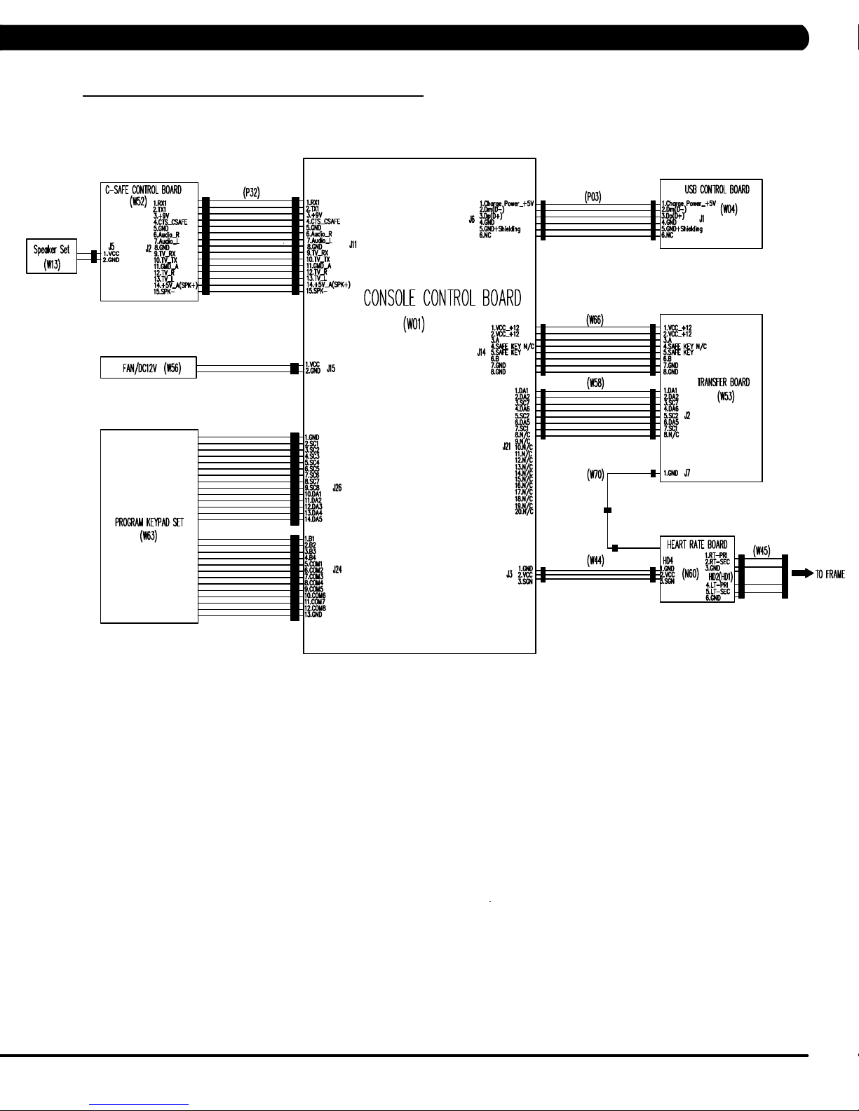
CHAPTER 8: TROUBLESHOOTING
8.1 ELECTRICAL DIAGRAMS
HURES5X-05/A5X-06-C ELECTRICAL BLOCK DIAGRAM
17
Page 20
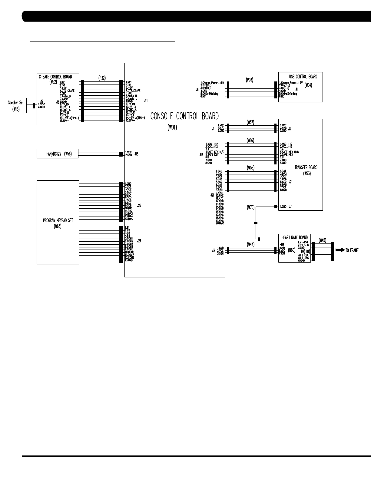
CHAPTER 8: TROUBLESHOOTING
8.1 ELECTRICAL DIAGRAMS - CONTINUED
C5X-03-C ELECTRICAL BLOCK DIAGRAM
18
Page 21
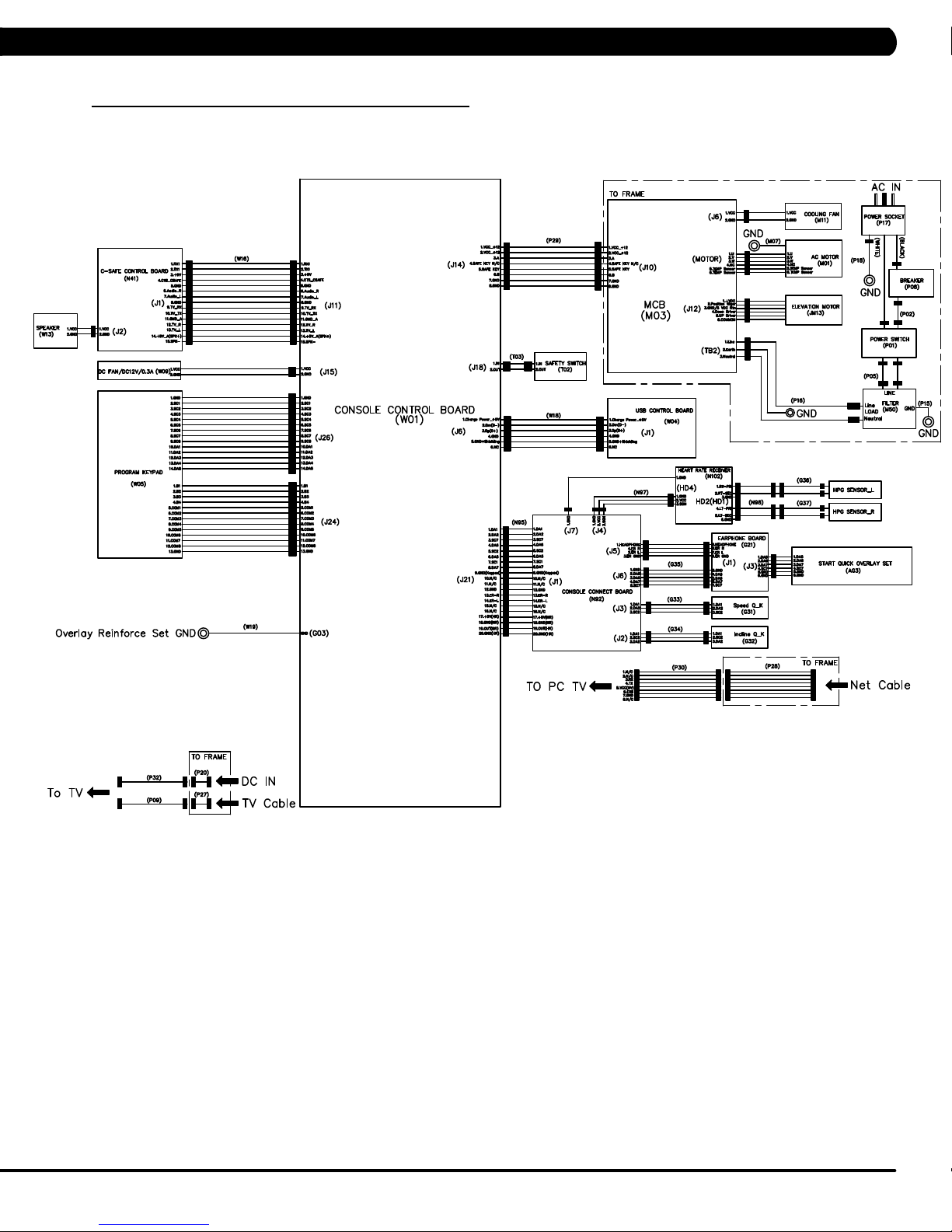
CHAPTER 8: TROUBLESHOOTING
8.1 ELECTRICAL DIAGRAMS
T5X-08-C ELECTRICAL BLOCK DIAGRAM
19
Page 22
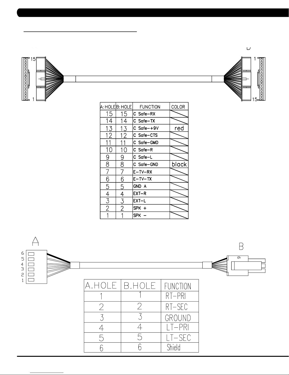
CHAPTER 8: TROUBLESHOOTING
8.1 ELECTRICAL DIAGRAMS - CONTINUED
C-SAFE+TV CONNECT WIRE (HURESAC5X-C)
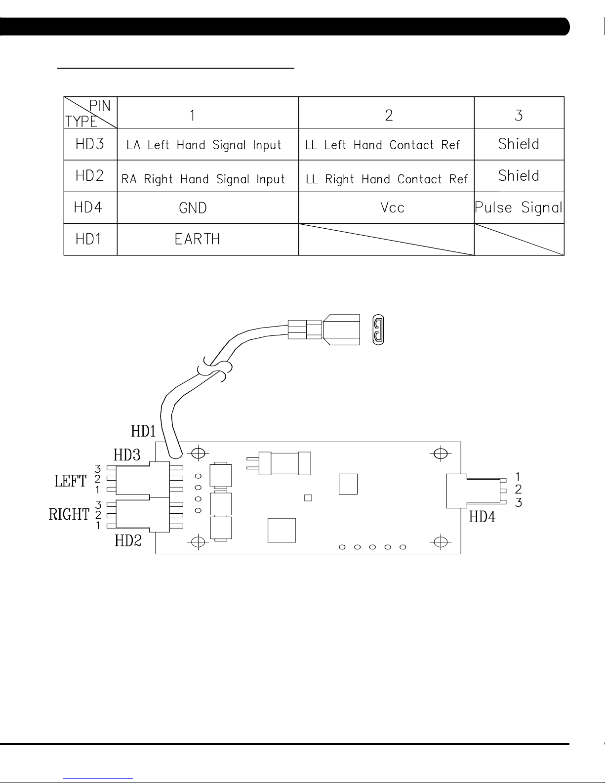
HAND PULSE WIRE (HURESAC5X-C)
20
Page 23
CHAPTER 8: TROUBLESHOOTING
8.1 ELECTRICAL DIAGRAMS - CONTINUED
PULSE BOARD SET (HURESAC5TX-C)
21
Page 24
CHAPTER 8: TROUBLESHOOTING
8.1 ELECTRICAL DIAGRAMS - CONTINUED
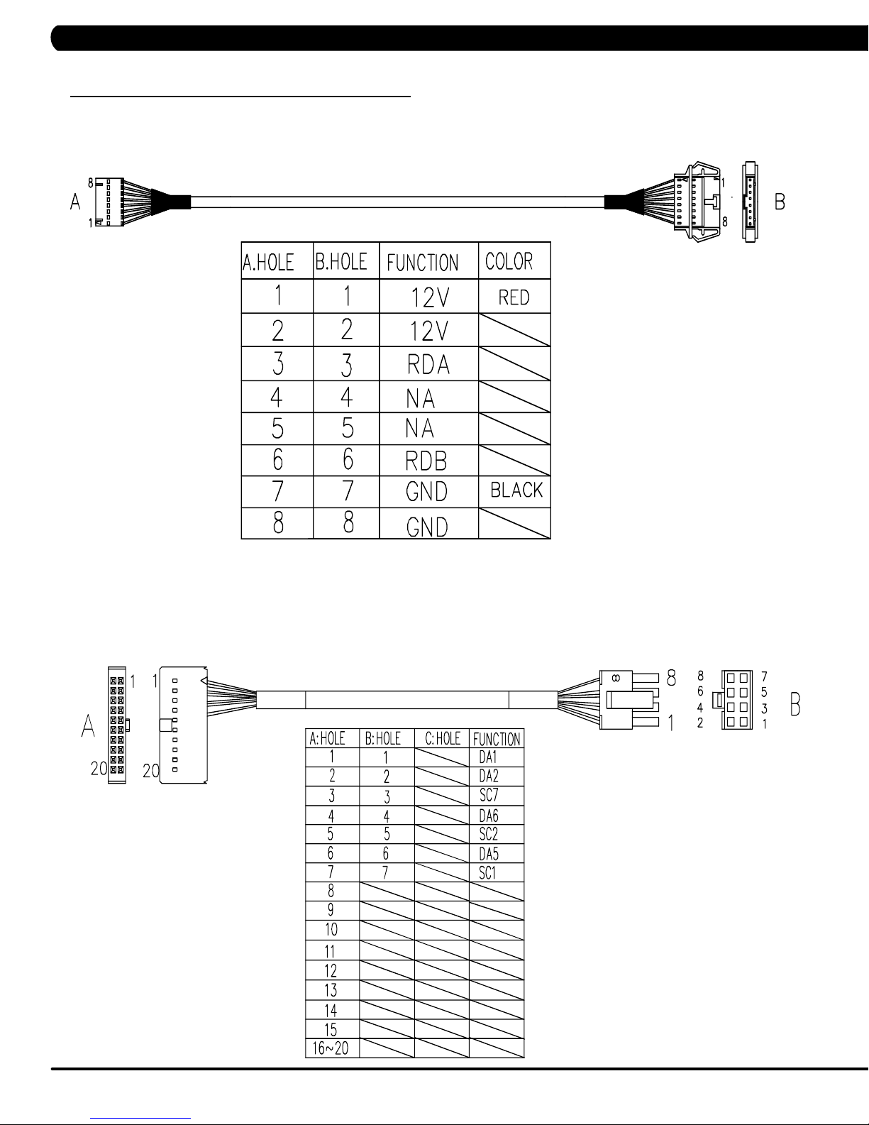
DIGITAL COMM WIRE (HURESAC5X-C)
QUICKLY KEY SET (HURESAC3X-C)
22
Page 25
CHAPTER 8: TROUBLESHOOTING
8.1 ELECTRICAL DIAGRAMS - CONTINUED
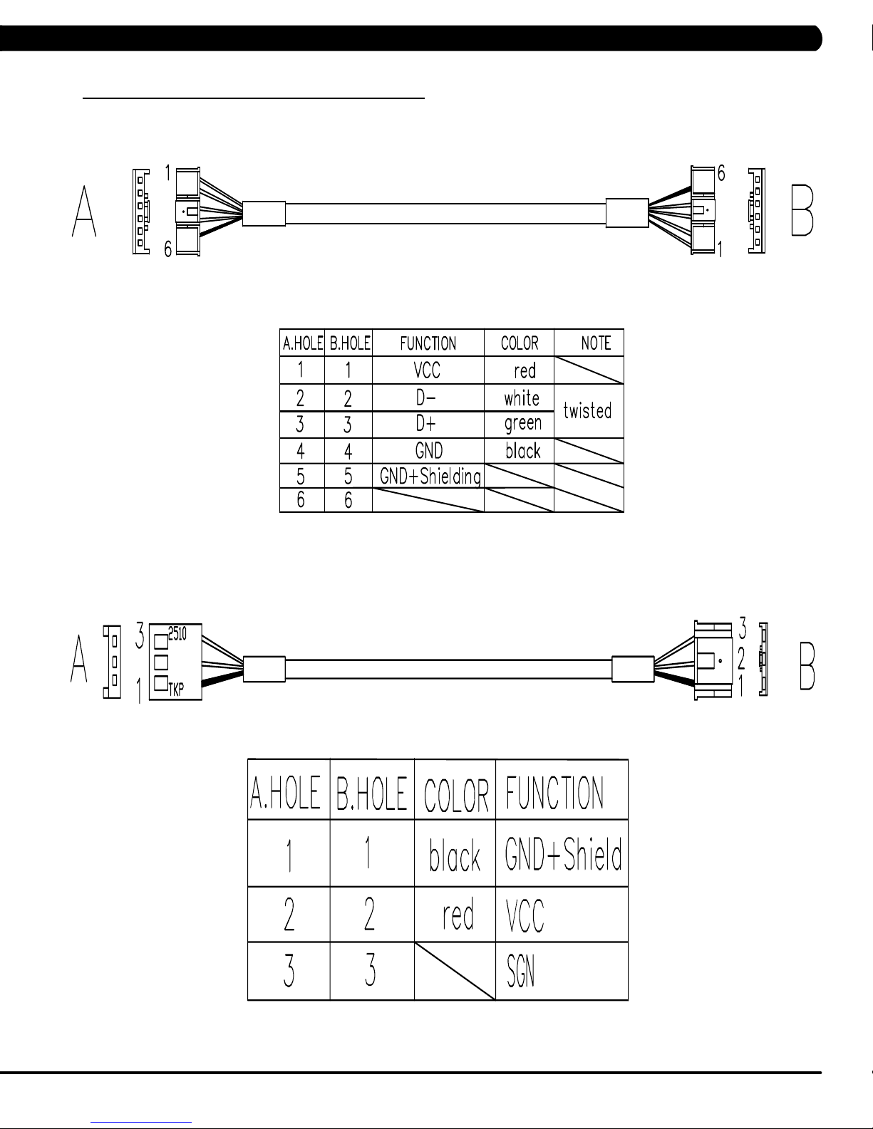
USB WIRE (HURESAC5X-C)
HEART RATE POWER WIRE (HURESAC5X-C)
23
Page 26

CHAPTER 8: TROUBLESHOOTING
8.1 ELECTRICAL DIAGRAMS - CONTINUED
PROGRAM KEYPAD (HURESA5X-C)
24
Page 27

CHAPTER 8: TROUBLESHOOTING
8.1 ELECTRICAL DIAGRAMS - CONTINUED
PROGRAM KEYPAD (C5X-C)
25
Page 28

CHAPTER 8: TROUBLESHOOTING
8.1 ELECTRICAL DIAGRAMS - CONTINUED
POWER WIRE (C5X-C)
UCB LITTLE BOARD WIRE (T5X-C)
26
Page 29

CHAPTER 8: TROUBLESHOOTING
8.1 ELECTRICAL DIAGRAMS - CONTINUED
PROGRAM KEYPAD- T5X
27
Page 30

CHAPTER 8: TROUBLESHOOTING
8.1 ELECTRICAL DIAGRAMS - CONTINUED
HAND PULSE SENSOR WIRE- T5X
SAFETY SWITCH WIRE- T5X
28
Page 31

CHAPTER 8: TROUBLESHOOTING
8.1 ELECTRICAL DIAGRAMS - CONTINUED
USB WIRE- T5X
29
Page 32

CHAPTER 8: TROUBLESHOOTING
8.2 ERROR CODES LIST
CODE CLASS DESCRIPTION MACHINE SOLUTION
It occurs when the calibration time is too long or the calibration distance is too
a.
short.
01A1 C Incline calibration error A
01A3 C Motor is disconnected T
01A8 C Main motor over current T
01AC C
01AF C
01B4 C
014A
(01AE)
0140 B Incline motor operation fail A
0141 B Motor over temperature T
0144 B Motor over current T
Electro magnet (ECB) over
current.
Electro magnet (ECB) dis
connected.
Resistance disconnect A
Electro magnet (ECB) disconnected.
Battery connection reverse
protection.
LCB charge current is
B
abnormal
-
HUR
C
HUR
C
AHUR
AHUR
b. Don’t fix the incline motor tube then turn on the power.
- If the console still shows 01A1, please replace incline motor.
- If auto calibration is finished, please follow the incline motor installation
SOP
c. Replace LCB.
a. Check the connection of the motor cable at the MCB.
b. Check the MCB LED DSP1 (MCU):
a.
Check the condition of the running deck and belt. Replace the belt and flip or
replace the running deck as needed.
Replace the MCB.
b.
a.
Check if the Electro-magnet is short circuited or open.
b. If the resistance data shows a short/open ohms or is outside the range of 12.8
~14.2 ohms, replace the Electro-magnet.
If the resistance data is in the range between 12.8 ~14.2 ohms, replace the LCB.
c.
On standby mode, measure the resistance on ECB1 and ECB2. Please check the
a.
ECB extension cable connection at the LCB (pins 1 & 3 for ECB1, pins 2 & 4 for
ECB2), there should be between 12.8 ~ 14.2 ohms.
-
-
Check the gap of ECB1 and ECB2. There should be a gap of .5mm between the
b.
ECB and the flywheel.
a.
Check if the Electro-magnet is short circuited or open.
b. If the resistance data shows a short/open ohms or is outside the range of 12.8
~14.2 ohms, replace the Electro-magnet.
If the resistance data is in the range between 12.8 ~14.2 ohms, replace the LCB.
c.
a.
Check if the resistance is short circuit.
- If resistance data is under 10 ohms, please replace power resistance.
- If resistance data is over 10 ohms, please replace LCB.
a.
Check the connection of the ECB extension cable from the LCB to the ECB.
Check to see if LED8 and LED10 on the LCB have a brief light for 3 second when
b.
you power on machine.
If the ECB resistance is within the range, replace the LCB.
c.
Check the battery wire connection between the battery and LCB.
a.
b. Check the battery voltage.
- If there is no data on voltage, replace the battery.
- If there is data on voltage, replace the LCB.
a. Replace LCB.
a. Please run A
b. If the error code happens in Auto Calibration, the machine still can work, no need
to do anything.
c. If the error code happens in workout, please replace the incline motor.
a.
Check the connection of the motor cable at the MCB.
b. Use a multi-meter to check the motor wire circuit. Set the multi-meter to Ohms
and place both terminals on the blue wires of the motor cable.
-
-
a.
Check the condition of the running deck and belt. Replace the belt and flip or
replace the running deck as needed.
b. Replace the MCB.
to fix incline motor
- If LED DSP1 is blinking or
- If LED DSP1 is not lit, replace the MCB.
If the ECB resistance is out of the range, replace the ECB.
If the ECB resistance is within the range, replace the LCB.
If LED8 and LED10 do not have a brief light, replace the LCB.
If LED8 and LED10 do have a brief light, check the ECB extension cable
connection at the LCB (pins 1 & 3 for ECB1, pins 2 & 4 for ECB2), there
should be between 12.8 ~ 14.2 ohms.
If the ECB resistance is out of the range, replace the ECB.
-
uto Calibration.
If there is an Ohm reading above 0, replace the motor
If the Ohm reading is 0, replace the MCB.
.
solid light, replace the motor
.
30
Page 33

CHAPTER 8: TROUBLESHOOTING
8.2 ERROR CODES LIST
CODE CLASS DESCRIPTION MACHINE SOLUTION
a. Please check the incline motor wire connection between the incline
and LCB.
A
0147 B Incline motor disconnection
T
0148
(01A7)
0149 B
02AB C Machine type error. ESHURA
02AD C MCB is over temperature T
02A0 C Encoder error C
02A2 C Over DC bus voltage T
02A3 C
02A7 C
02BA C
02BB C
02BC C
02BD C
02BE C DC brake error. C
02BF C DC brake Over Current C
B Incline motor over current. A
The resistance current is
over
Low AC power input voltage
when motor running
over I rms of phase current
of motor
The inner memory IC data
read error.
Inverter hardware interrupts
error.
Ground connection or fuse
error
Drive hardware interrupt
error.
A
T
T
T
T
T
T
b. Please check the incline motor VR if there’s data.
- If there’s no data, replace the incline.
- If there’s data, replace the LCB.
a. Please check the incline motor wire connection between the incline
and MCB.
b. Run auto calibration.
c. If the issue is not solved by replacing the incline motor.
a. Don’t fix the incline motor tube then turn on the power.
- If the console still shows error, please replace incline motor.
- If the console does not show error, please follow the incline
motor installation SOP to fix incline motor.
b. Replace LCB.
a. Please check if the resistance is short circuit.
- If resistance data is under 10 ohms, please replace power
resistance.
- If resistance data is over 10 ohms, please replace LCB.
a. Change the machine type on the console to match the correct
frame
a. Check if that both fans are operating (there is a fan mounted to the
MCB itself as well as an external fan). Also check the connection
of the fans at the MCB.
b. If the fans are running correctly, replace the MCB.
a. Check the connection of the speed sensor cable from the LCB to
the speed sensor.
b. Check to see if LED D35 on the LCB is on when the brake is
turned to the left release position.
c. If LED D35 is off, move the stairs about 3 stairs and check to see
if LED D35 is flashing.
- If not, replace the speed sensor.
- If yes, adjust the speed sensor position and clean the speed
sensor of any debris then re-test.
a. Please check if the input power is normal(110V : over 140V/ 220V:
over 280V)
b. Replace the MCB.
a. Please check if the input power is normal(110V : low 76V/ 220V:
low 186V)
b. Replace the MCB.
a. Please check the Motor wire connection between the Motor and
MCB.
b. Please use the electric meter to check the 3 points (U/V/W) and
see if there’s data of inside impedance.
- If yes, replace MCB.
- If no, replace Motor set.
a. Reboot power, if error shows again, replace the MCB.
b. Reboot power, if error shows again, replace the MCB.
a. Check the Motor wire (3 points U/V/W) and ground wire whether
short
b. Replace the MCB.
a. Replace MCB.
a. Check the power extend wire connection between the brake and
LCB for any damage.
b. Check to see if the stairs will move when you are in the stop posi-
tion. If yes, replace the brake.
a. Check the power extend wire connection between the brake and
LCB for any damage.
b. Check to see if the stairs will move when you are in the stop posi-
tion. If yes, replace the brake.
31
Page 34

CHAPTER 8: TROUBLESHOOTING
8.2 ERROR CODES LIST - CONTINUED
CODE CLASS DESCRIPTION MACHINE SOLUTION
a. Check the connection of the safety key (emergency stop) switch. If the
02B2 C Safe key action response T
02B4 C Resistance Type Error. ESHURA
02B5 C
02B6 C Speed up have over current. T
02B7 C Speed down is overcurrent. T
02B8 C Running status is overcurrent T
02B9 C
02C0 C DC brake in manual mode. C
02C1 C Speed tracking error C
02C2 C
02C3 C Frame IR sensor error C
02C4 C
02C5 C
02C6 C
02C7 C
0201 A LCB battery low voltage. ESA a. Plug in the machine to charge battery for 24 hours.
0247 B LCB fail ESHURA a. Replace LCB.
0248 B
Inverter sensor the normal
rated current over 150% ,
can hold 60 sec.
The inner memory IC data
write error.
CZ 3IR sensors have no
communication or disconnected over 3 seconds.
The frequency error form
control zone.
The frequency error for frame
IR sensor.
The receiver disconnection
for control zone.
The receiver disconnection
for frame IR sensor
Battery disconnection or
fail ( LCB battery voltage is
less than 6 volts ).
T
T
C
C
C
C
C
ESHURA
switch is always open or shorted out, replace the switch.
b. If the emergency stop does not resolve the issue, replace the
a. Make sure machine type is set for the correct frame in console.
- If yes, replace LCB.
- If no, change to correct type and reboot the power.
a. Replace MCB.
a. Check the condition of the running deck and belt. Replace the belt and
flip or replace the running deck as needed.
b. Replace the MCB.
a. Check the condition of the running deck and belt. Replace the belt and
flip or replace the running deck as needed.
b. Replace the MCB.
a. Check the condition of the running deck and belt. Replace the belt and
flip or replace the running deck as needed.
b. Replace the MCB.
a. Reboot power, if error shows again, replace the MCB.
a. Check if the DC brake is in the Right “lock" position. Release the brake
(move to the left) if in lock position.
b. Replace the brake.
a. Adjust the speed sensor position and clean the speed sensor of any
debris.
b. Check the ECB extension cable connection at the LCB (pins 1 & 3
for ECB1, pins 2 & 4 for ECB2), there should be between 12.8 ~ 14.2
ohms, check which ECB is outside the range and replace it.
a. Check if there’s something blocking the control zone 3 IR sensors.
b. Check if the control zone 3IR sensors (transmitter and receiver) are
aligned.
c. Check the connection of the control zone extension cable from the
transmission board to the receiver board.
d. Replace the transmission board or control zone extension cable as
needed.
a. Check if there’s something blocking the frame IR sensors.
b. Check if the frame IR sensors (transmitter and receiver) are aligned.
c. Check the connection of the frame IR transmitter cable from the LCB
to the frame IR transmitter sensors.
d. Replace the frame IR transmitter cable if the cable is defective.
a. Replace the control zone transmission board or receiver board.
a. Replace LCB
a. Check the connection of the control zone extension cable from the
LCB to the control zone.
b. Replace the receiver board.
a. Check the connection of the frame IR receiver cable from the LCB to
the frame IR receiver sensor.
b. Replace the frame IR receiver cable.
a. Check battery wire connection to LCB.
b. Check to see if the battery voltage is less than 6 volt.
- If less than 6 volt, replace battery.
- If not, replace LCB.
UCB.
32
Page 35

CHAPTER 8: TROUBLESHOOTING
8.2 ERROR CODES LIST - CONTINUED
CODE CLASS DESCRIPTION MACHINE SOLUTION
03A5 C Failed to load program Console a. Replace
03A6 C Failed to run program Console a. Replace UCB
03A8 C Machine type error ESHURACT
0301 A Memory block damage Console a. Enter the Engineer mode disable B Level Error, by pass
0302 A UCB low battery voltage Console a. Enter the Engineer mode disable B Level Error, by pass
0303 A UCB low supply voltage Console a. Enter the Engineer mode disable B Level Error, by pass
0304 A Earphone Board Need
0305 A USB Hardware OT or OC Console a. Enter the Engineer mode disable B Level Error, by pass
0306 A Keypad press keep 60 sec-
0340 B Key pad in extraordinary
0341 B Fan over current Console a. Enter the Engineer mode disable B Level Error, by pass
0343 B UCB Over supply voltage Console a. Enter the Engineer mode disable B Level Error, by pass
0345 B Correct packet but LCB with-
0346 B UCB detect the error of LCB
0347 B VA Load program fail. Console a. Enter the Engineer mode disable B Level Error, by pass
0348 B Motor not to run. Console a. Enter the Engineer mode disable B Level Error, by pass
04A0 C
04B0 C
04B1 C
Replace
onds
operation
out the function
incline position error
If LCB have no message to
return UCB over 3 seconds
UCB not have communication response
IO board not have communication response.
Console a. Enter the Engineer mode disable B Level Error, by pass
Console a. Enter the Engineer mode disable B Level Error, by pass
Console a. Enter the Engineer mode disable B Level Error, by pass
Console a. Enter the Engineer mode disable B Level Error, by pass
Console a. Enter the Engineer mode disable B Level Error, by pass
Communication
Errors
Communication
Errors
Communication
Errors
a. Change the correct machine type in the console and reboot
power again.
CLASS A and B error code.
b. Replace
CLASS A and B error code.
b. Replace battery
CLASS A and B error code.
b. Make sure the RPM over 35, when the machine of self-power
mode
CLASS A and B error code.
b. Replace Earphone Board
CLASS A and B error code.
b. Replace
CLASS A and B error code.
b. Replace Keypad
CLASS A and B error code.
b. Replace Keypad
CLASS A and B error code.
b. Replace Fan
CLASS A and B error code.
b. Check the LCB provide power whether over 13 voltage
If yes, replace LCB
If not, replace
CLASS A and B error code.
b. Replace
CLASS A and B error code.
b. Running the incline motor calibration again
CLASS A and B error code.
b. Replace VA Micro SD card
CLASS A and B error code.
b. Replace
a. Check the connection of the console cable at both ends and
perform continuity test.
b. Replace LCB
a. Check the connection of the console cable at both ends and
perform continuity test.
b. Replace
a. Replace UCB
UCB
UCB
UCB
UCB
UCB
UCB
UCB
33
Page 36

CHAPTER 8: TROUBLESHOOTING
8.2 ERROR CODE LIST - CONTINUED
CODE CLASS DESCRIPTION MACHINE SOLUTION
Enter the Engineer mode disable B Level Error, by pass CLASS
a.
A
0440 B Timeout receive packet
0441 B
0442 B
When UCB implements a
command, LCB has no this
command.
the received command code
from the console is correct
and is supported, but it has
less or more data arguments
Communication
Errors
Communication
Errors
Communication
Errors
and B error code
b.
Check the connection of the console cable at both ends and perform continuity test.
Replace LCB
c.
a. Enter the Engineer mode disable B Level Error
a.
a. Enter the Engineer mode disable B Level Error, by pass CLASS
A and B error code
CLASS
A
and B error code.
, by pass
34
Page 37

CHAPTER 9: PARTS REPLACEMENT GUIDE
9.1 CONSOLE REPLACEMENT
1) Remove the 5 screws holding the console to the frame (Figure A).
2) Disconnect the console cable, ground cable and HR connections from the defective console and remove the console (Figure B).
e.g. HUR5X console
FIGURE A FIGURE B
--For A/E 5x console only
2.1) Remove the 5 screws that hold the mounting plate to the console (Figure C).
2.2) Attach the mounting plate to the new console.
FIGURE C
3) Reinstall the wire connections to the new console.
4) Carefully push the wires into the console and mast until they are clear of the console / mast connection and attach the console to the mast
using the 5 screws.
5) T
est the unit for function as outlined in Section 9.3.
35
Page 38

CHAPTER 9: PARTS REPLACEMENT GUIDE
9.2 CONSOLE KEYPAD/OVERLAY REPLACEMENT
1) Remove the console as outlined in Section 9.1.
2) Remove the 6 screws holding on the back cover of the console and remove it (Figure A).
3) Unplug the faulty keypad from the UCB - 2 ribbon cables for program (Figure B).
FIGURE A
FI
GURE B
4) Use a
5) Clean the console area with alcohol to remove any leftover adhesive (Figure D).
razor to remove the faulty keypad / overlay from the console faceplate (Figure C).
FIGURE C
6) Peel the backing off of the new keypad (Figure E).
7) Slide the ribbon cables through the slots in the console faceplate (Figure F).
FIGURE D
36
FIGURE FFIGURE E
Page 39

CHAPTER 9: PARTS REPLACEMENT GUIDE
9.2 CONSOLE KEYPAD/OVERLAY REPLACEMENT - CONTINUED
8) Plug the ribbon cables into the UCB (Figures G).
9) Carefully line up the new keypad to the outline in the console faceplate (Figure H).
FIGURE G
10) Peel the backing off of the new overlay (Figure I).
11) Carefully line up the new overlay to the outline in the console faceplate. Once it is in place, press down on the overlay so that the adhesive
on the overlay bonds to the keypad (Figure J).
FIGURE H
FIGURE JFIGURE I
12) Reverse Steps 1-2 to re-assemble the console.
13)
T
est the unit for function as outlined in Section 9.3.
37
Page 40

CHAPTER 9: PARTS REPLACEMENT GUIDE
9.3 TESTING THE UNIT
ONCE THE UNIT OR REPLACEMENT PART IS FULLY INSTALLED AND ASSEMBLED AND
PR
OPERLY PLACED ON THE FLOOR, USE THE FOLLOWING INSTRUCTIONS T
ND TEST THE MACHINE:
A
O SE
TUP
--For H/U/R/E/S/A5X-C
1) Enter Manager Mode and input the serial number of the console and frame. Also set the Machine Type and verify
are correct.
2) If the unit has an add-on TV, program the channels (see Entertainment Owner's Manual).
3) Without hitting start or entering any program modes, step on the pedals and hold the handlebars while initiating movement to simulate
exercising. While moving, listen for any odd noises or squeaks.
4) After stopping movement, press the green GO key and begin pedaling.
5) Grasp the hand grips to check for proper heart rate response.
6) Press the level up and down buttons on the console and hand grips to make sure resistance is fully functional.
7) If everything functions properly, stop pedaling and the unit will reset to normal operation within 30 seconds.
For C5X-C
--
1) To enter Manager Mode, press number key "ENTER, 1, 0, 0, 1, ENTER" on the number keypad. Input the serial number of the console. Also
set the Machine Type and verify that the Date and Time are correct.
2) Press the green GO key and begin using the machine. Stand on the machine and hold the handlebars while initiating movement to simulate
exercising. While moving, listen for any odd noises or squeaks.
3) Grasp the hand grips to check for proper heart rate response.
4) Press the level up and down buttons on the console to make sure resistance is fully functional.
5) Try stepping off the unit to make sure the proximity sensor is fully functional. Also test the STOP key on the grips, IR sensor for function.
that the Date and Time
38
Page 41

CHAPTER 10: SPECIFICATIONS AND ASSEMBLY GUIDE
10.1 WIFI INSTALLATION
HURESACT5X WIFI Installation
MAIN COMPONENT LIST OF WIFI SET (PART NUMBER #1000366472)
Item Parts number Description Q’ty
1 1000385415 Control Board;;;HF-A11-0;V2.049;;; 1
1.1 1000385417 Control Board;;;V5.0;V2.049;;HF-A11-0; 1
1.2 1000385418
1.3 1000385725 Foam Tap;;;41x11;;3M 4945; 1
2 0000086721 SCREW;RND;M2X0.5PX6L;;PH;;BZN;; 2
3 1000309516 Tape;;;40x10x0.2;;EP614 1
WIFI Aerial;;;;;NB098-2400300PEX;;HF-A1
1
39
Page 42

CHAPTER 10: SPECIFICATIONS AND ASSEMBLY GUIDE
10.1 WIFI INSTALLATION - CONTINUED
10.1.1 HURESAC5X WIFI Installation
1) Plug in the WiFi board (item #1.1 in the table) to the UCB and use the 2 screws (item #2 in the table) to fix it (Figure A).
2) Stick the foam tape (item #1.3 in the table) on the front cover (Figure B).
FI
FIGURE A
GURE B
3) Stick the WiFi aerial board (item #1.2 in the table) to foam tape and connect the signal wire to WiFi board (Figure C).
4) Use tape (item #3 in the table) to fix the signal connecting wire to the front cover of the console (Figure D).
FIGURE C
FIGURE D
40
Page 43

CHAPTER 10: SPECIFICATIONS AND ASSEMBLY GUIDE
10.1 WIFI INSTALLATION - CONTINUED
10.1.2 T5X WIFI Installation
1) Plug in the WiFi board (item #1.1 in the table) to the UCB and use the 2 screws (item #2 in the table) to fix it (Figure A).
2)
Stick the foam tape (item #1.3 in the table) on the front cover (Figure B).
FIGURE A FIGURE B
3) Stick the WiFi
4) Use tape (item #3 in the table) to fix the signal connecting wire to the front cover of the console (Figure D).
aerial board (item #1.2 in the table) to foam tape and connect the signal wire to WiFi board (Figure C).
FIGURE C
FIGURE D
41
Page 44

CHAPTER 10: SPECIFICATIONS AND ASSEMBLY GUIDE
10.1 WIFI INSTALLATION - CONTINUED
10.1.3 How to set up the “WIFI” function
1. Create a WiFi config file
Step 1: Use your computer and use "note" function to create a wifi config file ( the name is called 'wifi_set.cfg’ - Figure A).
Step 2: Check your
completed, put the 'wifi_set.cfg' file to USB flash drive (the access should read \MA
AP data and modifying SSID & Key (password) required by facility
Access Point (AP) to 'wifi_set.cfg' files. Once this is
TRIX\FW\ - Figure B).
FIGURE BFIGURE A
2. Install WiFi config software for WiFi connection.
Step 1: Insert USB driver with ‘wifi_set.cfg’
Step 2: Enter Manager Mode by pressing ‘enter
Step 3: Press the Level UP
Step 4: Pres Enter key to enter Enable/Disable setup (Figure E).
Step 5: Use the Level UP
and DOWN keys to select “Internet” and press Enter Key to enter
and DOWN keys to select "Enable" (Figure F).
file to console (Figure C).
, 1, 0, 0, 1, enter’.
(Figure D).
FIGURE DFIGURE C
42
FIGURE FFIGURE E
Page 45

CHAPTER 10: SPECIFICATIONS AND ASSEMBLY GUIDE
10.1 WIFI INSTALLATION - CONTINUED
10.1.3 How to set up the “WIFI” function - continued
3. Install WiFi config software for WiFi connection - continued
Step 6: Press the <- key on the number keypad to back. Use the Level UP and DOWN keys to select "Import Setting" (Figure G).
Step 7: Press enter key to start wifi installation process (Figure H).
FIGURE HFIGURE G
Step 8: When the message shows “Success !!" in a short time, it means the update is completed (Figure I).
FIGURE I
4. Console WiFi function test
Step 1: Enter Manager mode-> Internet -> MAC ID (Figure A).
Step 2: If WiFi Module was installed correctly, the screen will show the MAC ID data (Figure B).
FIGURE BFIGURE A
43
Page 46

CHAPTER 10: SPECIFICATIONS AND ASSEMBLY GUIDE
10.1 WIFI INSTALLATION - CONTINUED
10.1.3 How to set up the “WIFI” function - continued
4. Console WiFi function test - continued
Step 3: Enter Manager mode-> Internet -> Signal Strength (Figure C). See if the wireless signal strength is OK (Figure D).
Note: For wireless connection quality
, the stable signal strength of wireless is necessary.
FIGURE DFIGURE C
Step 4: Enter Manager mode-> Internet -> IP (Figure E).
Step 5: If WiFi module was connected with AP, the screen will show the IP address (Figure F).
FIGURE FFIGURE E
44
Page 47

CHAPTER 10: SPECIFICATIONS AND ASSEMBLY GUIDE
10.2 RFID INSTALLATION
10.2.1 HURESAC5X RFID Installation
Note: For the HURESAC5x RFID installation first time, you must order and install WiFi set (part number
#1000366472) and RFID set (part number #1000364289) at the same time. The SAP # for the WIFI + RFID kit
is 1000390566.
WIFI + RFID kit SAP no.
Including kit
Item Parts number Description
1 1000366472
WiFi set
1000390566.
2 1000364289 RFID set
MAIN COMPONENT LIST OF RFID SET (PART NUMBER #1000364289)
Item Parts number Description Q’ ty
1 1000355790 Reader;;;GAT-RM310 3.0;V3.1.1.0/V1.2;;EP 1
2 004350-AB SCREW;BH;M3X0.5PX6L;;PH;;;;BP 2
3 1000355791 Antenna board;;;GAT-MAXI LA 3.0;;;EP614C; 1
4 1000364547 Ferrite Plate Absorber;;K5B,FT 10x1.0x10 1
5 1000204284 TAPE;FOAM;SINGLESIDE;15x30x4T; 2
6 1000364292 Signal CONN;;;;;;;500(IPEX,MHF37+JST,ZHR 1
7 1000309516 Tape;;;40x10x0.2;;EP614 4
8 1000363661 Fixing Bracket;;;ABS PA746;BL/Black C;;; 1
9 008864-A Screw; Round Head;Φ2.9x1.06Px7L;Hi/Lo Thr 2
45
Page 48

CHAPTER 10: SPECIFICATIONS AND ASSEMBLY GUIDE
10.2 RFID INSTALLATION - CONTINUED
10.2.1 HURESAC5x RFID Installation (continued)
1. Stick the foam tape (item #5 in the table) on the UCB as marked in yellow (Figure A).
FIGURE A
2. Stick the absorber (item #4 in the table ) on the reader board as marked in yellow (Figure B).
3. Plug in the Reader board to the UCB and use the 2 screws (item
#2 in the table) to fix it (Figure C).
FIGURE CFIGURE B
4. Put the antenna board on the front cover of the console. Connect the signal connecting wire (item #3/6 in the table) to antenna board (Figure
D).
5. Put the fixing bracket (item #8 in the table) on the antenna board. Use the two screws to fix it. (Figure E).
FIGURE D
46
FIGURE E
Page 49

CHAPTER 10: SPECIFICATIONS AND ASSEMBLY GUIDE
10.2 RFID INSTALLATION - CONTINUED
10.2.1 HURESAC5x RFID Installation (continued)
6. Connect the Signal connected wire to J8 of UCB (Figure F).
7. Use tape (item #7 in the table) to fix the signal connecting wire to the front cover of the console (Figure G).
FIGURE GFIGURE F
47
Page 50

CHAPTER 10: SPECIFICATIONS AND ASSEMBLY GUIDE
10.2 RFID INSTALLATION - CONTINUED
10.2.2 T5X RFID Installation
NOTE: For the T5x RFID function used, you must order and install WiFi set (part number #1000366472) and
RFID set (part number #1000364291) at the same time. The SAP # for the WIFI + RFID kit is 1000390648.
WIFI + RFID kit SAP no.
Including kit
Item Parts number Description
1 1000366472
WiFi set
1000390648
2 1000364291 RFID set
MAIN COMPONENT LIST OF RFID SET (PART NUMBER #1000364291)
Item Parts number Description Q’ ty
1 1000355790 Reader;;;GAT-RM310 3.0;V3.1.1.0/V1.2;;EP 1
2 004350-AB SCREW;BH;M3X0.5PX6L;;PH;;;;BP 2
3 1000355791 Antenna board;;;GAT-MAXI LA 3.0;;;EP614C; 1
4 1000364547 Ferrite Plate Absorber;;K5B,FT 10x1.0x10 1
5 1000204284 TAPE;FOAM;SINGLESIDE;15x30x4T; 2
6 1000364292 Signal CONN;;;;;;;500(IPEX,MHF37+JST,ZHR 1
7 1000309516 Tape;;;40x10x0.2;;EP614
8 1000356734 Fixing Bracket;;;PA746;BL/Black C;;TM521
9 008864-A Screw;Round Head;Φ2.9x1.06Px7L;Hi/Lo Thr 3
48
4
1
Page 51

CHAPTER 10: SPECIFICATIONS AND ASSEMBLY GUIDE
10.2 RFID INSTALLATION - CONTINUED
10.2.2 T5x RFID Installation (continued)
1. Stick the foam tape (item #5 in the table) on the UCB as marked in yellow (Figure A).
FIGURE A
2. Stick the absorber (item #4 in the table) on the reader board as marked in yellow (Figure B).
3. Plug in the Reader board to the UCB and use the 2 screws (item
#2 in the table) to fix it (Figure C).
FIGURE CFIGURE B
4. Put the antenna board on the front cover of the console. Connect the signal connecting wire (item #3/6 in the table) to antenna board (Figure
D).
5. Put the fixing bracket (item #8 in the table) on the antenna board. Use the three screws to fix it (Figure E).
FIGURE D
FIGURE E
49
Page 52

CHAPTER 10: SPECIFICATIONS AND ASSEMBLY GUIDE
10.2 RFID INSTALLATION - CONTINUED
10.2.2 T5x RFID Installation (continued)
6. Connect the Signal connected wire to J8 of UCB (Figure F).
7. Use tape (item #7 in the table) to fix the signal connecting wire to the front cover of the console (Figure G).
FIGURE GFIGURE F
50
Page 53

CHAPTER 10: SPECIFICATIONS AND ASSEMBLY GUIDE
10.2 RFID INSTALLATION - CONTINUED
10.2.3 How to set up the “RFID” function
O
nce the RFID set has been installed, the xID function must be enabled first then RFID can be used.
1. Enable "xID" function
Step 1: Enter Service Mode by pressing “enter, 3, 0, 0, 1, enter”.
Step 2: Select “xID Login” (Figure
Step 3: Select “Enable” (Figure B).
Step 4: Enter Engineering Mode by pressing “enter
Step 5: Select “DAPI” (Figure C).
Step 6: Select “Server” (Figure D).
Step 7: Select “Production” (Figure E).
A).
, 2, 0, 0, 1, enter”.
FIGURE BFIGURE A
FIGURE DFIGURE C
FIGURE E
51
Page 54

CHAPTER 10: SPECIFICATIONS AND ASSEMBLY GUIDE
10.2 RFID INSTALLATION - CONTINUED
10.2.3 How to set up the “RFID” function (continued)
2. RFID hardware function test in Test mode and home screen
In TEST mode:
Step 1: Enter Test Mode by pressing ‘enter, 5, 0, 0, 1, enter’.
Step 2: Select “RFID” test (Figure A). Pres Enter to enter RFID card scan (Figure B).
Step 3: Put your wristband near RFID reader (Figure C). The wristband data will show on screen (Figure D).
FIGURE BFIGURE A
FIGURE C
In home screen:
1. At the home screen (Figure E), put your wristband with xID account near RFID reader.
2. When the console shows "Welcome", the
52
FIGURE D
RFID scan and xID log in is successful (Figure F).
FIGURE FFIGURE E
Page 55

CHAPTER 10: SPECIFICATIONS AND ASSEMBLY GUIDE
10.3 HURESA5X MYE TV/PCTV BRACKET INSTALLATION INSTRUCTIONS
The Matrix 5x is capable of having a MYE Entertainment or Web Ready (PCTV) television installed using an integrated bracket. Follow the
instructions below to install the TV and TV bracket, and the instructions located in the TV owner's manual to program the television.
1) Remove the console from the unit as outlined in Section 9.1.
2) Remove the 6 screws holding the console front to the back and split the console (Figures A
& B).
FIGURE A FIGURE B
3) Remove the 2 screws holding on the blank headphone jack plastic to the console, and remove the plastic (Figures C & D).
FIGURE C FIGURE D
4) Remove the wire in the console that goes from the UCB to the board on the console back (Figure E).
5) Install the new
Y cable sent with the
GURE E FIGURE F
FI
TV bracket kit to replace the wire removed in Step 4 (Figure F).
53
Page 56

CHAPTER 10: SPECIFICATIONS AND ASSEMBLY GUIDE
10.3 HURESA5X MYE TV/PCTV BRACKET INSTALLATION INSTRUCTIONS - CONTINUED
6) Run the white end from the Y cable through the headphone jack hole in the console plastic, and plug it into the headphone jack sent with the
TV bracket set (Figure G).
7) Mount the headphone jack into the console plastic using the 2 screws removed in Step 3 (Figure H).
FIGURE G FIGURE H
NOTE: Steps 8 - 13 should only be done if installing a MYE TV (the PCTV does not use the entertainment overlay).
8) Remove the existing heart rate
9) Clean the console area with alcohol to remove any leftover adhesive from the console plastic.
10) Peel off the protective film from the back of the entertainment keypad (Figure J).
overlay from the lower portion of the console (Figure I).
FIGURE I FIGURE J
11) Push the ribbon cable end through the hole in the console plastic (Figure K). Once the keypad is in the correct position, press down on it to
adhere it in positions (Figure L).
FIGURE K FIGURE L
54
Page 57

CHAPTER 10: SPECIFICATIONS AND ASSEMBLY GUIDE
10.3 HURESA5X MYE TV/PCTV BRACKET INSTALLATION INSTRUCTIONS - CONTINUED
12) Peel off the protective film from the back of the entertainment overlay. Attach the overlay to the console entertainment keypad (Figure M).
13) Plug the ribbon cable into the pins on the UCB (Figure N). Make sure that the pins and ribbon cable are correctly aligned with no pins open
on the UCB.
FIGURE M FIGURE N
14)MYE TV - Plug the 4 pin black connector side of the power wire into the UCB in the port marked TV Power for EP (Figure O). PC
the 4 pin black connector to the power wire coming up the console mast from the base of the unit.
15) Mount the TV bracket to the console using 4 socket head screws sent with the TV bracket kit (Figure P).
TV - Plug
FIGURE PFIGURE O
16) Plug the side of the controller wire labeled To Console into the CSafe board mounted on the console back (Figure Q). The MYE TV should be
plugged into the TV port, and the PCTV should be plugged into the PCTV port. If installing a PCTV, also change switch SW1 to the top location.
17) Route the net cable through the console. This wire is not plugged into the UCB, but should be routed through the console to hide the wire. The
8 pin black connector on the net wire should stick out the bottom of the console along with the HR wiring (Figure R).
18) Connect one end of the coax cable to the board on the back cover using the adaptor sent with the TV kit (Figure S).
FIGURE Q FIGURE R FIGURE S
55
Page 58

CHAPTER 10: SPECIFICATIONS AND ASSEMBLY GUIDE
10.3 HURESA5X MYE TV/PCTV BRACKET INSTALLATION INSTRUCTIONS - CONTINUED
18) There should now be 4 wires sticking out the top of the console - TV power wire, net wire, coax cable, and controller wire (Figure T).
19) Re-attach the console back to the front using the bottom 6 screws removed in Step 2. NOTE:
pinched by the bracket or plastic when installing the top 2 screws (Figure U). The small cover with the Matrix logo that makes up the top of the
rear console cover is no longer used with a TV bracket.
20) Mount the console back onto the unit making sure to make all the necessary wire connections including the coax cable.
Be sure to route the wiring so that it is not
FIGURE T FIGURE U
21) Mount the plastic front plate to the TV (Figure V).
22) Plug the coax cable into the back of the TV (Figure W).
FIGURE V FIGURE W
23) Plug the power wire into the back of the TV (Figure X).
24) Plug the controller wire into the back of the
MYE TV PCTV MYE TV PCTV
FIGURE X FIGURE Y
56
MYE TV PCTV
TV (Figure Y). NOTE: The controller wire should be plugged into the PCTV port on the PCTV
.
Page 59

CHAPTER 10: SPECIFICATIONS AND ASSEMBLY GUIDE
10.3 HURESA5X MYE TV/PCTV BRACKET INSTALLATION INSTRUCTIONS - CONTINUED
25) If installing a PCTV, plug the net wire into the back of the TV (Figure Z). NOTE: The net wire is
be hidden by the plastic covers.
26) If the PCTV will be using a wireless signal, plug the dongle into the back of the TV and mount the USB flash drive to the console plastic
using double-sided foam tape (Figure AA).
not used if installing a MYE TV, and should
FIGURE Z FIGURE AA
27) Put the TV into place on the TV bracket being sure to tuck the tabs of the plate installed during Step 20 into the console plastic (Figure BB).
28) Mount the TV to the TV bracket using 4 screws sent with the TV (Figure CC).
FIGURE BB FIGURE CC
29) Put the back cover onto the TV and secure with 4 screws (Figure DD).
30) Install the console back onto the unit making sure to connect the coax cable and net wire.
31) Plug a network wire (if using a PCTV not using wireless), power wire (PCTV only) and / or a coax cable to the port on the front of the unit
(Figure EE).
32) Enter into Manager Mode and set the TV Input Source setting for TV or PCTV as needed.
33) Program the TV as shown in the TV owner's manual.
FIGURE DD FIGURE EE
57
Page 60

CHAPTER 10: SPECIFICATIONS AND ASSEMBLY GUIDE
10.4 C5X MYE TV BRACKET INSTALLATION INSTRUCTIONS
The Matrix ClimbMill is capable of having a
the instructions below to install the MYE TV and TV bracket, and the instructions located in the TV owner's manual to program the television.
1) Turn off power, and remove the cord from the machine.
2) Remove the console from the unit as outlined in Section 9.2.
3) Remove the 6 screws holding the console front to the back and split the console (Figures A & B).
MYE Entertainment or Web Ready (PCTV) television installed using an integrated bracket. Follow
FIGURE A FIGURE B
4) Remove the 2 screws holding on the blank headphone jack plastic to the console, and remove the plastic (Figures C & D).
FIGURE C FIGURE D
5) Remove the wire in the console that goes from the UCB to the board on the console back (Figure E).
6) Install the new Y cable sent with the TV bracket kit to replace the wire removed in Step 5 (Figure F).
GURE E FIGURE F
FI
58
Page 61

CHAPTER 10: SPECIFICATIONS AND ASSEMBLY GUIDE
10.4 C5X MYE TV BRACKET INSTALLATION INSTRUCTIONS - CONTINUED
7) Run the white end from the Y cable through the headphone jack hole in the console plastic, and plug it into the headphone jack sent with the
TV bracket set (Figure G).
8) Mount the headphone jack into the console plastic using the 2 screws removed in Step 4 (Figure H).
FIGURE G FIGURE H
9) Remove the existing heart rate
10) Clean the console area with alcohol to remove any leftover adhesive from the console plastic.
11) Peel off the protective film from the back of the entertainment keypad (Figure J).
overlay from the lower portion of the console (Figure I).
FIGURE I FIGURE J
12) Push the ribbon cable end through the hole in the console plastic (Figure K). Once the keypad is in the correct position, press down on it to
adhere it in positions (Figure L).
FIGURE K FIGURE L
59
Page 62

CHAPTER 10: SPECIFICATIONS AND ASSEMBLY GUIDE
10.4 C5X MYE TV BRACKET INSTALLATION INSTRUCTIONS - CONTINUED
13) Peel off the protective film from the back of the entertainment overlay. Attach the overlay to the console entertainment keypad (Figure M).
14) Plug the ribbon cable into the open pins on the UCB (Figure N). Make sure that the pins and ribbon cable are correctly aligned with no pins
open on the UCB.
FIGURE M FIGURE N
15) Plug the of the TV controller extension wire into the TV port on the CSafe board in the console (Figure O). Route the controller extension
wire so that the opposite end is coming out the bottom of the console. Then re-install the 6 screws removed in Step 3.
16) Remove the 3 screws holding the cap on the
ClimbMill frame and remove it (Figure P).
FIGURE O FIGURE P
17) Install the spring pin sent with the bracket kit into the slot in the bracket (Figure Q).
18) Mount the rabbit ears to the bracket using the long screw, washers, and Nylok nut sent with the bracket kit (Figure R).
that the slot in the rabbit ear lines up with the spring pin installed in Step 17 to limit the angle of the TV.
GURE Q FIGURE R
FI
60
NOTE:
Make sure
Page 63

CHAPTER 10: SPECIFICATIONS AND ASSEMBLY GUIDE
10.4 C5X MYE TV BRACKET INSTALLATION INSTRUCTIONS - CONTINUED
19) Route the TV controller wire, power wire, and coax cable through the bracket (Figure Q). There should now be a black adaptor (power
wire), white RJ45 connector labeled TO TV (controller wire), and coax cable sticking out the top of the bracket.
20) Route the
now be coming out of the console mast along with the normal console and heart rate cables (Figure R).
wiring coming out the bottom of the bracket through the ClimbMill frame. The controller wire, power wire, and coax cable should
FIGURE Q FIGURE R
21) Mount the TV bracket to the ClimbMill frame using the 3 screws removed in Step 16 (Figure S).
22) Mount the TV to the bracket using 4 screws (Figure T).
FIGURE S FIGURE T
23) Plug the coax cable into the TV (Figure U).
24) Plug the power wire into the TV (Figure V).
FIGURE U FIGURE V
61
Page 64

CHAPTER 10: SPECIFICATIONS AND ASSEMBLY GUIDE
10.4 C5X MYE TV BRACKET INSTALLATION INSTRUCTIONS - CONTINUED
25) Plug the controller wire into the TV (Figure W).
26) Plug the TV power wire coming from the console mast into the 4 pin black connector on the console (Figure X).
FIGURE W FIGURE X
27) Attach the adaptor sent with the TV bracket kit to the coax cable coming from the TV (Figure
Attach the coax cable coming from the
28)
TV to the coax cable coming from the base of the unit up the console mast (Figure Z).
Y).
FIGURE Y FIGURE Z
Attach the controller wire end marked TO CONSOLE into the
29)
console from Step 15 (Figure AA).
30) Connect the rest of the console cable connections to the console, and install the console using the 5 screws removed in Step 2.
31) Install a back cover onto the TV to cover the wire connections, secure with 4 screws (Figure BB).
TV controller extension wire that should be sticking out the bottom of the
FIGURE AA FIGURE BB
62
Page 65

CHAPTER 10: SPECIFICATIONS AND ASSEMBLY GUIDE
10.4 C5X MYE TV BRACKET INSTALLATION INSTRUCTIONS - CONTINUED
32) Plug a coax cable with a signal strength of 10 Hz into the base of the unit (Figure CC).
33) Power up the ClimbMill and test for function as outlined in Section 9.20.
34) Enter into Manager Mode (see Section 5.1), and set the TV Source setting for TV (Figure DD)
35) Program the TV as outlined in the TV Owner's Manual.
FIGURE CC FIGURE DD
63
Page 66

CHAPTER 10: SPECIFICATIONS AND ASSEMBLY GUIDE
10.5 C5X PCTV BRACKET INSTALLATION INSTRUCTIONS
The Matrix ClimbMill is capable of having a
the instructions below to install the TV and TV bracket, and the instructions located in the TV owner's manual to program the television.
1) Remove the console from the unit as outlined in Section 9.1.
2) Remove the 6 screws holding the console front to the back and split the console (Figures A & B).
MYE Entertainment or Web Ready (PCTV) television installed using an integrated bracket. Follow
FIGURE A FIGURE B
3) Remove the 2 screws holding on the blank headphone jack plastic to the console, and remove the plastic (Figures C & D).
FIGURE C FIGURE D
4) Remove the wire in the console that goes from the UCB to the board on the console back (Figure E).
5) Install the new Y cable sent with the TV bracket kit to replace the wire removed in Step 4 (Figure F).
FI
GURE E FIGURE F
64
Page 67

CHAPTER 10: SPECIFICATIONS AND ASSEMBLY GUIDE
10.5 C5X PCTV BRACKET INSTALLATION INSTRUCTIONS - CONTINUED
6) Run the white end from the Y cable through the headphone jack hole in the console plastic, and plug it into the headphone jack sent with the
TV bracket set (Figure G).
7) Mount the headphone jack into the console plastic using the 2 screws removed in Step 3 (Figure H).
FIGURE G FIGURE H
8) Plug the of the TV controller extension wire into the PCTV port on the CSafe board in the console (Figure I). Make sure that the switch
(SW1) is in the top position. Route the controller extension wire so that the opposite end is coming out the bottom of the console. Then
re-install the 6 screws removed in Step 3.
9) Remove the 3 screws holding the cap on the ClimbMill frame and remove it (Figure J).
FOR
P
CTV
SW1 IN TOP
P
OSITION
FOR PCTV
FIGURE I FIGURE J
10) Install the spring pin sent with the bracket kit into the slot in the bracket (Figure K).
11) Mount the rabbit ears to the bracket using the long screw, washers, and Nylok nut sent with the bracket kit (Figure L).
that the slot in the rabbit ear lines up with the spring pin installed in Step 11 to limit the angle of the TV.
NOTE:
Make sure
FIGURE K FIGURE L
65
Page 68

CHAPTER 10: SPECIFICATIONS AND ASSEMBLY GUIDE
10.5 C5X PCTV BRACKET INSTALLATION INSTRUCTIONS - CONTINUED
12) Route the TV controller wire, net wire, power wire, and coax cable through the bracket (Figure M). There should now be a black adaptor
(power wire), white RJ45 connector labeled TO TV (controller wire), yellow RJ45 connector (net wire) and coax cable sticking out the top of the
bracket.
13) Route the
cable should now be coming out of the console mast along with the normal console and heart rate cables (Figure N).
wiring coming out the bottom of the bracket through the ClimbMill frame. The controller wire, net wire, power wire, and coax
FIGURE M FIGURE N
14) Mount the TV bracket to the ClimbMill frame using the 3 screws removed in Step 10 (Figure O).
15) Mount the TV to the bracket using 4 screws (Figure P).
FIGURE O FIGURE P
16) Plug the coax cable into the TV (Figure Q).
17) Plug the power wire into the TV (Figure R).
FIGURE Q FIGURE R
66
Page 69

CHAPTER 10: SPECIFICATIONS AND ASSEMBLY GUIDE
10.5 C5X PCTV BRACKET INSTALLATION INSTRUCTIONS - CONTINUED
18) Plug the controller wire into the PCTV port on the back of the TV (Figure S).
19) Plug the net wire into the NET port on the back of the TV if wired internet will be used (Figure
T).
FIGURE S FIGURE T
20) If the PCTV will use wireless internet, plug the dongle into the port on the back of the
using double sided foam tape.
21) Connect the TV power wire and net wire to the 4 and 8 pin black connectors coming up the console mast from the base.
Attach the adaptor sent with the TV bracket kit to the coax cable coming from the
22)
TV (Figure U). Mount the dongle to the
TV (Figure V).
TV plastic
FIGURE U FIGURE V
23)
Attach the coax cable coming from the
24)
Attach the controller wire end marked TO CONSOLE into the
console from Step 9 (Figure X).
FIGURE W FIGURE X
TV to the coax cable coming from the base of the unit up the console mast (Figure W).
TV controller extension wire that should be sticking out the bottom of the
67
Page 70

CHAPTER 10: SPECIFICATIONS AND ASSEMBLY GUIDE
10.5 C5X PCTV BRACKET INSTALLATION INSTRUCTIONS - CONTINUED
25) Connect the rest of the console cable connections to the console, and install the console using the 5 screws removed in Step 2.
26) Install a back cover onto the TV to cover the wire connections, secure with 4 screws (Figure Y).
27) Plug a coax cable with a signal strength of 10 Hz into the base of the unit (Figure Z).
FIGURE Y FIGURE Z
28) Plug an internet cable into the base of the unit (Figure AA) if using wired internet.
29) Plug a TV power wire into the base of the unit (Figure BB).
FIGURE AA FIGURE BB
30) Power up the ClimbMill and test for function as outlined in Section 9.20.
31) Enter into Manager Mode (see Section 5.1), and set the TV Source setting for PCTV (Figure CC)
32) Program the TV as outlined in the TV Owner's Manual.
68
FIGURE CC
Page 71

CHAPTER 10: SPECIFICATIONS AND ASSEMBLY GUIDE
10.6 T5X MYE TV BRACKET INSTALLATION INSTRUCTIONS
The Matrix Treadmill is capable of having a MYE Entertainment or Web Ready (PCTV) television installed using an integrated bracket. Follow
the instructions below to install the MYE TV and TV bracket and Section 10.7 for installation of a PCTV with a bracket, then use the instructions
located in the TV owner's manual to program the TV. NOTE: Both the MYE TV and PCTV use the same bracket kit, which means that there will
be unused wiring depending on which type of TV is being installed.
1) Remove the 4 screws holding the console back cover to the front and remove the console back cover (Figures A & B).
FIGURE A FIGURE B
2) Use a razor to remove the heart rate
3) Clean the console area with alcohol to remove any leftover adhesive from the overlay (Figure D).
overlay from the lower portion of the console (Figure C).
FIGURE C FIGURE D
4) Peel the protective film off of the new entertainment keypad (Figure E).
5) Slide the ribbon cable of the new entertainment keypad through the slot in the console plastic (Figure F).
FIGURE E FIGURE F
69
Page 72

CHAPTER 10: SPECIFICATIONS AND ASSEMBLY GUIDE
10.6 T5X MYE TV BRACKET INSTALLATION INSTRUCTIONS - CONTINUED
6) Stick the keypad to the cutout in the console plastic and press down to completely adhere the keypad to the plastic (Figure G).
7) Peel the protective film from the back of the entertainment overlay (Figure H).
FIGURE G FIGURE H
8) Stick the overlay to the cutout in the console plastic and press down to completely adhere the overlay to the plastic and keypad (Figure I).
9) Plug the keypad ribbon cable into the open pins on the UCB (Figure J). NOTE: Make sure that all pins are engaged by the ribbon cable.
FIGURE I FIGURE J
10) Slide the TV bracket between the console frame and the fan frame (Figure K).
11) Secure the TV bracket to the console using the 4 socket head screws sent with the bracket kit (Figure L).
FIGURE K FIGURE L
70
Page 73

CHAPTER 10: SPECIFICATIONS AND ASSEMBLY GUIDE
10.6 T5X MYE TV BRACKET INSTALLATION INSTRUCTIONS - CONTINUED
12) Attach the coax cable from the TV bracket kit to the coax cable coming up the console mast (Figure M). NOTE: There is an female
adaptor to hook the 2 male coax cable ends together included with the TV bracket kit.
13)
Attach the 4 pin black connector side of the power wire to the Mye
TV Power port on the UCB (Figure N).
FIGURE M
14) Plug the side of the controller wire marked
15) Mount the front plate to the MYE
TV using 2 screws sent with the TV bracket kit (Figure P).
TO CONSOLE into the
TV port of the CSafe board in the console (Figure O).
GURE N
FI
FIGURE O FIGURE P
16) Install the console back cover using the 4 screws removed in Step 1 (Figure Q). NOTE: Make sure to route the wiring through the holes in
the back cover so that none of the wiring is pinched.
Plug the coax cable, power wire and controller wire into the MYE TV (Figure R).
17)
The MATRIX logo portion of the back cover will not be used with a
TV bracket.
FIGURE Q FIGURE R
71
Page 74

CHAPTER 10: SPECIFICATIONS AND ASSEMBLY GUIDE
10.6 T5X MYE TV BRACKET INSTALLATION INSTRUCTIONS - CONTINUED
18) Secure the MYE TV on the TV bracket with 4 screws (Figure S).
19) Make sure the tabs of the front plate slide behind the console faceplate to create a seamless look (Figure T).
FIGURE S
20)A coax cable with a signal strength of 10 Hz should be run to the treadmill and plugged in next to the power cord.
21) Secure the
22) Enter into Manager Mode and set the Input Source setting to TV (Figure V ~ X).
TV back cover to the MYE TV with 4 screws (Figure U).
FIGURE U
FIGURE T
FIGURE V
FI
GURE W
23) A channel scan should be done using the instructions included in the
72
TV owner's manual.
FI
GURE X
Page 75

CHAPTER 10: SPECIFICATIONS AND ASSEMBLY GUIDE
10.7 T5X PCTV BRACKET INSTALLATION INSTRUCTIONS
1) Remove the 4 screws holding the console back cover to the front and remove the console back cover (Figures A & B).
FIGURE A FIGURE B
2) Slide the TV bracket between the console frame and the fan frame (Figure C).
3) Secure the TV bracket to the console using the 4 socket head screws sent with the bracket kit (Figure D).
FIGURE C FIGURE D
Attach the coax cable from the TV bracket kit to the coax cable coming up the console mast (Figure E). NOTE:
4)
the 2 male coax cable ends together included with the TV bracket kit.
Attach the 4 pin black connector side of the power wire to the
5)
FIGURE E FIGURE F
There is an adaptor to hook
TV power wire coming up the console mast (Figure F).
73
Page 76

CHAPTER 10: SPECIFICATIONS AND ASSEMBLY GUIDE
10.7 T5X PCTV BRACKET INSTALLATION INSTRUCTIONS - CONTINUED
6) Plug the controller wire (this will have a white RJ45 connector on one end) into the UCB and CSafe board (Figure G). NOTE: There is a
wire in this location that will need to be removed to plug in the controller wire.
7) Plug the net wire (this will have a yellow RJ45 connector on one end) into the net wire coming up the console mast (Figure H). NOTE:
net wire is only needed if wired internet will be used.
FIGURE G FIGURE H
The
8) Mount the front plate to the PCTV using 2 screws sent with the PCTV bracket kit (Figure I).
9) Plug the coax cable into the port on the PCTV (Figure J).
FIGURE I FIGURE J
10) Plug the TV power wire into the port on the PCTV (Figure K).
11) Plug the controller wire into the port marked PCTV on the PCTV (Figure L).
FI
GURE K
74
FI
GURE L
Page 77

CHAPTER 10: SPECIFICATIONS AND ASSEMBLY GUIDE
10.7 T5X PCTV BRACKET INSTALLATION INSTRUCTIONS - CONTINUED
12) Plug the
13) If wireless internet will be used, plug the dongle into the port of the PCTV (Figure N), and mount the dongle to the PCTV plastic using
double-sided foam tape.
net wire into the Net port on the PCTV if wired internet will be used (Figure M).
FIGURE M FIGURE N
14) Mount the PCTV to the bracket using 4 screws (Figure O).
to create a seamless look (Figure P).
NOTE:
Make sure the tabs of the front plate slide behind the console faceplate
FIGURE O FIGURE P
15) Install the console back cover using the 4 screws removed in Step 1 (Figure Q).
the back cover so that none of the wiring is pinched (Figure R).
FIGURE Q FIGURE R
NOTE:
The MATRIX logo portion of the back cover will not be used with a
Make sure to route the wiring through the holes in
TV bracket.
75
Page 78

CHAPTER 10: SPECIFICATIONS AND ASSEMBLY GUIDE
10.7 T5X PCTV BRACKET INSTALLATION INSTRUCTIONS - CONTINUED
16) Install the TV back cover using 4 screws (Figure S).
17) Plug the PCTV power wire into the port on the front of the treadmill near the power switch (Figure T).
FIGURE S FIGURE T
18) Plug a coax cable with a signal strength of 10 Hz into the front of the treadmill near the power cord (Figure U).
19) if using wired internet, plug a net wire into the port on the front of the treadmill near the power switch (Figure V).
FIGURE U FIGURE V
20) Enter into Manager Mode and set the Input Source to PCTV.
21) A channel scan should be done using the instructions included in the
76
TV owner's manual.
Page 79

CHAPTER 11: SOFTWARE UPGRADE GUIDE
11.1 SOFTWARE UPGRADE INSTRUCTIONS FOR UCB
NOTE: If you install the software while in a self-powered mode, keep pedaling while the software is being installed. After the
software has
1. Create a file on the USB flash drive which will be used. The folders should be MATRIX\FW\UCB (create a folder called MATRIX, then a folder
in MATRIX called FW, then a folder in FW called UCB - Figure A).
2. Copy the software files into the UCB folder on the USB flash drive (the access should read \MATRIX\FW\UCB - Figure B).
3. Insert the USB flash drive into the USB port on the console.
4. When the display is in home screen, press ENTER, 1, 0, 0, 1, ENTER to enter Manager Mode. Press the UP or DOWN LEVEL keys to
choose the "Software" (Figure C) and press ENTER key -> Press the UP or DOWN LEVEL keys to choose the "Update" and
press ENTER key -> Press the UP or DOWN LEVEL keys to choose the "UCB" (Figure D) and press ENTER key -> Press the UP or
DOWN LEVEL keys to choose the correct software (if there are more than one versions on the USB drive). Once the correct software is
found, press ENTER key and the upgrade procedure will start.
5. After the console beeps and comes back home screen, please remove the USB drive and reset machine power. Note: If the console display
shows 04A0, turn off & turn on the machine again, and the display will go back to standard operation.
6. Enter into Manager Mode and make sure the software version and Machine Type is correct.
completely loaded, stop pedaling for 30 seconds to allow the machine to completely power down.
FIGURE BFIGURE A
FIGURE DFIGURE C
77
Page 80

CHAPTER 11: SOFTWARE UPGRADE GUIDE
11.2 SOF
NOTE: If you install the software while in a self-powered mode, keep pedaling while the software is being installed. After the
software has
1. Create a file on the USB flash drive which will be used. The folders should be MATRIX\FW\LCB (create a folder called MATRIX, then a folder
in MATRIX called FW, then a folder in FW called LCB - Figure A).
2. Copy the software files into the UCB folder on the USB flash drive (the access should read \MATRIX\FW\LCB - Figure B).
3. Insert the USB flash drive into the USB port on the console.
4. When the display is in home screen, press ENTER, 1, 0, 0, 1, ENTER to enter Manager Mode. Press the UP or DOWN LEVEL keys to
choose the "Software" (Figure C) and press ENTER key -> Press the UP or DOWN LEVEL keys to choose the "Update" and
press ENTER key -> Press the UP or DOWN LEVEL keys to choose the "LCB" (Figure D) and press ENTER key -> Press the UP or
DOWN LEVEL keys to choose the correct software (if there are more than one versions on the USB drive). Once the correct software is
found, press ENTER key and the upgrade procedure will start.
5. After the console beeps and comes back home screen, please remove the USB drive and reset machine power.
6. Enter into Manager Mode and make sure the software version and Machine Type is correct.
TWARE UPGRADE INSTRUCTIONS FOR LCB
completely loaded, stop pedaling for 30 seconds to allow the machine to completely power down.
FIGURE BFIGURE A
FIGURE DFIGURE C
78
Page 81

NOTES
79
Page 82

1610 LANDMARK DRIVE COTTAGE GROVE WI 53527 USA
80
MATRIX FITNESS SYSTEMS CORP.
REV. 01
KO
 Loading...