

Page 1
Technical Manual
Wireless CAN Bridge 500 (CB-500)
Description:
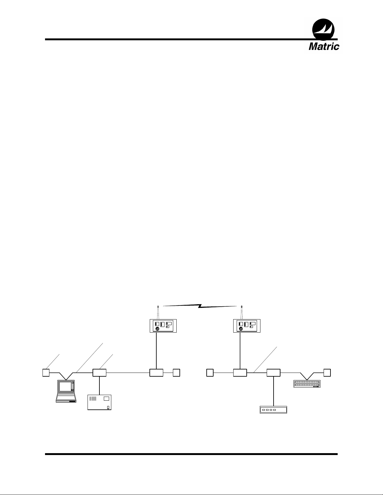
The Wireless CAN Bridge functions as a wireless link that transfers CAN messages.
Using the Wireless CAN Bridge, nodes on either side of a wireless link can
communicate at a typical separation of 500 feet. A full 64 node DeviceNet* can be
implemented depending on scan rates and frame density. Since actual CAN messages
are transferred, the Wireless CAN Bridge supports any type of CAN bus standard
including CAN Open and CAN Kingdom.
Terminator Tap
SCANNER
NODE
CAN
BRIDGE
Trunk Line
MOTOR
CONTROL
NODE
Virtual
Trunk
Line
CAN
BRIDGE
Trunk Line
(extended by CAN Bridge)
I/O BLOCK
NODE
SENSOR
NODE
Matric Technical Manual 185-XXXX, V1 Page 1 of 11
Page 2

Technical Manual
Wireless CAN Bridge 500 (CB-500)
SPECIFICATIONS:
Functional
1200 frames per second transfer rate (max)
Supports any CAN Bus or DeviceNet* (Bosch CAN 2.0b)
Five pin male micro connector
16 bit CPU
CPU watchdog
Radio
Typical range of 50 feet
2.4 – 2.4835 GHz with 16 channels
FSK modulation
Output power, .003 mW
Single heterodyne conversion
Radio complies with FCC Part 15B, no user license required
Configuration Options
Configuration via internal dip switches
Radio link master or slave
Standard versus extended CAN frame formats
Host Interface baud rate (125K, 250K, 500K)
Channel (1-16)
Radio retry level
Power Source
7-30VDC, 200 mA at 24VDC +/- 5%
Status Indicators
Signal strength
Bus loading
Data Loss Cause
Power
Physical
Size: 3 1/8 X 3 X 6 5/16 Inches
Weight: 1 Lb
DIN rail or panel mount
Sealed enclosure
Operational temperature 0°C to 70°C
Storage temperature -40ºC to 85ºC
Matric Technical Manual 185-XXXX, V1 Page 2 of 11
Page 3

Technical Manual
Wireless CAN Bridge 500 (CB-500)
APPLICATION:
The Wireless CAN Bridge provides a frame transfer rate of 1200 CAN frames per
second (fps) which is roughly equivalent to a fully loaded 125k baud system. The
effectiveness of the CAN Bridge in any particular application depends on network
loading (including bursts). The loading on a CAN based network is effected by a
number of factors including: polling rate of the network scanner, node count, and
change-of-state activity. According to ODVA, 30% loading is recommended for
DeviceNet systems employing change-of-state devices and 80% loading is
recommended for polled DeviceNet systems. Heavily loaded systems increase the
probability that CAN messages will be discarded due to RF bandwidth limitations.
The transfer rate of 1200 fps is based on a typical scenario of 500 feet separation
without significant RF obstacles. The actual transfer rate in any application is
dependent upon the quality of the RF link. Structural components such as steel walls or
decking, earth tunnels, and metal equipment can effect the quality of the RF link. Also,
radiation sources such as other radio systems, high power switching, and magnetic
fields can effect the quality of the RF link. A site assessment should be performed at
any site where a new RF control is to be installed.
The Wireless CAN Bridge provides a point-to-point data transfer in order to achieve the
required throughput over the wireless link. A system requiring multiple wireless links
can accomplish this using multiple pairs of the Wireless CAN Bridge. Up to three CAN
Bridge pairs can be operated in close proximity in most situations. To operate in close
proximity, use channels with the widest possible separation (channels 0, 7, and 14).
System integrators must be aware of potential Near / Far problems and the complexity
related to operating DSSS radios in such installations. Also, the number of radio pairs
that can be operated in proximity is dependent upon the actual distances between
radios. Refer to the installation section for details regarding radio issues, site
assessment, and optimal antenna placement.
The rate at which CAN frames are received and transmitted by the Wireless CAN
Bridge falls within the timing constraints of Bosch CAN Standard 2.0b. While meeting
network requirements for data link and higher levels of communication, the time
required for retransmission may still have an effect on the overall timing of a control
system.
Matric Technical Manual 185-XXXX, V1 Page 3 of 11
Page 4
Technical Manual
Wireless CAN Bridge 500 (CB-500)
CONFIGURATION:
Configuration of the Wireless CAN Bridge is accomplished by manually setting switches
inside its enclosure. The CAN Bridge enclosure lid must be removed to access the
configuration switches. Users may only perform the configuration described in this
manual. Changing other switch or trimmer settings may invalidate agency approvals.
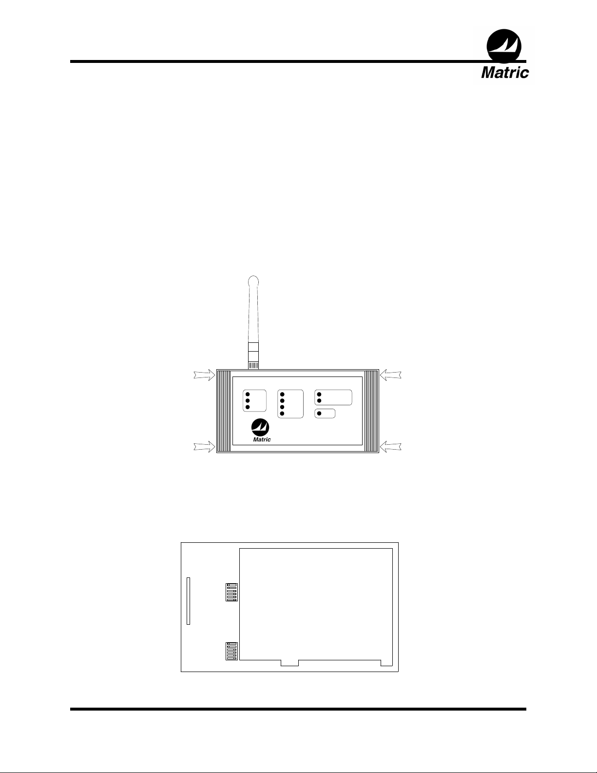
To access configuration switches, first, use a flat screwdriver to pry off the two
decorative covers at the right and left ends of the lid. Four pry slots are provided as
shown below. Then unscrew the four screws that attach the lid to the chassis of the
Wireless CAN Bridge using a philips or a flat screwdriver.
SIGNAL
STRONG
POOR
WEAK
The Wireless CAN Bridge has 12 configuration switches arranged in 3 banks S1, S2,
and S3. Each bank, contains 4 switches. These switches allow the user to easily
customize the Wireless CAN Bridge to fit the desired application.
OFF ON
1
2
3
S1
4
5
6
LED CONNECTOR
OFF ON
1
2
3
S2
4
5
6
LOADING DATA LOSS CAUSE
HEAVY
MODERATE
NORMAL
LIGHT
BUFFER OVERRUN
RETRY EXHAUSTED
POWER
WIRELESS CAN BRIDGE
RADIO BOARD
Matric Technical Manual 185-XXXX, V1 Page 4 of 11
Page 5
Technical Manual
Wireless CAN Bridge 500 (CB-500)
IMPORTANT: Employ ESD precautions to avoid static discharge when touching the
CAN Bridge circuit board. ESD can cause damage leading to catastrophic or
intermittent product failure modes.
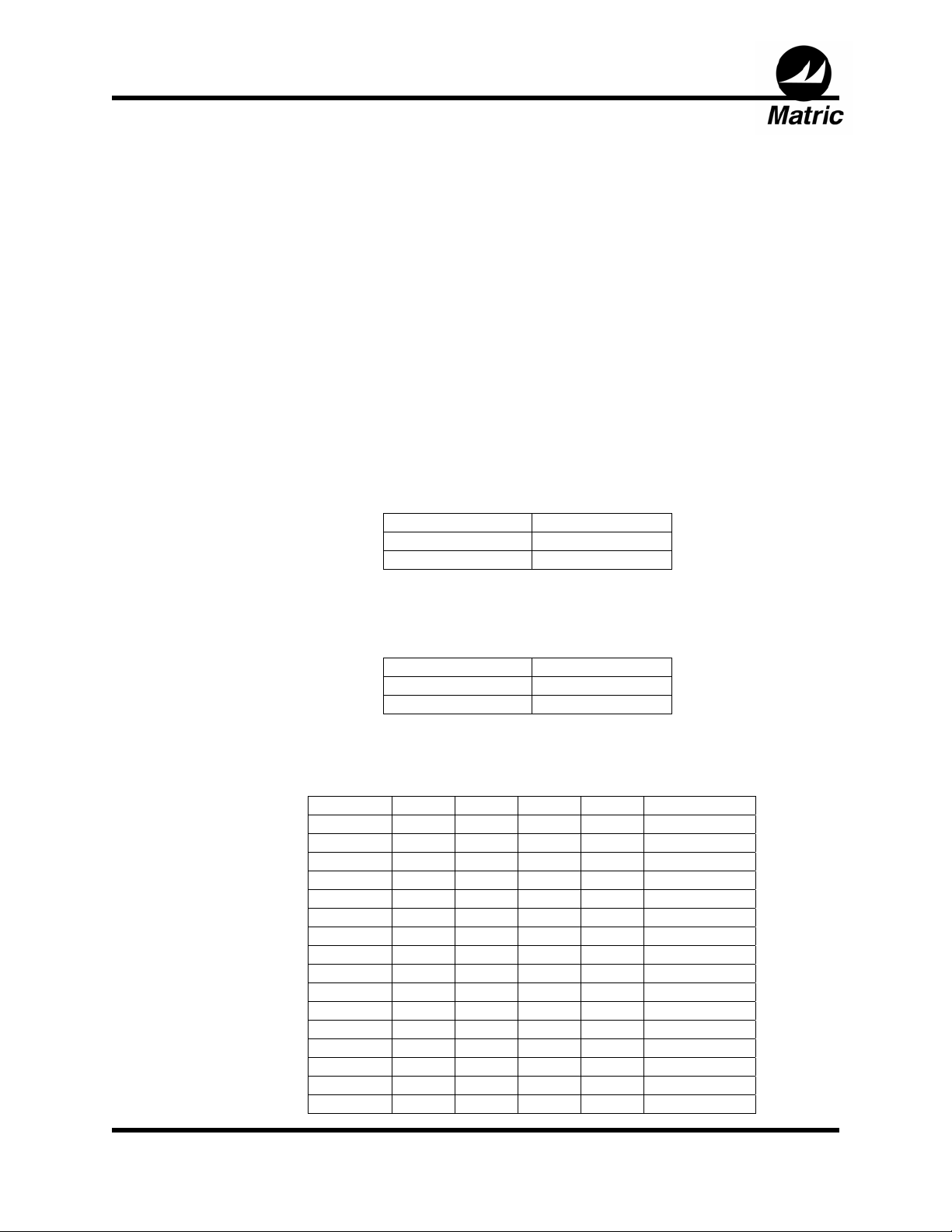
The following paragraphs describe each switch setting in more detail. The format Sb:s,
where b is the bank number and s is the switch number within that bank, will be used.
The “as shipped” settings are shown with an asterisk “*”.
The CB-500 must be reset (power cycled) before switch settings take effect.
Switch S1:1 Selects Node Communication Type for internal radios. A
Radio System must consist of only one Server (master) and
only one Client (slave) per channel. The Server is the
initiator of the radio pair. Before the radios link, the Client
will only listen for a Server and the Server will transmit to find
a Client.
Radio Operation S1:1
Server ON
Client OFF
Switch S1:2 Enables or disables the DeviceNet functions for the CAN
Bridge.
DeviceNet S1:2
Enabled ON
Disabled OFF
Switches S1:3,4,5,6 Selects the operating channel. A master/slave pair must be
set to the same channel to operate properly.
Channel S1:3 S1:4 S1:5 S1:6 Freq (GHz)
1*
2 ON ON ON OFF 2.410
3 ON ON OFF ON 2.415
4 ON ON OFF OFF 2.420
5 ON OFF ON ON 2.425
6 ON OFF ON OFF 2.430
7 ON OFF OFF ON 2.435
8 ON OFF OFF OFF 2.440
9 OFF ON ON ON 2.445
10 OFF ON ON OFF 2.450
11 OFF ON OFF ON 2.455
12 OFF ON OFF OFF 2.460
13 OFF OFF ON ON 2.465
14 OFF OFF ON OFF 2.470
15 OFF OFF OFF ON 2.475
16 OFF OFF OFF OFF 2.480
Matric Technical Manual 185-XXXX, V1 Page 5 of 11
ON
*
ON
*
ON
*
ON
*
2.405*
Page 6
Technical Manual
Wireless CAN Bridge 500 (CB-500)
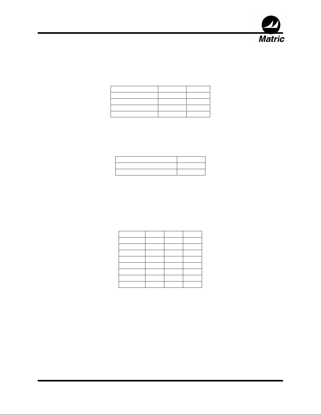
Switches S2:1,2 Selects the bit rate of the CAN or DeviceNet network.
Switches S2:3 Selects Standard or Extended CAN framing. DeviceNet*
Switches S2:4,5,6 Selects the number of retries. The radio will retransmit an
Bit Rate (Bits/Sec.) S2:1 S2:2
*
125K
250K ON OFF
500K OFF ON
125K OFF OFF
ON
*
ON
*
uses standard framing. Some varieties of CAN may use
extended framing.
CAN Type
11 bit (Standard CAN)
29 bit (Extended CAN) OFF
S2:3
*
ON
*
unsuccessful packet the selected number of times before
discarding the packet. Increasing retries may slow the
communication process, but may help reduce discarded
packets.
Retries S2:4 S2:5 S2:6
1 ON ON ON
2 ON ON OFF
4 ON OFF ON
8 ON OFF OFF
16 OFF ON ON
32 OFF ON OFF
64 OFF OFF ON
128 OFF OFF OFF
Matric Technical Manual 185-XXXX, V1 Page 6 of 11
Page 7

Technical Manual
Wireless CAN Bridge 500 (CB-500)
INDICATORS:
The Wireless CAN Bridge provides three separate groups of diagnostic LED indicators.
The groups are labeled “Signal”, “Loading”, and “Data Loss Cause.” In addition to
these groups, a power indication LED is also provided.
Signal Indicators The signal indicators provide information about the integrity and
robustness of the RF Signal. The three levels may be described as
a function of data throughput.
Data Loss Cause The data loss cause indicators provide information about packets
Strong Indicates the best data throughput. Data packets are
being transferred to the radio at a rate equivalent to
between 100% and 110% of full CAN trunk line loading
(at 125k baud).
Poor Reduced data throughput. Data packets are being
transferred at a rate between 50% and 100% loading at
125k baud.
Weak Radios are linked, but data throughput is low. Data
packets are being transferred at a rate between 0% to
50% loading.
No Indicators Data rate is zero. No RF link established.
that are discarded due to throughput constraints. Two indications
are provided, Buffer Overrun and Retry Exhausted. Scanner retries
must be set at a level that mitigates data loss at the system level.
Buffer Overrun CAN packets entering the transmit buffer have
overrun the RF link capacity. One or more CAN
messages are discarded.
Retry
Exhausted
No Indicators No data loss.
The configured number of RF transmit retries
has been exceeded. One or more RF packets
are discarded. Note: RF data packets may
contain up to 2 CAN messages.
Matric Technical Manual 185-XXXX, V1 Page 7 of 11
Page 8
Technical Manual
Wireless CAN Bridge 500 (CB-500)
Loading Indicators The loading indicators show the number of CAN packets that are
being written to the RF transmit buffer. The four levels may be
described as a function of RF bandwidth usage by CAN packets.
Note: Buffer overruns may effect this indicator due to discarded
CAN packets.
Power Indicator The power indicator implies the presence of electrical power. It is a
Heavy 50 % - 100 % of the available bandwidth is
being utilized for CAN messages.
Moderate 35 % - <50 % of the available bandwidth is
being utilized for CAN messages.
Normal 10 % - <35 % of the available bandwidth is
being utilized for CAN messages.
Light 0+ % - <10 % of the available bandwidth is being
utilized for CAN messages.
No Indicators No CAN messages transferred.
hardwired LED that does not indicate the quality of the power
detected.
Power LED On DC Power is On.
No Illumination DC Power is Off.
Matric Technical Manual 185-XXXX, V1 Page 8 of 11
Page 9

Technical Manual
Wireless CAN Bridge 500 (CB-500)
INSTALLATION:
The Wireless CAN Bridge can be bolted directly to a control panel, or mounted to a DIN
rail. Remove the two decorative covers at the right and left ends of the lid to access the
mounting holes for direct panel mount (or to attach the DIN rail clips). See the
Configuration section for instruction on removing the decorative covers.
CAUTION: Many types of threadlock will weaken the plastic enclosure of the CAN
Bridge. Instead, use lock washers, or a threadlock that will not damage plastic (such as
Premabond MM115) to secure mounting screws. Also, do not over-torque panel
mounting screws. Use washers as needed to protect the enclosure and provide a solid
base for tightening mounting screws.
A DIN rail mounting kit is available for attaching the Wireless CAN Bridge to either EN
50-022 or EN 50-035 din rails. The DIN rail mounts are attached to the same holes
used for direct panel mounting.
The Wireless CAN Bridge provides a sealed micro style connector that complies with
the physical standards for DeviceNet* connectors. The CB-300 requires a tap to
interface into the DeviceNet* trunk line. The pinout for the connector is shown at left.
43
5
12
Male (pins)
1 - Drain (bare)
2 - V+ (red)
3 - V- (black)
4 - CAN_H (white)
5 - CAN_L (blue)
Matric Technical Manual 185-XXXX, V1 Page 9 of 11
Page 10

Technical Manual
Wireless CAN Bridge 500 (CB-500)
APPROVALS:
The Wireless CAN Bridge has been tested and found to comply with the limits for a
Class A digital device, pursuant to Part 15 of the FCC Rules. These limits are designed
to provide reasonable protection against harmful interference when the equipment is
operated in a commercial environment. The Wireless CAN Bridge generates, uses, and
can radiate radio frequency energy and, if not installed and used in accordance with the
instruction manual, may cause interference to radio communications and harmful
microwave emissions. To limit exposure radio frequency radiation, the CAN Bridge
should be installed and operated with a minimum distance of 20 centimeters between
the antenna and all persons and must not be collocated or operating in conjunction with
any other antenna or transmitter.
Operation of this equipment in a residential environment is likely to cause harmful
interference to other residential devices in which case the user will be required to
correct the interference at their own expense. Changes or modifications not expressly
approved by Matric could void the user’s authority to operate the Wireless CAN Bridge.
The Wireless CAN Bridge has been tested and found to comply with European
Community EMC Emissions and Immunity requirements (EN 300 328 and EN 301 489
01).
Operation is subject to the following two conditions:
(1) this device may not cause interference, and
(2) this device must accept any interference, including interference that may cause
undesired operation of the device.
The Wireless CAN Bridge has been designed to operate with the antenna listed below,
and having a maximum gain of 1 dB. Antennas not included in this list or having a gain
greater than 1 dB are strictly prohibited for use with this device. The required antenna
impedance is 50 ohms.
Approved Antennas
Manufacturer Part Number Description
Centurion WCR2400SMRP ½ wave coaxial dipole
Matric Technical Manual 185-0053, V6
Page 10 of 11
Page 11

Technical Manual
Wireless CAN Bridge 500 (CB-500)
For technical support, contact:
Matric
2099 Hill City Road
Seneca, PA 16346
(814) 677-0716
www.matric.com
Matric Technical Manual 185-XXXX, V1 Page 11 of 11
 Loading...