

Page 1

xPC Target™ 4
API Guide
Page 2

How to Contact The MathWorks
www.mathworks.
comp.soft-sys.matlab Newsgroup
www.mathworks.com/contact_TS.html Technical Support
suggest@mathworks.com Product enhancement suggestions
bugs@mathwo
doc@mathworks.com Documentation error reports
service@mathworks.com Order status, license renewals, passcodes
info@mathwo
com
rks.com
rks.com
Web
Bug reports
Sales, prici
ng, and general information
508-647-7000 (Phone)
508-647-7001 (Fax)
The MathWorks, Inc.
3 Apple Hill Drive
Natick, MA 01760-2098
For contact information about worldwide offices, see the MathWorks Web site.
xPC Target™ API Guide
© COPYRIGHT 2002–20 10 by The MathWorks, Inc.
The software described in this document is furnished under a license agreement. The software may be used
or copied only under the terms of the license agreement. No part of this manual may be photocopied or
reproduced in any form without prior written consent from The MathW orks, Inc.
FEDERAL ACQUISITION: This provision applies to all acquisitions of the Program and Documentation
by, for, or through the federal government of the United States. By accepting delivery of the Program
or Documentation, the government hereby agrees that this software or documentation qualifies as
commercial computer software or commercial computer software documentation as such terms are used
or defined in FAR 12.212, DFARS Part 227.72, and DFARS 252.227-7014. Accordingly, the terms and
conditions of this Agreement and only those rights specified in this Agreement, shall pertain to and govern
theuse,modification,reproduction,release,performance,display,anddisclosureoftheProgramand
Documentation by the federal government (or other entity acquiring for or through the federal government)
and shall supersede any conflicting contractual terms or conditions. If this License fails to meet the
government’s needs or is inconsistent in any respect with federal procurement law, the government agrees
to return the Program and Docu mentation, unused, to The MathWorks, Inc.
Trademarks
MATLAB and Simulink are registered trademarks of The MathWorks, Inc. See
www.mathworks.com/trademarks for a list of additional trademarks. Other product or brand
names may be trademarks or registered trademarks of their respective holders.
Patents
The MathWorks products are protected by one or more U.S. patents. Please see
www.mathworks.com/patents for more information.
Page 3

Revision History
July 2002 Online only New for Version 2 (Release 13)
October 2002 Online only Updated for Version 2 (Release 13)
September 2003 Online only Revised for Version 2.0.1 (Release 13SP1)
June 2004 Online only Revised for Version 2.5 (Release 14)
August 2004 Online only Revised for Version 2.6 (Release 14+)
October 2004 Online only Revised for Version 2.6.1 (Release 14SP1)
November 2004 Online only Revised for Version 2.7 (Release 14SP1+)
March 2005 Online only Revised for Version 2.7.2 (Release 14SP2)
September 2005 Online only Revised for Version 2.8 (Release 14SP3)
March 2006 Online only Revised for Version 2.9 (Release 2006a)
May 2006 Online only Revised for Version 3.0 (Release 2006a+)
September 2006 Online only Revised for Version 3.1 (Release 2006b)
March 2007 Online only Revised for Version 3.2 (Release 2007a)
September 2007 Online only Revised for Version 3.3 (Release 2007b)
March 2008 Online only Revised for Version 3.4 (Release 2008a)
October 2008 Online only Revised for Version 4.0 (Release 2008b)
March 2009 Online only Revised for Version 4.1 (Release 2009a)
September 2009 Online only Revised for Version 4.2 (Release 2009b)
March 2010 Online only Revised for Version 4.3 (Release 2010a)
Page 4

Page 5

1
xPC T arget API, xPC Target COM API, and xPC Target
API for Microsoft .NET Framework
............... 1-2
Contents
Introduction
What Is xPC Target API?
What Is xPC Target COM API?
What is the xPC Target API for Microsoft .NET
Framework?
Required Products
.................................... 1-8
................................. 1-9
........................... 1-4
...................... 1-6
xPC Target API
2
Before You Start ................................... 2-2
Introduction
Important Guidelines
Visual C Example
Introduction
Directories and Files
Building the xPC Target Application
Creating a Visual C Application
Building a Visual C Application
Running a Visual C xPC Target API Application
UsingthexPCTargetAPICApplication
C Code for sf_car_xpc.c
...................................... 2-2
.............................. 2-2
.................................. 2-5
...................................... 2-5
............................... 2-5
.................. 2-7
...................... 2-7
...................... 2-12
........ 2-12
.............. 2-13
............................. 2-19
v
Page 6

xPC Target COM API
3
Before You Start ................................... 3-2
Example Visual Basic GUI Using COM Objects
Introduction
Description of Simulink Water Tank M odel
Creating a Simulink Target Model
Tagging Block Parameters
Tagging Block Signals
Creating the Target Application and Model-Specific COM
Library
Model-Specific COM Interface Library
(model_nameCOMiface.dll)
Creating a New Microsoft
Referencing the x PC Target COM API and M odel-Specific
COM Libraries
Creating the Graphical Interface
Setting Properties
Writing Code
Creating the General Declarations
Creating the Load Procedure
Creating Event Procedures
Referencing Parameters and Signals Without Using
Tags
Testing the Visual Basic Application
Building the Visual Basic Application
Deploying the API Application
Creating a New Visual Basic Project Using Microsoft
Visual Studio 8.0 ................................ 3-47
...................................... 3-5
................... 3-7
.......................... 3-8
.............................. 3-11
........................................ 3-14
....................... 3-18
®
Visual Basic Project ......... 3-20
................................. 3-22
..................... 3-27
................................. 3-29
..................................... 3-31
................... 3-33
........................ 3-33
.......................... 3-35
.......................................... 3-41
.................. 3-45
................. 3-45
....................... 3-46
....... 3-4
............ 3-5
®
vi Contents
xPC Target COM API Demos and Scripts
4
Microsoft®Visual Basic .NET Demo ................. 4-2
Introduction
Before Starting
Accessing the Demo Project Solution
...................................... 4-2
................................... 4-3
.................. 4-3
Page 7

RebuildingtheDemoProjectSolution ................. 4-4
Using the Demo Executable
......................... 4-4
Microsoft
Introduction
Before Starting
Accessing the sf_car_xpc Project
Rebuilding the sf_car_xpc Project
Using the sf_car_xpc Executable
Tcl/Tk Scripts
Introduction
Required Tcl/Tk Software
Using the Demo Scripts
®
Visual Basic 6.0 Demo .................... 4-5
...................................... 4-5
................................... 4-6
..................... 4-6
.................... 4-7
..................... 4-7
..................................... 4-8
...................................... 4-8
........................... 4-9
............................ 4-9
xPC Target API for Microsoft .NET Framework
5
xPC Target API Reference .......................... 5-2
Introduction
Usage Notes
xPC Target .NET for the .NET Framework Demo
...................................... 5-2
...................................... 5-4
....... 5-5
xPC Target API for Microsoft .NET Framework
Classes
MathWorks.xPCTarget.FrameWork.xPCApplication
class
MathWorks.xPCTarget.FrameWork.xPCAppLogger
class
MathWorks.xPCTarget.FrameWork.-
xPCDataFileScSignalObject class
MathWorks.xPCTarget.FrameWork.-
xPCDataHostScSignalObject class
MathWorks.xPCTarget.FrameWork.-
xPCDataLoggingObject class
MathWorks.xPCTarget.FrameWork.xPCDirectoryInfo
class
MathWorks.xPCTarget.FrameWork.xPCDriveInfo
class
......................................... 5-6
.......................................... 5-7
.......................................... 5-8
.................. 5-8
................. 5-9
...................... 5-9
.......................................... 5-9
.......................................... 5-10
vii
Page 8

MathWorks.xPCTarget.FrameWork.xPCException
class
.......................................... 5-10
MathWorks.xPCTarget.FrameWork.xPCFileInfo class
MathWorks.xPCTarget.FrameWork.xPCFileScope
class
.......................................... 5-11
MathWorks.xPCTarget.FrameWork.-
xPCFileScopeCollection class
MathWorks.xPCTarget.FrameWork.xPCFileScopeSignal
class
.......................................... 5-12
MathWorks.xPCTarget.FrameWork.-
xPCFileScopeSignalCollection class
MathWorks.xPCTarget.FrameWork.xPCFileStream
class
.......................................... 5-12
MathWorks.xPCTarget.FrameWork.xPCFileSystem
class
.......................................... 5-13
MathWorks.xPCTarget.FrameWork.xPCFileSystemInfo
class
.......................................... 5-13
MathWorks.xPCTarget.FrameWork.xPCHostScope
class
.......................................... 5-13
MathWorks.xPCTarget.FrameWork.-
xPCHostScopeCollection class
MathWorks.xPCTarget.FrameWork.xPCHostScopeSignal
class
.......................................... 5-14
MathWorks.xPCTarget.FrameWork.-
xPCHostScopeSignalCollection class
MathWorks.xPCTarget.FrameWork.xPCLog class
MathWorks.xPCTarget.FrameWork.xPCOutputLogger
class
.......................................... 5-15
MathWorks.xPCTarget.FrameWork.xPCParameter
class
.......................................... 5-15
MathWorks.xPCTarget.FrameWork.xPCParameters
class
.......................................... 5-15
MathWorks.xPCTarget.FrameWork.xPCScope class
MathWorks.xPCTarget.FrameWork.xPCScopes class
MathWorks.xPCTarget.FrameWork.xPCSignal class
MathWorks.xPCTarget.FrameWork.xPCSignals class
MathWorks.xPCTarget.FrameWork.xPCStateLogger
class
.......................................... 5-17
MathWorks.xPCTarget.FrameWork.xPCTargetPC
class
.......................................... 5-17
MathWorks.xPCTarget.FrameWork.xPCTargetScope
class
.......................................... 5-19
MathWorks.xPCTarget.FrameWork.-
xPCTargetScopeCollection class
...................... 5-11
................ 5-12
..................... 5-14
................ 5-14
....... 5-14
..... 5-16
.... 5-16
.... 5-16
.... 5-17
................... 5-19
... 5-11
viii Contents
Page 9

MathWorks.xPCTarget.FrameWork.-
xPCTargetScopeSignalCollection class
MathWorks.xPCTarget.FrameWork.xPCTETLogger
class
.......................................... 5-20
MathWorks.xPCTarget.FrameWork.xPCTimeLogger
class
.......................................... 5-20
EventArg Classes
xPC Target API for Microsoft .NET Framework —
Alphabetical List
................................. 5-20
................................ 5-22
.............. 5-20
APIFunctionandMethodReference
6
CAPIFunctions ................................... 6-2
Logging, Scope, and File System Structures
Communications Functions
Target Application Functions
Data Logging Functions
Scope Functions
File System Functions
Target Scope Functions
Monitoring and Tuning Functions
Miscellaneous Functions
................................... 6-5
......................... 6-3
........................ 6-3
............................ 6-5
............................. 6-7
............................ 6-8
.................... 6-9
............................ 6-9
............ 6-2
COM API Methods
Communication Objects (xPCProtocol)
Scope Objects (xPCScopes)
Target Objects (xPCTarget)
File System Objects (xPCF ileSystem)
................................. 6-11
.......................... 6-12
......................... 6-14
................ 6-11
................. 6-16
ix
Page 10

7
A
API F unctions and Methods
xPC Target C API Error Messages
Index
x Contents
Page 11

Introduction
Using either the xPC Target™ API dynamic link library (DLL) or the xPC
Target component object model (COM) API library, you can create custom
applications to control a real-time application running on the target PC. You
generate real-time applications from Simulink
• “xPC Target API, xPC Target COM API, and xPC Target API for Microsoft
.NET Framework” on page 1-2
• “What Is xPC Target API?” on page 1-4
• “What Is xPC Target COM API?” on page 1-6
®
models.
1
• “WhatisthexPCTargetAPIforMicrosoft.NETFramework?”onpage1-8
• “Required Products” on page 1-9
Page 12

1 Introduction
xPC Target API, xPC Target COM API, and xPC Target API
for Microsoft .N
ET Framework
The xPC Target A
functionality
performance o
library. The x
thesamebasic
human-machi
Target softw
threadsafe.
The xPC Targ
any high-le
asuiteofi
interface
programmi
applicat
Target ap
API, you w
Java) tha
you are a
graphic
Target a
COM API
Micros
The xPC
that m
devel
vel language application. The xPC Target COM API consists of
nterfaces that you can reference while building a graphic user
(GUI) application. You can incorporate these interfaces using
ng environments that work with COM objects. A user can use an
ion written through either interface to load, run, and monitor an xPC
plication without interacting with MATLAB
rite the application in a high-level language (such as C, C++, or
t w orks with an xPC Target application; this option requires that
n experienced programmer. With xPC Target COM API, yo u use a
al development environment to create a GUI that works with an xPC
pplication. Designed to work with Microsoft COM, the xPC Target
conforms to the component object model standard established by
oft.
Target API is distributed with two dynamic link libraries (DLLs)
ake it easier to integrate with various development tools, tailoring the
opment environment to your needs:
PI and xPC Target COM API interfaces provide the same
for you to write custom applications. There is no difference in
r functionality between applications written against either
PC Target API for Microsoft
functionality for you to develop solutions (applications,
ne interface (HMI) software, batch runs) that use the xPC
are. Note that the C API is threadsafe. The COM API is not
et API DLL consists of C functions that you can incorporate into
®
.NET Framework provides
®
. With the xPC Target
1-2
• Afun
• Acom
The
• “Wh
• “Wh
ction library (
ponent library (
following sections describe each library:
at Is xPC Target API?” on page 1-4
at Is xPC Target COM API?” on page 1-6
xpcapi.dll)
xpcapicom.dll)
Page 13

xPCTarget™API,xPCTarget™COMAPI,andxPCTarget™APIforMicrosoft®.NET Framework
The xPC Target API for Microsoft .NET Framework provides a .NE T object
model provides objects that you can interact with. See Chapter 5, “xPC Target
API for Microsoft .NET Framework” for a description of the API.
Note In this book, second-person references apply to those who write the
xPC Target API and COM API applications. For example, “You can assign
multiple labels to one tag.” Third-person references apply to those who run
the xPC Target API and COM API applications. For example, “You can later
distribute this executable to users, who can then use the GUI application to
work with target applications.”
1-3
Page 14

1 Introduction
What Is xPC Target API?
The xPC Target API consists of a series of C functions that you can call from a
C or C++ application. Thesefunctionsenableyouto
• Establish communication between the host PC and the target PC via an
Ethernet or serial connection
• Load the target application, a
• RunthatapplicationonthetargetPC
• Monitor the behavior of the target application on the target PC
• Stop that application on the target PC
• Unload the target application from the target PC
• Close the connection to the target PC
xpcapi.dll file contains the xPC Target API dynamic link library. It
The
contains over 90 functions that enable run-time linking rather than static
linking at compile time. The functions provide all the information and
accessibility needed to access the target application. Accessing the xPC Target
API DLL is beneficial when you are building applications using development
environments s uch as Microsoft Foundation Class Library/Active Template
Library (MFC/ATL), DLL, Win32 (non-MFS) program and DLL, and console
programs integrating with third-party product APIs (for example, Altia).
All custom xPC Target API applications must link with the
file (xPC API DLL). Also associated with the dynamic link library is the
xpcinitfree.c file. This file contains functions that load and unload the
xPC Target API. You must build this file along with the custom xPC Target
API application.
.dlm file, to the ta rget PC
xpcapi.dll
1-4
The documentation reflects the fact that the API is written in the C
programming language. However, the API functions are usable from other
languages and applications, such as C++ and Java.
Page 15

What Is xPC Target™ API?
Note To write a non-C application that calls functions in the xPC Target API
library, refer to the compiler documentation for a description of how to access
functions from a library DLL. You must follow these directions to access the
xPC Target API DLL.
The following chapters describe the xPC Target API in more detail:
• Chapter 2, “xPC Target API” descri bes how to create a C xPC Target API
application.
• Chapter 6, “API Function and Method Reference” and Chapter 7, “API
Functions and Methods” describe the xPC Target C and COM API functions.
1-5
Page 16

1 Introduction
What Is xPC Target COM API?
The xPC Target COM API is an open environment application program
interface designed to work with Microsoft COM and the xPC Target API. The
xPC Target COM API provides the same functionality as the xPC Target A PI.
It is a programming layer that sits between you and the xPC Target API.
The difference is that while the xPC Target API is a dynamic link library of
C functions, the xPC Target COM API dynamic link library is an organized
collection of objects, classes, and functions. You access this collection through
a graphical development environment such as Microsoft Visual Basic. Using
such a graphical development environment, you can create a custom GUI
application that can work with one xPC Target application. While the xPC
Target API requires you to be an accomplished C or C++ programmer, the
xPC Target COM API makes no such demand.
The xPC Target COM API library depends on
dynamic link library. However, the xPC Target API is independent of the
xPC Target COM API.
The xPC Target COM API has the following features:
• A DLL component server library —
DLL library COM interface consisting of component interfaces that access
the target PC. The COM API library enhances the built-in functionality of
a programming language by allowing you to easily access the xPC Target
API for rapid development of xPC Target GUI.
• Built on top of the xPC Target API — Via an application such as Visual
Basic,
full access to all the data and methods needed to interface with an xPC
Target application. It also enables search functionality and bidirectional
browsing capabilities. Generally, you view object models by selecting a type
and v iewing its members. Usin g the xPC Target COM API library, you can
select a member and view the types to which it belongs.
• Programming language independent — This section describes how to create
an xPC Target COM API application using Visual Basic. However, the xPC
Target COM API interface is not limited to this third-party product. You
can add the COM API library to any development environment that can
access COM libraries, such as Visual C ++ or Java, as well as scripting
languages such as Perl, Python, and Basic.
xpcapicom.dll, using a structured object m odel hierarchy, provides
xpcapicom.dll is a component server
xpcapi.dll,thexPCTarget
1-6
Page 17

What Is xPC Target™ COM API?
• Ideal for use with Visual Basic — The xPC Target COM API works well
with Visual Basic, and extends the event-driven programming environment
of Visual Basic.
See Chapter 3, “xPC Target COM AP I” for a description of how to use the
xPC Target COM API library.
1-7
Page 18

1 Introduction
What is the xPC Target API for Microsoft .NET Framework?
The xPC Target API for Microsoft .NET Framework consists of objects
arranged in hierarchical order. Each of these objects has methods and
properties that allow you to manipulate and interact with it. The API provides
a number of classes, including those for target applications, scopes, the file
system, and the target PC. The xPCTargetPC class is the main class that
sits on top of a hierarchy of classes.
See Chapter 5, “xPC Target A P I for Microsoft .NET Framework” for a
description of the xPCTargetPC class hierarchy and the API that supports it.
1-8
Page 19

Required Products
Refer to “Required Products” in the xPC Target Getting Started Guide for a
list of the required xPC Target products. In addition, you need the following
products:
• Third-Party Compiler — Use a third-party compiler to build a custom
application that calls functions from the xPC API library. Although the
xPC API library is written in C, you can write the application that calls
these functions in another high-level language, such as C++. You can use
any compiler that can generate code for Win32 systems.
To write a non-C application that calls functions in the xPC Target API
library, refer to the compiler documentationforadescriptionofhowto
access functions from a library DLL. You must follow these directions to
access the xPC Target API DLL.
• Third-Party Graphical Development Environment — Use a third-party
graphical development environment to build a custom application that
references interfaces in the xPC COM API library. Layered on top of the
xPC API library, the xPC COM API library enables you to write custom
applications using a component object model library. You can use any
compiler that can work with component object model (COM) objects.
Required Products
1-9
Page 20

1 Introduction
1-10
Page 21

xPC Target API
• “Before You Start” on page 2-2
• “Visual C Example” on page 2-5
2
Page 22

2 xPC Target A PI
Before You Start
In this section...
“Introduction” on page 2-2
“Important Guidelines” on page 2-2
Introduction
This chapter describes how to write a custom application using the xPC
Target API. This API enables you to write high-level language applications to
load an xPC Target application, and run and control it.
Before you start, read this section for important notes on writing custom
applications based on the xPC Target API. It is assumed that you already
know how to write C or C++ code.
This chapter provides tutorials on how to generate a C application for xPC
Target. It also provides some guidelines on using the xPC Target API. Refer
to “Visual C Example” on page 2-5 for tutorials that you can follow to create,
build, and run a sample Visual C program.
2-2
For the xPC Target API function synopses and descriptions, refer to “API
Function and Method Reference”.
Important Guidelines
This section describes some guide lines you should keep in mind before
beginning to write xPC Target API applications with the xPC Target API DLL:
• You must carefully match the data types of the functions documented in
the API function reference. For C, the API includes a header file that
matches the data types.
• To write a non-C application that calls functions in the xPC Target API
library, refer to the compiler documentationforadescriptionofhowto
access functions from a library DLL. You must follow these directions to
access the xPC Target API DLL
Page 23

Before You Start
• Ifyouwanttorebuildthemodelsf_car_ xpc.mdl,orotherwiseuse
MATLAB, you must have xPC Target Version 2.0 or later. This is the
version of xPC Target that comes with Release 13 (MATLAB 6.5) or later.
To determine the version of xPC Target you are currently using, at the
MATLAB command line, type
xpclib
This opens the xPC Target Simulink blocks library. The version of xPC
Target should be at the bottom of the window.
• You can work with xPC Target applications with either MAT LAB or an
xPC Target API application. If you are working with an xPC Ta rget
application simultaneously with a MATLAB session interacting with the
target, keep in mind that only one application can access the target PC at
a time. To move from the MATLAB session to your application , in the
MATLAB Command W indow, type
close(xpc)
ThisfreestheconnectiontothetargetPCforusebyyourxPCTargetAPI
application. Conversely, you will need to quit your application, or do the
equivalent of calling the function
xPCClosePort, to access the target from
a MATLAB session.
• All xPC Target API functions that communicate with the target PC check
for time-outs during communication. If a time-out occurs, these functions
will exit with th e global variable
xPCError set to either ECOMTIMEOUT
(serial connections) or ETCPTIMEOUT (TCP/IP connections). Use the
xPCGetLoadTimeOut and xPCSetLoadTimeOut functions to get and set the
time-out values, respectively.
There are a few things that are not covered in Chapter 6, “API Function and
Method Reference” and Chapter 7, “API Functions and Methods” for the
individual functions, because they are common to almost all the functions in
the xPC Target API. These are
• Almost every function (except
xPCGetLastError,andxPCErrorMsg) has as one of its parameters the
integer variable
port. This variable is returned by xPCOpenSerialPort
xPCOpenSerialPort, xPCOpenTcpIpPort,
and xPCOpenTcpIpPort , and is the placeholder for the communications link
2-3
Page 24

2 xPC Target A PI
withthetargetPC.Thereturnedvaluefromthesetwofunctionsshould
be used in the other functions to ensure that the proper communications
channel is used.
• Almost every function (except
global error value in case of error. The application obtains this value by
calling the function
about the error by using the function
values of the error numbers are subject to change, a zero value always
means that the operation completed without errors, while a nonzero value
typically signifies an error condition. Note also that the library resets the
error value every time an API function is called; therefore, your application
should check the error status as soon as possible after a function call.
Some functions also use their return values (if applicable) to signify that
an error has occurred. In these cases as well, y ou can obtain the exact
error with
xPCGetLastError.
xPCGetLastError, and retrieves a descriptive string
xPCGetLastError and xPCErrorMsg)setsa
xPCErrorMsg. Although the actual
2-4
Page 25

Visual C Example
In this section...
“Introduction” on page 2-5
“Directories and Files” on page 2-5
“Building the xPC Target Application” on p age 2-7
“Creating a Visual C Application” on page 2-7
“Building a Visual C Application” on page 2-12
“Running a Visual C xPC Target API Application” on page 2-12
“Using the xPC Target API C Application” on page 2-13
“C Code for sf_car_xpc.c” on page 2-19
Introduction
This release includes an examp le using the xPC Target API to create a Win32
console a pplication written in C. You can use this example as a template to
write your own application.
Visual C Example
Before you start, you should have an existing xPC Target applica tion that you
want to load and run on a target PC. The following tutorials use the target
application
which models an automatic transmission control system. The automatic
transmission control system consists of modules that represent the e ngine,
transmission, and vehicle, with an additional logic block to control the
transmission ratio. User inputs to the model are in the form of throttle (%)
and brake torque (pound-foot). You can control the target application through
MATLAB with the Simulink External Model interface, or through a custom
xPC Target API application, which you can create using the tuto r ia ls in this
chapter.
sf_car_xpc.dlm, b uilt from the Simulink model sf_car_xpc.mdl ,
Directories and Files
This directory contains the C source of a Win32 console application that serves
as an example for using the xPC Target API. The necessary
are in the directory
sf_car_xpc files
2-5
Page 26

2 xPC Target A PI
C:\matlabroot\toolbox\rtw\targets\xpc\api
Filename Description
VisualBasic\Models\sf_car_xpc\sf_car_xpc.mdl
VisualBasic\Models\sf_car_xpc\sf_car_xpc.dlm
VisualC\sf_car_xpc.dsp
sf_car_xpc.c
VisualC\sf_car_xpc.exe
VisualBasic\Models\xpcapi.dll
Simulink model for use with xPC Target
Target application compiled from Simulink
model
Project file for API application
Source code for API application
Compiled API application
xPC T arge t API functions for all
programming languages. Place this file in
one of the following, in order of preference:
• Directory from which the application is
loaded
2-6
• Windows system directory
The necessary xPC Target API files are in the directory
C:\matlabroot\toolbox\rtw\targets\xpc\api
You will need the files listed below for creating your own API application
with Microsoft V isual C++.
Filename Description
xpcapi.h
Mapping of data types between xPC Target API and
Visual C
xpcapiconst.h
Symbolic constants for using scope, communication,
and data-logging functions
xpcinitfree.c
xpcapi.dll
C functions to upload API from xpcapi.dll
xPC Target API functions for all programming
languages
Page 27

Visual C Example
Building the xPC
The tutorials in
C:\matlabroot\toolbox\rtw\targets\
xpc\api\VisualC\sf_car_xpc.dlm
this chapter use the prebuilt xPC Target application
Target Application
You can rebuild this application for your example:
1 Create a new directory under your MathWorks directory. For example,
D:\mwd\sf_car_xpc2
2 Create a Simulink model and save to this directory. For example,
sf_car_xpc2.mdl
3 Build the target application with Real-Time Workshop
Visual C++. The target application file
sf_car_xpc2.dlm is created.
®
and Microsoft
Using Another C/C++ Compiler
The tutorials in this ch ap ter describe how to create and build C applications
using Microsoft Visual C++. However, to build an xPC Target API C
application, you can use any C/C++ compiler capable of generating a
Win32 application. You will need to link and compile the xPC Target API
application along with
xpcinitfree.c contains the definitions for the files in the xPC Target API
and is located at
xpcinitfree.c to gen e rate the executable. The file
C:\matlabroot\toolbox\rtw\targets\xpc\api
Creating a Visual C Application
This tutorial describes how to create a V isual C application. It is assumed
that you know how to write C applications. Of particular note when writing
xPC Target API applications,
• Call the function
functions.
• Call the function
memory allocated to the functions.
xPCInitAPI atthestartoftheapplicationtoloadthe
xPCFreeAPI attheendoftheapplicationtofreethe
2-7
Page 28

2 xPC Target A PI
To create a C application with a program such as Microsoft Visual C++,
1 From the previous tutorial, change directory to the new directory. This is
your working directory. For example,
D:\mwd\sf_car_xpc2
2 Copy the files xpcapi.h, xpcapi.dll, xpcapiconst.h,andxpcintfree.c
to the working directory. For example,
D:\mwd\sf_car_xpc2
3 Click the Start button, choose the Programs option, and choose the
Microsoft Visual C++ entry. Select the Microsoft Visual C++ option.
The Microsoft Visual C++ application is displayed.
4 From the File menu, click New.
5 At the New dialog, click the File tab.
2-8
Page 29

Visual C Example
6 In the left pane, select C++ Source File. In the right, enter the name of
the file. For example,
sf_car_xpc.c. Select the directory. For example,
C:\mwd\sf_car_xpc2.
7 Click OK to create this file.
8 Enteryourcodeinthisfile. Forexample,youcanenterthecontentsof
sf_xpc_car.c into this file.
9 From the File menu, click New.
10 At the New dialog, click the Projects tab.
2-9
Page 30

2 xPC Target A PI
2-10
11 In the left pane, select Win32 Console Application. On the right, enter
thenameoftheproject. Forexample,
directory f rom step 1. For example,
12 To create the project, click OK.
sf_car_xpc. Select the working
C:\mwd\sf_car_xpc2.
A Win32 Console Application dialog is displayed.
13 To create an empty project, select An empty project.
14 Click Finish.
15 To confirm the creation of an empty project, click OK at the following dialog.
16 To add the C file you created in s tep 7, from the Project menu, select the
Add to Project option and select Files.
17 Browse for the C file you created in step 7. For example,
Page 31

Visual C Example
D:\mwd\sf_car_xpc2\sf_car_xpc.c
Click OK.
18 Browse for the xpcinitfree.c file. For example, D:\mwd\xpcinitfree.c.
Click OK.
Note The code for linking in the functions in xpcapi.dl l is in the file
xpcinitfree.c. You must compile and link xpcinitfree.c along with
your custom application for
19 If you did not copy the files xpcapi.h, xpcapi.dll,andxpcapiconst.h
xpcapi.dll to be properly loaded.
into the working or project directory, you should either copy them now, or
also add these files to the project.
20 From the File menu, click Save Workspace.
When you are ready to build your C application, go to “Building a Visual
C Application” on page 2-12.
Placing the Target Application File in a Different Directory
The sf_car_xpc.c file assumes that the xPC Target application file
sf_car_xpc.dlm isinthesamedirectoryassf_car_xpc.c.Ifyoumovethat
target application file (
to this file in the API application (
application. The relevant line in
and looks like this:
xPCLoadApp(port, ".", "sf_car_xpc"); checkError("LoadApp: ");
The second argument (".")inthecalltoxPCLoadApp is the path to
sf_car_xpc.dlm.The"." indicates that the files sf_car_xpc.dlm and
sf_car_xpc.c are in the same directory. If you move the target application,
enter its new path and rebuild the xPC Target API application.
sf_car_xpc.dlm) to a new location, chang e the path
sf_car_xpc.c) and recompile the API
sf_car_xpc.c is in the function main(),
2-11
Page 32

2 xPC Target A PI
Building a Visua
This tutorial de
tutorial, or to r
scribes how to build the Visual C application from the previous
ebuild the example executable
l C Application
sf_car_xpc.exe, with Microsoft
Visual C++:
1 To build your o
files
xpcapi.
the working or
2 If Microsoft Visual C++ is not already running, click the Start button,
wn application using the xPC Target API, ensure that the
h
, xpcapi.dll, xpca pic onst.h,andxpcinitfree.c are in
project directory.
choose the Programs option, a nd choose the Microsoft Visual C++ entry.
Select the Microsoft Visual C++ option.
3 From the File menu, click Open.
The Open di
4 Use the browser to select the project file for the application you w ant to
build. For example,
5 If a corresponding workspace file (for example, sf_car_xpc.dsw)existsfor
alog is displayed.
sf_car_xpc.dsp.
that project, a dialog prompts you to open that workspace instead. Click
OK.
6 Build th
the Bui
e application for the project. From the Build menu, select either
ld
project_name.exe or Rebuild All option.
2-12
Micros
proje
When y
CxPCT
Runn
Befo
• The
oft Visual C++ creates a file named
ct_name
isthenameoftheproject.
ou are ready to run your Visual C Application, go to “Running a Visual
arget API Application” on page 2-12.
ing a Visual C xPC Target API Application
re starting the API application
file
xpcapi.dll must either be in the same directory as the xPC Target
application executable, or it m ust be in the Windows system directory
API
ypically
(t
e xPC Target API application dependsonthisfile,andwillnotrunifthe
Th
C:\windows\system or C:\wi nnt\ system32) for global access.
sf_car_xpc.exe, ensure the following:
project_name.exe,where
Page 33

Visual C Example
file is not found. The same is true for other applications you write using
xPC Target API functions.
• The compiled target application
sf_car_xpc.dlm must be in the same
directory as the xPC Target API executable. Do not move this file out of
this directory. Moving the file requires you to change the path to the target
application in the API application and recompile, as described in “Building
a Visual C Application” on page 2-12.
Using the xPC Target API C Application
Any xPC Target API application requires you to have a working target PC
running at least xPC Target Version 2.0 (Release 13).
This tutorial assumes that you are using the xPC Target API application
sf_car_xpc.exe that comes with xPC Target. In turn, sf_car_xpc.exe
expects that the xPC Target a pplication is sf_car_xpc.dl m.
If you are going to run a version of
using the
sf_car_xpc.c code that comes with xPC Target, you can run that
application instead. Ensure that the following files are in the same directory:
•
sf_car_xpc.exe, the xPC Target API executable
sf_car_xpc.dlm, the xPC Target application to be loaded to the target PC
•
xpcapi.dll, the xPC Target API dynamic link library
•
If you copy this file to the Windo ws system directory, you do not need to
providethisfileinthesamedirectory.
sf_car_xpc.exe that you compiled yourself
How to Run the sf_car_xpc Executable
1 Create an xPC Target boot disk with a serial or network communication. If
you use serial communications, set the baud rate to
create the boot disk as directed in xPC Target Getting Started.
2 Start the target PC with the xPC Target boot disk.
The target PC displays messages like the fo llowing in the top rightmost
message area.
115200.Otherwise,
2-13
Page 34

2 xPC Target A PI
System: Host-Target Interface is RS232 (COM1/ 2)
or
System: Host-Target Interface is TCP/IP (Ethe rnet)
3 If you have downloaded target applications to the target PC through
MATLAB, in the MATLAB window, type
close(xpc)
This command disconnects MATLAB from the target PC and leaves the
target PC ready to connect to another client.
4 On the host PC, open a DOS window. Change directory to
C:\matlabroot\toolbox\rtw\targets\xpc\api\VisualC
If you are running your own version of sf_car_xpc.exe, change to the
directory that contains the executable and xPC Target application. For
example,
2-14
D:\mwd\sf_car_xpc2
5 From that DOS window, enter the command to start the demo application
on the host PC and download the target application to the target PC.
Thesyntaxforthedemocommandis
sf_car_xpc {-t IpAddress:IpPort|-c COMport}
If yo u set up the xPC Target boot disk to use TCP/IP, then give the target
PC’s IP address and IP port as arguments to
option
-t. For example, at the DOS prompt, type
sf_car_xpc -t 192.168.0.1:22222
sf_car_xpc, along with the
If you set up the xPC Target boot disk to use RS-232, give the serial port
number as a command-line option. Note that indexing of serial ports starts
from 0 instead of 1. For example, if you are using serial communication
from COM port 1 on the host PC, type
sf_car_xpc -c 0
Page 35

Visual C Example
On the host PC, the demo application displays the following message:
*-------------------------------------------------------------*
* xPC Target API Demo : sf_car_xpc. *
* *
* Copyright (c) 2000 The MathWorks, Inc. All Rights Reserved. *
*-------------------------------------------------------------*
Application sf_car_xpc loaded. SampleTime 0.001 StopTime: -1
R Br Th G VehSpeed VehRPM
- ---- -- - ---------- ---------
N 0 0 0 0.000 1000.000
The relevant line here is the last one, which displays the status of the
application. The headings are as follows:
R
The status of the target application: R if running, N if
stopped
Br
Th
The brake torque; legal values range from 0 to 4000
The throttle as a percentage (0 - 100) of the total
G Gear the vehicle is in (ranges between 1 and 4)
VehSpeed Speed of the vehicle in miles per hour
VehRPM
Revolutions per minute of the vehicle engine (0 to 6000)
2-15
Page 36

2 xPC Target A PI
From this screen, various keystrokes control the target application. The
following list summarizes these keys:
Key Action
s
Start or stop the application, as appropriate.
T
t
B
b
QorCtrl+C Quit the application.
Increase the throttle by 1 (does not go above 100).
Decrease the throttle by 1 (does not go below 0).
Increase the brake value by 20 (does not go above
4000). Note that a positive value for the brake
automatically sets the throttle value to 0, and a
positive value for the throttle automatically sets the
brake value to 0.
Decrease the brake value by 20 (does not go below 0).
2-16
Page 37

The target PC displays the following messages and three scopes.
Visual C Example
6 Hold down the Shift key and hold down T until the value of Th reaches 100.
2-17
Page 38

2 xPC Target A PI
7 Press s to start the application.
2-18
The first scope (SC1) shows the throttle rising to a maximum value of 100
and the vehicle speed gradually increasing. The third scope (SC3) shows
the vehicle RPM. Notice the changes in the vehicle RPM as the gears shift
from first to fourth gear as displayed in the third numerical scope (SC2).
8 When you are done testing the demo application, type Q or Ctrl+C.
The demo application is disconnected from the target PC, so you can
reconnect to MATLAB.
Page 39

C Code for sf_car_xpc.c
This section contains the C code for the sf_car_xpc.c application:
/* File: sf_car_xpc.c
* Abstract: Demonstrates the use of the xPC Target C-API in Human-Machine
* interaction. This file ge nerates a Win32 Console application,
* which when invoked loads the sf_car_xpc.dlm compile d application
* on to the xPC Target PC.
*
* To build the executable, use the Visual C/C++ project
* sf_car_xpc.dsp.
*
* Copyright 2000-2004 The MathWorks, Inc.
*/
/* Standard include fil es */
#include <stdio.h>
#include <stdlib.h>
#include <limits.h>
#include <ctype.h>
#include <conio.h>
#include <windows.h>
Visual C Example
/* xPC Target C-API specific includes */
#include "xpcapi.h"
#include "xpcapiconst.h"
#define SERIAL 0
#define TCPIP 1
/* max and min are defined by some compilers, so we wrap them in #ifndef's */
#ifndef max
#define max(a, b) (((a) > (b)) ? (a) : (b))
#endif
#ifndef min
#define min(a, b) (((a) < (b)) ? (a) : (b))
#endif
/* Global Variables */
int mode = TCPIP, comPort = 0;
2-19
Page 40

2 xPC Target A PI
int port;
int thrPID, brakePID, rpmSID, speedSID, gearSID;
char *ipAddress, *ipPort, *pathToApp = NULL;
/* Function prototypes */
double getParam(int parIdx);
void setParam(int parIdx, double parValue);
void findParam(char *block, char *param, int *id);
void findSignal(char *sig, int *id);
void Usage(void);
void cleanUp(void);
void checkError(char *str);
void processKeys(void);
void parseArgs(int argc, char *argv[]);
int str2Int(char *str);
/* Function: main ===== =======================================================
* Abstract: Main funct ion for the sf_car_xpc demo */
int main(int argc, char *argv[]) {
printf("\n"
"*-------------------------------------------------------------*\n"
"* xPC Target API Demo: sf_car_xpc. *\n"
"* *\n"
"* Copyright (c) 20 00 The MathWorks, Inc. All Rights Reserved. *\n"
"*-------------------------------------------------------------*\n"
"\n");
2-20
parseArgs(argc, argv);
atexit(cleanUp);
/* Initialize the API */
if (xPCInitAPI()) {
fprintf(stderr, "Could not load api\n");
return -1;
}
if (mode == SERIAL )
port = xPCOpenSerialPort(comPort, 0);
else if (mode == TCPIP)
Page 41

Visual C Example
port = xPCOpenTcpIpPort(ipAddress, ipPort);
else {
fprintf(stderr, "Invalid communication mode\n");
exit(EXIT_FAILURE);
}
checkError("PortOpen: ");
xPCLoadApp(port, ".", "sf_car_xpc"); checkError("LoadApp: ");
printf("Application sf_car_xpc loaded, SampleTime: %g StopTime: %g\n\n",
xPCGetSampleTime(port), xPCGetStopTime(port));
checkError(NULL);
findParam("Throttle", "Value", &thrPID);
findParam("Brake", "Value", &brakePID);
findSignal("Engine/rpm", &rpmSID);
findSignal("Vehicle/mph", &speedSID);
findSignal("shift_logic/p1", &gearSID);
processKeys(); /* Heart of the application */
if (xPCIsAppRunning(port)) {
xPCStopApp(port);
}
return 0;
} /* end main() */
/* Function: processKeys =====================================================
* Abstract: This funct ion reads and processes the keystrokes typed by the
* user and takes action based on them. This function runs for most
* of the program life. */
void processKeys(void) {
int c = 0;
double throttle, brake;
throttle = getParam(thrPID);
brake = getParam(brakePID);
fputs("\nR Br Th G VehSpeed VehRPM \n", stdout);
fputs( "- ---- -- - ----- ----- -------- \n", stdout);
while (1) {
if (_kbhit()) {
2-21
Page 42

2 xPC Target A PI
c = _getch();
switch (c) {
case 't':
if (throttle)
setParam(thrPID, --throttle);
break;
case 'T':
if (brake)
setParam(brakePID, (brake = 0));
if (throttle < 100)
setParam(thrPID, ++throttle);
break;
case 'b':
setParam(brakePID, (brake = max(brake - 200, 0) ));
if (brake)
setParam(thrPID, (throttle = 0));
break;
case 'B':
if (throttle)
setParam(thrPID, (throttle = 0));
setParam(brakePID, (brake = min(brake + 200, 40 00)));
break;
case 's':
case 'S':
if (xPCIsAppRunning(port)) {
xPCStopApp(port); checkError(NULL);
}else{
xPCStartApp(port); checkError(NULL);
}
break;
case 'q':
case 'Q':
return;
break;
default:
fputc(7, stderr);
break;
}
} else {
Sleep(50);
2-22
Page 43

Visual C Example
}
printf( "\r%c %4d %3d %1d %10.3f %10.3f",
(xPCIsAppRunning(port) ? 'Y' : 'N'),
(int)brake, (int)throttle,
(int)xPCGetSignal(port, gearSID),
xPCGetSignal(port, speedSID),
xPCGetSignal(port, rpmSID));
}
} /* end processKeys() */
/* Function: Usage ==== =======================================================
* Abstract: Prints a simple usage message. */
void Usage(void) {
fprintf(stdout,
"Usage: sf_car_xpc {-t IPA ddress:IpPort|-c num}\n\n"
"E.g.: sf_car_xpc -t 192.168.0.1:22222\n"
"E.g.: sf_car_xpc -c 1\n\n");
return;
} /* end Usage() */
/* Function: str2Int == =======================================================
* Abstract: Converts t he supplied string str to an integer. Returns INT_MIN
* if the string is invalid as an integer (e.g. "123string" is
* invalid) or if the string is empty. */
int str2Int(char *str) {
char *tmp;
int tmpInt;
tmpInt = (int)strtol(str, &tmp, 10);
if (*str == '\0' || (*tmp != '\0')) {
return INT_MIN;
}
return tmpInt;
} /* end str2Int */
/* Function: parseArgs =======================================================
* Abstract: Parses the command line arguments and sets the state of variables
* based on the arguments. */
void parseArgs(int argc, char *argv[]) {
if (argc != 3) {
fprintf(stderr, "Insufficient command line arguments.\n\n");
2-23
Page 44

2 xPC Target A PI
Usage();
exit(EXIT_FAILURE);
}
if (strlen(argv[1]) != 2 ||
strchr("-/", argv[1][0]) == NULL ||
strchr("tTcC", argv[1][1]) == NULL) {
fprintf(stderr, "Unrecognized Argument %s\n\n", argv[1]);
Usage();
exit(EXIT_FAILURE);
}
mode = tolower(argv[1][1]) == 'c' ? SERIAL : TCPIP;
if (mode == SERIAL ) {
int tmpInt;
if ((tmpInt = str2Int( argv[2])) > INT_MIN) {
comPort = tmpInt;
} else {
fprintf(stderr, "Unrecognized argument %s\n", argv[2]);
Usage();
}
} else {
char *tmp;
ipAddress = argv[2];
if ((tmp = strchr(argv [2], ':')) == NULL) {
/* memory need not be freed as it is allocated only once, will *
* hang around till app ends. */
if ((ipPort = malloc(6 * sizeof(char))) == NULL) {
fprintf(stderr, "Unable to allocate memory");
exit(EXIT_FAILURE);
}
strcpy(ipPort, "22222");
} else {
*tmp = '\0';
ipPort = ++tmp;
}
}
return;
} /* end parseArgs() */
2-24
/* Function: cleanUp == =======================================================
* Abstract: Called at program termination to exit in a clean way. */
Page 45

Visual C Example
void cleanUp(void) {
xPCClosePort(port);
xPCFreeAPI();
return;
} /* end cleanUp() */
/* Function: checkError ======================================================
* Abstract: Checks for error by calling xPCGetLastError(); if an error is
* found, prints the appropr iate error message and exits. */
void checkError(char *str) {
char errMsg[80];
if (xPCGetLastError()) {
if (str != NULL)
fputs(str, stderr);
xPCErrorMsg(xPCGetLastError(), errMsg);
fputs(errMsg, stderr);
exit(EXIT_FAILURE);
}
return;
} /* end checkError() */
/* Function: findParam =======================================================
* Abstract: Wrapper fu nction around the xPCGetParamIdx() API call. Also
* checks to see if the parameter is not found, and exits in that
* case. */
void findParam(char *block, char *param, int *id) {
int tmp;
tmp = xPCGetParamIdx(port, block, param);
if (xPCGetLastError() || tmp == -1) {
fprintf(stderr, "Param %s/%s not found\n", block, param);
exit(EXIT_FAILURE);
}
*id = tmp;
return;
} /* end findParam() */
/* Function: findSignal ======================================================
* Abstract: Wrapper fu nction around the xPCGetSignalIdx() API call. Also
* checks to see if the signal is not found, and exits in that
* case. */
2-25
Page 46

2 xPC Target A PI
void findSignal(char *sig, int *id) {
int tmp;
tmp = xPCGetSignalIdx(port, sig);
if (xPCGetLastError() || tmp == -1) {
fprintf(stderr, "Signal %s not found\n", sig);
exit(EXIT_FAILURE);
}
*id = tmp;
return;
} /* end findSignal() */
/* Function: getParam = =======================================================
* Abstract: Wrapper fu nction around the xPCGetParam() API call. Also checks
* for error, and exits if an error is found. */
double getParam(int parIdx) {
double p;
xPCGetParam(port, parIdx, &p);
checkError("GetParam: ");
return p;
} /* end getParam() */
2-26
/* Function: setParam = =======================================================
* Abstract: Wrapper fu nction around the xPCSetParam() API call. Also checks
* for error, and exits if an error is found. */
void setParam(int parIdx, double parValue) {
xPCSetParam(port, parIdx, &parValue);
checkError("SetParam: ");
return;
} /* end setParam() */
/** EOF sf_car_xpc.c ** /
Page 47

xPC Target COM API
• “Before You Start” on page 3-2
• “Example Visual Basic GUI Using COM Objects” on page 3-4
3
Page 48

3 xPC Target™ COM API
Before You Start
This chapter describes how to write a custom application using the xPC
Target COM API. This COM API enables you to write COM applications to
load, run, and control an xPC Target application.
Before you start, read this section for guidelines on writing custom
applications based on the xPC Target COM API. You do not need to be a
seasoned C or C++ programmer to follow the procedures in this chapter, or
to write custom applications with the xPC Target COM API. You should,
however, have some rudimentary programming knowledge.
This chapter provides procedures on how to create xPC Target COM API
applications using Microsoft Visual Basic
• The procedures in this example use the model
to rebuild this model, or otherwise use the MATLAB software, you must
have xPC Target software version 2.0 or higher.
To determine which version of the software you a re currently using, at
the MATLAB command line, type
xpclib
This opens the xPC Target Simulink blocks library. The xPC Target
software version of should be at the bottom of the window.
• You can work with xPC Target applications with either the MATLA B
software or an xPC Target COM API application. If you are working with
an xPC Target application using an xPC Target COM API application
simultaneously with a MATLAB session intera ctin g with the target, keep
in mind that only one application can access the target PC at a time. To
move from the MATLAB session to your application, in the MATLAB
Command Window, type
close(xpc)
This frees the connection to the target PC for use by your xPC Target
COM API application. Conversely, you will need to have your COM API
application call the
MATLAB session.
Close method to enable access to the target from a
®
:
xpctank.mdl.Ifyouwant
3-2
Page 49

Before You Start
• Although you are building an xPC Target COM API application, you still
need to access the
API application, place this file in on e of the following, in order of prefe ren c e:
xpcapi.dll. When distributing the xPC Target COM
- Directory from which application is loaded
- Windows
®
system directory
3-3
Page 50

3 xPC Target™ COM API
Example Visual Basic GUI Using COM Objects
In this section...
“Introduction” on page 3-5
“Description of Simulink Water Tank Model” on page 3-5
“Creating a Simuli nk Target Model” on page 3-7
“Tagging Block Parameters” on page 3-8
“Tagging Block Signals” on page 3-11
“Creating the Target Application and Model-Specific COM Library” on page
3-14
“Model-Specific COM Interface Library (model_nameCOMiface.dll)” on
page 3-18
“Creating a New Microsoft®Visual Basic Project” on page 3-20
“Referencing the xPC Target COM API and Model-Specific COM Libraries”
on page 3-22
3-4
“Creating the Graphical Interface” on page 3-27
“Setting Properties” on page 3-29
“Writing Code” on page 3-31
“Creating the General Declarations” on page 3-33
“Creating the Load Procedure” on page 3-33
“Creating Event Procedures” on page 3-35
“Referencing Parameters and SignalsWithoutUsingTags”onpage3-41
“Testing the Visual Basic Application” on page 3-45
“Building the Visual Basic Application” on page 3-45
“Deploying the API Application” on page 3-46
“Creating a New Visual Basic Project Using Microsoft®Visual Studio 8.0”
on page 3-47
Page 51

Introduction
For demonstrati
xpctank.mdl and
to create the Si
real-time targ
application u
®
Basic
.
mulink model
et application
sing the xPC Target COM API library and Microsoft
Example Visual Basic®GUI Using COM Objects
on purposes this chapter uses the Simulink model
requests that you enter tags for signals and parameters
xpc_tank1.mdl. You will then build the
xpc_tank1.dlm and the GUI xpc_tank1_COM.exe
®
Visual
Note These to
in Microsoft
automatic c
refer to you
Descripti
The xPC Tar
model of a
Visual Basic, and that you are familiar with the concept of
ode completion. For further details on Microsoft Visual Basic,
r Microsoft product documentation.
on of Simulink Water Tank Model
get software includes the Simulink model
water tank with a pump, drain, and valve controller.
pics assume that you know how to create projects and forms
xpctank.mdl.Thisisa
3-5
Page 52

3 xPC Target™ COM API
TankLevel — The water level in the tank is modeled using a limited
integrator named T ankLevel.
PumpSwitch — The pump can be turned off manually to override the action
of the controller. This is done by setting PumpSwitch to 0. When PumpSwitch
is 1, the controller can use the control valve to pump water into the tank.
ValveSwitch (drain valve) — The tank has a drain valve that allows water
to flow out of the tank. Think of this as water usage or consumption that
reduces the water level. This behavior is modeled with the constant block
named ValveSwitch, the gain block Gain2, and a summing junction. The
minus sign on the summing junction has the effect of producing a negative
flow rate (drain), which reduces the water level in the tank.
When ValveSwitch is 0 (closed), the valve is closed and water cannot flow out
of the tank. When ValveSwitch is 1 (open), the valve is open and the water
level is reduced by draining the tank.
Controller — The controller is very simple. It is a bang-bang controller and
can only maintain the selected water level by turning the control valve (pump
valve) on or off. A water level set point defines the desired median water
level. Hysteresis enables the pump to avoid high-frequency on and off cycling.
This is done using symmetric upper and lower bounds that are offsets from
the median set point. As a result, the controller turns the control valve (pump
valve) on whenever the water level is below the set point minus the offset.
The summing junction compares this lower bound against the tank water
level to determine whether or not to open the control valve. If the pump is
turned on (PumpSwitch is 1) water is pumped into the tank. When the water
level reaches or exceeds the set point plus the upper bound, the controller
turns off the control valve. When the water level reaches this boundary, water
stops pumping into the tank.
3-6
Scope blocks — A standard Simulink Scope block is added to the model for
you to view signals during a simulation. xPC Target Scope blocks are added
to the model for you to view signals while running the target application.
Scope id:1displays the actual water level and the selected water level in the
tank. Scope id:2 displays the control signals. B oth scopes are displayed on the
targetPCusingascopeoftypetarget.
Page 53

Example Visual Basic®GUI Using COM Objects
The xpctank.mdl model is built entirely from standard Simulink blocks and
scope blocks from the xPC Target software. It does not differ in any way from
a model you would normally use with the software.
Creating a S imulink Target Model
A target application model is a Simulink model that describes your physical
system and its behavior. You use this model to create a real-time target
application, and you use this model to select the p arameters and signals you
want to connect to a custom graphical interface.
YoudonothavetomodifythismodelwhenyouuseitwithSimulink
®
3D
Animation™ or other third-party graphical elements.
Create a target application model before you tag block parameters and block
signals to create a custom graphical interface:
1 In the MATLAB Command Window, type
xpctank
A Simulink model for a water tank opens. This model contains a set of
equations that describe the behavior of a water tank and a simple controller.
The controller regulates the water l
only standard Simulink blocks and y
evel in the tank. This model contains
ouuseittocreatethexPCTarget
application.
2 From the File menu, click Save as and enter a n ew filename. For example,
enter
xpc_tank1 and then click OK.
Note If you save your o wn copy of xpctank,besuretobeinthedirectorythat
contains that model before calling it from the MATLAB window.
Your next task is to mark the block properties and block signals. See
“Tagging Block Parameters” on page 3-8 and “Tagging Block Signals” on page
3-11. Building an xPC Target application that has been tagged generates a
model-specific COM library,
model_nameifaceCOM.dll,whichyoucanlater
reference when writing your xPC Target COM API application.
3-7
Page 54

3 xPC Target™ COM API
Tagging Block Pa
Tagging paramet
model-specific
xPC Target COM A
you connect to c
parameters ma
you write your
Note If you do
you must spec
and Signals
This proce
example. S
Note The x
user inte
in this s
should r
dure uses the model
rfaces in the xPC Target User’s Guide . As you follow the procedures
ection and the section “Tagging Block Signals” on page 3-11, you
emove any existing tags before adding the new tags.
ers in your Simulink m o del enables you to generate a
COM library to provide access to model parameter IDs via the
PI library. These interface blocks contain the parameters
ontrol devices (such as sliders) in your model. Tagging
kes it easier for you to refer to these parameters later, when
xPC Target COM API application.
not tag parameters before you generate your Simulink model,
ify model parameters manually. See “Referencing Parameters
Without U sing Tags” o n page 3-41 for this procedure.
ee “Creating a Simulink Target Model” on page 3-7.
pctank
model contains tags from the example for creating custom
rameters
xpc_tank1.mdl (or xpctank.mdl)asan
3-8
1 Open a S
xpc_ta
2 Point to a Simulink block, and then right-click. For example, right-click t he
SetPoint block.
3 From the menu, click Block Properties.
A block properties dialog box opens.
imulink model. For example, in the MA TLAB window type
nk1
or xpctank.
Page 55

Example Visual Basic®GUI Using COM Objects
4 In the Description box, delete the existing tag and enter a tag to the
parameters for this block.
For exa mple, the SetPoint block is a constant with a single parameter that
selects the level of water in the tank. Enter the tag shown below.
The tag has the following format:
xPCTag(1, . . . index_n)= label_1 . . . label_n;
• index_n — Index of a block parameter. Begin numbering parameters
with an index of
1.
label_n — Name for a block parameter to connect to a property for
•
the parameter you tag in the model. Separate the labels with a space,
not a comma.
label_1...label_n must consist of the same identifiers as those used by
C/C++ to name functions, variables, and so forth. Do not use names like
-foo.
You can assign multiple labels to one tag, such as
xPCTag(1)=label;xPCTag(1)=label2;
You might want to assign multiple labels if you want to tag a parameter
for different purposes. For example, you can tag a parameter to create
a model-specific COM library. You might also want to tag a parameter
to enable the function
xpcsliface to generate a user interface template
model.
You can also issue one tag definition per line, such as
xPCTag(1)=label;
xPCTag(2)=label2;
3-9
Page 56

3 xPC Target™ COM API
5 Repeat step 4 for the remaining parameters you want to tag.
For example, for the C ontr ol ler block, enter the tag
For the PumpSwitch and ValveSwitch blocks, enter the tags
3-10
To tag
To ta
prop
a block with four properties, use the following syntax:
xPCTag(1,2,3,4)=label_1 label_2 label_3 label_4;
g a block with at least four properties for the second and fourth
erties, use the following syntax:
xPCTag(2,4)=label_1 label_2;
Page 57

Example Visual Basic®GUI Using COM Objects
6 From the File menu, click Save as. Enter a filename for your model. For
example, enter
xpc_tank1
You next task is to tag block signals, if you have not already done so; then,
create the model. See “Tagging Block Signals” on page 3-11.
Tagging Block Signals
Tagging signals in your Simulink model enables you to generate a
model-specific COM library to provide access to model signal IDs via the
COM API library. These interface blocks contain the signals you connect
to display devices (such as labels) in your model. Tagging signals makes it
easier for you to refer to these signals later, when you write your xPC Target
COM API application. After you tag signals, you will be ready to build your
xPC Target application.
Note If you do not tag signals before you generate your Simulink model,
you m ust specify model signals manually. See “Referencing Parameters and
Signals Without Using Tags” on page 3-41 for this procedure.
This procedure uses the model xpc_tank1.mdl (or xpctank.mdl)asan
example. See “Creating a Simulink Target Model” on page 3-7.
Note The xpctank model contains tags from the example for creating custom
user interfaces in the xPC Target User’s Guide. As you follow the procedures
in this section and the section “Tagging Block Parameters” on page 3-8, you
should remove any existing tags before adding the new tags.
Notice that you cannot select sig nals on the output ports of any virtual blocks
such as Subsystem and Mux blocks. Also, you cannot select signals on any
function call signal output ports.
1 Open a Simulink model. For example, in the MATLAB window type
xpc_tank1 or xpctank.
3-11
Page 58

3 xPC Target™ COM API
2 Point to a Simulink signal line, and then right-click.
3 From the menu, click Signal Properties. For example, right-click the
signal line from the TankLevel block.
A Signal Properties dialog box opens.
4 Select the Documentation tab.
3-12
5 In th
e Description box, enter a tag to the signals for this line.
For example, the TankLevel block is an integrator with a single signal that
indicates the level of water in the tank. Enter the tag shown.
6 Repeat step 5 for the remaining signals you want to tag.
Page 59

Example Visual Basic®GUI Using COM Objects
For example, for the signal from the ControlValve block, enter the tag
pump_valve.
Signal tags have the following syntax:
xPCTag(1, . . . index_n)=label_1 . . . label_n;
• index_n — Index of a signal within a vector signal line. Begin numbering
signals with an index of
label_n — Name for a signal to connect to a property for the signal you
•
1.
tag in the model. Separate the labels with a space, not a comma.
label_1...label_n must consist of the same identifiers as those used by
C/C++ to name functions, variables, and so forth. Do not use names like
-foo.
For single-dimension ports, the following syntax is also valid:
XPCTag=label;
3-13
Page 60

3 xPC Target™ COM API
You can assign multiple labels to one tag, such as
xPCTag(1)=label;xPCTag(1)=label2;
You might want to assign multiple labels if you want to tag a signal
for different purposes. Fo r example, you can tag a signal to create a
model-specific COM libra ry. You might also want to tag a signal t o enable
the function
You can also issue one tag definition per line, such as
xPCTag(1)=label;
xPCTag(2)=label2;
To tag a signal line with four signals (port dimension of 4) use the following
syntax:
xPCTag(1,2,3,4)=label_1 label_2 label_3 label_4;
To tag the second and fourth signals in a signal line with at least four
signals, use the following s yn tax:
xpcsliface to generate a user interface template model.
3-14
xPCTag(2,4)=label_1 label_2;
7 From the File menu, click Save as. Enter a filename for your model. For
example, enter
xpc_tank1
Create the target application. See “Creating the Target Application and
Model-Specific COM Library” on page 3-14.
Creating the Target Application and Model-Specific
COM Library
Use this procedure to create a target application that you want to connect
to a GUI application and the model-specific COM interface library
(
model_nameCOMiface.dll).
After you copy a Simulink model and tag the block parameters and block
signals, you can create a target application and download it to the target PC.
Page 61

Example Visual Basic®GUI Using COM Objects
This procedure uses the Simulink model xpc_tank 1.md l (or xpctank.mdl)as
an ex am ple (see “Creating a Simulink Target Model” on page 3-7).
1 Start or reset the target PC with an xPC T arget boot disk in the floppy
drive. Ensure that there is no other application currently loaded on the
target PC.
2 If this is a new release of the product, ensure that you have configured the
host PC with the appropriate settings, including the compiler.
3 In the MATLAB window, type xpc_tank1 or xpctank.
A Simulink window opens with the model
4 From the Simulation menu, click Configuration Parameters.
.mdl file.
The Configuration Parameters dialog is displayed for the model.
3-15
Page 62

3 xPC Target™ COM API
3-16
5 In the left pane, click the Real-Time Workshop node.
6 In the Target selection section, click the Browse button at the RTW
system target file list. Click
xpctarget.tlc if it is not already selected,
then click OK.
7 In th
e left pane, click the xPC Target options node.
The xPC Target options pane is displayed.
Page 63

Example Visual Basic®GUI Using COM Objects
8 Select the Build COM objects from tagged signals/parameters check
box.
9 Click the So
lver node.
The Solver pane is displayed.
10 Check that the Stop time is long enough for you to interact with the target
application.
11 Click OK t
12 From the Tools menu, point to Real-Time Workshop,andthenclick
osaveandexit.
Build model.
Th e Real-Time W orkshop, xPC Target, and a third-party C compiler
create the target application
xpc_tank1COMiface.dll. The target application is also downloaded to
xpc_tank1.dlm and the COM object library
the target PC.
13 If you
Note T
the t
cann
You
COM
app
3-20.
want, you can close the MATLAB Command Window.
o create the target application and build associated COM objects from
agged signals and parameters, y ou must use the Visual C compiler. You
ot use the Watcom compiler to build these COM objects.
r next task is to create a Microsoft Visual Basic API application using
objects. This API application connects and controls the target
lication. See “Creating a New Microsoft
®
Visual Basic Project” on p age
For more information about model-specific COM interface library,
3-17
Page 64

3 xPC Target™ COM API
refer to “Model-Spe c if ic COM Interface Library (model_nameCOMiface.dll)”
on page 3-18.
Model-Specific COM Interface Library
(model_nameCOMiface.dll)
The generated model-specific COM interface library is a DLL component
server library that enhances programming using the xPC Target COM API
library. A model-specific COM interface libra ry is specific to the model from
which it is generated; do not reference a model-specific library for another
model. If you choose not to generate a model-specific COM interface library,
refer to “Referencing Parameters and Signals Without Using Tags” on page
3-41 for a description of how to otherwise reference parameters and signals in
the xPC Target COM API application.
The mode-specific COM interface library allows users easy access to
preselected tagged signals and desired tagged parameters for use in
conjunction with the xPC Target COM API xPC Target and xPCScope
object signal monitoring and parameter member functions such as
xPCTarget.GetParam, xPCTarget.SetParam,andxPCTarget.GetSignal.
3-18
The xPC Target COM generated objects are of two types:
•
model_namebio
• model_namept
where model_n ame isthenameoftheSimulinkmodel. Themodel_namebio
type is for tagged block I/O signals and the model_namept type is for tagged
parameters.
Model-Specific COM Signal Object Classes
Model-specific COM signal classes have two types of members in which you
are interested, the
members in the
your model.
The
Init function invokes the Init method once, passing it the Ref
property from
Init function and class properties. You will find these
model_namebio class, where model_name isthenameof
the xPCProtocol class. This method init ializes the object to
Page 65

Example Visual Basic®GUI Using COM Objects
communicate with the appropriate target PC to access the signal identifiers
when accessing the object’s properties. Refer to the call in the Microsoft
Visual Basic code example in “Creating the Load Procedure” on page 3-33.
Each class has a list of properties (specified in the
Tag syntax in the
Description field of the signal property). These properties return the
xPC Target signal identifiers or signal numbers of the tagged signals.
Thegeneratedpropertynameisthenamespecifiedinthetaggedsignal
description using the following syntax:
xPCTag=Property name;
For example, in the model xpc_tank1.mdl, there are two signal tags in the
Description field:
• The output from the integrator block labeled TankLevel is tagged
xPCTag=water_level.
• The output from the multiply block labeled ControlValve is tagged
xPCTag=pump_valve.
Model-Specific COM Parameter Object Classes
Model-specific COM signal classes have two types of members in which you
are interested, the
members in the
model.
The
Init function invokes the Init method once, passing it as input the
Ref property from the xPCProtocol class. This method initializes the object
to communicate with the appropriate target PC to access the parameter
identifiers when accessing the object’s properties. Refer to the call in the
Microsoft Visual Basic code example in “Creating the Load Procedure” on
page 3-33.
Init function and class properties. You will find these
model_namept class, where model_name is the name of your
Each class has a list of properties (specified in the
Tag syntax in the
Description field of the block property). These properties return the xPC
Target parameter identifiers of the tagged parameters. The generated
property name is the name specified in the tagged signal description using
the following syntax:
3-19
Page 66

3 xPC Target™ COM API
xPCTag(1)=Property name;
For example, in the model xpc_tank1.mdl, there are two parameter tags in
the Description field:
• The parameter for SetPoint blocks is tagged
xPCTag=set_water_level;
• The parameters for the Controller block are tagged
xPCTag(1,2,3,)=upper_water_level lower_water_level
pump_flowrate
;
Creating a New Microsoft Visual Basic Project
The following procedures describe how you can create a Microsoft Visual Basic
project to take advantage of the xPC Target COM API to create a custom
GUI for the xPC Target application. The procedures build on the
(xpc_tank1) model you saved earlier (see “Creating the Target App lication
and Model-Specific COM Library” on page 3-14). The Microsoft Visual Basic
environment allows you to interact with your target application using a GUI
while the target application is running in real time on the target PC.
The procedures for the following topics apply to Microsoft
®
Visual Studio®6.0.
To use Microsoft Visual Studio 8.0 instead, see “Creating a New Visual Basic
Project Using Microsoft
1 Create a new project directory.
From the directory
file
xpcapi.dll (API library) to this new project directory. Alternatively,
you can copy the file
®
Visual Studio 8.0” on page 3-47.
matlabroot\toolbox\rtw\targets\xpc\api,copythe
xpcapi.dll into the Windows system directory.
xpctank
3-20
You do not need to copy
xpcapiCOM.dll (the COM API library) into the
current directory, but ensure that it is registered in your system (see
“Registering Dependent Dynamic Link Libraries” on page 3-47.)
2 From your MATLAB working directory, copy the files model_name.dlm
(target application) and model_nameCOMiface.dll (model-specific COM
library) to the new project d irectory .
3 While in this project directory, open Microsoft Visual Basic. From the File
menu, click New Project.
Page 67
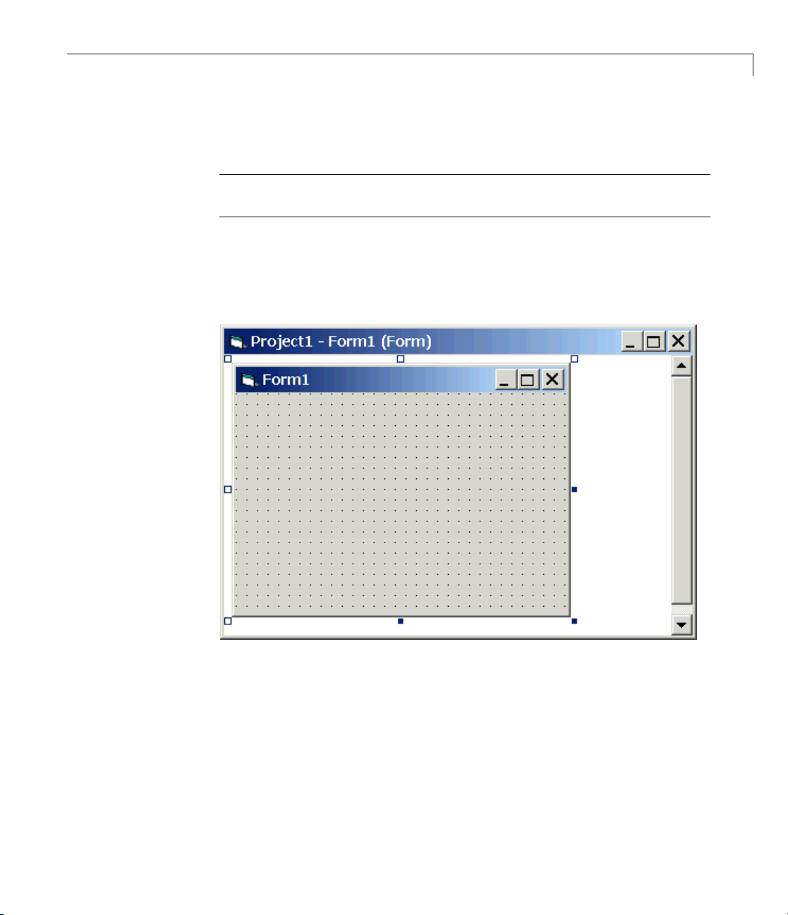
Example Visual Basic®GUI Using COM Objects
The New Project dialog box opens.
Note Be sure to open the Microsoft Visual Basic project from the project
directory itself, not from Microsoft Visual Basic.
4 Select Standard EXE,andthenclickOK.
The Microsoft Visual Basic Integrated Development Environment opens
with a blank form.
5 From the File menu, click Save Project As and enter a filename for the
form and the project. For example, for the form, enter
_tank1_COM.frm
xpc
At the p roject prompt, enter
c_tank1_COM.vbp
xp
3-21
Page 68

3 xPC Target™ COM API
Referencing the xPC Target COM API and
Model-Specific COM Libraries
You need to reference the xPC Target COM API and model-specific COM
libraries s o that Microsoft Visual Basic will use the m in the current project.
Assuming that you created the Visual Basic project as described in the
preceding procedure, reference the library as described in this procedure:
1 From the Project menu, click References.
The References dialog box opens.
2 Select the COM tab.
3 Scroll down the Component Name list to the bottom. Select the xPC
Target API COM Type Library check box.
4 Click Select.
3-22
Page 69

5 Click OK.
Example Visual Basic®GUI Using COM Objects
The xP C Target COM API Type library (xpcapiCOM.dll) is now available
for use in your project.
6 To add the model-specific COM library, click References again from the
Project menu.
The References dialog box opens.
7 Scroll to find your model name. Select the check box xpc_tank1COMiface
1.0TypeLibrary.
8 Click Select.
3-23
Page 70

3 xPC Target™ COM API
9 Click OK.
3-24
The mod
now ava
COM Sig
COM Pa
objec
use the xPC Target COM API is an add-on to Visual Basic, it might
Beca
help
the C
es you through using Visual Basic to create a project for the
guid
xpc_tank1) model.
or (
el-specific COM API Type Library (
ilable for use in your project. Sections “Viewing Model-Specific
nal Object Classes” on page 3-25 and “Viewing Model-Specific
rameter O bject Classes” on page 3 -26 describe ho w to look at class
ts.
to know a bit about Visual Basic before going much farther wi th using
OM API. The section “Creating the Graphical Interface” on page 3-27
xpc_tank1COMiface.dll)is
xpctank
Page 71

Example Visual Basic®GUI Using COM Objects
Viewing Model-Specific COM Signal Object Classes
After you create a V isual Basic project and reference the xPC Target COM
API and model-sp ecif ic COM libraries, you can use the Visual Basic Object
browser (click the View menu and select Object Browser)tolookatthe
objects for the
1 From the View menu, select Object Browser.
A dialog box pops up with a drop-down list containing all the type library
information for a project.
2 Select the drop-down list for the project/library.
Alistoftheprojectlibrariesappears.
xpctankbio or xpc_tank1bio class:
3 Select model_nameCOMIFACELib.
The classes in your model appear.
iew the objects of a class, select that class.
4 To v
3-25
Page 72

3 xPC Target™ COM API
The objects in your class appear.
The
xpctankbio (or xpc_tank1bio) class contains the function Init and
the two properties
•
water_level
• pump_valve
Viewing Model-Specific COM Parameter Object Classes
After you create a V isual Basic project and reference the xPC Target COM
API and model-sp ecif ic COM libraries, you can use the Visual Basic Object
browser (click the View menu and select Object Browser)tolookatthe
objects for the
1 From the View menu, select Object Browser.
A dialog box pops up with a drop-down list containing all the type library
information for a project.
xpctankpt or xpc_tank1pt class:
3-26
2 Select the drop-down list for the project/library.
Alistoftheprojectlibrariesappears.
3 Select model_nameCOMIFACELib.
The classes in your model appear.
4 To view the objects of a class, select that class.
The objects in your class appear.
The
xpctankpt (or xpc_tank1pt) class contains the method Init and the
member properties
•
pump_switch
• upper_water_level
• lower_water_level
• pump_flowrate
Page 73

Example Visual Basic®GUI Using COM Objects
• water_level
• drain_valve
Creating the Graphical Interface
Forms are the foundation for creating the interface of a Visual Basic
application. You can use forms to add windows and dialog boxes to your
Visual Basic application. You can also u se them as containers for items that
are not a visible part of the application’s interface. For example, you might
have a form in your application that holds a timer object.
The first step in building a Visual Basic application is to create the forms that
are the basis for your application’s interface. Then you create the objects that
make up the interface on the forms. This section assumes that you have a
Visual Basic project (see “Creating a New Microsoft
on page 3-20). For this first application, you will use four types of controls
from the toolbox:
• Button
®
Visual Basic Project”
• Timer
• Label
• Scrollbar
1 Open xpc_tank1_COM.vbp.
2 On the left, from the General tool panel, click and drag the Button icon
totheformtocreateabutton.
3 Repeat for a second button.
4 If you want to view signal data on the host, return to the General tool
panel and click and drag the Timer icon
ou want to view signal data on the host, add a Label control to the form.
5 If y
to the form to create a timer.
Return to the General tool panel and click and drag the Label icon
the form to create a label.
to
3-27
Page 74

3 xPC Target™ COM API
6 Ifyouwanttobeabletovarytheparameterinputtothetarget,return
to the General tool panel and click and drag the HScrollBar icon
to the form.
7 Next, name your new form objects. Right-click the first button and select
Properties. This bring s up the Properties dialog box. In the Caption box,
enter
Load. Repeat for the second button, but enter Start. Repeat for
the third button, but enter
Stop. (If you are unsure about how to work
with properties, refer to the procedure “Setting Properties” on page 3-29.)
After y ou name your new form objects and set whatever other parameters
you w ant (for example, if you use a timer you must increase the
Interval
parameter), you can write the code behind these objects using the Visual
Basiccodeeditorwindow(referto“WritingCode”onpage3-31).
If you added a scroll bar to your project, it should look similar to the figure
below.
3-28
If you added a timer and label to your project, it should look similar to
thefigurebelow.
Page 75

Example Visual Basic®GUI Using COM Objects
Note If you add a timer, remember to increase the interval of the timer to
a value greater than the default value of
Properties. This brings up the Properties dialog box. In the Interval box,
enter a value greater than
0, for example, 100.
0. Right-click the tim er and select
Setting Properties
This procedure describes how to set properties for the Visual B as ic objects you
created on your form. If you already know how to set properties for Visual
Basic objects, proceed to “Writing Code” on page 3-31.
3-29
Page 76

3 xPC Target™ COM API
The Properties window in the following figure provides an easy way to
set properties f or all objects on a form. To open the Properties window,
choose the Properties Window command from the View menu, click the
Properties Window button on the toolbar, or use the context menu for the
control.
3-30
The Properties window consists of the following elements:
• Object box — Displays the name of the object for which you can set
properties. Click the arrow to the right of the object box to display the
list of objects for the current form.
Page 77

Example Visual Basic®GUI Using COM Objects
• Sort tabs — Choose an alphabetic listing of properties or a hierarchical
view divided by logical categories, such as those dealing with appearance,
fonts, or position.
• Properties list — The left column displays all the properties for the selected
object. You can edit and view settings in the right column.
To set properties from the Properties window,
1 From the View menu, choose Properties,orclicktheProperties button
on the toolbar.
The Properties window displays the settings for the selected form or
control.
2 From the properties list, s elect the name of a property.
3 In the right column, type or select the new property setting.
Enumerated properties have a predefined list of settings. You can display
the list by clicking the down arrow at the right of the settings box, or you
can cycle through the list by double-clicking a list item.
You can also set object properties directly in the code by using the following
dot notation:
Object.propertyname=value.
Writing Code
The code editor window is where you write Visual Basic code for your
application. Code consists of language statements, constants, and
declarations. Using the code editor window , you can quickly view and edit
any of the code in your application.
The code editor window has three pane s. The top leftmost pane is the object
list box. It is a dropdown list that co nta ins all the form controls in your
project, plus a general section for generic declarations. The top rightmost
pane contains a procedure list box. For the selected or active control in the
object list box, the procedure list box displays the available procedures, or
events. Visual Basic predefines the possible procedures. The third pane
containsthecodefortheVisualBasicapplication. See the following figure for
asamplecodeeditorwindow.
3-31
Page 78

3 xPC Target™ COM API
3-32
In the gen
COM objec
followi
•
ng are the objects you need to declare:
xPCProt
runnin
brary. At a minimum, you must declare this object.
link li
•
xPCTar
ation. At a minimum, you must declare this object.
applic
•
•
•
ope
xPCSc
terfacing with xPC Target scopes. You need to declare a scope if you
for in
to acquire data from scopes o r display data on scopes.
want
l_namept
mode
meters.
para
el_namebio
mod
nals.
sig
eral declarations section, declare a reference to the xPC Target
ts that you are using to interface with the xPC Target objects. The
ocol
— Reference the classes corresponding to the target PC
g the target application and initialize the xPC Target API dynamic
get
— Reference the classes for interfacing with the target
— If the API application requires signal data, reference the class
— This is the COM object for tunable model/application
—ThisistheCOMobjectformodel/target application
Page 79

Example Visual Basic®GUI Using COM Objects
Creating the Gen
This procedure d
the
xpctank (or x
1 Double-click t
escribes how to create the general object declarations for
pc_tank1
he form or, from the View menu, select Code.
eral Declarations
) model:
The code editor window box opens for the control.
2 Select the General object.
3 Select Decla
rations in the procedure list box.
A template for the declarations procedure is now displayed in the code
editor window.
4 Enter declarations for the xPC Target COM objects you are using.
Public pro
Public ta
Public sc
5 Enter declarations for the model-specific COM objects you are using.
Public p
Public s
tocol_obj As xPCProtocol
rget_obj As xPCTarget
ope_obj As xPCScopes
arameters_obj As xpc_tank1pt
ignals_obj As xpc_tank1bio
Creating the Load Procedure
This pro cedure describes how to programaloadtargetapplication procedure
for the form. You might or might not want to allow users to download target
applications to the target PC. However, if you do want to allow this action,
you need to provide a control o n the GUI for the user to do so. “Creating
Event Procedures to Load Applications” on page 3-36 describes how to provide
such a control.
1 In the project window, double-click the Form object.
code editor window opens.
The
2 In the p rocedure list box, select Load.
3-33
Page 80

3 xPC Target™ COM API
3 Create and initialize the objects for the Load method in the form. Note that
the f ollowing code also checks that the initialization of the
protocol_obj
succeeds. If it does not succeed, an error message is returned and the
application will exit.
Private Sub Form_Load()
Set protocol_obj = New xPCProtocol
Set target_obj = N ew xPCTarget
Set scope_obj = Ne w xPCScopes
Set parameters_obj = New xpc_tank1pt
Set signals_obj = New xpc_tank1bio
stat = protocol_obj.Init
Ifstat<0Then
MsgBox("Could not load api ") 'We can no longer continue.
End
End If
stat = protocol_obj.RS232Connect(0, 0)
stat = target_obj.Init(protocol_obj)
stat = scope_obj.Init(protocol_obj)
stat = parameters_obj.Init(protocol_obj.Ref)
stat = signals_obj.Init(protocol_obj.Ref)
End Sub
3-34
YoucanaddmorecodetotheLoad method. This is the minimum code
you should enter for this method.
Page 81

Example Visual Basic®GUI Using COM Objects
Your code editor window should look similar to the following.
Creating Event Procedures
Code in a Visual Basic application is divided into smaller blocks called
procedures. Event procedures, such as those you create here, contain code
that mainly calls the xPC Target API component methods. For example, when
a u ser clicks a button, that action starts the x PC Target application.
This code is also responsible for the feedback action (such as enabling a
timer control, disabling/enabling controls) when an event occurs. An event
procedure for a control combines the control’s name (specified in the Name
property), an underscore (_), and the event name. For example, if you want
a command button named Command1 to invoke an event procedure when
it is clicked, call the procedure
illustrate how to create event procedures, using the
model as an example.
Command1_Click. The following procedures
xpctank (or xpc_tank1)
3-35
Page 82

3 xPC Target™ COM API
Creating Event Procedures to Load Applications
This procedure describes how to program the command button Command1
to load an application to the target PC through a serial connection. Provide
a procedure like this to allow users to download target applications to the
target PC.
1 Double-click the form or, from the View menu, select Code.
2 From the obje ct list box, select the name of an object in the active form.
(The active form is the form that currently has the focus.) For this example,
choose the command button Command1.
3 In the procedure list box, select the name of an event for the selected object.
Here, the
Click procedure is already selected because it is the default
procedure for a command button.
4 To load the target application, enter the path to the target application. If
thetargetapplicationisinthesamefolder as the API application, enter ".".
Enter the name of the target application without the extension.
stat = target_obj.LoadApp(".", "xpc_tank1")
When you are done, the contents of your code editor window should look
similar to the code below:
Private Sub Command1_Click()
stat = target_obj.LoadApp(".", "xpc_tank1")
End Sub
3-36
Page 83

Example Visual Basic®GUI Using COM Objects
CreatingEventProceduresto Start and Stop Applications
This pro cedure describes how to program the command buttons Command2
and Com mand3 to start and stop an application on a target PC:
1 If you are not already in the code editor window, double-click the form or,
from the View menu, select Code.
2 From the obje ct list box, select the name of an object in the active form.
(The active form is the form that currently has the focus.) For this example,
choose the command button Command2.
3 In the procedure list box, select the name of an event for the selected object.
Here, select the
4 To start the target application, select the StartApp method for the
command button Command2 (thisisthebuttonyounamed
stat = target_obj.StartApp
5 To stop the target application, select the StopApp method for the command
button Com mand3 (this is the button you named
the
Click procedure in the procedure list box.
Click procedure.
Start).
Stop). Be sure to select
stat = target_obj.StopApp
When you are done, the contents of your code editor window should look
similar to the code below:
Private Sub Command2_Click()
stat = target_obj.StartApp
End Sub
Private Sub Command3_Click()
stat = target_obj.StopApp
End Sub
CreatingEventProcedurestoVaryInputValues
You can provide controls to allow users to vary the parameters of their
applications. The Scroll procedure is one way of varying input. The following
code uses the Visual Basic
HScrollBar object to vary the water_level
3-37
Page 84

3 xPC Target™ COM API
parameter. It takes the value from the HScrollBar object and sends that
value to the target as a parameter change.
Note This section assumes that you have tagged block parameters and
created your own model-specific COM library. Refer to “Getting Parameter
IDs with the GetParamIdx Method” on page 3-41 for a descrip t io n of how to
manually perform the equivalent of using tagged parameters.
1 If you are not already in the code editor window, double-click the form or,
from the View menu, select Code.
2 From the obje ct list box, select the name of an object in the active form.
(The active form is the form that currently has the focus.) For this example,
select the
HScroll1 object.
The cursor jumps to the
3 In the procedure list box, select the name of an event for the selected object.
Here, select the
4 Declare the slideVal variable as a double. The slideVal variable will
Scroll procedure.
HScroll1 object template of the code editor window.
contain the value of the scrollbar.
Dim slideVal(0) As Double
5 Assign to the slideVal variable the result of CDbl.TheCDbl function
reads the value of an object property. In this example, the object
HScroll1
has the property slideVal(0). CDbl reads the value of HScroll1.Value
and returns that value to slideVal.
slideVal(0) = CDbl(HScroll1.Value)
6 Set the value of water_level to the scroll bar value slideVal,whichis
from
HScrollBar.TheCOM object target_obj has the method SetParam,
which has the syntax
references
parIdx from the model-specific COM object (type xpc_tank1pt).
To set the value of
SetParam and continue typing. A list of the parameters you tagged in
SetParam(parIdx, new parVal). The SetParam method
water_level to the scroll bar value slideVal,select
3-38
Page 85

Example Visual Basic®GUI Using COM Objects
the Simulink model then pops up, and you can select the parameter
water_level and continue typing.
The call to
stat = target_obj.SetParam(parameters_obj.water_level,
slideVal)
SetParam should look like the following:
When you are done, the contents of your code editor window should look
similar to the code below:
Private Sub HScroll1_Scroll()
Dim slideVal(0) As Double
slideVal(0) = CDbl(HScroll1.Value)
stat = target_obj.SetParam(parameters_obj.water_level,
slideVal)
End Sub
Creating Event Procedures to Display Signal Values at the Host
You can provide controls to v iew signal values at the host. To do this, use a
combination of the timer and label controls. The following code uses the Visual
Basic timer control to display the
Note This section assumes that you have tagged signals and created your
own model-specific COM library. Refer to “Getting Signal IDs with the
GetSignalIdx Method” on page 3-43 for a description of how to manually
perform the equivalent of using tagged signals.
water_level signal on the label control.
Before you start, check that the Timer1 Interval property is greater than 0.
1 From the object list box, select the Timer1 obje ct.
2 Assign to the Label1.Caption object the value of the water_level signal.
The
COM object target_obj has the method GetSignal(sigNum). Reference
the
sigNum parameter by passing it signals_obj.water_level.TheCStr
function converts the returned value to a string so that it can be displayed
on the
Label1 object.
3-39
Page 86

3 xPC Target™ COM API
When you are done, the contents of your code editor window should look
similar to the code below:
Private Sub Timer1_Timer()
Label1.Caption =
CStr(target_obj.GetSignal(signals_obj.water_level))
End Sub
Note Although you add both a timer and label object to the Visual Basic
application, only the label appears o n the GUI itself when the Visual Basic
application is run. The timer is not visible.
Creating Unload and Termination Procedures
You should write Form Unload and Termination procedures to ensure that
users are able to stop and unload the application appropriately, and to close
the communication between the host PC and target PC.
3-40
Note Provide Form Unload and Termination procedures to ensure that the
communication channel between the host PC and target PC properly closes
between each run of the GUI application.
The Terminate procedure controls the behavior of the Visual Basic Run
menu End option. The Unload procedure controls the behavior of the Visual
Basic Close button.
1 From the object list box, select the Form object.
2 From the procedure list box, select Terminate.
3 Youaregoingtoclosetheconnection with the target PC, so type
protocol_obj and select the Close method for that object.
protocol_obj.Close
4 From the procedure list box, select Unload.
Page 87

Example Visual Basic®GUI Using COM Objects
5 Repeat step
When you are done, the contents of your code editor window should look
similar to the code below:
Private Sub Form_Terminate()
protocol_obj.Close
End Sub
Private Sub Form_Unload(Cancel As Integer)
protocol_obj.Close
End Sub
Referencing Parameters and Signals Without Using
Tags
Thesamplecodein“CreatingEventProcedures to Vary Input Values” on
page 3-37 and “Creating Event Procedures to Display Signal Values at the
Host” on page 3-39 illustrates how to reference parameters that you tagged
before building the Simulink model. This section describes how to reference
these sam e parameters a nd signals from the CO M API application code if you
did not opt to tag signals and parameters.
Getting Parameter IDs with the GetParamIdx Me thod
When working with parameters in the context of varying input values, you
use the
the syntax
where parIdx is the identifier that corresponds to the parameter you want to
set. To obtain the parameter ID,
GetParamIdx method. This method has the syntax
The following procedure describes how to obtain the appropriate GetParamIdx
block name and parameter name for the Visual Basic HScrollBar object. You
need to reference the block name and parameter from the
file.
SetParam and GetParamIdx methods. The SetParam method has
SetParam(ByVal parIdx As Integer, ByRef newparVal As
System.Array) As Long
parIdx,forSetParam, you need to call the
GetParamIdx(ByVal blockName As String, ByVal par amNa me As
String) As Long
model_namept.m
3-41
Page 88

3 xPC Target™ COM API
1 Open a DOS window.
2 Change the directory to the directory that contains your prebuilt model.
3 Open the file model_namept.m. For example, you can use the notepad
text editor.
notepad xpc_tank1pt.m
The editor opens for that file. If you are not in the directory in which the
xpc_tank1pt.m file resides, be sure to type the full path for xpc_tank1pt.m.
4 Search for and copy the string for the block of the parameter you want to
reference. For the
xpc_tank1 example, search for the SetPoint block if you
want to reference the water level. For example,
SetPoint
5 Return to the code e ditor window for your project.
3-42
6 InthelinethatcontainsthecalltoGetPara mIdx , enter the path for the
blockName variable.
7 Return to the editor window for model_namept.m.
8 Search for and copy the string for the name of the parameter you are
interested in. For example,
Value
If you do not know the name of the block parameter you are interested
in, refer to “Model and Block Parameters” of the Simulink Reference
documentation.
9 Return to the code editor window for your project.
10 InthelinethatcontainsthecalltoGetPara mIdx , enter the path for the
paramName variable. For example,
stat = target_obj.SetParam(target_obj.GetParamIdx
("SetPoint", "Value"), slideVal)
Page 89

Example Visual Basic®GUI Using COM Objects
When you are done, the contents of your code editor window should look
similar to the code below:
Private Sub HScroll1_Scroll()
Dim slideVal(0) As Double
slideVal(0) = CDbl(HScroll1.Value)
stat =
target_obj.SetParam(target_obj.GetParamIdx
("SetPoint", "Value"), slideVal)
End Sub
Note, if you want to retrieve the full block path and parameter name of a
block, use the
GetParamName method. The GetParamName method returns
a variant data type object with two elements. The first element contains
the full block path, the second element contains the parameter name. The
following example illustrates how to use the
GetParamName method to get
the block path and parameter name:
Dim Pname As Variant
Pname=xpc_tank1.GetParamName(GetParamIdx(Idx)
BlockPathString=CStr(Pname(0))
ParameterNameString=CStr(Pname(1))
In this example,
•
Idx is the index to a parameter.
BlockPathString contains the full block path string.
•
ParameterNameString contains the parameter name string.
•
Getting Signal IDs with the GetSignalIdx Method
When working with signals in the context of displaying signal values, you
use the
the syntax
where sigNum is the identifier that corresponds to the signal you want to set.
GetSignal and GetSignalIdx methods. The GetSignal method has
GetSignal(sigNum As Long) As Double
3-43
Page 90

3 xPC Target™ COM API
To obtain the signal ID sigNum for Ge tSig nal,youcalltheGetSignalIdx
method. This method has the syntax
GetSignalIdx(sigName As String) As Lo ng
The following procedure describes how to obtain the appropriate
GetSignalIdx block name for the Visual Basic timer object. You need to
reference the block nameandsignalfromthe
1 Open a DOS window.
2 Change the directory to the directory that contains your prebuilt model.
3 Open the file model_namebio.m. For example,
notepad xpc_tank1bio.m
model_namebio.m file.
The editor opens for that file. If you are not in the directory in which
the
xpc_tank1bio.m file resides, be sure to type the full path for
xpc_tank1bio.m.
3-44
4 Search for and copy the string for the b lock of the signal you w a nt to
reference. For the
xpc_tank1 example, search for the TankLevel block to
reference the tank level. For example,
TankLevel
5 Return to the code e ditor window for your project.
6 InthelinethatcontainsthecalltoGetSignalIdx, enter the path for the
SigName variable.
When you are done, the contents of your code editor window should look
similar to the code below:
Private Sub Timer1_Timer()
Label1.Caption =
CStr(target_obj.GetSignal(target_obj.GetSignalIdx("TankLevel"
)))
End Sub
Page 91

Example Visual Basic®GUI Using COM Objects
Testing the Visu
While creating y
application is p
while still in t
can click the Ru n button
1 If you have the MATLAB interface and a target object connected, close the
port. For example, at the MATLAB command line, type
tg.close
2 From within the project, go to the Run menu.
3 Select Star
applicati
the applic
The form y
only one v
applica
the task
Note If
betwee
close t
doing
“Crea
to w ri
contr
tion from within Visual Basic, you can click the End button
bar. Alternatively, you can go to the Run menu and select End.
your Visual Basic application opens a communication channel
n the host PC and the target PC for the target application, be sure to
hat open channel between test runs of the Visual Basic application. Not
so can cause subsequent runs of the Visual Basic ap p lication to fail.
ting Unload and Termination Procedures” on page 3-40 describes how
te a procedure to disconnect from the target PC. If you want to return
oltotheMATLABinterface,besuretoclosetheVisualBasicprojectfirst.
our Visual Basic application, you might want to see how the
rogressing. Visual Basic allows you to run your application
he Visual Basic project. From the Visual Basic task bar, you
t or Start with Full Compile.TheStart option starts your
on immediately. The Start with Full Compile option starts
ation after compilation.
ou are working on pops up. Test your application. Ensure that
ersion of the application is running at any given time. To stop the
al Basic Application
. Alternatively, you can follow the procedure:
from
ding the Visual Basic Application
Buil
eryoufinishdesigning,programming, and testing your Visual Basic
Aft
application, build your application. You can later distribute the GUI
GUI
lication to users, who can then use it to work with target applications.
app
om within the project, go to the File menu.
1 Fr
3-45
Page 92

3 xPC Target™ COM API
2 Select Make project_name_COM.exe,whereproject_name is the name of
the Visual Basic project you have been working on.
3 At the pop-up b ox , select the directory in which you want to save the
executable. Optionally, you can also rename the executable.
The compiler generates the
directory.
project_name_COM.exe file in the specified
Deploying the API Application
This section assumes that you have built your xPC Target application and
your Visual Basic xPC Target COM GUI application. If you have not yet
done so, refer to “Creating the Target Application and Model-Specific COM
Library” on page 3-14 and “Bu ildin g the Visual Basic Application” on page
3-45, respectively.
When distributing the Visual Basic model application to users, provide the
following files:
•
project_name_COM.exe, the executable for the Visual Basic application
model_name.dlm
•
Provide model_name.dlm if you expect the user to download the target
application to the target PC. Ensure that you have enabled an application
load event on the Visual Basic interface (refer to “Creating the Load
Procedure” on page 3-33).
If you expect that the target application is already loaded on the target PC
when the user runs the Visual Basic GUI application, you m ight not want
him or her to be able to load the target application to the target PC.
3-46
•
model_nameCOMiface.dll, if you tag the signals and parameters in the
model
•
xpcapiCOM.dll, the xPC Target COM API dynamic link library
xpcapi.dll, the xPC Target API dynamic link library
•
Havetheuserensurethatallthefilesarelocatedinthesamedirectorybefore
he or she executes the Visual Basic application.
Page 93

Example Visual Basic®GUI Using COM Objects
You must also ensure that the user knows how to register the
application-dependent dynamic link libraries (refer to “Registering Dependent
Dynamic Link Libraries” on page 3-47).
To run the application and download an xPC Target application, users need
to have
project_name_COM.exe and model_name.dlm, if provided, in the
same directory.
Registering Dependent Dynamic Link Libraries
This procedure uses xpc_tank1 as an exampl e.
1 Open a DOS window.
2 Change the directory to the directory containing the API application files.
3 From the directory in which xpcapiCOM.dll resides, register the x PC
Target COM API DLL by typing
regsvr32 xpcapiCOM.dll
DOS displays the message
DllRegisterServer in xpcapiCOM.dll succeeded
Creating a New Visual Basic Project Using Microsoft
Visual Studio 8.0
The procedures for the preceding topics apply to Microsoft Visual Studio
6.0 (“Creating a New Microsoft
procedures to use Microsoft Visual Studio 8.0is similar, with the following
exceptions.
• You can open a Micro soft Visual Studio 6.0 project under Microsoft Visual
Studio .NET 2003. Microsoft Visual Studio .NET 2003 automatically
converts the project.
• If you first create a new Visual Basic project, select Windows Application
as the template.
• When referencing the xPC Target COM API and model-specific COM
libraries, do the following
®
Visual Basic Project” on page 3-20). The
3-47
Page 94

3 xPC Target™ COM API
1 From the Project menu, click Add Reference.
The Add Reference dialog box opens.
2 Select the COM tab.
3 Scroll down the Component Name list to the bottom and select the
xPC Target API COM Type Library item.
4 Click Select.
xPC Target API COM Type Library appears in the Selected
Components pane.
5 Click OK.
• When creating a reference to the xPC Target interface objects, include the
COM library. The following illustrates example code on how to reference
these objects in Microsoft Visual Studio .NET 2003 and Microsoft Visual
Studio6.0:
Microsoft Visual Studio .NET 2003
3-48
Public protocol_obj As XP CAPICOMLib.xPCProtocol
Public target_obj As XPCAP ICOMLib.xPCTarget
Public scope_obj As XPCAPI COMLib.xPCScopes
Microsoft Visual Studio 6.0
Public protocol_obj As xP CProtocol
Public target_obj As xPCTa rget
Public scope_obj As xPCSco pes
• When creating an instance of the xPC Target interface objects, include
the COM library. T he following illustrates example code on how to create
an instance of these objects in Microsoft Visual Studio .NET 2003 and
Microsoft Visual Studio 6.0:
Microsoft Visual Studio .NET 2003
protocol_obj = New XPCAPI COMLib.xPCProtocol
target_obj = New XPCAPICOMLib.xPCTarget
scope_obj = New XPCAPICOMLib.xPCScopes
Page 95

Example Visual Basic®GUI Using COM Objects
Microsoft Visual Studio 6.0:
Set protocol_obj = New xPCProtocol
Set target_obj = New xPCTarget
Set scope_obj = New xPCScopes
• Microsoft Visual Studio .NET 2003 builds applications into the bin
directory of your project area. You cannot choose another location to place
your executable.
• When distributing the Visual Basic model application to users, p rovide the
following files in addition to those listed in “Deploying the API Application”
on page 3-46:
- Interop.mode l_na meACOMIFACELib.dll
- Interop.XPCA PICO MLib.dll
3-49
Page 96

3 xPC Target™ COM API
3-50
Page 97

xPC Target COM API
Demos and Scripts
• “Microsoft®Visual Basic .NET Demo” on page 4-2
®
• “Microsoft
• “Tcl/Tk Scripts” on page 4-8
Visual Basic 6.0 Demo” on page 4-5
4
Page 98

4 xPC Target™ COM API Demos and Scripts
Microsoft V isual Basic .NET Demo
In this section...
“Introduction” on page 4-2
“Before Starting” on page 4-3
“Accessing the Demo Project Solution” on page 4-3
“Rebuilding the Demo Project Solution” on page 4-4
“Using the Demo Executable” on page 4-4
Introduction
To help you better understand and quickly begin to use COM
API functions to create custom GUI applications, the xPC Target
environment provides a number of API demos and scripts in the
C:\matlabroot\toolbox\rtw\targets\xpc\api directory. This topic briefly
describes those demos and scripts.
4-2
The Microsoft Visual Basic .NET demo illustrates how to create a custom
GUI that connects to a target PC with a downloaded target application. The
solution file for this demo is located in
C:\matlabroot\toolbox\rtw\targets\xpc\api\VBNET\SigsAndParamsDemo
• bin — C ontains the executable for the demo project and the xpcapi.dll file
Demo.sln — Contains a solution file for the Demo project
•
The
Demo.sln file contains all the Visual Basic .NET files to run the windows
form application. This demo is a functional application that you can use as a
template to create your own custom GUIs.
The COM API example from “Example Visual Basic GUI Using COM Objects”
on pag e 3-4 is a simple GUI that illustrates so m e basic concep t s for creatin g a
GUI with the COM API. The
illustrates how to create a GUI similar to the xPC Target Explorer. The
solution is fully commented.
Demo s olution is a more advanced example that
Demo
Page 99

Microsoft®Visual B asic®.NET Demo
This demo illustrates how you can use the COM A P I to create a GUI that
• Connects to the target PC via an RS-232 or TCP/IP connection
• Starts and stops the target application loaded on the target P C
• Retrieves and lists all the sign a ls in the target application
• Displays the value of a selected signal
• Retrieves and lists all the parameters in the target application
• Change the values of t h e parameters
Before Starting
To use the Demo solution, you need
• A target PC running a current xPC Target kernel
• A host PC running the MATLAB software interface, connected to the target
PCviaRS-232orTCP/IP
• A target application loaded on the target PC
The xPC Target product ships with an executable version of the demo. If you
want to rebuild the
GUIs like this one, you need Microsoft Visual Basic .NET installed on the
host PC.
Note The xPC Target software allows you to create applications, such as
GUIs, to interact with a target PC with COM API functions. Chapter 3, “xPC
Target COM A PI” describes this in detail. To deploy a GUI application to
other host PC systems that do not have your licensed copy of the xPC T arget
product, you need the xPC Target Embedded Option™. If you do not have the
xPC Target Embedded Option and would liketodeployyourGUIapplication,
contact your MathWorks™ representative.
Demo solution, of if you want to write your own custom
Accessing the Demo Project Solution
To access the Demo solution,
4-3
Page 100

4 xPC Target™ COM API Demos and Scripts
1 Copy the contents of the VBNET directory to a writable directory of your
choice.
2 Change directory to the one that contains your copy of the Demo solution.
3 Double-click demo.sln.
The Microsoft Development Environment for Visual Basic application
starts.
4 In the Solution Explorer pane, double-click Form1.vb to display the
Demo solution form.
The form is displayed. You can inspect the layout of the demo.
5 To inspect the form code, select the View menu Code option.
The Visual Basic code for the form is displayed.
Rebuilding the Demo Project Solution
To rebuild the Demo solution,
4-4
1 Double-click demo.sln.
The Microsoft Development Environment for Visual Basic application
starts.
2 Select the Build menu Build Solution option.
Using the Demo Executable
To use the Demo solution exe cutable ,
1 Change directory to the one that contains your copy of the Demo solution.
2 Change directory to the bin directory.
3 Double-click Demo1.exe.
The GUI is displayed.
 Loading...