

Page 1

Video and Image Pro
User’s Guide
cessing Blockset™ 3
Page 2

How to Contact The MathWorks
www.mathworks.
comp.soft-sys.matlab Newsgroup
www.mathworks.com/contact_TS.html Technical Support
suggest@mathworks.com Product enhancement suggestions
bugs@mathwo
doc@mathworks.com Documentation error reports
service@mathworks.com Order status, license renewals, passcodes
info@mathwo
com
rks.com
rks.com
Web
Bug reports
Sales, prici
ng, and general information
508-647-7000 (Phone)
508-647-7001 (Fax)
The MathWorks, Inc.
3 Apple Hill Drive
Natick, MA 01760-2098
For contact information about worldwide offices, see the MathWorks Web site.
Video and Image Processing Blockset™ User’s Guide
© COPYRIGHT 2004–20 10 by The MathWorks, Inc.
The software described in this document is furnished under a license agreement. The software may be used
or copied only under the terms of the license agreement. No part of this manual may be photocopied or
reproduced in any form without prior written consent from The MathW orks, Inc.
FEDERAL ACQUISITION: This provision applies to all acquisitions of the Program and Documentation
by, for, or through the federal government of the United States. By accepting delivery of the Program
or Documentation, the government hereby agrees that this software or documentation qualifies as
commercial computer software or commercial computer software documentation as such terms are used
or defined in FAR 12.212, DFARS Part 227.72, and DFARS 252.227-7014. Accordingly, the terms and
conditions of this Agreement and only those rights specified in this Agreement, shall pertain to and govern
theuse,modification,reproduction,release,performance,display,anddisclosureoftheProgramand
Documentation by the federal government (or other entity acquiring for or through the federal government)
and shall supersede any conflicting contractual terms or conditions. If this License fails to meet the
government’s needs or is inconsistent in any respect with federal procurement law, the government agrees
to return the Program and Docu mentation, unused, to The MathWorks, Inc.
Trademarks
MATLAB and Simulink are registered trademarks of The MathWorks, Inc. See
www.mathworks.com/trademarks for a list of additional trademarks. Other product or brand
names may be trademarks or registered trademarks of their respective holders.
Patents
The MathWorks products are protected by one or more U.S. patents. Please see
www.mathworks.com/patents for more information.
Page 3

Revision History
July 2004 First printing New for V ersion 1.0 (Release 14)
October 2004 Second printing Revised for Version 1.0.1 (Release 14SP1)
March 2005 Online only Revised for Version 1.1 (Release 14SP2)
September 2005 O nline only Revised for Version 1.2 (Release 14SP3)
November 2005 Online only Revised for Version 2.0 (Release 14SP3+)
March 2006 Online only Revised for Version 2.1 (Release 2006a)
September 2006 O nline only Revised for Version 2.2 (Release 2006b)
March 2007 Online only Revised for Version 2.3 (Release 2007a)
September 2007 O nline only Revised for Version 2.4 (Release 2007b)
March 2008 Online only Revised for Version 2.5 (Release 2008a)
October 2008 Online only Revised for Version 2.6 (Release 2008b)
March 2009 Online only Revised for Version 2.7 (Release 2009a)
September 2009 O nline only Revised for Version 2.8 (Release 2009b)
March 2010 Online only Revised for Version 3.0 (Release 2010a)
Page 4

Page 5

Getting Started
1
Product Overview ................................. 1-2
Contents
Installation
Installing the Video and Image Processing Blockset
Software
Required Products
Related P roducts
Product Demos
Demos in the Help Browser
Demos on the Web
Demos on MATLAB Central
Working with the Documentation
Viewing the Documentation
Printing the Documentation
Using This Guide
Key Blockset Concepts
Image Types
VideointheVideoandImageProcessingBlockset
Blocks
Defining Intensity and Color
Color Image Processing
Coordinate System s
Image Data Stored in Column-Major Format
Sample Time
Video Duration and Simulation Time
Acceleration Modes
Strategies for Real-Time Video Processing
Code Generation
....................................... 1-3
....................................... 1-3
................................. 1-4
.................................. 1-4
.................................... 1-5
......................... 1-5
................................. 1-9
......................... 1-10
................... 1-11
......................... 1-11
......................... 1-12
................................. 1-12
............................. 1-15
..................................... 1-15
........................................ 1-16
........................ 1-16
............................. 1-17
............................... 1-24
..................................... 1-26
................. 1-27
................................ 1-28
............. 1-29
.................................. 1-31
........... 1-26
Block Data Type Support
........................... 1-33
v
Page 6

Image Credits ..................................... 1-34
Importing and Exporting Images and Video
2
Batch Processing Image Files ....................... 2-2
Working with Live Video
Working with Multimedia Files
Blocks That Support Multimedia Files
Importing and Viewing Multimedia Files
Exporting to Multimedia Files
Working with AVI Files
Working with Audio
Working with MATLAB Workspace Variables
How to Import MATLAB Workspace Variables
........................... 2-7
..................... 2-8
................ 2-8
.............. 2-8
....................... 2-11
............................ 2-14
............................... 2-38
........ 2-43
......... 2-43
Viewing Video
3
Viewing Video Files ................................ 3-2
Viewing Video Signals in Simulink
Using the Video Viewer Block
Using the To Video Display B lock
Using the MPlay GUI
.............................. 3-3
.................. 3-3
....................... 3-3
.................... 3-3
vi Contents
Viewing Video File Frames
......................... 3-22
Page 7

Analysis and Enhancement
4
Feature Extraction ................................ 4-2
Finding Edges in Images
Finding Lines in Images
Measuring an Angle Between Lines
........................... 4-2
............................ 4-9
.................. 4-18
Image E nhancement
Sharpening and Blurring an Image
Removing Salt and Pepper Noise from Images
Removing Periodic Noise from Video
Adjusting the Contrast in Intensity Images
Adjusting the Contrast in Color Images
Template Matching
Using the Template Matching Block
Video Stabilization
Panorama Creation
Pixel Statistics
Blocks That Compute Pixel Statistics
Finding the Histogram of an Image
5
nsity to Binary Conversion
Inte
view of Intensity and Binary Images
Over
esholding Intensity Images Using Relational
Thr
rators
Ope
esholding Intensity Images Using the Autothreshold
Thr
ck
Blo
............................... 4-30
................... 4-30
.......... 4-39
.................. 4-45
............ 4-54
............... 4-61
................................ 4-67
.................. 4-67
................................ 4-71
................................ 4-72
.................................... 4-73
................. 4-73
................... 4-73
Conversions
.....................
..............
......................................
.........................................
5-2
5-2
5-2
5-7
lor Space Conversion
Co
erview of Color Space Conversion Block
Ov
onverting Color Information fro m R’G’B’ to Intensity
C
............................
.............
...
555
14
14
-14
vii
Page 8

Chroma Resampling ............................... 5-19
Geometric Transformation
6
Geometric Transformation Interpolation Methods .... 6-2
Overview o f Interpolation Methods
Nearest N eighbor Interpolation
Bilinear Interpolation
Bicubic Interpolation
.............................. 6-3
.............................. 6-4
................... 6-2
...................... 6-2
Rotating an Image
Resizing an Image
Cropping an Image
................................. 6-6
................................. 6-14
................................ 6-20
Morphological Operations
7
Overview of Morphology ........................... 7-2
Counting Objects in an Image
Correcting for Nonuniform Illumination
...................... 7-3
............. 7-10
Example Applications
viii Contents
8
Pattern Matching .................................. 8-2
Overview of Pattern Matching
....................... 8-2
Page 9

Tracking an Object Using Correlation ................. 8-2
Motion Compensation
Image Compression
Overview o f Image Compression
Compressing an Image
Viewing the Compressed Image
.............................. 8-10
................................ 8-12
..................... 8-12
............................. 8-12
...................... 8-18
Getting Started with System Objects
9
What Are System Objects? .......................... 9-2
Setting Up and Running System Objects
Creating an Instance of a System Object
Using Methods to Run System Objects
Finding Help and Demos for System Objects
Using System Objects with the Embedded MATLAB
Subset
Considerations for Using System Objects with the
Using System Objects with Embedded MATLAB Coder
Using System Objects with the Embedded MATLAB
Using System Objects with Embedded MATLAB MEX
.......................................... 9-9
Embedded MATLAB Subset
Function Block
................................. 9-12
....................... 9-9
............. 9-3
............... 9-3
................ 9-6
........... 9-8
.. 9-11
... 9-12
10
Using Video and Image Processing System
What Are Video and Image Processing System
Objects?
........................................ 10-2
Objects
ix
Page 10

Generating Code for Video and Image Processing
System Objects
.................................. 10-3
Working with Fixed-Point Data
Working with Fixed-Point Data
Example: Using System Objects in Video and Image
Processing Applications: Marking a Region of
Interest
......................................... 10-9
..................... 10-5
...................... 10-5
Index
x Contents
Page 11

Getting Started
1
The Video and Image Processing Blockset™ software is a tool for processing
images and video in the Simulink
introduction to the Video and Image Processing Blockset software, its product
requirements, and its documentation.
• “Product Overview” on page 1-2
• “Installation” on page 1-3
• “Product Demos” on page 1-5
• “Working with the Documentation” on page 1-11
• “Key Blockset Concepts” on page 1-15
• “Block Data Type Support” on page 1-33
• “Image Credits” on page 1-34
®
environment. This chapter provides an
Page 12

1 Getting Started
Product Overview
Video and Image Processing Blockset providesalgorithmsandtoolsforthe
design and simulation of video processing, image processing, and computer
vision systems. You can process video and image data to solve problems
such as noise, low contrast, out-of-focus optics, and artifacts resulting from
interlaced video. You can then perform tasks such as motion analysis, object
detection and tracking, video stabilization, and disparity estimation for stereo
vision. Most algorithms and tools are available as both System objects (for
use in MATLAB®) and blocks (for use in Simulink®).
Tools for multimedia file I/O, video display, drawing graphics, and compositing
enable you to visualize, simulate, and evaluate d esign alternatives. For
embedded system design and rapid prototyping, the blockset supports
fixed-point arithmetic, C-code generation, and implementation on embedded
hardware.
1-2
Page 13

Installation
In this section...
“Installing the Video and Image Processing Blockset Software” on page 1-3
“Required Products” on page 1-4
“Related Products” on page 1-4
Installing the Video and Image Processing Blockset
Software
Before you begin working with theVideoandImageProcessingBlockset
software, you need to install the product on your computer.
Installation from a DVD
Video and Image Processing Blockset blocks follow the s am e installation
procedure as the MATLAB
®
toolboxes:
Installation
1 Start the MathWorks™ installer.
2 When prompted, select the Product check boxes for the products you
want to install.
The doc
umentation is installed along with the products.
Installation from a Web Download
You ca
Math
n use your MathWorks Account to download products from the
Works Web site:
1 Navi
2 Click Download products.
3 Log in to the system using your MathWorks Account e-mail and password.
4 Se
gate to
If you do not have a MathWorks Account, you can create one from this
Web page.
lect your platform and the products you want to install.
http://www.mathworks.com/web_downloads/.
1-3
Page 14

1 Getting Started
5 Follow the instructions on the Download and Install screen, which
describe how to download the product(s) and the installer.
6 Double-click the Installer.exe file to run the installer.
7 When prompted, enter your Personal License Password.
8 Select the Product check boxes for the products you want to install.
The documentation is installed along with the products.
Required Products
The Video and Image Processing Blockset software is part of a
family of products from The MathWorks™. You need to install
several products to use the Video and Image Processing Blockset
software. For more information, see the MathWorks Web site at
http://www.mathworks.com/products/viprocessing/requirements.jsp.
Related Products
The MathWorks provide several products that are relevant to the kinds of
tasks you can perform with the Video and Image Processing Blockset software.
1-4
For more information about any of these products, see either
• The online documentation for that product if it is installed on your system
• The MathWorks Web site, at
http://www.mathworks.com/products/viprocessing/related.jsp
Page 15

Product Demos
In this section...
“Demos in the Help Browser” on page 1-5
“Demos on the Web” on page 1-9
“Demos on MATLAB Central” on p age 1-10
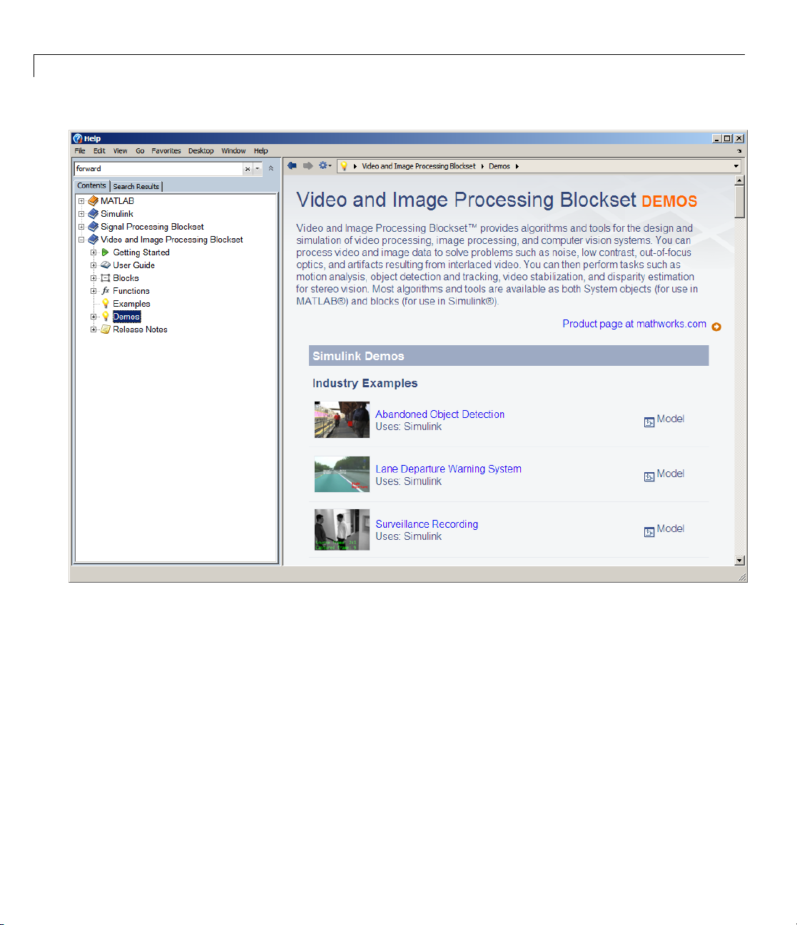
Demos in the Help Browser
You can find interactive Video and Image Processing Blockset demos in the
MATLAB Help browser. This example shows you how to locate and open a
typical demo:
1 To open the Help browser to the Demos tab, type doc at the MATLAB
command line.
2 Expand the Video and Image Processingnode in the Help browser, then
the Demos node.
Product Demos
1-5
Page 16
1 Getting Started
1-6
There are two entries under the Video and Image Processing Blockset
Demos node:
• Simulink Demos — Expand this entry to see a categorical list of
block-based V ideo and Image Processing Blockset demos.
• MATLAB Demos — Expand this entry to see a categorical list of Video
and Image Processing Blockset System object demos.
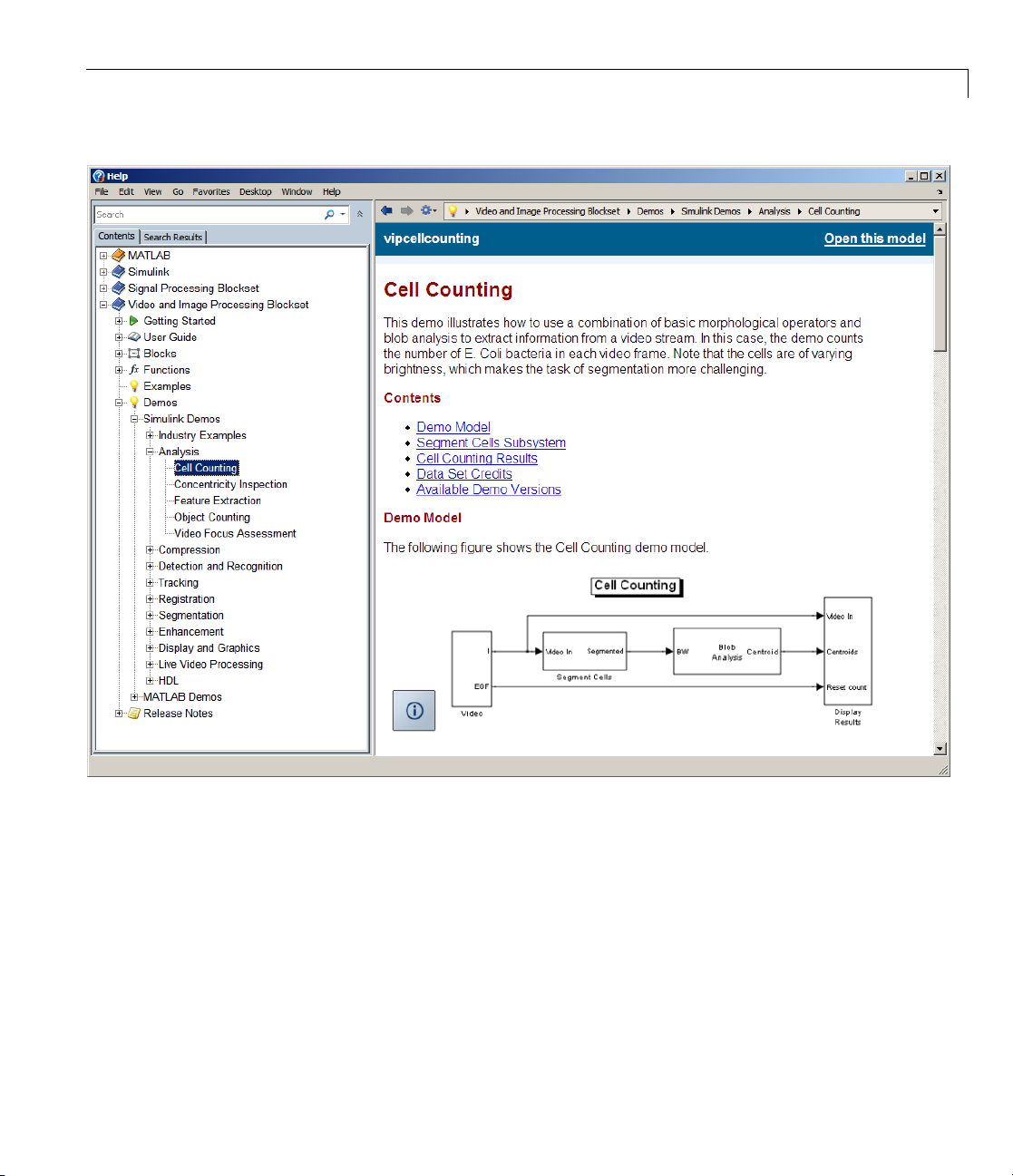
3 To view the description of the Simulink-based Cell Counting demo, which
demonstrates how to extract information from a video stream, expand the
Simulink Demos and Analysis,andthenclickCell Counting.
Page 17
Product Demos
a Click Open this model to display the Simulink model for Cell C ounting
demo. The model window opens.
1-7
Page 18

1 Getting Started
b Run the model by selecting Start from the Simulation menu in the
model w indow , or by clicking the start button from the toolbar.
1-8
c The Cell Counting dem o analyzes a binary video file. You will be
prompted to download the file, if it is unavailable in your folder system.
d TheresultsofthedemoappearintheResults graphical window.
4 To view a version of the Cell Counting demo that uses System objects in
MATLAB, expand the MATLAB Demos and Analysis,andthenclick
Cell Counting
Page 19

Product Demos
a Click Open videocellcounting.m in the Editor to display the System
object Cell Counting demo in the MATLAB editor.
b Run t
Dem
The
eo and Image Processing Blocksetsoftware. You can find these demos at
Vid
p://www.mathworks.com/products/viprocessing/demos.jsp
htt
he demo by clicking the Run toolbar button
emo appear in the Results graphical window.
the d
os on the Web
MathWorks Web site contains demos that show you how to use the
). The results of
.
1-9
Page 20

1 Getting Started
You can run these demos without having MATLAB or Video and Image
Processing Blockset software installed on your system.
Demos on MATLAB Central
The MATLAB Central website contains files, including demos, contributed
by users and developers of Video and Im age Processing Blockset software,
MATLAB, Simulink and other products. Contributors submit their files to
one of a list of categories. You can browse these categories to find submissions
that pertain to Video and Image Processing Blockset software or a specific
problem that you would like to solve. MATLAB Central is located at
http://www.mathworks.com/matlabcentral/.
1-10
Page 21

Working with the Documentation
In this section...
“Viewing the Documentation” on page 1-11
“Printing the Documentation” on page 1-12
“Using This Guide” on pag e 1-12
Viewing the Documentation
You can access the Video and Image Processing Blockset documentation using
files you installed on your system or from the Web using the MathWorks
Web site.
DocumentationintheHelpBrowser
This procedure shows you how to use the M AT LAB Help browser to view the
Video and Image Processing Blockset documentation installed on your system:
Working with the Documentation
1 In the MATLAB window, from the Help menu, click Product Help.The
Help browser opens.
2 From the list of products in the left pane, click Video and Image
Processing Blockset. In the right pane, the Help browser displays the
Video and Image Processing Blockset Roadmap page.
3 Under
Help b
The H
For m
the section titled Documentation Set, select User’s Guide.The
rowser displays the chapters of this manual.
elp b rowser also has a Demos tab where you can view product demos.
ore information, see “Product Demos” on page 1-5.
DocumentationontheWeb
can also view the documentation from the MathWorks Web site. The
You
umentation available on these Web pages is for the latest release,
doc
ardless of whether the release was distributed on a DVD or as a Web
reg
wnload:
do
1-11
Page 22

1 Getting Started
1 Navigate to the V id eo and Image Processing Blockset Product page at
http://www.mathworks.com/products/viprocessing/.
2 On the right side of the page, click the Documentation link. The Video
and Image Processing Blockset documentation is displayed.
Printing the Documentation
The documentation for the Video and Image Processing Blockset software is
also available in printable PDF format. You need to install Adobe Acrobat
Reader 4.0 or later to open and read these files. To download a free copy of
Acrobat Reader, see
The following procedure shows you how to view the documentation in PDF
format:
1 In the MATLAB window, from the Help menu, click Product Help.The
Help browser opens.
2 From the list of products in the left pane, click Video and Image
Processing Blockset. In the right pane, the Help browser displays the
Video and Image Processing Blockset Roadmap page.
http://www.adobe.com/products/acrobat/main.html.
1-12
3 Under the Printing the Documentation Set heading, click the links
to view PDF versions of the Video and Image Processing Blockset
documentation.
Using This Guide
To help you effectively read and use this guide, here is a brief description of
the chapters and a suggested reading path.
Expected Background
This m anual assumes that you are familiar with the following:
• The MATLAB language, to write scripts and functions with MATLAB code,
and to use functions with the command-line interface
• The Simulink environment, to create simple models as block diagrams
and simulate those models
Page 23

Working with the Documentation
What Chapter Should I Read?
Follow the procedures in this guide to become familiar with the blockset’s
functionality. The User’s Guide contains tutorial sections that are designed
to help you become familiar with using the Simulink and Video and Image
Processing Blockset software:
• Read Chapter 1, “Getting Started” to learn about the installation process,
the products required to run Video and Image Processing Blockset blocks,
and to view the Video and Image Processing Blockset demos.
• Read Chapter 2, “Importing and Exporting Images and Video” to
understand how video is interpreted by the Simulink blocks. Also, learn
howtobringvideodataintoamodel,displayitonyourmonitor,andexport
it to an AVI file.
• Read Chapter 3, “Viewing Video” to le arn how to use the MPlay GUI to
view videos that are represented as variables in the MATLAB workspace.
You can also learn how to use it to view video files or video signals in
Simulink models.
• Read Chapter 5, “Conversions” to learn how to convert an intensity image
to a binary image, how to convert color information between color spaces,
and how to downsample the chroma components of an image.
• Read Chapter 6, “Geometric Transformation” to understand how blocks in
the G eometric Transformations library interpolate values. You also learn
how to rotate, resize, and crop images.
• Read Chapter 7, “Morphological O perations” to learn about morphological
operations and which blocks can be used to perform them. For example,
you learn how to count objects in an image and correct for nonuniform
illumination.
• Read Chapter 4, “Analysis and Enhancement” to learn how to sharpen,
blur, and remove noise from images. You also learn how to find object
boundaries and calculate the histogram of the R, G, and B values in an
image.
• ReadChapter8,“ExampleApplications”tolearnhowtotrackthemotion
of an object in a video stream. Also, learn more about motion compensation
and image compression.
1-13
Page 24

1 Getting Started
For a description of each block’s operation, parameters, and characteristics, see
theBlockReferenceintheVideoandImage Processing Blockset documentation
on the Web at
in the Help browser.
http://www.mathworks.com/products/viprocessing/ or
1-14
Page 25

Key Blockset Concepts
In this section...
“Image Types” on page 1-15
“Video in the Video and Image Processing Blockset Blocks” on page 1-16
“Defining Intensity and Color” on page 1-16
“Color Image Processing” on pag e 1-17
“Coordinate Systems” on page 1-24
“Image Data Stored in Column-Major Format” on page 1-26
“Sample Time” on page 1-26
“Video Duration and Simulation Time” on page 1-27
“Acceleration Modes” on page 1-28
“Strategies for Real-Time Video Proce ssing ” on page 1-29
“Code Generation” on page 1-31
Key Blockset Concepts
Image Types
In the Video and Image Proces sing Blockset software, images are real-valued
ordered sets of color or intensity data. The blocks interpret input matrices as
images, where each element of the matrix corresponds to a single pixel in the
displayed image. Images can be binary, intensity (grayscale), or RGB. This
section explains how to represent these types of images.
Binary Images
Binary images are represented by a Boolean matrix of 0s and 1s, which
correspond to black and white pixels, respectively.
For more information, see “Binary Images” in the Image Processing Toolbox™
documentation.
1-15
Page 26

1 Getting Started
Intensity Images
Intensity images are represented by a matrix of intensity values. While
intensity images are no t stored w ith colormaps, you can use a gray colormap
to display them.
For more information, see “G ray scale Images” in the Image Processing
Toolbox documentation.
RGB Images
RGB images are also known as a true-color images. With Video and Image
Processing Blockset blocks, these images are represented by an array,
where the first plane represents the red pixel intensities, the second plane
represents the green pixel intensities, and the third plane represents the blue
pixel intensities. In the Video and Image Processing Blockset software, you
can pass RGB images be tw een blocks as three separate color planes or as
one multidimensional array.
For more information, see “Truecolor Images” in the Image Processing
Toolbox documentation.
1-16
Video in the Video and Image Processing Blockset
Blocks
Video data is a series of images over time. Video in binary or intensity format
is a series of single images. Video in RGB format is a series of matrices
grouped into sets of three, where each matrix represents an R, G, or B plane.
Defining Intensity and Color
The values in a binary, intensity, or RGB image can be different data types.
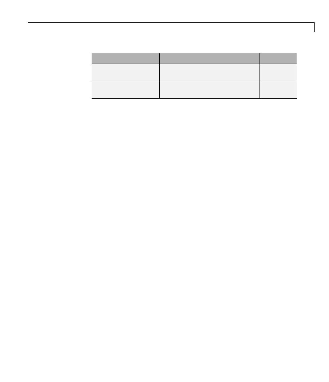
The data type of the image values determines which values correspond to
black and white as well as the absence or saturation of color. The following
table summarizes the interpretation of the upper and lower bound of each
data type. To view the data types of the signals at each port, from the Format
menu, point to Port/Signal Displays,andselectPort Data Types.
Page 27
Key Blockset Concepts
Black or Absence of
Data Type
Fixed point Minimum data type
Floating point
Note The V ideo and Image Processing Blockset software considers any data
type other than double-precision floating point and single-precision floating
pointtobefixedpoint.
For e xample, for an intensity image whose image values are 8-bit unsigned
integers, 0 is black and 255 is white. For an intensity im a ge whose image
values are double-precision floating point, 0 is black and 1 is white. For an
intensity image whose image values are 16-bit signed integers, -32768 is
black and 32767 is white.
For an RGB image whose image values are 8-bit unsigned integers, 0 0 0
is black, 255 255 255 is white, 255 0 0 is red, 0 255 0 is green, and 0 0 255
is blue. For an RGB image whose image values are double-precision
floating point, 0 0 0 is black, 1 1 1 is white, 1 0 0 is red, 0 1 0 is green,
and 0 0 1 is blue. For an RGB image whose image values are 16-bit
signed integers, -32768 -32768 -32768 is black, 32767 32767 32767 is
white, 32767 -32768 -32768 is red, -32768 32767 -32768 is green, and
-32768 -32768 32767 is blue.
Color
value
0
White or Saturation
of Color
Maximum data type
value
1
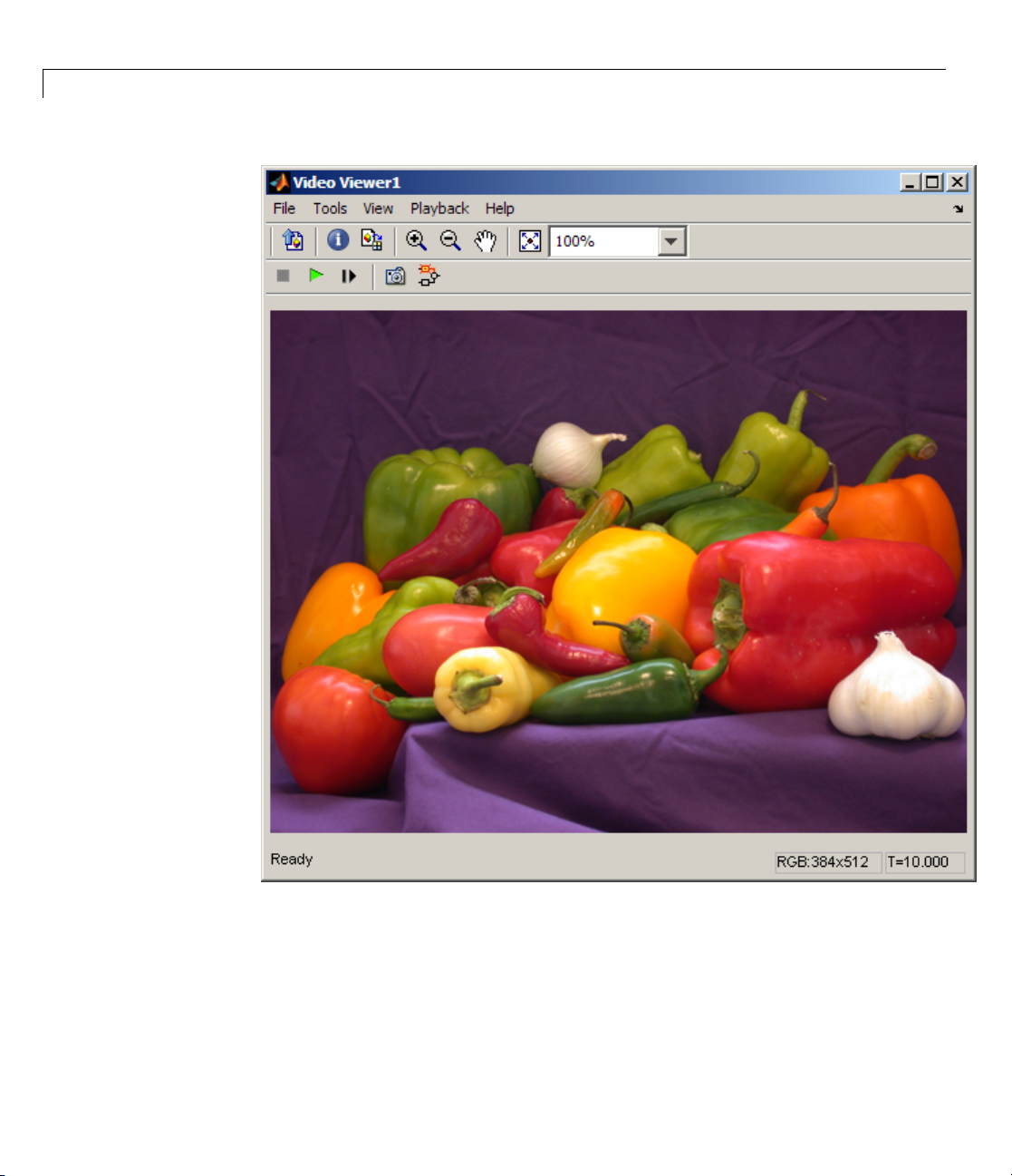
Color Image Processing
The Video and Image Processing Blockset software enables you to work with
color images and video signals as multidimensional arrays. For example,
the following model passes a color image from a source block to a sink block
using a 384-by-512-by-3 array.
1-17
Page 28

1 Getting Started
1-18
Page 29

Key Blockset Concepts
You can choose to process the image as a multidimensional array by setting
the Image signal parameter to
One multidimensional signal in the Image
From File block dialog box.
1-19
Page 30

1 Getting Started
The blocks that support multidimensional arrays meet at least one of the
following criteria:
1-20
• They have the Im age signal parameter on their block mask.
• They have a note in their block reference pages that says, “This block
supports intensity and color images on its ports.”
• Their input and output ports are labeled “Image”.
You can also choose to work with the individual color planes of images or
video s ig nals. For example, the following model passes a color image from a
source block to a sink block using three separate color planes.
Page 31

Key Blockset Concepts
1-21
Page 32
1 Getting Started
1-22
To process the individual color planes of an image or video signal, set the
Image signal parameter to
From File and Video Viewer block dialog boxes.
Separate color signals in both the Image
Page 33

Key Blockset Concepts
Note The ability to output separate color sign al s is a legacy option. It is
recommend that you use multidimensional signals to represent color data.
If you are working with a block that only outputs multidime n sional arrays,
you can use the Selector block to separate the color p la n es. For an example of
this process, see “Measuring an Ang le Between Lines” on page 4-18. If you are
1-23
Page 34

1 Getting Started
working with a block that only accepts multidimensional arrays, you can use
the Matrix Concatenation block to create a multidimensional array. For an
example of this process, see “Finding the Histogram of an Image” on page 4-73.
Coordinate Systems
You can specify locations in images using various coordinate systems. This
topic discusses pixel coordinates and spatial coordinates, wh ich are the two
main coordinate systems used in the Video and Image Processing Blockset
software.
Pixel Coordinates
Pixel coordinates enable you to specify locations in images. In this coordinate
system, the image is treated as a grid of discrete elements, ordered from top
to bottom and left to right, as shown in the following figure:
0
0
1
2
r
1
2
c
For pixel coordinates, the first component r (the row) increases downward,
while the second component c (the column) increases to the right. Pixel
coordinates are integer values and range from 0 to the length of the row or
1-24
Page 35

Key Blockset Concepts
column. The pixel coordin ates used in Video and Image Processing Blockset
software are zero based, while the pixel coordinates used by Image Processing
Toolbox and MATLAB are one based. For more information on the pixel
coordinate system used by Image Processing Toolbox, see “Pixel Coordinates”
in the Image Processing Toolbox documentation.
Spatial Coordinates
Spatial coordinates enable you to specify a location in an image with greater
granularity than pixel coordinates. For example, in the pixel coordinate
system, a pixel is treated as a discrete unit, uniquely identified by an integer
row and column pair, such as (3,4). In a spatial coordinate system , locations
in an image can be represented in terms of partial pixels, such as (3.3, 4.7).
The following figure illustrates the spatial coordinate system used for images:
0.5
-0.5
0
-0.5
0
1.5
1
2.5
2
c
0.5
1
1.5
2
2.5
r
This spatial coordinate system corresponds to the pixel co ordinate system
in the following ways. First, both are defined in terms of row and column
positions. Second, the spatial coordinates of the center point of any pixel are
identicaltothepixelcoordinatesforthat pixel. However, the pixel coordinate
system is discrete, while the spatial coordinate system is continuous. This
1-25
Page 36

1 Getting Started
means that, in pixel coordinates, the upper-left corner of an image is (0,0),
while in spatial coordinates, this location is (-0.5, -0.5). The spatial coordinate
system used by the Video and Image Processing Blockset software differs
from the one used by Image Processing Toolbox. For more information on this
spatial coordinate system, see “Spatial Coordinates” in the Image Processing
Toolbox documentation.
Image Data Stored in Column-Major Format
The MATLAB technical computing software and Video and Image Processing
Blockset blocks use column-major data organization. The blocks’ data buffers
store data elements from the first column first, then data elements from the
second column second, and so on through the last column.
If you have imported an image or a video stream into the MATLAB workspace
using a function from the MATLAB environment or the Image Processing
Toolbox, the Video and Image Processing Blockset blocks will display this
image or video stream correctly. If you have written y our own function or
code to import images into the MATLAB environment, you must take the
column-major convention into account.
1-26
Sample Time
Because the Video and Image Processing blocks calculate values directly
rather than solving differential equations, you must configure the Simulink
Solver to behave like a scheduler that uses each block’s sample time to
determine w hen the code behind the block is executed. The following steps
show you how to do this:
1 From the model’s Simulation menu, select Configuration Parameters.
The Configuration dialog box opens.
2 From the Type list, choose Fixed-step.
3 From the Solver list, choose Discrete (no continuous states).
The following figure shows the correctly configured Configuration dialog
box.
Page 37

Key Blockset Concepts
The S olve r, while in scheduler m ode, uses a block’s sam ple time to determine
when the code behind each block is executed. For example, if the sample
time of a Video From Workspace block is
0.05, the Solver executes the code
behind this block, and every other block with this sample time, once every
0.05 second.
Video Duration and Simulation Time
The duration of the simulation is controlled by the Stop time parameter —
not the input video. If you want the simulation to run for the duration of the
input video, you must adjust the Stop time parameter. If your video is being
cropped, increase the parameter value. If your video is complete and the
display window is black, decrease the parameter value. To view the first N
frames of your video, set the Stop time parameter to (N-1)*T
thesampletimeofyoursourceblock.
You can access the Stop time parameter in the model window, as shown in
the following figure, or on the Solver pane of the Configuration dialog box.
,whereTsis
s
1-27
Page 38

1 Getting Started
1-28
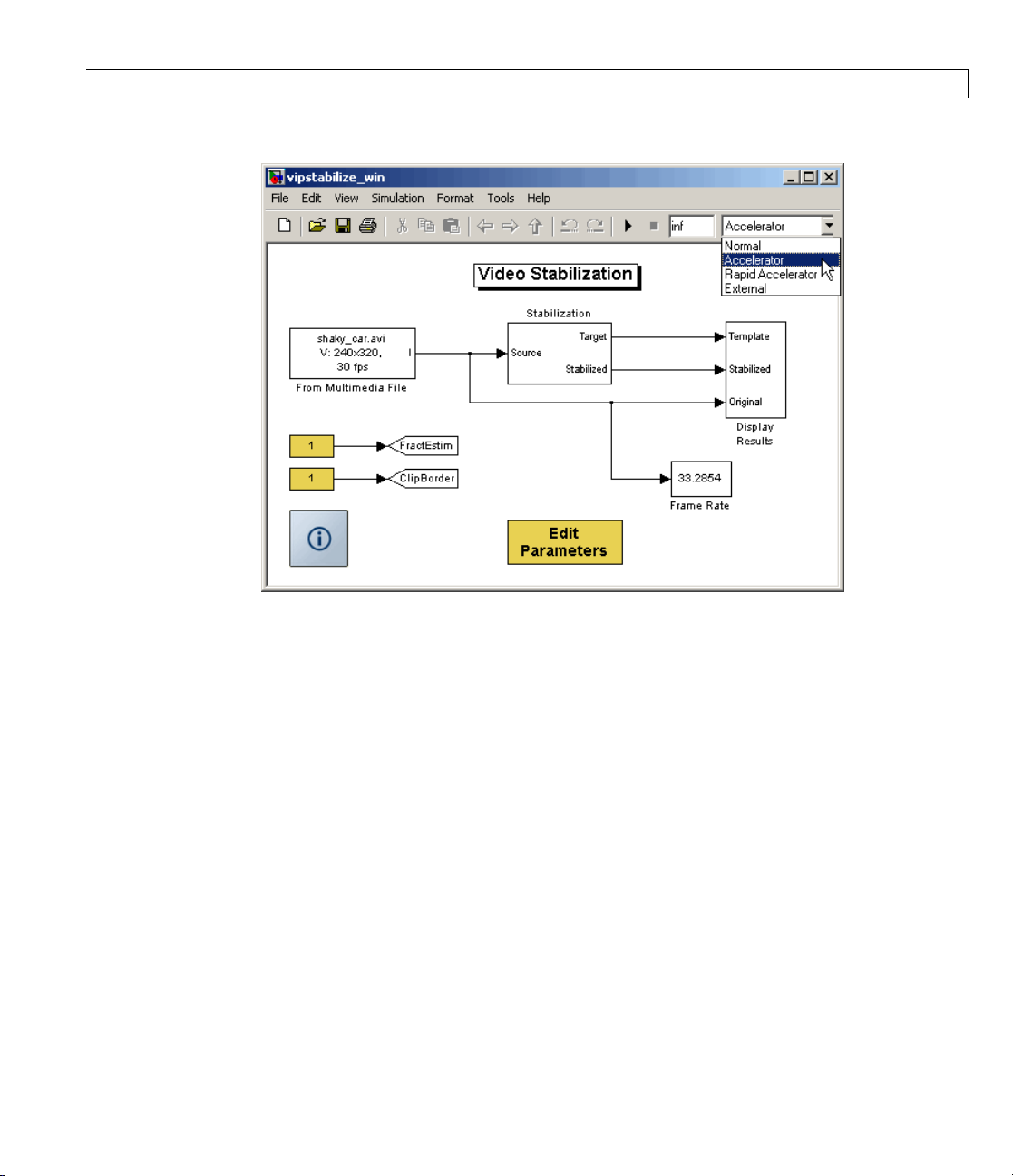
Acceleration Modes
The Simulink softwa r e offer Accelerator and Rapid Accelerator
simulation modes that remove much of the computational overhead required
by Simulink models. These modes compile target code of your model. Through
this method, the Simulink environment can achieve substantial performance
improvements for larger models. The performance gains are tied to the size
and complexity of your model. Therefore, large models that contain Video
and Image Processing Blockset blocks run faster in
Accelerator mode.
To change between
the drop-down list at the top of the model window.
Rapid Accelerator, Acc ele rator,andNormal mode, use
Rapid Accelerator or
Page 39
Key Blockset Concepts
For m ore information on the accelerator modes in Simulink, see “Accelerating
Models” in the Simulink User’s Guide.
Strategies for Real-Time Video Processing
Video processing is computationally intensive, and the ability to perform
real-time video processing is affected by the following facto rs:
• Hardware capability
• Model complexity
• Model implementation
• Input data size
Optimizing Your Implementation
Optimizing your implementation is a crucial step toward real-time video
processing. The following tips can help improve the performance of y our
model:
1-29
Page 40

1 Getting Started
• Minimize the number of blocks in your model.
• Process only the regions of interest to reduce the input data size.
• Use efficient algorithms or the simplest version of an algorithm that
achieves the desired result.
• Use efficient block parameter settings. However, you need to decide
whether these settings best suit your algorithm. For example, the most
efficient block parameter settings m ight not yield the most accurate results.
You can find out more about individual block parameters and their effect
on performance by reviewing specific block reference pages.
The tw o following examples show settings that make each block’s operatio n
the least computationally expensive:
- Resize block — Interpolation method = Nearest neighb or
- Blocks that support fixed point — On the Fixed-Point tab, Overflow
mode =
• Choose data types carefully.
Wrap
1-30
- Avoid data type conversions.
- Use the smallest data type necessary to represent your data to reduce
memory usage and accelerate data processing.
In simulation mode, model s with floating-point data types run faster
than models with fixed-point data types. To speed up fixed-point models,
you must run them in accelerator mode. Simulink contains additional
code to process all fixed-point data types. T his code affects simulation
performance. After you run your model in accelerator mode or g enerate
codeforyourtargetusingReal-Time Workshop, the fixed-point data
types are specific to the choices you made for the fixed-point parameters.
Therefore, the fixed-point model and generated code run faster.
Developing Your Models
Use the following general process guidelines to develop real-time video
processing models to run on embedded targets. By optimizing the model at
each step, you improve its final performance.
Page 41

Key Blockset Concepts
1 Create the initial model and optimize the implementation algorithm. Use
floating-point data types so that the model runs faster in simulation mode.
If yo u are working with a floating-point processor, go to step 3.
2 If you are working with a fixed-point processor, gradually change the model
data types to fixed point, and run the model after every modification.
During this process, you can use data type conversion blocks to isolate
the floating point sections of the model from the fixed-point sections. You
should see a performance improvement if you run the model in accelerator
mode.
3 Remove unnecessary sink blocks, including scopes, and blocks that log
data to files.
4 Compile the model for deployment on the embedded target.
Code Generation
The Video and Image Processing Blo cks et, Real-Time Workshop®,and
Real-Time Workshop
code that you can use to implement your model for a practical application. For
instance, you can create an executable from your Simulink model to run on a
target chip. For more information, see“UnderstandingCodeGeneration”in
Signal Processing Blockset Getting Started Guide..
®
Embedded Coder™ software enable you to generate
Shared Library Dependencies
For the blocks listed in the table be low, copy the shared library files from the
machine where the blockset software is installed to a folder on the system
path of the destination machine.
1-31
Page 42

1 Getting Started
Block Dependent library
file
To Multimedia File
From Multimedia File
To Video Display tovideodevice.dll
tommfile.dll
SldirectShow.dll
frommmfile.dll
SldirectShow.dll
SldirectShow.dll
Product
Signal Processing
Blockset™
Signal Processing
Blockset
Video and Image
Processing Blockset
1-32
Page 43
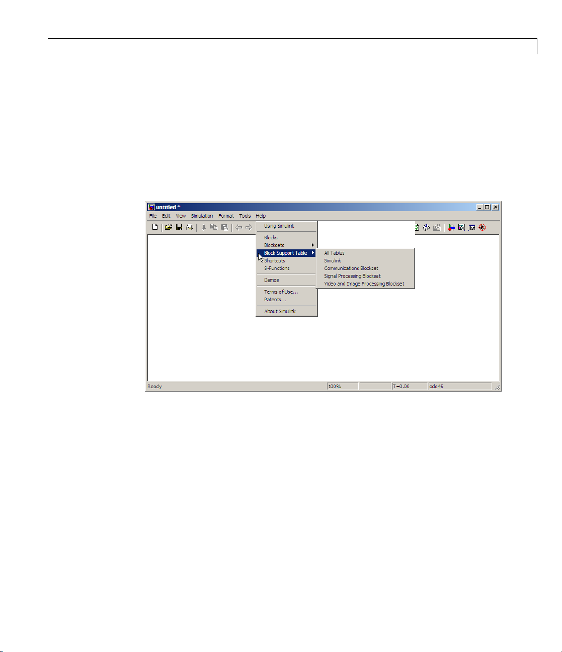
Block Data Type Support
The Video and Image Processing Blockse t Data Type Support Table is
now available through the Simulink model Help menu. The table provides
information about data type support and code generation coverage for all
Video and Image Processing Blockset blocks. Select Help > Block Su pport
Table> Video and Image Processing Blockset or Help > Block Support
Table > All T ables.
Block Data Type Support
You can also type showvipblockdatatypetable at the MATLAB command
line to bring up the table.
1-33
Page 44

1 Getting Started
Image Credits
ThistableliststhecopyrightownersoftheimagesusedintheVideoand
Image Processing Blockset documentation.
Image Source
cameraman
cell
circuit
moon
Copyright Massachusetts Institute of
Technology. Used with permission.
Cancer cell from a rat’s prostate,
courtesy of Alan W. Partin, M.D.,
Ph.D., Johns Hopkins University
School of Medicine.
Micrograph of 16-bit A/D converter
circuit, courtesy of Steve Decker and
Shujaat Nadeem, MIT, 1993.
Copyright Michael Myers. Used with
permission.
1-34
Page 45

Importing and Exporting
Images and Video
• “Batch Processing Image Files” on page 2 -2
• “Working with Live Video” on page 2-7
• “Working with Multimedia Files” on page 2-8
• “Working with M ATLA B Workspace Variables” on page 2-43
2
Page 46

2 Importing and Exporting Images and Video
Batch Processing Im age Files
A common image processing task is to apply an image processing algorithm
to a series of files. In this example, you import a sequence of images from a
folder into the MATLAB workspace and display the sequence using the Video
and Image Processing Blockset software.
Note In this example, the image files are a set of 10 microsco pe images of rat
prostate cancer cells. These files are only the first 10 of 100 images acquired.
1 Specify the folder containing the images, and use this information to create
a list o f the file names, as follows:
fileFolder = fullfile(matlabroot,'toolbox', ...
'images','imdemos');
dirOutput = dir(fullfile(fileFolder,'AT3_1m4_*.tif'));
fileNames = {dirOutput.name}'
2-2
2 View one of the images, using the following command sequence:
I = imread(fileNames{1});
imshow(I);
text(size(I,2),size(I,1)+15, ...
'Image files courtesy of Alan Partin', ...
'FontSize',7,'HorizontalAlignment','right');
text(size(I,2),size(I,1)+25, ....
'Johns Hopkins University', ...
'FontSize',7,'HorizontalAlignment','right');
Page 47

Batch Processing Image Files
3 Useaforlooptocreateavariablethatstorestheentireimagesequence.
YouaregoingtousethisvariabletoimportthesequenceintoSimulink.
for i = 1:length(fileName s)
my_video(:,:,i) = imread(fileNames{i});
end
4 Create a new Simulink model, and add to it the blocks shown in the
following table.
2-3
Page 48
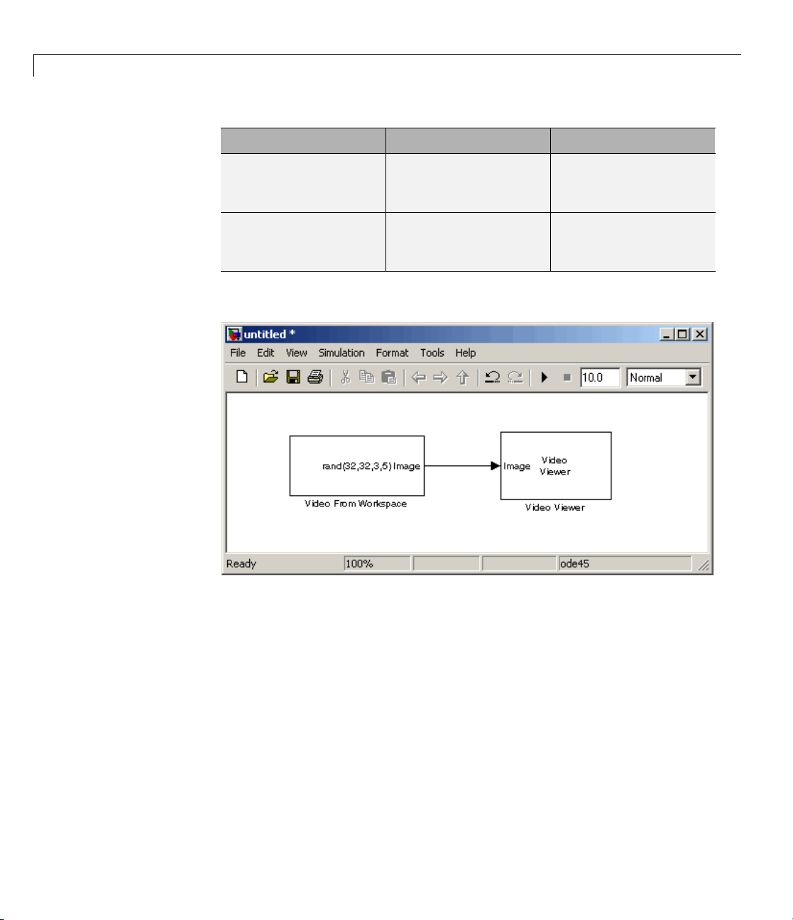
2 Importing and Exporting Images and Video
Block Lib rary Quantity
Video From Workspace Video and Image
Video Viewer Video and Image
5 Connect the blocks so your model looks similar to the following figure.
1
Processing Blockset >
Sources
1
Processing Blockset >
Sinks
2-4
6 Use the Video From Workspace block to import the image sequence into
Simulink. Set the Signal parameter to
7 Use the Video Viewer block to view the image sequence. Accept the default
my_video.
parameters.
the configuration parameters. Open the Configuration dialog box by
8 Set
ecting Simulation > Configuration Parameters.OntheSolver
sel
e, set the parameters as follows:
pan
• St
• Ty
op time =
pe =
10
Fixed-step
Page 49

Batch Processing Image Files
• Solver = Discrete (no continuous states)
Because the Video From Workspace block’s Sample time parameter is s et
to
1 and the Stop time parameter is set to 10,theVideoViewerblock
displays 10 images before the simulation stops.
9 Run your model. You can view the image sequence in the Video Viewer
window.
2-5
Page 50

2 Importing and Exporting Images and Video
For more information on the blocks used in this example, see the Video
FromWorkspaceandVideoViewerblock reference pages. For additional
information about batch processing, see the Batch Processing Image Files
Using Distributed Computing demo in Image Processing Toolbox. You can
run this demo by typing
ipexbatch at the MATLAB command prompt.
2-6
Page 51

Working with Live Video
Image Acquisition Toolbox provides functionsforacquiringimagesandvideo
directly into MATLAB and S im ulink from PC-compatible imaging hardware.
You can detect hardware automatically, configure hardware properties,
preview an acquisition, and acquire images and video.
SeethelivevideoprocessingdemostoviewdemosthatusetheImage
Acquisition Toolbox together with Video and Image Processing blocks. To
see the full list of Video and Im a ge Processing demos, type
MATLAB command prompt.
Working with Live Video
vipdemos at the
2-7
Page 52

2 Importing and Exporting Images and Video
WorkingwithMultimediaFiles
In this section...
“Blocks That Suppo rt Multimedia Files” on page 2-8
“Importing and Viewing Multim edia Files” on page 2-8
“Exporting to Multimedia Files” on page 2-11
“Working with AVI Files” on page 2-14
“Working with Audio” on page 2-38
Blocks That Support Multimedia Files
The Video and Image Processing Blockset software contain blocks that you
can use to import and export multimedia files. These blocks include the From
Multimedia File block and the To Multimedia File block. If you are working
on a Windows platform, these blocks perform best on platforms with DirectX
Version 9.0 or later and Windows Media Player Version 11 or later. These
blocks also support code generation.
2-8
Importing and Viewing Multimedia Files
In this example, you use the From M ul timedia File block to import a video
stream into a Simulink model and th e To Video Display block to view it. This
procedure assumes you are working on a Windows platform:
1 Create a new Simulink model, and add to it the blocks shown in the
following table.
Block Lib rary Quantity
From Multimedia File Video and Image
Processing Blockset >
Sources
Video Display
To
deo and Image
Vi
rocessing Blockset >
P
inks
S
1
1
Page 53

Working with Multimedia Files
2 Locate a multimedia file that you want to import into Simulink. If you
do not have access to a multimedia file, the Video and Image Proces sing
Blockset software has sample multimedia files you can use to complete
this procedure.
3 Use the From Multimedia File block to import the multimedia file into the
model. Double-click the From Multimedia File block:
• If you do not have your own multimedia file, enter
vipmen.avi for the
File name param eter.
• If the multimedia file is on your MATLAB path, enter the filename for
the File name parameter.
• IfthefileisnotonyourMATLABpath,usetheBrowse button to locate
the multimedia file.
• Set the Image signal parameter to
By default, the Numberoftimestoplayfileparameter is set to
Separate color signals.
inf.The
model continues to play the file until the simulation stops.
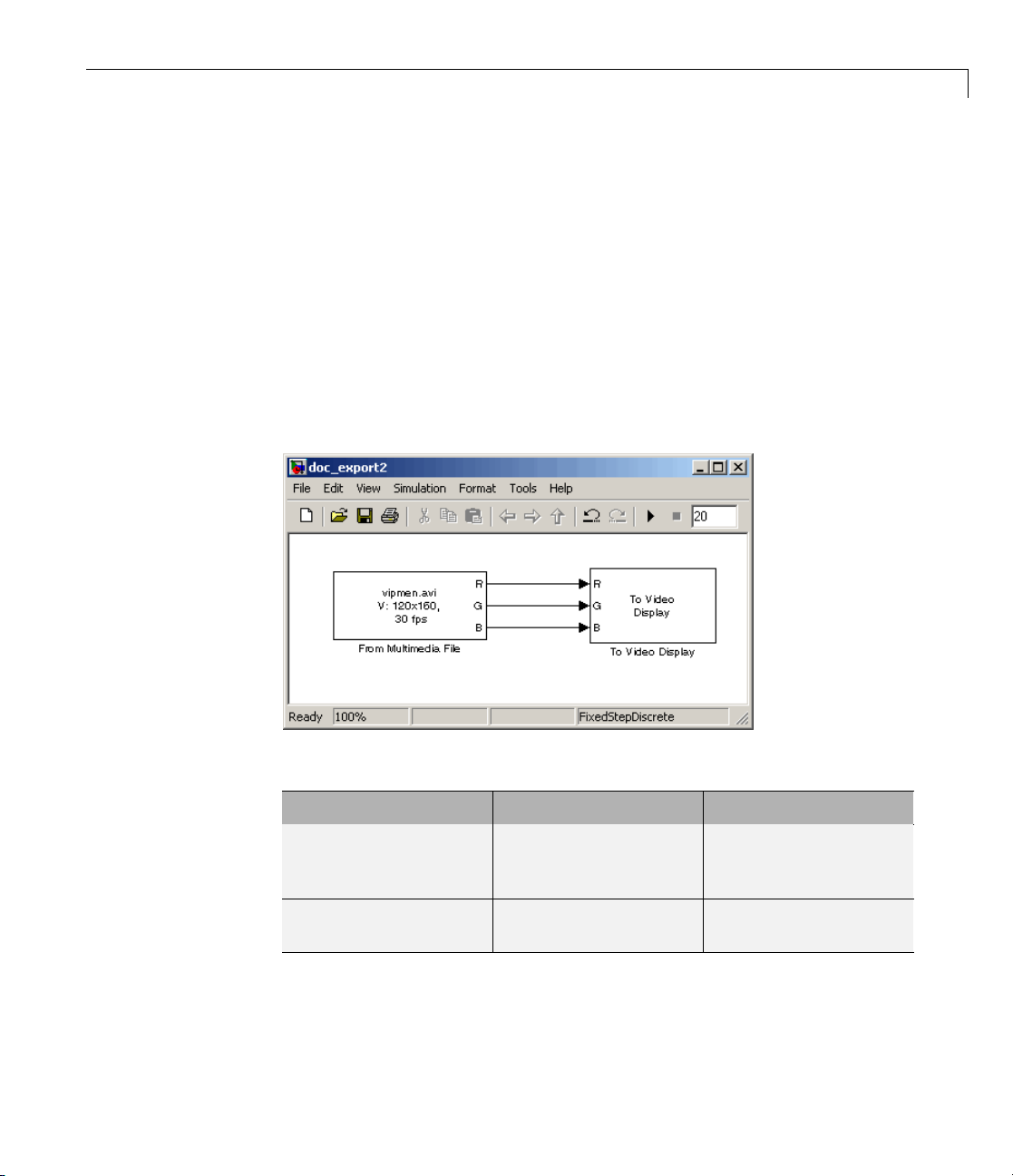
4 Use the To Video Display block to view the multimedia file. Set the Image
signal parameter to
5 Connect the blocks so your model looks similar to the following figure.
Separate color signals.
2-9
Page 54

2 Importing and Exporting Images and Video
6 Set the configuration parameters. Open the Configuration dialog box by
selecting Configuration P arameters from the Simulation menu. On
the Solver pane, set the parameters as follows:
• Stop time =
• Type = Fixed-step
• Solver = Discrete (no continuous states)
7 Run your model.
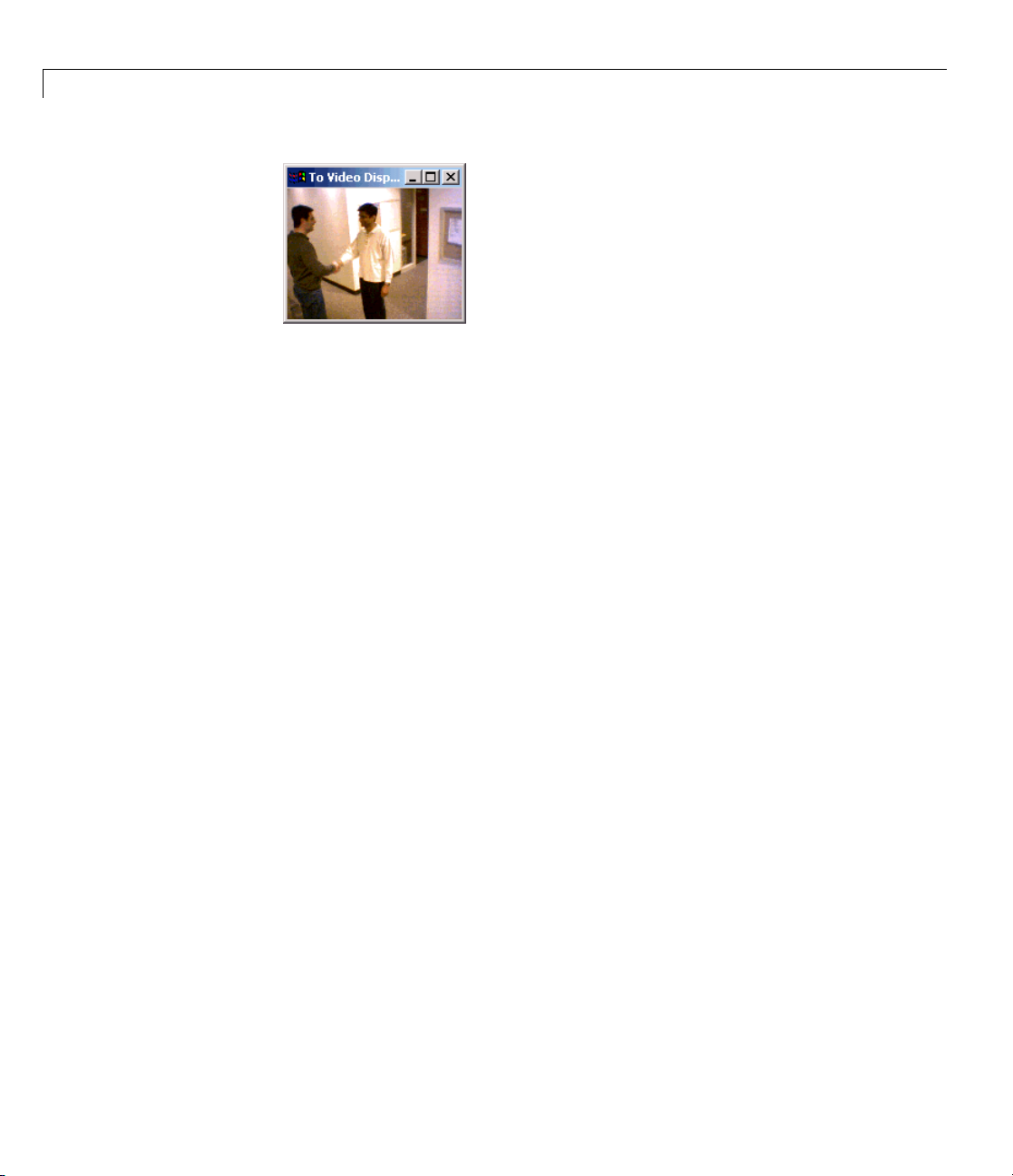
View your video in the To Video Display window that automatically
appears when you start your simulation. This window closes as soon as
the simulation stops.
Note The video that is disp la yed in the To Video Display window runs at
the frame rate that corresponds to the input sample time. To run the video
as fast as Simulink processes the video frames, use the Video V iewer block.
20
2-10
You have now imported and displayed a multimedia file in your Simulink
model. In “Exporting to Multimedia Files” on page 2-11, you manipulate your
video stream and export it to a multimedia file. For more information on the
blocks used in this example, see the From Multimedia File and To Video
Display block reference pages in the Video and Image Processing Blockset
Reference. To listen to audio associated with an AVI file, use the To Audio
Device block in Signal P rocessing Blockset software.
Page 55
Working with Multimedia Files
Exporting to Mul
The Video and Ima
data from your Si
File block to ex
1 If the model yo
page 2-8 is not o
by typing
doc_export2
at the MATLA
ge Processing Blockset blocks enable you to export video
mulink model. In this section, you use the To M ultimedia
port an multimedia file from your model.
u created in “Importing a n d Viewing Multimedia Files” on
penonyourdesktop,youcanopenanequivalentmodel
Bcommandprompt.
timedia Files
2 Click-and-drag the following blocks into your model.
Block Lib rary Quantity
To M ultimedia File Video and Image
Processing Blockset >
Sinks
Gain Simulink > Math
Operations
3 Use the Gain blocks to increase the red, green, and blue values of the video
stream. This increases the contrast of the video. Set the block parameters
as follows:
1
3
2-11
Page 56

2 Importing and Exporting Images and Video
• Main pane, Gain = 1.2
• Signal Attributes pane, Outpu t data type = Inherit: Same as
input
4 Use the To Multimedia File b lock to export the video to a multimedia file.
Set the block parameters as follows:
• Output file name =
• Write = Video only
• Image signal = Separate color signals
5 Connect the blocks as shown in the following figure. You might need to
resize some blocks to do so.
my_output.avi
2-12
Page 57

Working with Multimedia Files
You are now ready to set your block parameters by double-clicking the
blocks, modifying the block parameter values, and clicking OK.
6 If you have not already done so, set the configuration parameters. Open the
Configuration dialog box by selecting Configuration Parameters from
the Simulation menu. On the Solver pane, set the parameters as follows:
• Stop time =
20
• Type = Fixed-step
• Solver = Discrete (no continuous states)
7 Run your model.
You can view your video in the To Video Display window. By increasing the
red, green, and blue color values, you increased the contrast of the video.
TheToMultimediaFileblockexportsthevideodatafromtheSimulink
model to a multimedia file that it creates in your current folder.
2-13
Page 58
2 Importing and Exporting Images and Video
You have now manipulated your video streamandexporteditfromaSimulink
model to a multimedia file. For more information, see the To Multimedia File
block reference page in the Video and Image Processing Blockset Reference.
Working with AVI Files
• “Importing and Viewing AVI Files” on page 2-14
• “Exporting to AVI Files” on page 2-18
• “Annotating AVI Files with Video Frame Numbers” on page 2-22
2-14
• “Annotating AVI Files at Two Separate Locations” on page 2-26
• “Saving Portions of an AVI File to Separate Files” on page 2-30
Importing and Viewing AVI Files
Before you can analyze or operate on your data, you must import it into
your Simulink model. Blocks from the Sources library, such as the From
Multimedia File block, can help you with this type of task.
In this section, you use the From Multimedia File block to import video from
an AVI file into your model a n d the Video Viewer block to view it:
1 Create a new Simulink model, and add to it the blocks shown in the
following table.
Page 59
Working with Multimedia Files
Block Library Quantity
From Multimedia File Video and Image Processing
1
Blockset > Sources
Video Viewer Video and Image Processing
1
Blockset > Sinks
2 Use the From Multimedia File block to import an AVI file into the model.
Double-click the From MultimediaFileblock. TheVideoandImage
Processing Blockset software has sample AVI files you can use to complete
this procedure.
• If you do not have your own AVI file, enter
barcodes.avi for the File
name parameter.
• If the AVI file is on your MATLAB path, enter the AVI filename for
the File name parameter.
• IfthefileisnotonyourMATLABpath,usetheBrowse button to locate
the AVI filename.
• Image signal =
Separate color signals
By default, the Numberoftimestoplayfileparameter is set to inf.The
model continues to play the file until the simulation stops.
3 Use the Video Viewer block to view the AVI file. Click the File menu of
the Video Viewer GUI to set the Image signal param eter to
color signals
4 Connect the blocks so your model looks similar to the following figure.
.
Separate
2-15
Page 60

2 Importing and Exporting Images and Video
5 Set the con
selecting
as follows
• Solver pa
• Solver pa
• Solver p
6 Run your model.
figuration parameters. Open the Configuration dialog box by
Simulation > Configuration Parameters. Set the parameters
:
ne, Stop time =
ne, Type =
ane, Solver =
20
Fixed-step
Discrete (no continuous s tates)
View your video in the Video Viewer window that automatically appears
when you start your simulation.
2-16
Page 61

Working with Multimedia Files
Note Th
as Sim
and yo
input
You h
orting to AVI Files” on page 2-18, you manipulate your video stream
“Exp
export it to an AVI file. For more information on the blocks used in this
and
mple, see the From Multimedia File and Video Viewer block reference
exa
es in the Video and Image Processing Blockset Reference.Tolistento
pag
e video that is displayed in the Video Viewer window runs as fast
ulink processes the video frames. If you are on a Windows platform
u want to run the video at the frame rate that corresponds to the
sample time, use the To Video Display block.
ave now imported and displayed video data in you r Simulink model. In
2-17
Page 62
2 Importing and Exporting Images and Video
audioassociatedwithanAVIfile,usetheToAudioDeviceblockinSignal
Processing Blockset software.
Note The Video Viewer block is supported on all platforms, but it does not
support code generation. If you are onaWindowsplatform,youcanuse
the To Video Display block to display video data. This block supports code
generation. For more information, see the To Video Display block reference
page in the Video and Image Processing Blockset Reference.
Exporting to AVI Files
The Video and Image Processing Blockset blocks enables you to export video
data from your Simulink model. In the following procedure, you use the To
Multimedia File block to export video data from your m odel into an AVI file:
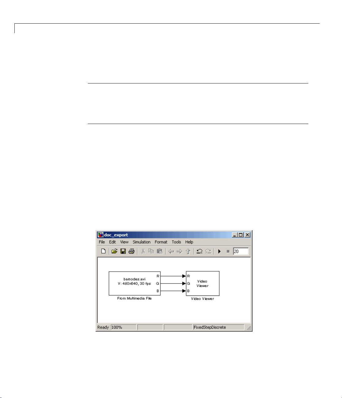
1 If the model you created in “Importing and Viewing AVI Files” on page 2-14
is not open on your desktop, open an equivalent model by typing
2-18
doc_export
at the MATLAB command prompt.
2 Click-and-dragtheblocksshownonthefollowingtableintoyourmodel.
Page 63

Working with Multimedia Files
Block Lib rary Quantity
To M ultimedia File Video and Image Processing
1
Blockset > Sinks
Gain Simulink > Math Operatio ns
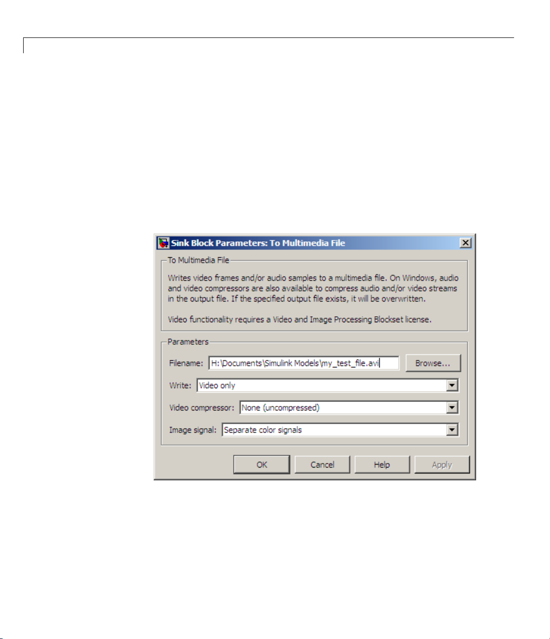
3 Change the inputs to the To Multimedia File block. Set the block
2
parameters as follows:
• Write =
Video only
• Image signal = Separate color signals
4 Connect the blocks as shown in the following figure. You might need to
resize some blocks to do so.
e the Gain block to change the green values of the video stream. Set the
5 Us
ock parameters as follows:
bl
2-19
Page 64
2 Importing and Exporting Images and Video
• Main pane, Gain = 0.3
• Signal Attributes pane, Output data type = Inherit:Same a s input
6 Use the Gain1 block to change the blue values of the video stream. Set the
block parameters as follows:
• Main pane, Gain =
1.5
• Signal Attributes pane, Output data type = Inherit:Same a s input
7 Use the To Multimedia File block to export the video to an AVI file. Set
the File name parameter to
my_test_file.avi.
2-20
8 If you have not already done so, set the configuration parameters. Open
the Configuration dialog box by selecting Simulation > Configuration
Parameters. Se t the parameters as follows:
• Solver pane, Stop time =
20
• Solver pane, Type = Fixed-step
Page 65

Working with Multimedia Files
• Solver pane, Solver = Discrete (no continuous s tates)
9 Run your model.
You can view your video in the Video Viewer window. The To Multimedia
File block exports the video data from the Simulink model to an AVI file
that it creates in your current folder.
You have now manipulated your video streamandexporteditfromaSimulink
model to an AVI file. For more information , see the To Multimedia File block
reference page in the Video and Image Processing Blockset R eference.
2-21
Page 66
2 Importing and Exporting Images and Video
Annotating AVI Files with Video Frame Numbers
You can use the Insert Text block to overlay text on video stream. In this
example, you add a running count of the number of video frames to a video.
1 Create a new Simulink model, and add to it the blocks shown in the
following table.
Block Lib rary Quantity
From Multimedia File Video and Image Processing
Insert Text
Video Viewer Video and Image Processing
2 Position the blocks as shown in the f ollowing figure.
Blockset > Sources
VideoandImageProcessing
Blockset > Text & Graphics
Blockset > Sinks
1
1
2
2-22
3 Use the From Multimedia File block to import the video into the Simulink
model. Set the Image color space parameter to
Intensity.
Page 67

Working with Multimedia Files
4 Open the Surveillance Recording demo by typing
vipsurveillance
at the MATLAB command prompt.
5 Click-and-drag the Frame Counter block from the demo model into your
model. This block counts the number of frames in an input video.
6 Use the Insert Text block to annotate the video stream with a running
framecount. Settheblockparameters as follows:
• Main pane, Text =
%d']
['Frame count' sprintf('\n') 'Source frame:
• Main pane, Location = [85 2]
• Main pane, Color value = 1
• Font pane, Font face = LucindaTypewriterRegular
By setting the Text parameter to ['Frame count' sprintf('\n')
'Source frame: %d']
one line and the
Source frame: on a new line. Because you specified %d,
, you are asking the block to print Frame count on
an ANSI C printf-style format s pecification, the Variables port appears on
the block. The block takes the port input (it is expecting a decimal) and
substitutes it for the
%d in the string. You used the Location parameter to
specify where to print the text. In this case, the location is 85 rows down
and 2 columns over from the top left corner of the image.
7 UsetheVideoViewerblockstoviewthe original and annotated videos.
Accept the default parameters.
8 Connect the blocks as shown in the following figure.
2-23
Page 68

2 Importing and Exporting Images and Video
2-24
9 Set the configuration parameters. Open the Configuration dialog box by
selecting Configuration Parameter s from the Sim ulation menu. Set
the parameters as follows:
• Solver pane, Stop time =
• Solver pane, Type = Fixed-step
• Solver pane, Solver = Discrete (no continuous s tates)
10 Run the model.
The original video appears in the Video Viewer window.
inf
Page 69

Working with Multimedia Files
The annotated video appears intheVideoViewer1window.
2-25
Page 70

2 Importing and Exporting Images and Video
You have now added descriptive text to a video stream. For more information,
see the Insert Text block reference page in the Video and Image Processing
Blockset R eference. For related information, see the Draw Shapes and Draw
Markers block reference pages.
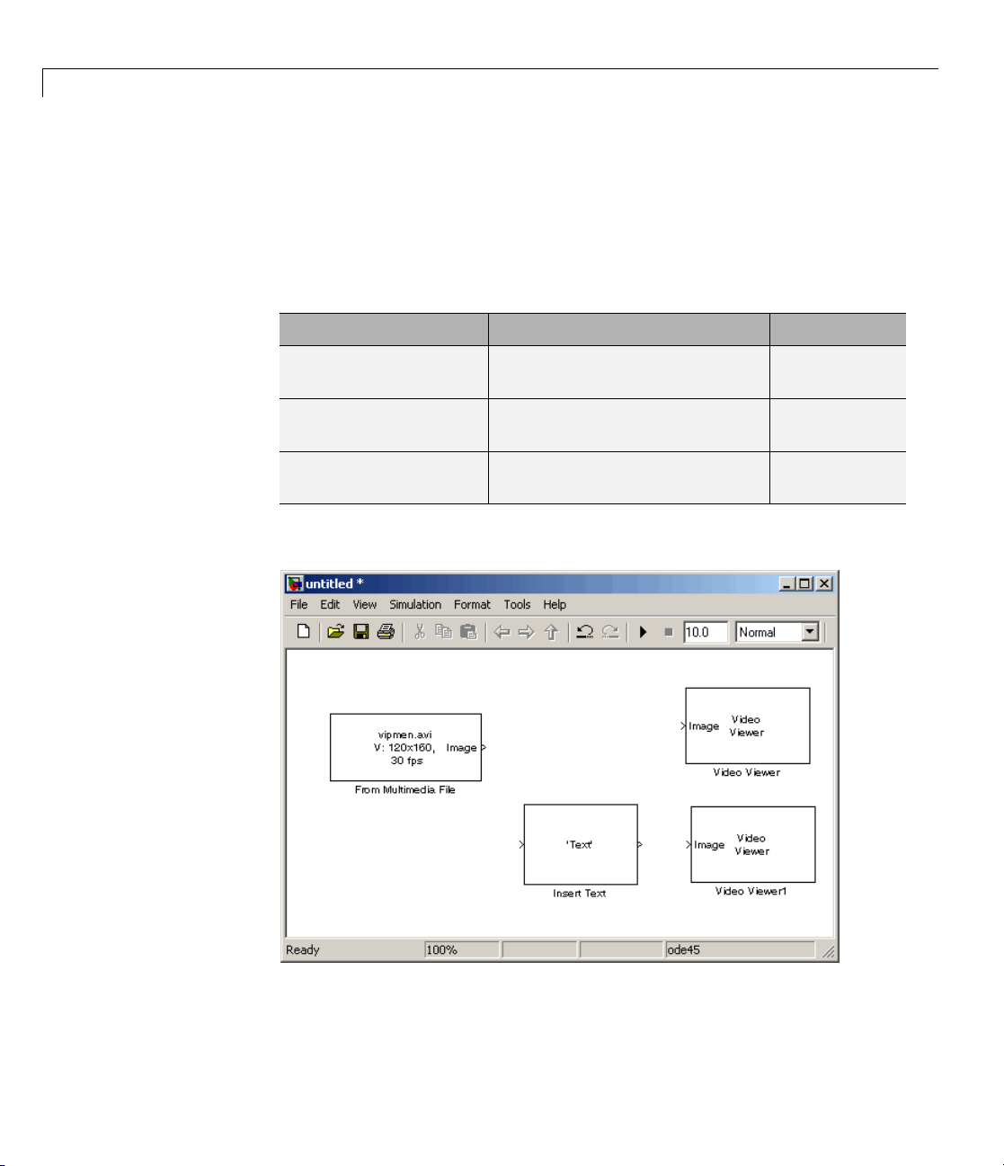
Annotating AVI Files at Two Separate Locations
You can use the Insert Text block to overlay text on a video stream at two
separate locations in the video frame.
1 Create a new Simulink model, and add to it the blocks shown in the
following table.
Block Lib rary Quantity
From Multimedia File Video and Image Processing
Insert Text
Video Viewer Video and Image Processing
Constant Simulink > Sources
Blockset > Sources
VideoandImageProcessing
Blockset > Text & Graphics
Blockset > Sinks
1
1
1
1
2-26
2 Position the blocks as shown in the f ollowing figure.
Page 71

Working with Multimedia Files
3 Use the From Multimedia File block toimportthevideostreamintothe
Simulink model. Accept the default parameters.
4 Use the Insert Text block to annotate the video with two text strings. Set
the block parameters as follows:
• Main pane, Text =
'Text position: Row %d and Column %d'
• Main pane, Location = [[5 10]' [80 10]']
By setting the Text parameter to 'Text position: Row %d and Column
, you are asking the block to replace each conversion specification
%d'
(%d) with a decimal input to the Variables port. You used the Location
parametertospecifywheretoprinteach text string. In this case, the block
places the top-left corner of the text box that surrounds the first text string
5 rows down and 10 rows over from the top left corner of the image. The
block places the second text string 80 rows down and 10 rows over.
5 Use the Constant block to specify the decimal values input into the Insert
Text b lock’s Variables port. Because the conversion specification is %d, the
values must be an integer data type. Set the block parameters as follows:
• Main pane, Constant value =
[[5 10]' [80 10]']
2-27
Page 72

2 Importing and Exporting Images and Video
• Main pane, clear the Interpret vector parameters as 1–D check box.
• Signal Attributes pane, Output data type =
uint8
The Insert Text block substitutes the values from the first column of the
Constant value parameter into the first text string a nd the values from
the second column into the second text string.
6 Use the Video Viewer blocks to view the annotated image. Accept the
default parameters.
7 Connect the blocks as shown in the following figure.
2-28
8 Set the configuration parameters. Open the Configuration dialog box by
selecting Configuration Parameter s from the Sim ulation menu. Set
the parameters as follows:
• Solver pane, Stop time =
inf
• Solver pane, Type = Fixed-step
• Solver pane, Solver = Discrete (no continuous s tates)
Page 73

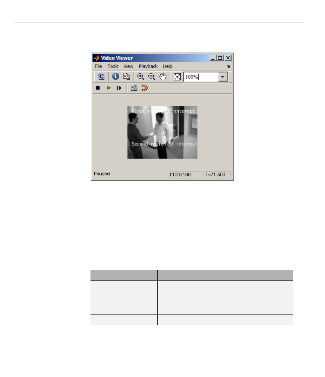
9 Run the model.
The annotated video appears in the Video Viewe r window.
Working with Multimedia Files
Alternatively, you can input two string values at the Variables port.
10 OntheInsertTextblockdialogbox,settheText parameter to'%s region
of interest'
.
You are asking the block to replace the %s conversion specification with a
string input to the Variables port.
11 Use the Constant block to specify the strings to substitute into the first
and second text strings. Because the conversion specification is %s, the
values must be 8-bit unsigned integer data types. Set the Constant value
parameter to
12 Run the model.
[uint8('First') 0 uint8('Second')].
The annotated video appears in the Video Viewe r window.
2-29
Page 74
2 Importing and Exporting Images and Video
2-30
You have n
see the In
Blockse
ow added descriptive text to a video stream. For more information,
sert Text block reference page in the Video and Image Processing
t Reference.
Saving Portions of an AVI File to Separate Files
In this
save po
1 Creat
section, you use To Multimedia File and Enabled Subsystem blocks to
rtionsofoneAVIfiletothreeseparateAVIfiles.
e a new Simulink model, and add to it the blocks shown in the
wing table.
follo
Block Library Quantity
Multimedia File
From
Insert Text
Enabled Subsystem Simulink > Ports & Subsystems
oandImageProcessing
Vide
kset > Sources
Bloc
VideoandImageProcessing
Blockset > Text & Graphics
1
1
3
Page 75

Working with Multimedia Files
Block Library Quantity
To Multimedia File Video and Image Processing
3
Blockset > Sinks
Counter Signal Processing Blockset >
1
Signal Management > Switches
and Counters
CompareToConstant Simulink > Logic and Bit
5
Operations
Logical O perator Simulink > Logic and Bit
1
Operations
Stop Simulation Simulink > Sinks
2 Place the blocks so that your model looks similar to the one in the following
1
figure.
2-31
Page 76

2 Importing and Exporting Images and Video
2-32
3 Use the From Multimedia File block to import an AVI file into your model.
Set the parameters as follows:
• Uncheck Inherit sample time from file checkbox
• Set Desired sample time parameter =
4 UsetheInsertTextblocktoannotatethevideostreamwiththeframe
numbers. Set the parameters as follows:
• Text =
• Location = [10 10]
• Color = [0 1 0]
'Frame %d'
1/30
Page 77

Working with Multimedia Files
The b lo ck writes the frame number in green in the upper-left corner of the
output video stream.
5 Double-click each Enabled Subsystem block, and click-and-drag one of the
To Multimedia File blocks into it.
6 Inside each Enabled Subsystem, connect the blocks so that your subsystem
looks similar to the one in the following figure.
7 Use th
sepa
• Outp
• Wri
eToMultimediaFileblockstosendthevideostreamtothree
rate AVI files. Set the block parameters as follows:
ut file name =
ectively
resp
te =
Video only
output1.avi, output2.avi,andoutput3.avi,
Each enabled subsystem should now look similar to the subsystem shown
in the following figure.
2-33
Page 78

2 Importing and Exporting Images and Video
2-34
8 Use the Counter block to count the number of video frames. You use this
information to specify which frames are sent to which file. Set the block
parameters as follows:
• Count event =
Free running
• Initial count = 1
• Output = Count
• Clear the Reset input check box.
• Sample time =
1/30
• Count data type = uin t16
9 Use t
heComparetoConstantblocktosendframes1to9tothefirstAVI
. Set the block parameters as follows:
file
• Ope
• Con
rator =
stant value =
<
10
Page 79

Working with Multimedia Files
10 UsetheComparetoConstant1andCompare to Constant2 blocks to send
frames 10 to 19 to the second AVI file. Set the Compare to Constant1 block
parameters as follows:
• Operator =
>=
• Constant value = 10
Set the Compare to Constant2 block parameters as follows:
• Operator =
<
• Constant value = 20
11 Use the Compare to Constant3 block to send frames 20 to 30 to the third
AVI file. Set the block parameters as follows:
• Operator =
>=
• Constant value = 20
12 Use the Compare to Constant4 block to stop the simulation when the video
reaches frame 30. Set the block parameters as follows:
• Operator =
==
• Constant value = 30
• Output data type mode = boolean
13 Connect the blocks so that your model resembles the one in the following
figure.
2-35
Page 80

2 Importing and Exporting Images and Video
2-36
14 Set the configuration parameters. Open the Configuration dialog box by
selecting Simulation > Configuration Parameters. Set the parameters
as follows:
• Solver pane, Type =
• Solver pane, Solver = Discrete (no continuous s tates)
15 Run your model.
The model saves the three output AVI files in your current folder.
Fixed-step
Page 81
Working with Multimedia Files
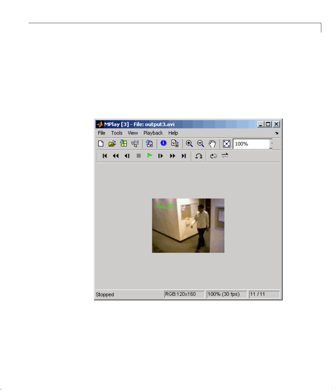
16 ViewtheresultingfilesbytypingthefollowingcommandsattheMATLAB
command prompt:
mplay output1.avi
mplay output2.avi
mplay output3.avi
Then, press the Play button on the MPlay G UI.
You have now sent portions of an AVI filetothreeseparateAVIfilesusing
an Enabled Subsystem block, a To Multimedia File block, and a trigger
signal. For more information on the blocks used in this example, see the
From Multimedia File, Insert Text, Enabled Su b system, and To Multimedia
File block reference pages.
2-37
Page 82

2 Importing and Exporting Images and Video
Working with Aud
In this example,
stream into a Sim
software From W
Then you write t
File block.
This procedur
1 Create a new S
following ta
Block Lib rary Quantity
From Multi
From Wave File
To M ultimedia File Video and Image
you use the From M ultimedia File block to import a video
ulink model. You also use Signal Processing Blockset
aveFileblocktoimportanaudiostreamintothemodel.
hisaudioandvideotoasinglefileusingtheToMultimedia
eassumesyouareworkingonaWindowsplatform:
imulink model, and add to it the blocks shown in the
ble.
media File
io
Video and I
Processin
Sources
Signal Pr
Blockse
Process
Processing Blockset >
Sinks
mage
gBlockset>
ocessing
t>Signal
ing Sources
1
1
1
2-38
2 Connect the blocks so your model looks similar to the following figure.
Page 83

Working with Multimedia Files
3 Use the From Multimedia File block to import a multimedia file into
the model. Deselect the Inheritsampletimefromfilecheck box.
(Deselecting the checkbox enables Desired sample time parameter.)
Accept the following default parameters.
2-39
Page 84

2 Importing and Exporting Images and Video
2-40
TheFromMultimediaFileblockinherits its sample time from vipmen.avi.
For video signals, the sample time is equivalent to the frame period.
Because this file’s frame rate is 30 frames per second (fps) and the frame
period is defined as 1/frame rate, the frame period of this block is 0.0333
seconds per frame.
4 Use the From Wave File block to import an audio file into the model. To
calculate the output frame size, divide the frequency of the audio signal
(22050 sample s per second) by the frame rate (which is approximately 30
frames per second) to get 735 samples per frame. Set the Samples per
output frame parameter to
735.
Page 85

Working with Multimedia Files
The fram e period of the audio signal must match the frame period of the
video signals, which is 0.0333 seconds per frame. Since the frame period
is also defined as the frame size divided by frequency, you can calculate
the frame period of the audio signal b y dividing the frame size of the
audio signal (735 samples per frame) by the frequency (22050 samples
per second) to get 0.0333 seconds per frame. Alternatively, you can verify
that the frame period of the audio and video signals is the same using a
Simulink Probe block.
5 Use t
he To Multimedia File to output the audio and vid eo signals to a
gle multimedia f il e. S elect
sin
One multidimensional signal for the Image signal parameter.
and
ept the other default parameters.
Acc
Video and audio for the Write parameter
2-41
Page 86

2 Importing and Exporting Images and Video
6 Set the configuration parameters. Open the Configuration dialog box by
selecting Simulation > Configuration Parameters.OntheSolver
pane, set the parameters as follows:
2-42
• Stop time =
10
• Type = Fixed-step
• Solver = Discrete (no continuous states)
7 Run your model. The model creates a multimedia file called output.avi in
your current folder.
8 Play the multim edia file using a media player. The original video file now
has an audio component to it.
Youhavenowcombinedaudioandvideoinformationintoasinglefileusing
theToMultimediaFileblock. Formoreinformation,seetheToMultimedia
File block reference page in the V ideo and Image Processing Blockset
Reference.
Page 87

Working with MATLAB®Workspace Variables
Working w ith MATLAB Workspace Variables
How to Import MATLAB Workspace Variables
You can import data from the MATLAB workspace using the Video From
Workspace block, which is created specifically for this task.
Use the Signal parameter to specify the MATLAB workspace variable from
which to read. For more information about how to use this block, see the
Video From Works pace block reference page.
2-43
Page 88

2 Importing and Exporting Images and Video
2-44
Page 89

Viewing Video
• “ViewingVideoFiles”onpage3-2
• “Viewing Video Signals in Simulink” on page 3-3
• “Viewing Video File Frames” o n page 3-22
3
Page 90
3 Viewing Video
Viewing V ideo Files
The Video and Image Processing Blockset provides three video viewer
applications to accommodate your specific requirements. This table
summarizes the intende d use for these viewers.
Viewer
Video V iewer
To Video Display
mplay
Intended Use
A full featured viewer for your Simulink model.
The Video Viewer includes simulation controls and
analysis tools.
®
AWindows
simple display. This block also generates code.
View video signals in Sim ulink mo dels without ad ding
blocks to your model or view signal from the MATLAB
workspace or directly from a file.
only lightweight, higher pe rfo rmance
3-2
Page 91

Viewing Video Signals in Simulink
In this section...
“Using the Video Viewer Block” on page 3-3
“Using the To Video Display Block” on page 3-3
“Using the MPlay GUI” on page 3-3
Using the Video Viewer Block
Use the Video Viewer block when you require a wired-in video display with
simulation controls in your Simulink model. The Video Viewer block provides
simulation control buttons directly from the GUI. The block integrates play,
pause, and step features while running the model and also provides video
analysis tools such as pixel region viewer.
For more information about the Video Viewer block, see the Video Viewer
block reference page in the Video and Image Processing Blockset Reference.
Viewing Video Signals in Simulink
®
Using the To Video Display Block
Use the To Video D ispla y block in your Simulink model as a simple display
viewer designed for optimal performance. This block supports code generation
for the Windows platform.
For more information about the To Video Display block, see the To Video
Display block reference page in the Video and Image Processing Blockset
Reference.
Using the MPlay GUI
The MPlay GUI enables you to view video signals in Simulink models without
adding blocks to your model. You can also view videos represented as
variables in the MATLAB workspace.
You can open several instances of the MPlay GUI sim ultaneously to view
multiple video data sources at once. You can also dock these MPlay GUIs in
the MATLAB desktop. Use the figure arrang ement buttons in the upper-right
corner of the Sinks window to control the placement of the docked GUIs.
3-3
Page 92

3 Viewing Video
For further information on using the MPlay GUI, see the following topics:
• “Connecting MPlay to Your Simulink Model” on page 3-4
• “MPlay GUI Interface” on page 3-6
For more information about the MPlay GUI, see the
page.
mplay function reference
Connecting MPla y to Your Simulink Model
Set Simulink simulation mode to Normal to use mplay .MPlaydoesnotwork
when you use “Acceleration Modes” on page 1-28.
The following procedure shows you how to use the MPlay GUI to view a
Simulink signal:
1 Open a Simulink model. At the MATLAB command prompt, type
vipmplaytut
3-4
2 Open an MPlay GUI by typing mplay on the MATLAB command line.
Page 93

Viewing Video Signals in Simulink
3 Run the model.
4 Select the signal line you want to view. For example, select the bus signal
coming out of the Rotate block.
5 On the MPlay GUI, click Connect to Simulink Signal GUI element,
The video appears in the MPlay window.
®
6 Change to floating-scope mode by clicking the persistent connect GUI
element,
button.
3-5
Page 94
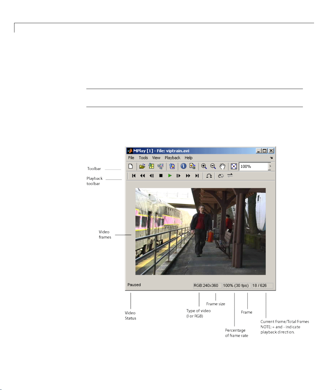
3 Viewing Video
7 Experiment with selecting different signals and viewing them in the
MPlay window. You can also use multiple MPlay GUIs to display different
Simulink signals.
Note During code generation, Real-Time Workshop does not generate code
for the MPlay GUI.
MPlay GUI Interface
The following figure shows the MPlay GUI containing an image sequence.
3-6
Page 95
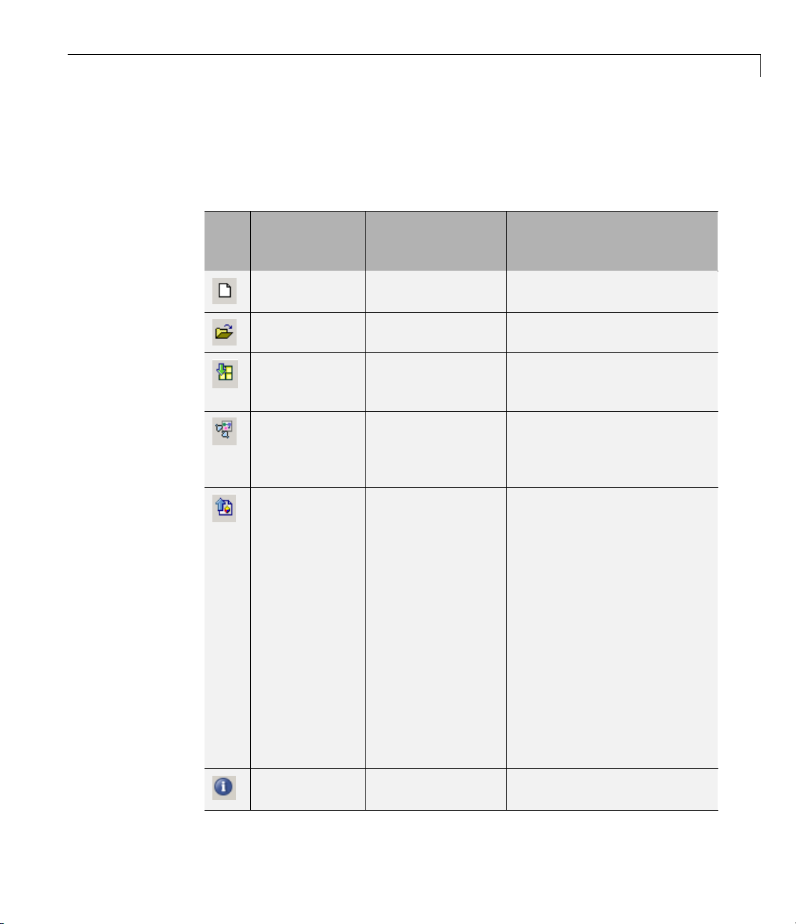
Viewing Video Signals in Simulink
The f ollow ing sections provide descriptions of the MPlay GUI toolbar buttons
and equivalent menu options.
Toolbar Buttons
®
GUI
Menu
Equivalent
File > New
Shortcut Keys
and Accelerators
Ctrl+N Open a new MPlay GUI.
Description
MPlay
File > Open Ctrl+O Connect to a video file.
File >
Import from
Ctrl+I Connect to a variable from the
base MATLAB workspace.
Workspace
File >
Connect t
Simulin
k
o
Connect to a Simulink signal.
Signal
File > Export
to Image Tool
Ctrl+E Send the
frame t
For mor
“Using
Explo
Image
docum
The Im
the f
imag
the f
ay(256)
(
gr
Ima
me is an indexed image
fra
and
ntrast button.
Co
current video
otheImageTool.
e information, see
the Image Tool to
re Images” in the
Processing Toolbox
entation.
age Tool only knows
rame is an intensity
e if the colormap of
rame is grayscale
). Otherwise, the
ge Too l assumes that the
disables the Adjust
Tools > Video
Information
V
ew information about the
Vi
deo data source.
vi
3-7
Page 96

3 Viewing Video
GUI
Menu
Equivalent
Tools > Pixel
Region
Tools > Zoom
In
Tools > Zoom
Out
Tools > Pan
Tools >
Maintain Fit
to Window
N/A N/A
Shortcut Keys
and Accelerators
N/A Open the Pixel Region
N/A
N/A Zoom out of the video display.
N/A
N/A ScalevideotofitGUIsize
Description
tool. For more information
about this tool, see the
Image Processing Toolbox
documentation.
Zoom in on the video display.
Move the image displayed in
the GUI.
automatically. Toggle the
buttononoroff.
Enlarge or shrink the video
display. This option is
available if you do not select
the Maintain Fit to Window
button.
3-8
Playback Toolbar — Workspace and File Sources
GUI
Menu
Equivalent
Playback >
Go to First
Playback >
Rewind
Playback >
Step Back
Shortcut Keys
and Accelerators
F, Home
Up arrow
Left arrow, PageUpStep back one frame.
Description
Go to the first frame of the
video.
Jump back ten frames.
Page 97

Viewing Video Signals in Simulink
®
GUI
Menu
Equivalent
Playback >
Stop
Playback >
Play
Playback >
Pause
Playback
>Step
Forward
Playback >
Fast Forward
Playback >
Go to Last
Playback >
Jump to
Playback >
Playback
Modes >
Repeat
Shortcut Keys
Description
and Accelerators
S Stop the video.
P,Spacebar
P,Spacebar
Play the video.
Pause the vid
appears only
is playing.
Right arrow , Page
Step forwar
doneframe.
Down
Down arrow
L, End
Jump forward ten frames.
Go to the last frame of the
video.
J
R
Jump to a specific frame.
Repeated video playback.
eo. This button
when the video
Playback >
Playback
Modes >
Forward play
A Play the video forward.
3-9
Page 98

3 Viewing Video
GUI
Playback Toolbar — Simulink Sources
GUI
Menu
Equivalent
Playback >
Playback
Modes >
Backwardplay
Playback >
Playback
Modes >
AutoReverse
play
Menu
Equivalent
Playback
Stop
Playba
Start
>
ck >
Shortcut Keys
and Accelerators
A
A Play the video forward and
Shortcut Keys
and Accelerators
S Stop the video. This button
P,Spacebar
Description
Play the video backward.
backward.
Description
also controls the Simulink
model.
Play th
also co
model.
evideo. Thisbutton
ntrols the Simulink
3-10
Playback >
Pause
Playback
>Step
Forward
Playback
> Simulink
Snapshot
P,Spa
Right arrow, Page
Down
N/A Click this button to freeze the
ce bar
Pause the video. This button
also controls the Simulink
model and appears only when
the video is playing.
Step forward one fram e.
This button also controls the
Simulink model.
display in the MPlay window.
Page 99

Viewing Video Signals in Simulink
®
GUI
Config
Menu
Equivalent
Playback >
Highlight
Simulink
Signal
Playback
> Floating
Signal
Connection
(not select
Playback
> Floatin
Signal
Connecti
(select
ed)
uration
g
on
Shortcut Keys
Description
and Accelerators
Ctrl+L
In the model window,
highlight the Simulink
signal the MPlay GUI is
displaying.
N/A Indicates persistent Simulink
connection. In this mode, the
MPlay GUI always associates
with the Simulink signal you
ed)
selected before you clicked
the Connect to Simulink
Signal button.
N/A Indicates floating Simulink
connection. In this mode, you
can click different signals in
the model, and the MPlay
GUI displays them. You can
use only one MPlay GUI in
floating-scope mode at a time.
The MPl
appea
• To ope
• To sa
ay Configuration dialog box en ab les you to change the behavior and
rance of the GUI as well as the behavior of the playback shortcut keys.
n the Configuration dialog box, select File > Configuration
Set > E
dit.
ve the configuration settings for future use, select
> Configuration Set > Save as.
File
e By default, the MPlay GUI uses the configuration settings from the
Not
e
mplay.cfg. Create a backup copy of the file to store your configuration
fil
tings.
set
3-11
Page 100
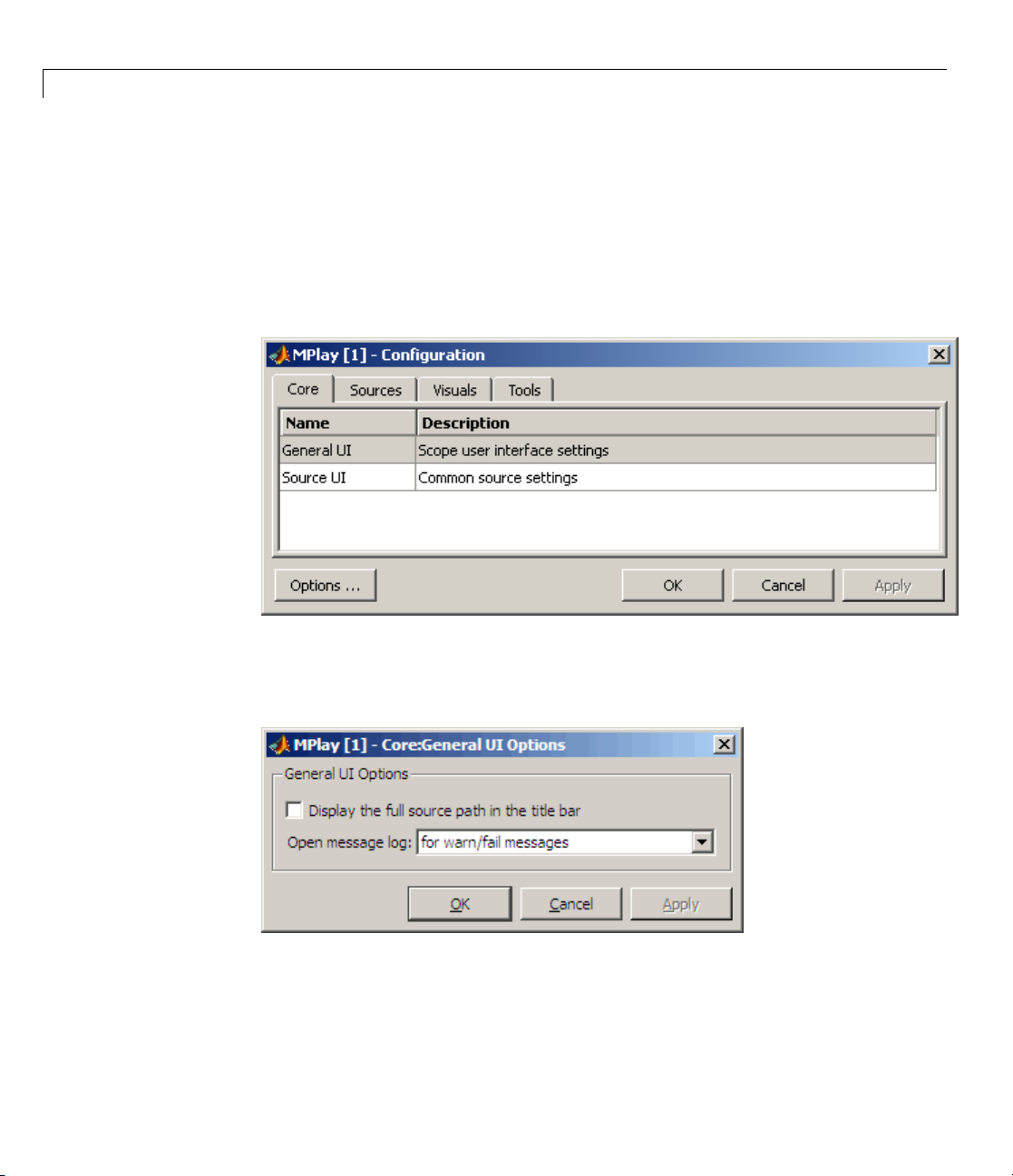
3 Viewing Video
• To load a preexisting configuration set, select File > Configuration
Set > Load.
Configuration Core Pa n e
The Core pane controls the graphic user interface (GUI) general and source
settings.
3-12
General
Click Ge
UI Optio
If you select the Display the full source path in the title bar check box,
the full Simulink path appears in the title bar. Otherwise, the title bar
displays a shortened name.
UI
neral UI, and then select the Options button to open the General
ns dialog box.
 Loading...