

Page 1

Target Support Pac
kage™ 4
User’s Guide
For Use with Texas Instruments C2000™
Page 2

How to Contact The MathWorks
www.mathworks.
comp.soft-sys.matlab Newsgroup
www.mathworks.com/contact_TS.html Technical Support
suggest@mathworks.com Product enhancement suggestions
bugs@mathwo
doc@mathworks.com Documentation error reports
service@mathworks.com Order status, license renewals, passcodes
info@mathwo
com
rks.com
rks.com
Web
Bug reports
Sales, prici
ng, and general information
508-647-7000 (Phone)
508-647-7001 (Fax)
The MathWorks, Inc.
3 Apple Hill Drive
Natick, MA 01760-2098
For contact information about worldwide offices, see the MathWorks Web site.
Target Support Package™ User’s Guide
© COPYRIGHT 2003–2010 by The MathWorks, Inc.
The software described in this document is furnished under a license agreement. The software may be used
or copied only under the terms of the license agreement. No part of this manual may be photocopied or
reproduced in any form without prior written consent from The MathW orks, Inc.
FEDERAL ACQUISITION: This provision applies to all acquisitions of the Program and Documentation
by, for, or through the federal government of the United States. By accepting delivery of the Program
or Documentation, the government hereby agrees that this software or documentation qualifies as
commercial computer software or commercial computer software documentation as such terms are used
or defined in FAR 12.212, DFARS Part 227.72, and DFARS 252.227-7014. Accordingly, the term s and
conditions of this Agreement and only those rights specified in this Agreement, shall pertain to and govern
theuse,modification,reproduction,release,performance,display,anddisclosureoftheProgramand
Documentation by the federal government (or other enti ty acquiring for or through the federal government)
and shall supersede any conflicting contractual terms or conditions. If this License fails to meet the
government’s needs o r is inconsistent in any respect with federal procurement law, the government agrees
to return the Program and Docu mentation, unused, to The MathWorks, Inc.
Trademarks
MATLAB and Simulink are registered trademarks of The MathWorks, Inc. See
www.mathworks.com/trademarks for a list of additional trademarks. Other product or brand
names may be trademarks or registered trademarks of their respective holders.
Patents
The MathWorks products are protected by one or more U.S. patents. Please see
www.mathworks.com/patents for more information.
Page 3

Revision History
November 2003 Online only New for Version 1.0 (Release 13SP1+)
June 2003 Online only New for V ersion 1.1 (Release 14)
October 2004 Online only Revised for Version 1.1.1 (Release 14SP1)
December 2004 Online only Revised for Version 1.2 (Release 14SP1+)
March 2005 Online only Revised for Version 1.2.1 (Release 14SP2)
September 2005 Online only Revised for Version 1.3 (Release 14SP3)
March 2006 Online only Revised for Version 2.0 (Release 2006a)
September 2006 Online only Revised for Version 2.1 (Release 2006b)
March 2007 Online only Revised for Version 2.2 (Release 2007a)
September 2007 Online only Revised for Version 2.3 (Release 2007b)
March 2008 Online only Revised for Version 3.0 (Release 2008a)
October 2008 Online only Revised for Version 3.1 (Release 2008b)
March 2009 Online only Revised for Version 3.2 (Release 2009a)
September 2009 Online only Revised for Version 4.0 (Release 2009b)
March 2010 Online only Revised for Version 4.1 (Release 2010a)
Page 4

Page 5

Getting Started
1
Product Overview ................................. 1-2
Introduction
Product Description
...................................... 1-2
............................... 1-2
Contents
Setting Up and Configuring
System Require ments
Supported Hardware
Installing and Configuring Software
Verifying the Configuration
Code Com poser Studio
Using Code Composer Studio with Target Support Package
Software
Default Project Configuration
Data Type Support
Scheduling and Timing
Overview
Timer-Based Interrupt Processing
Asynchronous Interrupt Processing
Sharing General Purpose Timers between C281x
Peripherals
Example 1
Example 2
....................................... 1-7
........................................ 1-10
..................................... 1-16
....................................... 1-17
....................................... 1-21
.............................. 1-3
............................... 1-3
................................. 1-9
........................ 1-3
.................. 1-3
......................... 1-4
............................. 1-7
....................... 1-7
............................ 1-10
.................... 1-10
................... 1-11
Overview of Creating Models for Targeting
Accessing the Target Support Package Block Library
Online Help
Blocks with Restrictions
Setting Simulation Configuration Parameters
Building Your Model
...................................... 1-26
............................ 1-26
............................... 1-29
.......... 1-25
.... 1-25
.......... 1-28
v
Page 6

Using the c2000lib Blockset ......................... 1-30
Introduction
Hardware Setup
Starting the c2000lib Library
Setting Up the Model
Adding Blocks to the Model
Generating Code from the Model
...................................... 1-30
.................................. 1-30
........................ 1-31
.............................. 1-33
......................... 1-35
..................... 1-38
Configuring Timing Parameters for CAN Blocks
2
The CAN Blocks ................................... 2-2
Setting Timing Parameters
Accessing the Timing Parameters
Determining Timing Parameter Values
CAN Bit Timing Example
Parameter Tuning and Signal Logging
Overview
Using External Mode
Using a Third Party Calibration Tool
........................................ 2-9
......................... 2-3
.................... 2-3
............... 2-6
........................... 2-7
.............. 2-9
.............................. 2-9
................. 2-18
Configuring Acquisition Window Width for ADC
3
What Is an Acquisition Window? .................... 3-2
Configuring ADC Parameters for Acquisition Window
Width
Accessing the ADC Parameters
Examples
.......................................... 3-5
...................... 3-5
........................................ 3-7
Blocks
vi Contents
Page 7

Using the IQmath Library
4
About the IQmath Library .......................... 4-2
Introduction
Common Characteristics
References
...................................... 4-2
............................ 4-3
....................................... 4-3
Fixed-Point Numbers
Notation
Signed Fixed-Point Numbers
Q Format Notation
Building Models
Overview
Converting Data Types
Using Sources and Sinks
Choosing Blo cks to Optimize Code
Double and Single-Precision Param eter Values
......................................... 4-4
........................................ 4-10
.............................. 4-4
........................ 4-5
................................ 4-5
................................... 4-10
............................. 4-10
........................... 4-11
.................... 4-11
......... 4-11
Programming Flash Memory
5
Introduction ...................................... 5-2
Installing TI Flash APIs
............................ 5-3
Configuring the DSP Board Bootloader
Configuring the Software for Automatic Flash
Programming
Selectively Erase, Program, or Verify Specific Flash
Sectors
......................................... 5-7
................................... 5-5
.............. 5-4
vii
Page 8

Placing Additional Code or Data on Unused Flash
Sectors
......................................... 5-8
Block Reference
6
C280x (c280xlib) ................................... 6-2
C2802x (c2802xlib)
C2803x (c2803xlib)
C281x (c281xlib)
C28x3x (c2833xlib)
C28x DMC (c28xdmclib)
C28x IQmath (tiiqmathlib)
Host SCI Blocks (c2000scilib)
RTDX Instrumentation (rtdxBlocks)
Target Preferences (c2000tgtpreflib)
................................. 6-4
................................. 6-6
................................... 6-8
................................. 6-10
............................ 6-12
.......................... 6-13
....................... 6-14
................. 6-15
................ 6-16
viii Contents
Page 9

7
Blocks — Alphabetical List
Index
ix
Page 10

x Contents
Page 11

Getting Started
• “Product Overview” on page 1-2
• “Setting Up and Configuring” on page 1-3
• “Code Composer Studio” on page 1-7
• “Data Type Support” o n page 1-9
• “Scheduling and Timing” on page 1-10
• “Sharing General Purpose Timers between C281x Peripherals” on page 1-16
• “Overview of Creating Models for Targeting ” on page 1-25
1
• “Using the c2000lib Blockset” on page 1-30
Page 12

1 Getting Started
Product Overview
Introduction
This chapter describes how to use Target Support Package™ software
to create and execute applications on Texas Instruments™ C2000™
microcontrollers. To use the targeting software, become familiar with creating
Simulink
for automatic code generation. For more information about these concepts,
refer to the “Real-Time Workshop” documentation.
Product Description
Use Targe t Support Package to deploy generated code for real-time execution
on embedded microprocessors, microcontrollers, and DSPs. Using Target
Support Package, you can integrate peripheral devices and real-time
operating systems with the algorithms created using Embedded MATLAB™,
Simulink®, and Stateflow®. You can deploy the resulting executable onto
embedded hardware for on-target rapid prototyping, real-time performance
analysis, and field production.
In this section...
“Introduction” on page 1-2
“Product Description” on page 1-2
®
models and with the basic concepts of using Real-Time Workshop
®
1-2
Page 13

Setting Up and Configuring
In this section...
“System Requirements” on page 1-3
“Supported Hardware” on page 1-3
“Installing and Configuring Software” on page 1-3
“Verifying the Configuration” on page 1-4
System Requirements
For detailed information about the software and hardware required to use
Target Support Package software, refer to the Target Support Package system
requirements areas on the MathWorks Web site:
• Requirements for Target Support Package:
www.mathworks.com/products/target-package/requirements.html
Setting Up and Configuring
• Requirements for use with TI’s C2000:
www.mathworks.com/products/target-package/ti-adaptor/
Supported Hardware
For a list of supported hardware, visit
http://www.mathworks.com/products/target-package/supportedio.html.
Installing and Configuring Software
Consult the System Requirements for Target Support Package on the
MathWorks website. Only use supported versions of the software listed under
“Third-Party Target Support Package Requirements”. Uninstall unsupported
versions before installing supported versions. Doing so prevents errors that
occur when the Windows Environment Variables points to the unsupported
versions.
The System Requirements Web page describes where you can obtain the
additional third-party software, and when available, provides links for
downloading that software.
1-3
Page 14

1 Getting Started
Requirements for Target Support Package:
www.mathworks.com/products/target-package/requirements.html
Install the software listed in the following order:
1 Install the required and optional MathWorks software. (The software
license y ou purchase determines which products are available.)
2 Install TI Code Composer Studio™ (CCS).
3 Install TI Service Release for CCS.
4 Install the TI Code Generation Tools for Windows.
5 If you are using a Spectrum Digital board, download and install the
matching Spectrum Digital Driver.
6 If you are using RTDX for C28x host/target communications, download
and install TI DSP/BIOS.
1-4
7 If you are going to program flash memory with stand-alone code, download
the TI Flash API for your target processor.
Configure CCS as follows:
1 In CCS, open Help > About > Component manager > Build tools >
TMS320C28XX and select (check) C2000 Code Generation Tools.
2 With the Component manager o pen, open Target Content(DSP/BIOS) >
TMS320C28XX and select Texas Instruments DSP/BIOS.
3 Save, exit, and restart CCS.
Verifying the Configuration
To determine whether Target Support Package software is present on your
system, enter this command at the MATLAB
c2000lib
MATLAB displays the C2000 block libraries, as shown here:
®
prompt:
Page 15

Setting Up and Configuring
If you do not see the listed libraries, or MATLAB does not recogniz e the
command, install the Target Support Package software. Without the software,
you cannot use Simulink and Real-Time Workshop software to develop
applications targeted to the TI boards.
To verify that Code Composer Studio (CCS) is present on your machine, enter
this command at the MATLAB prompt:
ccsboardinfo
With CCS installed and configured, MATLAB returns a list of the boards that
CCS recognizes on your machine like the following example:
Board Board Proc Processor Processor
Num Name Num Name Type
--- ---------------------------------- --1 F2812 Simulator 0 CPU TMS320C28xx
0 F2812 PP Emulator 0 CPU_1 TMS320C28xx
1-5
Page 16

1 Getting Started
If M ATLAB does not return information about any boards, revisit your CCS
installation and setup in your CCS documentation.
As a final test, launch CCS to e n sure that it starts up successfully. For Target
SupportPackagesoftwaretooperatewithCCS,theCCSIDEmustbeableto
runonitsown.
Note For any model to work in the targeting environment, select the
discrete-time solver in the Solver pane of the Simulink Configuration
Parameters dialog box. Targeting does not work with continuous-time solvers.
To select the discrete-time solver, from the main menu in your model window,
select Simulation > Configuration Parameters.ThenintheSolver pane,
set the Solver option to
Discrete (no continuous states).
1-6
Page 17

Code Composer Studio
In this section...
“Using C ode Composer Studio with Target Support Package Software” on
page 1-7
“Default Project Configuration” on page 1-7
Using Code Composer Studio with Target Support Package Software
Texas Instruments (TI) facilitates development of software for TI DSPs by
offering Code Composer Studio (CCS) Integrated Development Environment
(IDE). Used in combination with Target Support Package software a nd
Real-Time Workshop software, CCS provides an integrated environment that,
once installed, requires no coding.
Executing code generated from Real-Time Workshop software on a particular
target requires that you tailor the code to the specific hardware target.
Target-specific code includes I/O device drivers and interrupt service routines
(ISRs). The software must use CCS to compile and link the generated source
code in order to load and execute on a TI DSP. To help you to build an
executable, Target Support Package software uses Embedded IDE Link™
software to start the code building process within CCS. After you download
your executable to your target and run it, the code runs wholly on the target.
You can access the running process only from the CCS debugging tools or
acrossalinkusingEmbeddedIDELinksoftware.
Code Composer Studio™
Default Project Configuration
CCS offers two standard project configurations, Re leas e and Debug. Project
configurations define sets of project build options. When you specify the build
options at the project level, the options apply to all files in your project. For
more information about the build options, refer to your TI documentation.
The models you build with Target Support Package software use a custom
configuration that provides a third combination of build and optimization
settings —
CustomMW.
1-7
Page 18

1 Getting Started
Default Build Options in the CustomMW Configuration
The default settings for CustomMW are the same as the Release project
configuration in CCS, except f or the compiler options.
Your CCS documentation provides complete details on the compiler build
options. You can change the individual settings or the build configuration
within CCS.
1-8
Page 19

Data Type Support
TI C2000 DSPs support 16 and 32–bit data types, but does not have native
8-bit data types. Simulink models and Target Support Package software
support many data types, including 8-bit data types.
Data Type Support
If you select
data, but in the generated code, that data will be represented as 16-bit. This
may cause instances where data overflow and wraparound occurs in the
simulation, but not in the generated code.
For ex ample, to make the ov erflo w behavior of the simulation and generated
code match for a Simulink Add block in your model, select Saturate on
integer overflow in that block.
int8 or uint8 in your model, your simulation runs with 8-bit
1-9
Page 20

1 Getting Started
Scheduling and Timing
In this section...
“Overview” on page 1-10
“Timer-Based Interrupt Processing” on page 1-10
“Asynchronous Interrupt Processing” on page 1-11
Overview
Normally the code generated by Target Support Package software runs in
the context of a timer interrupt. Model blocksruninaperiodicalfashion
clocked by the periodical interrupt whose period is tied to the base sample
time of the model.
This execution scheduling model, however, is not flexible enough for many
systems, especially control and communication systems, which must respond
to external events in real time. Such systems require the ability to handle
various hardware interrupts in an asynchronous fashion.
1-10
Target Support Package software lets you model and generate code for such
systems by creating tasks driven by Hardware Interrupt blocks in addition to
thetasksthatarelefttobehandledinthecontextofthetimerinterrupt.
Timer-Based Interrupt Processing
For code that runs in the context of the timer interrupt, each iteration of
the model solver is run after an interrupt has been posted and serviced by
an interrupt service routine (ISR). The code generated for the C280x, C281x,
and C28x3x uses
The t im er is configured so that the model’s base rate sample time corresponds
to the interrupt rate. The timer period and prescaler are calculated and set
up to ensure the desired rate as follows:
BaseRateSampleTime
CPU_timer0.
=
TimerClockSpeed
TimerPeriod
Page 21

Scheduling and Timing
The minimum achievable base rate sample time depends on the model
complexity. The maximum value depends on the maximum timer period value
32
(2
-1 for the F2812, F2808, and F28x35) and the CPU clock speed. The CPU
clock speed is 100 MHz for the F2808, and 150 MHz for the F2812 and F28335.
If all the blocks in the model inherit their sample time value, and no sample
time is explicitly defined, the default value is 0.2 s.
High-Speed Peripheral Clock
The Event Managers and their general-purpose timers, which drive PW M
waveform generation use the high-speed peripheral clock (HISCLK). By
default, this clock is always selected in Target Support Package software.
This clock is derived from the system clock (SYSCLKOUT):
HISCLK = [SYSCLKOUT / (high-speed peripheral prescaler)]
The high-speed peripheral prescaler is determined by the HSPCLK bits
set in SysCtrl. The default value of HSPCLK is 1, which corresponds to a
high-speed peripheral prescaler value of 2.
For e xample, on the F2812, the HISCLK rate becomes
HISCLK = 150 MHz / 2 = 75 MHz
Asynchronous Interrupt Processing
Simulink and Real-Time Workshop software facilitate the modeling and
generation of code for asynchronous event handling, including servicing of
hardware-generated interrupts, by using the following special blocks:
• Hardware Interrupt block
This block enables selected hardware interrupts, generates the
corresponding interrupt service routines (ISRs), and connects them to the
corresponding interrupt service vector table entries. When you connect
the output of the Hardware Interrupt block to the control input of a
triggered subsystem (for example, a function-call subsystem), the generated
subsystem code is called from the ISRs.
Target Support Package software provides a Hardware Interrupt block for
each of the supported processor families.
1-11
Page 22

1 Getting Started
• Rate Transition blocks
These blocks support data transfers between blocks running with different
sample rates. The built-in Simulink Rate Transition blocks can be used
for this purpose.
The following diagram illustrates a use case where a Hardware Interrupt
block triggers two tasks, connected to other blocks that run periodically in the
context of the synchronous scheduler.
1-12
In the p
interr
and the
Hardw
subsy
execu
The f
eCAN
1 Place the eCAN Receive block in a function-call subsystem, as shown in
receding figure, the Hardware Interrupt block is set to react on two
upts. Since only one Hardware Interrupt block is allowed in a model
output of this block is a vector of length two, you must connect the
are Interrupt block to a Demux block to trigger the two function-call
stems. The function-call subsystems contain the blocks that are
ted asynchronously in the context of the hardware interrupt.
ollowing example shows how to build and configure a model to react on an
message using a hardware interrupt and an asynchronous scheduler:
the following figure.
Page 23

Scheduling and Timing
2 On the eCAN Receive block dialog, check the box labeled Post interrupt
when message is received, as shown in the following figure.
3 Set the Sample Time of the eCAN Receive block to -1 s ince the block will
be triggered by the ISR, as shown in the preceding figure.
1-13
Page 24

1 Getting Started
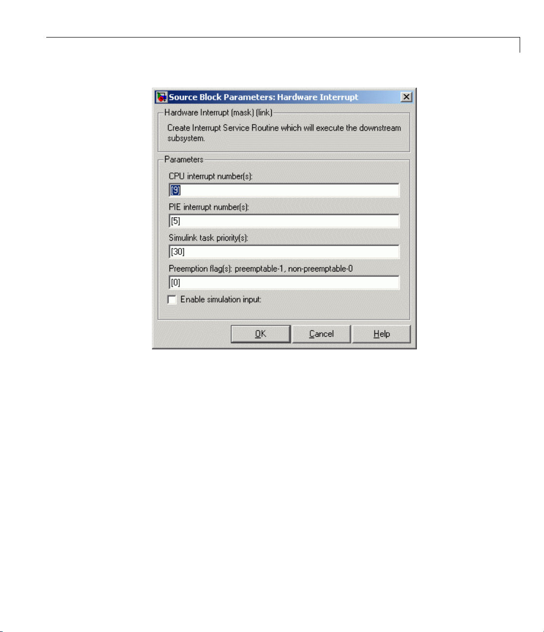
4 Add the C281x Hardware Interrupt block to your model, as shown in the
following figure.
5 The eCAN interrupt on C281x chips is on CPU line 9 and PIE line 5
for module 0 . These parameters canbefoundintheC281xHardware
Interrupt block, C281x P eripheral Interrupt Vector Values figure. Set the
hardware interrupt param eters CPU interrupt number(s): to
interrupt number(s): to
5 as shown in the following figure.
9,andPIE
1-14
Page 25
Scheduling and Timing
6 Connec
subsys
At exec
inter
is exe
funct
to the
For m
Real
t the output of the Hardware Interrupt block to the function-call
tem containing the eCAN block.
ution time, when a new eCAN message is received, the eCAN
rupt is triggered, and the code you placed in the function-call subsystem
cuted. In this example, the eCAN Receive block is placed in the
ion-call subsystem, which means that the message is read and is passed
rest of the code.
ore information, see the section on Asynchronous Support in the
-Time Workshop documentation.
1-15
Page 26

1 Getting Started
Sharing General Purpose Timers b etween C281x Peripherals
TMS320x281x DS
Event Manager (
• EVA includes G
• EVB includes G
You can use th
with the EV M
The followi
block libra
GP Timer Us
PWM1-PWM
PWM7-PWM12
QEP1-QEP2
QEP3-QEP4
CAP1-CAP3
CAP4-CAP6
e GP Timers independently or to operate peripherals associated
anager, such as PWM, QEP, and CAP.
ng table describes the timer-peripheral mapping of the c281xlib
ry.
e for C281x Peripheral Blocks
GP Timer 1 GP Timer 2 GP Timer 3 GP Timer 4
6
P devices have four General Purpose (GP) timers. Each
EV) module includes two GP timers:
PTimer1andGPTimer2.
PTimer3andGPTimer4.
1-16
PWM and QEP peripheral has access to only one timer, while each CAP
Each
pheral has access to two timers. In the PWM and QEP blocks, you ca n
peri
the Module option to
set
bination the block configures. By comparison, in the CAP block, you can
com
the Time base option to select one of two timers for each CAP peripheral.
use
ch GP timer is available to multiple peripherals. For example:
Ea
M1-PWM6andCAP1-CAP3shareGPTimer1
• PW
WM7-PWM12 and CAP4-CAP6 share GP Timer 3
• P
A or B to determine which unique timer-peripheral
Page 27
Sharing General Purpose Timers between C281x Peripherals
• QEP1-QEP2 and CAP1-CAP3 share GP Timer 2
• QEP3-QEP4 and CAP4-CAP6 share GP Timer 4
ThePWM,QEP,CAP,andTimerblockseach provide independent access to
key timer registers. If the blocks in your model share a specific GP timer,
ensure that all the timer-related settings are compatible. If the peripheral
settings for a shared timer are not compatible, the software generates an
error when you update the model or ge nerate code.
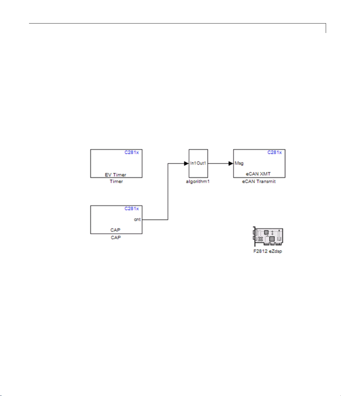
Example 1
The model contains Timer and CAP blocksthatbothuseTimer1(GPTimer1).
1-17
Page 28
1 Getting Started
1-18
Page 29

Sharing General Purpose Timers between C281x Peripherals
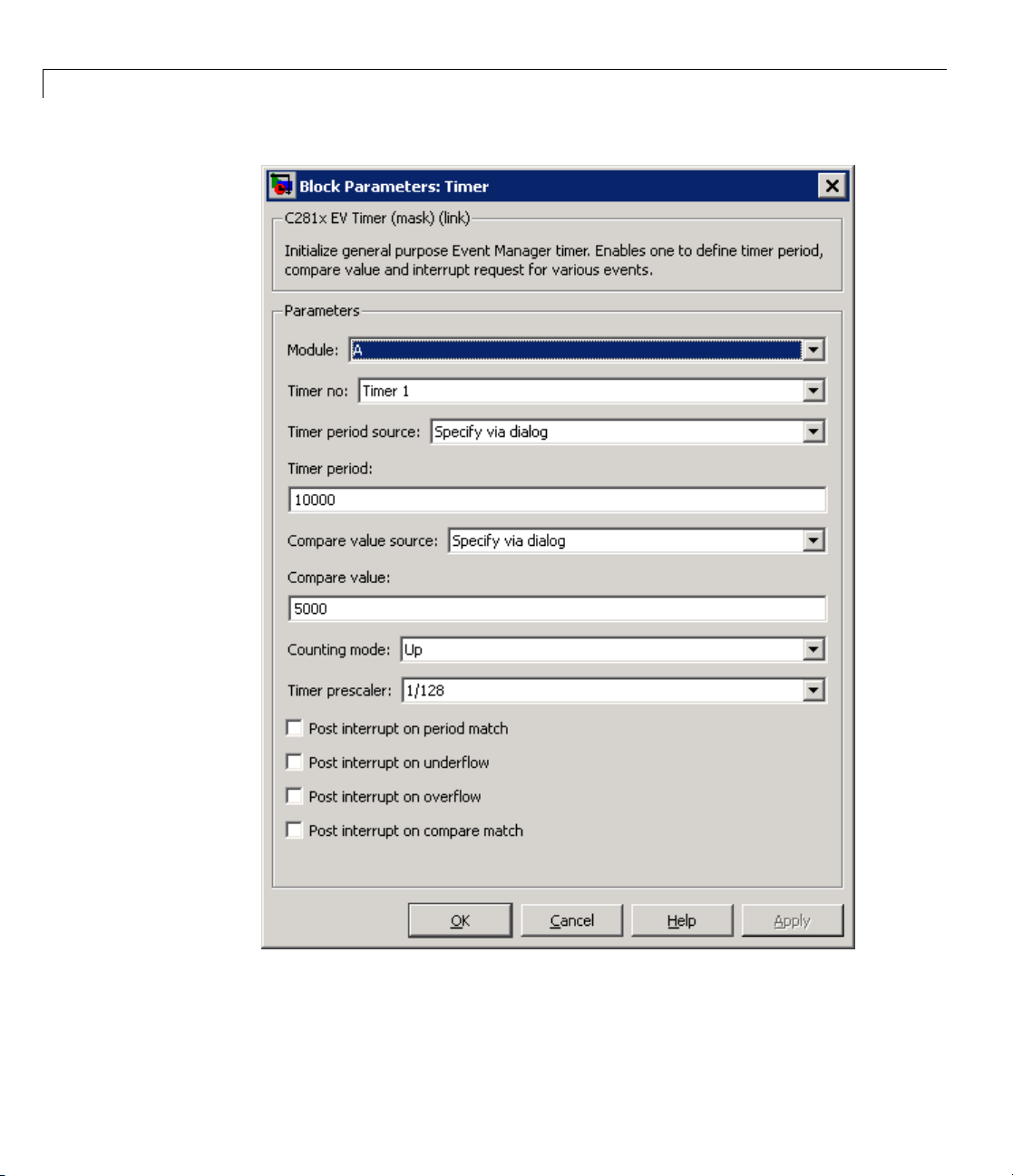
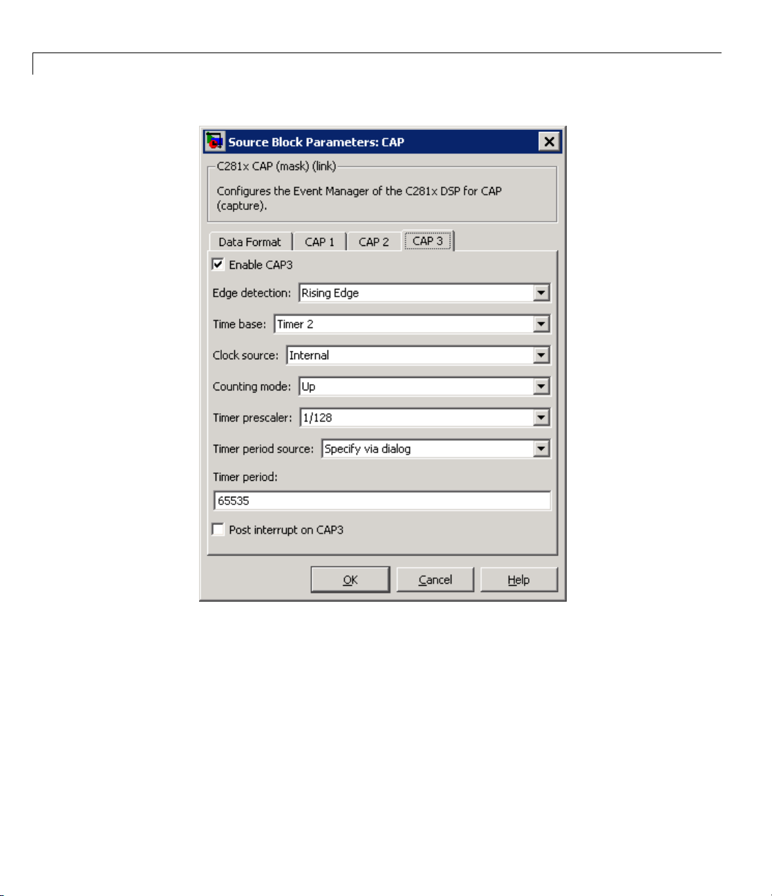
Both blocks have the same values for Timer prescaler and Counting
mode. However, each block has different values for Timer period.The
value of Timer period for Timer 1 is
65535 in the CAP block and 10000 in
the Timer block.
1-19
Page 30

1 Getting Started
1-20
Since both blocks configure the same timer, and settings conflict, the software
generates an error when you update the model.
Page 31

Example 2
Sharing General Purpose Timers between C281x Peripherals
The model
block, th
block, s
Timer Us
use Time
e Time base option shows which timer the block uses. In the QEP
etting Module to
contains QEP and CAP blocks that both use Timer 2. In the CAP
A configures the block to use QEP1–QEP2. GP
e for C281x Peripheral Blocks on page 1-16 shows that QEP1–QEP2
r2.
1-21
Page 32
1 Getting Started
1-22
Page 33

Sharing General Purpose Timers between C281x Peripherals
Currently, both blocks define different clock sources f or Timer 2. The CAP
block uses
Internal as a Clock source. The QEP block, which does not have
aconfigurableClock source setting, uses the QEP circuit as a clock source.
If you build the model, the software generates the following error message.
1-23
Page 34

1 Getting Started
1-24
To avoid generating errors when you build the model, change Clock source
in the CAP block to
QEP device.
Page 35

Overview of Creating Models for Targeting
Overview of Creating Models for Targeting
In this section...
“Accessing the Target Support Package Block Library” on page 1-25
“Online Help” on page 1-26
“Blocks with Re s triction s” on page 1-26
“Setting Simulation Configuration Parameters” on page 1-28
“Building Your Model” on page 1-29
Accessing the Target Support Package Block Library
After you have installed the supported developm ent board, start MATLAB. At
the MATLAB command prompt, type
c2000lib
This opens the c2000lib Simulink blockset that includes li braries containing
blocks predefined for C2000 input and output devices. As needed, add the
blocks to your model. See “Using the c2000lib Blockset” on page 1-30 for an
example of how to use this library.
Create your real-time model for your application the s ame way you create any
other Simulink model. Select blocks to build your model from the following
sources or products:
• The appropriate Target Preferences library block (for setting target and
application preferences)
• The appropriate libraries in the
and output functions for on your target hardware)
• Real-Time Workshop software
• Discrete time blocks from Simulink
• Any other blockset that meets your needs and operates in the discrete
time domain
c2000lib block library (for handling input
1-25
Page 36

1 Getting Started
Online Help
To get general he
in MATLAB. At the
help tic2000
lp for Target Support Package software, use the help feature
command prompt, type
to list the fun
software. Or s
in the MATLAB
Support Pack
Blocks with
Some blocks
for that re
have restr
communica
listed in
ctions and block libraries included in Target Support Package
elect Help > Full Product Family Help from the menu bar
desktop. When you see the C ontents in Help, select Target
age.
Restrictions
may not work on the target as they do on your desktop, and
ason, you should avoid them altogether. Other blocks may
ictions in their settings, which, when followed, ensure smooth
tions. All the blocks that require this special consideration are
the following sections.
Blocks to Avoid Using in Your Models
The bloc
the targ
process
The Mat
the Sco
you use
Library Category Block Name
Simulink
ks listed in the table below generate code, but they do not work on
et as they do on your desktop—in general, they slow your signal
ing application without adding instrumentation value. For this reason,
hWorks recommends that you avoid using certain blocks, such as
pe block and some source and sink blocks, in Simulink models that
for TI C2000 DSP targets.
Sinks
Scope
1-26
Sources
le
To Fi
To Workspace
From File
From Workspace
Page 37

Overview of Creating Models for Targeting
Library Category Block Name
Signal Processing
Blockset™
Signal Operations Triggered Signal From
Workspace
Signal Processing Sinks
Signal To Workspace
Spectrum Scope
Triggered to Workspace
To Wave Device
Signal Processing
Sources
Signal From Workspace
From Wave Device
Blocks That Require Specific Settings
Any block listed in the following table can be used with all your models.
However, such a block requires specific settings, as indicated under
“Restriction.”
Library
Signal
Processing
Blockset
Category
Signal
Processing
Sources
Block
Name
Random
Source
Block
Restriction
For this block, the only Outpu t data
type supported by the TI C2000 is
Single.Besuretosetthisparameter
correctly in the Block Parameters
dialog box. See the following figure.
1-27
Page 38

1 Getting Started
Setting Simulation Configuration Parameters
When you drag a Target Preferences block into your model, you are given the
option to set basic simulation parameters automatically.
To re fin e the automatic settings, or set the simulation parameters manually,
open your model and select Simulation > Configuration Parameters.
If you are setting your simulation parameters manually, you must make
at least the following two settings:
• You must specify discrete time by selecting
continuous states)
dialog box.
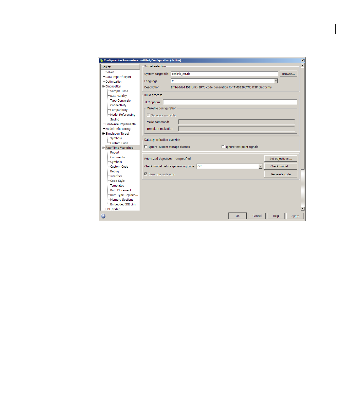
• You must also specify the appropriate version of the system targ et file in
the Real-Time Workshop pane. For Target Support Package softw a re,
specify one of the following system target files, or click Browse and select
from the list of targets.
ccslink_grt.tlc
ccslink_ert.tlc
The associated template filename is automatically filled in.
in the Solver pane of the Configuration Parameters
Fixed-step and Discrete (no
System Target Types and Memor y Management
There are two system target types that apply to Target Support Package
software. These correspond to the two system target files mentioned above.
A Generic Real-Time (GRT) target (such as
configuration that generates model code for a re al-time system as if the
resulting code was going to be executed on your workstation.
An Embedded Real-Time (ERT) target (such as
the target configuration that generates model code for execution on an
independent embedded real-time system. This option requires Real-Time
Workshop Embedded Coder.
ccslink_grt.tlc)isthetarget
ccslink_ert.tlc)is
1-28
The ERT target for Target Support Package software offers memory
management features that give you a way manage the performance o f your
code while working with limited memory resources. For more information
Page 39

Overview of Creating Models for Targeting
on this, see the chapter on Memory Sections in the Real-Time Workshop
Embedded Coder User’s Guide.
Building Your Model
With this configuration, you can generate a real-time executable and
download it to your TI development board by clicking Generate Code on the
Real-Time Workshop pane. Real-Time Workshop software automatically
generates C code and inserts the I/O device drivers as specified by the
hardware blocks in your block diagram, if any. These device drivers are
inserted in the generated C code.
During the same build operation, block parameter dialog box entries are
combined into a project file for CCS for your TI C2000 board. If you selected
the
Build and execute build action in the configuration settings, the TI
cross-compiler builds an executable file. After automatically dow n loading the
executable file to the target, the build process runs the file on the board’s DSP.
Note After using the run-time Build option to generate and build code for
your application, you must perform the following reset sequence before you
can run that code on your board. If you w an t to rerun your application
manually once it has been generated, you must also use this procedure.
F2812, F2808, and F28335 eZdsp Reset Sequence
1 Reset the board CPU.
2 Load your code onto the target.
3 Run your code on the target.
1-29
Page 40

1 Getting Started
Using the c2000lib Blockset
In this section...
“Introduction” on page 1-30
“Hardware Setup” on page 1-30
“Starting the c2000lib Library” on page 1-31
“Setting Up the Model” on page 1-33
“Adding Blocks to the Model” on page 1-35
“Generating Code from the Model” on page 1-38
Introduction
This section uses an example to demonstrate how to create a Simulink model
that uses Target Support Package blocks to target your board. The example
creates a model that performs PWM duty cycle control via pulse width change.
It uses the C2812 ADC block to sample an analog voltage and the C2812
PWM block to generate a pulse waveform. The analog voltage controls the
duty cycle of the PWM and you can observe the duty cycle change on the
oscilloscope. This model is also provided in the Demos library. The model in
the Demos library also includes a model simulation.
1-30
Hardware Setup
The following hardware is needed for this example:
• Spectrum Digital eZdsp F2812
• Function generator
• Oscilloscope and probes
To connect the hardware:
1 Connect the function generator output to the ADC input ADCINA0 on
the eZdsp F2812.
2 Connect the output of PWM1 on the eZdsp F2812 to the analog input of
the oscilloscope.
Page 41

Using the c2000lib Blockset
3 Connect VREFLO to AGND on the eZdsp F2812. See the section
on the Analog Interface in Chapter 2 of the eZdsp™ F2812
Technical Reference, available from the Spectrum Digital website at
http://c2000.spectrumdigital.com/ezf2812/
Starting the c2000lib Library
At the MA TLAB prompt, type
c2000lib
to open the c2000lib library blockset, which contains libraries of blocks
designed for targeting your board.
The libraries are in three groups, plus Info and Demos blocks.
General
• C2000 RTDX Instrumentation (rtdxBlocks)—BlocksforaddingRTDX
communications channels to Simulink m odels. See the tutorial in
Embedded IDE Link documentation for an example of using these blocks.
1-31
Page 42

1 Getting Started
• C2000 Target Preferences (c2000tgtpreflib)—BlockstospecifyTarget
Preferences and options. You do not connect this block to any other block in
your model.
• Host-side CAN Blocks (
canmsglib) — Blocks to configure CAN message
blocks.
• Host SCI Blocks (
c2000scilib) — Blocks to configure host-side serial
communications interface to send and receive data from serial port
Chip Support
• C280x (c280xlib) — Blocks to configure the F2808 eZdsp DSK or on
C280x-based custom boards
• C281x (
C281x-based custom boards
• C28x3x (
C28x3x-based custom boards
• C2802x (
C2802x-based custom boards
• C2803x (
C2803x-based custom boards
• Custom C2000 (
boards
c281xlib) — Blocks to configure the F2812 eZdsp DSK or on
c2833xlib) — Blocks to configure the F2833 eZdsp DSK or on
c2802xlib) — Blocks to configure t he C2802x eZdsp DSK or on
c2803xlib) — Blocks to configure t he C2803x eZdsp DSK or on
c2000xlib) — Blocks to configure C2000-based custom
1-32
Optimized Libraries
The Optimization library, c2000optimized blks,contains:
• C28x IQmath Library (
with C28x targets
• C28x DMC Library (
motor control with C28x DSPs
tiiqmathlib)—Fixed-pointmathblocksforuse
c28xdmclib) — Fixed-point math blocks for digital
Page 43

Using the c2000lib Blockset
Setting Up the Mo
Preliminary tas
Preferences blo
simulation par
1 In the Library
new Simulink m
2 In the Library: c2000lib window, double-click the C2000 Target Preferences
ks for setting up a new model include adding a Target
ck, setting or verifying Target Preferences, and setting the
ameters.
: c2000lib window, select File>New>Modelto create a
odel.
del
library block.
3 From the Target Preferences Library window, drag the F2812 eZdsp block
into your new model.
4 Click Yes to allow automatic setup. The following settings are
made, re ferenced in the table below by their locations in the
Simulation > Configuration Parameters dialog box:
Pane Field Setting
Solver Stop ti
Solve
Data
r
Type
Save t
me
o workspace - Time
10
Fixed
tout
-step
Import/Export
Data
Import/Export
dware
Har
plementation
Im
Real-Time
Workshop
Save to workspace Output
Device type
rget selection - System
Ta
rget file
ta
yout
C2000
slink_grt.tlc
cc
r
o
cslink_ert.tlc
c
1-33
Page 44

1 Getting Started
Note Generated code does not honor Simulink stop time from the
simulation. Stop time is interpreted as
generated code, you must put a Stop Simulation block in your model.
Note One Target Preferences block must be in each target model at the top
level. It does not connect to any other blocks, but stands alone to set the
Target Preferences for the model.
5 From your model’s main menu, select Simulation > Configuration
Parameters to verify and set the simulation p arameters for this model.
Parameters you set in this dialog box belong to the model you are building.
They are saved with the model and stored in the model file. R efer to your
Simulink documentation for information on the Configuration Parameters
dialog box.
6 Use the Real-Time Workshop pane to set options for the real-time
model. Refer to your “Real-Time Workshop” documentation for detailed
information on the Real-Time Workshop pane options.
inf. To implement a stop in
1-34
Page 45
Using the c2000lib Blockset
7 Use the Browse button to locate and select a target configuration file,
ccslink_grt.tlc or ccslink_ert.tlc. When you do this, Real-Time
Workshop software chooses the appropriate system target file, and
make
command.
8 Set the configuration parameters by typing Ctrl-E and adjust
these parameters. For descriptions of these fields, see the Target
Preferences/Custom Board reference page and “Setting Simulation
Configuration Parameters” on page 1-28 in the section titled “Overview of
Creating Models for Targeting” on page 1-25.
Adding Blocks to the Model
1 Open or double-click the C281x library, c281xlib.
1-35
Page 46

1 Getting Started
1-36
2 Drag th e C281x ADC block into your model. Double-click the ADC block
in the model and set Sample time to
for all other fields. Refer to the C281x ADC reference page for information
on these fields.
64/80000.Usethedefaultvalues
Page 47

Using the c2000lib Blockset
3 Drag the C281x PWM block into your model. Double-click the PWM block
in the model and set the follow ing parameters. Refer to the C281x PWM
reference page for informationonthesefields.
Pane Field Parameter
Timer
Module
Waveform
A
Specify via dialog
period source
Waveform
Clock cycles
period units
Waveform
64000
period
Waveform type
Asymmetric
Outputs
Enable
Selected
PWM1/PWM2
Duty cycle
Input port
source
Logic
PWM1 control
Active high
logic
PWM2 control
Active low
logic
Deadband
Use
Selected
deadband for
PWM1/PWM2
Deadband
16
prescaler
Deadband
12
period
ADC Control ADC start event
4 Enter Simulink at the MATLAB command line to open the Simulink
Period interrupt
Library browser. Drag a Gain block from the Math Operations library into
your model. Double-click the Gain block in the model and set the following
parameters in the Function Block Parameters dialog box. Click OK.
1-37
Page 48

1 Getting Started
Pane Field Parameter
Main
Signal Attributes
Parameter
Attributes
5 ConnecttheADCblocktotheGainblockandtheGainblocktothePWM
block as shown:
Gain
Multiplication
Sample time
Output data type
mode
Integer rounding
mode
Parameter data type
mode
30
Element-wise(K.*u)
-1
uint(16)
Floor
Inherit from input
1-38
Generating Code from the Model
This section summarizes how to generate code from your real-time model. For
details about generating code from models in Real-Time Workshop software,
refer to the “Real-Time Workshop” documentation.
You start the automatic code generation process from the Simulink model
window by clicking Generate code in the Real-Time Workshop pane of the
Configuration Parameters dialog. Other ways of starting the code generation
process are by clicking the Incremental Build buttononthetoolbarof
your model, or by pressing the keyboard shortcut, Ctrl+B, while your model
is open and in focus.
Note InCCS,youseeyourprojectwiththefilesinplaceinthefolder
structure.
Page 49

2
Configuring Timing Parameters for CAN Blocks
• “The CAN Blocks” on page 2-2
• “Setting Timing Parameters” on page 2-3
• “Parameter Tuning and Signal Logging” on page 2-9
Page 50

2 Config uring Timing Parameters for CAN Blocks
The CAN Blocks
The bit rate of these four CAN blocks cannot be set directly:
C281x eCAN Rece
C281x eCAN Transmit
C280x/C28x3x eCAN Receive
C280x/C28x3x
ive
eCAN Transmit
2-2
Page 51

Setting Timing Parameters
In this section...
“Accessing the Timing Parameters” on page 2-3
“Determining Timing Parameter Values” on page 2-6
“CAN Bit Timing Example” on page 2-7
Accessing the Timing Parameters
Tosetthebitratefor“TheCANBlocks”:
1 Confirm that your model includes the appropriate Target Preferences block
from the C2000 Target Preferences Library.
2 Double click the Target Preferences block in your model. This opens the
Target Preferences dialog box.
Setting Timing Parameters
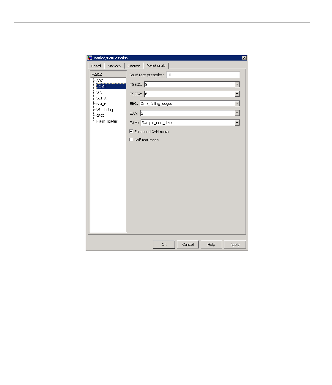
3 Under th
BaudRat
For exa
box is s
mple, the Target Preferences block for the F2812 eZdsp, this dialog
hown in the following figure.
e Peripherals tab, use the TSEG1, TSEG2,and
ePrescaler (BRP) parameters to set the bit rate.
2-3
Page 52
2 Config uring Timing Parameters for CAN Blocks
2-4
The C280x/C28x3x blocks have two independent eCAN modules, as shown by
the Target Preferences Setup dialog box.
Page 53

Setting Timing Parameters
The following sections describe the series of steps and rules that govern the
process of setting these timing parameters.
2-5
Page 54

2 Config uring Timing Parameters for CAN Blocks
Determining Tim
To determine the
following steps
1 Determine the C
2 Determine the frequency of the CAN module clock. For example:
:
ing Parameter Values
appropriate values for the timing para meters, comple te the
AN Bitrate specification based on your application.
• 100 MHz for the F2808 (Same as SYSCLKOUT)
• 150 MHz for the F2812 (Same as SYSCLKOUT)
• 75 MHz for the F28x3x (150 MHz SYSCLKOUT/2)
3 Estimate th
4 Solve this equation for BitTime:
evalueoftheBaudRatePrescaler (BRP).
BitTime = CAN module clock frequency/(BRP * Bitrate)
5 Solve thi
s equation for Bitrate:
Bitrate=CANmoduleclockfrequency/(BRP*BitTime)
6 Estimate values of TSEG1 and TSEG2 that satisfy the following equation:
BitTime TSEG TSEG=++121
2-6
7 Use the following rules to determine the values of TSEG1and TSEG2:
TSEG1 >= TSEG 2
IPT (Information Processing Time) = 3/BRP
IPT <=
TSEG1 <= 16 TQ
IPT <= TSEG2 <= 8 TQ
1TQ<=SJW <= min (4 TQ, TSEG2)
where IPT is Information Processing Time, TQ is Time Quanta, and SJW
is Synchronization Jump Width, also set in the Target Preferences
dialog box. .
rate steps 4 through 7 until the values selected for TSEG1, TSEG2, and
8 Ite
P meet all of the criteria.
BR
Page 55

Setting Timing Parameters
The following illustration shows the relationship between the eCAN bit
timing parameters.
CAN Bit Timing Example
Assume that SYSCLKOUT = 150 MHz, and a bit rate of 1 Mbits/s is required.
1 Set the BRP to 10. Then substitute the values of bit rate, BRP, and
SYSCLKOUT into the following equation, solving for BitTime:
BitTime SYSCLKOUT BRP Bitrate
BitTime TQ
2 Set the values of TSEG1 and TSEG2 to 8TQ and 6TQ respectively.
Substitute the values of BitTime from the previous equation, and the
chosen values for TSEG1 and TSEG2 into the following equation:
BitTime TSEG TSEG
TQ TQ TQ
15 8 6 1
3 Finally, check the selected values against the rules:
IPT = 3/BRP = 3/10 = .3
=
==
/( * )150 10 1 15
=++
121
/( * )
=++
2-7
Page 56

2 Config uring Timing Parameters for CAN Blocks
IPT <= TSEG1 <= 16 TQ True! .3<=8TQ<=16TQ
IPT <= TSEG2 <= 8TQ True! .3 <= 6TQ <= 8TQ
1TQ <= SJW <= min(4TQ, TSEG2)whichmeansthatSJW can be set to
either 2, 3, or 4
4 All chosen values satisfy the criteria, so no further iteration is necessary.
The following table provides common timing parameter settings for typical
values of Bit Rate and SYSCLKOUT = 150MHz. This clock frequency is the
maximum for the C281x blocks.
Bit Rate
.5 Mbit/s
1Mbit/s
2Mbit/s
The following table provides common timing parameter settings for typical
values of Bit Rate and SYSCLKOUT = 100MHz. This clock frequency is the
maximum for the C280x/C28x3x blocks.
Bit Rate
.5 6 3 10202
1
2631052
TSEG1 TSEG2
8 6 15202
8 6 15102
861552
TSEG1 TSEG2
5
4
Bit Time
Bit Time
10 10 2
BRP
BRP
SJW
SJW
2-8
Page 57

Parameter Tuning and Signal Logging
In this section...
“Overview” on page 2-9
“Using External Mode” on page 2-9
“Using a Third Party Calibration Tool” on page 2-18
Overview
Target Support Package software supports parameter tuning and signal
logging either using Simulink external mode or with a third party calibration
tool. In both cases the model must include a CAN Calibration Protocol block.
Using External Mode
The Simulink external mode feature enables you to log signals and tune
parameters without requiring a calibration tool. This section describes the
steps for converting a model to use external mode.
Parameter Tuning and Signal Logging
External mode is supported using the CAN Calibration Protocol block and
ASAP2 interface. The CAN Calibration Protocol block is used to communicate
with the target, download parameter updates, and upload signal informa t ion.
The ASAP2 interface is used to get information about where in the target
memory a parame ter or signal lives.
Note You must configure the host-side CAN application channel. See
“Configuring the Host Vector CAN Application Channel” on page 2-11.
To prepare your model for external m ode, follow these steps:
1 Add a CCP driver block.
2 Add a Switch External Mode Configuration Block (for ease of use; you can
also make changes manually).
2-9
Page 58

2 Config uring Timing Parameters for CAN Blocks
3 Identify signals you want to tune, and associate them with
Simulink.Parameter objects with ExportedGlobal storage class. It is
importanttosetthedatatypeandvalueofthe
See “Using Supported O bjects and Data Types” on page 2-11.
4 Identify signals you want to log, and associate them with canlib.Signal
objects. Itisimportanttosetthedatatypeofthecanlib.Signal.See
“Using Supported Objects and Data Types” on page 2-11.
For information about visualizing logged signal data, see “Viewing and
Storing Signal Data” on page 2-13.
5 Load the Simulink.Parameter and canlib.Signal data objects into the
base workspace.
6 Configure the model for building by double-clicking the Switch E xtern a l
Mode Configuration blo ck. In the dialog box, select Building an
executable,andclickOK.
7 Build the model, and download the executable to the target
Simulink.Parameter object.
2-10
8 Afterdownloadingtheexecutabletothe target, you can switch the model to
external mode by double-clicking the Switch External Mode Configuration
Block. In the dialog box that appears, select External Mode,andclickOK.
9 You can now connect to the target using external mode by clicking the
Connect button.
10 If you have set up tunable parameters, you can now tune them. See
“Tuning Parameters” on page 2-12.
If you do not want to use the Switch External Mode Configuration block, you
can configure for building and then external mode manually. For instructions,
see “Manual Configuration For External Mode” on page 2-16.
See the following topics for more information:
• “Configuring the Host Vector CAN Application Channel” on page 2-11
• “Using Supported O bjects and D ata Types” on page 2-11
• “Tuning Parameters” on page 2-12
Page 59

Parameter Tuning and Signal Logging
• “Viewing and Storing Signal Data” on page 2-13
• “Manual Configuration For External Mode” on page 2-16
• “Limitations” on page 2-17
Configuring the Host Vector CAN Application Channel
External mode expects that the host-side CAN connection is using the
'MATLAB 1' application channel. To configure the application channel used
by the Vector CAN drivers, enter the following at the MATLAB command line:
TargetsComms_VectorApplicationChannel.configureApplicationChannels
The Vector CAN Configuration tool appears. Use this tool to configure your
host-side CAN channel settings.
If you try to connect using an application channel other than
then you see the following warning in the command window:
Warning:
It was not possible to co nnec t to the target using CCP.
An error occurred when issuing the CONNECT command.
Using Supported Objects and Data Types
Supported objects:
•
Simulink.Parameter for parameter tuning
canlib.Signal for signal logging
•
Supported data types:
• uint8, int8
• uint16, int16
• uint32, int32
• single
'MATLAB 1',
2-11
Page 60

2 Config uring Timing Parameters for CAN Blocks
You need to define data objects for the signals and parameters of interest for
ASAP2filegeneration. Foreaseofuse,createaMATLABfiletodefinethe
dataobjects,sothatyouonlyhavetosetuptheobjectsonce.
To set up tunable parameters and signal logging:
1 Associate the parameters to be tuned with Simulink.Parameter objects
with ExportedGlobal storage class. It is important to set the data type
and value of the Simulink.Parameter object. See the following code for an
example of how to create such a Simulink.Parameter object for tuning:
stepSize = Simulink.Parameter;
stepSize.DataType = 'uint8';
stepSize.RTWInfo.StorageClass = 'ExportedGlobal';
stepSize.Value = 1;
2 Associate the signals to be logged with canlib.Signal objects. It is important
to set the data type of the canlib.Signal. The following code example shows
how to declare such a canlib.Signal object for logging:
2-12
counter = canlib.Signal;
counter.DataType = 'uint8';
3 Associate the data objects you defined in the MATLAB file with parameters
or signals in the model. For the previous code examples, you could set the
Constant value in a Source block to
to
counter in the Signal Properties dialog box. Remember that stepSize
stepSize,andsetaSignal name
and counter are data objects defined in the code.
Tuning Parameters
To tune a parameter, follow these steps:
1 Set dataobject.value in the workspace while the model is running in
external mode. For example, to tune the parameter
change its value) from 1 to 2, enter the following at the command line:
stepSize.value = 2
stepSize (that is, to
Page 61

Parameter Tuning and Signal Logging
You see output similar to the following:
stepSize =
Simulink.Parameter (handle)
RTWInfo: [1x1 Simulink.ParamRTWInfo]
Description: ''
DataType: 'uint8'
Min: -Inf
Max: Inf
DocUnits: ''
Value: 2
Complexity: 'real'
Dimensions: [1 1]
2 Return to your model, and update the model (press Ctrl+D) to apply the
changed parameter.
ViewingandStoringSignalData
To view the logged signals attach a supported scope type to the signal (see
“Limitations” on page 2-17 for supported scope types).
Select which signals you want to log by us ing the External Signal &
Triggering dialog box. Access the External Mode Control Panel from the Tools
menu, and click the Signal & Triggering button. By default, all displays
appear as s ele cted to be logged, as shown in the following example. Edit
these settings if you do not want to log all displays. Individual displays can
be selected manually.
2-13
Page 62

2 Config uring Timing Parameters for CAN Blocks
2-14
Storingsignaldataforfurtheranalysis. Itispossibletostorethelogged
data for further analysis in MATLAB.
1 To use the Data Archiving feature of external mode, click Data Archiving
in the External Mode Control Panel. The External D ata Archiving dialog
box appears.
Page 63

Parameter Tuning and Signal Logging
a Select the check box Enable archiving
b Edit the Folder and Filename and any other desired settings.
c Close the dialog box.
2 Open the Scope parameters, and select the check box Save data to
workspace.
2-15
Page 64

2 Config uring Timing Parameters for CAN Blocks
3 You may want to edit the Variable name in the edit box. The data that is
displayed on the scope at the end of the external mode session is available
in the workspace with this variable name.
The data that was previously disp layed in the scope is stored in
.mat files
as previously setup using Data Archiving.
For example, at the end of an external mode session, the following variable
and files could be available in the workspace and current folder:
• Avariable
ScopeData5
ScopeData5 =
ScopeData5 with the data currently displayed on the scope:
time: [56x1 double]
signals: [1x1 struct]
blockName: 'mpc555rt_ccp/Scope1'
• In the current folder, .mat files for the three previous Durations of
scope data:
ExternalMode_0.mat
ExternalMode_2.mat
ExternalMode_1.mat
Manual Configuration For External Mode
As an alternative to using the Switch External Mode Configuration block, you
can configure models manually for build and execution with external mode.
2-16
To configure a model to be built for external mode:
1 Select Inline parameters (under Optimization in the Configuration
Parameters dialog box). The Inline parameters option is required for
ASAP2 generation.
2 Select Normal simulation mode (in either the Simulation menu, or the
drop-down list i n the toolbar).
Page 65

Parameter Tuning and Signal Logging
3 Select ASAP2 as the Interface (under Real-Time Workshop, Interface,
in the Data Exchange pane, in the Configuration Parameters dialog box).
After you build the model, you can configure it for external mode execution:
1 Make sure Inline parameters are selected (under Optimization in the
Configuration Parameters dialog box). The Inline parameters option is
required for external mode.
2 Select External simulation mode (in either the Simulation menu, or
the drop-down list in the toolbar).
3 Select External mode as the Interface (under Real-Time Workshop,
Interface,intheData Exchange pane, in the Configuration Parameters
dialog box).
Limitations
Multiple signal sinks (e.g. scopes) are not supported.
Only the following kinds of scopes are supported with External Mode Logging:
• Simulink Scope block
• Simulink Display block
• Viewer type: scope — To use this option, right-click a signal in the model,
and select Create & Connect Viewer > Simulink > Scope. The other
scope t ypes listed there are not supported (e.g., floating scope).
Before connecting to external mode, you also need to right-click the signal,
and select Signal Properties.Inthedialogbox,selecttheTest point
check box, and click OK.
GRT is supported but only for parameter tuning.
Itisnotpossibletologsignalswithsampleratesinexcessof10kHz.
Subsystem builds are not supported for external mode, only top-level builds
are supported.
2-17
Page 66

2 Config uring Timing Parameters for CAN Blocks
Logging and tuning of nonscalars is not supported. It is possible to log
nonscalar signals by breaking the signal down into its scalar components. For
an example of how to do this signal deconstruction, see the CCP demo models,
which use a Demux and Signal Conversion block with contiguous copy.
Logging and tuning of complex numbers is not supported. It is possible to
work with complex numbers by breaking the complex number down into its
real and imaginary components. This breakdown can be performed using
the following b lock s in the Simulink Math Operations library: Complex to
Real-Imag, Real-Imag to Complex, Magnitude-Angle to Complex, Complex
to Magnitude-Angle.
Using a Third Party Calibration Tool
Target Support Package allows an ASAP2 data definition file to be generated
during the code generation process. This file can be used by a third party tool
to access data from the real-time application while it is executing.
ASAP2 is a data definition standard by the Association for Standardization
of Automation and Measuring Systems (ASAM). ASAP2 is a standard
description for data measurement, calibration, and diagn ostic systems.
Target Support Package software lets you export an ASAP2 file containing
information about your model during the code generation process.
2-18
Before you begin generating ASAP2 files with Target Support Package
software, you should read the “Generating an ASAP2 File” section of the
Real-Time Workshop documentation. That section describes how to define
the signal and parameter information required by the ASAP2 file generation
process.
Select the ASAP2 option before the build process as follows:
1 Select Simulation > Configuration Parameters.
The Configuration Parameters dialog box appears.
2 Select Interface (under Real-Time Workshop) in the tree.
3 Select the ASAP2 option from the Interface drop-down menu, in the Data
exchange frame.
Page 67

Parameter Tuning and Signal Logging
4 Click Apply .
The build process creates an ASAM-compliant ASAP2 data definition file for
the generated C code.
• The s tandard Real-Tim e Workshop ASAP2 file generation does not
include the memory address attributes in the generated file. Instead,
it leaves a placeholder that must be replaced with the actual address by
postprocessing the generated file.
• The map file options in the template project need to be set up a certain way
for this procedure to work. If you have created your own template projects,
and you do not have the correct settings, you see the following instructions:
Warning: It was not possible to do ASAP2 processing on your
.map file.This is because your IDE project template is n ot
configured to generate a .map file in the correct format.
To generate a .map file i n the correct format you need to
setup the following options in your IDE project template:
Generate section map should be checked on
Generate register map should be checked off
Generate symbol table should be checked on
Format list file into pages should be checked off
Generate summary should be checked off
Page width should be equal to 132 characters
Symbol colums should be 1
You can change these options via Project -> Project Options
-> Linker/Locator -> Map File -> Map File Format.
Target Support Package software performs this postprocessing for you. To
do this, it first extracts the memory address information from the map file
generated during the link process. Secondly, it replaces the placeholders in
the ASAP2 file with the actual memory addresses. This postprocessing is
performed automatically and requires no additional input from you.
2-19
Page 68

2 Config uring Timing Parameters for CAN Blocks
2-20
Page 69

Configuring Acquisition Window Width for ADC Blocks
• “What Is an Acquisition Window?” on page 3-2
• “Configuring ADC Parameters for A c quisition Wind o w Width” on page 3-5
3
Page 70

3 Confi g uring Acquisition Window Width for ADC Blocks
What Is an Acquisition Window?
ADC blocks take a signal from an analog source and measure it with a digital
device. The digital device does not measure in a continuous process, but in a
series of discrete measurements, close enough together to approximate the
source signal with the required accuracy, as shown in the following figure.
3-2
Analog Signal
The digi
measure
below.
Ideally, as soon as the measurement window is opened, the actual signal
coming in would be measured perfectly. In reality the signal does not reach
its full magnitude immediately. The measurement process can be modeled by
tal measurement itself is not an instantaneous process, but is a
ment window, where the signal is acquired and measured, as shown
Source
Signal
Measurement
Digital Measurement
Measurement
Acquisition
Window
Page 71

What Is an Acquisition Window?
a circuit similar to the one shown in the following figure for the ADC found on
the F2812 eZdsp
where the measurement circuit is characterized by a certain capacitance. In
the preceding figure, when the switch is closed, the measurement begins. In
this circuit, which is characterized by its capacitance, the signal received
is not in a form of a step function as shown by the ideal measurement, but
a ramp up to the true signal magnitude. The following figure shows what
happens to the signal when the sampler switch is closed and the signal is
received to be measured.
Actual Signal
Window
Width
Because the sig nal acqu isition is not instantaneous, it is very important to
set a wide enough acquisition window toallowthesignaltorampuptofull
strength before the measurement is taken. If the window is too narrow,
the measurement is taken before the signal has reached its full magnitude,
resulting in erroneous data. If the window is too wide, the source signal
itself may change, and the sampling may be too infrequent to reflect the
actual value, also resulting in erroneous data. You must calculate the
Acquisition
3-3
Page 72

3 Confi g uring Acquisition Window Width for ADC Blocks
necessary width of the acquisition window based on the circuit characteristics
of resistance and capacitance of your specific circuit. Then, using the ADC
parameters described in the following section, you can configure the necessary
acquisition window width.
3-4
Page 73

Configuring ADC Parameters for Acquisition Window Width
Configuring ADC Parameters for Acquisition Window
Width
In this section...
“Accessing the ADC Parameters” on page 3-5
“Examples” on page 3-7
Accessing the ADC Parameters
The ADC parameters can be set from the Peripherals tab of the Target
Preferences block.
• You can set ACQ_PS — Acquisition Prescaler — to a value from 0 to 15.
To obtain the actual value, increment the setting by 1. This produces an
actual range from 1 to 16.
• You can set ADCLKPS — AD Clock Prescaler — to a value from 0 to 15.
To obtain the actual value, increment the setting by 1. This produces an
actual range from 1 to 16.
• You can set CPS — Clock Prescaler — to a value from 0 to 1 . To obtain the
actual value, increment the setting by 1. This produces an actual range
from 1 to 2.
3-5
Page 74

3 Confi g uring Acquisition Window Width for ADC Blocks
3-6
These three prescalers serve to reduce the speed of the clock and to set the
acquisition window width. The following diagram shows how these prescalers
are used.
Page 75

Configuring ADC Parameters for Acquisition Window Width
ADCLKPS
1 - 16
(4 bit clock
divider)
HISPCLK
(high speed
peripheral
clock)
In the preceding diagram, the high speed peripheral clock frequency is
received and then divided by the ADCLKPS. The reduced clock frequency
is then further divided by CPS. The resulting frequency is the ADCCLK
signal. The value of ACQ_PS then determines how many ADCCLK ticks
comprise one S/H (sample and hold) period, or in other words, the length of
the acquisition window.
ADCLKPS reduces the
incoming clock
frequency by a
factor of 1 to 16
CPS
CPS
CPS further reduces
the clock
frequency by a
factor of 1 or 2
ACQ_PS
ADCCLK this is the
ADC clock
signal
ACQ_PS Acquisition
Prescaler indicates
how many
ADCCLK
ticks will
comprise
the window
Sample
Hold
clock
pulse
Examples
The following examples show how you can use ADC parameters to configure
the acquisition window width:
Example 1:
If the HISPCLK = 30 MHz, and ADCLKPS=1 (which is a value of 2), the
result is 15MHz.
If CPS= 1 (which is a value of 2), then ADCCLK = 7.5MHz.
If ACQ_PS = 0 (which is a value of 1), then the sample/hold period is 1
ADCCLK tick, or .1333 microseconds.
3-7
Page 76

3 Confi g uring Acquisition Window Width for ADC Blocks
Example 2:
If the HISPCLK = 30 MHz, and ADCLKPS=1 (which is a value of 2), the
result is 15MHz.
If CPS= 1 (which is a value of 2), then ADCCLK = 7.5MHz.
If ACQ_PS = 15 (which is a valu e of 16), then the sample/hold period is 16
ADCCLK ticks, or 2.1333 microseconds.
Note HISPCLK is set automatically for the user, and it is not possible to
change the rate. For more information, see “High-Speed Peripheral Clock”
on page 1-11
3-8
Page 77

Using the IQmath Library
• “About the IQmath Library” on page 4-2
• “Fixed-Point Numbers” on page 4-4
• “Building Models” on page 4-10
4
Page 78

4 Using the IQmath Library
About the IQmath Library
In this section...
“Introduction” on page 4-2
“Common Characteristics” o n page 4-3
“References” on page 4-3
Introduction
The C28x IQmath Library blocks perform processor-optimized fixed-point
mathematical operations. These blocks correspond to functions in the Texas
Instruments C28x IQmath Library, an assembly-code library for the TI C28x
family of digital signal processors.
Note The implementation of this library for the TI C28x processor produces
the same simulation and code-generation output as the TI version of this
library, but it does not use a global Q value, as does the TI version. The Q
format is dynamically adjusted based on the Q format of the input data.
4-2
The IQmath Library blocks generally input and output fixed-point data types
and use numbers in Q format. The C28x IQmath Library block reference
pages discuss the data types accepted and produced by each block in the
library. For more information, consult the “Fixed-Point Num bers” on page
4-4 and “Q Format Notation” on page 4-5topics,aswellastheSimulink
Fixed P oint™ product documentation, which includes more information on
fixed-point data types, scaling, and precision issues.
You can use IQmath Library blocks with some core Simulink blocks and
Simulink Fixed Point blocks to run simulations in Simulink models before
generating code. Once you develop your m odel, you can invoke Real-Time
Workshop software to generate equivalent code that is optimized to run on a
TI C28x DSP. During code generation, a call is made to the IQmath Library
for each IQmath Library block in your model to create target-optimized code.
To le arn more about creating models that include IQmath Library blocks and
blocks from other blocksets, consult “Building Models” on page 4-10.
®
Page 79

About the IQmath Library
Common Characte
The following ch
• Sample times ar
• Blocks are sin
• Parameters ar
• All blocks sup
To learn more
see “C28x IQ
reference p
Reference
For detail
C28x IQmat
SPRC087,
is includ
(registr
ed information on the IQmath library, see the user’s guide for the
ed in the zip file d ow n loa d that also contains the IQmath library
ation required).
aracteristics are common to all IQmath Library blocks:
e inherited from driving blocks.
gle rate.
e not tunable.
port discrete sample times.
about characteristics particular to each block in the library,
math (tiiqmathlib)” on page 6-13 for lin ks to the individual block
ages.
s
h Library - A Virtual Floating Point Engine,LiteratureNumber
available at the Texas Instruments website. The user’s guide
ristics
4-3
Page 80

4 Using the IQmath Library
Fixed-Point Numbers
In this section...
“Notation” on page 4-4
“Signed Fixed-Point Numbers” on page 4-5
“Q Format Notation” on page 4-5
Notation
In digital hardware, numbers are stored in binary words. A binary word is a
fixed-length sequence of binary digits (1s and 0s). How hardware components
or software functions interpret this sequence of 1s and 0s is defined by the
data type.
Binary numbers are used to represent either fixed-point or floating-point data
types. A fixed-point data type is characterized by the word size in bits, the
binary point, and whether it is signed or unsigned. The position of the binary
point is the means by which fixed-point values are scaled and interpreted.
4-4
For example, a binary representation of a fractional fixed-point number
(either signed or unsigned) is shown below:
where
• b
is the i th binary digit.
i
• ws is the word size in bits.
• b
• b
• The binary point is sh own four places to the left of the LSB . In this
is th e location of the most si gn i fi cant (highest) bit (MSB).
ws–1
is the location of the least significant ( low est) bit (LSB).
0
example, therefore, the number is said to have four fractional bits, o r a
fraction length of 4.
Page 81

Fixed-Point Numbers
Note For Target Support Package, the results of fixed-point and integer
operations in MATLAB/Simulink match the results on the hardware target
down to the least significant bit (bit-trueness). The results of floating-point
operations in MATLAB/Simulink do not match those on the hardware
target, because the libraries used by the third-party compiler may be
different from those used by MATLAB/Simulink.
Signed Fixed-Point Numbers
Signed binary fixed-point numbers are typically represented in one of three
ways:
• Sign/magnitude
• One’s comple ment
• Two’s complement
Two’s complement is the mos t common representation of signed fixed-point
numbers and is used by TI digital signal processors.
Negation using signed two’s complement representation consists of a bit
inversion (translation to one’s complement representation) followed by the
binary addition of a 1. For example, the two’s complement of 000101 is
111011, as follows:
000101 ->111010 (bit inversion) ->111011 (binary addition of a 1 to the
LSB)
Q For mat Notation
The position of the binary point in a fixed-point number determines how you
interpret the scaling of the number. When it performs basic arithmetic such
as addition or subtraction, hardware uses the same logic circuits regardless of
the value of the scale factor. In essence, the logic circuits have no knowledge of
a binary point. They perform signed or unsigned integer arithmetic — as if the
binary point is to the right of b
. Therefore, you determine the binary point.
0
4-5
Page 82

4 Using the IQmath Library
In the IQmath Library, the position of the binary point in the signed,
fixed-point data types is expressed in and designated by Q format notation.
This fixed-point notation takes the form
Qm.n
where
• Q designates that the number is in Q format notation — the Texas
Instruments representation for signed fixed-point numbers.
• m is the number of bits used to designate the two’s complement integer
portion of the number.
• n isthenumberofbitsusedtodesignate the two’s complement fractional
portion of the number, or the number of bits to the right of the binary point.
In Q format, the most significant bit is always designated as the sign bit.
Representing a signed fixed-point data type in Q format always requires
m+n+1 bits to account for the sign.
4-6
Note The range and resolution varies for different Q formats. For specific
details, se e Section 3.2 in the Texas Instruments C28x Foundation Software,
IQmath Library Module User’s Guide.
When converting from Q format to floating-point format, the accuracy of the
conversion depends on the values and formats of the numbers. For example,
for single-precision floating-point numbers that use 24 bits, the resolution of
the corresponding 32-bit number cannot be achieved. The 24-bit number
approximates its value by truncating the lower end. For example:
32-bit integer 11110000 11001100 10101010 00001111
Single-precision float +1.1110000 11001100 10101010 x 231
Corresponding value 11110000 11001100 10101010 00000000
Example — Q.15
For example, a signed 16-bit number with n = 15 bits to the right of the
binary point is expressed as
Page 83

Fixed-Point Numbers
Q0.15
in this notation. This is (1 sign bit) + (m = 0
integer bits) + (n = 15 fractional bits) = 16 bits total in the data type. In Q
format notation, the m = 0 is often implied, as in
Q.15
In Simulink Fixed Point software, this data type is expressed as
sfrac16
sfix16_En15
In Filter Design Toolbox™ software, this data type is expressed as
[16 15]
or
Example — Q1.30
Multiplying two Q0.15 numbers yields a product that is a signed 32-bit data
type with n = 30 bits to the right of the binary point. One bit is the designated
sign bit, thereby forcing m to be 1:
m+n+1 = 1+30+1 = 32 bits total
Therefore, this number is expressed as
Q1.30
In Simulink Fixed Point software, this data type is expressed as
sfix32_En30
In Filter Design Toolbox software, this data type is expressed as
[32 30]
4-7
Page 84

4 Using the IQmath Library
Example — Q-2.17
Consider a signed 16-bit number with a scaling of 2
bits to the right of the binary point, meaning that the most significant bit
is a sign-extended bit.
Sign extension fills additional bits with the value of the MSB . For example,
consider a 4-bit two’s complement number 1011. When this number is
extended to 7 bits with sign extension, the number becomes 1111101 and the
value of the number remains the same.
One bit is the designated sign bit, forcing m to be -2:
m+n+1 = -2+17+1 = 16 bits total
Therefore, this number is expressed as
Q-2.17
In Simulink Fixed Point software, this data type is expressed as
(-17)
. This requires n = 17
4-8
sfix16_En17
In Filter Design Toolbox software, this data type is expressed as
[16 17]
Example — Q17.-2
Consider a signed 16-bit number with a scaling of 2^(2) or 4. This means that
the b inary point is impl ied to be 2 bits to the right of the 1 6 bits, or that there
are n = -2 bits to the right of the binary point. One bit must be the sign bit,
thereby forcing m to be 17:
m+n+1 = 17+(-2)+1 = 16
Therefore, this number is expressed as
Q17.-2
In Simulink Fixed Point software, this data type is expressed as
sfix16_E2
Page 85

In Filter Design Toolbox software, this data type is expressed as
[16 -2]
Fixed-Point Numbers
4-9
Page 86

4 Using the IQmath Library
Building Models
In this section...
“Overview” on page 4-10
“Converting Data Types” on page 4-10
“Using Sources and Sinks” on page 4-11
“Choosing Blocks t o Optimize Code” on page 4-11
“Double and Single-Precision Parameter Values” on page 4-11
Overview
You can use IQmath Library blocks in models along with certain core
Simulink, Simulink Fixed Point, and other blockset blocks. This section
discusses issue s you s ho u ld consider when building a model with blocks from
these different libraries.
4-10
Converting Data Types
As always, it is vital to make sure that any blocks you connect in a model
have compatible input and output data types. In most cases, IQmath Lib rary
blocks handle only a limited n u mber of specific data types. You can refer to
any block reference page in the alphabetical block reference for a discussion of
the data types that the block accepts and produces.
When you connect IQmath Library blocks and Simulink Fixed Point blocks,
you often need to set the data type and scaling in the block parameters of the
Simulink Fixed Point block to match the data type of the IQmath Library
block. Many Simulink Fixed Point blocks allow you to set their data
type and scaling through inheritance from the driving block, or through
backpropagation from the next block. This can be a good way to set the data
type of a Simulink Fixed P oint block to match a connected IQmath Library
block.
Some Signal Processing Blockset blocks and core Simul in k blocks also accept
fixed-point data types. Make the appropriate settings in these blocks’
parameters when you connect them to an IQmath Library block.
Page 87

Building Models
Using Sources an
The IQmath Libra
sink blocks from
models with IQm
Choosing Bloc
In some cases,
one blockset
software hav
C2000 DSP, ch
optimized c
you functio
will genera
ode. You can use a similar block from another library if it gives
nality that the IQmath Library block does not support, but you
te code that is less optimized.
Double and
When you e
IQ Math bl
are compa
Ramp Gen
step ang
nter double-precision floating-point values for parameters in the
ocks, the software converts them to single-precision values that
tible with the behavior on c28x processor. For example, with the
erator block, the software converts the value of the Maximum
le parameter to a single-precision value.
ry does not include source or sink blocks. Use source or
the core Simulink library or Simulink Fixed Point in your
ath Library blocks.
ks to Optimize Code
blocks that perform similar functions appear in more than
. For example, the IQmath Library and Simulink Fixed Poin t
e a Multiply block. When you are building a model to run on
oosing the block from the IQmath Library always yields better
Single-Precision Parameter Values
dSinks
4-11
Page 88

4 Using the IQmath Library
4-12
Page 89

Programming Flash Memory
• “Introduction” on page 5-2
• “Installing TI Flash APIs” on page 5-3
• “Configuring the DSP Board Bootloader” on page 5-4
• “Configuring the Software for Automatic Flash Programming” on page 5-5
• “Selectively Erase, Program, or Verify Specific Flash Sectors” on page 5-7
5
• “Placing Additional Code or Data on Unused Flash Sectors” on page 5-8
Page 90

5 Programming Flash Memory
Introduction
The Target Support Package software includes a feature for programming
Flash memory on the DSP target. You can configure this feature to
automatically program Flash memory when you build and execute models for
DSP boards. You can also use the Flash programming feature to selectively
erase, program, or verify specific sectors of Flash memory.
Note Reprogramming Flash memory thousands of times may deplete
its ability to hold data. Consult the manufacturer’s docum entation for
specifications.
Requirements:
• A F2812, F2808, or F28335 eZdsp board
• A working model that includes a target preferences block for “Stand alone
code using Flash Memory”
5-2
• The TI Flash API for your specific target
Page 91

Installing TI Flash APIs
1 Visit the Texas Instruments website a nd download the TI Flash API
installation software for your target:
• F281x: http://focus.ti.com/docs/toolsw/folders/print/sprc125.html
• F280x: http://focus.ti.com/docs/toolsw/folders/print/sprc193.html
• F2802x: http://focus.ti.com/docs/toolsw/folders/pri nt/sprc8 4 8. html
• F2804x: http://focus.ti.com/docs/toolsw/folders/pri nt/sprc3 2 5. html
• F2823x: http://focus.ti.com/docs/toolsw/folders/pri nt/sprc6 6 5. html
• F2833x: http://focus.ti.com/docs/toolsw/folders/pri nt/sprc5 3 9. html
2 Start the TI Flash API installation software (.exe) contained in the ZIP file.
Installing TI Flash APIs
3 During ins
tallation, use the default folder location for Location to Save
Files.
Otherwise, each time you create a model, you must configure Specify API
Location, located under the Peripherals tab of the Target Preferences
block.
4 Complete the installation process.
5-3
Page 92

5 Programming Flash Memory
Configuring the DSP B oard Bootloader
Configure the bootloader switch or jumper on the DSP board so that, upon
startup, the DSP board executes the program from Flash memory. Consult
the manufacturer’s hardware documentation to identify the specific switch
and settings.
Typically, you can enable the bootloader switch or jumper by moving it from
the factory default position (Flash disabled) to the opposite position (enabled).
For example:
• On the F2812 eZdsp, change jumper JP7 from the factory default setting.
• On the F2808 eZdsp, change switches 1 and 3 on bank SW1 from the
factory default settings.
• On F28335 eZdsp, change switch 3 on bank SW1 from the factory default
setting.
5-4
Page 93

Configuring the Software for Automatic Flash Programming
Configuring the Software for Automatic Flash
Programming
ConfigureTargetSupportPackagesoftwaretoprogramFlashmemoryonthe
target board whe n you build and execute a model.
1 On your keyboard, press Ctrl+E to open the Real-Time Workshop
Configuration Parameters dialog box, select Real Time Workshop
and Embedded IDE Link, and confirm Build Action is set to
Build_and_execute.
2 Open the target preferences block in your model, select the Peripherals
tab, and then select Flash_loader.
3 Set Enable flash programmer to Erase, Program, Verify.
5-5
Page 94

5 Programming Flash Memory
5-6
4 Click OK to save and close the new configuration.
When you build the model, the software automatically erases, programs, and
verifies Flash memory. When the DSP board restarts, it loads and executes
the program from Flash memory.
Page 95

Selectively Erase, Program, or Verify Specific Flash Sectors
Selectively Erase, Program, or Verify Sp ecific Flash Sectors
You can manually erase, program, and verify specific sectors of Flash memory:
1 Open the target preferences block in y our model, and select the
Peripherals tab.
2 Select Flash_loader from the Peripherals list.
3 Set Enable flash programmer to erase, program, or verify flash.
4 (Optional) To protect specific Flash sectors:
a Disable Detect Flash sectors to erase from COFF file.
b Deselect the flash sectors you want to protect.
5 Click Execute. The software performs the action you specified upon the
unprotected flash sectors.
Note Erase Flash sectors before programming them.
5-7
Page 96

5 Programming Flash Memory
Placing Additional Code or Data on Unused Flash Sectors
To place additional code or data on unused Flash sectors:
1 Determine the address and length of the individual Flash sectors. You may
need to refer to the manufacturer’s specifications.
2 Determine the size of the primary C co de program and the number of Flash
sectors it occupies.
3 Determine th
sectors it w
4 Under the target preferences Memory tab, click Add to create two or more
new mem ory banks; one for the primary C code program (e.g., FLASH_AB)
and one or more for the additional code or data (e.g., FLASH_CD). The
address and length of each memory bank must align with those of the flash
sectors.
e size of the additional code or data and the number of Flash
ill occupy.
5-8
Page 97

Placing Additional Code or Data on Unused Flash Sectors
5 Under the Sections tab, under Default sections,select.text. Then, under
Placement, select the new memory bank (e.g., FLASH_AB) you created
for the primary C code program. The next time you program the Flash
memory, the software places the .text Ccodefileinthenewmemorybank.
6 Similarly, select items from the Default sections or Custom sections
list, and place them in the new memory banks (e.g., FLASH_CD) for the
previously unoccupied Flash sectors.
5-9
Page 98

5 Programming Flash Memory
5-10
Page 99

Block Reference
C280x (c280xlib) (p. 6-2) Blocks that support C280x boards
C2802x (c2802xlib) (p. 6-4) Blocks that support C2802x boards
C2803x (c2803xlib) (p. 6-6) Blocks that support C2803x boards
C281x (c281xlib) (p. 6-8) Blocks that support C281x boards
C28x3x (c2833xlib) (p. 6-10) Blocks that support C28x3x boards
6
C28x DMC (c28xdm clib ) (p. 6-12)
C28x IQmath (tiiqmathlib) (p. 6-13)
Host SCI Blocks (c2000scilib)
(p. 6-14)
RTDX Instrumentation (rtdxBlocks)
(p. 6-15)
Target Preference s (c2000tgtpreflib)
(p. 6-16)
Blocks that represent the
functionality of the TI C28x
DMC Library
Blocks that represent the
functionality of the TI IQmath
Library
Host SCI blocks
RTDX blocks for C2000 boards
Configure models for code generation
and targeting
Page 100

6 Block Reference
C280x (c280xlib)
C280x/C2802x/C2803x/C28x3x
eCAP
C280x/C2802x/C2803x/C28x3x
GPIO Digital Input
C280x/C2802x/C2803x/C28x3x
GPIO Digital Output
C280x/C2802x/C2803x/C28x3x I2C
Receive
C280x/C2802x/C2803x/C28x3x I2C
Transmit
C280x/C2802x/C2803x/C28x3x SCI
Receive
C280x/
Trans
C280
Soft
C2802x/C2803x/C28x3x SCI
mit
x/C2802x/C2803x/C28x3x
ware Interrupt Trigger
Receive and log capture input pin
transitions or configure auxiliary
pulse width modulator
Configure general-purpose input
pins
Configure general-purpose
input/output pins as digital
outputs
Configure inter-integrated circuit
(I2C) module to receive data from
I2C bus
Configure inter-integrated circuit
(I2C) module to transmit data to I2C
bus
Receive
commun
host
Transm
commu
host
Gene
nonm
data on target via serial
ications interface (SCI) from
it data from target via serial
nications interface (SCI) to
rate software triggered
askable interrupt
6-2
0x/C2802x/C2803x/C28x3x SPI
C28
eive
Rec
80x/C2802x/C2803x/C28x3x SPI
C2
ansmit
Tr
80x/C2803x/C28x3x eCAN
C2
eceive
R
280x/C2803x/C28x3x eCAN
C
ransmit
T
Receive data via serial peripheral
interface (SPI) on target
Transmit data via serial peripheral
interface (SPI) to host
hanced Control Area Network
En
eceive mailbox
r
nhanced Control Area Network
E
ransmit mailbox
t
 Loading...