

Page 1

Simulink
®
PLC Code
User’s Guide
r™ 1
Page 2

How to Contact The MathWorks
www.mathworks.
comp.soft-sys.matlab Newsgroup
www.mathworks.com/contact_TS.html Technical Support
suggest@mathworks.com Product enhancement suggestions
bugs@mathwo
doc@mathworks.com Documentation error reports
service@mathworks.com Order status, license renewals, passcodes
info@mathwo
com
rks.com
rks.com
Web
Bug reports
Sales, prici
ng, and general information
508-647-7000 (Phone)
508-647-7001 (Fax)
The MathWorks, Inc.
3 Apple Hill Drive
Natick, MA 01760-2098
For contact information about worldwide offices, see the MathWorks Web site.
®
Simulink
© COPYR IG HT 2010 by The MathWorks, Inc.
The software described in this document is furnished under a license agreement. The software may be used
or copied only under the terms of the license agreement. No part of this manual may be photocopied or
reproduced in any form without prior written consent from The MathW orks, Inc.
FEDERAL ACQUISITION: This provision applies to all acquisitions of the Program and Documentation
by, for, or through the federal government of the United States. By accepting delivery of the Program
or Documentation, the government hereby agrees that this software or documen tation qualifies as
commercial computer software or commercial computer software documentation as such terms are used
or defined in FAR 12.212, DFARS Part 227.72, and DFARS 252.227-7014. Accordingly, the terms and
conditions of this Agreement and only those rights specified in this Agreement, shall pertain to and govern
theuse,modification,reproduction,release,performance,display,anddisclosureoftheProgramand
Documentation by the federal government (or other entity acquiring for or through the federal government)
and shall supersede any conflicting contractual terms or conditions. If this License fails to meet the
government’s needs or is inconsistent in any respect with federal procurement law, the government agrees
to return the Program and Docu mentation, unused, to The Mat hWorks, Inc.
Trademarks
MATLAB and Simulink are registered trademarks of The MathWorks, Inc. See
www.mathworks.com/trademarks for a list of additional trademarks. Other product or brand
names may be trademarks or registered trademarks of their respective holders.
Patents
The MathWorks products are protected by one or more U.S. patents. Please see
www.mathworks.com/patents for more information.
Revision History
March 2010 Online only New for Version 1.0 (Release 2010a)
PLC Coder™ User’s Guide
Page 3

Getting Started
1
Product Overview ................................. 1-2
Introduction
PLC C ode Generation in the Dev elo pment Process
Expected Users
Glossary
Expected Background
Accessing Demos
...................................... 1-2
...... 1-3
................................... 1-4
......................................... 1-4
.............................. 1-4
.................................. 1-5
Contents
Related Products
Requirements for the Simulink
Supported Simulink and Stateflow Blocks
System Require ments
Supported IDE Platforms
Basic Workflow
Preparing Your Model to Generate Structured Text
Code
Configuring Simulink Models for Structured Text Code
Ensuring System Compatibility for Structured Text Code
Generating an d Examining Structured Text Code
Generating Structured Text Code from the Model
Generating Structured Text Code with the MATLAB
........................................... 1-11
Generation
Generation
Window
Interface
.................................. 1-6
®
PLC Code r Product ..... 1-6
............. 1-6
.............................. 1-7
........................... 1-7
.................................... 1-10
..................................... 1-11
..................................... 1-16
....................................... 1-20
...................................... 1-25
.... 1-20
iii
Page 4

Mapping Simulink Semantics to Structured
2
How Simple Subsystem Code Maps to Function
Blocks
How Reusable Subsystem Code Maps to Function
Blocks
How Stateflow Subsystem Code Maps to Function
Blocks
How Embedded MATLAB Subsystem Code Maps to
Function Blocks
.......................................... 2-2
.......................................... 2-4
.......................................... 2-6
................................. 2-8
Text
How A lias Data Types Map in Generated Code
....... 2-10
Generating Test Bench Code
3
Working with Generated Structured Text ............ 3-2
How Test Bench Verification Works
Generating and Importing Structured Text
Generated Files
................................... 3-4
.................. 3-2
............ 3-2
Working with Tunable Parameters in the
Simulink
®
PLC Coder Environment
4
Configuring Tunable Parameters for Your Model ..... 4-2
About Tunable Parameters in the Simulink
Environment
Workflow O v erview
................................... 4-2
................................ 4-2
®
PLC Coder
iv Contents
Page 5

Identifying Tunable Parameters ..................... 4-3
Defining Tunable Parameters in the MATLAB
Workspace
Configuring Parameters to Be Tunable
Tunable Parameters Considerations
..................................... 4-5
................ 4-8
.................. 4-12
Controlling Generated Code Partitions
5
Function Block Partitions .......................... 5-2
About Function Block Partitions
Example: One Function Block for Atomic Subsystems
Example: One Function Block for Virtual Subsystems
Example: Multiple Function Blocks for Nonvirtual
Subsystems
Controlling Generated Code Using Subsystem Block
Parameters
.................................... 5-4
.................................... 5-5
..................... 5-2
.... 5-2
... 5-3
IDE-Specific Considerations
6
Introduction ...................................... 6-2
Considerations forAllTargetIDEs
Rockwell Automation RSLogix Considerations
................... 6-2
.......... 6-2
Limitations
7
Coder Limitations ................................. 7-2
Current Limitations
Permanent Limitations
Block Restrictions
............................... 7-2
............................. 7-2
................................. 7-4
v
Page 6

Simulink Block Support Exceptions ................... 7-4
Stateflow Chart Exceptions
......................... 7-4
Functions — Alphabetical List
8
Configuration Parameters for Simulink®PLC
Coder Models
9
PLC Coder: General ............................... 9-2
PLC Overview
Target IDE
Output directory
Generate testbench for subsystem
.................................... 9-3
....................................... 9-4
.................................. 9-6
.................... 9-7
vi Contents
PLC Coder: Comments
Comments Overview
Include comments
Simulink block / Stateflow object comments
Show eliminated blocks
PLC Coder: Symbols
Symbols Overview
Maximum identifier length
Use the same reserved names as Simulation Target
Reserved names
................................... 9-16
............................. 9-8
............................... 9-9
................................. 9-9
............................ 9-11
............................... 9-12
................................. 9-13
.......................... 9-14
........... 9-10
..... 9-15
Index
Page 7

Getting Started
• “Product Overview” on page 1-2
• “Related Products” on page 1-6
• “Basic Workflow” on page 1-10
• “Preparing Your Model to Generate Structured Text Code” on page 1-11
• “Generating and Examining Structured Text Code” on page 1-20
1
Page 8

1 Getting Started
Product Overview
Introduction
Simulink®PLC Coder™ generates hardware-independent IEC 61131
structured text from Simulink
MATLAB
file formats supported by widely used integrated develo pment environments
(IDEs). As a result, you can compile and deploy your application to numerous
programmable logic controller (PLC) and programmable automation
controller (PAC) devices.
In this section...
“Introduction” on page 1-2
“PLC C ode Generation in the Development Process” on page 1-3
“Expected Users” on page 1-4
“Glossary” on page 1-4
“Expected Background” on page 1-4
“Accessing Demos” on page 1-5
®
®
functions. The structured text is generated in PLCopen and other
models, Stateflow®charts, and Embedded
1-2
Simulink PLC Coder generates test benches that help you verify the
structured text using PLC and PAC IDEs and simulation tools.
Key features:
• Automatic generation of IEC 61131-3 structured text
• Simulink support, including reusable subsystems, PID controller blocks,
and lookup tables
• Stateflow support, including graphical functions, truth tables, and state
machines
• Embedded MATLAB support, including if-else statements, loop constructs,
and math operations
Page 9

Product Overview
• Support for multiple data types, including Boolean, integer, enumerated,
and floating-point, as well as vectors, matrices, buses, and tunable
parameters
• IDE support, including B&R Automation Studio
Automation
®
RSLogix™ 5000, and Smart Software Solutions CoDeSys
®
, PLCopen, Rockwell
• Test-bench creation
PLC Code Generation in the Development Process
Simulink PLC Coder software lets you generate IEC-61131 compliant
structured text code from Simulink models. Thissoftwarebringsthe
Model-Based Design approach into the domain of PLC and PAC development.
Using the coder, system architects and designers can spend more time
fine-tuning algorithms and models through rapid prototyping and
experimentation, and less time on coding PLCs.
Typically, you use a Simulink model to simulate a design for realization
in a PLC. Once satisfied that the model meets design requirements, run
the Simulink P L C Coder compatibility checker utility. This utility verifies
compliance of model semantics and blocks for PLC target IDE code generation
compatibility. Next, invoke the Simulink PLC Coder tool, using either the
command line or the graphical user interface. The coder generates structured
text code that implements the design embodied in the model.
Usually, you also generate a corresponding test bench. You can use the test
bench with PLC emulator tools to drive the generated structured text code
and evaluate its behavior.
The test bench feature increases confidence in the correctness of the generated
code and saves time spent on test bench implementation. The design and
test process are fully iterative. At any point, you can return to the original
model, modify it, and regenerate code.
At completion of the design and test phase of the project, you can easily export
the generated Structure Text code to your PLC development environment.
You can then deploy the code.
1-3
Page 10

1 Getting Started
Expected Users
The Simulink PLC
and test enginee
Coder product is a tool for control and algorithm design
rs in the following applications:
• PLC manufactur
• Machine manuf
• Systems integ
ing
acturing
ration
Glossary
Term
PAC
PLC
IEC 61131-3 IEC standard that d efines PLC coder languages, including the structured
PLCOpen
tured text
struc
function block Structured text language programming concept that allows the
Definition
Programmable automation controller.
Programmable logic controller.
text language that the Simulink PLC Coder software generates.
Vendor- and product-independent organization that works with the
IEC 61131-3 standard. The Simulink PLC Coder product can generate
structured text using the PLCOpen XML standard format. See
http://www.plcopen.org/pages/tc6_xml/xml_intro/index.htm for
details.
High-level textual language defined by IEC-61131-3 standard for the
programming of PLCs.
encapsulation and reuse of algorithmic functionality.
1-4
ected Background
Exp
should be familiar with:
You
®
TLAB
• MA
Cs
• PL
ructured text language
• St
and Simulink software and concepts
Page 11

Product Overview
If you want to download generated code to a PLC IDE, you should also be
familiar with your chosen PLC IDE platform. See “Supported IDE Platforms”
onpage1-7foralistoftheseplatforms.
Accessing Demos
The Simulink PLC Coder software provides demos in:
matlabroot\toolbox\plccoder\plccoderdemos
To see a list of available demos, in the MATLAB Command Window, type:
plccoderdemos
This command displays the Simulink PLC Coder demos page in the MATLAB
Help browser. The MATLAB Help browser allows you to access the
documentation and demo models for all the MathWorks products that you
have installed. To access any of these demos, select the name on the demo
page. Some of the demos included with the product are:
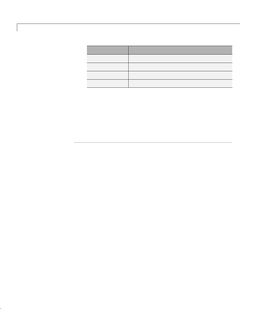
Demo
Generating Structured
Text for a Simple
Simulink Subsystem
Generating Structured
Text for a Hierarchical
Simulink Subsystem
Generating Structured
Text for a Reusable
Simulink Subsystem
Generating Structured
Text for a Stateflow Chart
Generating Structured
Text for an Embedded
MATLAB Block
Description
Demonstrates the code generated for a simple
subsystem co nsisting of basic Simulink blocks.
Demonstrates the code generated for a
hierarchical subsystem consisting of other
Simulink subsystems.
Demonstrates the code generated for a reusable
subsystem co nsisting of basic Simulink blocks.
Demonstrates the code generated for a
Stateflow Chart block.
Demonstrates the code generated for
an Embedded MATLAB Function block
implementing tank valve control logic.
1-5
Page 12

1 Getting Started
Related Products
In this section...
“Requirements for the Simulink®PLC Co de r Product” on page 1-6
“Supported Simulink and Stateflow Blocks” on p age 1-6
“System Requirements” on page 1-7
“Supported IDE Platforms” on page 1-7
Requirements for the Simulink PLC Coder Product
The Simulink PLC Coder product requires current versions of these products:
• MATLAB
• Simulink
The Stateflow product is recommended.
1-6
See the MathWorks Web site at Related Products for a list of related products.
Supported Simulink and Stateflow Blocks
To access a Simulink library of blocks that the Simulink PLC Coder software
supports, type
generate structured text code for subsystems that contain these blocks. The
library window is displayed.
plclib in the MATLAB Command Window. The coder can
Page 13

Related Products
This library contains two sublibraries, Simulink and Stateflow. Each
sublibrary contains the blocks that you can include in a Simulink PLC Coder
model.
See “Block Restrictions” on page 7-4 for restrictions on using these blocks.
System Requirements
Requirement Description
32-bit operating
system
Windows
®
platform supported by The MathWorks
Supported IDE Platforms
The Simulink PLC Coder produ ct supports the following IDE platforms :
• 3S-Smart Software Solutions CoDeSys Version 2.3 or 3.3
1-7
Page 14

1 Getting Started
• Rockwell Automation RSLogix 5000 Series Version 17
• B&R Automation Studio 3.0
• PLCOpen XML
®
• Beckhoff
TwinCAT®2.11
• Generic
3S-Smart Software Solutions CoDeSys Software
To get CoDeSy s Version 2.3 or 3.3, see:
http://www.3s-software.com/index.shtml?en_download
This download page requires you to be a registered user.
1 If you are not yet a registered user, create an account. It might take a few
days to receive a password for the account.
2 When you receive a passwo rd, use it to access the download page.
1-8
3 On the download page, select the CoDeSys software to download.
You do not need to download the CoDeSys SP RTE demo.
4 Follow CoDeSys download and installation instructions to install the
software.
Rockwell Automation RSLogix 5000 Software
To get the Rockwell Automation RSLogix 5000 product, see:
http://www.rockwellautomation.com/rockwellsoftware/design/rslogix5000/
B&R Automation Studio 3.0 Software
To get the B&R Automation Studio product, see:
http://www.br-automation.com/cps/rde/xchg/br-productcatalogue/hs.xsl/cookies_allowed.htm?caller=products_5309_ENG_HTML.htm/
Page 15

Beckhoff TwinCAT 2.11
To get the Beckhoff TwinCAT 2.11 product, see:
http://www.beckhoff.com/english.asp?twincat/default.htm
Related Products
1-9
Page 16

1 Getting Started
Basic Workflow
The basic workflow of Simulink PLC Coder users includes:
1 Define and design a Simulink model from which you want to generate code.
2 Identify the m odel components for which you want to generate code for
downloading to a PLC.
3 Place the compon ents in a Subsystem block.
4 Identify your target PLC IDE.
5 Configure the Subsystem block to be atomic.
6 Check that the model is compatible with the Simulink PLC Coder software.
7 Simulate your model.
8 Configure model parameters to generate code for your PLC IDE.
1-10
9 Examine the generated code.
10 Import code to your PLC IDE.
Page 17

Preparing Your Model to Generate Structured Text Code
Preparing Your M odel to Generate Structured Text Code
In this section...
“Configuring Simulink Models for Structured Text Code Generation” on
page 1-11
“Ensuring System Compatibility for Structured Text Code Generation”
on page 1-16
Configuring Simulink Models for Structured Text
Code Generation
This topic assumes that you have a model for which you want to generate and
import code to a PLC. Before you use this model, perform the following.
1 In the MATLAB Command Window, open your model. For example:
2 Save this model as plcdemo_simple_subsystem1.mdl.
3 Place the components for which you want to generate structured text code
in a subsystem. For example:
1-11
Page 18

1 Getting Started
1-12
Optionally, rename In1 and Out1 to U and Y respectively. This operation
results in a subsystem like the following:
Page 19

Preparing Your Model to Generate Structured Text Code
4 Save the subsystem.
5 In the top-level model, right-click the Subsystem block and select
Subsystem Parameters.
1-13
Page 20

1 Getting Started
1-14
6 In the re
sulting block dialog box, select Treat as atomic unit.
Page 21

Preparing Your Model to Generate Structured Text Code
7 Click OK.
8 Simulate your model.
9 Save
You a
“Ge
your model. In later procedures, you can use either this model, or the
emo_simple_subsystem.mdl
plcd
model that comes with your software.
re now ready to generate structured text code for your IDE. See
nerating and Examining Structured Text Code” on page 1-20.
1-15
Page 22

1 Getting Started
Ensuring System Compatibility for Structured Text
Code Generation
This topic assumes that you have a model that you have prepared to work
with the Simulink PLC Coder software.
1 In your model, navigate to the subsystem for which you want to generate
code.
2 Right-click that Subsystem block and select PLC Coder > Check
Subsystem Compatibility.
1-16
The coder verifies that your model satisfies the Simulink PLC Coder
criteria and displays an information window when done.
Page 23

Preparing Your Model to Generate Structured Text Code
If the subsystem is not atomic, right-clicking the Subsystem block and
selecting PLC Coder prompts you to sele ct Enable “Treat as atomic
unit” to generate code.
1-17
Page 24

1 Getting Started
1-18
This command opens the block parameter dialog box so that you can select
the Treat as atomic unit check box.
Page 25

Preparing Your Model to Generate Structured Text Code
You ar
“Gene
e now ready to generate structured text code for your IDE. See
rating and Examining Structured Text Code” on page 1-20.
1-19
Page 26

1 Getting Started
Generating and Examining Structured Text Code
In this section...
“Generating Structured Text Code from the Model Window” on page 1-20
“Generating Structured Text Code with the MATLAB Interface” on page
1-25
Generating Structured Text Code from the Model
Window
This topic assumes that you have set up your environment and Simulink
modeltousetheSimulinkPLCCodersoftwaretogeneratestructuredtext
code. If you have not yet done so, see “Preparing Your Model to Generate
Structured Text Code” on page 1-11.
1 If you do not have the plcdemo_simpl e_subsystem model open, open it now.
2 Right-click the Subsystem block and select PLC Coder > Options.
1-20
Page 27

Generating and Examining Structured Text Code
The Conf
iguration Parameters dialog box is displayed.
1-21
Page 28

1 Getting Started
3 In PLC Coder > General options > Target IDE, select a target IDE.
For example, select
CoDeSys 2.3.
1-22
4 Click Apply.
5 Click the Generate code button.
This button:
• Generates structured text code (same as the PLC Coder > Generate
Code for Subsystem option)
• Stores generated code in
plcdemo_simple_subsystem.exp)
model_name.exp (for ex ample,
When code generation is complete, an information window is displayed.
Page 29

Generating and Examining Structured Text Code
This window has links that you can click to open the associated files.
The Simulink PLC Coder software generates structured text code and stores
it depending on the target IDE platform.
Platform
Generated Files
CoDeSys IDE current_folder\plcsrc\model_name.exp — Structured text file
appropriate for downloading to the target IDE.
Rockwell Automation
RSLogix 5000 IDE
current_folder\plcsrc\plcdemo_simple_subsystem.L5X
(model_name.L5X). — Structured text file appropriate for downloading
to the target IDE. This file is in XML format and contains the
generated structured text code for your model.
1-23
Page 30

1 Getting Started
Platform
B&R Automation
Studio IDE
Generated Files
Five or six files in folder
current_folder\plcsrc\model_name\subsystem — Files appropriate
for downloading to the target IDE. Note that the
subsystem folder
name might be truncated.
•
IEC.lby
Main project definition file in XML format.
subsystem_block_name.fun
•
Text file. Function block interface definitions file. The coder
generates one file per project.
•
subsystem_block_name.st
Text file. Structured text f unction body files. The coder generates
one file per function block in the generated code.
•
subsystem_block_name.typ
Text file. Structure and enumerated type definitions file. The coder
generates one file per project.
•
subsystem_block_name.var
Text file. Global constant definitions file. The coder generates one
file per project.
PLCOpen XML
Beckhoff TwinCAT
2.11
Generic
1-24
•
TestBench.st (If test bench is generated.)
Text file. structured text file for generated test bench code.
current_folder\plcsrc\plcdemo_simple_subsystem.xml
(model_name.xml) — Structured text file formatted using the
PLCOpen XML standard.
current_folder\plcsrc\plcdemo_simple_subsystem.exp
(model_name.exp). — Structured text file appropriate for downloading
to the target IDE.
current_folder\plcsrc\plcdemo_simple_subsystem.st
(model_name.st) — Pure structured text file. If your target ID E is not
available for the Simulink PLC Coder product, consider generating
and downloading a generic structured text file.
Page 31

Generating and Examining Structured Text Code
The example in this topic illustrates generated code for the C oD eSys
Version 2.3 PLC IDE. Generated code for other platforms, such as Rockwell
Automation RSLogix 5000, i s in XML form at and looks different.
After generating structured text code, examine it to ensure that it is what you
expect. See Chapter 2, “Mapping Simulink Semantics to Structured Text” for
a d escription of h ow the generated code for the Simulink components map to
structured text components.
Generating Structured Text Code with the MATLAB
Interface
You can generate structured text code for a subsystem from the MATLAB
Command Window with the
assumes that you have configured the parameters for the model, or that you
plcgeneratecode function. The function
1-25
Page 32

1 Getting Started
want to use the default settings. For example, to open the Configuration
Parameters dialog box for the subsystem, type:
plcopenconfigset('plcdemo_simple_subsystem/Simple_Subsystem')
Configure the subsystem as described in “Generating Structured Text Code
from the Model Window” on page 1-20.
To generate the code for the subsystem, type:
generatedfiles = plcgeneratecode('plcdem o_simple_subsystem/Simple_Subsystem')
1-26
Page 33

Mapping Simulink
Semantics to Structured
Text
When you examine generated code, you evaluate how well the Simulink PLC
Coder software has generated code from your model. The following topics
describe how the coder maps Simulink subsystem semantics to function block
semantics in structured text. As examples, the topics describe the m apping
in the context of the different subsystem types that Simulink supports. The
examples assume that you have already generated code (see “Generating
Structured Tex t Code from the Model Window” on page 1-20). All demos are
located in the
matlabroot\toolbox\plccoder\plccoderdemos folder.
2
These topics use code generated with CoDeSys Version 2.3.
• “How Simple Subsystem Code Maps to Function Blocks” on page 2-2
• “How Reusable Subs ystem Code Maps to Function Blocks” on page 2-4
• “How Stateflow Subsystem Code Maps to Function Blocks” on page 2-6
• “How Embedded MATLAB Subsystem Code Maps to Function Blocks”
on page 2-8
• “How Alias Data Types Map in Generated Code” on page 2-10
Page 34

2 Mapping Simulink
®
Semantics to Structured Text
How Simple Subsystem Code Maps to Function Blocks
This topic assumes that you have generated structured text code from a
Simulink model. If you have not yet done so, see “Generating Structured Text
Code from the Model Window” on page 1-20.
The example in this topic shows generated code for the CoDeSys Version 2.3
PLC IDE. Generated code for other IDE platforms looks different.
1 If you do not have the plcdemo_simple_subsystem.exp file open, open it
now in the MATLAB editor. Type the following in the folder that contains
the file:
edit plcdemo_simple_subsystem.exp
A file like the following is displayed.
This figure illustrates the mapping of the generated code for a simple
Simulink subsystem to structured text components. The Simulink
subsystem corresponds to the structured text function block,
Subsystem.
2-2
Page 35

How Simple Subsystem Code Maps to Function Blocks
Input parameter for
subsystem method
type
Subsystem
inputs and
outputs
Subsystem
State (DWork)
variables
Initialize, output,
and update
methods
Atomic subsystem name
Inlined
parameters
Subsystem
2 Inspect this code as you ordinarily do for PLC code. Ensure that the
generatedcodeisasyouexpect.
2-3
Page 36

2 Mapping Simulink
®
Semantics to Structured Text
How Reusable Subsystem Code Maps to Function Blocks
This topic assumes that you have generated structured text code from a
Simulink model. If you have not yet done so, see “Generating Structured Text
Code from the Model Window” on page 1-20.
The example in this topic shows generated code for the CoDeSys Version 2.3
PLC IDE. Generated code for other IDE platforms looks different.
1 Open the plcdemo_reusable_subsystem model.
2 Right-click the Subsystem block and select PLC Coder > Generate Code
for Subsystem.
The Simulin
places it i
3 If you do not have the plcdemo_reusable_subsystem .ex p file open, open it
k PLC C oder software generates structured tex t code and
n
current_folder/plcsrc/plcdemo_reusable_subsystem.exp.
now in the MATLAB editor.
This figure illustrates the mapping of the generated code for a reusable
Simulink subsystem to structured text components. This graphic contains
a copy of the hierarchical subsystem, ReusableSubsystem. This subsystem
contains two identical subsystems, S1 and S2. This configuration enables
code reuse between the two instances (look for the
ReusableSubysstem
string in the code).
2-4
Page 37

How Reusable Subsystem Code Maps to Function Blocks
Instance variables
Instance invocations (call sites)
Reused code in
FUNCTION_BLOCK
4 Examine the generated structured text code. The code define s
FUNCTION_BLOCK S0_S1 once.
5 Look for two instance variables that correspond to the two instances
declared inside the parent
S0_S1
instances separately by passing in different inputs. The code invokes the
outputs p er the Simulink execution semantics.
FUNCTION_BLOCK S0 (_instance_S0_S1_1:
and _instance_S0_S1_0: S0_S1). The code invokes these two
2-5
Page 38

2 Mapping Simulink
®
Semantics to Structured Text
How Stateflow Subsystem Code Maps to Function Blocks
This topic assumes that you have generated structured text code from a
Simulink model. If you have not yet done so, see “Generating Structured Text
Code from the Model Window” on page 1-20.
The example in this topic shows generated code for the CoDeSys Version 2.3
PLC IDE. Generated code for other IDE platforms looks different.
1 Open the plcdemo_stateflow_controller model.
2 Right-click the ControlModule chart and select PLC Coder > Generate
Code for Subsystem.
The Simulink PLC Coder software generates structured text code and p laces
it in
current_folder/plcsrc/plcdemo_stateflow_controller.exp.
3 If you do not have the plcdemo_stateflow_controller.exp file open,
open it now in the MATLAB editor.
2-6
This figure illustrates the mapping of the generated code for a Simulink
Subsystem block that contains a Stateflow chart to structured text
components.
Page 39

How Stateflow®Subsystem Code Maps to Function Blocks
Inlined code for Stateflow chart
4 Examine the gene rate d structured text code.
The Simulink PLC Coder software aggressively inlines the generated code
for the Stateflow chart. The coder performs this inlining because different
functions from S tateflow charts share some global state data. However,
function blocks in structured text code do not share state data. As a result,
the coder software cannot map these functions onto separate function blocks.
Instead, it must inline these functions.
2-7
Page 40

2 Mapping Simulink
®
Semantics to Structured Text
How Embedded M ATLAB Subsystem Code Maps to
Function Blocks
This topic assu
Simulink model
Code from the M
The example in
PLC IDE. Gene
1 Open the plcd
2 Right-click the TankControl block and select PLC Coder > Generate
Code for Subsystem.
The Simulink P LC Coder software generates structured text code and
places it in
3 If you do n
now in the
This figure illustrates the mapping of the generated code for a Simulink
Subsystem block that contains an Embedded MATLAB Function block to
structured text components. The coder tries to perform inline optim iza t ion
on the generated code for Embedded MATLAB subfunctions. If the coder
determines that it is more efficient to leave the subfunction as is, it
places the generated code in a structured text construct called
Themaindifferencebetweena
FUNCTION cannot have states and cannot access global variables.
mes that you have generated structured text code from a
. If you have not yet done so, see “Generating Structured Text
odel Window” on page 1-20.
this topic shows generated code for the CoDeSys Version 2.3
rated code for other IDE platforms looks different.
emo_eml_tankcontrol
current_folder/plcsrc/plcdemo_eml_tankcontrol.exp.
ot have the
MATLAB editor.
plcdemo_eml_tankcontrol.exp file open, open it
model.
FUNCTION.
FUNCTION_BLOCK and FUNCTION is that a
2-8
Page 41

Embedded MATLAB code
How Embedded MATLAB®Subsystem Code Maps to Function Blocks
Generated
Embedded MATLAB
function code
4 Examine the gene rate d structured text code.
2-9
Page 42

2 Mapping Simulink
®
Semantics to Structured Text
How Alias Data Types Map in Generated Code
The coder maps alias data types to the base data type in the generated code.
2-10
Page 43

Generating Test Bench
Code
3
Page 44

3 Generating Test Bench Code
Working with Generated Structured Text
In this section...
“How Test Bench Verification Works” on page 3-2
“Generating a nd Importing Structured Text” on page 3-2
“Generated Files” on page 3-4
How Test Bench Verification Works
The Sim ulink PLC Coder software simulates your model and automatically
captures the input and output signals for the subsystem that contains your
algorithm. This set of input and output signal data is the test bench data.
The coder also automatically generates a test bench (test harness) using
the text bench data. The test bench verifies that the generated code is
functionally and numerically equivalent to the Simulink model. To perform
this verification, import the generated structured text and the test bench data
into your target IDE.
3-2
Generating and Importing Structured Text
This topic describes the basic procedure for how to generate test bench code.
It uses the CoDeSys environment as an example target IDE.
This topic assumes that you have an appropriately configured model from
which to generate structured text. If you have not yet done this procedure,
see “Preparing Your Model to Generate Structured Text Code” on page 1-11.
All dem os are located in the
folder.
1 If you do not have the plcdemo_simpl e_subsystem model open, open it now.
2 Ensure that you have connected the inputs and outputs of the subsystem
for which you want to generate the test bench. You can import this test
bench with the generated code to the target IDE to verify simulation results
with Simulink output. For example:
matlabroot\toolbox\plccoder\plccoderdemos
Page 45

Working with Generated Structured Text
3 Right-click the Subsystem block and select PLC Coder > Options.
The Con
4 In PLC Coder > General options > Target ID E, select your target IDE,
for example,
5 Select the Generate testbench for subsystem check box.
6 Click
7 Click the Generate code button.
figuration Parameters dialog box is displayed.
CoDeSys 2.3.
Apply.
This button:
• Generates structured text code (same as the PLC Coder > Generate
Code for Subsystem option)
• Generates test bench for code through Simulink simulation
3-3
Page 46

3 Generating Test Bench Code
• Combines generated code and test bench into m odel_name.exp (for
example,
When the code generation is complete, an information window is displayed.
plcdemo_simple_subsystem.exp).
3-4
8 Click OK.
The Simulink P LC Coder software generates structured text code and
writes it to
Depending on the target IDE, the coder might generate additional
supporting files.
9 See the user manual for your target IDE for information on how to import
generated code into the target IDE.
current_folder/plcsrc/plcdemo_simple_subsystem.
Generated Files
Depending on the target IDE platform, the Simulink PLC Coder software
generates code into one or more files. See “Generating Structured Text Code
Page 47

Working with Generated Structured Text
from the Model Window” on page 1-20 for list of the target IDE platforms and
the possible generated files.
3-5
Page 48

3 Generating Test Bench Code
3-6
Page 49

4
Working with Tunable
Parameters in the Simulink
PLC Coder Environment
Page 50

4 Working with Tunable Parameters in the Simulink
®
PLC Coder™ Environment
Configuring Tunable Parameters for Your Model
In this section...
“About Tunable Parameters in the Simulink®PLC Coder Environment”
on page 4-2
“Workflow Overview” on page 4-2
“Identifying Tunable Parameters” on page 4-3
“Defining Tunable Parameters in the MATLAB Workspace” on page 4-5
“Configuring Parameters to Be Tuna ble” on page 4-8
“Tunable Parameters Considerations” on page 4-12
About Tunable Parameters in the Simulink PLC Coder
Environment
Dialog parameters can be either tunable or nontunable. A tunable parameter
is a parameter that you can change while the simulation is running. The
Simulink PLC Coder software allows you to tune parameters:
4-2
• From the MATLAB workspace, while the model simulation is running
• In the ID E, while the generated code is running
Workflow Overview
This topic describes how to configure your model to enable tunable parameters.
By default, Simulink PLC Coder parameters are inlined and not tunable.
The general workflow for configuring a model to enable tunable parameters is:
1 Identify the model parameters yo u want to be tunable.
2 Define these parameters in the MATLAB workspace.
3 Configure tunable parameters in the Configuration
Parameters > O ptimization > Model Parame ter Config ur atio n
dialog box.
Page 51

Configuring Tunable Parameters for Your Model
Identifying Tunable Parameters
This topic creates the model my_plcdemo_tunable _par ams to show
how to configure tunable parameters. This model is the same as the
plcdemo_tunable_params model. Thedifferenceisthatthedemomodel
already has the tunable parameters configured, while this topic guides you in
configuring the tunable parameters.
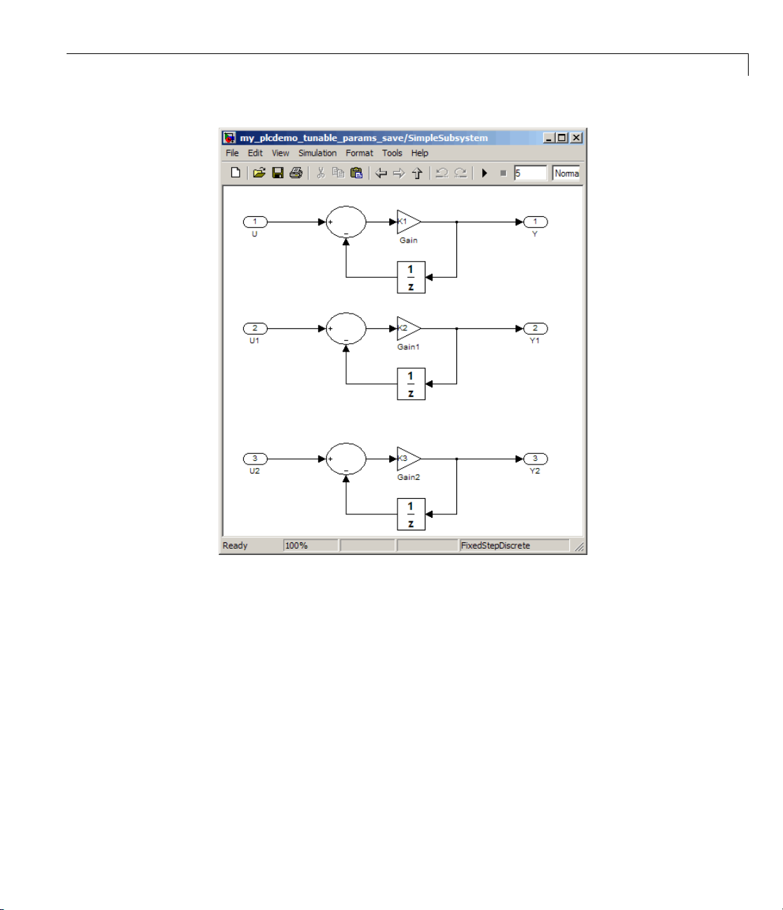
1 IntheMATLABCommandWindow,createamodeltolooklikethe
following:
ct the Sum, Gain, and Unit Delay blocks and create an atomic
2 Sele
ystem with inputs U, U1, and U2 and outputs Y, Y1, and Y2. Rename
subs
ubsystem block as SimpleSubystem. When you are finished, the top
the S
l and atomic subsystem model should look like the following:
mode
4-3
Page 52

4 Working with Tunable Parameters in the Simulink
®
PLC Coder™ Environment
4-4
3 Save this subsystem as my_plcdemo_tunable_params.mdl.
4 Double-click SimpleSubsystem.
Page 53
Configuring Tunable Parameters for Your Model
5 Note the three Gain blocks that have the constants that you want to make
tunable: K1, K2,andK3.
Next, define these parameters in the MATLAB workspace. See “Defining
Tunable Parameters in the MATLAB Workspace” on page 4-5.
Defining Tunable Parameters in the MATLAB
Workspace
This topic describes h ow to define tunable parameters in the MATLAB
workspace using the Simulink Model Properties dialog box. Defining tunable
parameters in this way ensures that the model automatically defines the
parameters each time you open the model.
4-5
Page 54
4 Working with Tunable Parameters in the Simulink
It assumes that you created the my_plcdemo_tunable_params model or
opened
youhavenotyetdoneso,see“IdentifyingTunableParameters”onpage4-3.
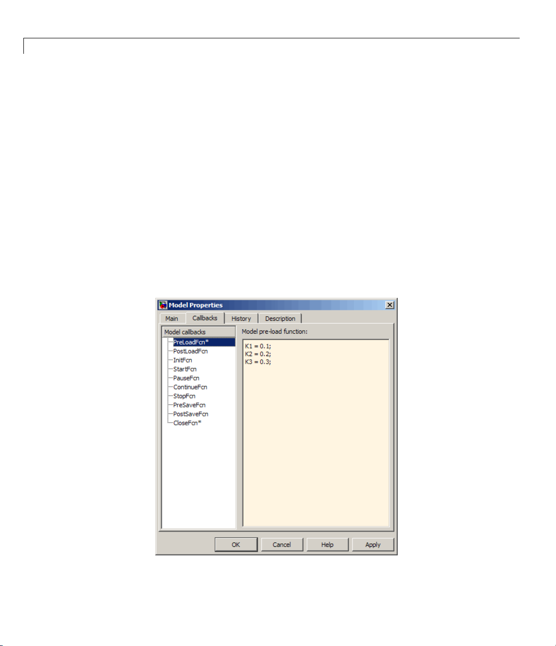
1 In the my_plcdemo_tunable_params model, select File > Model
2 In the Callbacks pane, select PreLoadFcn.
3 In the Model pre-load function pane, enter the three constants K1, K2,
plcdemo_tunable_params and identified the parameters for tuning. If
Properties.
The Model Properties dialog box is displayed.
and K3. Assign initial values to them. For example:
K1 = 0.1;
K2 = 0.2;
K3 = 0.3;
®
PLC Coder™ Environment
4-6
Page 55

Configuring Tunable Parameters for Your Model
4 Click Apply.
5 In the Callbacks pane, select CloseFcn.
6 In the Model close function pane, enter the clear command to clear
these constants. For example:
clear K1 K2 K3;
This command ensures that you clear the se constants from the MATLAB
workspace when you close the model.
7 Click Apply,thenOK.
Your next task is to configure these parameters to be tunable. See
“Configuring Parameters to Be Tunable” on page 4-8.
4-7
Page 56

4 Working with Tunable Parameters in the Simulink
Configuring Param eters to Be Tunable
This topic describes how to configure parameters to be tunable using the
Simulink Configuration Parameters dialog box.
®
PLC Coder™ Environment
It assumes that you created the
opened
plcdemo_tunable_params and defined the parameters for tuning. If
my_plcdemo_tunable_params model or
you have not yet done so, see “Defining Tunable Parameters in the MATLAB
Workspace” on page 4-5.
This topic uses code generated with CoDeSys Version 2.3.
1 In the model, right-click SimpleSubsystem and select PLC
Coder > Options.
2 Navigate to the Optimization node.
3 In the Simulation and code generation section of the Optimization
pane, ensure that the Inline parameters check box is selecte d. (This
check box is selected by default.)
4 In this section, click Configure.
4-8
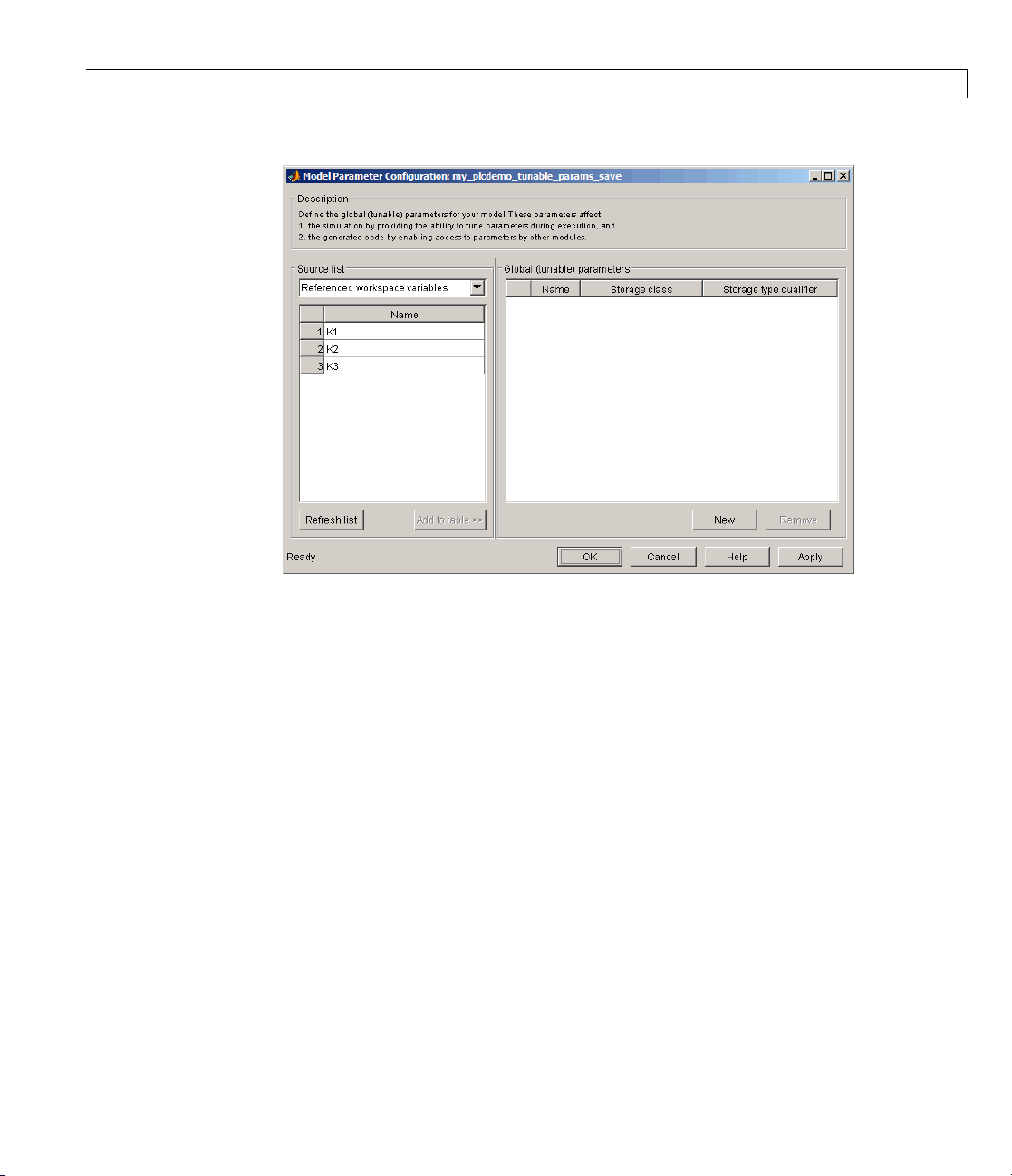
The Model Parameter Configuration dialog box is displayed.
Page 57
Configuring Tunable Parameters for Your Model
5 From Source list, select Referenced workspace variables.
6 Use the Ctrl key to select all the parameters and click Add to table >> to
add them to the Global (tunable) parameters table.
4-9
Page 58

4 Working with Tunable Parameters in the Simulink
®
PLC Coder™ Environment
4-10
By default, this dialog box sets all parameters to the SimulinkGlobal
(Auto)
storage class. This setting generates code with the tunable
parameters set at the local level. In this case, these parameters appear at
the function block level in each function block that uses the parameter.
You can also optionally set the storage type qualifier for a parameter to
const.
7 Click Apply and OK.
8 In the Configuration Parameters dialog box, navigate to PLC
Coder > General options.
9 Ensure that Target IDE and Output Directory settings are appropriate,
then click Generate Code.
10 Observe that the VAR section of Function Block SimpleSubsystem defines
K1, K2,andK3.
Page 59

Configuring Tunable Parameters for Your Model
11 Toconfigureaparametertobeaglobalvariableinthegeneratedcode,set
the parameter storage class of K2 to
ExportedGlobal. Leave the storage
type qualifier unset.
Some ta
suppor
softw
rget IDEs, such as the Rockwell Automation RSLogix IDE, do not
t the access of global variables. In this case, the Simulink PLC Coder
are uses
SimulinkGlobal as the automatic storage class.
Toconfigureaparametertobeaglobalconstant in the generated code, set
the parameter storage class of K3 to
qualifier to
12 Click Apply and OK, then rebuild the code.
13 Obs
erve that K2 is now in the
_GLOBAL_CONSTANT
VAR
const.
section.
ExportedGlobal. Set storage type
VAR_GLOBAL section. K3 is in the
4-11
Page 60

4 Working with Tunable Parameters in the Simulink
14 To configure a parameter so that you or somebody else can provide it
through external structured text, set the parameter storage class of K1 to
ImportedExtern. The coder does not generate a variable declaration for
theparameterinthecode. Leavethestoragetypequalifierunset.
15 Click Apply and OK, then rebuild the code.
16 Observe that K1 no longer appears in the VAR section of the generated code.
®
PLC Coder™ Environment
4-12
Note The Simulink PLC Coder software does not support the setting of
the parameter storage class to
parameter to this value, the software treats it the same as
ImportedExternPointer.Ifyousetthe
ImportedExtern.
Tunable Parameters Considerations
When tuning parameters, the coder does not support:
• Specifying parameters using
tunable parameters instead.
• Tuning parameters of bus data type.
Simulink.Parameter object. Use global
Page 61

5
Controlling Generated Code
Partitions
Page 62

5 Controlling Generated Code Partitions
Function Block Partitions
In this section...
“About Function Block Partitions” on page 5-2
“Example: One Function Block for Atomic Subsystems” on page 5-2
“Example: One Function Block for Virtual Subsystems” on page 5-3
“Example: Multiple Function Blocks for Nonvirtual Subsystems” on page
5-4
“Controlling Generated Code Using Subsystem Block Parameters” on page
5-5
About Function Block Partitions
The Simulink PLC Coder software converts subsystems to function block
units, one subsystem per function block. You control generated code
partitioning by the number and types of Subsystem blocks that you have in
your model. The coder generates structured text function blocks as follows:
5-2
• Generates one function block for an atomic subsystem that contains no
other subsystems.
• Generates one function block for an atomic subsystem that contains only
virtual subsystems. For virtual subsystems, the Simulink PLC Coder
software generates code that is indistinguishable from the rest of the
contents of the atomic subsystem. It generates code that is flattened.
• Generates a function block for each nonvirtual subsystem contained in
an atomic subsystem . Nonvirtual subsystems can be atomic, fcn-call,
or enabled. You can customize this partitioning with the Real-Time
Workshop system code parameter of the Subsystem block.
These topic use code generated with CoDeSys Version 2.3.
Example: One Function Block for Atomic Subsystems
Thecodefortheplcdemo_simple_subsystem demo is an example of
generating code with one function block. The atomic subsystem for which you
generate code does not contain any other subsystems.
Page 63

Function Block Partitions
Example: One Function Block for Virtual Subsystems
The plcdem o_hi erarchical_virtual_subsystem demo contains an atomic
subsystem that has two virtual subsystems, S1 and S2, inlined. A virtual
subsystem does not have the Treat as atomic unit parameter selected.
Whenyougeneratecodeforthehierarchicalsubsystem,thecodecontains
only the
additional function blocks for the S1 and S2 subsystems.
FUNCTION_BLOCK HierarchicalSubsystem component. There are no
5-3
Page 64

5 Controlling Generated Code Partitions
5-4
Example: Multiple Function Blocks for Nonvirtual
Subsystems
The plcdemo_hierarchical_subsystem demo contains an atomic subsystem
that has two nonvirtual subsystems, S1 and S2. Virtual subsystems have
the Treat as atomic unit parameter selected. When you generate code
for the hierarchical subsystem, that code contains the
HierarchicalSubsystem
and
FUNCTION_BLOCK HierarchicalSubsystem_S2 components.
, FUNCTION_BLOCK HierarchicalSubsystem_S1,
FUNCTION_BLOCK
Page 65
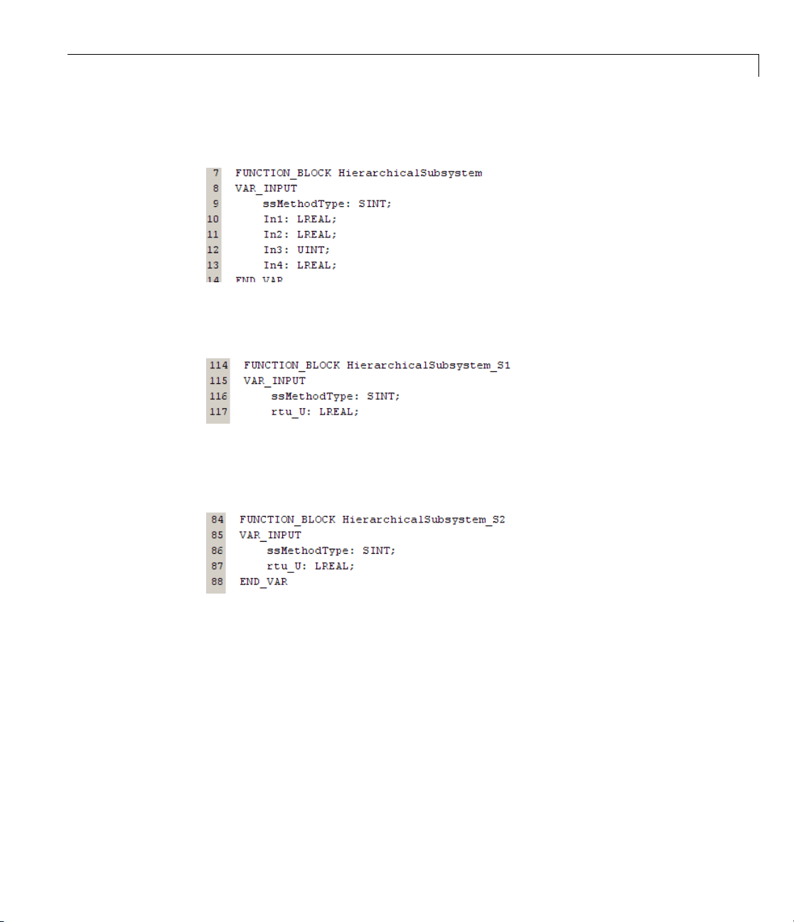
Function Block for Hierarchical Subsystem
Function Block for Hierarchical S1
Function Block Partitions
Function Block for Hierarchical S2
Controlling Generated Code Using Subsystem Block
Parameters
You can partition generated code us ing the following Subsystem block
parameters:
• Real-Time Workshop system code
• Real-Time Workshop function name options
Leave the Real-Time Workshop file name options set to the default,
Auto.
5-5
Page 66

5 Controlling Generated Code Partitions
Generating Separate Partitions and Inlining Subsystem Code
Use the Real-Time Workshop system code parameter to specify the code
format to generate for an atomic (nonvirtual) subsystem. The Simulink PLC
Coder software interprets this parameter:
If Real-Time Workshop system
code is
Auto,
Reusable function, Function
Inline
For example, in the plcdemo_hierarchical_virtual_subsystem,youcan:
• Inline the S1 subsystem code by setting Real-Time Workshop system
code to
the S1 subsystem inlined.
• Create a function block for the S2 subsystem by setting Real-Time
Workshop system code to
setting creates two function blocks, one for the parent, one for S2.
Inline. This setting creates one function block for the parent w ith
Reusable function, Auto,orFunction.This
Coder Interpretation
Chooses the optimal format based
on the type and number of instances
of the subsystem that exist in the
model.
Generates a function with arguments
that allows the subsystem code to be
shared by other instances of it in the
model.
Inlines the subsystem
unconditionally.
5-6
Page 67

Function Block Partitions
Changing the Name of a Subsystem
You can use the Real-Time Workshop function n am e options parameter
to change the name of a subsystem from the one on the block label. When
the Simulink PLC Coder software generates software, it uses the string
you specify for this parameter as the subsystem name. For example, in the
plcdemo_hierarchical_virtual_subsystem demo:
1 Open the S1 subsystem block parameter dialog box.
2 Set Real-Time Workshop system code to Function.
3 Set Real-Time Workshop function name options to User specified.
4 In the Real-Time Workshop function name field, specify a custom
name. For example, type
my_own_subsystem.
5-7
Page 68

5 Controlling Generated Code Partitions
5-8
5 Save the new settings.
6 Generate code for the parent subsystem.
7 Observe the renamed function block.
Page 69

6
IDE-Specific Considerations
Page 70

6 ID E-Specific Considerations
Introduction
This chapter describes IDE-specific considerations you should be aware of
when generating and downloading code.
Considerations for All Target IDEs
The coder converts matrix data types to single-dimensional vectors
(column-major) in the generated structured text.
Rockwell Automation RSLogix Considerations
This topic d escribes the considerations to remember for this target IDE
platform.
In this section...
“Considerations for All Target IDEs” on page 6-2
“Rockwell Automation RSLogix Considerations” on page 6-2
6-2
Add-On Instruction and Function Blocks
The structured text concept of function block exists for Rockwell Automation
RSLogix target IDEs as an Add-On instruction (AOI). The Simulink PLC
Coder software generates AOIs for this target, not FUNCTION_BLOCK.
Double-Precision Data Types
The Rockwell Automation RSLogix target IDE d oe s not support
double-precision data types. At code generation, the Simulink PLC Coder
converts this data type to single-precision data types in generated code.
Note Design your model to use single-precision data type (single) as much
as possible instead of double-precision data type (double). If you must use
doubles in your model, note that the numerical results produced by the
generated structured text might differ from Simulink results. This difference
isduetodouble-singleconversion during code generation.
Page 71

Introduction
Unsigned Integer Data Types
The Rockwell Automation RSLogix target IDE does not support unsigned
integer data types. At code generation, the Simulink PLC Coder converts this
data type to signed integer data types in generated code.
Note Design your model to use signed integer data types (int8, int16, int32)
as much as possible instead of unsigned integer data types (uint8, uint16,
uint32). D oing so avoids overflow issues that unsigned-to-signed integer
conversions can cause at code generatio n.
Enumerated Data Types
The Rockwell Automation RSLogix target IDE does not support enumerated
data types. At code generation, the Simulink PLC Coder converts this data
type to 32–bit signed integer data types in generated code.
6-3
Page 72

6 ID E-Specific Considerations
6-4
Page 73

Limitations
• “Coder Limitations” on page 7-2
• “Block Restrictions” on page 7-4
7
Page 74

7 Limita tions
Coder Limitations
In this section...
“Current Limitations” on page 7-2
“Permanent Limitations” on page 7-2
Current Limitations
The Simulink PLC Coder softw are does not support the following Simulink
semantics:
• Fixed-point data types
• Complex data types
• Model reference
• Global data store memory (DSM)
• Absolute time temporal logic in Stateflow charts
7-2
• Stateflow machine-parented data and events
• Exported graphical functions in Stateflow charts
• Limited support for math functions. The coder does not support the
following functions:
• Triggered subsystems
• Merge block
• Multi-rate mode ls
• Signal and state storage classes
tanh, cosh, sinh, atan2, rand.
Permanent Limitations
The structured text language has inherent restrictions. As a result, the
Simulink PLC Coder software has the following restrictions:
• The Simulink PLC Coder software supports generating code only for
atomic subsystems.
• The solver type for the Simulink model must be fixed-step and discrete.
Page 75

Coder Limitations
• No blocks that require continuous time semantics. This restriction includes
continuous integrators, zero-crossing blocks, physical modeling blocks,
and so on.
• No pointer data types.
• No recursion (including recursive events).
7-3
Page 76

7 Limita tions
Block Restrictions
In this section...
“Simulink Block Support Exceptions” on page 7-4
“Stateflow Chart Exceptions” on page 7-4
Simulink Block Support Exceptions
The Simulink PLC Coder software supports the plclib blocks with the
following exceptions. Also, see Chapter 7, “Limitations” for a list of limitations
of the software.
If you get unsupported fixed-point type error messages during code
generation, update the block parameter. Open the block param eter dialog
box. Navigate to the Signal Attributes and Parameter Attributes tabs.
Ensure that the Output data type and Parameter data type parameters
are not
either
type, such as
Inherit: Inherit via internal rule. Set these parameters to
Inherit: Same as input or an appropriate non-fixed-point data
double or int8.
7-4
Stateflow Chart Exceptions
If you receive an error like t he following during code generation and the model
contains a Stateflow chart that contains one or more Simulink functions, use
thefollowingproceduretoaddresstheissue:
The 'State when enabling' parameter of the Trigger Port
block inside the Function-Call subsystem
'msimpleslFcn/Subsystem/Chart/slFcn' is set to 'inherit'.
Simulink cannot ensure con sistency between the origi nal
subsystem 'msimpleslFcn/Subsystem' and the S-function
generated from subsystem b uild. The 'Stat e when enabling'
parameter must be set to 'reset' or 'held'.
1 Open the model and double-click the Stateflow chart that is causing the
issue.
The chart Statef low Editor dialog box is displayed.
Page 77

Block Restrictions
2 Right-click in this dialog box.
3 In the context-sensitive menu, select Properties.
The Chart dialog box is displayed.
4 In the C hart dialog box, navigate to the States When Enabling parameter
and select
5 Click Apply and OK and save the model.
Held.
7-5
Page 78

7 Limita tions
7-6
Page 79

Functions — Alphabetical
List
8
Page 80

plccoderdemos
Purpose Product demos
Syntax plccoderdemos
Description plccoderdemos displays the Simulink PLC Co der demos in the
MATLAB Help browser.
Example Display demos in the MATLAB Help browser.
plccoderdemos
See Also plcopenconfigset
8-2
Page 81

plccoderpref
Purpose Set target IDE
Syntax plccoderpref
plccoderpref('plctargetide')
plccoderpref('plctargetide', IDEcodename)
plccoderpref('plctargetide', 'default')
Description plccoderpref displays the current set of user preferences, including
the default target IDE.
plccoderpref('plctargetide') returns the current default target
IDE. This default can be the target IDE set previoiusly, or the factory
default. The factory default is
plccoderpref('plctargetide', IDEcodename) sets the default target
IDEtotheonethatyouspecifyin
that IDEcodename persists as the default target IDE for all future
MATLAB sessions.
plccoderpref('plctargetide', 'default') sets the default target
IDE to the factory default target IDE (
'codesys23'.
IDEcodename. This command ensures
'codesys23').
Input
Arguments
'plctargetide'
String directive that specifies the default target IDE.
'IDEcodename'
String that specifies the default target IDE. String must be one of:
Name
codesys23
codesys33
rslogix5000
Description
3S-Smart Software Solutions CoDeSys
Version 2.3 (default) target IDE
3S-Smart Software Solutions CoDeSys
Version 3.3 target IDE
Rockwell Automation RSLogix 5000 Series
target IDE
8-3
Page 82
plccoderpref
Name
brautomation30
plcopen
twincat211
generic
'default'
Description
B&R Automation Studio 3.0 target IDE
PLCOpen XML target IDE
Beckhoff TwinCA T 2.11 target IDE
Generic target IDE
String directive that sets 'plctargetide' to factory default
(
'codesys23').
Example Return the current default target IDE.
plccoderpref('plctargetide')
Set rslogix5000 as the new default target IDE.
plccoderpref('plctargetide', 'rslogix5000')
8-4
Page 83

plcgeneratecode
Purpose Generate structured text for subsystem
Syntax generatedfiles = plcgeneratecode(subsystem)
Description generatedfiles = plcgeneratecode(subsystem) generates
structured text for the specified atomic subsystem in a model.
subsystem is the fully qualified path name of the atomic subsystem.
generatedfiles is a cell array of the generated file names.
Example Generate code for the subsystem,
plcdemo_simple_subsystem/Simple_Subsystem.
generatedfiles = plcgeneratecode('plcdemo_simple_subsystem/Simple_Subsystem')
See Also plcopenconfigset
8-5
Page 84

plcopenconfigset
Purpose Open Configuration Parameters dialog box for subsystem
Syntax plcopenconfigset(subsystem)
Description plcopenconfigset(subsystem) opens the Configuration Parameters
dialog box for the specified atomic subsystem in the model. subsystem is
the fully qualified path name of the atomic subsystem.
Example Open the Configuration Paramete rs dialog box for the subsystem,
plcdemo_simple_subsystem/Simple_Subsystem.
plcopenconfigset('plcdemo_simple_subsystem/Simple_Subsystem')
See Also plcgeneratecode
8-6
Page 85

Configuration Parameters
for Simulink PLC Coder
Models
• “PLC Coder: General” on page 9-2
• “PLC Coder: Comments” on page 9-8
• “PLC Coder: Symbols” on page 9-12
9
Page 86

9 Configuration Parameters for Simulink
PLC Coder: General
In this section...
®
PLC Coder™ Models
9-2
“PLC Overview” on page 9-3
“TargetIDE”onpage9-4
“Output directory ” on page 9-6
“Generate testbench for subsystem” on page 9-7
Page 87

PLC Coder: General
PLC Overview
Set up general information about generating structured text code to download
to target PLC IDEs.
Configuration
This pane appears only if your model contains an atomic Subsystem block.
To enable the Simulink PLC Coder options pane, you must:
1 Create a model.
2 Add either an Atomic Subsystem block, or a Subsystem block for which you
have selected the Treat as atomic unit check box.
3 Right-cli
Tip
In additi
can also u
code for t
on to configuring parameters for the Simulink PLC Coder model, you
See Also
“Gener
ating Structured Text Code from the Model Window” on page 1-20
ck the subsystem block and select PLC Coder > Options.
se this dialog box to generate structured text code and test bench
he Subsystem block.
9-3
Page 88

9 Configuration Parameters for Simulink
Target IDE
Select the target language in which to generate code.
Settings
Default: Structured Text (CoDeSys)
CoDeSys 2.3
Generates structured text (IEC 61131) code for 3S-Smart Software
Solutions CoDeSys software Version 2.3.
CoDeSys 3.3
Generates structured text (IEC 61131) code for 3S-Smart Software
Solutions CoDeSys software Version 3.3.
RSLogix 5000
Generates structured text code for Rockwell Automation RSLogix 5000
software.
B&R Automation Studio 3 .0
Generates structured text code for B&R Automation S tudio 3.0 software.
®
PLC Coder™ Models
9-4
PLCOpen XML
Generates structured text code formatted using PLCOpen XML
standard.
Beckhoff TwinCAT 2.11
Generates structured text code fir Beckhoff TwinCAT 2.11 software.
Generic
Generates a pure structured text file. If your desired target IDE is not
available for the Simulink PLC Coder product, consider generating and
downloading a generic structured text file.
Tip
• Start each reserved name with a letter or an underscore to prevent error
messages.
• Each reserved name must contain only letters, numbers, or underscores.
• Separate the reserved names using commas or spaces.
Page 89

PLC Coder: General
Command-Line Information
Parameter: PL C_TargetIDE
Type: string
Value:
'brautomation30' | 'plcopen' | 'twincat211' | 'generic'
Default: 'codesys23'
'codesys23' | 'c odesys33' | 'rslogix5000' |
See Also
“Generating S tructured Text Code from the Model Window” on page 1-20
9-5
Page 90

9 Configuration Parameters for Simulink
®
PLC Coder™ Models
Output director
Enter a path to th
y
e target folder into which code is generated.
Settings
rc
Default: plcs
subfolder in your working folder
Command-Line Information
Parameter: P
Type: string
Value:
Default: '.
'./plcsrc'
LC_OutputDir
/plcsrc'
See Also
“Generati
ng Structured Text Co de from the Model Window ” on pag e 1-20
9-6
Page 91

Generate testbench for subsystem
Specify the generation of test bench code for the subsystem.
Settings
Default: off
On
Enables generation of test bench code for subsystem.
Disables generation of test bench code for subsystems.
Command-Line Information
Parameter: PLC_Generate Testbench
Type: string
Value:
Default: 'off'
'on' | 'off'
PLC Coder: General
See Also
“Generating S tructured Text Code from the Model Window” on page 1-20
9-7
Page 92

9 Configuration Parameters for Simulink
PLC Coder: Comments
In this section...
“Comments Overview” on page 9-9
“Include comments” on page 9-9
“Simulink block / Stateflow object comments ” on page 9-10
“Show eliminated blocks” on page 9-11
®
PLC Coder™ Models
9-8
Page 93

PLC Coder: Comments
Comments Overview
Control the comments that the Simulink PLC Coder software a utomatically
creates and inserts into the generated code.
See Also
“Generating S tructured Text Code from the Model Window” on page 1-20
Include comments
Specify which comments are in generated files.
Settings
Default: on
On
Places comments in the generated files based on the selections in the
Auto generated comments pane.
Off
Omits comments from the generated files.
Command-Line Information
Parameter: PLC_RTWGenerat eComments
Type: string
'on' | 'off'
Value
Default: 'on'
:
See Also
“Generating S tructured Text Code from the Model Window” on page 1-20
9-9
Page 94

9 Configuration Parameters for Simulink
Simulink block / Stateflow object comments
Specify whether to insert Simulink block and Stateflow object com ments.
Settings
Default: on
On
Inserts automatically generated comments that describe block code and
objects. The comments precede that code in the generated file.
Off
Suppresses comments.
Command-Line Information
Parameter: PLC_RTWSimulinkBlockC omments
Type: string
Value:
Default: 'on'
®
PLC Coder™ Models
'on' | 'off'
9-10
See Also
“Generating S tructured Text Code from the Model Window” on page 1-20
Page 95

PLC Coder: Comments
Show eliminated
Specify whether
to insert eliminated block comments.
blocks
Settings
Default: off
On
Inserts stat
result of opt
Off
Suppresses
ements in the g enerated code from blocks eliminated as the
imizations (such as parameter inlining).
statements.
Command-Line Information
r:
Paramete
Type: string
Value:
Default
PLC_RTWShowEliminatedStatement
'on' | 'off'
:
'off'
See Also
“Gener
ating Structured Text Code from the Model Window” on page 1-20
9-11
Page 96
9 Configuration Parameters for Simulink
PLC Coder: Symbols
®
PLC Coder™ Models
9-12
In this section...
“Symbols Overview” o n page 9-13
“Maximum identifier length” on page 9-14
“Use the same reserved names as Simulation Target” on page 9-15
“Reserved names” on page 9-16
Page 97

PLC Coder: Symbols
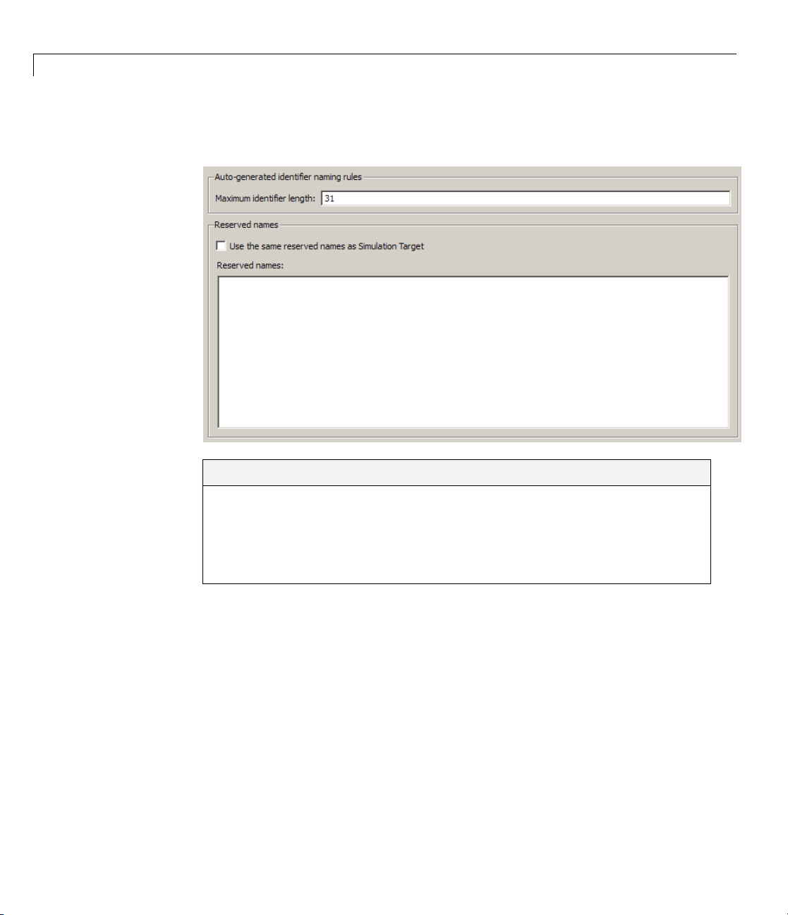
Symbols Overvie
Select the autom
See Also
“Generating S
atically generated identifier nam ing rules.
tructured Text Code from the Model Window” on page 1-20
w
9-13
Page 98

9 Configuration Parameters for Simulink
Maximum identifier length
Specify the maximum number of characters in generated function, type
definition, and variable names.
Settings
Default: 31
Minimum: 31
Maximum: 256
You can use this parameter to limit the number of characters in function,
type definition, and variable names.
Command-Line Information
Parameter: PLC_RTWM axIdLength
Type: int
Value:
Default: 31
®
PLC Coder™ Models
31 to 256
9-14
See Also
“Generating S tructured Text Code from the Model Window” on page 1-20
Page 99

PLC Coder: Symbols
Use the same rese
Specify whether
Simulation Targ
to use the same reserved names as those specified in the
et > Symbols pane.
rvednamesasSimulationTarget
Settings
Default: off
On
Enables usin
Simulation T
Off
Disables u
Simulatio
g the same reserved names as those specified in the
arget > Symbols pane pane.
sing the same reserved names as those specified in the
n Target > Symbols pane pane.
Command-Line Information
r:
Paramete
Type: string
Value:
Default
PLC_RTWUseSimReservedNames
'on' | 'off'
:
'off'
See Also
“Gener
ating Structured Text Code from the Model Window” on page 1-20
9-15
Page 100

9 Configuration Parameters for Simulink
Reserved names
Enter the names o
donotwantmodif
Settings
Default: ()
®
PLC Coder™ Models
f variables or functions in the generated code that y ou
ied.
This action c
code to avoid
must be short
hanges the names of variables or functions in the generated
name conflicts with identifiers in custom code. Reserved names
er than 256 characters.
Tips
• Start each reserved name with a letter or an underscore to prevent error
messages.
• Each reserved name must contain only letters, numbers, or underscores.
• Separate the reserved names using commas or spaces.
Command-Line Information
Parameter: PLC_RTWRese rvedNames
Type: string
Value:
Default: ''
string
See Also
“Generating S tructured Text Code from the Model Window” on page 1-20
9-16
 Loading...