

Page 1

Simulink
®
HDL Coder™
Release Notes
Page 2

How to Contact The MathWorks
www.mathworks.
comp.soft-sys.matlab Newsgroup
www.mathworks.com/contact_TS.html Technical Support
suggest@mathworks.com Product enhancement suggestions
bugs@mathwo
doc@mathworks.com Documentation error reports
service@mathworks.com Order status, license renewals, passcodes
info@mathwo
com
rks.com
rks.com
Web
Bug reports
Sales, prici
ng, and general information
508-647-7000 (Phone)
508-647-7001 (Fax)
The MathWorks, Inc.
3 Apple Hill Drive
Natick, MA 01760-2098
For contact information about worldwide offices, see the MathWorks Web site.
®
Simulink
© COPYRIGHT 2007–20 10 by The MathWorks, Inc.
The software described in this document is furnished under a license agreement. The software may be used
or copied only under the terms of the license agreement. No part of this manual may be photocopied or
reproduced in any form without prior written consent from The MathW orks, Inc.
FEDERAL ACQUISITION: This provision applies to all acquisitions of the Program and Documentation
by, for, or through the federal government of the United States. By accepting delivery of the Program
or Documentation, the government hereby agrees that this software or documentation qualifies as
commercial computer software or commercial computer software documentation as such terms are used
or defined in FAR 12.212, DFARS Part 227.72, and DFARS 252.227-7014. Accordingly, the terms and
conditions of this Agreement and only those rights specified in this Agreement, shall pertain to and govern
theuse,modification,reproduction,release,performance,display,anddisclosureoftheProgramand
Documentation by the federal government (or other entity acquiring for or through the federal government)
and shall supersede any conflicting contractual terms or conditions. If this License fails to meet the
government’s needs or is inconsistent in any respect with federal procurement law, the government agrees
to return the Program and Docu mentation, unused, to The MathWorks, Inc.
Trademarks
MATLAB and Simulink are registered trademarks of The MathWorks, Inc. See
www.mathworks.com/trademarks for a list of additional trademarks. Other product or brand
names may be trademarks or registered trademarks of their respective holders.
Patents
The MathWorks products are protected by one or more U.S. patents. Please see
www.mathworks.com/patents for more information.
HDL Coder™ Release Notes
Page 3

Summary by Version ............................... 1
Contents
Version 1.7 (R2010a) Simulink
Version 1.6 (R2009b) Simulink
Version 1.5 (R2009a) Simulink
Version 1.4 (R2008b) Simulink
Version 1.3 (R2008a) Simulink
Version 1.2 (R2007b) Simulink
Version 1.1 (R2007a) Simulink
®
HDL Coder Software .. 4
®
HDL Coder Software .. 13
®
HDL Coder Software .. 25
®
HDL Coder Software .. 36
®
HDL Coder Software .. 48
®
HDL Coder Software .. 64
®
HDL Coder Software .. 73
Compatibility Summary for Simulink
Software
........................................ 76
®
HDL Coder
iii
Page 4

iv Contents
Page 5

SummarybyVersion
This table provides quick access to what’s new in each version. For
clarification, see “Using Release Notes” on page 1 .
Simulink®HDL Coder™ Release Notes
Version
(Release)
Latest Versi
V1.7 (R2010a
V1.6 (R2009b)
V1.5 (R2009a)
V1.4 (R2
V1.3 (R2008a)
V1.2 (R2007b)
008b)
New Features
and Changes
on
Yes
)
Details
Yes
Details
Yes
Details
Yes
Details
Yes
Details
Yes
Deta
ils
Version
Compatibilit
Consideratio
Yes
Summary
Yes
Summary
Yes
Summary
Yes
Summary
Yes
Summary
Yes
Summ
ary
Fixed Bugs
y
and Known
ns
Problems
Bug Reports
None No
None No
Bug Reports No
Bug Reports No
Bug Re
ports
Related
Documentation
at Web Site
Printable R elease
Notes: PDF
Current product
documentation
No
1 (R2007a)
V1.
Yes
Details
ing Release Notes
Us
e release notes when upgrading to a newer version to learn about:
Us
ew features
• N
No Bug Reports No
1
Page 6

Simulink®HDL Coder™ Release Notes
• Changes
• Potential impact on your existing files and practices
Review the release notes for other MathWorks™ products required for this
product (for example, MATLAB
®
or Simulink®). Determine if enhancements,
bugs, or compatibility considerations in other products impact you.
If you are upgrading from a software version other than the m ost recent one,
review the current release notes and all interim versions. For example, when
you upg rade from V1.0 to V1.2, review the release notes for V1.1 and V1.2.
What Is in the Release Notes
New Features and Changes
• New functionality
• Changes to existing functionality
Version Compatibility Con si derations
When a new feature or change introduces a reported incompatibility between
versions, the Compatibility Considerations subsection explains the
impact.
Compatibility issues reported after the product release appear under Bug
Reports at The MathWorks™ Web site. Bug fixes can sometimes result
in incompatibilities, so review the fixed bugs in Bug Reports for any
compatibility impact.
Fixed Bugs and Known Problems
The MathWorks offers a user-searchable Bug Reports database so you can
view Bug Reports. The development team updates this database at release
time and as more information becomes available. Bug Reports include
provisions for any known workarounds or file replacem ents. Information is
available for bugs existing in or fixed in Release 14SP2 or later. Information
is not avail able for all bugs in earlier releases.
2
Page 7

SummarybyVersion
Access Bug Reports using y our MathWorks Account.
About Functions an d Properties Being Removed
This section lists functions or properties removed or in the process of being
removed. Functions and properties typically go through several stages across
multiple releases before being completely removed. This provides time for you
to make adjustments to your code.
• Announcement — The Release Notes announce the planned removal, but
there are no functional changes; the function runs as it did before.
• Warning — When you run the function, it displays a warning message
indicating it will be removed in a future release; otherwise the function
runs as it did before.
• Error — When you run the function, it produces an error. The error
message indicates the function was removed and suggests a replacement
function, if one is available.
• Removal — When you run the function, it fails. The error message is the
standard message when MATLAB does not recognize an entry.
Functions and properties might be in a stage for one or more releases before
moving to another stage. Functions and properties are listed in the Functions
and Properties Being Removed section only when they enter a new stage
and their behavior changes. For example, if a function displayed a warning
in the previous release and errors in this release, it appears on the list. If it
continues to display a warning, it does not appear on the list because there
was no change between the releases.
Not all functions and properties go through all stages. For example, a
function’s impending removal might not be announced, but instead, the first
notification might be that the function displays a warning.
The Release Notes include actions you can take to mitigate the effects of
function or property removal, such as adapting your code to use a replacement
function.
3
Page 8

Simulink®HDL Coder™ Release Notes
Version 1.7 (R2010a) Simulink HDL Coder Software
This table summarizes what’s new in Version 1.7 (R2010a):
New Features and
Changes
Yes
Details below
Version
Compatibility
Considerations
Yes—Details labeled
as Compatibility
Considerations,
below. See also
Summary.
New features and changes introduced in this version are:
• “Simplified Syntax for Specification of Block Implementations in Control
Files” on page 5
• “HDL Workflow Advisor” on page 7
• “Additional Simulink Blocks Supported for HDL Code Ge neration” on page
8
• “CORDIC Algorithm Supported for Trigonometric Functions (sin, cos,
sincos)” on page 9
• “Option to Minimize Generation of Clock Enables ” on page 10
• “VHDLArchitectureName Property Supports Specification of Architecture
Name” on page 10
Fixed Bugs an d
Known Problems
Bug Reports
Related
Documentation at
Web Site
Printable Release
Notes: PDF
Current product
documentation
• “VHDLLibraryName Property Supports Specification of Target Library ”
on page 10
• “Output Pipelining Now Supported for Subsystems” on page 10
• “Distributed Pipelining Now Supported for Subsystems” on page 11
• “CSD and Factored CSD Optimizations f or Constant Multiplications” on
page 11
• “Enhanced Gain Block Support” on page 11
4
Page 9

Version 1.7 (R2010a) Simulink®HDL Coder™ Software
• “FIR Decimation Filter Supports Distributed Arithmetic Architecture”
on page 12
• “Serial, Partly Serial and Cascade Serial Architectures Supported for FIR
Filter Implementations” on page 12
• “InstancePostfix Property Allows Specification of Extension to Postfix
String” on page 12
Simplified Syntax for Specification of Block
Implementations in Control Files
In R2010a, the coder supports a simplified syntax for specifying block
implementations in a control file. The new syntax lets you specify a block
implementation using simple keywords, instead of
The new implementation keywords are generic, rather than block-specific.
This approach lets you use the same keyword to specify implementation
types such as
Tree, Cascade,orLinear for all blocks that support such
implementations. For example, the following control file specifies that the
coder uses a cascade implementation for all Sum blocks and all Product
blocks in the model.
package.class notation.
function cfg = controlFi le
cfg = hdlnewcontrol(mfilename);
cfg.forEach('*',...
'built-in/Sum', {},...
'Cascade', {});
cfg.forEach('*',...
'built-in/Product', {},...
'Cascade', {});
To specify the the default implementation for any block, simply use the
keyword
'default', as in the following example.
function cfg = controlFi le
cfg = hdlnewcontrol(mfilename);
5
Page 10

Simulink®HDL Coder™ Release Notes
cfg.forEach( './Subsystem/MinMax', ...
'built-in/MinMax', {}, ...
'default');
Refer to “Summary of Block Implementations” in the Simulink®HDL
Coder™ documentation for a complete listing of supported blocks and their
implementations.
Compatibility Considerations
In previous releases, control files specified block implementations using
package.class syntax. For example, the following control file specifies the
cascade implementation for Sum blocks, using
function cfg = controlFil e
cfg = hdlnewcontrol(mfilename);
package.class syntax.
cfg.forEach('*',...
'built-in/Sum', {},...
'hdldefaults.SumCascadeHDLEmission', {});
The coder continues to support control files that use package.class syntax.
However, we strongly recommend that you convert exis ting control files to
the new syntax. To convert an existing control file:
• Open a model that is linked to the control file.
• Open the Configuration Parameters dialog box and select the HDL Coder
pane.
• Click Generate to generate HDL code for the model. The code generation
process updates in-memory information that will be written to your
updated control file.
• In the Code generation control file subpane, click Save. This overwrites
the existing control file. The updated control file will use the new syntax.
6
Page 11

Version 1.7 (R2010a) Simulink®HDL Coder™ Software
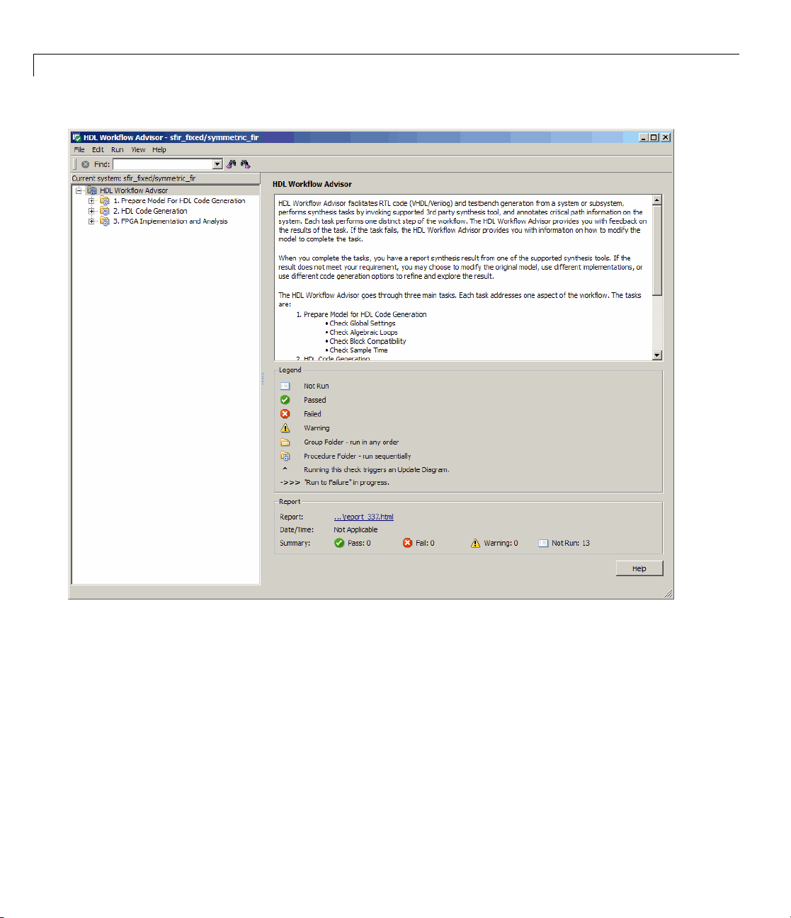
HDL Workflow Advisor
The HDL Workflow Advisor is a GUI tool that supports all stages of the FPGA
design process, including the following:
• Checking the Simulink model for HDL code generation compatibility
• HDL code and test bench generation
• Synthesis and timing analysis through integration with third-party
synthesis tools (r2010a supports Xilinx
®
ISE)
• Back annotation of the Simulink model w ith critical path and other
information obtained during synthesis.
The following figure shows the top-level HDL Workflow Advisor window.
7
Page 12
Simulink®HDL Coder™ Release Notes
See “U sing the HDL Workflow Advisor” for further information.
Additional Simulink Blocks Supported for HDL Code
Generation
The coder now supports the blocks listed in the following table for H D L code
generation.
8
Page 13

Version 1.7 (R2010a) Simulink®HDL Coder™ Software
Block
simulink/Additional Math & Discrete/Additional
Discrete/Unit Delay Enabled Resettable
simulink/Additional Math & Discrete/Additional
Discrete/Unit Delay Resettable
simulink/Math Operations/Trigonometric Function See also “CORDIC Algorithm
Signal Processing Blockset/Signal Operations/Repeat
Communications Blockset/Digital Baseband
Modulation/PM:
• PSK Modulators (BPSK,M-PSK,QPSK)
• PSK Demodulators (BPSK,M-PSK,QPSK)
Communications Blockset/Interleaving/Convolutional:
• Convolutional Interleaver
• Convolutional Deinterleaver
Communications Blockset/Error Detection and
Correction/Convolutional/Viterbi Decoder
Notes
Supported for Trigonometric
Functions (sin, cos, sincos)” on page
9.
“Convolutional Interleaver and
Deinterleaver Block Requirements
and Restrictions”
“Viterbi Decoder Block Requirements
and Restrictions”
“Summary of Block Implementations” in the Simulink HDL Coder
documentation gives a complete listing of blocks that the coder supports for
HDL code generation.
CORDIC Algorithm Supported for Trigonometric
Functions (sin, cos, sincos)
The Simulink Trigonometric Function block now supports the CORDIC
algorithm for the
Simulink HDL Coder HDL Coder now supports HDL code generation for
the Trigonometric Function block for the
sin,cos,andsincos functions.
sin,cos,andsincos functions. To
9
Page 14

Simulink®HDL Coder™ Release Notes
generate HDL code for one these functions, select the Trigonometric Function
block, you must set the Approximation method parameter to
See also “Trigonometric Function Block Requirements and Restrictions” in
the Simulink HDL Coder documentation.
Option to Minimize Generation of Clock Enables
The new Minimize clock enables options lets you suppress generation of
clock enable logic for single-rate designs, wherever possible. If your target
device does not have registers with clock enables, you may want to consider
selecting this option.
CORDIC.
You can also use the command-line property
suppress generation of clock enable logic .
See also “Minimize clock enables” in the Simulink HDL Coder documentation.
MinimizeClockEnable to
VHDLArchitectureName Property Supports
Specification of Architecture Name
The new VHDLArchitectureName property lets you specify the architecture
name for generated HDL code. The default architecture name is
'rtl'.
VHDLLibraryName Property Supports Specification
of Target Library
The new VHDLLibraryName property lets you specify the name of the target
library for generated HDL code. The default target library name is
'work'.
Output Pipelining Now Supported for Subsystem s
The coder now supports the OutputPipeline property for subsystems.
For detailed information, see “O utpu tPipeline” in the Simulink HDL Coder
documentation.“Distributed Pipeline Insertion for Embedded MATLAB
Function Blocks” in the Simulink HDL Coder documentation.
10
Page 15

Version 1.7 (R2010a) Simulink®HDL Coder™ Software
Distributed Pipelining Now Supported for Subsystems
In the previous release, the coder supported the DistributedPipelining
property for Embedded MATLAB®Function blocks or Stateflow®charts
within a subsystem.. In R2010a, the coder also supports this property for
any subsystem.
For detailed information, see “Distributed Pipeline Insertion for Embedded
MATLAB Function Blocks” in the Simulink HDL Coder documentation.
CSD and Factored CSD Optimizations for Constant
Multiplications
You can now specify Canonic Signed Digit (CSD) and Factored Canonic Signed
Digit (FCSD) techniques to optimize multiplication operations involving
constants.
The
ConstMultiplierOptimization implementation supports CSD and
FCSD optimizations for the following blocks:
• Gain
• Stateflow chart
• Truth Table
• Embedded MATLAB
See also “ ConstMultiplierOptimizatio n”.
Enhanced Gain Block Support
The coder now supports the following for HD L code generation for the G ain
block:
• Use of
• If you specify the implementation parameter
ConstMultiplierOptimization, 'auto') for the Gain block, the coder
automatically selects CSD or FCSD implementations based on the number
of required adders.
Matrix (k*u) (u vector) mode for the Gain parameter.
11
Page 16

Simulink®HDL Coder™ Release Notes
FIR Decimation F
Architecture
Thecodenowsupp
for the dspmlti
Implementati
Coder documen
Serial, Part
Supported fo
The coder no
for the foll
• dsparch4/D
• simulink/
• dspmlti4/
You can sp
ReuseAcc
for FIR F
Instanc
Extens
In R 201
you spe
code.
owing blocks:
Discrete/Discrete FIR Filter
FIR Decimation
ecify serial architectures using the
um
ilter Implementations” for further information.]
ePostfix Property Allows Specification of
ion to Postfix String
0a, the coder supports the
cify a string appended after component instance names in generated
The default value for
orts distributed arithmetic (DA) filter implementations
4/FIR Decimation block. See “Distributed Arithmetic
on Parameters for Digital Filter Blocks” in the Simulink HDL
tation for details.
ly Serial and Cascade Serial Architectures
r FIR Filter Implementations
w supports serial, partly serial and cascade serial architectures
igital Filter (FIR structures only)
implementation parameters. See“Speed vs. Area Optimizations
ilter Suppor ts Distributed Arithmetic
SerialPartition and
InstancePostfix. InstancePostfix lets
InstancePostfix is ''(no postfix added).
12
Page 17

Version 1.6 (R2009b) Simulink®HDL Coder™ Software
Version 1.6 (R2009b) Simulink HDL Coder Software
This table summarizes what’s new in Version 1.6 (R2009b):
New Features and
Changes
Yes
Details below
Version
Compatibility
Considerations
Yes—Details labeled
as Compatibility
Considerations,
below. See also
Summary.
New features and changes introduced in this version are:
• “Triggered Subsystems Support for HDL Code Generation” on page 14
• “Stateflow Events Support for HDL Code Generation” on page 14
• “Support for Global Oversampling Clock” o n page 14
• “Test Bench GUI Reorganized” on page 15
• “MATLAB Editor Supports VHDL and VerilogSyntaxHighlighting”on
page 16
• “Hyperlinked Requirements Comments Included in HTML Code
Generation Reports” on page 16
• “HTML Code Generation Report from Root-Level Model Supported” on
page 16
Fixed Bugs an d
Known Problems
None None
Related
Documentation at
Web Site
• “Generation of Simulink Model for Cosimulation of Generated HDL Code”
on page 17
• “Additional Simulink Blocks Supported for HDL Code Generation” on
page 17
• “New hdldemolib Block Supports Streaming FFT” on page 18
• “Algebraic Loops Disallowed for HD L Code G ene ration” on page 18
13
Page 18

Simulink®HDL Coder™ Release Notes
• “DUT Argument Required for checkhdl and makehdl Commands” on page
18
• “AddClockEnablePort Implementation Parameter for RAM Blocks
Deprecated” on page 19
• “Additional Lookup Table Blocks Supported” on page 20
• “Discrete FIR Filter Supports Distributed Arithmetic Architecture” on
page 21
• “Generation of Multicycle Path Co n straintInformation”onpage21
• “Biquad Filter and Digital Filter Blocks Support Complex Input Data and
Coefficients” on page 22
• “Support for Adding or Removing HDL Configuration Component” on
page 23
Triggered Subsystems Support for HDL Code
Generation
The coder now supports HDL code generation for triggered subsystems. See
“Code Generation for Enabled and Triggered Subsystems” in the Simulink
HDL Coder documentation for further information.
14
Stateflow Events Support for HDL Code Generation
The coder now supports a single input event and unlimited output events
in Stateflow charts. f or further information, see “Using I n put and Outp u t
Events” in the Simulink HDL Coder documentation.
Support for Global Oversampling Clock
You can now generate global clock logic that allows you to integrate your DUT
into a larger system easily, without using Upsample or Downsample blocks.
To generate global clock logic, you specify an oversampling factor.The
oversampling factor expresses the desired rate of the global oversampling
clockasamultipleofthebaserateofthemodel. Whenyouspecifyan
oversampling factor, the coder generates the global oversampling clock. Then,
it derives the required timing signals from the clock signal. Generation of the
Page 19

Version 1.6 (R2009b) Simulink®HDL Coder™ Software
global oversampling clock affects only generated HDL code. The clock does
not affect the simulation behavior of your model.
You can specify the desired factor as the Oversampling factor option in the
Clock settings se ction of the Global Settings pane of the Configuration
Parameters dialog. The following figureshowstheoption. Alternatively,you
can set the command-line property
'Oversampling'.
See “Generating a Global Oversampling Clock” in the Simulink HDL Coder
documentation for further information.
Test Bench GUI Reor ganized
The new Testbench generation output section of the GUI contain s three
new options:
15
Page 20

Simulink®HDL Coder™ Release Notes
• HDL test bench: Selecting this option enables generation of an HD L
test bench, and also enables all options in the Configuration section of
the Test Bench pane.
• Cosimulation blocks: Selecting this option enables generation of a model
containing HDL Cosimulation block for use in testing the DUT. Selecting
this option also enables all options in the Configuration section o f the
Test Bench pane.
• Cosimulation model for use with: This option enables generation of a
model containing an HDL Cosimulation block for use in testing with a
selected cosimulation tool. Selecting this option also enables all options in
the Configuration section of the Test Bench pane.
To configure test bench options and generate test bench code, s ele ct one or
more of the options of the Testbench generation o utput section. If you
deselect all three optio ns of the Testbench generation output section, the
coder disables all options in the Configuration section of the Test Bench
pane.
16
MATLAB Editor Supports VHDL and Verilog Syntax
Highlighting
The MATLAB Editor now supports syntax highlighting for VHDL and Verilog
code. See “Highlighting Syntax to Help Ensure Correct Entries” in the
MATLAB documentation for further information on syntax highlighting.
Hyperlinked Requirements Comments Included in
HTML Code Generation Reports
The coder now renders requirements comments as hyperlinked comments
within generated HTML code generation reports. See “Requirements
Comments and Hyperlinks” in the Simulink HDL Coder documentation for
further information.
HTML Code Generation Report from Root-Level Model
Supported
In previous releases, the coder did not support generation of HTML code
generation reports from the root-level model. R2009b removes this restriction.
Page 21

Version 1.6 (R2009b) Simulink®HDL Coder™ Software
You can now generate reports for the root-level model as well as for
subsystems, blocks, Stateflow charts, or Embedded M ATLA B blocks.
Generation of Simulink Model for Cosimulation of
Generated HDL Code
The coder now supports generation of a Simulink model configured for:
• Simulink simulation of your design
• Cosimulation of your design with an HDL simulator
The generated model includes a behavioral model of your design and a
corresponding HDL Cosimulation block, configured to cosimulate the design
using EDA Simulator Link™. You can generate an HDL Cosimulation block
foreitherofthefollowing:
• EDA Simulator Link for use with Mentor Graphics
• EDA Simulator Link for use with Cadence Incisive
See “Generating a Simulink M odel fo r Cosimulation with an HDL Si m ulator”
for further information.
Additional Simulink Blocks Supported for HDL Code
Generation
The coder now supports the blocks listed in the following table for H D L code
generation.
Block Implementation
hdldemolib/HDL Streaming FFT hdldefaults.FFT
Ports & Subsystems/Trigger hdldefaults.TriggerPort
simulink/Discrete/Discrete FIR Filter
simulink/Lookup Tables/Direct Lookup Table
(n-D)
hdldefaults.DiscreteFIRFilterHDLInstantiation
hdldefaults.DirectLookupTable
®
ModelSim
®
®
17
Page 22

Simulink®HDL Coder™ Release Notes
Block Implementation
simulink/Lookup Tables/Lookup Table (n-D) hdldefaults.LookupTableND
simulink/Lookup Tables/Prelookup
“Summary of Block Implementations” in the Simulink HDL Coder
documentation gives a complete listing of blocks that the coder supports for
HDL code generation.
New hdldemolib Block Supports Streaming FFT
The new hdldemolib/HDL Streaming FFT block supports a Radix-2 DIF
streaming FFT algorithm.
See “HDL Streaming FFT” in the Simulink HDL Coder documentation for
details.
Algebraic Loops Disallowed for HDL Code Generation
The coder now checks for algebraic loops during the compatibility checking
phase of the code generation process. If
inside the DUT, the coder displays an error message and ends the code
generation process.
Compatibility Considerations
Restructure any of your models that contain algebraic loops such that
algebraic loops do not occur. It is also good practice to set the Algebraic
loop diagnostic in the Diagnostics pane of the Configuration Parameters
dialog box to
error.
hdldefaults.PreLookup
makehdl detects an algebraic loop
18
DUT Argument Required for checkhdl and makehdl
Commands
R2009b requires that calls to the following functions must specify the device
under test (DUT):
•
checkhdl
Page 23

Version 1.6 (R2009b) Simulink®HDL Coder™ Software
• makehdl
When you call checkhdl or makehdl, specify the DUT as the initial argument
to these functions, as in the following example:
makehdl('sfir_fixed/symmetric_fir','TargetLanguage', 'Verilog');
As in previous releases, you can specify the DUT in any of the following forms:
•
bdroot: the current model.
'modelname': an explicitly specified model.
•
'modelname/subsys': explicitly specified path to a subsystem.
•
gcb: the currently selected subsystem
•
This requirement avoids certain ambiguities that occurred in calls to
checkhdl or makehdl that did not pass in an explicit DUT argument.
In R2009b, the coder displays a warning if it encounters a call to
checkhdl
or makehdl without the DUT argument. In future releases, the coder will
generate an error if it encounters a call to either of these functions without
the DUT argument.
See also the checkhdl and makehdl function reference pages in the Simulink
HDL Coder documentation.
Compatibility Considerations
If your MATLAB files contain any calls to checkhdl or makehdl that do not
specify the DUT, modify them to pass in the DUT as the initial argument.
AddClockEnablePort Implementation Parameter for
RAM Blocks Deprecated
The AddClockEnablePort implementation parameter for the Dual Port RAM
and Single Port RAM blocks is deprecated. The coder issues an error message
if it detects a reference to
AddClockEnablePort in a control file.
19
Page 24

Simulink®HDL Coder™ Release Notes
Compatibility Considerations
If you use the AddClockEnablePort in a control file to suppress to generation
of a clock enable signal for RAM blocks:
• Remove all references to
• Use the generic RAM templates instead. The generic RAM templates
do not use a clock enable signal for RAM structures. The generic RAM
template implements clock e nable with logic in a wrapper around the RAM.
Consider the generic RAM style if
AddClockEnablePort from your control files.
- Your synthesis tool does not support RAM structures with a clock enable
- Your synthesis tool cannot map generated HDL code to FPGA RAM
resources.
To learn how to use generic style RAM for your design, see the new Getting
Started with RAM and ROM in Simulink demo. To open the demo, type the
following command at the M ATLAB prompt:
hdlcoderramrom
Additional Lookup Table Blocks Supported
The coder now supports the following lookup table (LUT) blocks for HDL
code generation:
• simulink/Lookup Tables/Lookup Table (n-D)
• simulink/Looku p Tables/Prelookup
• simulink/Lookup Tables/Direct Lookup Table (n-D)
20
Expanded LUT functionality supported for these blocks includes:
• Tables of two dimensions
• Prelookup
• Interpolation
• Extrapolation
Page 25

Version 1.6 (R2009b) Simulink®HDL Coder™ Software
See “Using Lookup Table Blocks” in the Simulink HDL Coder documentation
for details.
Discrete FIR Filter Supports Distributed Arithmetic
Architecture
The code now supports distributed arith metic(DA)filterimplementationsfor
the Discrete FIR Filter b lock. See “Distributed Arithmetic Implementation
Parameters for Digital Filter Blocks” in the Simulink H D L Coder
documentation for details.
Generation of Multicycle Path Constraint Information
The coder now supports generation of a text file that reports multicycle path
constraint information. You can use this information with your synthesis tool.
To generate the file, select the Generate multicycle path information
option in the EDA Tool Scripts pane of the Configuration Parameters dialog
box. The following figure shows this option.
21
Page 26

Simulink®HDL Coder™ Release Notes
22
To generate a multicycle path constraint information file at the command line,
set the
See “Generating Multicycle Path Information Files” in the Simulink HDL
Coder documentation for detailed information.
MulticyclePathInfo property as shown in the following example.
makehdl(gcb,'MulticyclePathInfo', 'on');
Biquad Filter and Digital Filter Blocks Support
Complex Input Data and Coefficients
The Biquad Filte r and Digital Filter blocks now support complex input data
and coefficients for all filter structures except decimators and interpolators.
Page 27

Version 1.6 (R2009b) Simulink®HDL Coder™ Software
Support for Adding or Removing HDL Configuration
Component
The HDL Coder submenu of the Tools menu now supports addition or
removal of the HDL Coder configuration component of a model. The following
figure shows the Remove HDL Configuration to Model option.
23
Page 28

Simulink®HDL Coder™ Release Notes
See “Adding and Removing the HDL Configuration Component” Simulink
HDL Coder documentation for more information.
24
Page 29

Version 1.5 (R2009a) Simulink®HDL Coder™ Software
Version 1.5 (R2009a) Simulink HDL Coder Software
This table summarizes what’s new in Version 1.5 (R2009a):
New Features and
Changes
Yes
Details below
Version
Compatibility
Considerations
Yes—Details labeled
as Compatibility
Considerations,
below. See also
Summary.
New features and changes introduced in this version are:
• “hdlsupported Library Reorganized” on page 26
• “HTML Code Generation Report” on page 26
• “Additional Simulink Blocks Supported for HDL Code Generation” on
page 28
• “Enabled Subsystems Supported for HDL Code Generation” on page 29
• “New Default HDL Implementations for Selected Blocks” on page 30
• “New HDL Implementations for Selected Blo cks” on page 31
• “Distributed Arithmetic Implementations for the Digital Filter Block” on
page 32
Fixed Bugs an d
Known Problems
None None
Related
Documentation at
Web Site
• “Complex Data Supported for the Digital Filter Block” on page 32
• “Requirements Comments Included in Generated Code” on page 33
• “Restriction on fi and fimath Rounding Modes in Embedded MATLAB
Function Block Remov ed” on page 33
• “Restriction on for Loop Increment in Embedded MATLAB Function Block
Removed” on page 34
• “Generic RAM Template Supports RAM Without a Clock Enable Signal”
on page 34
25
Page 30

Simulink®HDL Coder™ Release Notes
• “Generating ROM with Lookup Table and Unit Delay Blocks” on page 35
hdlsupported Library Reorganized
The hdlsupported.mdl block library has been reorganized into several
sublibraries to help you locate the HDL-compatible blocks you need more
easily. The following figure shows the top-level view of the
library.
hdlsupported.mdl
26
The set of supported blocks will change in future releases of the coder. To
keep the
you install a new release. See “Supported Blocks Library” in the Simulink
HDL Coder documentation for further information.
hdlsupported.mdl current, you should rebuild the library each time
HTML Code Generation Report
To help you navigate more easily between generated code and your source
model, the coder provides a traceability option that lets you generate reports
from either the GUI or the co mmand line. When you enable traceability,
the coder creates and displays an HTML code generation report during the
code generation proce ss. The following figure shows the top-level page of
a typical report.
Page 31

Version 1.5 (R2009a) Simulink®HDL Coder™ Software
The report comprises several sections:
• The Summary section lists version and date information.
• The Generated Source Files table contains hyperlinks to that let you
view generated HDL code in a MATLAB Web browser window. This view
of the code includes hyperlinks that let you view the blocks or subsystems
from which the code was generated. You can click the names of source code
files generated from your model to view their contents in a MATLAB Web
browser window. The report supports two types of linkage between the
model and generated code:
- Code-to-model hyperlinks within the displayed source code let you view
the b locks or subsystems from which thecodewasgenerated. Clickon
the h yperlinks to view the relevant blocks or subsystems in a Simulink
model window.
- Model-to-code linkage lets you view the generated code for any block in
the model. To highlight a block’s generated code in the HTML report,
right-click the block and select HDL Coder > Navigate to Code from
the context menu.
• The Traceability Report allows you to account for Eliminated / V irtual
Blocks that are untraceable, versus the listed Traceable Simulink
Blocks / Stateflow Objects / Embedded MATLAB Scripts,providinga
complete mapping between model elements and code.
27
Page 32

Simulink®HDL Coder™ Release Notes
To enable generation of the HTML code generation report, select Generate
traceability report in the HDL Coder pane of the Configuration
Parameters dialog box, as shown in the following figure.
28
See “Cr
Coder
Addi
Gene
The c
gene
eating and Using a Code Generation Report” in the Simulink HDL
documentation for further information.
tional Simulink Blocks Supported for HDL Code
ration
oder now supports the blocks listed in the following table for HDL code
ration.
Page 33

Version 1.5 (R2009a) Simulink®HDL Coder™ Software
Block Implementation(s)
simulink/Additional Math & Discrete/
Additional Math: Increm ent Decrement/Decrement Real World
simulink/Additional Math & Discrete/
Additional Math: Increm ent Decrement/Increment Real World
simulink/Additional Math & Discrete/
Additional Math: Increm ent Decrement/Decrement Store Integer
simulink/Additional Math & Discrete/
Additional Math: Increm ent Decrement/Increment Store Integer
simulink/Discontinuties/Saturation Dynamic default
simulink/Math Operations/Reciprocal Sqrt default, SqrtFunction
Signal Routing/Go To default
Signal Routing/From default
dsparch4/Biquad Filter
default
default
default
default
RecipSqrtNewton
SqrtBitset
SqrtNewton
default
Ports & Subsystems/Enable default
See “Summary of Block Implementations” in the Simulink HDL Coder
documentation for a complete listing of blocks that are currently supported
for HDL code generation.
Enabled Subsystems Supported for HDL Code
Generation
The code now supports code generation for enabled subsystems, provided
that they are configured as described in “Code Generation for Enabled and
Triggered Subsystems” in the Simulink HDL Coder documentation.
29
Page 34

Simulink®HDL Coder™ Release Notes
New Default HDL Implementations for Selected
Blocks
The default HDL implementations for certain blocks has been changed. The
following table lists these blocks, as well as their new default implementations
and previous default implementations. All listed implementation classes
belong to the package
hdldefaults.
Block
simulink/Commonly Used
Blocks/Constant
simulink/Commonly Used
Blocks/Ground
dspsrcs4/DSP Constant
simulink/Commonly Used
Blocks/Demux
simulink/Commonly Used
Blocks/Mux
simulink/Commonly Used
Blocks/Switch
simulink/Math
Operations/Complex to
Real-Imag
simulink/Math
Operations/Real-Imag to
Complex
See “Summary of Block Implementations” in the Simulink HDL Coder
documentation for a complete listing of blocks that are currently supported
for HDL code generation.
Default Implementation
Before R2009a
ConstantHDLEmission Constant
DemuxHDLEmission
MuxHDLEmission
SwitchHDLEmission SwitchRTW
ComplexToRealImagHDLEmission ComplexToRealImag
RealImagtoComplexHDLEmission RealImagtoComplex
New Default
Implementation
Demux
Mux
30
Compatibility Considerations
If your models use default HDL block implementations for the affected blocks,
the coder now defaults to the new implementations. T he new implementations
Page 35

Version 1.5 (R2009a) Simulink®HDL Coder™ Software
are compatible with the previous implementations and will produce identical
results.
The older implementations for the listed blocks will be supported for a limited
number of future releases. If your control files explicitly reference the previous
default implementation for any of the affected blocks, the coder will continue
to use the referenced implementation. You should consider removing or
changing such references in your control files to use the new implementations.
New HDL Implementations for Selected Blocks
A number of HDL block implementations have been changed. The following
table lists these blocks, as well as their new implementations and the earlier
implementations that they replace. All lis ted implementation classes belong
to the package
hdldefaults.
Block Implementation
Before R2009a
simulink/Math
Operations/MinMax
dspstat3/Maximum
dspstat3/Minimum
simulink/Commonly Used
Blocks/Sum
simulink/Math Operations/Sum of
Elements
simulink/Commonly Used
Blocks/Product
simulink/Math
Operations/Product of Elements
simulink/Commonly Used
Blocks/Sum
simulink/Math Operations/Sum of
Elements
simulink/Commonly Used
Blocks/Product
simulink/Math
Operations/Product of Elements
MinMaxCascadeHDLEmission MinMaxCascade
SumTreeHDLEmission SumTree
ProductTreeHDLEmission ProductTree
SumCascadeHDLEmission SumCascade
ProductCascadeHDLEmission ProductCascade
New Implementation
31
Page 36

Simulink®HDL Coder™ Release Notes
See “Summary of Block Implementations” in the Simulink HDL Coder
documentation for a complete listing of blocks that are currently supported
for HDL code generation.
Compatibility Considerations
The n ew implementations are compatible with the previous implementations
and will produce identical results.
The older implementations for the listed blocks will be supported for a limited
number of future releases. If your control files explicitly reference the
previous implementation for any of the affected blocks, the coder will continue
to use the referenced implementation. You should consider removing or
changing such references in your control files to use the new implementations.
Distributed Arithmetic Implementations for the Digital
Filter Block
Distributed Arithmetic (DA) is a widely used technique for implementing
sum-of-products computations without using multipliers. DA distributes
multiply and accumulate operations acro ss shifters, lookup tables (LUTs) and
adders in such a way that conventional multipliers are not required. The
coder now supports DA implementations for the following FIR structures of
the Digital Filter block:
32
•
dfilt.dffir
• dfilt.dfsymfir
• dfilt.dfasymdir
See “Block Implementation Parameters” in the Simulink HDL Coder
documentation for further information.
Complex Data Supported for the Digital Filter Block
The coder supports complex coefficients and complex input signals for fully
parallelFIRandCICfilterstructures of the Digital Filter block. In many
cases, you can use complex data and complex coefficients in combination. The
following table shows the filter structures that support complex data and/or
coefficients, and the permitted combinations.
Page 37

Version 1.5 (R2009a) Simulink®HDL Coder™ Software
Filter Structure Complex
Data
Complex
Coefficients
Both Complex
Data
and Coefficients
dfilt.dffir
dfilt.dfsymfir
dfilt.dfasymfir
dfilt.dffirt
mfilt.cicdecim
mfilt.cicinterp
mfilt.firdecim
mfilt.firinterp
YY Y
YY Y
YY Y
YY Y
Y
Y
N/A N/A
N/A N/A
YY N
YY N
See “Blocks That Support Complex Data” for further information on how the
coder supports use of complex data.
Requirements Comments Included in Generated Code
Requirements that you assign to Simulink blocks are now automatically
included as comments in generated code . See the Simulink
Validation™ User’s Guide in the Simulink HDL Coder documentation for
further information on requirements comments.
®
Verification and
RestrictiononfiandfimathRoundingModesin
Embedded MATLAB Function Block Removed
In previous releases, the coder did not support the convergent and round
modes for the fi and fimath functions in Embedded MATLAB Function
blocks.
This restriction has been removed; the coder no w supports all
rounding modes.
See also “Generating HDL Code with the Embedded MATLAB Function
Block” in the Simulink HDL Coder documentation.
fi and fimath
33
Page 38

Simulink®HDL Coder™ Release Notes
RestrictiononforLoopIncrementinEmbedded
MATLAB Function Block Removed
In previous releases, the use of for loops with an increment other than 1 in
an Embedded MATLAB Function Block was not supported for HDL code
generation.
This restriction has been removed. The coder now allows use of any increment
in a
for loop in an Embedded MATLAB Function Block.
See also “Generating HDL Code with the Embedded MATLAB Function
Block” in the Simulink HDL Coder documentation.
Generic RAM Template Supports RAM Without a
Clock Enable Signal
The hdldemol ib library provides three type of RAM blocks:
• Dual Port RAM
34
• Simple Dual Port RAM
• Single Port RAM
These blocks (see “RAM Blocks” in the Simulink HDL Coder documentation)
implement RAM structures using HDL templates that include a clock enable
signal.
However, some synthe sis tools do not support RAM inference with a clock
enable. As an alternative, the coder now provides a generic style of HDL
templatesthatdonotuseaclockenablesignalfortheRAMstructures. The
generic RAM template implements clock enable with logic in a wrapper
around the RAM.
You may want to use the generic RAM style if your synthesis tool does not
support RAM structures w ith a clock enable, and cannot map generated HDL
code to FPGA RAM resources. To learn how to use generic style RAM for your
design, see the new Getting Started with RAM and ROM in Simulink demo.
To open the dem o, type the following command at the MATLAB prompt:
hdlcoderramrom
Page 39

Version 1.5 (R2009a) Simulink®HDL Coder™ Software
Generating ROM with Lookup Table and Unit Delay
Blocks
Simulink HD L Coder does not provide a ROM block, but you can easily build
one using basic Simulink blocks. The new Getting Started with RAM and
ROM in Simulink demo includes an example in which a ROM is built using
a Lookup Table block and a Unit Delay block. To open the demo, type the
following command at the M ATLAB prompt:
hdlcoderramrom
35
Page 40

Simulink®HDL Coder™ Release Notes
Version 1.4 (R2008b) Simulink HDL Coder Software
This table summarizes what’s new in Version 1.4 (R2008b):
New Features and
Changes
Yes
Details below
Version
Compatibility
Considerations
Yes—Details labeled
as Compatibility
Considerations,
below. See also
Summary.
New features and changes introduced in this version are:
• “New hdldemolib Blocks Support FFT, HDL Counter, and Bitwise
Operators” on page 37
• “Additional Simulink Blocks Supported for HDL Code Generation” on
page 39
• “Complex Signals Supported for Additional Blocks” on page 39
• “CodeAnnotationSupport”onpage40
• “New Constant Block Implementation Indicates Hi-Z or Unknown States”
on page 41
• “New Test Bench Reference Postfix O ption” on page 41
Fixed Bugs an d
Known Problems
Bug Reports No
Related
Documentation at
Web Site
36
• “New Default HDL Implementations for Selected Blocks” on page 43
• “Default Entity C onflict Postfix Changed” on page 4 4
• “New DistributedPipelining Implementation Parameter for Embedded
MATLAB Function Blocks and Stateflow Charts” on page 44
• “Coefficient Multiplier Optimization for Digital Filter, FIR Decimation, and
FIR Interpolation Filters” on page 45
• “hdlnewblackbox Function Generates Black B ox Control Statements” on
page 46
Page 41

Version 1.4 (R2008b) Simulink®HDL Coder™ Software
• “hdlnewcontrolfile Function Optionally Returns Result to String” on page
47
• “-novopt Flag Added to Default Simulation Command in Generated
Compilation Scripts” on page 47
New hdldemolib Blocks Support FFT, HDL Counter,
and Bitwise Operators
The hdl demo lib library now includes HDL-specific block implementations
supporting simulation and code generation for:
• Counter with count-limited and free-running modes (see “HDL Counter” in
the Simulink HDL Coder documentation)
• Minimum resource FFT (see “HDL FFT” in the Simulink HDL Coder
documentation)
• Bitwise operations, including bit slice, bit reduction, bit concatenation,
bitshift,andbitrotation(see“BitwiseOperators”intheSimulinkHDL
Coder documentation)
The following figure shows the
hdldemolib Block Library” in the Simulink HDL Coder documentatio n for
more information about the library.
hdldemolib library window. See “The
37
Page 42

Simulink®HDL Coder™ Release Notes
38
Page 43

Version 1.4 (R2008b) Simulink®HDL Coder™ Software
Additional Simulink Blocks Supported for HDL Code
Generation
The co der now suppo rts the following blocks for HDL code generation:
• Signal Processing Blockset/M ultirate Filters/CIC Interpolation
• Signal Processing Blockset/M ultirate Filters/FIR Interpolation
(See the dem o “Digital Down Converter for HDL Code Generation” for
an example of the use of this block.)
• Signal Processing Blockset/Filtering /Adaptive Filters/LMS Filter
(See the demo “Adaptive Noise Canceler with LMS Filter” for an example
of the use of this block.)
• simulink/Logic and Bit Operations/Extract Bits
• simulink/Math Operations/Math Function (now supports
transpose functions for HDL code generation)
• simulink/Model-Wide Utilities/DocBlock
• Stateflow Truth Table
In addition, several HDL-specific block implementations have been added to
the
hdldemolib library. See “New hdldemolib Blocks Support FFT, HDL
Counter, and Bitwise Operators” on page 37.
See “Summary of Block Implementations” in the Simulink HDL Coder
documentation for a complete listing of blocks that are currently supported
for HDL code generation.
hermitian,and
Complex Signals Supported for Additional Blocks
In the previous release, the coder introduced support for use of complex
signals with a limited set of blocks. In R2008b, the coder supports complex
signals for these additional blocks:
• dspadpt3/LMS Filter
• dspsigattribs/Frame Conversion
• dspsigops/Delay (
DSPDelayHDLEmission implementation)
39
Page 44

Simulink®HDL Coder™ Release Notes
• hdldemolib/Dual Port RAM
• hdldemolib/Simple Dual Port RAM
• hdldemolib/Single Port RAM
• hdldemolib/HDL FFT
• simulink/Commonly Used Blocks/Relational Operator (
only)
• simulink/Discrete/Memory
• simulink/D iscre te/Zero-Order Hold
• simulink/Logic and Bit Operations/Compare To Constant
• simulink/Logic and Bit Operations/Compare To Zero
• simulink/Lookup Tables/Lookup Table (
implementation)
• simulink/Math Operations/Assignment
• simulink/Math Operations/Math Function (
• simulink/Signal Attributes/Signal Specification
See “Blocks That Support Com plex Data” in the Simulink HDL Coder
documentation for a complete listing of blocks that support complex signals.
LookupHDLInstantiation
hermitian, transpose)
~= and == operators
Code Annotation Support
The coder now lets you add text annotations to generated code, in the form of
comments. There are two ways to add annotations to your code:
• Enter text directly on the block diagram as Simulink annotations.
40
• Place a DocBlock at the desired level of your model and enter text
comments.
See “Annotating Generated Code with C omments and Requirements” in the
Simulink HDL Coder documentation for further information.
Page 45

Version 1.4 (R2008b) Simulink®HDL Coder™ Software
New Constant Blo
or Unknown State
The coder now sup
(
hdldefaults.
when a constan
The implement
follows:
•
{Value, 'Z'}
block emits t
4-bit signal
{Value, 'Z'
•
{Value, 'X'
emits the c
signal,
hdldefau
data type
See also
documen
'X
lts.ConstantSpecialHDLEmission
.
“Blocks with Multiple Implementations” in the Simulink HDL Coder
tation.
ports an implementation for the built-in/Constant block
ConstantSpecialHDLEmission
t signal is in high-impedance (
ation provides the
: If the signal is in a high-impedance state, the Constant
he character
,
'ZZZZ' would be emitted.
}
is the default value for this implementation.
}
: If the signal is in an unknown state, the Constant block
haracter
XXX'
'X' for each bit in the signal. For example, for a 4-bit
would be emitted.
ck Implementation Indicates Hi-Z
s
),whichyoucanusetoindicate
'Z') or unknown ('X') state.
{Value} parameter to indicate the state, as
'Z' for each bit in the signal. For example, for a
does not support the double
New Tes
The new
) lets you customize the names of re ference signals generated in test
figure
bench
The de
t Bench Reference Postfix Option
Test bench reference postfix option (shown in the following
code by specifying a string to be appended to reference signal names.
fault string is
'_ref'.
41
Page 46

Simulink®HDL Coder™ Release Notes
42
If you generate test bench code via the makehdltb function, use the
Testbenchreferencepostfix property (see TestBenchReferencePostFix in
the in the Simulink HDL Coder documentation) to specify the postfix string.
Page 47

Version 1.4 (R2008b) Simulink®HDL Coder™ Software
New Default HDL Implementations for Selected
Blocks
The default HDL implementations for certain blocks has been changed. The
following table lists these blocks, as well as their new default implementations
and previous default implementations. All listed implementation classes
belong to the package
hdldefaults.
Block
simulink/Commonly Used
Blocks/Data Type Conversion
simulink/Commonly Used
Blocks/Product
simulink/Math
Operations/Divide
simulink/Math
Operations/Product of
Elements
simulink/Commonly Used
Blocks/Sum
simulink/Math
Operations/Add
simulink/Math
Operations/Sum of Elements
simulink/Math
Operations/Subtract
simulink/Commonly Used
Blocks/Unit Delay
Default Implementation
Before Release R2008b
DataTypeConversionHDLEmission DataTypeConversionRTW
ProductLinearHDLEmission ProductRTW
ProductLinearHDLEmission ProductRTW
ProductLinearHDLEmission ProductRTW
SumLinearHDLEmission SumRTW
SumLinearHDLEmission SumRTW
SumLinearHDLEmission SumRTW
SumLinearHDLEmission SumRTW
UnitDelayHDLEmission UnitDelayRTW
New D efault
Implementation
simulink/Math
Operations/MinMax
dspstat3/Maximum MinMaxTreeHDLEmission MinMaxTree
dspstat3/Minimum MinMaxTreeHDLEmission MinMaxTree
MinMaxTreeHDLEmission MinMaxTree
43
Page 48

Simulink®HDL Coder™ Release Notes
Compatibility Considerations
If your models use default HDL block i mplementations for the affected
blocks, the coder will now default to the new implementations. The new
implementations are compatible with the previous implementations and will
produce identical results.
The older implementations for the listed blocks will be supported for a limited
number of future releases. If your control files explicitly reference the previous
default implementation for any of the affected blocks, the coder will continue
to use the referenced implementation. You should consider removing or
changing such references in your control files to use the new implementations.
Default Entity Conflict Postfix Changed
The default value for the Entity conflict postfix property (and the
corresponding CLI property,
from
'_entity' to '_block' .
Compatibility Considerations
If your models or scripts rely on the previous default value ('_entity')for
the Entity conflict postfix property, you will need to explicitly set the
property value to
EntityConflictPostfix) has been changed
'_entity'.
44
New DistributedPipelining Implementation
Parameter for Embedded MATLAB Function Blocks
and Stateflow Char ts
In the previous release, the coder introduced automatic pipeline insertion,
a special optimization for HDL code generated from Embedded MATLA B
Function blocks or Stateflow charts. This optimization was enabled implicitly
by specifying the
file for these blocks.
In the current release, the new
you explicitly enable or d isable pipeline insertion, independently from the
OutputPipeline parameter. The control file listed in the following example
specifies two pipeline registers, with
{'OutputPipeline', nStages} parameter in a control
DistributedPipelining parameter lets
DistributedPipelining enabled.
Page 49

Version 1.4 (R2008b) Simulink®HDL Coder™ Software
function c = pipeline_control
c = hdlnewcontrol(mfilename);
c.forEach('*',...
'eml_lib/Embedded MATLAB Function', {},...
'hdlstateflow.StateflowHDLInstantiation', {'OutputPipeline', 2, 'DistributedPipelining', 'on'});
The Distri bute dPipelining property applies only to Embedded MATLAB
Function blocks or Stateflow charts within a subsystem.
For detailed information, see “Distributed Pipeline Insertion for Embedded
MATLAB Function Blocks” in the Simulink HDL Coder documentation.
Compatibility Considerations
If your existing control files specified automatic pipelining implicitl y using the
OutputPipeline parameter, you should change your control files to specify
automatic pipelining explicitly as in the following code excerpt:
c.forEach('*',...
'eml_lib/Embedded MATLAB Function', {},...
'hdlstateflow.StateflowHDLInstantiation', {'OutputPipeline', 2, 'DistributedPipelining', 'on'});
Coefficient Multiplier Optimization for Digital Filter,
FIR Decimation, and FIR Interpolation Filters
The CoeffMultipliers implementation parameter lets you specify use of
canonic signed digit (CSD) or factored CSD optimizations for processing
coefficient multiplier operations in code generated for certain filter blocks.
Specify the
syntax:
•
{'CoeffMultipliers', 'csd'}: Use CSD techniques to replace multiplier
operations with shift and add operations. CSD techniques minimize the
number of addition operations required for constant multiplication by
representing binary numbers with a minimum count of nonzero digits.
This decreases the area used by the filter while maintaining or increasing
clock speed.
CoeffMultipliers parameter in a control file using the following
45
Page 50

Simulink®HDL Coder™ Release Notes
• {'CoeffMultipliers', 'factored- csd'}: Use factored CSD techniques,
which replace multiplier operations with shift a nd add operations on prime
factors of the coefficients. This option lets you achieve a greater filter area
reduction than CSD, at the cost of decreasing clock speed.
•
{'CoeffMultipliers', 'multipliers'} (default): Retain multiplier
operations.
The coder supports
shown in the following table.
Block Implementation
dsparch4/Digital Filter
dspmlti4/FIR Decimation
dspmlti4/FIR Interpolation
See also “ Bl ock Implementati on Parameters” in the Simulink HDL Coder
documentation.
CoeffMultipliers for the filter block implementations
hdldefaults.DigitalFilterHDLInstantiation
hdldefaults.FIRDecimationHDLInstantiation
hdldefaults.FIRInterpolationHDLInstantiation
hdlnewblackbox Function Generates Black Box
Control Statements
The hdlnewblackbox function provides a simple way to create the control
file statements that are required to generate black box interfaces for one
or more subsystems.
Given a selection of one or more subsystems from your mod el,
returns the following as string data in the MATLAB workspace for each
selected subsystem:
• A
forEach call coded with the correct modelscope, blocktype, and default
implementation class (
for the block.
SubsystemBlackBoxHDLInstantiation)arguments
hdlnewblackbox
46
• (Optional) A cell array of strings enumerating the available
implementations classes for the subsystem, in
• (Optional) A cell array of cell arrays of strings enumerating the names of
implementation parameters (if any) corresponding to the implementation
package.class form.
Page 51

Version 1.4 (R2008b) Simulink®HDL Coder™ Software
classes. hdlnewblackbox doesnotlistdatatypesandotherdetailsof
implementation parameters.
For further information, see “Generating a Black Box Interface for a
Subsystem” in the Simulink HDL Coder documentation.
hdlnewcontrolfile Function Optionally Returns Result
to String
The hdlnewcontrolfile function (optionally) now can return control
statements to a string variable.
To return control statements as text in the string variable
returning a control file, use the following syntax:
t = hdlnewcontrolfile(...)
See also hdlnewcontrolfile in the Simulink HDL Coder documentation.
t,insteadof
-novopt Flag Added to Default Simulation Command
in Generated Compilation Scripts
For improved operation with the ModelSim (version 6. 2 and later) simulator,
the default values of the
Command GUI option) now includes the
'vsim -novopt work.%s\n'
The -novopt flag directs the ModelSim simulator not to perform optimizations
that remove signals from the simulatio n view.
Compatibility Considerations
If you are using ModelSim 6.0 or an earlier version, you should s et the
HDLSimCmd property string (or the Simulation Command GUI option) to
omit the
-novopt option, as follows:
HDLSimCmd property string (and the Simu lation
-novopt flag, as follows:
'vsim work.%s\n'
47
Page 52

Simulink®HDL Coder™ Release Notes
Version 1.3 (R2008a) Simulink HDL Coder Software
This table summarizes what’s new in V1.3 (R2008a):
New Features and
Changes
Yes
Details below
Version
Compatibility
Considerations
Yes—Details labeled
as Compatibility
Considerations,
below. See also
Summary.
New features and changes introduced in this version are:
• “Complex Data Type Support” on page 49
• “Test Bench Enhancements” on page 50
• “Additional Blocks Supported for HDL Code Generation” on page 52
• “Enhanced Pipelining Support” on page 53
• “Additional RAM Blocks” on page 55
• “Enhanced Math Function and Divide Block Support” on page 56
• “Optional Suppression of Reset Logic Generation for Selected Delay B locks”
on page 56
Fixed Bugs an d
Known Problems
Bug Reports No
Related
Documentation at
Web Site
48
• “EnhancedEmbeddedMATLABFunction Block Support” on page 57
• “Stateflow Chart Support Supports Complex Data Type” on page 60
• “hdlnewcontrolfile Function Generates Control Files Automatically” on
page 61
®
• “Integrating FPGA Vendor Tools with Simulink
• “Timing Controller Optimization for Multirate Models” on page 61
• “Enhanced modelscope Syntax Increases Portability of Control Files” on
page 62
HDL C oder” on page 61
Page 53

Version 1.3 (R2008a) Simulink®HDL Coder™ Software
• “Limited Variable-Step Solver Support” on page 63
Complex Data Type Support
The coder now supports use of signals of complex data type.
You can use complex signals in the test bench without restriction.
In the device under test (DUT) selected for HDL code generation, support for
complex signals is limited to a subset of the blocks supported by the coder.
Some restrictions apply for some of these blocks. These blocks are listed in
“Blocks That Support Complex Data”.
New Options Supporting Complex Data Types
Two new code generation options have been added to help you customize
naming conventions for the real and imaginary components of complex signals
in generated HDL code. These options are available to the Global Settings /
General pane in the HDL Coder pane of the Configuration Parameters
dialog box, as shown in the following figure.
49
Page 54

Simulink®HDL Coder™ Release Notes
50
The Complex real part postfix option (and the corresponding
ComplexRealPostfix CLI property) specifies a string to be appended to the
names generated for the real part of complex signals. The default postfix is
'_re'. See also “Complex real part postfix”.
The Complex imaginary part postfix option (and the corresponding
ComplexImagPostfix CLI property) specifies a string to be appended to the
names generated for the imaginary part of complex signals. The default
postfix is
'_im'. See also “Complex imaginary part postfix”.
Test Bench Enhancements
This release includes significant enhancements to test bench generation.
Page 55

Version 1.3 (R2008a) Simulink®HDL Coder™ Software
Test Bench Supports Complex Data Type
You can use complex signals in the test bench without restriction. Use of
complex signals within the DUT is limited to a s ub set of supported blocks.
Seealso“ComplexDataTypeSupport”onpage49.
New Test Bench Options and Properties
A number of options have been added to the HDL Coder / Test Bench pane
of the Configuration Parameters dialog box, as shown in the following figure.
Most of the new options have a corresponding command-line property. The
following table lists the new options and their corresponding CLI properties,
and provides hyperlinks to the relevant documentation.
51
Page 56

Simulink®HDL Coder™ Release Notes
GUI Option
Command-line Property
Setup tim e: See “Setup time (ns )” This is a display-only field. It
does not have a corresponding
user-settable command-line
property.
Clock enable delay (in clock
TestBenchClockEnableDelay
cycles): See “Clock enable delay (in
clock cycles)”
Reset length : See “Reset length (in
ResetLength
clock cycles)”
Hold input data between
HoldInputDataBetweenSamples
samples: See “Hold input data
between samples”
Initialize test bench inputs:See
InitializeTestBenchInputs
“Initialize test bench inputs”
Multi-file test bench :See
MultifileTestBench
“Multi-file test bench”
Test bench d ata file name postfix
TestBenchDataPostFix
: See “Test bench data file name
postfix”
Ignore test bench data checking:
IgnoreDataChecking
See “Ignore output data checking
(number of samples)”
Generate cosimulation blocks:
GenerateCoSimBlock
See “Cosimulation blocks”
52
Additional Blocks Supported for HDL Code
Generation
The co der now suppo rts the following blocks for HDL code generation:
• Communications Blockset/Comm Sources/Sequence Generators/PN
Sequence Generator
(This block requires Communications B locks et™.)
Page 57

Version 1.3 (R2008a) Simulink®HDL Coder™ Software
• Signal Processing Blockset/Multirate Filters/CIC Decimation
• Signal Processing Blockset/Multirate Filters/FIR Decimation
• Signal Processing Blockset/Signal Operations/NCO
• Signal Processing Blockset/Signal Processing Sources/Sine Wave
• Simulink/D iscontinuities/Saturation
• Simulink /Discrete/Discrete-Time Integrator
• Simulink/Math Operations/Real-Imag to Complex
• Simulink/Math Operations/Complex to Real-Imag
• Simple Dual Port RAM (see also “Additional RAM Blocks” on page 55.)
• Single Port RAM (see also “Additional RAM Blocks” on page 55.)
See“Summary of Block Implementations” for a complete listing of blocks that
are currently supported for HDL code generation.
Enhanced Pipelining Support
In the previous rele ase, the coder introduced output pipelining support
for many block implementations (see “OutputPipeline”). In this release,
pipelining support has been significantly expanded and enhanced. The
following sections discuss new pipelining features.
Input Pipelining
You can now specify generation of input pipeline registers for selected
blocks. To do this, invoke the new block implementation parameter
{'InputPipeline', nStages} in a control file. The parameter value
(
nStages) specifies the number of input pipeline stages (pipeline depth) in the
generated code. See “InputPipeline” for further information.
Most HDL block implementations support
of Block Implementations” for a complete list of b lock implemenations and
their parameters.
InputPipeline. See “Summary
53
Page 58

Simulink®HDL Coder™ Release Notes
Automatic Pipeline Insertion for Embedded MATLAB Function
Block and Stateflow Chart
In this release, the coder introduces automatic pipeline insertion,aspecial
optimization for HDL code generatedfromEmbeddedMATLABFunction
blocks or Stateflow charts. Automatic pipeline insertion is performed when
the
{'OutputPipeline', nStages} parameter is specified for these blocks.
When you specify
into the HDL code generated for these blocks (rather than at the output of the
HDL code) whenever possible. The
pipeline stages to be inserted.
Automatic pipeline insertion lets you achieve higher clock rates in your HDL
applications, at the cost of some latency caused by the introduction of pipeline
registers.
See “Distributed Pipeline Insertion for Embedded MATLAB Function Blocks”
for a detailed description of this feature.
Customizable Pipeline Register Names
When generating code for pipeline registers, the coder appends a postfix string
to names of input or output pipeline registers. The default postfix string
is
_pipe. You can now customize the postfixstring. Tospecifythepostfix,
use the Pipeline postfix option in the Global Settings / General pane in
the HDL Coder pane of the Configuration Parameters dialog box (see the
following figure). Alternatively, you can pass th e desired postfix string in the
makehdl property PipelinePostfix. Se e “Pipeline p ostfix” for an example.
OutputPipeline, the coder inserts internal pipeline stages
nStages argument defines the number of
54
Page 59

Version 1.3 (R2008a) Simulink®HDL Coder™ Software
Additional RAM Blocks
The coder now supports two new RAM blocks, supplementing the previously
supported Dual Port RAM block:
• Simple Dual Port RAM: This block is identical to the Dual Port RAM , but
does not have a data output at the write port. If data output at the write
port is not required, you can achieve better RAM inferring with synthesis
tools by using the Simple Dual Port RAM block rather than the Dual Port
RAM block.
• Single Port RAM: This block provides data input, write address and write
enable, and data output ports. The block GUI includes a Output data
during write drop-down menu, providing options that control how the
generated RAM handles data that is read into the RAM during a write
operation.
See “RAM Blocks” for detailed information on RAM blocks.
55
Page 60

Simulink®HDL Coder™ Release Notes
Enhanced Math Fu
The coder now sup
Math Function an
• The Math Functi
Implementati
iterative New
• The Math Funct
• The Math Func
choice of mul
• The Math Ope
implementa
iterative N
See “Math F
Implement
ations” for further information.
Optional
Selecte
The new {
suppres
blocks
dDelayBlocks
'ResetType','None'}
s generation of reset logic for selected delay blocks. The following
support this parameter:
ports a wider range of functions and algorithms for the
d Divide blocks, as follows:
on block
ons using either hardware divide (HDL
ton algorithm are available.
ion block
tion block
tiply/add, bitset shift/addition, or iterative Newton algorithms.
rations/Divide block
tions using either hardware divide (HDL
ewton algorithm.
unction Block Implementations” a nd “Divide Block
Suppression of Reset Logic Generation for
nction and Divide Block Support
reciprocal operation is now supported.
/ operator) or
conj function is now supported.
sqrt function implementations now support a
reciprocal operation now supports
/ operator) or the
block implementation parameter lets you
56
• Intege
• Tappe
• Unit D
• Unit
The f
dela
rDelay
dDelay
elay
Delay Enabled
ollowing control file specifies suppression of reset logic for a specific unit
yblockwithinthesubsystem
function c = resetnone_ex amp
% Control file for resetnone_examp
c = hdlnewcontrol(mfilename);
c.generateHDLFor('resetnone_examp/HDLSubsystem');
resetnone_examp/HDLSubsystem.
Page 61

Version 1.3 (R2008a) Simulink®HDL Coder™ Software
%%%%%%%%%%%%%%%%%%%%%%%%%%%%%%%%
% Suppress reset logic for Unit Delay block
c.forEach('resetnone_examp/HDLSubsystem/Unit Delay',...
'built-in/UnitDelay', {},...
'hdldefaults.UnitDelayHDLEmission', {'ResetType','none'} );
See ResetType for further information.
Enhanced Embedded MATLAB Function Block Support
HDL code generation support for the Embedded MATLAB Function block has
been enhanced in Release 2008a, as discussed in the following sections .
hdlfimath Utility for Configuring Optimized FIMATH Settings
In this release, the coder provides the function hdlfimath, a utility that
defines a FIMA T H specification that is optimized for HDL code generation.
When you configure an Embedded MATLAB Function Block for HDL code
generation, it is strongly recommended that you replace the default FIMATH
for fixed-point signals specification with a call to the
as shown in the following figure.
hdlfimath function,
57
Page 62

Simulink®HDL Coder™ Release Notes
58
See “Use the hdlfimath Utility for Optimized FIMATH Settings” for further
information.
Support for Complex Data Type
Embedded MATLAB Function block now supports use of complex data
type for HDL code generation. All operators that support complex data
types can be used in a Embedded MATLAB Function block code, subject to
some restrictions. See the
eml_hdl_design_patterns library for numerous
Page 63

Version 1.3 (R2008a) Simulink®HDL Coder™ Software
examples showing applications of complex arithmetic in Embedded M ATLA B
Function blocks.
Support for Compiled External MATLAB Functions on the
Embedded MATLAB Path
You can now generate HDL code from Embedded MATLAB Function blocks
that include compiled external MATLAB functions. This feature lets you
write reusable code that can be called from multiple Embedded MATLAB
Function blocks.
Such functions must be defined in files that are on the Embedded MATLAB
path, and must include the
Compilation Directive %#eml” in the Embedded MATLAB documentation
for complete details.
%#eml compilation directive. See “Adding the
Support for Non-Tunable Parameter Arguments
An Embedded MATLAB function argument can be declared as a parameter
argument by setting its Scope to
GUI.
Parameter in the Ports and Data Manager
Parameter arguments for Embedded MATLAB Function blocks do not
appear as signal ports on the block. Parameter arguments do not take their
values from signals in the Simulink model. Instead, their values come from
parameters defined in a parent Simulink masked subsystem or variables
defined in the MATLAB base workspace.
Only nontunable parameter arguments are supported for HDL code
generation. If you declare parameter arguments in Embedded MATLAB
function code that is intended for HDL code generation, be sure to clear the
Tunable option for each parameter argument.
Seealso“ParameterArgumentsinEmbedded MATLAB Functions” in the
Simulink documentation.
59
Page 64

Simulink®HDL Coder™ Release Notes
Enhanced Support for Fixed-Point Functions
Rounding Functions. The Embedded MATLAB Function block now
supports the following Fixed-Point Toolbox™ rounding functions for HDL
code generation:
•
ceil
• fix
• floor
• nearest
Seealso“SupportedFunctionsandLimitations of the Fixed-Point Embedded
MATLAB Subset” in the Fixed-Point Toolboxdocumentation.
Other Functions. The Embedded MATLAB Function block now supports the
following for HDL code generation:
• The
• The
bitreplicate function
bitconcat function now supports:
- single-vector argument:
bitconcat([a_vector]);
- variable argument list:
bitconcat(a,b,c,...);
For general information on these functions, see “Supported Functions
and Limitations of the Fixed-Point Embedded MATLAB Subset” in the
Fixed-Point Toolboxdocumentation.
Stateflow Chart Support Supports Complex Data
Type
Stateflow charts now support the use of complex data types for HDL code
generation. All operators that support complex data types can be used in
a chart, without restriction.
60
Page 65

Version 1.3 (R2008a) Simulink®HDL Coder™ Software
Seealso“StateflowHDLCode Generation Support”.
hdlnewcontrolfile Function Generates Control Files
Automatically
The co de r provides the new hdlnewcontrolfile utility to help you construct
code generation control files. Given a selection of one or more blocks from
your model,
statements and comments providing information abo ut all supported
implementations and parameters, for all selected blocks. The generated
control file is automatically opened in the MATLAB Editor for further
customization. Se e hdlnewcontrolfile for details.
hdlnewcontrolfile generates a control file containing forEach
Integrating FPGA Vendor Tools with Simulink HDL
Coder
You can now integrate Simulink HDL Coder with third-party FPGA
vendor tools for HDL code generation. For detailed information on
how to do this, see the Simulink HDL Coder Technical literature page:
http://www.mathworks.com/products/slhdlcoder/technicalliterature.html.
Timing Controller Optimization for Multirate Models
The new Optimize timing controller option (and the corresponding
OptimizeTimingController CLI property) optimizes generated
TimingController entities for speed and code size by generating multiple
counters (one counter for each rate in the model) in the timing controller code.
The benefit of this optimization is that it generates faster logic, and reduces
generated code size.
By default, the Optimize timing controller option is selected, as shown in
the following figure.
61
Page 66

Simulink®HDL Coder™ Release Notes
62
See “Optimize timing controller” for further details.
Enhanced modelscope Syntax Increases Por tability
of Control Files
The model scop e argument to the forEach and forAll control file methods
has been enhanced to allow use of the period (.) to represent the root-level
model. This lets you represent the current model as an abstraction, instead of
explicitly coding the model name, a s in the following example:
cfg.forEach( './Subsystem/MinMax', ...
'built-in/MinMax', {}, ...
'hdldefaults.MinMaxCascadeHDLEmission');
If you represent the model in this way, and then save the model under a
different nam e, the control file does not require any change. Using the period
to represent the root-level model makes the modelscope independent of the
model name, and therefore more portable.
Page 67

Version 1.3 (R2008a) Simulink®HDL Coder™ Software
See also “Representation of the Root Model in modelscopes” in the Simulink
HDL Coder User’s Guide.
Compatibility Considerations
When you save HDL code generation settings to a control file, the control file
contains a
specified in the Generate HDL for field. In previous releases, the root-level
model in this path was represented by an explicit model name reference. In
release 2 008a, by default, the root-level model is represented by the period, as
described above.
If you resave model settings to an existing control file, be aware that such
explicit references to root-level model name will be changed to the period
syntax, in accordance with this new default. This will not affect the operation
of your existing control files in any way.
generateHDLFor statementthatspecifiesthepathtotheDUT
Limited Variable-Step Solver Support
In previous releases, only fixed-step solvers were supported for HDL code
generation. In the current release, you can select a variable-step Solver type
for your model, under the following limited conditions:
• The device under test (DUT) is single-rate.
• The sample times of all signals driving the DUT are greater than 0.
63
Page 68

Simulink®HDL Coder™ Release Notes
Version 1.2 (R2007b) Simulink HDL Coder Software
This table summarizes what’s new in V1.2 (R2007b):
New Features and
Changes
Yes
Details below
Version
Compatibility
Considerations
Yes—Details labeled
as Compatibility
Considerations,
below. See also
Summary.
New features and changes introduced in this version are:
• “HDL Code Generation for Single-Clock Multirate Models” on page 64
• “Additional Blocks Supported for HDL Code Generation” on page 65
• “Dual Port RAM Block Supported for Simulation and Code Generation”
on page 66
• “Block Implementation Parameters Include Output Pipelining” on page 66
• “Summary of GUI Updates” on page 67
• “Digital Filter Block Restriction Removed” on page 69
• “Support for New Embedded MATLAB Bitwise Functions” on page 70
Fixed Bugs an d
Known Problems
Bug Reports No
Related
Documentation at
Web Site
64
• “Default Hardware Target for Synthesis Scripts Updated to Virtex-4 ” on
page 70
HDL Code Generation for Single-Clock Multirate
Models
The coder now supports HDL code generation for single-clock, single-tasking
multirate models. Your model can include blocks running at multiple sample
rates:
• Within in the device under test (DUT)
Page 69

Version 1.2 (R2007b) Simulink®HDL Coder™ Software
• In the test bench driving the DUT
• In both the test bench and the DUT
Multirate code generation support is described in detail in “Ge nerating HDL
Code for Multirate Models” in the documentation.
Additional Blocks Supported for Multirate Code Generation
The following blocks, frequently used in construction of multirate models, are
now supported for HDL code generation:
• Signal Attributes/Rate Transition
• Signal Processing Blockset/Signal Operations/Downsample
• Signal Processing Blockset/Sig nal Operations/Upsample
New Property Added in Support of Multirate Code Generation
To support multirate code generation, a new makehdl property,
HoldInputDataBetweenSamples, has been added. This property determines
how long (in terms of base rate clock cycles) data values for subrate signals
areheldinavalidstate.See
HoldInputDataBetweenSamples for details.
Requirements and Restrictions for Multirate Code Generation
Certain requirements and restrictions apply to the use of multirate models
for HDL code generation. See “Configuring Multirate Models for HDL Code
Generation” for further information.
Additional Blocks Supported for HDL Code
Generation
The co der now suppo rts the following blocks for HDL code generation:
• Additional Math & Discrete/Additiona l Discrete/Unit Delay E nabled
• Math Operations/Divide
• Math Operations/Math Function (
• Signal Attributes/Rate Transition
sqrt function only)
65
Page 70

Simulink®HDL Coder™ Release Notes
• Signal Processing Blockset/Signal Operations/Downsample
• Signal Processing Blockset/Sig nal Operations/Upsample
• Dual Port RAM (For information on this new block, see also “Dual Port
RAM Block Supported for Simulation and Code Generation” on page 66.)
See “Summary of Block Implementations” for a complete listing of blocks that
are currently supported for HDL code generation.
Dual Port RAM Block Suppor ted for Simulation and
Code Generation
The coder now provides the Dual Port RAM Block for use in simulation and
code generation.
The Dual Port RAM block lets you:
• Simulate the behavior of a dual-port RAM with registered outputs in your
model.
66
• Generate an interface to the inputs and outputs of the RAM in HDL code.
See “RAM Blocks” for full details.
Block Implementation Parameters Include Output
Pipelining
The coder now supports block implementation parameters,whichletyou
control d etails of the code generate d for specific block implem entations. Block
implementation parameters are passed as property/value pairs to
or forAll calls in a code generation control file.
Supported Block Implementation Parameters
Block implementation parameters supported in the current release include:
•
'OutputPipeline', nStages: This parameter lets you specify a pipelined
implementation for selected blocks. The parameter value (
specifies the number of pipeline stages (pipeline depth) in the generated
forEach
nStages)
Page 71

Version 1.2 (R2007b) Simulink®HDL Coder™ Software
code. OutputPipeline is supported by most Simulink HDL Coder HDL
Coder block implementations.
• Interface generation parameters let you customize features of an interface
generated for the following block types:
- simulink/Ports & Subsystems/Model
- built-in/Subsystem
- lfilinklib/HDL Cosimulation
- modelsimlib/HDL Cosimulation
For example, you can specify generation of a black box interface for a
subsystem, and pass in parameters that specify the generation and
naming of clock, reset, and other ports in HDL code. Interface generation
parameters are described in “Customizing the Generated Interface”.
For more infor mation on block implementation parameters, see the following
sections in the documentation:
• “Specifying Block Implementations and Parameters in the Control File”
• “Block Implementation Parameters”
• “Summary of Block Implementations”
Using hdlnewforeach to Find Block Implementation Parameters
Given a selection of one or more blocks from your model, the hdlnewforeach
function returns information about the available HDL implementations for
each block.
In the current release, the information returned by
expanded.
specifying the parameter(s) corresponding to each block implementation.
See “Generating Selection/Action Statements with the hdlnewforeach
Function” for details.
hdlnewforeach now returns an optional cell array of strings
hdlnewforeach has been
Summary of GUI Updates
The following updates have been made to the Simulink HDL Coder GUI:
67
Page 72

Simulink®HDL Coder™ Release Notes
• The Enable prefix option is now supported by the GUI as well as by the
EnablePrefix command-line property. See “Enable prefix” for details on
this option.
68
• The default value for the Synthesis termination field of the EDA Tool
Scripts dialog box has changed, as shown in the following figure. The
default hardware target string in generated synthesis scripts now specifies
- technology option: VIRTEX4
In previous releases, this option defaul ted to VIRTEX2.
- part option: XC4VSX35
In previous releases, this option defaul ted to XC2V500.
Page 73

Version 1.2 (R2007b) Simulink®HDL Coder™ Software
See also
Virtex
Digita
In prev
to gen
param
This r
e current release, the HDL code generation requirements for the Digital
In th
er block vary according to the Coefficient source option you select, as
Filt
ows:
foll
• Dia
HDL
“Default Hardware Target for Synthesis Scripts Updated to
-4 ” on page 70.
l Filter Block Restriction Removed
ious releases, Filter Design HDL Coder™ software was required
erate HDL code for the Digital Filter block when the Dialog
eters option was selected in the Coefficient source option group.
equirement has been removed.
log parameters: No additional toolboxes or blocksets required for
code generation.
69
Page 74

Simulink®HDL Coder™ Release Notes
• Discrete-time filter object: Filter Design HD L Coder software required.
• Input port(s): This option is not supported for HDL code generation.
Support for New Embedded MATLAB Bitwise
Functions
The code supports the new Embedded MATLAB fixed-point bitwise functions
introduced in R2007b. Many of these functions map directly to HDL bitwise
operators, resulting in very efficient HDL code. See “Using Fixed-Point
Bitwise Functions” for examples of the use of these functions in HDL code
generation.
For general information on Embedded MATLAB bitwise functions, see
“Bitwise Operations” in the Fixed-Point Toolbox documentation.
Compatibility Considerations
In previous releases, the return type of the b itget function was ufix8.For
more efficient HDL code generation, the return data type of the
function has been changed to ufix1. If your existing Embedded MATLAB
code performs type cas ts to adapt values returned from
generation,youmaybeabletoeliminate these type casts.
bitget
bitget for HDL code
70
Default H ardware Target for Synthesis Scripts
Updated to V irtex-4
The default hardware target string in generated synthesis scripts now
specifies
•
technology option: VIRTEX4
In previous releases, this option defaulted to VIRTEX2.
part option: XC4VSX35
•
In previous releases, this option defaulted to XC2V500.
Theseupdatesaffectthedefaultvalueforthe
default is:
HDLSynthTerm property. The
Page 75

Version 1.2 (R2007b) Simulink®HDL Coder™ Software
['set_option -technology VIRTEX4\n',...
'set_option -part XC4VSX35\n',...
'set_option -synthesis_onoff_pragma 0\n',...
'set_option -frequency auto\n',...
'project -run synthesis\n']
ThedefaultvaluefortheHDLSy nthT erm property appears in the Synthesis
termination field of the EDA Tool Scripts dialog box, as shown in the
following figure.
See also “Generating Scripts for HDL Simulators and Synthesis Tools”.
71
Page 76

Simulink®HDL Coder™ Release Notes
Compatibility Considerations
If you have existing models that generate synthesis scripts using the previous
defaults for
regenerate scripts.
technology or part, you may want to update your models and
72
Page 77

Version 1.1 (R2007a) Simulink®HDL Coder™ Software
Version 1.1 (R2007a) Simulink HDL Coder Software
This table summarizes what’s new in V1.1 (R2007a):
New Features and
Changes
Yes
Details below
Version
Compatibility
Considerations
No Bug Reports No
New features and changes introduced in this version are
• “Sign Block Supported for HDL Code Generation” on page 73
• “Link for Cadence Incisive HDL Cosimulation Block Supported” on page 73
• “GUI Support for Generation of EDA Tool Scripts” on page 74
• “Embedded MATLAB Function Block Supported for HDL Code Generation”
on page 75
• “Stateflow HDL Code Generation Updates” on page 75
Fixed Bugs an d
Known Problems
Related
Documentation at
Web Site
Sign Block Supported for HDL Code Generation
The Sign block (Simulink/Math Operations/Sign) is now supported for HDL
code generation.
Link for Cadence Incisive HDL Cosimulation Block
Supported
The coder now supports HDL code generation for the Link for Cadence
Incisive®HDL Cosimulation Block. You can use the HDL Cosimulation block
with the coder to generate an interface to your manually written or legacy
HDL code. When an HDL Cosimulation block is included in a model, the
coder generates a VHDL or Verilog interface, depending on the selected target
language. See “Code Generation for HDL Cosimulation B locks” for details.
®
73
Page 78

Simulink®HDL Coder™ Release Notes
GUI Support for Generation of EDA Tool Scripts
The new EDA Tool Scripts pane of the GUI (shown in the following figure)
lets you set all options that control generation of script files for third-party
electronic design automation (EDA) tools. In previous releases, script
generation options were available only through
properties.
makehdl and makehdltb
74
The list on the left of the EDA Tool Scripts pane lets you select from the
following categories of options:
• Compilation script: Options related to custom izing scripts for
compilation of generated VHDL or Verilog code.
• Simulation script: Options related to customizing scripts for HDL
simulators.
• Synthesis script: Options related to customizing scripts for synthesis
tools.
Page 79

Version 1.1 (R2007a) Simulink®HDL Coder™ Software
See “Generating Scripts for HDL Simulators and Synthesis Tools” for detailed
information on the EDA Tool Scripts options and on script generation in
general.
Embedded MATLAB Function Block Supported for
HDL Code Generation
The coder now supports synthesizable HDL code generation from the
Embedded MATLAB Function block. See “Generating HDL Code with the
Embedded MATLAB Function Block” for detailed information.
Stateflow HDL Code Generation Updates
This section describes some limitations on the use of Stateflow charts in HDL
code generation have been removed in the current release. These are:
Restriction on Reading from Output Ports Removed
In the previous release, reading from output ports was disallowed. This
restriction h as been relaxed. You can now read from output ports if outputs
are registered. (Outputs are registered if the Initialize Outputs Every
Time Chart Wakes Up option is deselected.)
Stateflow Char ts Fully Support Fixed Point Data Type
In the previous release, fixed-point data type support for Stateflow HDL code
generation was limited to fixed point without scaling. This limitation has
been removed. You can now use fixed-point data types without restriction in
Stateflow charts intended for HDL code generation.
75
Page 80

Simulink®HDL Coder™ Release Notes
Compatibility Summary for Simulink HDL Coder So ftware
This table summarizes new features and changes that might cause
incompatibilities when you upgrade from an earlier version, or wh en you
use files on multiple versions. Details are provided in the description of the
new feature or change.
Version (Release) New Features and Changes with
Version Compatib ility Impact
Latest Version
V1.7 (R2010a)
V1.6 (R2009b) See the Compatibility
See the Compatibil ity
Considerations subheading
for this new feature or change:
• “Simplified Syntax for
Specification of Block
Implementations in Control
Files” on page 5
Considerations subheading
for this new feature or change:
• “DUT Argument Required
for checkhdl and makehdl
Commands” on page 18
• “Algebraic Loops Disallowed for
HDL Code Generation” on page 18
• “AddClockEnablePort
Implementation Parameter
for RAM Blocks Deprecated” on
page 19
76
Page 81

Compatibility Summary for Simulink®HDL Coder™ Software
Version (Release) New Features and Changes with
Version Compatib ility Impact
V1.5 (R2009a) See the Compatibility
Considerations subheading
for this new feature or change:
• “New Default HDL
Implementations for Selected
Blocks” on page 30
• “New HDL Implementations for
Selected Blocks” on page 31
V1.4 (R2008b) See the Compatibility
Considerations subheading
for this new feature or change:
• “Default Entity Conflict Postfix
Changed” on page 44
• “-novopt Flag Added to Default
Simulation Command in
Generated Compilation Scripts”
on page 47
• “New DistributedPipelining
Implementation Parameter for
Embedded MATLAB Function
Blocks and Stateflow Charts” on
page 44
V1.3 (R2008a) See the Compatibility
Considerations subheading
for this new feature or change:
• “Enhanced modelscope Syntax
Increases Portability of Control
Files” on page 62
77
Page 82

Simulink®HDL Coder™ Release Notes
Version (Release) New Features and Changes with
V1.2 (R2007b) See the Compatibility
Version Compatib ility Impact
Considerations subheading
for this new feature or change:
• “Default Hardware Target for
Synthesis Scripts Updated to
Virtex-4 ” on page 70
• “Support for N ew Embedded
MATLAB Bitwise Functions” on
page 70
V1.1 (R2007a)
None
78
 Loading...