

Page 1

Simulink®Design Verifier™ 1
User’s Guide
Page 2

How to Contact The MathWorks
www.mathworks.
comp.soft-sys.matlab Newsgroup
www.mathworks.com/contact_TS.html Technical Support
suggest@mathworks.com Product enhancement suggestions
bugs@mathwo
doc@mathworks.com Documentation error reports
service@mathworks.com Order status, license renewals, passcodes
info@mathwo
com
rks.com
rks.com
Web
Bug reports
Sales, prici
ng, and general information
508-647-7000 (Phone)
508-647-7001 (Fax)
The MathWorks, Inc.
3 Apple Hill Drive
Natick, MA 01760-2098
For contact information about worldwide offices, see the MathWorks Web site.
®
Simulink
© COPYRIGHT 2007–20 10 by The MathWorks, Inc.
The software described in this document is furnished under a license agreement. The software may be used
or copied only under the terms of the license agreement. No part of this manual may be photocopied or
reproduced in any form without prior written consent from The MathW orks, Inc.
FEDERAL ACQUISITION: This provision applies to all acquisitions of the Program and Documentation
by, for, or through the federal government of the United States. By accepting delivery of the Program
or Documentation, the government hereby agrees that this software or documentation qualifies as
commercial computer software or commercial computer software documentation as such terms are used
or defined in FAR 12.212, DFARS Part 227.72, and DFARS 252.227-7014. Accordingly, the terms and
conditions of this Agreement and only those rights specified in this Agreement, shall pertain to and govern
theuse,modification,reproduction,release,performance,display,anddisclosureoftheProgramand
Documentation by the federal government (or other entity acquiring for or through the federal government)
and shall supersede any conflicting contractual terms or conditions. If this License fails to meet the
government’s needs or is inconsistent in any respect with federal procurement law, the government agrees
to return the Program and Docu mentation, unused, to The MathWorks, Inc.
Trademarks
MATLAB and Simulink are registered trademarks of The MathWorks, Inc. See
www.mathworks.com/trademarks for a list of additional trademarks. Other product or brand
names may be trademarks or registered trademarks of their respective holders.
Patents
The MathWorks products are protected by one or more U.S. patents. Please see
www.mathworks.com/patents for more information.
Design Verifier™ User’s Guide
Page 3

Revision History
May 2007 Online only New for Version 1.0 (Release 2007a+)
September 2007 Online only Revised for Version 1.1 (Release 2007b)
March 2008 Online only Revised for Version 1.2 (Release 2008a)
October 2008 Online only Revised for Version 1.3 (Release 2008b)
March 2009 Online only Revised for Version 1.4 (Release 2009a)
September 2009 Online only Revised for Version 1.5 (Release 2009b)
March 2010 Online only Revised for Version 1.6 (Release 2010a)
Page 4

Acknowledgment
Acknowledgment
The Simulink®Design Verifier™ software uses Prover Plug-In®products from
Prover
®
Technology to generate test cases and prove model properties.
®
Page 5

Acknowledgment
Getting Started
1
Product Overview ................................. 1-2
Contents
Before You Begin
What You Need to Know
Required Products
Starting th e Simulink
Analyzing a Model
About This Demo
Opening the Model
Generating Test Cases
Combining Test Cases
Analyzing a Subsystem
Basic Workflow for Using the Simulink
Software
Learning M ore
Next Step
Product Help
The MathWorks Online
........................................ 1-30
........................................ 1-31
.................................. 1-3
............................ 1-3
................................. 1-3
®
Design Verifier Software ..... 1-4
................................. 1-6
.................................. 1-6
................................ 1-6
............................. 1-7
.............................. 1-23
............................. 1-26
.................................... 1-31
..................................... 1-31
............................ 1-32
®
Design Verifier
v
Page 6

How the Simulink®Design Verifier Software
2
Analyzing a Model with Simulink®Design Verifier
Software
........................................ 2-2
Works
Analyzing a Simple Model
Short-Circuiting Logic Blocks
Analyzing Large Models
Handling Incompatibilities with Automatic
Stubbing
What Is Automatic Stubbing?
Analyzing a Model Using Automatic Stubbing
Approximations
Approximations During Model Analysis
Types of Approximations
Converting Floating-Point Arithmetic to Rational-Number
Arithmetic
Linearizing 2-D Loo kup Tables
Unrolling While Loops
Ensuring the Validity of the Analysis
........................................ 2-7
................................... 2-15
.................................... 2-15
.......................... 2-3
...................... 2-5
............................ 2-6
....................... 2-7
.......... 2-7
............... 2-15
........................... 2-15
...................... 2-16
............................. 2-17
................. 2-17
vi Contents
Ensuring Compatibility with the Simulink
Design Verifier Software
3
Checking Mo del Compatibility ...................... 3-2
Model Is Compatible
Model Is Incompatible
Some Model Objects Are Incompatible
............................... 3-4
.............................. 3-4
................ 3-6
®
Page 7

Unsupported Sim ulink Software Features ........... 3-9
Simulink Software Features Not Supported
Simulink Block Support Limitations
Limitations of Support for Model Reference
.................. 3-11
............ 3-9
............ 3-11
Unsupported Stateflow Software Features
Support Limitations for the Embedded MATLAB
Subset
Unsupported Embedded MATLAB Subset Features
Limitations of Embedded MATLAB Library Function
Fixed-Point Support Limitations
.......................................... 3-15
Support
....................................... 3-16
.................... 3-18
........... 3-13
Working with Block Replacements
4
About Block Replacements ......................... 4-2
Built-In Block Replacements
Template for Block Replacement Rules
....................... 4-4
.............. 4-7
..... 3-15
Defining Custom Block Replacements
Basic Workflow for Defining C ustom Block
Replacements
Specifying Replacement Blocks
Writing Block Replacement Rules
Example: Replacing Multiport Switch Blocks
Executing Block Replacements
Configuring Block Replacements
Replacing Blocks in a Model
.................................. 4-8
...................... 4-8
.................... 4-9
..................... 4-17
..................... 4-17
......................... 4-18
............... 4-8
........... 4-9
vii
Page 8

Specifying Parameter Configurations
5
About Parameter Configurations ................... 5-2
Template for Parameter Configurations
Defining Parameter Configurations
Parameter Configuration Example
About This Example
Constructing the Example Model
Parameterizing the Constant Block
Specifying a Parameter Configuration
Analyzing the Example Model
Simulating the Test Cases
............................... 5-7
..................... 5-8
................... 5-10
....................... 5-13
.......................... 5-15
............. 5-3
................. 5-4
.................. 5-7
................. 5-11
Configuring Simulink®Design Verifier Options
6
Viewing Simulink®Design Verifier Options .......... 6-2
Configuring Sim ulink
Design Verifier Pane
Block Replacements Pane
Parameters Pane
Test Generation Pane
Property Proving Pane
Results Pane
Report Pane
..................................... 6-16
...................................... 6-19
®
Design Verifier Options ...... 6-5
............................... 6-5
........................... 6-7
.................................. 6-9
.............................. 6-10
............................. 6-14
viii Contents
Saving Simulink
®
Design Verifier Options ........... 6-21
Page 9

Generating Test Cases
7
About Test Case Generation ........................ 7-2
Test Case Blocks
Test Case Functions
.................................. 7-2
............................... 7-2
Workflow for Generating Test Cases
Generating Test Cases for a Model
About This Example
Constructing the Example Model
Checking Compatibility of the Example Model
Configuring Test Generation Options
Analyzing the Example Model
Customizing Tes t Generation
Reanalyzing the Example Model
Analyzing Contradictory Models
Generating Test Cases for a Subsystem
............................... 7-5
....................... 7-14
........................ 7-22
................. 7-4
.................. 7-5
..................... 7-6
.......... 7-7
................. 7-11
..................... 7-26
..................... 7-30
.............. 7-31
Extending Existing Test Cases
8
When to Extend Existing Test Cases ................. 8-2
Common Workflow for Extending Existing Test
Cases
Example: Extending Existing Test Cases for a Model
that Uses Temporal Logic
Creating a Starting Test Case
Logging the Starting Test Case
Extending the Existing Test Cases
Verifying the Analysis Results
........................................... 8-3
........................ 8-4
....................... 8-4
...................... 8-7
................... 8-8
....................... 8-9
ix
Page 10

Example: Extending Existing Test Cases for a
Closed-Loop System
Logging a Starting Test Case
Extending the Existing Test Cases
Example: Extending Existing Test Cases for a Modified
Model
Creating Starting Test Cases
Extending the Existing Test Cases
.......................................... 8-14
............................. 8-11
........................ 8-11
................... 8-12
........................ 8-14
................... 8-15
Achieving Test Cases for Missing Model
Coverage
9
Generating Test Cases for Missing Coverage Data .... 9-2
Example: Achieving Missing Coverage in a Referenced
Model
Recording Cove rag e Data for the Model
Finding Test Cases for the Missing Coverage
Achieving the Missing Cov erage
Verifying 100% Model Coverage
.......................................... 9-3
............... 9-3
........... 9-5
..................... 9-6
...................... 9-6
x Contents
10
Achieving M issing Coverage for Subsystems and Model
Blocks
Example: Achieving Missing Coverage in a Closed-Loop
Simulation Model
Recording Cove rag e Data for the Model
Finding Test Cases for Missing Coverage
.......................................... 9-8
................................ 9-9
............... 9-9
.............. 9-11
Proving Properties of a Model
About Property Proving ............................ 10-2
Page 11

Proof Blocks ...................................... 10-2
Proof Functions
................................... 10-2
Workflow for Proving Model Properties
Proving Properties in a Model
About This Example
Constructing the Example Model
Checking Compatibility of the Example Model
Instrumenting the Example Model
Configuring Property-Proving Options
Analyzing the Example Model
Customizing the Example Proof
Reanalyzing the Example Model
Analyzing Contradictory Models
Proving Properties in a Subsystem
Proving Complex Properties
Property-Proving Examples
............................... 10-5
...................... 10-5
..................... 10-6
................... 10-11
....................... 10-16
...................... 10-22
..................... 10-25
..................... 10-26
.................. 10-28
........................ 10-29
......................... 10-29
Reviewing the Results
............. 10-4
.......... 10-7
................ 10-14
11
Examining S imulink®Design Verifier Data Files ..... 11-2
About Simulink
Overview of the sldvData Structure
Model Information Fields in sldvData
Simulating Models with Simulink
Files
.......................................... 11-7
Exploring Test Harness Models
About Test Harness Models
Anatomy of a Test Harness
Configuration of the Test Harness
Simulating the Test Harness
Creating a SystemTest TEST-File
®
Design Verifier Data Files ............ 11-2
................... 11-2
................. 11-3
®
Design Verifier Data
..................... 11-8
......................... 11-8
......................... 11-8
.................... 11-13
........................ 11-13
................... 11-15
xi
Page 12

12
Understanding Simulink®Design Verifier Reports .... 11-18
About Simulink
Front Matter
Summary Chapter
Analysis Information Chapter
Test / Proof Objectives Status Chapter
Model Items Chapter
Test Cases / Properties Chapter
®
Design Verifier Reports .............. 11-18
..................................... 11-18
................................. 11-19
....................... 11-20
................ 11-25
.............................. 11-29
...................... 11-30
Analyzing Large Models and Improving
Performance
Sources of Model Complexity ....................... 12-2
Analyzing a Large Model
Types of Large Model Problems
Using the Default Parameter Values
Modifying the Analysis Parameters
Using the Large Model Optimization
Stopping the Analysis Before Completion
Generating Reports for Large Models
Managing M odel Data to Simplify the Analysis
Simplifying Data Type s
Constraining Data
Partitioning Model Inputs and Generating Tests
Incrementally
Analyzing the Model Using a Bottom-Up Approach
Analyzing Logical Operations
Handling Models with Large State Spaces
................................. 12-9
................................... 12-13
........................... 12-3
...................... 12-3
.................. 12-4
................... 12-5
.................. 12-6
.............. 12-6
............... 12-8
....... 12-9
............................ 12-9
....................... 12-16
........... 12-17
... 12-15
xii Contents
Page 13

Handling Problems with Counters and Timers ....... 12-18
13
14
15
Techniques for Proving Properties of Large Models
.. 12-20
Function Reference
Block Reference
Configuration Parameters
Design Verifier Pane ............................... 15-2
Design Verifier Pane Overview
Mode
Maximum analysis time
Display unsatisfiable test objectives
Automatic stubbing of unsupported blocks and functions
Output directory
Make output file names unique by adding a suffix
............................................ 15-3
............................ 15-5
.................................. 15-8
...................... 15-3
.................. 15-6
.. 15-7
....... 15-9
Design Verifier Pane: Block Replacements
Block Replacements Pane Overview
Apply block replacements
List of block replacement rules
File path of the output model
Design Verifier Pane: Parameters
Parameters Pane Overview
Apply parameters
Parameter configuration file
................................. 15-16
........................... 15-12
........................ 15-14
......................... 15-16
........................ 15-16
.................. 15-11
...................... 15-13
................... 15-15
........... 15-10
xiii
Page 14

Design Verifier Pane: Test Generation .............. 15-18
Test Generation Pane Overview
Model cov erage objectives
Test conditions
Test objectives
Maximum test case steps
Test suite optimization
Extend existing test cases
Data file
Ignore objectives satisfied by existing test cases
Ignore objectives satisfied in existing coverage data
Coverage data file
......................................... 15-27
................................... 15-22
.................................... 15-23
............................. 15-25
................................. 15-29
...................... 15-20
........................... 15-21
........................... 15-24
........................... 15-26
......... 15-27
..... 15-28
Design Verifier Pane: Property Proving
Property Proving Pane Ove rview
Assertion blocks
Proof assumptions
Strategy
Maximum violation steps
Design Verifier Pane: Results
Results Pane Overview
Save test data to file
Data file name
Include expected output values
Randomize data that does not affect outcome
Savetestharnessasmodel
Harness model file name
Reference input model in generated harness
Save test harness as SystemTest TEST-file (will reference
saved data file)
SystemTest file name
Design Verifier Pane: Report
Report Pane Overview
Generate report of the results
Report file name
Include screen shots of properties
Display report
......................................... 15-34
................................... 15-32
................................. 15-33
........................... 15-35
............................. 15-38
............................... 15-39
.................................... 15-40
........................... 15-46
................................. 15-48
.............................. 15-49
............................. 15-51
.................................. 15-53
.................................... 15-55
..................... 15-31
....................... 15-36
...................... 15-41
.......................... 15-45
....................... 15-50
....................... 15-52
.................... 15-54
............. 15-30
........... 15-43
........... 15-47
xiv Contents
Parameter Command-Line Information Summary
.... 15-56
Page 15

16
Simulink Block Support
Overview of Simulink Block Support ................ 16-2
Additional Math and Discrete Library
Commonly Used Blocks Library
Continuous Library
Discontinuities Library
Discrete Library
Logic and Bit Operations Libra ry
Lookup Tables Library
Math Operations Library
Model V erification Library
Model-Wide Utilities Library
................................ 16-5
............................ 16-6
................................... 16-7
............................. 16-9
........................... 16-10
..................... 16-4
................... 16-8
......................... 16-12
....................... 16-13
............... 16-3
Ports & Subsystems Library
Signal Attributes Library
Signal Routing Library
Sinks Library
Sources Library
..................................... 16-17
................................... 16-18
........................... 16-15
............................. 16-16
........................ 16-14
xv
Page 16

17
A
User-Defined Functions Library .................... 16-19
Embedded MATLAB Subset Support
Glossary
Examples
Generating Test Cases ............................. A-2
xvi Contents
Automatic S tubbin g
Working with Block Replacements
Specifying Parameter Configurations
Proving Properties of a Model
................................ A-2
...................... A-3
.................. A-2
............... A-2
Index
Page 17

Getting Started
• “Product Overview” on page 1-2
• “Before You Begin” on page 1-3
®
• “Starting the Simulink
• “Analyzing a Model” on page 1-6
• “Analyzing a Subsystem” on page 1-26
• “Basic Workflow for Using the Simulink
page 1-30
Design Verifier Software” on page 1-4
®
Design Verifier Software” on
1
• “Learning More” on page 1-31
Page 18

1 Getting Started
Product Overview
The Simulink Design Verifier sof tware extends the Simulin k®product by
performing exhaustive formal analyses of your models to confirm that they
behave correctly.
The Simulink Design Verifier software allows you to perform the fo ll owing
tasks:
• Generate test cases that achieve model coverage and custom objectives
• Prove properties that you specify in a model, and identify examples of any
• Detect unreachable design elements in a model, such as inaccessible
• Produce detailed reports regarding test case generation and property
you specify in a model.
property violations.
subsystems, illegal switch conditions, and unachievable states.
proofs.
1-2
Page 19

Before You Begin
In this section...
“What You Need to Know” on page 1-3
“Required Products” on page 1-3
What You Need to Know
Getting started with the Simulink Design Verifier software requires that
you have experience using model coverage, as well as building and running
Simulink models.
To learn more about these topics, see the following:
Before You Begin
• “Using Model Coverage” in the Simulink
User’s Guide
• Simulink Getting Started Guide and Simulink User’s Guide
®
Verification and Validation™
Required Products
You must have the following products installed to use the Simulink Design
Verifier software:
• MATLAB
• Simulink
• Simulink Verification and Validation
If you wan t to use the Simulink Design Verifier software with Stateflow
charts, you must have the following software product:
• Stateflow
®
®
1-3
Page 20
1 Getting Started
Starting the Simulink Design Verifier Software
The Simulink Design Verifier software is part of your MATLAB installation.
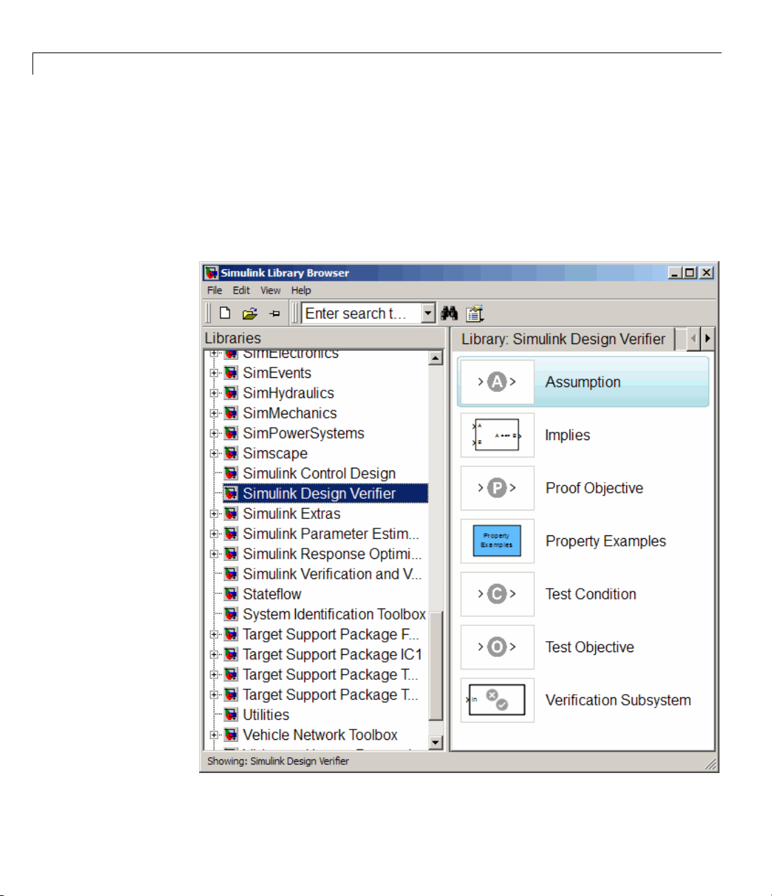
To open the Simulin k Design Verifier block library, type
MATLAB prompt to display the Simulink Library Browser, and then select
the S imulink Design Verifier entry in the contents tree.
simulink at the
1-4
Page 21
Starting the Simulink®Design Verifier™ Software
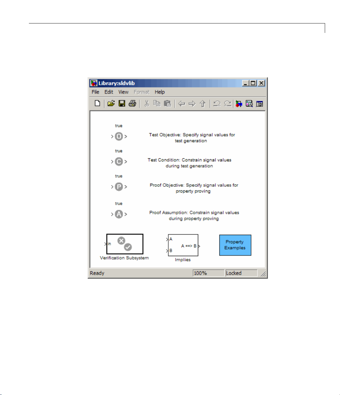
Alternatively, type sldvlib attheMATLABprompttodisplaytheSimulink
Design Verifier library.
1-5
Page 22

1 Getting Started
Analyzing a Model
In this section...
“About This Demo” on page 1-6
“Opening the M odel” on page 1-6
“Generating Test Cases” on page 1-7
“Combining Test Cases” on page 1-23
About This Demo
The following sections describe a demo model, Cruise Control Test Ge neration.
This demo illustrates how to use the Simulink Design Verifier software to
generate test cas es that achieve complete model coverage. Through this
demo, you learn how to analyze models with the Simulink Design Verifier
software and interpret the results.
1-6
Opening the Model
To open the Cruise Control Test Generation model, enter
sldvdemo_cruise_control at the MATLAB prompt.
The Cruise Control Test Generation model opens.
Page 23

Analyzing a Model
Generating Test Cases
• “Running the Analysis” on page 1-8
1-7
Page 24

1 Getting Started
• “Exploring the Test Harness” on page 1-10
®
• “Interpreting the Simulink
Design Verifier HTML Report” on page 1-15
Running the Analysis
To generate test cases for the C ruise Control Test Generation model, open the
model window and double-click the block labeled Run.
The Simulink Design Verifier softwar e begins analyzing the m odel to generate
test cases. During its analysis, thesoftwaredisplaysalogwindow.
1-8
Page 25

Analyzing a Model
The log window updates you on the progress of the Simulink Design Verifier
software as it analyzes the model.
1-9
Page 26

1 Getting Started
Note If you need to terminate an analysis while it is running, click Stop.
The software asks you if you want to produce results. If you click Yes,the
software creates the data file and report based on the results achieved so far.
The names of those files appear in the log window.
When the Simulink Design Verifier so ftware completes its analysis, it opens:
• Test harness model:
• Signal Builder dialog box containing the test-case signals
• HTML report containing the analysis results:
sldvdemo_cruise_control_report.html
The sections that follow describe the test harness, the Signal Builder data,
and the HTML report in detail.
sldvdemo_cruise_control_harness.mdl
Exploring the Test Harness
The Simulink Design Verifier software creates a test harness model w hen
it completes its analysis. The test harness for the Cruise Control Test
Generation model appears as shown in the following figure.
1-10
Page 27

Analyzing a Model
1 The block labeled Test Case Explanation is a DocBlock block that
documents the generated test cases. Double-click the Test Case
Explanationblocktoviewadescriptionofeachtestcaseintermsofthe
objectives that the test case satisfies.
1-11
Page 28

1 Getting Started
1-12
2 The block labeled Test Unit is a Subsystem blo ck that contains a copy of
the original model the software analyzed. Double-click the Test Unit block
to view its contents and confirm that it is a copy of the Cruise Control
Test Generation model.
Page 29

Analyzing a Model
3 The block labeled Inputs is a Signal Builder block that contains the
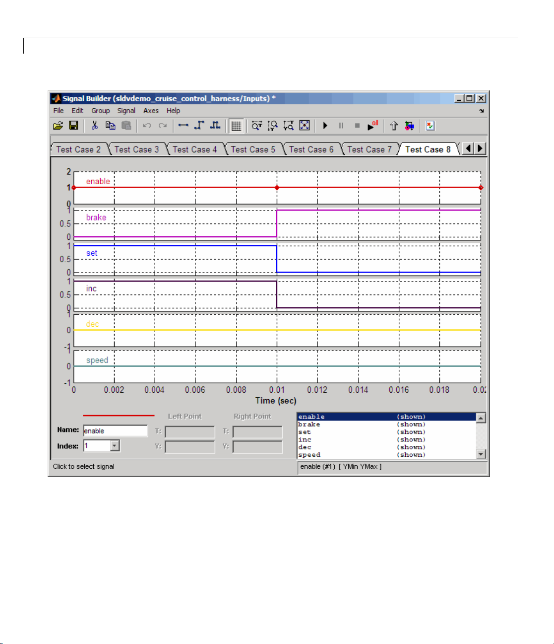
generated test case signals. Double-click the Inputs block to open the
Signal Builder dialog box and view the 10 test case signals.
4 In the Signal Builder dialog box, click the right-facing arrow next to the
test case tabs
to find the Test Case 8 tab.
5 Click the Test
Case 8 tab to display the signal values for Test Case 8.
1-13
Page 30
1 Getting Started
1-14
In Test Case 8 at 0.1 seconds:
• The enable signal remains 1.
• The brake signal transitions from 0 to 1.
• The inc and set signals transition from 1 to 0.
Page 31

Analyzing a Model
• The dec and s pee d signals remain 0.
This group of signals achieves the test objectives described in the Test
Case Explanation block.
6 To confirm that the Simulink Design Verifier softw are achieved complete
model coverage, simulate the test harness using all the test cases. In the
Signal Builder dialog box, click the Run all and produce coverage
button
.
The Simulink softw are simulates the test harn e ss using all the test cases,
while the Simulink Verification and Validation software collects model
coverage information and displays a coverage report with the following
summary.
The coverage report indicates the Simulink Design Verifier software
generated tes t cases that achieve complete coverage for the Cruise Control
Test Generation model.
Interpreting the Simulink Design Verifier HTML Repor t
The Simulink Design Verifier software creates an HTML report that
summarizes its analysis results.
If the report is not open in a Web Browser window, open it now. The path
name is:
1-15
Page 32
1 Getting Started
matlabroot/sldv_output/sldvdemo_cruise_control/sldvdemo_cruise_control_report.html
Note The log window contains the exact path name for the HTML report.
The HTML report includes the following chapters.
Each the following sections for a description of each report chapter:
1-16
• “Summary” on page 1-16
• “Analysis Information” on page 1-17
• “Test Objectives Status” on page 1-19
• “Model Items” on page 1-21
• “Test Cases” on page 1-22
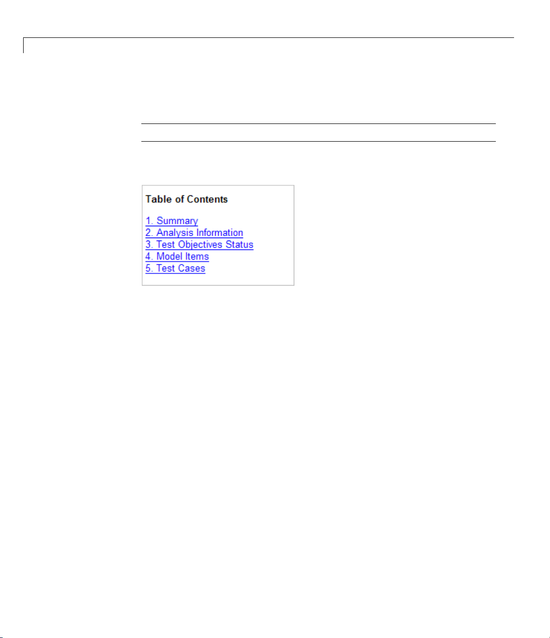
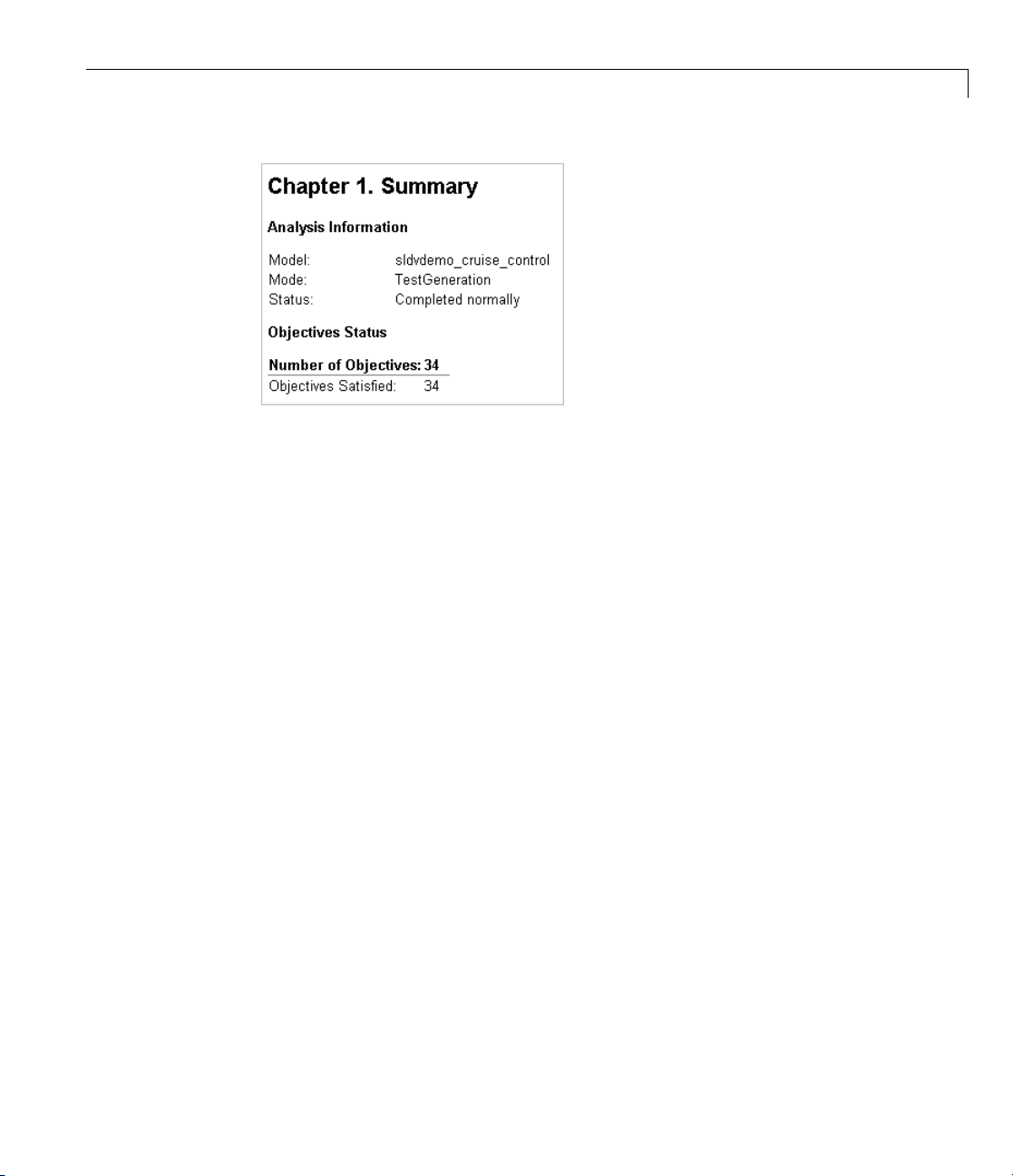
Summary. In the Table of Contents,clickSummary to display the
Summary chapter, which includes the following information:
• Name of the model
• Mode of the analysis (test generation or property proving)
• Status of the analysis
• Number of objectives satisfied
Page 33
Analyzing a Model
Analysis Information. In the Table of Contents,clickAnalysis
Information to display information about the analyzed model and the
analysis options.
1-17
Page 34

1 Getting Started
1-18
Page 35

Analyzing a Model
Test Objective s Status. In the Table of Contents,clickTest Objectives
Status to display a table of satisfied objectives. The following figure shows a
partial list of the objectives satisfied in the Cruise Control Test Generation
model.
The Obje c tive s Satisfied table lists the following information for the model:
• # — Objective number.
• Type — Objective type.
• Model Item — Element in the model for which the objective was tested.
Click this link to display the model with this element highlighted.
• Description — Description of the objective.
• Test case — Test case that achieves the objective. Click this link to get
more information about that test case.
1-19
Page 36

1 Getting Started
In the row for objective 17, click the test case number (8)todisplaymore
information about test case 8 in the report’s Test Cases chapter.
1-20
In this example, T est Case 8 satisfies 2 m odel coverage objectives. The
following signal values achieve the objectives listed in the Objectives column
of the table:
• Theenablesignalremains1.
• The brake signal transitions from 0 to 1 at 0.1 seconds.
Page 37

Analyzing a Model
• The inc and set signals transition from 1 to 0 at 0.1 seconds.
• The dec and speed signals remain 0.
This information matches what you see in the test harness model. Specifically,
the Inputs block in the test harness depicts identical signal values for Test
Case 8, and the Test Case Explanation block lists 2 objectives that Test Case
8 achieves (see “Exploring the Test Harness” on page 1-10).
Model Items. In the Table of Contents,clickModel Items to see detailed
information about each item in the model that defines coverage objectives.
This table includes the status of the objective at the end of the analysis. Click
the links in the table to get detailed information about the satisfied objectives.
1-21
Page 38

1 Getting Started
1-22
Test Cases. In the Table of Contents,clickTest Cases to display detailed
information about each generated test case, including:
• Length of time to execute the test case
• Number of objectives satisfied
Page 39

Analyzing a Model
• Detailed information about the satisfied objectives
• Input data
See the section fo r Test Case 8 in “Test Ob jectives Status” on page 1-19
Combining Test Cases
Ifyouprefertoreviewresultsthatarecombined into a smaller number of test
cases, set the Test suite optimization parameter to
When you use the
Long test cases optimization, the analysis generates
fewer, but longer, test cases that each satisfy multiple test objectives. This
optimization creates a more efficient analysis and easier-to-review results.
Long test cases.
Open the
Long test cases optimization:
1 Select Tools > Design Verifier > Options.
2 In the Select tree on the left side of th e Configuration Parameters dialog
sldvdemo_cruise_control model and rerun the analysis with the
box, in the Design Verifier category, select Test Generation.
3 Set the Test suite optimization parameter to Long test cases.
4 Click Apply and OK to close the Configuration Parameters dialog box.
5 In the sldvdemo_cruise_control model, double-click the blo ck labeled
Run.
The Signal Builder dialog box now contains one test case instead of ten test
cases.
1-23
Page 40

1 Getting Started
1-24
This HTM L report contains one section describing Test Case 1.
Page 41

Analyzing a Model
1-25
Page 42

1 Getting Started
Analyzing a Subsystem
In addition to analyzing a model, you can analyze a subsystem within a
model. This techn ique is good for large models, where you want to review the
analysis in smaller, manageable reports.
This example analyzes the Controller subsystem in the
sldvdemo_cruise_control model from “Analyzing a Model” on
page 1-6.
1 Open the demo model:
sldvdemo_cruise_control
2 Right-click the Controller subsystem, and select Design Verifier > Enable
“Treat as atomic unit” to analyze.
The Function Block Parameters dialog box for the Controller subsystem
opens.
1-26
3 Select Tr
An atomic subsystem executes as a unit relative to the parent model;
subsystem b lock execution does not interleave with parent block executio n .
This makes it possible to extract subsystems for use as standalone models.
You must set the Treat as atomic unit parameter to analyze a subsystem
with the Simulink Design Verifier software.
eat as atomic unit.
Page 43

Analyzing a Subsystem
After you set the parameter, other opt ions become available, but you can
ignore them.
4 Click Apply and OK to close the dialog box.
ct File > Save As and save the Cruise Control Test Generation model
5 Sele
ranewname.
unde
6 To start the subsystem analysis and generate test cases, right-click the
Controller subsystem, and select Design Verifier > Generate Tests for
Subsystem.
1-27
Page 44

1 Getting Started
1-28
7 The Simulink Design Verifier software creates and opens the following
output. Except for the new model, all of these correspond to the model
analysis output:
• A new model containing just the Controller subsystem:
• Test harness model: Controller_harness.mdl
• Signal Builder dialog box containing the test-case signals
• HTML report containing the analysis results:
8 Revi
ew the results of the subsystem analysis (harness model and HTML
rt) and compare them to the results of the full-model analysis described
repo
Analyzing a Model” on page 1-6.
in “
• The
subsystem analysis analyzes the Controller as a standalone model.
Controller_report.htm
Controller.mdl
Page 45

Analyzing a Subsystem
• The Controller subsystem contains all the test objectives in the Cruise
Control Test G eneration model, so both a nalyses generate the same
test cases.
1-29
Page 46

1 Getting Started
Basic Workflow for Using the Simulink Design Verifier
Software
The Simulink Design Verifier User’s Guide is organized on the basis of
workflow that you follow when generating tests for your model or proving
its properties. This workflow is described in the following steps, which cite
locations in the documentation that you can refer to for more information:
Step
1
2
3
4
5
Action
Check the compatibility of your model. Chapter 3, “Ensuring Compatibility with the
Optionally, prepare your model for
analysis.
Set Simulink Design Verifier options. Chapter 6, “Configuring Simulink
Generate test cases for your model or
prove its properties.
Interpret the results.
See...
Simulink
Chapter 4, “Working with Block
Replacements”
Chapter 5, “Specifying Parameter
Configurations”
Verifier Options”
Chapter 7, “Generating Test Cases”
Chapter 10, “Proving Properties of a Model”
Chapter 11, “Reviewing the Results”
®
Design Verifier Software”
®
Design
1-30
Page 47

Learning More
In this section...
“Next Step” on page 1-31
“Product Help” on page 1-31
“The MathWorks Online” on page 1-32
Next Step
To begin learning how to use the Simulink Design Verifier software, s ee
Chapter 3, “Ensuring Compatibility with the Simulink
Software”. Also see the following topics to continue your exploration of the
software:
®
Design Verifier
Learning More
For...
Exercise that walks you through the
process of generating test cases for
a model
se that walks you through the
Exerci
s of proving a model property
proces
Produ
More i
desktop, click
For...
Lis
Tutorials Examples in Documentation
More product demonstrations
What’s new in this product
ct Help
nformation is available with your product installation. In the MATLAB
for help, and click the product name in the Contents pane.
tofblocks
See...
“Generating Test Cases for a Model”
on page 7-5
“Proving Properties in a Model” on
page 10-5
..
See.
cks — Alphabetical List
Blo
Simulink Design Verifier Demos
Release Notes
1-31
Page 48

1 Getting Started
The MathWorks On
Point your brows
and support at
http://www.mathworks.com/products/sldesignverifier/
er to the MathWorks Web site for additional information
line
1-32
Page 49

How the Simulink Design
Verifier Software Works
• “Analyzing a Model with Simulink®Design Verifier Software” on page 2-2
• “Analyzing a Simple Model” on page 2-3
• “Short-Circuiting Logic Blocks” on page 2-5
• “Analyzing Large Models” on page 2-6
• “Handling Incompatibilities with Automatic Stubbing” on page 2-7
2
• “Approximations” on page 2-15
Page 50

2 How the Simulink
®
Design Verifier™ Software Works
Analyzing a Model with Simulink Design Verifier Software
Simulink Design Verifier software is an efficient analysis tool that explores
the simulation behavior of a Simulink model. It searches the possible values
of model inputs and block parameters to find a simulation that satisfies test
objectives. The software also proves model properties and generates examples
of violations.
Such analysis always begins with the initial configuration of the model
and can span an arbitrary number of time steps. Generally, there is an
infinite number of paths through the model because the values of inputs are
independent from one time step to th e next, and there is no fixed limit to the
number of time steps.
Ifthesoftwarefindsnowaytoreduce the search space, it would continue
its analysis indef in i t ely. Thus, the software limits the analysis by tracking
the persistent information in the model such as discrete states, data-store
memories, and persistent variables.
2-2
After an analysis explores all possible inputs and parameters from all possible
configurations, the results equal those of a complete search of every possible
infinite sequence of inputs parameters.
Page 51

Analyzing a Simple Model
This simple Simulink model includes two Logical Operator blocks and a
Memory block.
The persistent information in this model is limited to the Boolean value of
the Memory block. The input to the model is a single Boolean value. The
following table describes the complete behavior of the model, including the
behavior that would result from an arbitrarily long sequence of inputs.
Analyzing a Simple Model
#
Input Memory
Value
1
false false false false
true
2
3
false
4 true true
Suppose you want to generate test cases that result in a true output; this goal
is your test objective. If you run the Simulink D esign Verifier software to
generate test cases that result in a true output, the software searches this
table to see if such a scenario is possible.
After the Simulink Design Verifier software discovers a configuration that
satisfies the test objective (in this case, when both the input and the Memory
block output are true), it needs to find a path to reach this configuration from
false
true true
Output of XOR
Block = Next
Memory Value
true
false
Output of AND
Block
false
false
true
2-3
Page 52

2 How the Simulink
®
Design Verifier™ Software Works
the initial conditions. If the initial memory value is true, the test case only
needs to be a single time step (row 4) where the input was true.
If the initial m emory value is false (the default), the test case must force the
memoryvaluetobetrue.Inthisexample,thepathrequirestwosteps:
1 The input value is true and the memory value is false (row 2). Thus, the
output of the XOR block is true, making the memory value true.
2 Now that the input value and memory value are both true (row 4), the
output is true, so the analysis achieves the specified test objective.
An infinite number o f test cases can cause the output to be true, and
regardless of the state value, the output can be held false for an arbitrary time
before making it true. When the Simulink Design Verifier software searches,
it returns the first test case it encounters that satisfies the objective. This
case is invariably the simulation with the fewest tim e steps. Sometimes you
may find this result undesirable because it is unrealistic or does not satisfy
some other test requirement.
2-4
Thesamebasicprinciplesfromthisexample apply to property proving and
test case generation. During test case generation, option parameters explicitly
specify the search criteria. For e xample, you can specify that Simulink Design
Verifier software find paths for all outputs or find only those paths that make
where the output is true.
During property proving, you specify a functional requirement, or p roperty,
that you want the Simulink Design Verifier software to prove, for example,
that the output is always true. If the search completes without finding
a path that violates the property, the proof of that property completes
successfully. If the software finds a path where the output is false, it creates a
counterexample that causestheoutputtobefalse.
Page 53

Short-Circuiting Logic Blocks
When the Simulink Design Verifier software p erforms an analysis, if possible,
the software short-circuits logic blocks. When the previous inputs alone
determine the block output, the analysis ignores any remaining block inputs.
For e xample, if the first input to a Logical Operator block whose Operator
parameter specifies
inputs.
Consider the following example model, with the Model coverage objectives
parameter set to
AND is false, the analysis ignores the v alues of the other
Condition Decision.
Short-Circuiting Logic Blocks
When the Simulink Design Verifier software analyzes this model for Condition
Decision coverage, the analysis can only satisfy five of six objectives for the
Logical Operator block inputs. The software cannot generate a test case for
when the third input to the Logical Operator block is false. If the second input
isfalse,thethirdinputisfalse,butthesoftwareignoresthethirdinputdueto
the short-circuiting. If the second input is true, the third input is never false.
2-5
Page 54

2 How the Simulink
®
Design Verifier™ Software Works
Analyzing Large Models
In larger, more complicated models, the Simulink Design Verifier software
uses m athematical techniques to simplify the analysis:
• It identifies portions of the model that do not affect the desired objectives.
• It discovers relations hips within the model that reduce the complexity of
the search.
• It reuses intermediate results from one objective to another.
In this way, the problem is reduced to a search though the logical values that
describe your model.
For detailed information about analyzing large models, see Chapter 12,
“Analyzing Large Models and Improving Performance”.
2-6
Page 55

Handling Incompatibilities with Automatic Stubb ing
Handling Incompatibilities with Automatic Stubbing
In this section...
“What Is Automatic Stubbing?” on page 2-7
“Analyzing a Model Using Automatic Stubbing” on page 2-7
What Is Automatic Stubbing?
Automatic stubbing allows you to run a test case generation or
property-proving analysis on a model that contains elements that the
Simulink Design Verifier software does not support.
When you enable automatic stubbing option, the software considers only
the interface of the unsupported elements, not their actual behavior. This
technique allows the software to complete the analysis. However, the analysis
may achieve only partial results if any of the unsupported model elements
affect the simulation outcome.
Analyzing a Model Using Automatic Stubbing
This section describes a workflow for using automatic stubbing, using a
simple Simulink model (
• “Checking Model Compatibility” on page 2-8
• “Turning On Automatic Stubbing” on page 2-11
• “Reviewing the Results” on page 2-13
• “Achieving Complete Results” on page 2-14
The
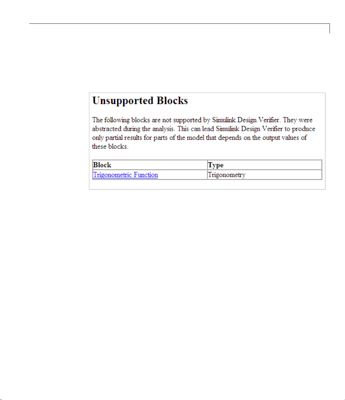
t1 model contains a Trigonometric Function block, which is not
compatible with the Simulink Design Verifier software.
t1)asanexample.
2-7
Page 56

2 How the Simulink
®
Design Verifier™ Software Works
2-8
Checking Model Compatibility
From the Model Editor, there are two ways to check whether a model is
compatible with the Simulink Design Verifier software:
• Run the Simulink De sig n Ve rif ier compatibility check by selecting
Tools > Design Verifier > Check Model C ompatibility.
Page 57

Handling Incompatibilities with Automatic Stubb ing
• Select the analysis that you want:
- Tools > Design Verifier > Generate Tests
- Tools > Design Verifier > Prove Properties
Thesoftwarefirstchecksthecompatibility of the model. If the model itself
is incompatible, for example, if it uses a variable-step solver, the analysis
cannot continue.
If it finds incompatible elements in the model, the software stops and asks
if you want to turn on automatic stubbing.
2-9
Page 58

2 How the Simulink
®
Design Verifier™ Software Works
2-10
an:
You c
- Save
- Con
- Ter
the log file.
tinue the analysis.
minate the analysis.
Page 59

Handling Incompatibilities with Automatic Stubb ing
The Simulatio n Diagnostics Viewer is also displayed, listing the
incompatibilities. (For more information about this dialog box, see
“Simulation Diagnostics Viewer” in the Simulink User’s Guide.)
Turning On Automatic Stubbing
There are two ways to turn on automatic stubbing:
• If you have not turned on automatic stubbing and the analysis finds at
least one incompatibility, the analysis stops and asks if you want to turn on
automatic stubbing. Click Continue to proceed with the analysis.
2-11
Page 60

2 How the Simulink
®
Design Verifier™ Software Works
• Before starting the analysis, in the Configuration Parameters dialog
box, on the main Design Verifier pane, select Automatic stubbing of
unsupportedblockandfunctions. Whenyouruntheanalysis,youare
notified that stubbing is turned on and the analysis continues.
2-12
Page 61
Handling Incompatibilities with Automatic Stubb ing
Reviewing the Results
If you ran the analysis with automatic stubbing enabled, make sure to review
the results. In this report, you see a table of unsupported blocks that the
software encountered.
The Summary report for the t1 example model shows that one objective was
satisfied without generating a test case. The software cannot generate the
test case because it does not understand the operation of the Trigonometric
Function block.
2-13
Page 62

2 How the Simulink
®
Design Verifier™ Software Works
Achieving Complete Results
If your analysis does not achieve complete results because of the stubbing,
you can define custom block replacements to give a more precise definition
of the unsupported blocks. For more information:
• “Defining Custom Block Replacements” on p age 4-8.
• Enter
echodemo sldvdemo_blockreplacement_unsupportedblocks
to step through the “Block Replacements for Unsupported Models” demo.
2-14
Page 63

Approximations
In this section...
“Approximations During Model Analysis” on page 2-15
“Types of Approximations” on page 2-15
“Converting Floating-Point Arithmetic to Rational-Number Arithmetic ”
on page 2-15
“Linearizing 2-D Lookup Tables” on page 2-16
“Unrolling While Loops” on page 2-17
“Ensuring the Validity of the Analysis” on page 2-17
Approximations During Model Analysis
The Simulink Design Verifier software attempts to generate inputs and
parameters to achieve test and proof objectives. However, there could be an
infinitenumberofvaluesforthesoftwaretosearch. Tocreatereasonable
limits on the analysis, the software perform s approximations to simplify
the analysis. The software records any approximations it performed in the
Analysis Information chapter of the Simulink Design Verifier HTML report.
Approximations
Types of Approximations
Simulink Design Verifier software performs three types of approximations
when it analyzes a model:
• “Converting Floating-Point Arithmetic to Ra tional-Number Arithmetic ”
on page 2-15
• “Linearizing 2-D Lookup Tables” on page 2-16
• “Unrolling While Loops” on page 2-17
Converting Floating-Point Arithmetic to
Rational-Number Arithmetic
The Simulink Design Verifier software simplifies the linear arithmetic
of floating-point numbers by approximating them with infinite-precision
rational numbers. The software discovers how the logical relationships
2-15
Page 64

2 How the Simulink
®
Design Verifier™ Software Works
between these values affects the proof and test objectives. This analysis
enables the software to support supervisory logic that is commonly found in
embedded controls designs.
If your model contains floating-point values in the signals, input values, or
block parameters, the Simulink Design Verifier software converts those
values to rational numbers before performing its analysis.
Note As a result of these approximations, Simulink Design Verifier software
does no t consider the effect of round-off error, or the upper and lower bounds
of floating-point numbers.
Linearizing 2-D Lookup Tables
The S imulink Design Verifier software does not support n on li near ar ithmetic.
If your model contains any Lookup Table (2-D) blocks, or Lookup Table (n-D)
blocks where n = 2, with all of the following characteristics, the software
approximates nonlinear 2-D interpolation with linear interpolation by fitting
planes to each interpolation interval.
2-16
Block Characteristics
Lookup Table (2-D)
block
• Lookup method parameter is
Interpolation-Extrapolation or
Interpolation-Use End Values
• The input and output signals both have the
floating-point data type
Lookup Table (n-D)
block, n =2:
• Interpolation method parameter is
• Extrapolation method parameter is None -
or Linear
Clip
• The input and output signals both have the
floating-point data type
Linear
Page 65

Approximations
Unrolling While
If your model or a
Simulink Design
loop to exit. To
times. If the so
it sets the num
you are perfor
Ensuring the
The Simulink
performed i
descriptio
on page 11-20.
Review the
Evaluate y
software
In rare ca
test obj
example
achieve
might pr
n of the contents of this chapter, see “Analysis Information Chapter”
our model to identify which blocks or subsystems caused the
to perform th e approximations.
ses, an approximation can result in test cases that fail to achieve
ectives, or counterexamples that fail to falsify proof objectives. For
, suppose the software generates a test case signal that should
an objectiv e by excee ding a thre shold; a floating-point round-off error
event that signal from attaining the threshold value.
ny Stateflow chart in your model contains a
Verifier software tries to find a bound that allows the
find a bound, it unrolls the
ftware does not find a bound for a test case generation analysis,
ber of loop iterations to three for the purpose of the analysis. If
ming a property-proving analysis, the analysis terminates.
Validity of the Analysis
Design Verifier software records all approximations it
n the Analysis Information chapter of the HTML report. (For a
)
analysis results carefully when thesoftwareusesapproximations.
Loops
while loop, the
while
while loop and executes it three
2-17
Page 66

2 How the Simulink
®
Design Verifier™ Software Works
2-18
Page 67

Ensuring Compatibility
with the Simulink Design
Verifier Software
• “Checking Model Compatibility” on page 3-2
• “Unsupported Simulink Software Features” on page 3-9
• “Unsupported Stateflow Software Features” on page 3-13
3
• “Support Limitations for the Embedded MATLAB Subset” on page 3-15
• “Fixed-Point Support Limitations” on page 3-18
Page 68

3 Ensuring Compatibility with the Simulink
®
Design Verifier™ Software
Checking Model Compatibility
The Simulink Design Verifier software supports a broad range of Simulink
and Stateflow software features. However, there are features that the product
does not support. Therefore, avoid using particular features in models that
you plan to analyze with the Simulink Design Verifier software.
The Simulink Design Verifier software automatically checks the compatibility
of your model before it begins a test-generation or property-pro ving analysis.
In addition, you can run the same check before you start the analysis. To run
this check, in the model window, select Tools > Design Verifier > Check
Model Compatibility.
3-2
Page 69

Checking Model Compatibility
natively, you can use the
Alter
ker programmatically at the command line or in a MA TLAB program.
chec
ore information, see the
For m
e are three outcomes of a compatibility check:
Ther
del Is Compatible” on page 3-4
• “Mo
del Is Incompatible” on page 3-4
• “Mo
sldvcompat function to run the compatibility
sldvcompat reference page.
3-3
Page 70

3 Ensuring Compatibility with the Simulink
• “Some Model O bjects Are Incompatible” on page 3-6
Model Is Compatible
In the log window, you see if your model is compatible with the Simulink
Design Verifier software.
®
Design Verifier™ Software
3-4
Model Is Incompatible
If the model itself is incompatible with the software, for example, if it uses
a variable-step solver, you see two dialog boxes:
• Simulink Design Verifier log
Page 71

Checking Model Compatibility
• Simulation Diagnostics Viewer. Use the informa t ion in this dialog box to
identify and correct theincompatibility.
3-5
Page 72

3 Ensuring Compatibility with the Simulink
®
Design Verifier™ Software
3-6
Note For more information about this dialog box, see “Simulation
Diagnostics Viewer” i n the Simulink User’s Guide.
Some Model Objects Are Incompatible
If at least one object in the model is incompatible, a message appears in
the Simulink Design Verifier log window. If you have turned on automatic
stubbing, the analysis proceeds.
Page 73

Checking Model Compatibility
If you have not turned on automatic stubbing, the analysis stops. You see a
query asking if you want to turn it on so that the analysis can proceed.
3-7
Page 74

3 Ensuring Compatibility with the Simulink
®
Design Verifier™ Software
3-8
Note
Inc
For instructions on how to use automatic stubbing, see “Handling
ompatibilities with Automatic Stubbing” on page 2-7.
Page 75

Unsupported Simulink Software Features
In this section...
“Simulink Software Features Not Supported” on page 3-9
“Simulink Block Support Limitat ions” on page 3-11
“Limitations of Support for Model Reference” on page 3-11
Simulink Software Features Not Suppor ted
The Simulink Design Verifier software does not support the following
Simulink software features. Avoid using these unsupported features in
models that you analyze w ith the Simulink Design Verifier software.
Unsupported Simulink®Software Features
Not Supported
Variable-step solvers
Callback functions The Simulink Design Verifier software does not
Complex signals The Simulink Design Verifier software supports only
Description
The Simulink Design Verifier software supports
only f ix e d -ste p solvers. (See “C hoosing a Fixed-Step
Solver” in the Simulink User’s Guide.)
execute model callback functions during the
analysis. As a result, if a callback function changes
any m odel parameters or workspace variables, the
analysis does not reflect those changes.
Callbacks called prior to analysis, such as the
PreLoadFcn or Po stL oadFcn model callbacks, are
fully supported.
real signals. (For contrast, see “Complex Signals” in
Simulink User’s Guide.)
3-9
Page 76

3 Ensuring Compatibility with the Simulink
®
Design Verifier™ Software
Not Supported
Variable-size signals
Multiword
fixed-point data
types
Signals with nonzero
sample tim e offset
Nonzero start times
Description
The Simulink Design Verifier software does not
support variable-size signals. A variable-size signal
is a signal whose size (number of elements in a
dimension), in addition to its values, can change
during model execution.
For more information, see “Working with
Variable-Size Signals” in Simulink User’s Guide.
The Simulink Design Verifier software does not
support multiword fixed-point data types.
The Simulink Design Verifier software does not
support models with signals that have nonz ero
sample time offsets.
Although Simulink allows you to specify a nonzero
simulation start time, the Simulink Desig n Verifier
software generates signal data that begins only at
zero. If your model specifies a nonzero start time:
• If you do not select the Reference input model
in generated harness parameter (the default),
the harness model is a subsystem. The software
sets the start time of the harness model to 1 and
continues the analysis.
3-10
Models with no
output ports
• If you select the Reference input model in
generated harness parameter, a Model block
references the harness model. The Simulink
Design Verifier software cannot change the start
time of the harness model, so the analysis stops
and you see a recommendation to set the Start
time parameter to 0.
The Simulink Design Verifier software only s upports
models that have one or more output ports.
Page 77

Unsupported Simulink®Software Features
Simulink Block S
The Simulink D es
Simulink blocks
blocks. It does
If your model c
stubbing, whi
not their beha
simulation o
about automa
Stubbing” on
To guarante
you analyze
Similarly
software r
“Simulin
Limitati
The Simu
the foll
one or mo
, specify only the block parameters that the Simulink Design Verifier
ecognizes for blocks that it partially supports. See Chapter 16,
k Block Support”.
onsofSupportforModelReference
link Design Verifier software supports the Model block, but with
owing limitations. The software cannot analyze a model that contains
re Model blocks if:
ign Verifier software provides various levels of support for
. The software either fully or partially supports pa rticular
not support other blocks.
ontains unsupported blocks, you can turn on automatic
ch considers the interface of the unsupported blocks, but
vior. However, if any of the unsupported blocks affect the
utcome, the analysis may achieve only partial results. For details
tic stubbing, see “Handling Incompatibilities with Automatic
page 2-7.
e 100% coverage, avoid using unsupported blocks in models that
with the Simulink Design Verifier software.
upport Limitations
• Simuli
models
This f
being
more i
User’
• The p
ne of the following model parameters to
set o
- Diag
- Dia
sig
nk Design Verifier software doe s not support protected referenced
. Protected referenced models are encoded to obscure their contents.
eature allows third parties to use the referenced model without
able to view the intellectual property that makes up the model. For
nformation, see “Protecting Referenced Models” in the Simulink
s Guide.
arent model or any of the referenced models gives an error when you
Error:
nostics > Connectivity > Element name mismatch
gnostics > Connectivity > Mux blocks used to create bus
nals
3-11
Page 78

3 Ensuring Compatibility with the Simulink
You can use the Element name mismatch diagnostic along with bus
objects to ensure that your model meets bus element naming requirements
imposed by some blocks.
If your model contains Mux blocks that create bus signals, refer to “Tips” in
“Mux blocks used to create bus signals” to resolve this problem.
• A referenced model references a variable in its workspace that is either
defined in its ow n workspace or in the base MATLA B workspace. It is also
defined with the same name in the parent model’s workspace. Rename
the variable used by the referenced model to a unique name so that you
can analyze the model.
Exception: If the parent model and a referenced model both define an
instance of a
same name, the software can analyze the model.
• Any of the models in the model reference hierarchy have algebraic loops
that algebraic loop minimization cannot eliminate. If you encounter
this limitation, set the Minimize algebraic loop parameter on the
Diagnostics pane of the Configuration Parameters dialog box to Error.
Then, update the model to identify the location of algebraic loop in the
model.
®
Design Verifier™ Software
Simulink.Signal object used as local data storage with the
3-12
To eliminate this problem so that the software can analyze the model,
break any algebraic loops with Unit Delay blocks to ensure that the
execution order is predictable.
For more information, see “Algebraic Loops” in the Simulink User’s Guide.
Page 79

Unsupported Stateflow®Software Features
Unsupported Stateflow Software Features
The Simulink Design Verifier software does not support the following
Stateflow software features. Avoid using these unsupported features in
models that you analyze w ith the Simulink Design Verifier software.
Not Supported
ml namespace operator,
ml function, ml
expressions
Description
The Simulink Design Verifier software does
not support calls to MATLAB functions or
access to MATLAB workspace variables, which
the Stateflow software allows. (See “Using
MATLAB Functions and Data in Actions” in the
Stateflow and Stateflow
®
Coder™ User’s Guide.)
C math functions The Simulink Design Verifier software supports
calls to the following C math functions:
ceil, fabs, floor, fmod, labs, ldexp,andpow
abs,
(only for an integer exponent).
The software does not support calls to other
C math functions that the Stateflow software
allows. Turning on auto matic stubbing causes
the software to eliminate these functions during
the analysis. For details about automatic
stubbing, see “Handling Incompatibilities with
Automatic Stubbing” on page 2-7.
For information about C math functions in
Stateflow, see “Calling C Functions in Actions”
in the Stateflow and Stateflow Coder User’s
Guide.
3-13
Page 80

3 Ensuring Compatibility with the Simulink
®
Design Verifier™ Software
Not Supported
Recursion
Description
The Simulink Design Verifier software does
not support recursive functions, which the
Stateflow software allows you to implement
using graphical functions. (See “Using
Graphical Functions to Extend Actions” in the
Stateflow and Stateflow Coder User’s Guide.)
Also, the Simulink Design Verifier software
does not support recursion that the Stateflow
software allows you to implement using a
combination of event broadcasts and function
calls.
Custom C or C++ code The Simulink Design Verifier software does
not support custom C or C++ code, which the
Stateflow software allows. (See “Building
Targets” in the Stateflow and Stateflow Coder
User’s Guide.)
Machine-parented data
The Simulink Design Verifier software does not
support machine-parented data (i.e., defined at
the level of the Stateflow machine), which the
Stateflow software allows. (See “Defining Data”
in the Stateflow and Stateflow Coder User’s
Guide.)
3-14
Textual functions with
literal string arguments
The Simulink Design Verifier software does
not support literal string arguments to textual
functions in a Stateflow chart.
Page 81

Support Limitations for the Embedded MATLAB®Subset
Support Limitations for the Embedded MATLAB Subset
In this section...
“Unsupported Embedded MATLAB Subset Features” on page 3-15
“Limitations of Embedded MATLAB Library Function Support” on page
3-16
Unsupported Embedded MATLAB Subset Features
The Simulink Design Verifier software does not support the following features
of the Embedded MATLAB
Embedded MATLAB functions in the Stateflow software. Avoid using these
unsupported features in models that you analyze with the Simulink Design
Verifier software.
®
Function block in the Simulink software and
Not Supported
Complex numbers The Simulink Design Verifier software supports
Characters The Simulink Design Verifier software does
Description
only real numbers. The Embedded MATLAB
subset also supports complex numbers.
For more information, see “Working with
Complex N umbers” in the Embedded MATLAB
User’s Guide.
not support characters, which the Embedded
MATLAB subset allows.
For more information, see “Working with
Characters” in the Embedded MATLAB User’s
Guide.
3-15
Page 82

3 Ensuring Compatibility with the Simulink
®
Design Verifier™ Software
Not Supported
C functions The Simulink Design Verifier software does not
Extrinsic functions The Simulink Design Verifier software supports
Description
support calls to external C functions, which the
Embedded MATLAB subset allows.
For more information about the Embedded
MATLAB subset, see“Calling C/C++ Functions
from the Embedded MATLAB Subset” in the
Embedded MATLAB User’s Guide.
extrinsic functions only when they do not affect
the output of an Embedded MATLAB function.
For more information about calling extrinsic
functions, see “Calling MATLAB Functions” in
the Embedded MATLAB User’s Guide.
Limitations of Embedded MATLAB Library Function
Support
The Simulink Desig n Verifier software provides various levels of support for
Embedded MATLAB library functions. The software either fully or partially
supports particular functions. It does not support other functions.
3-16
If your model contains unsupported functions, you can turn on automatic
stubbing, which considers the interface of the unsupported functions, but
not their behavior. However, if any of the unsupported functions affect the
simulation outcome, the analysis may achieve only partial results. For details
about automatic stubbing, see “Handling Incompatibilities with Automatic
Stubbing” on page 2-7.
To guarantee 100% coverage, avoid using unsupported Embedded MATLAB
library functions in models that you analyze with the Simulink Design
Verifier software.
Avoid using unsupported Embedded MATLAB library functions in models
that you analyze with the Simulink Design Verifier software. See Chapter 17,
“Embedded MATLAB Subset Support” for a list of the Embedded MATLAB
Page 83

Support Limitations for the Embedded MATLAB®Subset
library functions for which the Simulink Design Verifier software provides
limited or no support.
3-17
Page 84

3 Ensuring Compatibility with the Simulink
®
Design Verifier™ Software
Fixed-Point Support Limitations
The Simulink Design Verifier software supports fixed-point data types in
models that it analyzes , with one exception. Parameter configurations do
not support fixed-point data types. For more information about configuring
Simulink D esign Verifier parameters, see Chapter 5, “Specifying Parameter
Configurations”.
For detailed information about these limitations, see “Tunable Expression
Limitations” in the Real-Time Workshop
®
User’s Guide.
3-18
Page 85

Working with Block
Replacements
• “About Block Replacements” on page 4-2
• “Built-In Block Replacements” on page 4-4
• “Template for Block Replacement Rules” on page 4-7
• “Defining Custom Block Replacements” on page 4-8
• “Executing Block Replacements” on page 4-17
4
Page 86

4 Working with Block Replacements
About Block Replacements
Using the Simulink D esign Verifier software, you can define rules to replace
blocks automatically in your model. For example, you can work around a
block that is incompatible with the software by creating a rule that replaces
an unsupported Simulink block in your model with a supported block that is
functionally equivalent. Or, you can customize blocks for analysis by creating
a rule that adds constraints or objectives to particular blocks in your model.
When performing block replacements, the software makes a copy of your
model a nd replaces blocks in the copy, without altering your original model.
In this way, you can easily customize a model for analysis.
The Simulink Design Verifier software replaces blocks automatically in a
model using:
• Libraries of replacement blocks
• Rules that define which blocks to replace and under what conditions
4-2
You replace any block with any built-in block, library block, or subsystem.
Block replacements are extensible, allowing you to define your own libraries
of replacement blocks and custom block replacement rules. Use this capability
if you need to:
• Work around an incompatibility, such as the presence of unsupported
blocks in your model.
• Customize a block for analysis, such as:
- Adding constraints to its input signals
- Adding objectives to its output signals
- Eliminating the contents of a subsystem or Model block to simplify your
analysis
Page 87

About Block Replacements
Note You can use automatic stubbing as an alternative to block replacements
in order to resolve incompatibilities. Automatic stubbing replaces unsupported
blocks with elements that have the same interface. For more information, see
“Handling Incom patibilities with Automatic Stubbing” on page 2-7.
4-3
Page 88

4 Working with Block Replacements
Built-In Block Replacements
The Simulink Design Verifier software provides a set of block replacement
rules and a corresponding library of replacement blocks. Use these built-in
block replacements when analyzing models. They serve as examples that you
can exam ine to learn how to create your own block replacements.
The following table lists the factory default block replacement rules, available
in the
implementations of each factory-default block replacement rule. Rules whose
file names end with
whose file names end with
Subsystem blocks.
matlabroot\toolbox\sldv\sldv\private folder. There are two
_normal.m replace blocks with Subsystem blocks. Rules
_configss.m replace blocks with Configurable
File Name
blkrep_rule_lookup_normal.m
blkrep_rule_lookup_configss.m
blkrep_rule_lookup2D_normal.m
blkrep_rule_lookup2D_configss.m
blkrep_rule_mpswitch2_normal.m
blkrep_rule_mpswitch2_configss.m
Descriptio
A rule that replaces Lookup Table blocks with
an implementation that includes test objectives
for each breakpoint and interval specified by the
Vector of input values parameter.
A rule that adds Test Condition/Proof Assumption
blocks to the input ports of Lookup Table (2-D)
blocks. Each Test Condition/Proof Assumption
block constrains signal values to the interval
specified by the corresponding breakpoint vector.
A rule that adds a Test Condition/Proof
Assumption block to the control input port of
Multiport Switch blocks whose Number of
inputs parameter is
Assumption block constrains signal values to the
interval [1, 2] ( or [0, 1] if the block uses zero-based
indexing).
n
2. The Test Condition/Proof
4-4
Page 89

Built-In Block Replacements
File Name
blkrep_rule_mpswitch3_normal.m
blkrep_rule_mpswitch3_configss.m
blkrep_rule_mpswitch4_normal.m
blkrep_rule_mpswitch4_configss.m
blkrep_rule_mpswitch5_normal.m
blkrep_rule_mpswitch5_configss.m
blkrep_rule_switch_normal.m
blkrep_rule_switch_configss.m
Description
A rule that adds a Test Condition/Proof
Assumption block to the control input port of
Multiport Switch blocks whose Number of
inputs parameter is
3. The Test Condition/Proof
Assumption block constrains signal values to the
interval [1, 3] ( or [0, 2] if the block uses zero-based
indexing).
A rule that adds a Test Condition/Proof
Assumption block to the control input port of
Multiport Switch blocks whose Number of
inputs parameter is
4. The Test Condition/Proof
Assumption block constrains signal values to the
interval [1, 4] ( or [0, 3] if the block uses zero-based
indexing).
A rule that adds a Test Condition/Proof
Assumption block to the control input port of
Multiport Switch blocks whose Number of
inputs parameter is
5. The Test Condition/Proof
Assumption block constrains signal values to the
interval [1, 5] ( or [0, 4] if the block uses zero-based
indexing).
A rule that replaces Switch blocks with an
implementation that includes test objectives,
requiring that each switch position be exercised
when the values of the first and third input ports
are different.
4-5
Page 90

4 Working with Block Replacements
File Name
blkrep_rule_selector
IndexVecPort_normal.m
blkrep_rule_selector
IndexVecPort_configss.m
blkrep_rule_selector
StartingIdxPort_normal.m
blkrep_rule_selector
StartingIdxPort_configss.m
The library of replacement blocks that corresponds to the factory default
rules is
matlabroot/toolbox/sldv/sldv/sldvblockreplacementlib.mdl
Description
A rule that adds a Test Condition/Proof
Assumption block to the index port of Selector
blocks whose Index Option parameter is
vector (port)
. The Test Condition/Proof
Index
Assumption block constrains signal values to an
interval whose endpoints are derived from the
values of the Selector block’s Inputportsizeand
Index mode parameters.
A rule that adds a Test Condition/Proof
Assumption block to the index port of Selector
blocks whose Index Option parameter
is
Starting index (port).TheTest
Condition/Proof Assumption block constrains
signal values to an interval whose endpoints are
derived from the v a lues of the Selector block’s
Input port size, Output size,andIndex mode
parameters.
4-6
Page 91

Template for Block Replacement Rules
To help you create block replacement rules, the Simulink Design Verifier
software provides an annotated template that contains a skeleton
implementation of the requisite callbacks:
matlabroot/toolbox/sldv/sldv/sldvblockreplacetemplate.m
To create a block replacement rule, makeacopyofthetemplateandeditthe
copy to implement the desired behaviorfortheruleyouarecreating. The
comments in the template provide hints about how to use each section. For a
tutorial on using the template to write custom block replacements rules, see
“Writing Block Replacement Rules” on page 4-9.
Template for Block Replacement Rules
4-7
Page 92

4 Working with Block Replacements
Defining Custom Block Replacements
In this section...
“Basic Workflow for Defining Custom Block Replacements” on page 4-8
“Specifying Replacement Blocks” on page 4-8
“Writing B lock Replacement Rules” on page 4-9
“Example: Replacing Multiport S witch Blocks” on page 4- 9
Basic Workflow for Defining Custom Block
Replacements
To replace certain blocks in your model in a way that the factory-default
block replacement rules do not handle, create custom block replacement rules
by completing the following tasks:
• “Specifying Replacement Blocks” on page 4-8
4-8
• “Writing Block Replacement Rules” on page 4-9
Specifying Replacement Blocks
A replacement block can be one of the built-in blocks in the Simulink model
library or a block in a user-created library.
In the Simulink Design Verifier software, replacement blocks have the
following restrictions:
• They must be built-in blocks or subsystems.
• They cannot be Model blocks, nor can they include any Model blocks.
Note A Model block cannot be a replacement block, but you can replace
Model blocks with built-in blocks or subsystems.
• They must reside in a block library that is available on your MATLAB
search path.
Page 93

Defining Custom Block Replacements
• If the replacement block is a subsystem, any Inport and Outport blocks
must have the default names (
After constructing your replacement block, write a custom block replace ment
rule.
In1 and Out1).
Writing Block Replacement Rules
Block replacement rules have the following restrictions:
• The function that represents a block replacement rule must include
particular callbacks. The MathWorks™ recommends that you use the block
replacement rule template as a starting point for writing a custom rule.
(See “Template for Block Replacement Rules” on page 4-7.)
• The function that represents a block replacement rule must be on the
MATLAB search path.
Example: Replacing Multiport Switch Blocks
• “Why Replace Multiport Switch Blocks?” on page 4-9
• “Creating the Library and Replacement Block” on page 4-10
• “Writing the Rule for the Replacement Block” on page 4-13
Why Replace Multiport Switch Blocks?
A Multiport Switch block has one control input port and one or more data
input ports; the default number of data inputs is 3.
4-9
Page 94

4 Working with Block Replacements
A model may have test objectives on some blocks whose output is directly or
indirectly connected to the Multiport Switch block. For example, a Saturation
block m ay send data to the control input port. In this case, the analysis may
create test cases that satisfy those objectives. However, those test cases may
create values that are out of range for the control input port, regardless of
whether the Multiport Switch block uses zero-based indexing or one-based
indexing. This causes the simulation to fail.
In this example, you create a rule to replace all Mult ip ort Switch blocks that
have two data inputs and do not use zero-based indexing. The replacement
block is a subsystem that has a T est Condition block that constrains the value
of the control input to 1 or 2, so that the analysis does not create out-of-range
data input values. This allows the analysis to satisfy the objectives o n blocks
that are connected to the control input port of the Multiport Switch block.
Creating the Library and Replacement Block
Create a user library and specify the replacement block as a masked
subsystem:
4-10
1 In the Simulink Library Browser, select File>New>Library.
2 In your library, create a subsys tem named myReplacementBlock to
represent your replacement block. It should look like the following graphic,
with several parameters set:
• In the Multiport Switch block, set the Number of data ports para m eter
to
2.
• In the Test Condition block, set the Values parameter to
{[1, 2]}.
Page 95

Defining Custom Block Replacements
3 To create a mask for your subsystem, select the subsystem, right-click, and
select Mask subsystem from the context menu.
Specify the following information in the Mask Editor:
• In the Parameters pane, click the Add button
parameter named
InputSameDT as shown.
to define a mask
This parameter replicates the behavior of the Require all data port
inputs to have the same data type parameter of the underlying
Multiport Switch block.
4-11
Page 96

4 Working with Block Replacements
4-12
Note When you create mask parameters that control the behavior
of parameters associated with their underlying blocks, specify actual
parameter names as dialog box variables in the Mask Editor. For
instance,
InputSameDT is the actual parameter name that controls the
Require all data port inputs to have the same data type parameter
of the Multiport Switch block; therefore, it specifies the name of the
dialog box v aria ble in this example.
• In the Initialization pane, in the Initialization commands field,
enter commands to specify that the subsystem inherit the
InputSameDT
parameter value of the top-level m odel:
maskInputSameDT = get_param(gcb,'InputSameDT');
blkName = sprintf('/Multiport\nSwitch');
targetBlock = [gcb, blkNam e];
set_param(targetBlock,'InputSameDT',maskInputSameDT);
Page 97

Defining Custom Block Replacements
4 Save your block library as custom_rule.mdl inafolderonyourMATLAB
search path.
Writing the Rule for the Replacement Block
To write a rule for the replacement block:
1 Open the block replacement rule template
matlabroot/toolbox/sldv/sldv/sldvblockreplacetemplate.m
2 Make a copy of the file and save it as custom_rule_switch.m in a folder on
your MATLAB search path.
Note Execute steps 3 through 11 for the copy of the template that you
saved.
3 To declare a function c ust om_rule_switch and modify its help, modify
the first few lines of the template:
function rule = custom_ru le_switch
%CUSTOM_RULE_SWITCH Custom block replacement rule for
%the Simulink Design Verif ier software
%
% This block replacement rule identifies Multiport
% Switch blocks whose "Number of inputs" parameter
% specifies '2' and "Use zero-based indexing" parameter
% specifies 'off'. It replaces such blocks with an
% implementa tion that includes a Test Condition block
% on the control input signal.
The function name must match its file name, without the .m extension. The
comments that follow the function declaration create help for this rule.
4 Specify the type of block that you want to replace in your model by
specifying its
example, change the
%% Target Block Type
BlockType parameter as the rule.blockType object. For this
rule.blockType object to 'MultiPortSwitch':
4-13
Page 98

4 Working with Block Replacements
%
rule.BlockType = 'MultiPortSwitch';
Note If necessary, use the get_param function to obtain the value of the
BlockType parameter for the block that you want to replace.
5 Specify the full block path name for the replacement block as the
rule.ReplacementPath object. F or this example, to replace Multiport
Switch blocks with the replacement block developed in “Specifying
Replacement Blocks” on page 4-8, modify the
using the full block path name:
%% Replacement Library
%
rule.ReplacementPath = sprintf('custom_rule/myReplacementBlock');
rule.ReplacementPath object
4-14
Note To get the full block path name, use the gcb function.
6 To specify the type of subsystem that the software uses when replacing
blocks, specify a value for the
rule.ReplacementMode object. Valid values
are:
•
Normal — The software replaces blocks with a copy of the subsystem
specified by the
ConfigurableSubSystem — The software replaces blocks with a
•
rule.ReplacementPath object. This is the default.
Configurable Subsystem block. With the Configurable Subsystem
block, you can choose whether it represents the subsystem specified
by the
rule.ReplacementPath object, or the original block before its
replacement.
For this example, set
%% Replacement Mode
%
rule.ReplacementMode = 'Normal';
rule.ReplacementMode to Normal:
Page 99

Defining Custom Block Replacements
7 Specify parameter value s that the replacement blocks inherit from the
blocks being replaced. You achieve inheritan ce by mapping the parameter
names in a structure. Each field of the structure represents a parameter
that the replacemen t block inherits. Specify the value of each field using
the token
$original.parameter$. parame ter is the name of the parameter
that belongs to the original block.
To define a structure named
parameter that maps the InputSameDT
parameter from the original Multiport Switch blocks to their replacement
blocks, change the content of the
%% Parameter Handling
%
parameter.InputSameDT = '$original.InputSameDT$';
% Register the parameter mapping for the rule
rule.ParameterMap = parameter;
Parameter Handling section as f ol lows:
Note To determine block parameter names, refer to “Model and Block
Parameters” in the Simulink Reference.
8 To define the callback functions, keep the following lines in the file:
%% Replacement Test Ca llback
% Customize the subfunc tion 'replacementTestFunction' to specify the
% conditions under whic h Simulink Design Verifier replaces blocks when
% using this rule. Simulink Design Verifier replaces blocks only when this
% subfunction returns t rue.
%
rule.IsReplaceableCallBack = @replacementTestFunction;
%% Post Replacement Cal lback
% Customize the subfunc tion 'postReplacementFunction' to specify actions
% that will be performed after a block is replaced.
%
% The usage of this callback in replacement rules is optional. Simulink
% design verifier does not enforce its existence in the rule definition.
%
rule.PostReplacementCallBack = @postReplacementFunction;
4-15
Page 100

4 Working with Block Replacements
9 Customize replacementTestFunction by specifying conditions under
which the Simulink Design Verifier software replaces blocks in your model.
To instruct the software to replace only the Multiport Switch blocks whose
NumInputPorts parameter is 2 and whose zeroIdx parameter is off,
replace the existing
function out = replacemen tTestFunction(blockH)
% Specify the logic that determines when the Simulink Design
% Verifier software replaces a block in your model. For example,
% restrict replacements to only the blocks whose parameters
% specify particular values.
%
out = false;
numInputPorts = eval(get_param(blockH,'NumInputPorts'));
zeroIdx = get_param(blockH,'zeroIdx');
if numInputPorts==2 && str cmp(zeroIdx,'off')
end
replacementTestFunction with the following:
out = true;
4-16
10 Optionally, you can customize postReplacementFunction to specify the
actions the software performs after a block has been replaced. For an
example of a
matlabroot/toolbox/sldv/sldv/blkrep_rule_selectorIndexVecPort_normal.m
11 Save the edited file and continue to “Executing Block Replacements” on
postReplacementFunction, open the following file:
page 4-17 to execute your replacement rule.
 Loading...