

Page 1

Simulink®3D Anima
User’s Guide
tion™ 5
Page 2

How to Contact The MathWorks
www.mathworks.
comp.soft-sys.matlab Newsgroup
www.mathworks.com/contact_TS.html Technical Support
suggest@mathworks.com Product enhancement suggestions
bugs@mathwo
doc@mathworks.com Documentation error reports
service@mathworks.com Order status, license renewals, passcodes
info@mathwo
com
rks.com
rks.com
Web
Bug reports
Sales, prici
ng, and general information
508-647-7000 (Phone)
508-647-7001 (Fax)
The MathWorks, Inc.
3 Apple Hill Drive
Natick, MA 01760-2098
For contact information about worldwide offices, see the MathWorks Web site.
®
Simulink
© COPYRIGHT 2001–2010 by HUMUSOFT s.r.o. and The MathWorks, Inc.
The software described in this document is furnished under a license agreement. The software may be used
or copied only under the terms of the license agreement. No part of this manual may be photocopied or
reproduced in any form without prior written consent from The MathW orks, Inc.
FEDERAL ACQUISITION: This provision applies to all acquisitions of the Program and Documentation
by, for, or through the federal government of the United States. By accepting delivery of the Program
or Documentation, the government hereby agrees that this software or documentation qualifies as
commercial computer software or commercial computer software documentation as such terms are used
or defined in FAR 12.212, DFARS Part 227.72, and DFARS 252.227-7014. Accordingly, the terms and
conditions of this Agreement and only those rights specified in this Agreement, shall pertain to and govern
theuse,modification,reproduction,release,performance,display,anddisclosureoftheProgramand
Documentation by the federal government (or other entity acquiring for or through the federal government)
and shall supersede any conflicting contractual terms or conditions. If this License fails to meet the
government’s needs or is inconsistent in any respect with federal procurement law, the government agrees
to return the Program and Docu mentation, unused, to The Mat hWorks, Inc.
Trademarks
MATLAB and Simulink are registered trademarks of The MathWorks, Inc. See
www.mathworks.com/trademarks for a list of additional trademarks. Other product or brand
names may be trademarks or registered trademarks of their respective holders.
Patents
The MathWorks products are protected by one or more U.S. patents. Please see
www.mathworks.com/patents for more information.
3D Animation™ User’s Guide
Page 3

Revision History
August 2001 First printing New for Version 2.0 (Release 12.1)
July 2002 Second printing Revised for Version 3.0 (Release 13)
October 2002 Online only Revised for Version 3.1 (Release 13)
June 2004 Third printing Revised for Version 4.0 (Release 14)
October 2004 Fourth printing Revised for Version 4.0.1 (Release 14SP1)
March 2005 Online only Revised for Version 4.1 (Release 14SP2)
April 2005 Online only Revised for Version 4.2 (Release 14SP2+)
September 2005 Online only M inor revision for Version 4.2.1 (Release 14SP3)
March 2006 Online only Revised for Version 4.3 (Release 2006a)
September 2006 Online only Revised for Version 4.4 (Release 2006b)
March 2007 Online only Revised for Version 4.5 (Release 2007a)
September 2007 Online only Revised for Version 4.6 (Release 2007b)
March 2008 Online only Revised for Version 4.7 (Release 2008a)
October 2008 Online only Revised for Version 4.8 (Release 2008b)
March 2009 Online only Revised for Version 5.0 (Release 2009a)
March 2010 Online only R evised for Version 5.1.1 (Release 2010a)
Page 4

Page 5

Getting Started
1
Product Overview ................................. 1-2
Overview
Expected Background
........................................ 1-2
.............................. 1-3
Contents
Simulink
VRML Support
MATLAB Interface
Simulink Interface
MATLAB
VRML View ers
VRML Editor
Real-Time Workshop Software Support
SimMechanics Support
Hardware Support
Client-Server Architecture
VRML Overview
VRML History
VRML Co ordinate System
VRML File Format
Examples Using the Simulink
Product
Simulink Interface Examples
MATLAB Interface Examples
Simulink
®
3D Animation Software Features .......... 1-4
................................... 1-4
................................ 1-6
................................ 1-6
®
Compiler Support ........................ 1-7
................................... 1-8
..................................... 1-9
............................. 1-10
................................ 1-10
.......................... 1-10
................................... 1-11
.................................... 1-11
.......................... 1-12
................................ 1-14
®
......................................... 1-17
........................ 1-17
....................... 1-27
®
3D Animation Texture File ............... 1-31
............... 1-9
3D Animation
Implementation Notes
VRML Compatibility
Simulink
®
3D Animation Server ..................... 1-33
............................. 1-32
............................... 1-32
v
Page 6

Installation
2
Required Products ................................. 2-2
Section Overview
MATLAB Product
VRML View er
.................................. 2-2
................................. 2-2
.................................... 2-3
Recommended Product
Simulink Product
Related Products
System Requirements
Section Overview
Supported Computer Platforms
Host Computer
Client Computer
Installing Simulink
Host Computer
Section Overview
Components on a Host Computer
Installing from a DVD (Windows)
Installing from a DVD (UNIX/Linux)
LD_LIBRARY_PATH E nvironment Variable (UNIX)
KnownIssuewiththeSimulink
Internet Explorer 6.0 (Windows) Products
Installing the VRML Plug-In Viewer on the Host
Computer
Section Overview
Simulink
Installing a VRML Plug-In (Windows)
Installing a VRML Plug-In (UNIX and Linux)
Setting the Default Viewer of Virtual Scenes
®
3D Animation Viewer ..................... 2-17
.................................. 2-5
.................................. 2-6
................................... 2-8
.................................. 2-9
®
.................................. 2-12
.................................. 2-12
....................................... 2-17
.................................. 2-17
............................ 2-4
................................. 2-4
.............................. 2-6
...................... 2-6
3D Animation Software on the
..................... 2-12
.................... 2-13
................. 2-14
®
3D Animation and
........... 2-15
................ 2-18
.......... 2-21
........... 2-22
.... 2-15
vi Contents
Installing the VRML Editor on the Host Computer
Installing the VRML Editor (Windows)
VRML Editor (UNIX/Linux)
Setting the Default Editor of Virtual Scenes
......................... 2-28
................ 2-27
............ 2-28
.... 2-27
Page 7

Changing Simulink®3D Animation Preferences with
the M ATL AB Preferences Dialog
Section Overview
Simulink
Simulink
Simulink
Simulink
®
3D Animation Preferences ................. 2-35
®
3D Animation Canvas Preferences .......... 2-37
®
3D Animation Figure Preferences ........... 2-37
®
3D An imation World Preferences ............ 2-45
.................................. 2-34
.................. 2-34
Removing Com ponents (Windows)
Section Overview
Removing Simulink
Builder (Microsoft Windows) Software
Removing the Blaxxun Contact Plug-In (Windows)
Installing on the Client Computer
Section Overview
Installing a VRML Plug-In (Windows)
Testing the Installation
Section Overview
Running a Simulink Interface Example
Running a MATLAB Interface Example
.................................. 2-47
®
3D Animation and Ligos V-Realm
.................................. 2-49
............................ 2-50
.................................. 2-50
.................. 2-47
.............. 2-47
...... 2-48
................... 2-49
................ 2-49
............... 2-50
............... 2-55
Simulink Interface
3
Associating a Virtual World with a Simulink Block ... 3-2
Section Overview
Adding a Simulink
Changing the Virtual World Associated with a Simulink
Block
......................................... 3-10
.................................. 3-2
®
3D A nimation Block .............. 3-2
Using the Simulink Interface
Section Overview
Displaying a Virtual World and Starting Simulation
Viewing a Virtual World with a Web Browser on the Host
Computer
Viewing a Virtual World with a Web Browser on the Client
Computer
.................................. 3-12
...................................... 3-15
...................................... 3-19
....................... 3-12
..... 3-12
vii
Page 8

Working with VRML Sensors ....................... 3-26
VRML Sensors
Reading VRML Sensor Values
.................................... 3-26
....................... 3-27
MATLAB Interface
4
Using the MATLAB Interface ....................... 4-2
Creating a vrworld Object
Opening a Virtual World
Interacting with a Virtual World
Closing and Deleting a vrworld Object
.......................... 4-2
........................... 4-3
..................... 4-5
................ 4-9
Recording Offline Animations
Overview
Animation Recording Fil e Tokens
Manual 3-D VRML Animation Recording
Manual 2-D AVI Animation Recording
Scheduled 3-D VRML Animation Recording
Scheduled 2-D AVI Animation Recording
Viewing Animation Files
MATLAB Animation Recording of Virtual Worlds Not
Associated with Simulink Models
........................................ 4-10
5
LEditingTools
VRM
tion Overv iew
Sec
tors for Virtual Worlds
Edi
os V-Realm Builder
Lig
formation of a Sphere Example
De
ction Overview
Se
fining the Problem
De
dding a Simulink
A
...................... 4-10
.................... 4-12
.............. 4-14
................ 4-16
............ 4-20
.............. 4-22
........................... 4-25
.................. 4-27
Virtual Worlds
...............................
..................................
..........................
.............................
...................
..................................
..............................
®
3D A nimation Block ..............
5-2
5-2
5-2
5-4
555-
-6
5
5
5
5
viii Contents
Page 9

Creating a Sphere in a Virtual World ................. 5-9
Creating a Box in a Virtual World
Connecting a Simulink Model to a Virtual World
.................... 5-14
........ 5-17
VRML Data Types
Section Overview
VRML Field Data Types
VRML Data Class Types
Using CAD Models with the Simulink
Product
Section Overview
Exporting VRML Models from CAD Tools
Virtual Scene Modeling
Linking Virtual Scene to a Simulink, SimMechanics, or
MATLAB Model
Exporting VRML Models from CATIA Software
......................................... 5-26
................................. 5-21
.................................. 5-21
............................ 5-21
............................ 5-24
®
3D Animation
.................................. 5-26
.............. 5-26
............................. 5-33
................................ 5-37
......... 5-42
Viewing Virtual Worlds
6
Simulink®3D Animation Viewer .................... 6-2
Section Overview
Menu Bar
Toolbar
Navigation Panel
Starting and Stopping Simulations
Navigation
Frame Capture and Animation Recording File Tokens
Creating Frame Captures
Configuring Animation Recording Parameters
Recording Files in the VRML Format
Recording Files in the Audio Video Interleave (AVI)
Format
Scheduling Files for Recording
Interactively Starting and St op ping Animation
Recording
Viewing Animation Files
Working with Viewpoints
Rendering
........................................ 6-6
.......................................... 6-7
........................................ 6-26
.................................. 6-2
.................................. 6-8
................... 6-11
....................................... 6-12
........................... 6-22
.......... 6-24
................. 6-25
....................... 6-29
...................................... 6-32
........................... 6-32
........................... 6-34
....................................... 6-41
... 6-19
ix
Page 10

blaxxun Contact VRML Plug-In ..................... 6-50
Section Overview
Viewpoint Control
Control Menu
Navigation
Movement Modes
blaxxun Contact Settings
Stereoscopic V ision
.................................. 6-50
................................. 6-51
..................................... 6-51
....................................... 6-52
................................. 6-53
........................... 6-53
................................ 6-54
Viewing Virtual Worlds with the Legacy Simulink
Animation Viewer
Introduction
Starting the Legacy Viewer
Differences Be tween the Default and Legacy Viewer
Differences When Setting the DefaultViewer Property to
’internalv4’
...................................... 6-56
..................................... 6-59
............................... 6-56
......................... 6-56
Simulink®3D Animation Stand-Alone Viewer
7
What Is O
Install
Using
ing Orbisnap
nOverview
Sectio
System
Copyin
g Shortcuts or Symbolic Links
Addin
Orbisnap
iew
Overv
ing Prerecorded WRL Animations or Virtual
View
Worl
ing the Simulink
View
Wor
rbisnap?
Requirements
g Orbisnap to Another Location
........................................
ds
........................................
lds Remotely
.................................
................................
..................................
..............................
..................
....................................
®
3D Animation Server Virtual
................................
®
3D
..... 6-58
................
7-2
7-3
7-3
7-3
7-3
7-4
7-5
7-5
7-6
7-7
x Contents
isnap Interface
Orb
nu Bar
Me
olbar
To
vigation Panel
Na
................................
........................................
..........................................
..................................
7-1
777-
0
10
11
11
Page 11

Orbisnap Command Line ........................... 7-17
Block Reference
8
Control Input Devices .............................. 8-1
9
10
Utilities
Virtual Worlds
VRML-Related Signals
........................................... 8-1
..................................... 8-2
............................. 8-2
Blocks — Alphabetical List
Function Reference
MATLAB Interface ................................. 10-1
vr.canvas Object Methods
.......................... 10-3
vr.figure Object Methods
vrworld Object Methods
vrnode Object Methods
vrfigure Object Methods
........................... 10-4
............................ 10-4
............................. 10-5
........................... 10-5
xi
Page 12

11
Input Device Objects ............................... 10-7
Functions — Alphabetical List
Glossary
Index
xii Contents
Page 13

Getting Started
1
The Simulink®3D Animation™ product allows you to connect an existing
virtual world, defined with VRML, to the Simulink
environments. Understanding the features of the Simulink 3D Animation
software and some basic VRML concepts will help you to use this product
more effectively.
• “Product Overview” on page 1-2
• “Simulink
• “VRML Overview” on page 1-11
• “Examples Using the Simulink
• “Simulink
• “Implementation Notes” on page 1-32
®
3D Animation Software Features” on page 1-4
®
3D Anim ation Product” on page 1-17
®
3D Animation Texture File” on page 1-31
®
and MATLAB
®
Page 14

1 Getting Started
Product Overview
Overview
The Simulink 3D Animation product is a solution for interacting with virtual
reality models of dynamic systems over time. It extends the capabilities
of your MATLAB and Simulink software into the world of virtual reality
graphics.
• Virtual worlds — Create virtual worlds or three-dimensional scene s using
• Dynamic s ystem s — Create and define dynamic systems with the MATLAB
In this section...
“Overview” on page 1-2
“Expected Background” on page 1-3
standard Virtual Reality Modeling Language (VRML) technology.
and Simulink products.
1-2
• Animatio n — View moving three-dimensional scenes driven by signals
from the Simulink environment.
• Manipulation — Change the positions and properties of objects in a virtual
world while running a simulation.
To provide a comple te working environment, the Simulink 3D Animation
product includes additional components:
• VRML viewer — Use either the Simulink 3D Animation viewer or, for
Windows
display your virtual worlds.
• VRML editor — You can use any VRML editor to build your VRML
environment or world. For your convenience, for Windows platform s,
use Ligos
UNIX
code to create virtual worlds.
®
platforms, the Blaxxun Contact®plug-in for Web browsers to
®
V-Realm Builder software to create and edit VRML code. For
®
or Linux®platforms, use the MATLAB text editor to write VRML
Page 15

Product Overview
Expected Backgr
To help you effec
the chap te rs and
that Simulink 3
works as descri
This guide ass
• MATLAB produ
to use functi
• Simulink an
diagrams an
• VRML, to cre
scenes to c
If you are a
the follo
wing topics:
• Chapter 1
Simulin
• Chapter
Simulin
tively read and use this guide, here is a brief description of
a suggested reading path. As a general rule, you can assume
D Animation software on the Apple
bed for the UNIX/Linux platforms.
umes that you are already familiar with
ct, to write scripts and functions with MATLAB code, and
ons with the command-line interface
d Stateflow
d simulate those models
ate or otherwise provide virtual worlds or three-dimensional
onnect to Simulink or MATLAB software
new Simulink 3D Animation user, you might want to review
, “G etting Started” — This chapter gives you an overview of the
k 3D Animation features.
3, “Simulink Interface” — Interact with a virtual world from
k environment.
ound
®
Mac OS®Xplatform
®
charts products to create models as block
• Chapte
MATLAB
r 4, “MATLAB Interface” — Interact with a virtual world from
environment.
1-3
Page 16

1 Getting Started
Simulink 3D Animation Software Features
In this section...
“VRML Support” o n page 1-4
“MATLAB Interface” on page 1-6
“Simulink Interface” on page 1-6
“MATLAB®Compiler Support” on page 1-7
“VRML Viewers” on page 1-8
“VRML Editor” on page 1-9
“Real-Time Workshop Software Support” on page 1-9
“SimMechanics Support” on page 1-10
“Hardware Support” on page 1-10
“Client-Server Architecture” on page 1-10
1-4
VRML Support
The Virtual Reality M odeling Language (VRML) is an ISO standard that is
open, text-based, and uses a WWW-oriented format. You use VRML to define
a virtual world that you can display with a VRML viewer and connect to a
Simulink model.
The Simulink 3D Animation software uses many of the advanced features
defined in the current VRML97 specification. The term VRML, in this
guide, always refers to VRML as defined in the VRML97 standard ISO/IEC
14772-1:1997, available from
description of 3-D scenes, sounds, internal actions, and WWW anchors.
http://www.web3d.org. This format includes a
Page 17

Simulink®3D Animation™ Software Features
The software analyzes the structure of the virtual world, determines what
signals are available, and makes them available from the MATLAB and
Simulink environment.
The Simulink 3D Animation viewer supports the majority of VRML97
standard nodes, allowing you almost complete control over associated virtual
worlds. The blaxxun Contact plug-in supports all VRML97 standard nodes.
Note The Blaxxun Contact VRML plug-in is required for sound. Other Web
viewers may allow for sound playback, bu t are not off icially supported.
Simulink 3D Animation software ensures that the changes made to a virtual
world are reflected in the MATLAB and Simulink interfaces. If you change
the viewpoint in your virtual world, this change occurs in the
vrworld object
properties in MATLAB and Simulink interfaces.
The software includes functions for retrieving and changing virtual world
properties.
Note Since some VRML worlds are automatically generated in VRML1.0,
and the Simulink 3D Animation product does not support VRML1.0, you need
to save these worlds in the current standard for VRML, VRML97.
For PC platforms, you can convert VRML1.0 worlds to VRML97 worlds b y
opening the worlds in Ligos V-Realm Builder and saving them. V-Realm
Builder is shipped with the PC version of the software. Other commercially
available software programs can also perform the VRML1.0 to VRML97
conversion.
1-5
Page 18

1 Getting Started
MATLAB Interface
Simulink 3D Animation softwa r e provides a flexible MAT L AB interface to
virtual reality worlds. After creating MATLAB objects and associating them
with a virtual world, you can control the virtual world by using functions
and methods.
From the MATLAB software, you can set p ositio ns and properties of VRML
objects, create callbacks from graphicaluserinterfaces(GUIs),andmapdata
to virtual objects. You can also view the world with a VRML viewer, determine
its structure, and assign new values to all available nodes and their fields.
The software includes functions for retrieving and changing the virtual
world properties and for saving the V RML files corresponding to the a ctual
structure of a virtual world.
The MATLA B software provides communication for control and manipulation
of virtual reality objects using MATLAB objects.
1-6
Simulink Interface
With a Simulink model, you can observe a simulation of your dynamic system
over time in a visually realistic 3-D model.
The Simulink 3D Animation library provides blocks to directly connect
Simulink signals with virtual worlds. This connection lets you visualize y our
model as a three-dimensional animation.
You can implement m ost of the software features with Simulink blocks. Once
you inclu de these blocks in a Simulink diagram, you can select a virtual world
and connect Simulink signals to the virtual world. The software automatically
scans a virtual world for available VRML nodes that the Simulink software
can drive.
All the VRML node properties are listed in a hierarchical tree-style viewer.
You select the degrees of freedom to control from within the Simulink
interface. After you close a Block Parame ters dialog box, the Simulink
software updates the block with the inputs and outputs corresponding
to selected nodes in the virtual world. After connecting these inputs to
appropriate Simulink signals, you can view the simulation with a VR ML
viewer.
Page 19

Simulink®3D Animation™ Software Features
The Simulink produ ct provides communication for control and manipulation
of virtual reality objects, using Simulink 3D Animation blocks.
MATLAB Compiler Support
The Simulink 3D Animation product supports the MATLAB®Compiler™
product. With this capability, you canusethecompilertotakeMATLABfiles
as input and generate redistributable, stand-alone applications that include
Simulink 3D Anim ati o n functionality, including the Simulink 3D Animation
viewer.
Stand-alone applications that include Simulink 3D Animation functionality
have the following limitations:
• No Simulink software support, which results in no access to the Simulink
3D Animation Simulink library (
• No Simulink 3D Animation server, which results in no remote connectio n
for the Orbisnap or Blaxxun viewers
vrlib).
• No animation recording ability
• No editing world ability
• The following Simulink 3D Animationviewerfeaturescannotbeusedin
stand-alone applications:
- File>OpeninEditor
- Recording menu
- Simulation menu
- Help access
To use these features, create a
Simulink 3D Animation product (for example, creating, opening, and closing a
vrworld object), then use the MATLAB Compiler product.
.m file that uses th e MATLAB interface for the
1-7
Page 20

1 Getting Started
VRML Viewers
The Simulink 3D Animation product contains a viewer that is the default
viewing method for virtual worlds. This Simulink 3D Animation viewer is
supported on PC, UNIX, Apple Mac OS X, and Linux platforms.
IfyouareonaPCplatform,youcaninstallaVRMLplug-inandviewavirtual
world in your preferred Web browser. For PC platforms, the software includes
the VRML plug-in blaxxun Contact. This i s the only supported VRML plug-in.
You can also use Orbisnap to view a virtual wo r ld .
If you install the VRM L plug-in, the software connects MATLAB and
Simulink with the VRML-enabled browser to display a simulated process
using the TCP/IP protocol. This allows you to watch a simulated virtual world
not only on the computer where these products are running, but also on other
computers connected through the Internet
1-8
Page 21

VRML Editor
For PC platforms
the classic VRML
addition of thi
authoring, dev
simulations.
s VRML authoring tool, the product provides a complete
elopment, and working environment for carrying out 3-D visual
Simulink®3D Animation™ Software Features
, the Simulink 3D Animation product includes one of
authoring tools, V-Realm Builder by Ligos. With the
You use a VRML e
block diagra
• PC platforms
with the Sim
V-Realm Bui
Use the comm
world. See
For inform
Animatio
• UNIX and L
platform
editor,
V-Realm
PC vers
Real-T
The fo
The Si
-Time Windows Target™ product. Using the Simulink external mode,
Real
an interact with real-time code generated by the Real-Time Workshop
you c
uct and compiled with a third-party C/C++ compiler in the Real-Time
prod
ows Target environment. See the Real-Time Windows Target User’s
Wind
de documentation for further details.
Gui
n product, see Chapter 5, “Virtual Worlds”.
sistheMATLABeditor. IfyoudonotwanttousetheMATLAB
you ca n set the
Builder is the only suppo rted VRML editor. It is provided with the
ion of the Simulink 3D Animation product.
ime Workshop Software Support
llowing products support interaction with Real- Tim e Workshop
mulink interface in the Simulink 3D Animation product supports the
ditor to create the virtual worlds you connect to Simulink
ms:
— Ligos V-Realm Builder software Version 2.0 is included
ulink 3D A nimation software. If you do not want to use
lder software, you can use your favorite VRML editor.
and
vrinstall to install the editor before editing a virtual
“Installing the VRML Editor (Windows)” on page 2-27.
ation on using V-Realm Builder software with the Simulink 3D
inux platforms — The default VRML editor for UNIX and Linux
Editor preference to y our favorite tex t editor.
®
code.
1-9
Page 22

1 Getting Started
SimMechanics Su
You can use the Si
model created wi
amachineinthe
a detailed pict
SimMechanics
a VRML viewer.
Hardware Sup
The Simulink
hardware de
Client-Se
Simulink 3
products t
software
• Single co
represe
• Network
compute
server
D Animation software connects the MATLAB and Simulink
o a VRML-enabled Web browser using the TCP/IP protocol. The
can be used in two configurations:
mputer — MATLAB and Simulink and the virtual reality
ntations run on the same host computer.
computer — You can view an animated virtual world on a
r separate from the computer with the Simulink 3D Animation
. Multiple clients can be connected to one server.
mulink 3D Animation product to view the beh a vior of a
th the SimMechanics™ software. First, you build a model of
Simulink interface using SimMechanics blocks. Then, create
ure of your machine in a virtual world, connect this world to the
body sensor outputs, and view the behavior of the bodies in
port
3D Animation product contains functions for connecting to
vices, including joysticks and space mice, using Simulink blocks.
rver Architecture
pport
1-10
Page 23

VRML Overview
In this section...
“VRML History” on page 1-11
“VRML Coordinate S ystem” on page 1-12
“VRML File Format” on page 1-14
VRML History
The Virtual Reality Modeling Language (VRML) is the language you use to
display t hree -dimensional objects with a VRML viewer.
Since people started to publish their documents on the World Wide Web
(WWW), there has been an effort to enhance the conte nt of Web pages with
advanced three-dimensional graphics and interaction with those graphics.
The term Virtual Reality Markup Language (VRML) was first used by Tim
Berners-Lee at a European Web conference in 1994 when he talked about a
need for a 3-D Web standard. Soon afterward, an active group of artists and
engineers formed around a mailing list called
nameofthestandardtoVirtualRealityModelingLanguagetoemphasize
theroleofgraphics. Theresultoftheir effort was to produce the VRML
1 specification. As a basis for this specification, they used a subset of the
Inventor file format from Silicon Graphics.
VRML Overview
www-vrml. They changed the
The VRML 1 standard was implemented in several VRML browsers, but it
allowed you to create only static virtual worlds. This limitation reduced the
possibility of its widespread use. Quickly it became clear that the language
needed a robust extension to add animation and interactivity, and bring life
to a virtual world. The VRML 2 standard was developed, and in the year 1997
it was adopted as International Standard ISO/IEC 14772-1:1997. Since then
it is referred to as VRML97.
1-11
Page 24

1 Getting Started
VRML97 represents an open and flexible platform for creating interacti ve
three-dimensional scenes (virtual worlds). As computers improve in
computational power and graphic capability, and communication lines become
faster, the use of 3-D graphics becomes more popular outside the traditional
domain of art and games. There are now a number of VRML97-enabled
browsers available on several platforms. Also, there are an increasing number
of VRML authoring tools from which to choose. In addition, many traditional
graphical software packages (CAD, visual art, and so on) offer VRML97
import/export features.
The Simulink 3D Animation product uses VRML97 technology to deliver a
unique, open 3-D visualization solution for MATLAB users. It is a useful
contribution to a wide use of VRML97 in the field of technical and scientific
computation and interactive 3-D animation.
The VRML97 standard continues to be improved by the Web 3D Consortium.
The newly released X3D (eXtensible 3D) standard is the successor to VRML97.
X3D is an extensible standard that provides compatibility w ith existing VRML
content and browsers. For more information, see
http://www.web3d.org.
1-12
VRML Coordinate System
Page 25

VRML Overview
TheVRMLcoordinatesystemisdifferentfromtheMATLABandAerospace
Blockset™ coordinate systems. VRML uses the world coordinate system in
which the y-axispointsupwardandthez-axisplacesobjectsnearerorfarther
from the front of the screen. It is importa nt to realize this fact in situations
involving the interaction of these different coordinate systems. SimMechanics
uses the VRML coordinate system.
Rotation angles — In VRML, rotation angles are defined using the right-hand
rule. Imagine your right hand holding an axis while your thumb points in the
direction of the axis toward its positive end. Your four remaining fingers
point in a counterclockwise direction. This counterclockwise direction is the
positive rotation angle of an object moving around that axis.
Child objects — In the hierarchical structure of a VRML file, the position and
orientation of child obje cts are specified relative to the parent object. The
parent object has its local coordinatespacedefinedbyitsownpositionand
orientation. Moving the parent object also moves the child objects relative
to the parent object.
Measurement units — All lengths and distances are measured in meters,and
all angles are measured in radians.
1-13
Page 26

1 Getting Started
VRML File Format
You need not have
VRML authoring t
a basic knowled
worlds more eff
world element
any substantial knowledge of the VRML format to use the
ools to create virtual worlds. However, it is useful to have
ge of VRML scene description. This helps you create virtual
ectively, and gives y ou a good understanding of how the virtual
s can be controlled using Simulink 3D Animation software.
This section i
Reference. T
Many special
create your o
to an approp
In VRML, a 3objects (n
scene. The
(represen
for holdi
• Box node —
• Transfo
transla
• Materia
• Direct
• Fog nod
• Proxi
gener
regio
riate third-party VRML book.
odes). Every node in the tree represents some functionality of the
re are 54 different types of nodes. Some of them are shape nodes
ting real 3-D objects), and some of them are grouping nodes used
ng child nodes. H ere are some examples:
rm node — Defines position, scale, scale orientation, rotation,
tion, and children of its subtree (grouping node).
l node — Corresponds to material in a scene.
ionalLight node — Represents lighting in a scene.
e—Allowsyoutomodifytheenvironment optical propertie s.
mitySensor node — Brings interactivity to VRML97. This node
ates events when the user enters, exits, and moves within the defined
ninspace.
ntroduces VRML. F or more information, see the V RML97
his reference is available online at
ized VRML books can help you understand VRML concepts and
wn v irtual worlds. For more inform ation about the VRML, refer
D scene is described by a hierarchical tree structure of
Represents a box in a scene.
http://www.web3d.org.
1-14
node contains a list of fields that hold values defining parameters for
Each
unction.
its f
es can be placed in the top level of a tree or as children of other nodes in
Nod
tree hierarchy. When you change a value in the field of a certain node, all
the
es in its subtree are affected. This feature allows you to define relative
nod
itions inside com plicated compound objects.
pos
Page 27

VRML Overview
You can mark every node with a specific name by us ing the keyword DEF in
the VRM L scene code. For example, the statement
thenameforthisboxnodeto
MyNodeName. You can access the fields of only
DEF MyNodeName Box sets
those nodes that you name in a virtual world
In the following example of a simple VRML file, two graphical objects are
modeled in a 3-D scene: A floor is represented by a flat box with a red ball
above it. Note that the VRML file is a readable text file that you can write in
any text editor.
#VRML V2.0 utf8
# This is a comment line
WorldInfo {
title "Bouncing Ball"
}
Viewpoint {
position 0 5 30
description "Side View"
}
DEF Floor Box {
size 6 0.2 6
}
DEF Ball Transform {
translation 0 10 0
children Shape {
appearance Appearance {
material Material {
diffuseColor 1 0 0
}
}
geometry Sphere {
}
}
}
The first line is the VRML header line. Every VRML file must start with this
header line. It indicates that this is a VRML 2 file and that the text objects
in the file are encoded according to the UTF8 standard. You use the number
sign (#) to comment VRML worlds. Everything on a line after the # sign is
ignored b y a VRML viewer, with the exception of the first header line.
1-15
Page 28

1 Getting Started
Most of the box properties are left at their default values – distance from the
center of the coordinate system, material, color, and so on. Only the name
Floor andthedimensionsareassignedtothebox. Tobeabletocontrolthe
position and other properties of the ball, it is defined as a child node of a
Transform type node. Here, the default unit sphere is assigned a red color
and a position 10 m above the floor. In addition, the virtual world title is used
by VRML viewers to distinguish between virtual worlds. A suitable initial
viewpoint is defined in the virtual world VRML file.
When displayed in V-Realm Builder, the floor and red ball look like this:
1-16
Page 29

Examples Using the Simulink®3D Animation™ Product
Examples Using the Simulink 3D Animation Product
In this section...
“Simulink Interface Examples” on page 1-17
“MATLAB Interface Examples” on page 1-27
Simulink Interface Examples
For all the examples that have a Simulink model, use the following procedure
to run the example and view the model:
1 In the MATLAB Command Window, enter the name of a Simulink model.
For example, enter
vrbounce
A Simulink window opens with the block diagram for the model. By
default, a virtual world also opens in the Simulink 3D Animation viewer or
your VRML-enabled Web browser. If you close the virtual world window,
double-click the VR Sink block to display it again.
Note If the viewer does not appear, double-click the VR Sink block in
the Simulink model. In the Simulink 3D Animation viewer, from the
Simulation menu, click
box opens. The Open VRML viewer automatically check box should be
selected by default. This selection enables the virtual world windo w to be
displayed when you double-click the VR Sink block.
2 In the Simulink wi ndow, from the Simulation menu, click Start.
(Alternatively, in the Simulink 3D Animation viewer, from the Simulation
menu, click Start.)
A simulation starts running, and the virtual world is animated using signal
data from the simulation.
Block Parameters. A Block Parameters dialog
1-17
Page 30

1 Getting Started
The f ollowing table lists the Simulink examples provided with the Simulink
3D A nimation product. Descriptions of the examples follow the table.
Real-Time
Workshop
Demo
vrbounce
vrcrane_joystick
vrcrane_traj
vrlights
vrmaglev
vrmaglev_rtwin
vrmanipul
vrmemb1
vrmorph
vr_octavia
vr_octavia_video
vrpend
vrplanets
vrtkoff
vrtkoff_trace
vrtkoff_hud
Ready VR Sink Joystick Space Mouse
XX
XX
XX
XX
XX
XX
XX
XX
XX
XX
X
XX
XX
XX
X
X
1-18
Bouncing Ball Example (vrbounce)
The vrbounce example represents a ball bouncing from a floor. The ball
deformsasithitsthefloor,keepingthevolumeoftheballconstant. The
deformation is achieved by modifying the scale field o f the ball.
Page 31

Examples Using the Simulink®3D Animation™ Product
Portal Crane with Joystick Control (vrcrane_joystick)
The vrcrane_joystick example illustrates how a Simulink model can
interact with a virtual world. The portal crane dynamics are modeled in
the Simulink interface and vi sualized in virtual reality. The model uses
the Joystick Input block to control the setpoint. Joystick 3 axes control the
setpoint position and button 1 starts the crane. This example requires a
standard Joystick with at least three independent axes connected to the PC.
To minimize the number of signals transferred between the Simulink model
andthevirtualrealityworld,andtokeepthemodelassimpleandflexibleas
possible, only the minimum set of moving objects properties are sent from the
model to the VR Sink block. All other values that are necessary to describe
the virtual reality objects movem ent are computed from this minimum set
using VRMLScript in the associated VRML file.
For details on how the crane model hierarchy and scripting logic is
implemented, see the associated commented VRM L file
portal_crane.wrl.
Portal Crane with Predefined Trajectory Example (vrcrane_traj)
The vrcrane_traj example is based on the vrcrane_joystick demo,
but instead of interactive control, it has a predefined load trajectory. The
vrcrane_traj model illustrates a technique to create the visual impression of
joining a nd splitting moving objects in the VRML w orld.
A crane magnet attaches the load box, moves it to a different location, then
releases the box and returns to the initial position. This effect is achieved
using an additional, geometrically identical shadow object that is placed as an
independent object outside of the crane objects hierarchy. At any time, only
one of the Load or Shadow objects is displayed, using two VRML Switch nodes
connected by the ROUTE statement.
After the crane moves the load to a new position, at the time of the load
release, a VRMLScript script assigns the new shadow o bject position
according to the current Load position. The Shadow object becomes visible.
Because it is independent from the rest of the crane moving parts hierarchy,
it stays at its position as the crane moves away.
1-19
Page 32

1 Getting Started
Lighting Example (vrlights)
The vrlights example demonstrates light sources. In the scene, you can move
Sun (modeled as
objects around the Simulink model. This creates the illusion of changes
between day and night, and night terrain illumination. The associated VRML
file defines several viewpoints that allow you to observe gradual changes
in light from various perspectives.
DirectionalLight) and Lamp (modeled as PointLight)
Magnetic Levitation Model Example (vrmaglev)
The vrmaglev example shows the interaction between dynamic models in the
Simulink environment and virtual worlds. The Simulink model represents
the HUMUSOFT
model. The plant model is controlled by a PID controller with feed-forward to
cope with the nonlinearity of the magnetic levi tation system. To more easily
observe and control the ball, set the VRML viewer to the Came ra 3 viewpoint.
You can set the ball position setpoint in two ways:
®
CE 152 Magnetic Levitation educational/presentation scale
1-20
• Using a Signal G enerator block
• Clicking at a desired position in the virtual reality scene
To achieve a dragging effect, use the VRML PlaneSensor attached to the ball
geometry with its output restricted to <0,1> in the vertical coordinate and
processed by the VR Sensor Reader block. The vrextin S-function provides
the data connection).
For m ore details on how to read values from virtual scenes programmatically,
see “Working with VRML Se ns ors” on page 3-26.
Magnetic Levitation Model for Real-Time Windows Target
Example (vrmaglev_rtwin)
In addition to the vrma glev example, the vrmaglev_rtwin example works
directly with the actual CE 152 scale model hardware in real time. The
MathWorks created this model to work with the HUMUSOFT MF 624 data
acquisition board, and Real-Time Workshop and Real-Time Windows Target
software. However, you can adapt this model for other targets and acquisition
boards. A digital IIR filter, from the Signal Processing Blockset™ library,
filters the physical system output. You can bypass the physical system by
Page 33

Examples Using the Simulink®3D Animation™ Product
using the built-in plant model. Running this model in real time is an example
showing the capabilities of the Simulink product in control systems design
and rapid prototyping.
Note that after enabling the remote view in the VR Sink block dialog box, you
can co ntrol the Simulink model even from another (remote) client computer.
This can be useful for distributing the computing power between a real-time
Simulink model running on one machine and the rendering of a virtual reality
world on another machine.
To work with this model, use as powerful a machine as possible or split the
computing/renderingovertwomachines.
Manipulator with Space Mouse Example (vrmanipul)
The vrmanipul example illustrates the use of Simulink 3D Animation
software for virtual reality p rototyping and testing the viability of designs
before the implementation phase. Also, this example illustrates the use of a
space mouse input for manipulating objects in a virtual world. Note that you
must have a space mouse input to run this demo.
VRML model represents a nuclear hot chamber manipulator. It is
The
ipulated by a simple Simulink model containing the Space Mouse Input
man
ock. This model uses all six degrees of fre edom of the space mouse for
bl
1-21
Page 34

1 Getting Started
manipulating the mechanical arm, and this model uses mouse button 1 to
close the grip of the manipulator jaws.
A space mouse is an input device with six degrees of freedom. It is useful for
navigating and manipulating objects in a virtual world. A space mouse is also
suitable as a general input device for Simulink models. This professional
device greatly facilitates all the previously mentioned tasks. You can use a
space mouse for higher performance applications and user comfort. Space
mouse input is supported through the Space Mouse Input block, which
is included in the Simulink 3D Animation block library for the Simulink
environment.
The Space Mouse Input block can operate in three modes to cover the most
typical use of such a device in a three-dimensional context:
• Speeds
• Positions
• Viewpoint coordinates
1-22
Rotating Membrane Example (vrmemb1)
The vrmemb1 example is similar to the vrmemb example, but this time the
associated virtual wo r ld is driven from a Simulink model.
Geometry Morphing Example (vrmorph)
The vrmorph example illustrates how you can transfer matrix-type or
variable-size signal data between the Simulink interface and a virtual
reality world. This capability enables you to perform massive color changes
or morphing. This model morphs a cube into an octahedron and changes
it back to a cube.
Vehicle Dynamics Visualization (vr_octavia)
The vr_octavia example illustrates the benefits of the visualization
of complex dynamic model in the virtual reality environment. It also
demonstrates the Simulink 3D Animation 3-D off-line animation recording
functionality.
Page 35

Examples Using the Simulink®3D Animation™ Product
Vehicle Dynamics Visualization with Video Output Example
(vr_octavia_video)
The vr_octavia_video example illustrates how to use video output from
the VR To Video block. This model performs simple operations on the video
output. It requires the Video and Image Processing Blockset™ product.
1-23
Page 36

1 Getting Started
Inverted Pendulum Example (vrpend)
The vrpend example illustrates the various ways a dynamic model in the
Simulink interface can interact with a virtual reality scene. It is the model of
a two-dimensional inverted pendulum controlled by a PID controller. What
distinguishes this model from common inverted pendulum models are the
methods for setting the set point. You visualize and interact w ith a virtual
world by using a Trajectory Graph and VR Sink blocks. The Trajectory Graph
block allows you to track the history of the pendulum position and change
the set point in three ways:
• Mouse — Click and drag a mouse pointer in the Trajectory Graph
two-dimensional window
• Input Signal — External Trajectory Graph input in this model (driven by a
random number generator)
• VR Sensor — Activates the input from a VRML TouchSensor
When the pointing device in the VRML viewer moves over an active
TouchSensor area, the cursor shape changes. The triggering logic in this
model is set to apply the new set point value with a left mouse button click.
1-24
Notice the pseudoorthographic view defined in the associated VRML file.
You achieve this effect by creating a viewpointthatislocatedfarfromthe
object of interest with a very narrow view defined by the VRML FieldOfView
parameter. An orthographic view is useful for eliminating the panoramic
distortion that occurs when you are using a wide-angle lens. The disadvantage
of this technique is that locating the viewpoint at a distance makes the
standard viewer navigation tricky or difficult in some navigation mode s, such
as the Examine mode. If you want to navigate around the virtual pendulum
bench, you should use some other viewpoint.
Solar System Example (vrplanets)
The vrplanet s exampleshowsthedynamicrepresentation of the first four
planets of the solar system, Moon orbiting around Earth, and Sun itself. The
model uses the real properties of the celestial bodies. Only the relative planet
sizes and the distance between the Earth and the Moon are adjusted, to
provide an interesting view.
Page 37

Examples Using the Simulink®3D Animation™ Product
Several viewpoints are defined i n the virtual scene, both static and attached to
an observer on Earth. You can see that the planet bodies are not represented
as perfect sphere s. Using the VRML Sphere graphic primitive, which is
rendered this way, simplified the model. If you want to make the planets
more realistic, you could use the more complex IndexedFaceSet node type.
Mutual gravity accelerations of the bodies are computed using Simulink
matrix-type data support.
Plane Takeoff Example (vrtkoff)
The vrtkoff example represents a simplified aircraft taking off from a
runway. Several viewpoints are defined in this model, both static and attached
to th e plane, allowing you to see the tak e off from various perspectives.
The m odel demonstrates the technique of combining several objects imported
or obtained from different sources (CAD packages, general 3-D modelers,
and so on) into a virtual reality scene. Usua lly it is necessary for you to
wrap such imported objects with an additional VRML Transform node. This
wrapper allows you to set appropriately the scaling, position, and orientation
of the objects to fit in the scene. In this example, the aircraft model from the
Ligos V-Realm Builder Object Library is incorporated into the scene. The file
vrtkoff2.wrl uses the same scene with a different type of aircraft.
Plane Take-Off with Trajectory Tracing Example (vrtkoff_trace)
The vrtkoff_trace is a variant of the vrtkoff example that illustrates how
to trace the trajectory of a moving object(plane)inascene. ItusesaVR
Tracer block. Using a p r ed ef ined sample time, this b lock allows you to place
markers at the current position of an object. When the simulation stops,
the markers indicate the trajectory path of the object. This example uses
an octahedron as a marker.
Plane Take-Off with H UD Text Example (vr tkoff_hud)
The vrtkoff_hud example i llustrates how to display signal values as text in
the virtual scene and a simple Head-Up Display (HUD). It is a variant of
the
vrtkoff example.
The example sends the text to a virtual scene using the VR Text Output block.
This block formats the input vector using the format string defined in its
1-25
Page 38

1 Getting Started
mask (see sprintf for more information) and sends the resulting string to the
'string' field of the associated VRML text node in the scene.
The example achieves HUD behavior (maintaining constant relative position
between the user and the Text node) by defining a ProximitySensor. This
sensor senses user position and orientation as it navigates through the scene
and routes this information to the translation and rotation of the HUD object
(in this case, a VRML Transform that contains the Text node).
1-26
Page 39

MATLAB Interface Examples
The following table lists the MATLAB interface examples provided with the
software. Descriptions of the examples follow the table. Note that MATLAB
interface examples display virtual worlds in your default viewer. If your
default is the Simulink 3D Animation viewer, some buttons are grayed
out. In particular, the simulation buttons for simulation and recording are
unavailable.
Demo
vrcar
vrheat
vrheat_anim
vrmemb
vrterrain_simple
vrtkoff_spacemouse
Examples Using the Simulink®3D Animation™ Product
vrml()
Moving
Objects
Morphing
Objects Text R ecording
Function
Use
Space
Mouse
X
XX
XXX
XXX
X
XX
Car in the Mountains Example (vrcar)
This demonstration illustrates the use of the Simulink 3D Animation product
with the MATLAB interface. In a step-by-step tutorial, it shows commands
for navigating a virtual car along a path through the mountains.
1 In the MATLAB Command Window, type
vrcar
2 A tutorial script starts running. Follow the instructions in the MATLAB
Command Window.
Heat Transfer Example (vrheat)
This demonstration illustrates the use of the Simulink 3D Animation product
with the MATLAB interface for manipulating complex objects.
1-27
Page 40

1 Getting Started
In this demonstration, matrix-type data is transferred between the MATLAB
software and a virtual reality world. Using this feature, you can achieve
massive color changes or morphing. This is useful for representing various
physical processes. Precalculated data of time-based temperature distribution
in an L-shaped metal block is used. The data is then sent to the virtual world.
This forms an animation with relatively large changes.
This is a step-by-step demonstration. Shown are the following features:
• Reshaping the object
• Applying the color palette to re pre sent distributed parameters across an
object shape
• Working with VRML text objects
• Animating a scene using the MATLAB interface
• Synchronization of multiple scene properties
At the end of this example, you can preserve the virtual world object in the
MATLAB workspace, then save the resulting scene to a corresponding VRML
file or carry out other subsequent operations on it.
1-28
Heat Transfer Visualization w ith 2-D Animation (vrheat_anim)
This demonstration illustrates the use of the Simulink 3D Animation
MATLAB interface to create 2-D offline animation files.
You can control the offline animation recording mechanism by setting the
relevant
the Simulink 3D Animation viewer to record animations. However, direct
control of the recording is also possible.
This example uses the heat distribution data from the
create an animation file. You can later distribute this animation file to be
independently viewed by others. For this kind of visualization, where the
static geometry represented by VRML
thesimulationofsomephysicalphenomenon,itissuitabletocreate2-D
.avi animation files. The software uses the avifile function to record 2-D
animation exactly as it appears in the viewer figure.
vrworld and vrfigure object properties. Note that you should use
vrheat example to
IndexedFaceSet is colored based on
Page 41

Examples Using the Simulink®3D Animation™ Product
There are several methods you can use to record animations. In this example,
we use the scheduled recording. When scheduled recording is active, a time
frameisrecordedintotheanimationfilewitheachsettingofthevirtualworld
Time property. Recording is completed when you set the scene time at the end
or outside the predefined recording interval.
When using the Simulink 3D Animation MATLAB interface, you set the scene
time as desired. This is typically from the point of view of the simulated
phenomenon equidistant times. This is the most important difference from
recording the animations for virtual worlds that are associated with Simulink
models, where scene time co rresp onds d i rectly to the Simulink time.
Note that the scene time can represent any independent quantity along which
you want to animate the computed solution.
This is a step-by-step demonstration. Shown are the following features:
• Recording 2-D offline animations using the MATLAB interface
• Applying the color palette to visualize distributed parameters across an
object shape
• Animat ing a scene
• Playing the created 2-D animation file using the system AVI player
At the end of this example, the resulting file
vrheat_anim.avi remains in the
working folder for later use.
Rotating Membrane with MATLAB GUI Example (vrmemb)
The vrmemb example shows how to use a 3-D graphic object generated from
the MATLAB environment with the Simulink 3D Animation product. The
membrane was generated by the
format using the standard
vrml function. You can save all Handle Graphics
objects this way and use them with the Simulink 3D Animation software as
components of associated virtual worlds.
After starting the demo, you see a control panel with two sliders and three
check boxes. Use the sliders to rotate and zoom the membrane while you use
thecheckboxestodeterminetheaxistorotatearound.
logo function and saved in the VRML
®
1-29
Page 42

1 Getting Started
In the VRML scene, notice the text object. It is a child of the VRML Billboard
node. You can configure this node so that its local z-axis turns to point to the
viewer at all times. This can be useful for modeling virtual control panels
and head-up displays (HUDs).
Terrain Visualization Example (vrterrain_simple)
This demonstration illustrates converting available Digital Elevation Models
into the VRML format, for use in virtual reality scenes.
As a source of terrain data, the South San Francisco DEM model (included
in the Mapping Toolbox™ software) has been used. A simple Boeing
model is included in the scene to show the technique of creating virtual scenes
from several sources on-the-fly.
This demo requires the Mapping Toolbox software from The MathWorks.
®
747
®
Plane Manipulation Using Space Mouse MATLAB Object
This demonstration illustrates how to use a space mouse using the MATLAB
interface. After you start this demo, a virtual scene with an aircraft is
displayed in the Simulink 3D Anim ation viewer. You can navigate the plane
in the scene using a space mouse input device. Press button 1 to place a
marker at the current plane position.
This demo requires a space mouse or compatible device.
1-30
Page 43

Simulink 3D Animation Texture File
The following are texture file recommendations for Simulink 3D Animation
models:
• Where possible, scale source texture files to a size equal to a power of 2 in
both dimensions. Doing so ensures optimal performance for the Simulink
3D Anim ation viewer. If you do not perform this scaling, the Simulink 3D
Animation viewer might attempt to descale the image or create textures
with undesired resolutions.
• Usesourcetexturefileswhosesizeanddetailarenomorethanwhatyou
needforyourapplication.
• Where possible, use the Portable Network Graphics (PNG) format as the
static texture format. VRML also supports the GIF and JPG graphic
formats.
• For movie textures, use the MPEG format. For optimal performance, be
sure to scale source texture files to a size equal to the power of 2 in both
dimensions.
Simulink®3D Animation™ Texture File
1-31
Page 44

1 Getting Started
Implementation Notes
In this section...
“VRML Compatibility” on page 1-32
“Simulink®3D Animation Server” on page 1-33
VRML Compatibility
The Simulink 3D Animation product currently supports most features of
VRML97, with the following limitations:
• The Simulink 3D Animation server ignores the VRML Script node, but it
passes the node to the VRML viewer. This allows you to run VR ML scripts
on the viewer side. You cannot run them on the Simulink 3D Animation
server.
• The Simulink 3D Animation server ignores the Inline node, but it passes
the node to the viewer. Therefore, the viewer sees the complete virtual
world with all included substructures, but the included parts are not
accessible from the software. In some rare cases, this limitation can render
the v irtual world unusable with the software. This happens under either
of the following conditions:
1-32
- The virtual world contains a USE name reference to a node that is in
the included part.
- The virtual world contains an inc lu d ed part with a PROTO or
EXTERNPROTO declaration that is referenced in the main virtual
world file.
• In keeping with the VRML97 specification, the Simulink 3D Animation
viewer ignores BMP files. As a result, VRML scene textures might not
display properly in the Simulink 3D Animation viewer. To properly display
scene textures, replace all BMP texture files in a VRML scene with PNG,
JPG, or GIF equivalents. Note that blaxxun Contact supports BMP files in
addition to the standard VRML texture file formats.
For a complete list of VRM L97 nodes, r efer to the VRML97 specification.
Page 45

Implementation Notes
Simulink 3D Anim
This note is appl
viewer.
The Simulink 3D
server for com
MATLAB and Sim
Animation HTM
sends VRML an
The server is
This happen
block diagr
interface.
that conta
When the HT
virtual w
Remote u
port num
orlds at the following address, where 81 2 3 is the default p o rt number:
http://localhost:8123
sers can connect to the following address, where 8123 is the default
ber:
http://your_machine:8123
icable only if you are using blaxxun Contact as your VRML
Animation software uses a Simulink 3D Animation HTTP
munication between a VRML-enabled Web browser and the
ulink environment. It generates the main Simulink 3D
L page with the list of currently available virtual worlds and
d other requested files and data to clients (VRML v iewers).
started when the software is loaded into the MATLAB interface.
s whenever you use a Simulink 3D Animation block in a Simulink
am, or whenever you open a
The HTTP server is shut down when you close all Simulink models
in Simulink 3D Animation blocks, or use the
TP server is running, your browser can see a list o f available
ation Server
vrworld object in the MATLAB
vrclear command.
You can
Prefer
MATLA
Depen
worl
set the port number of the server in the Simulink 3D Animation
ences dialog box from the Simulink interface, or use
B Command Window.
ding on the status of served
ds can be empty.
vrworld objects, the list of a vailable virtual
vrsetpref in the
1-33
Page 46

1 Getting Started
1-34
Page 47

Installation
The Simulink 3D Animation product provides the files you need for
installation on both your host com puter and client computer.
• “Required Products” on page 2-2
• “Recommended Product” on page 2-4
• “Related Products” on page 2-5
• “System Requirements” on page 2-6
®
• “Installing Simulink
page 2-12
3D Animation Software on the Host Computer” on
2
• “Installing the VRML Plug-In Viewer on the Host Computer” on page 2-17
• “Installing the VRML Editor on the Ho st Computer” on page 2-27
®
• “Changing Simulink
Preferences Dialog” on page 2-34
• “Removing Components (Windows)” on page 2-47
• “Installing on the Client Computer” on page 2-49
• “Testing the Installation” on page 2-50
3D Animation Preferences with the MATLAB
Page 48

2 Installation
Required Products
Section Over view
The Simulink 3D Animation product is part of a family of products from The
MathWorks. You need to install some of these products and other third-party
products to use the Simulink 3D Animation product.
MATLAB Product
the MATLAB software provides the tools you use to write scripts and functions
in MATLAB co de . You can use your scripts to set positions and properties of
VRML objects, create callbacks from GUIs, and map data to virtual objects.
In this section...
“Section Overview” on page 2-2
“MATLAB Product” on page 2-2
“VRML Viewer” on page 2-3
2-2
Note Version 5.1 of Simulink 3D Animation software requires MATLAB
software Version 7.9.
MATLAB documentation — For information on using the MATLAB software,
see the MATLAB documentation. It explains how to work with data and how
to use the functions supplied with the MATLAB software. For a reference
describing the functions specific to the Simulink 3D Animation software, see
the Simulink 3D Animation online documentation.
Page 49

Required Products
VRML Viewer
You use a VRML viewer to visualize and explore virtual worlds described with
VRML. The following are descriptions of VRML viewers:
• Simulin k 3D An imation viewer — This viewer is installed with the
Simulink 3D Animation product and is the default viewer for virtual
worlds. You can access this viewer from either a Simulink 3D Animation
block in your S imulink model, or by using the
functions with the MATLAB software.
The Simulink 3D Animation viewer is a client to the Simulink 3D
Animation server. It does not require a Web browser and it is available on
more platforms than any other VRML97 viewer. It is supported on PC, Mac
OS X, UNIX, and Linux platforms. The viewer is the recommended method
for viewing virtual worlds on a host computer.
• Blaxxun Contact Version 4.4 — VRML plu g- in shipped with the PC versio n
of the Simulink 3D Animation product. This VR ML plug-in allows you to
view virtual worlds in your Web browser. The Blaxxun Contact plug-in is
the only supported VRML plug-in.
vrview and vrfigure
You can view a virtual world in the Simulink 3D Animation viewer as soon
as you install the Simulink 3D Animation product. If you want to view the
virtual world in your Web browser, you need to use the
to install the Blaxxun Contact plug-in. See “Installing a VRML Plug-In
(Windows)” on page 2-18.
For information on using a Web browser to view virtual worlds, see “Testing
the Installation” on page 2-50. The Blaxxun Contact installation executable
files are located at
Every VRML plug-in installs Sun™ Java™ classes into the Web browser.
Limit the number of plug-ins you use to avoid Java errors and conflicts. For
this reason, use only the Simulink 3D Animation viewer or the Blaxxun
Contact VRML plug-in on PC platforms. On UNIX and L inux platforms, use
only the Simulink 3D Animation viewer.
C:\matlabroot\toolbox\sl3d\blaxxun.
vrinstall command
2-3
Page 50

2 Installation
Recommended Product
Optionally, you can install the Simulink product to use the Simulink 3D
Animation product.
Simulink Product
The Simulink product provides an environment where you model your
physical system and controller as a block diagram. You create the block
diagram by using a mouse to connect blocks and a keyboard to edit block
parameters.
With the Simulink 3D Animation product, you can interact with the VR
representation of the model you created with Simulink blocks, and visualize
the simulation of your dynamic system over time.
Note Version 5.1 of Sim u li nk 3D Animation software uses Simulink software
Version 7.4.
2-4
Simulink documentation — For information on using the Simulink software,
see the Simulink documentation. It explains how to connect blocks, build
models, and change block parameters. For a reference describing the
Simulink 3D Animation blocks, see Chapter 8, “Block Reference”.
Page 51

Related Products
The MathWorks prov ides several products that are especially relevant to the
kinds of tasks you can perform with the Simulink 3D Animation product.
For more information about any of these products, see either of the follo wing:
• Online documentation for that product if it is installed on your system
• The MathWorks™ Web site, at
http://www.mathworks.com/products/3d-animation/related.jsp
Related Products
2-5
Page 52

2 Installation
System Requirements
In this section...
“Section Overview” on page 2-6
“Supported Computer Platforms” on page 2-6
“Host Computer” on page 2-8
“Client Computer” on page 2-9
Section Over view
The Simulink 3D Animation product has the same hardware requirements
as the MATLAB product. It is a multiplatform product that runs on
PC-compatible computers with Microsoft
systems. It runs on SGI, Solaris™, and Alpha hardware running UNIX, and
also on Apple Power Macintosh
®
Windows or Linux operating
®
hardware running Mac OS X.
2-6
Supported Computer Platforms
The Simulink 3D Animation serv er is the part of the Simulink 3D Animation
software that interfaces with your Simulink models. It stores information
about the current state of virtual worlds and manages connections to VR
clients. The VR client is a VRM L viewer that d isplays a virtual world. The
VR client can be either the Simulink 3D Animation viewer or a Web browser
with a V RML plug-in.
Page 53

Platform/Product
System Requirements
Thefollowingtablesummarizesthesupported computer platforms and the
viewer and editor that are provided for each of them.
Simulink 3D
VR
Server
Animation
Viewer
VRML
Editor
VRML Browser
Plug-In
Windows
Windows x64
Linux kernels
Linux x86–64 kernels
Sun Solaris 64
Mac®OS X
* Distributed with the MATLAB software.
** Distributed with the Simulink 3D Animation software.
Yes Yes
Yes Yes
Yes Yes
Yes Yes
Yes Yes
Yes Yes
Ligos V-Realm
Builder*
Ligos V-Realm
Builder*
MATLAB editor*
MATLAB editor*
MATLAB editor*
MATLAB editor*
blaxxun
Contact**
blaxxun
Contact**
No
No
No
No
2-7
Page 54

2 Installation
Host Computer
The host compute
Simulink, and Si
optionally, a W
Real-Time Work
Target™ softw
r is a desktop computer where you install the MATLAB,
mulink 3D Animation products, a VRML editor and,
eb browser with a VRML plug-in. You can also install the
shop product with Real-Time Windows Target or xPC
aretorunandviewareal-timeapplication.
The following
the host comp
Host Compute
Hardware Description
CPU Intel®Pentium, Athlon or higher (PC)
Graphics card Graphics card with hardware 3-D acceleration
RAM
Periphe
TCP/IP
communication
llowing table lists the minimum software the software requires
The fo
on you
http
Host
r host computer. For a list of optional software products, see
://www.mathworks.com/products/3d-animation/related.jsp
Computer Software Requirements
table lists the minimum resources the software requires on
uter.
rHardwareRequirements
sormore
rals
128 Mbyte
Hard disk drive with 45 Mbytes of free space
DVD-ROM drive
If you want to allow a connection from a client
computer, you need a network connection between
the h ost computer and the client computer.
.
2-8
Software Description
MATLAB product
Simulink product Version 7.4. The Simulink product is not required,
Simulink 3D
Animation product
Version 7.9.
but highly recommend.
Version 5.1.
Page 55
Host Computer Software Requirements (Continued)
Software Description
System Requirements
VRML editor
Web browser
VRML plug-in
For M icrosoft Windows platforms, you can install
the Ligos VRML editor (V-Realm Builder 2.0)
provided with the Simulink 3D Animation product.
For UNIX and Linux, the default editor is the
MATLAB editor. When you create VRML worlds
on these operating systems, you can use any 3-D
modeling tool with the VRML97 export capability.
On PC platforms, you can use a Web browser
and the Blaxxun Contact plug-in to view virtual
worlds. This is an alternative to using the
Simulink 3D Animation viewer.
Use Internet Explorer
later, or Netscape Navigator
®
software Version 4.0 or
®
4.0 or later with
Sun Java enabled.
If you are using a Web browser instead of the
Simulink 3D Animation viewer, you need to install
a VRML97 plug-in with External Authoring
Interface (EAI) support. If you have Blaxxun
Contact (Windows) on your computer, you have
already installed a VRML plug-in.
Windows platforms — You can install the
Blaxxun Contact 4.4 plug-in provided with the
Simulink 3D Animation product.
For information on how to install the Blaxxun
Contact plug-in, see “Installing a VRML Plug-In
(Windows)” on page 2-18.
Client Computer
You can use a client computer to view and control a virtual world. Because
the MATLAB or Simulink product does not run on this computer, you must
connect to a host computer running a simulation or executable code. The host
2-9
Page 56

2 Installation
computer, through the Simulink 3D Animation server, provides the v a lues
needed to animate a virtual world.
The clie n t computer communicates with the host computer over TCP/IP, a nd
it displays the virtual world using a VR client. In this case, the VR client
is a VR ML-enabled Web browser. You can verify the TCP/IP connection
between the host and client computers by using the
command-line p rom pt. If there are problems, y ou must first f ix the TCP/IP
protocol settings according to the documentation for your operating system.
The following table lists the minimum hardware resources the Simulink 3D
Animation product needs on the client computer.
Client Computer Hardware Requirements
Hardware Description
Graphics card Graphics card with hardware 3-D acceleration.
TCP/IP communication If you want to allow a connection from a client
computer, you need a network connection between
the host computer and the client computer.
ping command from a
2-10
The following table lists the software the Simulink 3D Animation installation
requires on the client computer. You do not need to install the software on
the client computer.
Because the only component required for the client computer is standard
VRML97 viewing software, it is possible that different configurations will
work. F or example, you might be able to run an operating system not listed
in the table “Supported Computer Platforms” on page 2-6. H ow ev er, these
configurations have not been tested and they are not supported.
Page 57

System Requirements
Client Computer Software Requirements
Software Description
Operating system W indo ws XP (the TCP/IP protocol must be
installed).
Web browser Use Internet Exp lore r 4.0 or later, or Netscape
Navigator 4.0 or later with Java enabled.
VRML plug-in
VRML97 plug-in with External Authoring
Interface support. If you have the Blaxxun
Contact software (Windows) on your computer,
you have already installed a VRML plug-in.
Windows platforms -- You can install the
Blaxxun Contact 4.4 plug-in provided with the
Simulink 3D Animation product.
For information on how to install the Blaxxun
Contact plug-in, see “Installing a VRML Plug-In
(Windows)” on page 2-18.
2-11
Page 58

2 Installation
Installing Simulink 3D Animation Software on the Host Computer
In this section...
“Section Overview” on page 2-12
“Components on a Host Computer” on page 2-12
“Installing from a DVD (Windows)” on page 2-13
“Installing f rom a DVD (UNIX/Linux)” on page 2-14
“LD_LIBRARY_PATH Environment Variable (UNIX)” on page 2-15
“Known Issue with the Simulink®3D A n imatio n and Internet Explorer 6.0
(Windows) Products” on page 2-15
Section Over view
You may install the Simu link 3D Anim ation software from a DVD or from
the MathWorks Web site. Before you install the software for a standard
installation, you need your online MathWorks Account. For detailed
information about the installation process, see the MathWorks installation
documentation for your platform.
2-12
Components on a Host Computer
This section introduces you to the individual components of the Simulink 3D
Animation software: what they are, what they are used for, and when they
should or should not be installed. If you are not interested, you can skip this
section, or you can simply accept the defaults at the component selection
screen, and the recommended default components are installed.
• Simulink 3D Animation software — This component contains t he core files
that interconnect the MATLAB and Simulink interfaces to VRML. This
component i s required for the software to operate, and you must install it
on the host computer. This component is not used on a client computer.
• Simulink 3D Animation viewer — This is a multiplatform VRML viewer
that is included with the Simulink 3D Animation software, and it is set as
the default view er for displaying virtual wo rlds.
Page 59

Installing Simulink®3D Animation™ Software on the Host Co m puter
• VRML plug-in — Optionally, you can use a VRML plug-in for a Web
browser to view virtual reality worlds. The Blaxxun Contact plug-in is
included with the Simulink 3D Animation product for Microsoft Windows
platforms. However, you can also use the Simulink 3D Animation viewer.
A VRML plug-in is the only component that you need to instal l on a client
computer.
• VRML editor — If you are going to create and modify virtual worlds, you
need a VRML97-compatible editor. Ligos V-Realm Builder software is
included with the Simulink 3D Animation product for Windows platforms.
If you do not plan to edit virtual reality worlds or if you prefer to use
a different VRML editor, you do not need to install it on your computer.
For UNIX and Linux platforms, the MATLAB editor is the default VRM L
editor. This component is not used on a client computer.
• Example models — These are MATLAB and Simulink programs and
models connected to prebuilt virtual reality worlds. You can use these
models and virtual reality worlds both for discovering the capabilities of the
Simulink 3D Animation product and as templates for building your own
projects. This component is not used on the client computer.
• Online documentati on — This component contains the guide you are
reading now. You can access the online version through the MATLAB Help
browser. An Adobe
Web site at
http://www.mathworks.com. Follow the links to product
®
Acrobat®PDF file is available on the MathWorks
documentation. This documentation can be read using the Adobe Acrobat
Reader. If you do not have this reader installed on your computer, you can
download it from
http://www.adobe.com.
Installing from a DVD (Windows)
To install the Simulink 3D Animation software from a DVD on a Windows
platform:
1 Insert the DVD into your host DVD-ROM drive.
The installation program should start automatically after a few seconds.
If the installation program does not start automatically, run
on the DVD.
2 Follow the instructions on each of the screens to complete the installation.
setup.exe
2-13
Page 60

2 Installation
The Simulink 3D Animation viewer is installed with the software. For PC
platforms, you have the option of installin g a VRML plug-in for your browser
as an alternative to the viewer. See “Installing a VRML Plug-In (Windows)”
on page 2-18.
If you are on a PC platform, you need to complete additional steps for
installing the VRML editor. See “Installing the VRM L Editor (Windows)”
on page 2-27.
Installing from a DVD (UNIX/Linux)
The following is an overview of how to install the Simulink 3D Animation
software on a UNIX or Linux platform from the DVD. Consult the installation
guide for your platform for a comprehensive explanation of the installation
process.
1 Log in to your system.
2 As necessary, mount the DVD-ROM drive.
2-14
3 Run the appropriate installation script for your platform.
4 During the installation process, a dialog box allows you to select the
products to install.
This dialog box lists all the products you are licensed to install in the
Items to Install box. Make sure the Simulink 3D Animation product
is listed in this box.
5 Follow the instructions on each of the remaining screens to complete the
installation.
The Simulink 3D Animation viewer is the default viewer for UNIX platforms.
For more information, see “Simulink
®
3D Animation Viewer” on page 2-17.
If you are on a UNIX platform, the MATLAB editor is your default VRML
editor. For more information, see “VRML Editor (UNIX/Linux)” on page 2-28.
Page 61

Installing Simulink®3D Animation™ Software on the Host Co m puter
LD_LIBRARY_PAT
If your system do
you run the Simul
like the follow
Invalid MEX-file 'matlab/toolbox/sl3d/sl3d/vrsfunc.mexglx':
libGL.so: cannot open shar ed object file
If you see an e
If the
LD_LIB
the followi
setenv LD_LIBRARY_PATH
matlabroot/sys/opengl/lib/<PLATFORM>:$LD_LIBRARY_PATH
If the LD_L
line like
setenv LD_LIBRARY_PATH
matlabroot/sys/opengl/lib/<PLATFORM>
In both c
ing in the MATLAB window:
rror like this, set the
RARY_PATH
ng to add the new path to the existing one:
IBRARY_PATH
the following:
ases,
<PLATFORM> is the UNIX platform you are working in.
H Environment Variable (UNIX)
es not have the OpenGL
ink 3D Animation viewer, you might see an error message
environment v ariable already exists, use a line like
environment variable does not already exist, use a
®
software properly installed when
LD_LIBRARY_PATH environment variable.
Known I
Intern
on 6.0 of the Microsoft Internet Explorer browser might incorrectly
Versi
pret system Sun Java library paths, preventing Simulink 3D Animation
inter
compo
ing properly. Netscape Navigator browser users do not experience this
runn
lem.
prob
u are using Internet Explorer 6.0, you should manually edit the Java
If yo
rary path for Internet Explorer 6.0. Alternatively, you can also use Internet
lib
lorer 5.5 with the Simulink 3D Animation product.
Exp
ssue with the Simulink 3D Animation and
et Explorer 6.0 (Windows) Products
nents (such as those for the Simulink 3D Animation viewer) from
Editing the Java Library Path
manually edit the Java library path for Internet Explorer 6.0,
To
2-15
Page 62

2 Installation
1 Run the regedit command.
2 Go to
HKEY_LOCAL_MACHINE\SOFTWARE\Microsoft\JavaVM
A list of value names and their values appears.
3 Replace each instance of %systemroot% w ith the system root path. For
example:
C:\WINNT
4 Restart the computer.
2-16
Page 63

Installing the VRML Plug-In Viewer on the Host Computer
Installing the VRML Plug-In V iewer on the Host Computer
In this section...
“Section Overview” on page 2-17
“Simulink®3D Animation Viewer” on page 2-17
“Installing a VRML Plug-In (Windows)” on page 2-18
“Installing a VRML Plug-In (UNIX and Linux)” on page 2-21
“Setting the Default Viewer of Virtual Scenes” on pag e 2-22
Section Over view
You can use the Simulink 3D Animation viewer or VRML-enabled Web
browser to view virtual worlds.
The Simulink 3D Animation viewer is the only viewer that can be used on
all supported platforms. The Blaxxun Contact plug-in is available for PC
platforms only.
Simulink 3D Animation Viewer
The Simulink 3D Animation viewer is the preferred method of viewing a
virtual scene. The viewer can be used on any supported operating system. It
is installed and set as the default viewer when you install the software. You
can view virtual scenes as soon as the software is installed on your machine.
Note It is possible to view virtual scenes with a Web browser that contains
a VRML plug-in. Every VRML plug-in installs Java classes into the Web
browser. It is best to limit the number of plug-ins you install on your
machine to avoid Sun Java errors and conflicts. For this reason, use only
the S imulink 3D Animation viewer and the Blaxxun Contact VRML plug-in
on PC platforms. On UNIX and Linux platforms, use only the Simulink 3D
Animation viewer.
2-17
Page 64

2 Installation
Installing a VRM
When you install
Animation viewe
browser as a VRM
Contact plug-i
or Netscape Na
supported VRM
Note The Blax
default brow
the install
executable
You must us
This versi
software
If you hav
sure tha
plug-in
this ins
procedure a second time. The Blaxxun Contact installation
files are located at
on of the Blaxxun Contact VRML plug-in is distributed with the
. The following procedure describes how to install the plug-in.
e the MATLAB Web Server installed on your machine, make
t the Web Server is stopped before you install the Blaxxun Contact
. Also, verify that you are connected to the Internet before starting
tallation procedure:
the Simulink 3D Animation software, the Simulink 3D
r is set as the default viewer. If you want to use a Web
L viewe r, use the following procedure to install the Blaxxun
n. You can use this plug-in with either the Internet Explorer
vigator browser. The Blaxxun Contact plug-in is the only
Lplug-in.
xun Contact installer installs the plug-in for the current
ser only. If you change the default browser, you need to complete
e Blaxxun Contact 4.4 with the Simulink 3D Animation product.
L P lug-In (W indows)
C:\matlabroot\toolbox\sl3d\blaxxun.
2-18
1 Start t
2 In the MATLAB Command Window, type
The MATLAB interface displays the message
3 Check the graphics card manual to determine the acceleration method to
select. If you are not sure, select Direct 3d by typing
The blaxxun installer starts running and displays the following dialog box.
he MATLAB software.
vrinstall -install viewer
Do you want to use OpenGL or Direct3d
acceleration? (o/d)
d
Page 65
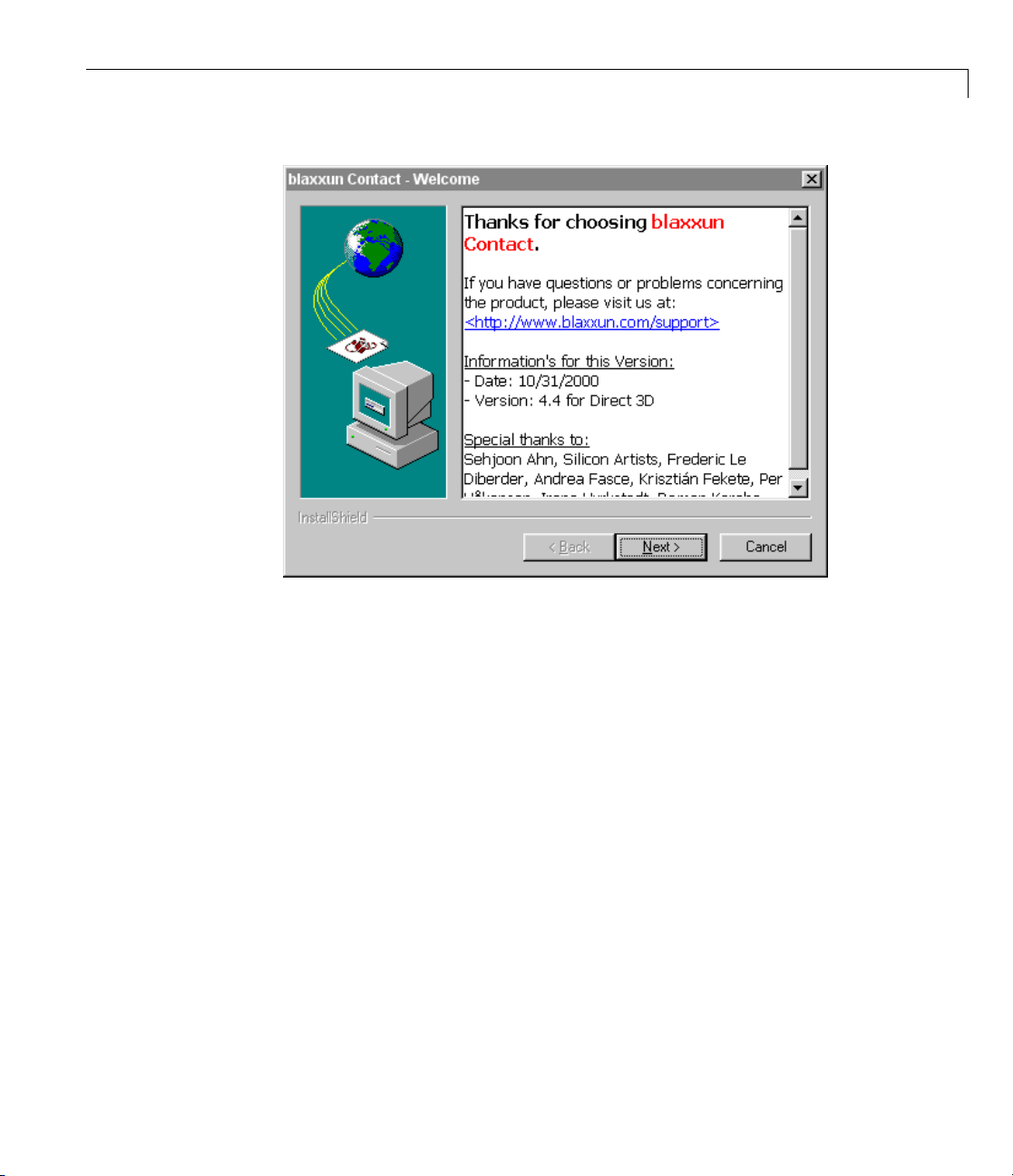
Installing the VRML Plug-In Viewer on the Host Computer
4 Follow the instructions on the remaining screens.
5 In the MA
vrinstall
-check
If the v
displa
External VRML viewer: installed
If th
Wind
VRML
viewer: not installed
TLAB Command Window, type
iewer installation was successful, the MATLAB Command Window
ys the fo llowing message:
e viewer installation was unsuccessful, the MATLAB Command
ow displays the message
2-19
Page 66

2 Installation
Known Issue with the Blaxxun Contact Plug-In
The Blaxxun Contact VRML plug-in can fail to update the virtual scene when
used with the Simulink 3D Animation and Internet Explorer 5.5 and later
products. Netscape Navigator users do not experience this problem.
If you are using Internet Explorer 5.5 or later, you must manually change
a network security setting before you can use Blaxxun Contact 4.4 with
Simulink 3D Animation Version 3.0 or later. Upgrading your version of the
Blaxxun Contact plug-in does not resolve this problem.
Changing the Default Network Security Setting
You must change your default network security setting before using the
Blaxxun Contact plug-in with Internet Explorer 5.5 and later to ensure that
the virtual scene is updated appropriately. You can use this workaround
for the following:
• PC platform is Windows XP Service Pack 1.
• The PC platform is not one of the above, but you have installed the
Microsoft Java Virtual Machine (JVM) on the PC.
2-20
1 Open Internet Explorer.
2 From the Tools menu, choose Internet Options.
The Internet Options dialog box opens.
3 Select the Local Intranet icon.
4 Click the Security tab.
5 Click the Custom Level button.
The Security Settings dialog box opens.
6 Scroll down until you see Microsoft VM. The first subheading is Java
permissions
.
Page 67

Installing the VRML Plug-In Viewer on the Host Computer
7 Select Custom.
The Java Custom Settings button appears in the lower left of the
Security Settings dialog box.
8 Click Java Custom Settings.
The Local intranet dialog box opens.
9 Click the Edit Permissions tab.
10 Scan the main headings and subheadings (marked with a lock icon) until
you see
11 Under Run Unsigned Content,findAccess to all Network Addresses.
12 Under Access to all Network Addresses, select Enable.
13 Click OK.
Run Unsigned Content.
The Local intranet dialog box closes.
14 In the Security Settings dialog box, click OK.
You are asked if you want to change the security settings for this zone.
15 Select Yes.
16 In the Internet Options dialog box, click OK.
Installing a VRML Plug-In (UNIX and Linux)
If you want to use a Web browser instead of the Simulink 3D Animation
viewer to view virtual scenes, you need to install a VRML97 plug-in with
External Authoring Interface (EAI) support. This requirement is met by the
Blaxxun Contact plug-in for Microsoft Microsoft platforms. If you are using
any other operating system, you needtousetheSimulink3DAnimation
viewer to view virtual worlds.
Note The Blaxxun Contact interface is the only supported VRML plug-in.
2-21
Page 68

2 Installation
Setting the Default Viewer of Virtual Scenes
If you install a VRML plug-in in your Web browser, it is possibl e to view
virtual scenes with eith er the Simulink 3D Animation viewer, legacy Simulink
3D Animation viewer, or your Web browser. You determine the viewer
used to display your scene using the
(Alternatively, if you want to use the MATLAB File menu Preferences dialog,
see “Changing Simulink
®
3D Animation Preferences wi th the MATLAB
Preferences Dialog” on page 2-34.)
The following procedure describes how to set the viewer to the Sim ulink 3D
Animation viewer or the Web b rowser. It assumes that you are working on a
PC platform. If you want to use the legacy Simulink 3D Animation viewer,
see “Viewing Virtual Worlds with the Legacy Simulink
Viewer” on page 6-56.
1 At the MATLAB comman d prompt, type
vrinstall -check
vrsetpref and vrgetpref commands.
®
3D Animation
2-22
to determine whether the Blaxxun Contact software is installed.
The MATLAB Command Window displays
VRML
viewer: install ed VRML editor: installed
The viewer and editor are installed. If the viewer is not installed, see
“Installing a VRML Plug-In (Windows)” on page 2-18.
2 Determine your default viewer by typing
vrgetpref
The MATLAB Command Window displays
ans =
DataTypeBool: 'logical'
DataTypeInt32: 'double'
DataTypeFloat: 'double'
DefaultCanvasNavPanel: 'none'
Page 69

Installing the VRML Plug-In Viewer on the Host Computer
DefaultCanvasUnits: 'normalized'
DefaultFigureAntialiasing: 'off'
DefaultFigureCaptureFileFormat: 'tif'
DefaultFigureCaptureFileName: '%f_anim_%n.tif'
DefaultFigureDeleteFcn: ''
DefaultFigureLighting: 'on'
DefaultFigureMaxTextureSize: 'auto'
DefaultFigureNavPanel: 'halfbar'
DefaultFigureNavZones: 'off'
DefaultFigurePosition: [5 92 576 380]
DefaultFigureRecord2DCompressMethod: 'auto'
DefaultFigureRecord2DCompressQuality: 75
DefaultFigureRecord2DFileName: '%f_anim_%n.avi'
DefaultFigureRecord2DFPS: 15
DefaultFigureStatusBar: 'on'
DefaultFigureTextures: 'on'
DefaultFigureToolBar: 'on'
DefaultFigureTransparency: 'on'
DefaultFigureWireframe: 'off'
DefaultViewer: 'internal'
DefaultWorldRecord3DFileName: '%f_anim_%n.wrl'
DefaultWorldRecordMode: 'manual'
DefaultWorldRecordInterval: [0 0]
DefaultWorldRemoteView: 'off'
DefaultWorldTimeSource: 'external'
Editor: [1x60 char]
HttpPort: 8123
TransportBuffer: 5
TransportTimeout: 20
VrPort: 8124
The DefaultViewer property is set to 'internal'. The Simulink 3D
Animation viewer is the default viewer for vie wing virtual scenes. Any virtual
scenes that you open are displayed in the viewer.
3 For example, at the MATLAB command prompt, type
vrplanets
2-23
Page 70

2 Installation
The Planets demo is loaded and the virtual scene is displayed in the
Simulink 3D Animation viewer.
2-24
4 Change the default viewer to your Web b rowser by typing
pref('DefaultViewer','web')
vrset
The default Windows system VRML plug-in is used. The Blaxxun
Contact VRML plug- in sets itself as the default VRM L plug-in during its
installation.
he MATLAB command prompt, type
5 At t
vrplanets
Page 71

Installing the VRML Plug-In Viewer on the Host Computer
The Planets demo is loaded and the virtual scene is displayed in your Web
browser.
6 Reset the Simulink 3D Animation viewer as your default viewer by typing
vrsetpref('DefaultViewer','factory')
7 In the Simulink 3D Animation viewer for vrplanets,fromtheSimulation
menu, select Block Parameters.
A Parameters: VR Sink dialog box opens.
2-25
Page 72

2 Installation
2-26
The ta
prope
View b
If the
open
rget of the View button is determined by the
rty. If the
utton opens the virtual world in the Simulink 3D Animation viewer.
DefaultViewer property is set to 'web', clicking the View button
s the virtual world in your Web browser.
DefaultViewer property is set to 'internal',clickingthe
DefaultViewer
Page 73

Installing the VRML Editor on the Host Computer
Installing the VRML Editor on the Host Computer
In this section...
“Installing the VRML Editor (Windows)” on page 2-27
“VRML Editor (UNIX/Linux)” on page 2-28
“Setting the Default Editor of Virtual Scenes” on page 2-28
Installing the VRML Editor (Windows)
When you install the Simulink 3D An imation product, files are copied to
your hard drive for the Ligos V-Realm Builder software, but the installation
is not complete.
Installing the VRML editor writes a key to the Microsoft Windows registry,
making extra V-Realm Builder library files available for you to use, and it
associates the Edit button in Simulink 3D Animation blocks with this editor:
1 Start the MATLAB software.
2 In the MATLAB Command Window, type
vrinst
-insta
all
ll editor
or type
tall('-install','editor')
vrins
The MATLAB Command Window displays the following messages:
ting editor installation...
Star
e.
Don
2-27
Page 74

2 Installation
3 Type
vrinstall
-check
If the editor installation was successful, The MATLAB Command Window
displays the following message:
VRML editor: installed
VRML Editor (UNIX/Linux)
The MATLAB editor is the default VRML editor for UNIX platforms and no
installation is required. To create your virtual worlds usin g the MATLAB
editor, you need to understand the virtual reality modeling language and the
VRML data types that are relevant to MATLAB. For information about the
modeling language, refer to an appropriate third-party VRML book. Also, see
“VRML Data Types” on page 5-21 for the data types to use with the MATLAB
software.
2-28
Alternatively, you can use a general 3-D modeling tool with VRML97 export
capabilities. Currently, no VRML editor with the functionality of those
available for Windows platforms is commercially available for UNIX platforms.
However, an open source VRML editor,
for UNIX systems. See
for more information.
http://vrml.cip.ica.uni-stuttgart.de/dune/
white_dune, is under development
Setting the Default Editor of Virtual Scenes
You can edit virtual scenes with a VRML authoring tool, such as V-Realm
Builder, or with any text editor, as the VRML language is written in text
files. You determine the editor that is used to edit your scene by using the
vrsetpref and vrgetpref comm ands. (Alternatively, if you want to use
the MATLAB File menu Preferences dialog, see “Changing Simulink
Animation Preferences with the M ATLAB Preferences Dialog” on page 2-34.)
The following procedure demonstrates how to change your editor from
V-Realm Builder to a text editor. It assumes that you are working on a PC
platform.
®
3D
Page 75

Installing the VRML Editor on the Host Computer
1 At the MATLAB comman d prompt, type
vrinstall
-check
to determine whether V-Realm Builder is installed.
The MATLAB Command Window displays
VRML viewer: installed VRML editor: installed
The viewer and editor are ins ta ll ed. If the editor is no t installed, see
“Installing the VRML Editor (Windows)” on page 2-27.
2 Determine your default editor by typing
a = vrgetpref
The MATLAB Command Window displays
a=
DataTypeBool: 'logical'
DataTypeInt32: 'double'
DataTypeFloat: 'double'
DefaultCanvasNavPanel: 'none'
DefaultCanvasUnits: 'normalized'
DefaultFigureAntialiasing: 'off'
DefaultFigureDeleteFcn: ''
DefaultFigureLighting: 'on'
DefaultFigureMaxTextureSize: 'auto'
DefaultFigureNavPanel: 'halfbar'
DefaultFigureNavZones: 'off'
DefaultFigurePosition: [5 92 512 380]
DefaultFigureRecord2DCompressMethod: 'auto'
DefaultFigureRecord2DCompressQuality: 75
DefaultFigureRecord2DFileName: '%f_anim_%n.avi'
DefaultFigureRecord2DFPS: 15
DefaultFigureStatusBar: 'on'
DefaultFigureToolBar: 'on'
DefaultFigureTransparency: 'on'
DefaultFigureWireframe: 'off'
DefaultViewer: 'internal'
2-29
Page 76

2 Installation
DefaultWorldRecord3DFileName: '%f_anim_%n.wrl'
DefaultWorldRecordMode: 'manual'
DefaultWorldRecordInterval: [0 0]
DefaultWorldRemoteView: 'off'
DefaultWorldTimeSource: 'external'
Editor: [1x60 char]
HttpPort: 8123
TransportBuffer: 5
VrPort: 8123
The variable a is a structure array. You need to index into it to determine
the
Editor property.
3 To determine your default editor, type
a.Editor
The MATLAB Command Window displays
ans = "%matlabroot\toolbox\sl3d\vrealm\program\vrbuild2.exe"
"%file"
2-30
This is the path to the V-Realm Builder executable file. V-Realm Builder is
the current VRML editor.
4 Verify that V-Realm Builder is your default editor. At the MATLAB
command prompt, type
vrpend
The Inverted Pendulum demo loads and the pendulum is visible in the
viewer.
5 In the Simulink 3D Animation viewer for vrpend,fromtheSimulation
menu, select Block Parameters
The Parameters: VR Sink dialog box opens.
Page 77

Installing the VRML Editor on the Host Computer
6 Click Edit.
The
vrpend model opens in the V -Realm Builder authoring tool.
2-31
Page 78

2 Installation
2-32
7 At the MA
by typi
vrsetpref('Editor','')
You ca
path t
8 In the Simulink 3D Animation viewer for vrpend,fromtheSimulation
TLAB window, change the default editor to the MATLAB editor
ng
n set your editor to any text editor you want to use by specifying the
o the executable of the text editor.
menu, select Block Parameters.
The Parameters: VR Sink dialog box opens.
ck Edit.
9 Cli
The MATLAB editor opens and is now set as your default VRML editor.
Page 79

Installing the VRML Editor on the Host Computer
10 To reset the V-Realm Builder authoring tool as your default VRML editor,
type
vrsetpref('Editor','factory')
Clicking the Edit button now launches V-Realm Builder.
2-33
Page 80

2 Installation
Changing Simulink 3D Animation Preferences with the
MATLAB Preferences Dialog
In this section...
“Section Overview” on page 2-34
“Simulink®3D Animation Preferences” on page 2-35
“Simulink®3D Animation Canvas Preferences” on page 2-37
“Simulink®3D Animation Figure Preferences” on page 2-37
“Simulink®3D Animation World Preferences” on page 2-45
Section Over view
The topics in this section describe howtosettheSimulink3DAnimation
preferences using the MATLA B File > Preferences dialog. The list of
settable preferences is a subset of those available through the MATLAB
interface functions.
2-34
The Simulink 3D Animation software installs with default preference
settings. You can change these settings with
• MATLAB File > Preferences dialog — This GUI has preference dialogs
for the MATLAB product and its related products, including the Simulink
3D Animation product.
• Simulink 3D Animation MATLAB interface functions
Page 81

Changing Simulink®3D Animation™ Preferen ces with the MATLAB®Preferences Dialog
Simulink 3D Animation Preferences
To access the Simulink 3D Animation preferences GUI:
1 From the MATLAB desktop, select File > Preferences.
2 In the left pane of the Preferences dialog box, select Simulink 3D
Animation.
The Simulink 3D Animation Preferences d ialog ap pears in the right pane.
3 Set the preferences as desired. See the following table for the p references
you can change. Click OK to save the settings.
2-35
Page 82

2 Installation
Preference Value Description
Bool
Default VRML
Viewer
'logical' | 'char'
Default: 'logical'
'internal'
'internalv4' |
'internalv5' |'web'
|
Default: 'internal'
Specifies the handling of the VRML Bool data
type for
If set to
returned as a logical value. If set to
Bool data type is returned 'on' or 'off'.
Specifies which viewer is used to view a virtual
scene. The default Simulink 3D Animation
viewer is used when the preference is set to
'internal' or 'internalv5'.Thelegacy
viewer is used when this preference is set to
'internalv4'. The Web browser is used when
this preference is set to
Note For Linux platforms, 'internal' sets the
viewer to the legacy viewer, and
setstheviewertotheupdatedviewer,whichuses
MATLAB figures.
vrnode/setfield and vrnode/getfield.
'logical',theVRMLBool data type is
'char',the
'web'.
'internalv5'
2-36
Float
Int32
HTTP Port
'single'
| 'doub le'
Default: 'double'
'int32'
| ' doub le'
Default: 'double'
Numeric
Default: 8123
Specifies the handling of the VRML float data
type for
If set to
vrnode/setfield and vrnode/getfield.
'single',theVRMLFloat and Color
data types are returned as 'sing le'.Ifsetto
'double',theFloat and Color data types are
returned as
'double'.
Specifies handling of the VRML Int32 data type
for
vrnode/setfield and vrnode/getfield.If
set to
'int32',theVRMLInt32 data type is
returned as
int32.Ifsetto'double',theInt32
data type is returned as 'double'.
IP port number used to access the Simulink 3D
Animation server over the Web v ia HTTP. If you
change this preference, you must restart the
MATLAB software before the change takes effect.
Page 83

Changing Simulink®3D Animation™ Preferen ces with the MATLAB®Preferences Dialog
Preference Value Description
Transport Buffer
Transport Timeout
Numeric
Default: 5
Numeric
Default: 20
Length of the transport buffer (network packet
overlay) for communication between the Simulink
3D Animation server and its clients.
Amount of time, in seconds, the Simulink 3D
Animationserverwaitsforareplyfromthe
client. If there is no response from the client, the
Simulink 3D Animation server disconnects from
the client.
VRML Editor
command line
VR Port
String Path to the VRML editor. If this path is empty,
the MATLAB editor is used.
Numeric
Default: 8124
IP port used for communication between the
Simulink 3D Animation server and its clients. If
you change this preference, you must restart the
MATLAB software before the change takes effect.
Simulink 3D Animation Canvas Preferences
The Simulink 3D Animation figure has the Navigation panel preference:
Property Value Description
Navigation panel
'none'
'opaque'
| 'translucent' |
Controls the appearance of the
navigation panel in the canvas.
Default: 'none'
Simulink 3D Animation Figure Preferences
The Simulink 3D Animation figure has a number of preferences, presented
in the following categories:
2-37
Page 84

2 Installation
• “Simulink®3D Animation Figure Appearance Preferences” on page 2-38
®
• “Simulink
• “Simulink
• “Simulink
3D Animation Fig ure Rendering Preferences” on page 2-39
®
3D Animation Figure 2-D Recording Preferences” on page 2-41
®
3D Animation Figure Frame Capture Preferences” on page 2-43
Simulink 3D Animation F igure Appearance Preferences
To access the virtual figure appearance preferences:
1 From the MATLAB software desktop, select File > Preferences.
2 In the left pane of the Preferences dialog box, select Simulink 3D
Animation.
3 In the left pane under Simulink 3D Animation,selectFigure.
The Simulink 3D Animation Preferences dialog appears in the right pane,
with the Appearance tab selected.
2-38
4 Set t
he preferences as desired. See the following table for the appearance
erences you can change. Click OK to save the settings.
pref
Page 85
Changing Simulink®3D Animation™ Preferen ces with the MATLAB®Preferences Dialog
Property Value Description
Navigation panel
Navigation zones
'opaque'
'none' | 'halfbar' | 'bar'
Default: 'halfbar'
'off' | 'on'
| 'translucent' |
Controls the appearance of the
navigation panel in the Simulink
3D Animation viewer.
Toggles navigation zones on/off.
Default: 'off'
Position
Status bar
Toolbar
Vector of four doubles Specifies the screen coordinates
'off'
| 'on'
Default: 'on'
'off'
| 'on'
Default: 'on'
of this
Toggles the status bar at the
bottom of the Simulink 3D
Animation viewer.
Toggles the toolbar on the
Simulink 3D Animation viewer.
vrfigure object.
Simulink 3D Animation Figure Rendering Preferences
To access the virtual figure rendering preferences:
1 From the MATLAB desktop, select File > Preferences.
2 In the left pane of the Preferences dialog box, select Simulink 3D
Animation.
3 In the left pane under Simulink 3D Animation,selectFigure.
The Simulink 3D Animation Figure Preferences dialog appears in the
right pane.
4 Select the Rendering tab.
The Simulink 3D Animation Figure Preferences dialog appears in the right
pane, with the Rendering tab selected.
2-39
Page 86

2 Installation
5 Set the preferences as desired. See the following table for the rendering
preferences you can change. Click OK to save the settings.
Property Value Description
Antialiasing
Lighting
'off'
Default: 'off'
'off'
Default: 'on'
| 'on'
| 'on'
Determines whether
antialiasing is used when
rendering scene. Antialiasing
smooths textures by
interpolating values between
texture points.
Specifies whether the lighting
is taken into account when
rendering. If it is off, all
the objects are drawn as if
uniformly lit.
2-40
Page 87

Changing Simulink®3D Animation™ Preferen ces with the MATLAB®Preferences Dialog
Property Value Description
Maximum texture size
'auto' | 32
card limit, where
<= x <= video
x is a
power of 2 (video card limit is
typically
1024 or 2048)
Sets the maximum pixel size
of a texture used in rendering
vrfigure objects. The smaller
the size, the faster the texture
can render. Increasing this
value improves image quality
but decreases performance.
Avalueof
maximum possible pixel size.
If the value you enter is
unsuitable, a warning might
trigger. The software then
automatically adjusts the
property to the next smaller
suitable value.
Textures
Transparency
'off'
Default: 'on'
'off'
Default: 'on'
| 'on'
| 'on'
Turns texture rendering on or
off.
Specifies whether or not
transparency information
is taken into account when
rendering.
Wireframe
'off'
Default: 'off'
| 'on'
Specifies whether objects are
drawnassolidsorwireframes.
'auto' sets the
Simulink 3D Animation Figure 2-D Recording Preferences
To access the virtual figure 2-D recording preferences:
1 From the MATLAB desktop, select File > Preferences.
2 In the left pane of the Preferences dialog box, select Simulink 3D
Animation.
3 In the left pane under Simulink 3D Animation,selectFigure.
The Simulink 3D Animation Preferences d ialog ap pears in the right pane.
2-41
Page 88

2 Installation
4 Select the 2-D Recording tab.
The Simulink 3D Animation Figure Preferences dialog appears in the right
pane, with the 2-D Recording tab selected.
5 Set the preferences as desired. See the following table for the rendering
preferences you can change. Click OK to save the settings.
Property Value Description
2-D animated file name
Recording compression
method
String.
Default:
'' | 'auto' | 'lossless'
| 'codec_code'
'%f_anim_%n.avi'
Default: ' auto '
2-42
Specifies the 2-D offline
animation filename. The
string can contain tokens
that are replaced by the
corresponding information
when the animation recording
takes place. For further
details, see “Animation
Recording File Tokens” on
page 4-12.
Specifies the compression
method for creating 2-D
animation files. The codec
code must be registered in
the system. See the MATLAB
function documentation for
avifile. Read/write.
Page 89

Changing Simulink®3D Animation™ Preferen ces with the MATLAB®Preferences Dialog
Property Value Description
Recording compression
quality
Frames per
second
Integer0–100.
Default:
75
Default: 15
Specifies the default quality of
2-D animation file compression
for new
vrfigure objects.
Specifies the default frames
per second playback speed.
Simulink 3D Animation Figure Frame Capture Pref erences
To access the virtual figure frame capture preferences:
1 From the MATLAB desktop, select File > Preferences.
2 In the left pane of the Preferences dialog box, select Simulink 3D
Animation.
3 In the left pane under Simulink 3D Animation,selectFigure.
The Simulink 3D Animation Figure Preferences dialog appears in the
right pane.
2-43
Page 90

2 Installation
4 Select the Frame Capture tab.
The Simulink 3D Animation Figure Preferences dialog appears in the right
pane, with the Frame C apture tab selected.
5 Set the preferences as desired. See the following table for the rendering
preferences you can change. Click OK to save the settings.
Property Value Description
CaptureFileFormat
CaptureFileName
'tif'
Defaul
String.
Default:
png'
| '
t:
'tif'
'%f_anim_%n.ext'
2-44
Specifies file format for
a captured frame file.
Read/write.
Specifies the frame capture
filename. The string can
contain tokens that are
replaced by the corresponding
information when the
animation recording takes
place. For further details,
see “Frame Capture and
Animation Recording File
Tokens” on page 6-19.
Read/write.
Page 91

Changing Simulink®3D Animation™ Preferen ces with the MATLAB®Preferences Dialog
Simulink 3D Animation World Preferences
To access the virtual world preferences :
1 From the MATLAB desktop, select File > Preferences.
2 In the left pane of the Preferences dialog box, select Simulink 3D
Animation.
3 IntheleftpaneunderSimulink 3D Animation, select World.
The Simulink 3D A nimation World Preferences dialog appears in the
right pane.
2-45
Page 92

2 Installation
4 Set the preferences as desired. See the following table for the rendering
preferences you can change. Click OK to save the settings.
Property Value Description
Allowing viewing from the
Internet
3-D animated file name
Recording mode
'off' | 'on'
Default: 'off'
String.
Default:
'manual' | 'scheduled'
'%f_anim_%n.wrl'
Remote access flag. If the
virtual world is enabled for
remote viewing, it is set to
'on'; otherwise, it is set to
'off'.
3-D animation filename. The
string can contain tokens
that are replaced by the
corresponding information
when the animation recording
takes place. For details, see
“Animation Recording File
Tokens” o n page 4-12.
Animation recording mode.
Recording interval
Time source
2-46
Default: 'manual'
Vector of two doubles
Default:
'external' | 'freerun'
[0 0]
Default: 'external'
Start and stop times for
scheduled animation
recording. Corresponds to
the virtual world object
Time
property.
Sourceofthetimeforthe
virtual world. If set to
'external',timeinthe
scene is controlled from the
MATLAB software (by setting
the
Time property) or the
Simulink software (simulation
time). If set to
'freerun',
time in the scene advances
independently based on the
system timer.
Page 93

Removing Components (Windows)
In this section...
“Section Overview” on page 2-47
“Removing Simulink®3D Animation and Ligos V-Realm Builder (Microsoft
Windows) Software” on page 2-47
“Removing the Blaxxun Contact Plug-In (Windows)” on page 2-48
Section Over view
Normally, you should not have to uninstall the Simulink 3D Animation
software, the Blaxxun Contact plug-in, or Ligos V-Realm Builder. If you need
to do so, this section explains these procedures.
Removing Simulink 3D Animation and Ligos V-Realm
Builder (Microsoft Windows) Software
Use the MathWorks uninstaller. Running this utility removes the Simulink
3D Animation and Ligos V-Realm Builder software from your system. It also
restores your previous system configuration.
Removing Components (Windows®)
1 On the Windows task bar, click Start,pointtoMATLAB,andthenclick
the uninstaller.
The MathWorks uninstaller begins running.
2 Selec
3 Follow the remaining uninstall instructions.
ttheSimulink 3D Animation check box.
Note The Blaxxun Contact plug-in is not uninstalled during the Simulink
3D Animation software removal.
2-47
Page 94

2 Installation
Removing the Bla
To uninstall thi
1 From the Window
Control Panel.
2 In the Control Panel cascading menu, click Add/Remove Programs.
3 In the A dd/R emov e Programs dialog box, select blaxxun Contact,then
click the Change/Remove button.
s VRML plug-in from the host computer:
xxun Contact Plug-In (Windows)
s task bar, click Start,pointtoSettings,andclick
2-48
Page 95

Installing on the C lient Computer
In this section...
“Section Overview” on page 2-49
“Installing a VRML Plug-In (Windows)” on page 2-49
Section Over view
In most configurations, you do not need to install a viewer on a client computer
because you can perform all the tasks on a host compute r . However, if you
have v ery large models that consume considerable computational resources,
you might want to use a client computer to run and view the virtual world.
TheclientcomputermusthaveaVRML97 plug-in with External Authoring
Interface (EAI) support. This means that your client computer must be a
PC platform with the Blaxxun Contact plug-in. Only the Blaxxun Contact
software is supported.
Installing on the Client Computer
“Installing a VRML Plug-In (Windows)” on page 2-18 describes how to install
the Blaxxun Contact VRML plug-in on a computer running Windows.
Installing a VRML Plug-In (Windows)
If you want to view a virtual world on a client computer, you need to use a
Web browser with a VRML plug-in.
The Blaxxun Contact plug-in is provided with the Simulink 3D Animation
software, but you cannot install the Blaxxun Contact plug-in Version 4.4
on a client computer with the MathWorks installer if you do not have this
plug-in installed.
• Copy the file
computer. This file is located at
blaxxuncontact44.exe from your host computer to the client
C:\matlabroot\toolbox\sl3d\blaxxun.
2-49
Page 96

2 Installation
Testing the Installation
In this section...
“Section Overview” on page 2-50
“Running a Simulink Interface Example” on page 2-50
“Running a MATLAB Interface Example” on page 2-55
Section Over view
The Simulink 3D Animation product includes several Simulink models with
the associated virtual worlds. These models are examples of w hat you can do
with this software. You ca n use one of these examples to test the installatio n
of the Simulink 3D Animation software, the VRML viewer, and the VRML
editor.
Running a Simulink Interface Example
In the demo folder for the software, there is a Simulink model for a
two-dimensional inverted pendulum. This model, which you can view in three
dimensions with the software, has an interactive set point and trajectory
graph.
2-50
Beforeyoucanrunthisdemo,youhavetoinstalltheMATLAB,Simulink,
and Simulink 3D Animation products as follows:
1 In the MATLAB Command Window, type
vrpend
A Simulink window opens with the model for an inverted pendulum.
Page 97

Testing the Installation
The Simulink 3D Animatio n vi ewer opens with a 3-D model of the
pendulum.
2-51
Page 98

2 Installation
2-52
2 In the Si
Start.A
running
mulink 3D Animation viewer, from the Simulation menu, click
Trajectory Graph window opens, and a simulation starts
.
Page 99

Testing the Installation
3 In the Simu
surface an
link 3D Animation viewer, point to a position on the blue
dleft-click.
The pendulum set point, represented by the green cone, moves to a new
location. Next, the path is drawn on the trajectory graph, and then the
pendulum itself moves to the new location.
In the Simulink 3D A ni m ation viewer, you see the animated movement of
the pendulum. Use the viewer controls to navigate through the virtual
world, change the viewpoints, and m ove the set point. For more information
about using the Simulink 3D Animation viewer controls, see “Simulink
3D Animation Viewer” on page 6-2.
4 In the
Simulink window, double-click the Trajectory Graph block.
The Block Parameters: Trajectory Graph dialog box opens.
5 From the Setpoint mode list, choose Mouse,thenclickOK.
®
2-53
Page 100

2 Installation
You can now
position
6 Move the mouse pointer into the graph area and click.
The set point (red circle) for the pendulum position moves to a new location.
7 In the Si
The trajectory for the pendulum is displayed in the graph as a blue line.
use the trajectory graph as a 2-D input device to set the
of the pendulum.
mulink window, from the Simulation menu, click Stop.
2-54
 Loading...