


Simscape™ 3
Language Guide

How to Contact The MathWorks
www.mathworks.
comp.soft-sys.matlab Newsgroup
www.mathworks.com/contact_TS.html Technical Support
suggest@mathworks.com Product enhancement suggestions
bugs@mathwo
doc@mathworks.com Documentation error reports
service@mathworks.com Order status, license renewals, passcodes
info@mathwo
com
rks.com
rks.com
Web
Bug reports
Sales, prici
ng, and general information
508-647-7000 (Phone)
508-647-7001 (Fax)
The MathWorks, Inc.
3 Apple Hill Drive
Natick, MA 01760-2098
For contact information about worldwide offices, see the MathWorks Web site.
Simscape™ Language Guide
© COPYRIGHT 2008–20 10 by The MathWorks, Inc.
The software described in this document is furnished under a license agreement. The software may be used
or copied only under the terms of the license agreement. No part of this manual may be photocopied or
reproduced in any form without prior written consent from The MathW orks, Inc.
FEDERAL ACQUISITION: This provision applies to all acquisitions of the Program and Documentation
by, for, or through the federal government of the United States. By accepting delivery of the Program
or Documentation, the government hereby agrees that this software or documentation qualifies as
commercial computer software or commercial computer software documentation as such terms are used
or defined in FAR 12.212, DFARS Part 227.72, and DFARS 252.227-7014. Accordingly, the terms and
conditions of this Agreement and only those rights specified in this Agreement, shall pertain to and govern
theuse,modification,reproduction,release,performance,display,anddisclosureoftheProgramand
Documentation by the federal government (or other entity acquiring for or through the federal government)
and shall supersede any conflicting contractual terms or conditions. If this License fails to meet the
government’s needs or is inconsistent in any respect with federal procurement law, the government agrees
to return the Program and Docu mentation, unused, to The MathWorks, Inc.
Trademarks
MATLAB and Simulink are registered trademarks of The MathWorks, Inc. See
www.mathworks.com/trademarks for a list of additional trademarks. Other product or brand
names may be trademarks or registered trademarks of their respective holders.
Patents
The MathWorks products are protected by one or more U.S. patents. Please see
www.mathworks.com/patents for more information.
Revision History
October 2008 Online only New for Version 3.0 (Release 2008b)
March 2009 Online only Revised for Version 3.1 (Release 2009a)
September 2009 Online only Revised for Version 3.2 (Release 2009b)
March 2010 Online only Revised for Version 3.3 (Release 2010a)

About the Simscape Language
1
What Is the Simscape Language? .................... 1-2
Contents
Typical Tasks
About Simscape Files
Simscape File Type
Model Types
Basic File Structure
Basic Simscape Grammar
Creating a New Physical Domain
When to Define a New Physical Domain
HowtoDefineaNewPhysicalDomain
Creating Custom Components
Component Types and Prerequisites
How to Create a New Behavioral Model
Defining Domain-Wide Parameters
Adding a Custom Block Library
..................................... 1-3
.............................. 1-5
................................ 1-5
...................................... 1-5
............................... 1-8
.......................... 1-10
Writing Simscape Files
................... 1-12
............... 1-12
................ 1-13
...................... 1-14
.................. 1-14
............... 1-14
................... 1-15
...................... 1-16
2
Declaring Domains and Components ................ 2-2
Declaration Grammar
Definitions
Member Declarations
Member Summary
Declaring a Member as a Value with Unit
....................................... 2-3
.............................. 2-2
.............................. 2-4
................................. 2-5
............. 2-5
iii

Declaring Through and Across Variables for a Domain ... 2-6
Declaring Component Variables
Declaring Component Parameters
Declaring Domain Parameters
Declaring Component Nodes
Declaring Component Inputs and Outputs
Example — Declaring a Mechanical Rotational Domain
Example — Declaring a Spring Component
...................... 2-7
.................... 2-8
....................... 2-10
........................ 2-10
............. 2-11
.. 2-12
............ 2-13
Defining Component Setup
Setup Section Purpose
Validating Parameters
Computing Derived Parameters
Setting Initial Conditions
Defining Relationship Between Component Variables and
Nodes
Defining Component Equations
Equation Section Purpose
Equation Grammar
Specifying Mathematical Equality
Use of Relational Operators in Equations
Equation Dimensionality
Equation Continuity
Using Conditional Expressions in Equations
Using Intermediate Terms in Equations
Examples of Equations
Putting It Together — Complete Component
Examples
Mechanical Component Example — Spring
Electrical Component Example — Ideal Capacitor
No-Flow Component Example — Voltage Sensor
Grounding Component Example — Electrical Reference
......................................... 2-19
................................ 2-21
............................... 2-26
....................................... 2-41
......................... 2-15
............................. 2-15
............................. 2-17
...................... 2-17
........................... 2-18
..................... 2-20
........................... 2-20
.................... 2-22
.............. 2-23
........................... 2-25
........... 2-27
............... 2-28
............................. 2-39
............ 2-41
........ 2-44
....... 2-42
.. 2-45
iv Contents
Working with Domain P arameters
Propagation of Domain Parameters
Source Components
Propagating Components
Blocking Components
Example of Using Domain Parameters
................................ 2-48
........................... 2-48
.............................. 2-49
.................. 2-47
................... 2-47
................ 2-49

Attribute Lists ..................................... 2-56
Attribute Types
Model Attributes
Member Attributes
................................... 2-56
.................................. 2-56
................................ 2-57
Subclassing and Inheritance
........................ 2-59
Using Simscape Files in Block Diagrams
3
Adding Custom Block Libraries Generated from
Simscape Component Files
Workflow O v erview
Organizing Your Simscape Files
Using Source Protection for Simscape Files
Converting Your Simscape Files
Customizing the Library Name and Appearance
CustomizingtheLibraryIcon
Example — Creating and Customizing Block Libraries
Specifics of Using Customized Domains
Customizing the Block Name and Appearance
Default Block Display
How to Customize the Block Name
How to Describe the Block Purpose
HowtoSpecifyMeaningfulNamesfortheBlock
Parameters
How to Customize the Names and Locations of the Block
Ports
.......................................... 3-16
How to Customize the Block Icon
Example — Customized Block Display
................................ 3-2
.............................. 3-11
.................................... 3-15
....................... 3-2
..................... 3-3
..................... 3-4
........................ 3-7
................... 3-13
................... 3-14
..................... 3-18
............ 3-3
........ 3-5
... 3-8
............... 3-9
....... 3-11
................ 3-20
Checking File and Model Dependencies
Why Check File and Model Dependencies?
Checking D epende n cies of Protected Files
Checking Simscape File Dependencies
Checking Library Dependencies
Checking Mode l Dependencies
...................... 3-24
....................... 3-24
............. 3-22
............. 3-22
............. 3-23
................ 3-23
v

Case Study — Creating a Basic Custom Block
Library
Getting Started
Building the Custom Library
Adding a Block
Adding Detail to a Component
Adding a Component with an Internal Variable
Customizing the Block Icon
......................................... 3-26
................................... 3-26
........................ 3-27
................................... 3-27
....................... 3-28
......................... 3-32
......... 3-30
Case Study — Creating an Electrochemical Library
Getting Started
Building the Custom Library
Defining a New Domain
Structuring the Library
Defining a Reference Component
Defining an Ideal Source Component
Defining Measurement Components
Defining Basic Components
Defining a Cross-Domain Interfacing Component
Customizing the Appearance of the Library
Using the Custom Components to Build a Model
References
................................... 3-33
........................ 3-34
............................ 3-34
............................ 3-37
..................... 3-37
................. 3-38
.................. 3-39
......................... 3-41
....... 3-44
............ 3-46
........ 3-47
....................................... 3-47
.. 3-33
Index
vi Contents

About the Simscape
Language
• “What Is the Simscape Language?” on page 1-2
• “Typical Tasks” on page 1-3
• “About Simscape Files” on page 1-5
• “Basic Simscape Grammar” on page 1-10
• “Creating a New Physical Domain” on page 1-12
1
• “Creating Custom Components” on page 1-14

1 About the Simscape™ Language
What Is the Simscape Language?
The Simscape™ language extends the Simscape modeling environment by
enabling you to create new components that do not exist in the Foundation
library or in any of the add-on products. It is a dedicated textual language for
modeling physical systems and has the following characteristics:
• Based on the MATLAB
• Contains additional constructs specific to physical modeling
The Simscape language makes modeling physical systems easier and more
intuitive. It lets you define custom componentsastextualfiles,complete
with parameterization, physical connections, and equations represented as
acausal implicit differential algebraic equations (DAEs). The components you
create can reuse the physical domain definitions provided with Simscape to
ensure that your components are compatible with the standard Simscape
components. You can also add your own physical domains. You can
automatically build and manage block libraries of your Simscape components,
enabling you to share these m odels across your organization.
®
programming language
1-2

Typical Tasks
Typical Tasks
Simscape block libraries contain a comprehensive selection of blocks that
represent engineering components such as valves, resis to rs, springs, and so
on. These prebuilt blocks, however, may not be s ufficient to address your
particular engineering needs. When you need to extend the existing block
libraries, use the Simscape language to define customized components, or
even new physical domains, as textual files. Then convert your textual
components into libraries of additional Simscape blocks that you can use in
your model diagrams. For more information on the modeling interface, see
Chapter 3, “Us ing Simscape Files in Block Diagrams”.
The following table lists typical tasks along with links to background
information and examples.
Task
Create a cu
model bas
Add a c
Simsc
ustom block library to
ape libraries
stom component
ed on equations
Background
“Creating
Componen
“Declari
Componen
“Defini
on page 2
“Defin
Equati
“Addi
Libra
Simsc
page 3
“Usi
Sims
“Cus
and
ng Component Setup”
ing Component
ons” on page 2-20
ng Custom Block
ries Generated from
ape Component Files” on
-2
ng Source P rotection for
cape Files ” on page 3-3
tomizing the Block Name
Appearance” on page 3-11
Information
Custom
ts” on page 1 -14
ng Domains and
ts” on page 2-2
-15
Examples
“Example —
Spring Co
2-13
“Mechani
Example
2-41
“Electr
Exampl
on page
“Exam
Custo
on pag
“Exa
Disp
ical Component
ple — Creating and
mizing Block Libraries”
e3-8
mple — Customized Block
lay” on page 3-20
Declaring a
mponent” on page
cal Component
— Spring” on page
e — Ideal Capacitor”
2-42
1-3

1 About the Simscape™ Language
Task
Define a new domain, with
associated Through and Across
variables, and then use it in
custom components
Create a component that
supplies domain-wide
parameters (such as fluid
temperature) to the rest of the
model
Background Information
“Creating a New Physical
Domain” on page 1-12
“Declaring D omains and
Components” on page 2-2
“Working with Domain
Parameters” on page 2-47
Examples
“Example — Declaring
a Mechanical Rotational
Domain” on page 2-12
“Propagation of Domain
Parameters” on page 2-47
“Source Components” on p age
2-48
1-4

About Simscape Files
In this section...
“Simscape File Type” on page 1-5
“Model Types” on page 1-5
“Basic File Structure” on page 1-8
Simscape File Type
TheSimscapefileisadedicatedfiletypeintheMATLABenvironment. It
has the extension
TheSimscapefilecontainslanguageconstructsthatdonotexistinMATLAB.
Theyarespecifictomodelingphysical objects, as described in Chapter 2,
“Writing Simscape Files”. However, the Simscape file incorporates the basic
MATLAB programming syntax at the lowest level.
About Simscape™ Files
.ssc.
Simscape files must reside in a +package directory on the MATLAB path:
•
directory_on_the_path/+MyPackage/MyComp onen t.ssc
• directory_on_the_path/+MyPackage/+Subpackage/.../MyComponent.ssc
For more information on packaging your Simscape files, se e “Organizing
Your Simscape Files” on page 3-3.
Model Types
TherearetwotypesofSimscapefiles,corresponding to the two model types:
• Domain models describe the physical domains through which components
models exchange energy and data. Thes e physical domains correspond to
port types, for example, translational, rotational, hydraulic, and so on.
• Component models describe the physical components that you want to
model, that is, they correspond to Simscape blocks.
1-5

1 About the Simscape™ Language
1-6
A S i mscape file splits the model description into the following pieces:
• Interface or Declaration — Declarative section similar to the MA T L A B
class system declarations:
- For domain models, declares variables (Across and Through) and
parameters
- For component models, declares nodes, inputs and outputs, parameters,
and variables
• Implementation (only for component models) — Describes run-time
functionality of the mode l. Implementation consists of two sections:

About Simscape™ Files
- Setup — Performs initialization and setup. Executed once for each
instance of the component in the top-level model during model
compilation.
- Equation — Describes underly ing equations. Executed throughout
simulation.
Like the MATLAB class system, these constructs and functions act on a
specific instance of the c lass.
Unlike the M ATLA B class system:
• The object is not passed as the first argument to function. This reduces
syntax with no loss of functionality.
• These functions have specific roles in the component lifecycle, as shown in
the following diagram.
Component Instance Lifecycle
1-7

1 About the Simscape™ Language
Phase
Top-Level Model
Construction
Top-Level Model
Compilation
Top-Level Model
Simulation
Steps
1 Invokes file name from MATLAB to construct component instance
2 Adds component instance to top-level model
3 Sets parameters on component instance
4 Connects component instance to other members of the top-level
model
5 Calls the setup function once for each component instance in
the top-level model
6 (Conceptually) calls the equations function for each component
instance in the top-level model repeatedly throughout the
simulation
Basic File Structure
Each model is defined in its o wn file of the same name with a .ssc extension.
For example,
domain model or a component model. Each Simscape file starts with a line
specifying the model class and identifier:
MyComponent is defined in MyComponent .ss c. A model may be a
1-8
ModelClass Identifier
where
•
ModelClass is e ither domain or component
• Identifier isthenameofthemodel
For example:
domain rotational
or
component spring

About Simscape™ Files
The basic file structure for domain models and component models is similar.
1-9

1 About the Simscape™ Language
Basic Simscape Grammar
ThefollowingtabledescribestheSimscape file grammar. Curly braces
{} indicate optional elements. The pipe | indicates a logical OR. Required
characters and keywords are blue.
Model
ModelClass {
( AttributeList ) | Space } Identifier { < Identifier }
Separator
DeclarationSection Separator
{ SetupSection Separator }
{ EquationSection Separator }
end
ModelClass
domain | com
ponent
DeclarationSection DeclarationBlock { Separator DeclarationBlock }
DeclarationBlock
MemberClass
SetupSection
MemberClass {
Identifier
{ Identifier
end
variabl
function setup
= Expression Separator
= Expression Separator }
es
| parameters | inputs | outputs | nodes
( AttributeList ) } Separator
SetupStatement Separator
{ SetupStatement Separator }
end
EquationSection
equations
ExpressionList
end
ExpressionList
EquationExpression { Separator EquationExpression }
EquationExpression
CondExpression
1-10
Expression | CondExpression | LetExpression
if Expression
ExpressionList
{
elseif Expression
ExpressionList }
else
ExpressionList
end

Basic Simscape™ Grammar
LetExpression
let
DeclarationList
in
ExpressionList
end
DeclarationList
Declaration { Separator Declaration }
Declaration LetValue = EquationExpression
LetValue
Identifier | IdentifierList
where
AttributeList Attribute list as defined in the MATLAB class system grammar
Expression
MATLAB expression
Identifier MATLAB identifier
IdentifierList MATLAB identifier list in square brackets []
Separator Comma, semicolon, or newline
SetupStatement A combination of assignment statements, simple if statements,
and
error functions
Space
Required white space, but not newline
1-11

1 About the Simscape™ Language
Creating a New Physical Domain
In this section...
“When to Define a New Physical Domain” on page 1-12
“How to Define a New Physical Dom ain” on page 1-13
When to Define a New Physical Domain
A physical domain provides an environment, defined primarily by its Across
and Through variables, for connecting the components in a Physical Network.
Component nodes are typed by domain, that is, each component node is
associated with a unique type of domain and can be connected only to nodes
associated with the same domain.
You do not need to define a new physical domain to create custom components.
Simscape software comes with several predefined domains, such as
mechanical translational, mechanical rotational, electrical, hydraulic, and so
on. These domains are included in the Foundation library, and are the basis of
Simscape Foundation blocks, as w ell as those in Simscape add-on products (for
example, SimHydraulics
customcomponenttobeconnectedtothestandardSimscapeblocks,usethe
Foundation domain definitions. For a complete listing of the Foundation
domains, see “Simscape Foundation Domains” in the Simscape Reference.
®
or SimElectronics®blocks). If you want to create a
1-12
You need to define a new domain only if the Foundation domain definitions
do not satisfy your modeling requirements. For example, to enable
modeling electrochemical systems, you need to create a new domain with
the appropriate Across and Through variables. If you need to model a
thermohydraulic system, you can create a custom hydraulic domain that
accounts for fluid temperature by supplying a domain-wide parameter (for an
example, see “Propagation of Domain Parameters” on page 2-47).
Once you define a custom physical domain, you can use it for defining nodes
in y our custom components. These nodes, however, can be connected only to
other nodes of the same domain type. For example, if you define a custom
hydraulic domain as described above and then use it when creating custom
components, you will not be able to connect these nodes with the regular

Creating a New Physical Domain
hydraulic ports of the standard Simscape blocks, which use the Foundation
hydraulic domain definition.
How to Define a New Physical Domain
To define a n ew physical domain, you must declare the Through and Across
variables associated with it. F or more information, see “Basic Principles of
Modeling Physical Networks” in the Simscape User’s Guide.
A domain file must begin with the
name, and be terminated by the
domain keyword, followed by the domain
end keyword.
Domain files contain only the declaration section. Two declaration blocks
are required:
• The Across variables declaration block, which begins with the
variables
keyword and is terminated by the end keyword. It contains declarations
for all the Across variables associated with the domain. A domain model
class definition can contain multiple Across variables, combined in a single
variables block.
• The Through variables declaration block, which begins with the
variables(Balancing = true) keyword and is terminated by the end
keyword. It contains declarations for all the Through variables associated
with the domain. A domain model class definition can contain multipl e
Through variables, combined in a single
variables(Balancing = true)
block.
For more information on declaring the Through and Across variables, see
“Declaring Through and Across Variables for a Domain” on page 2-6.
The parameters declaration block is optional. If present, it must begin with
the
parameters keyword and be terminated by the end keyword. This
block contains declarations for domain parameters. These parameters are
associated with the domain and can be propagated through the network to all
components connected to the domain. For more information, see “Working
with Domain Parameters” on page 2-47.
For an example of a domain file, see “Example — Declaring a Mechanical
Rotational Domain” on page 2-12.
1-13

1 About the Simscape™ Language
Creating Custom Components
In this section...
“Component Types and Prerequisites” on page 1-14
“How to Create a New Behavioral Model” on page 1-14
“Defining D omain-Wide Parameters” on page 1-15
“Adding a Custom Block Library” on page 1-16
Component Types and Prerequisites
In physical modeling, there are two types of models:
• Behavioral — A model that is implemented based on its physical behavior,
described by a system of mathematical equations. An example of a
behavioral block implementation is the Variable Orifice block.
• Structural — A model that is constructed out of other blocks, connected
in a certain way. An example o f a structional block implementation is
the 4-Way Directional Valve block (available with SimHydraulics block
libraries), which is constructed based on four Variable Orifice blocks.
1-14
Simscape language lets you create new behavioral models when your design
requirements are not satisfied by the libraries of sta nda rd blocks provided
with Simscape and its add-on products.
You can then use these custom behavioral models either as standalone blocks
or as building blocks for structural models. To create a new structural model,
use mas ke d subsystems. For more information, see “Creating Subsystems” in
the Simulink
A prerequisite to creating components is having the appropriate domains for
the component nodes. You can use Simscape Foundation domains or create
your own, as described in “Creating a New Physical Domain” on page 1-12.
®
User’s Guide.
HowtoCreateaNewBehavioralModel
To create a new behavioral model, define a component model class by writing
a component file.

Creating Custom Components
Acomponentfilemustbeginwiththecomponent keyword, followed by the
component name, and be terminated by the
end keyword.
Component files typically contain three sec tions:
• Declaration — Contains all the member class declarations for the
component, such as parameters, variables, nodes, inputs, and outputs.
Each member class declaration is a separate declaration block, which
begins with the appropriate keyword (corresponding to the member class)
andisterminatedbythe
end keyword. For more information, see the
component-related sections in “Declaring Domains and Components” on
page 2-2.
• Setup — Prepares the component for simulation. The body of the
setup
function can contain assignment statements, if and error statements, and
across and through functions. The setup function is executed once for
each component instance during model compilation. It takes no a rguments
and returns no arguments. For more information, see “Defining Component
Setup” on page 2-15.
• Equation — Declares the component equations. These equations may
be conditional, and are applied throughout the simulation. For more
information, see “Defining Component Equations” on page 2-20.
Defining Domain-Wide Parameters
Another type of a custom block is an environment block that acts as a source
of domain-wide parameters. For example, you can create a Hydraulic
Temperature block that supplies the temperature parameter to the rest
of the model.
Note The Foundation hydraulic domain does not contain a temperature
parameter. You would have to create a customized hydraulic domain where
this parameter is declared. Components using your own customized hydraulic
domain cannot be connected with the components using the Simscape
Foundation hydraulic domain. Use your own customized domain definitions
to build complete libraries of components to be connected to each other.
1-15

1 About the Simscape™ Language
You create environment components similar to behavioral components,
by writing a component file that consists of the declaration, setup, and
equation sections. However, to indicate that this component supplies the
parameter value to the restofthemodel,setthe
this component to
Parameters” o n page 2-47 and “Attribute Lists” on page 2-56.
Adding a Custom Block Library
Adding a custom block librar y involves creating new components (behavioral
or environment). It may involve creating a new physical domain if the
Simscape Foundation domain definitions do not satisfy your modeling
requirements.
After you have created the textual component files, convert them into a
library of blocks using the procedure described in “Adding Custom Block
Libraries Generated from Simscape Component Files” on page 3-2. You can
control the block names and appearance by using optional comments in the
component file. For more information, see “Customizing the Block Name and
Appearance” on page 3-11.
Propagation attribute of
source. For more information, see “Working with Domain
1-16

Writing Simscape Files
• “Declaring Domains and Components” on page 2-2
• “Defining Component Setup” on page 2-15
• “Defining Component Equations” on page 2-20
• “Putting It Together — Complete Component Examples” on page 2-41
• “Working with Domain Parameters” on page 2-47
• “Attribute Lists” on page 2-56
• “Subclassing and Inheritance” on page 2-59
2

2 Writing Simscape™ Files
Declaring Domains and Components
In this section...
“Declaration Grammar” on page 2-2
“Definitions” on page 2-3
“Member Declarations” on page 2-4
“Member Summary” on page 2-5
“Declaring a Memb er as a Value with Unit” o n page 2-5
“Declaring Through and A cross Variables for a Domain” on page 2-6
“Declaring Component Variables” on page 2-7
“Declaring Component Parameters” on page 2-8
“Declaring Domain Parameters” on page 2-10
“Declaring Component Nodes” on page 2-10
“Declaring Component Inputs and Outputs” on page 2-11
2-2
“Example — Declaring a Mechanical Rotational Domain” on page 2-12
“Example — Declaring a Spring Component” on page 2-13
Declaration Grammar

Declaring Domains and Components
The following table describes the declaration s ection grammar. Curly braces
{} indicate optional elements. The pipe | indicates a logical OR. Required
characters and keywords are blue.
Declaration
DeclarationBlock
MemberClass
DeclarationBlock { Separator DeclarationBlock }
MemberClass {
Identifier
{ Identifier
end
variables | parameters | inputs | outputs | nodes
( AttributeList ) } Separator
= Expression Separator
= Expression Separator }
where
AttributeList Attribute list as defined in the MATLAB class system grammar
Expression
MATLAB expression
Identifier MATLAB identifier
Separator Comma, semicolon, or newline
Definitions
The declaration section of a Simscape file may contain one or m ore member
declarations.
Term
Member
Definition
• A member is a piece of a model’s declaration. The collection of
all members of a model is its declaration.
Member class
• It has an associated data type and identifier.
• Each member is associated with a unique member class.
Additionally, members may havesomespecificattributes.
• A member cla ss is the broader classification of a member.
• The following is the set of member classes:
component variables),
parameters, inputs, outputs, nodes.
variables (domain or
• Two members may have the same type, but be of different
member classes. For example, a parameter and an input may
2-3

2 Writing Simscape™ Files
Term
Definition
have the same data type, but because they are of different
member classes, they behave differently.
Member Declarations
The following rules apply to declaring members:
• Like the MATLAB class system, declared members appear in a declaration
block:
<ModelClass> <Identifier>
<MemberClass>
% members here
end
...
end
• Unlike the MATLAB class system, <MemberClass> may take on any of the
available member classes and dictates the member class of the members
defined within the block.
• Like the MATLAB class system, each declared member is associated with
a MATLAB identifier,
members must be declared with a right-hand side value.
<Identifier>. Unlike the MATLAB class system,
2-4
<ModelClass> <Identifier>
<MemberClass>
<Identifier> = <Expression>;
% more members
end
...
end
• <Expression> on the right-hand side of the equal sign (=) is a MATLAB
expression. It could be a constant expression, or a call to a MATLAB
function.
• The MATLAB class of the expression is restricted by the class of the
member being declared. Also, the data type of the expression dictates data
type of the declared member.

Member Summary
The following ta
ble provides the summary of member classes.
Declaring Domains and Components
Member
Class
parameters domain
variables domain
inputs component
outputs componen
nodes compone
Applicable
Model Classes
component
component
nt
Note When a member i s writable, it means that it can be assigned to in
the
setup function. Nodes are themselves not writable, b ut their writable
members (parameters and variables) are.
Declaring a Member as a Value with Unit
In Simscape language, declaration members such as parameters, variables,
inputs, and outputs, are represented as a value with associated unit. The
syntax for a value with unit is essentially that of a two-member value-unit
cell array:
MATLAB Class of
Expression
Numerical value with
Expression
Meaning
Default value
Writable
Yes
unit
Double value
with unit
Nominal valu
and default
e
initial
Yes
condition
Scalar dou
ble value
Default va
lue
No
with unit
t
Scalar do
uble value
Default v
alue
No
with unit
Instanc
associa
eofanode
ted with a
Type of d
omain
No
domain
{ value , 'unit' }
where value is a real matrix, includin g a scalar, and unit is a valid unit
string, defined in the unit registry, or
1 (unitless). Depending on the member
type, certain restrictions may apply. See respective reference pages for details.
For e xample, this is how you declare a parameter as a value with unit:
2-5

2 Writing Simscape™ Files
par1 = { value , 'unit' };
As in MATLAB, the comma is not required, and this syntax is equivalent:
par1 = { value 'unit' };
To declare a unitless parameter, you can either use the same syntax:
par1 = { value , '1' };
or omit the unit and use this syntax:
par1 = value;
Internally, however, this parameter will be treated as a two-member
value-unit cell array
{ value , '1' }.
Declaring Through and Across Variables for a
Domain
In a domain file, you have to declare the Through and Across variables
associated with the domain. These variables characterize the energy flow and
usually come in pairs, one Through and one Across. Simscape language does
not require that you have the same number of Through and Across variables
in a domain definition, but it is highly recommended. For more information,
see “Basic Principles of Modeling Physical Networks” in the Simscape User’s
Guide.
2-6
variables begins an Across variables declaration block, which is terminated
by an
end key w ord. This block contains declarations for all the Across
variables associated with the domain. A domain model class definition can
contain multiple Across variables, combined in a single
This block is required.
Through variables are semantically distinct in that their values have to
balance at a node: for each Through variable, the sum of all its values flowing
into a branch point equals the sum of all its values flowing out. Therefore,
a domain file must contain a separate declaration block for its Through
variables, with the
Balancing attribute set to true,
variables block.

Declaring Domains and Components
variables(Balancing = true) begins a T hrough variables definition block,
which is terminated by an
end key word. This block contains declarations
for all the Through variables associated with the domain. A domain model
class definition can contain multiple Through variables, combined in a single
variables(Balancing = true) block. This block is required.
Each variable is defined as a value with un i t:
domain_var1 = { value , 'unit' };
value
is the initial val ue. unit is a valid unit string, defined in the unit
registry. See “Example — Declaring a Mechanical Rotational Domain” on
page 2-12 for more information.
Declaring Component Variables
When you declare Through and Across variables in a component, you are
essentially creating instances of domain Through and Across variables. You
declareacomponentvariableasavaluewithunitbyspecifyinganinitial
value and units commensurate with units of the domain variable.
The following example initializes the Through variable
variables
t = { 0, 'N*m' };
end
Note After you declare component variables, you have to use through and
across functions in the setup section to specify their relationship with
component nodes.
You can also declare an internal component variable as a value with unit. You
can use such internal variables in the setup and equation sections. Unlike
component parameters, internal component varia bles do not appear in a block
dialog box of the Simscape block generated from the component file.
t (torque) as 0 N*m:
2-7

2 Writing Simscape™ Files
Declaring Compo
Component param
block generated
dialog box and c
You declare ea
comment lets y
more informat
Parameters”
The followin
ecifying the spring rate of a rota ti onal spring. In the block dialog
N*m/rad
box, this pa
,sp
rameter will be named S pring rate.
parameters
k = { 10, 'N*m/rad' }; % Spring rate
end
eters let you specify adjustable parameters for the Simscape
from the component file. Parameters will appear in the blo ck
an be modified when building and simulating a model.
ch parameter as a value with unit. Specifying an optional
ou control the parameter name in the block dialog box. For
ion,see“HowtoSpecifyMeaningfulNamesfortheBlock
on page 3-15.
g example declares parameter
nent Parameters
k, with a default value of 10
Specifying Parameter Units
When you declare a component parameter, use the units that make sense in
the context of the block application. For example, if you model a solenoid, it is
more convenient for the block user to input stroke in millimeters rather than
in meters. When a parameter is used in the setup and equation sections,
Simscape unit manager handles the conversions.
2-8
With temperature units, however, there is an additional issue of whether
to apply linear or affine conversion (see “Thermal Unit Conversions” in the
Simscape User’s Guide). Therefore, when you declare a parameter with
temperature units, you can specify only nonaffine units (kelvin or rankine).
When the block user enters the parameter value in affine units (Celsius or
Fahrenheit), this value is automatically converted to the units specified in
the parameter declaration. By default, affine conversion is applied. If a
parameter specifies relative, rather than absolute, tempe rature (in other
words, a change in temperature), set its
(for details, see “Member Attributes” on page 2-57).
Conversion attribute to relative

Declaring Domains and Components
Note Member attributes apply to a whole DeclarationBlock. If some of your
parameters are relative and others are absolute, declare them in separate
blocks. Youcanhavemorethanonedeclarationblockofthesamemember
type within a Simscape file.
Case Sensitivity
Simscape language is case-sensitive. This means that member names
may differ only by case. However, Simulink software is not case-sensitive.
Simulink parameter names (that is, parameter names in a block dialog box)
must be unique irrespective of case. Therefore, if you declare two parameters
whose names differ only by case, such as
component MyComponent
parameters
A=0;
a=0;
end
end
you will not be able to generate a block from this component.
However, if one of the parameters is priva te or hidden, that is, does not
appear in the block dialog box,
component MyComponent
parameters(Access=private)
A=0;
end
parameters
a=0;
end
end
orifoneisdeclaredasaparameterandanotherasavariable,suchas
component MyComponent
variables
A=0;
2-9

2 Writing Simscape™ Files
end
parameters
a=0;
end
end
then there is no conflict in the Simulink namespace and no problem
generating the block from the component source.
The case-sensitivity restriction applies only to component parameters,
because other member types do not have an associated Simulink parameter,
and are therefore completely case-sensitive.
Declaring Domain Parameters
Similar to a component parameter, you declare each domain parameter as a
value with unit. However, unlike component parameters, the main p urpose of
domain parameters is to propagate the same parameter value to all or some of
the components connected to the domain. For more information, see “Working
with Domain Parameters” on page 2-47.
2-10
Declaring Component Nodes
Component nodes define the conserving ports of a Simscape block generated
from the component file. The type of the conserving port (electrical,
mechanical rotational, and so on) is d etermined by the type of its parent
domain. The domain defines which Through and Across variables the port can
transfer. Conserving ports o f Simscape blocks can be connected only to ports
associated with the same domain. For more information, see “Basic Principles
of Modeling Physical Networks” in the Simscape User’s Guide.
When declaring nodes in a component, you have to associate them with an
existing dom ain. You need to refer to the domain name using the full path
starting with the top package directory. For more information on packaging
your Simscape files, see “Adding Custom Block Libraries Generated from
Simscape Component Files” on page 3-2.
The following example uses the syntax for the Simscape Foundation
mechanical rotational domain:

Declaring Domains and Components
nodes
r = foundation.mechanical.rotational.rotational;
end
Thenameofthetop-levelpackagedirectoryis+foundation.Itcontainsa
subpackage
contains the domain file
+mechanical, with a subpackage +rotational, which in turn
rotational.ssc.
Ifyouwanttouseyourowncustomizedrotationaldomaincalled
rotational.ssc and located at the top level of your custom package directory
+MechanicalElements, the syntax would be:
nodes
r = MechanicalElements.rotational;
end
Note Components using your own custom ized rotational domain cannot be
connected with the components using the Simscape Foundation mechanical
rotational domain. Use your own customized domain definitions to build
complete libraries of components to be connected to each other.
Specifying an optional comment lets you control the port label and location
in the block icon. For more information, see “How to Customize the Names
and Locations of the Block Ports” on page 3-16. In the following example, the
electrical conserving port will be labelled + and will be located on the top
side of the blo ck icon.
nodes
p = foundation.electrical.electrical; % +:top
end
Declaring Component Inputs and Outputs
In addition to conserving ports, Simscape blocks can contain Physical Signal
input and output ports, directional ports that carry signals with associated
units. These ports are defined in the
of a component file. Each input or output is defined as a value with unit.
inputs and outputs declaration blocks
2-11

2 Writing Simscape™ Files
Specifying an optional comment lets you control the port label and location in
theblockicon. Formoreinformation,see“HowtoCustomizetheNamesand
Locations of the Block Ports” on page 3-16.
The following example declares an input port
, specifying the control port of a hydraulic pressure source. In the block
Pa
s,withadefaultvalueof1
diagram, this port will be named Pressure and will be located on the top
side of the blo ck icon.
inputs
s = { 1, 'Pa' }; % Pre ssur e:top
end
Example — Declaring a Mechanical Rotational
Domain
The following file, named rotational.ssc, declares a mechanical rotational
domain, with angular velocity as an Across variable and torque as a Through
variable.
domain rotational
% Define the mechanical rotational domain
% in terms of across and through variables
variables
w = { 1 , 'rad/s' }; % angul ar velocity
end
variables(Balancing = true)
t = { 1 , 'N*m' }; % torque
end
2-12
end
Note This domain declaration corresponds to the Simscape Foundation
mechanical rotational domain. For a complete listing of the Foundation
domains, see “Simscape Foundation Domains” in the Simscape Reference.

Declaring Domains and Components
Example — Declar
The following di
mass-spring-da
damper, and ref
agram shows a network representation of a
mper system, consisting of four components (mass, spring,
erence) in a mechanical rotational domain.
ing a Spring Component
The domain is declared in a file named rotational.ssc (see “Example —
Declaring a Mechanical Rotational Domain” on page 2-12). The following
file, named
spring.ssc, declares a component called spring. The component
contains:
• Two rotational nodes,
• Parameter
k, with a default value of 10 N*m/rad, specifying the spring rate
• Through and Across variables, torque
r and c (for rod and case, respectively)
t and angular velocity w, later to be
related to the Through and Across variables of the rotational domain
• Internal variable
theta, with a default value of 0rad,specifyingrelative
angle, that is, deformation of the spring
component spring
nodes
r = foundation.mechanical.rotational.rotational;
c = foundation.mechanical.rotational.rotational;
end
parameters
2-13

2 Writing Simscape™ Files
k = { 10, 'N*m/rad' }; % spring rate
end
variables
theta = { 0, 'rad' }; % introduce new va riable for spring deformation
t = { 0, 'N*m' }; % torque through
w = { 0, 'rad/s' }; % velocity across
end
% setup here
% equations here
end
Note T his exam ple shows only the declaration section of the spring
component. For a complete file listing of a spring component, including the
setup and equations, see “Mechanical Component Example — Spring” on
page 2-41.
2-14

Defining Component Setup
In this section...
“Setup Section Purpose” on page 2-15
“Validating Parameters” on page 2-17
“Computing Derived Parameters” on page 2-17
“Setting Initial Conditions” on page 2-18
“Defining Relationship Between Component Variables and Nodes” on page
2-19
Setup Section Purpose
Defining Component Setup
The setup section of a Simscape file follows the declaration section and
consists of the function named
each component instance during model compilation. It takes no arguments
and returns no arguments.
Note Setup is not a constructor; it prepares the component for simulation.
Use the setup function for the following purposes:
• Validating parameters
setup.Thesetup function is ex ecuted once for
2-15

2 Writing Simscape™ Files
• Computing derived parameters
• Setting initial conditions
• Relating variables and nodes to one another by using
across and through
functions
The following rules apply:
• The
setup function is executed as regular MATLAB code.
• All members declared in the component are available by their name, for
example:
component MyComponent
parameters
p = {1, 'm' };
end
[...]
function setup
disp( p ); % during compilation, prints value of p
% for each instance of MyComponent in the model
[...]
end
• All members (such as variables, parameters) that are externally writable
are writable within setup. See “Member Summary” on page 2-5 for more
information.
• Local MATLAB variables may be introduced in the
arescopedonlytothe
setup function.
setup function. They
2-16
The following restrictions apply:
• Command syntax is not supported in the
setup function. You must use
the function syntax. For more information, see “Command vs. Function
Syntax” in the MATLAB Programming Fundamentals documentation.
• Persistent and global variables are not supported. For more information,
see “Types of Variables” in the MATLAB Programming Fundamentals
documentation.
• MATLAB system comm ands using the
! operator are not supported.

Defining Component Setup
• try-end and try-catch-end constructs are not supported.
• Passing declaration members to external MATLAB functions,
for example,
my_function(param1), is not supported. You can,
however, pass member values to external functions, for example,
my_function(param1.value('unit')).
Validating Parameters
The setup function validates parameters using simple if statements and the
error function. For example:
component MyComponent
parameters
LowerThreshold = {1, 'm' };
UpperThreshold = {1, 'm' };
end
[...]
function setup
if LowerThreshold > Upper Threshold
error( 'LowerThreshold is greater than UpperThreshold' );
end
end
[...]
end
Computing Derived Parameters
The setup function can override parameters by assigning to them. For
example, it can verify that a parameter is not greater than the maximum
allowed value, and if it is, issue a warning and assign the maximum allowed
value to the parameter:
component MyComponent
parameters
MyParam = {1, 'm' };
end
[...]
function setup
MaxValue = {1, 'm' };
if MyParam > MaxValue
warning( 'MyParam is greater than MaxValue, ove rriding with MaxValue' );
2-17

2 Writing Simscape™ Files
MyParam = MaxValue;
end
end
[...]
end
Note Members are strongly typed. In the example above, MaxValue must
havethesamedatatypeandcompatibleunitas
MyParam.Otherwise,you
will get an error.
Setting Initial Conditions
As you declare variables, values that you assign to them are their initial
conditions. How ever, you can use the
conditions by assigning the variable a new value, for example:
component MyComponent
variables
MyVariable = {1, 'm' };
end
[...]
function setup
MaxValue = {1, 'm' };
if MyVariable > MaxValue
warning( 'Initial value of MyVariable is greater than MaxValue, overriding with MaxValue' );
MyVariable = MaxValue; % MyVariable(t = 0) = Ma xValue
end
end
[...]
end
setup function to override these initial
2-18
Note Variables are also strongly typed. In the example above, MaxValue must
have the same data type and compatible unit as
MyVariable.Otherwise,
you will get an error.

Defining Component Setup
Defining Relationship Between Component Variables
and Nodes
Use the across and through functions to establish relationship between the
component variables and nodes. The
because the same relationship for the Across variables could be established in
the equation section, but it acts as shorthand and adds notation that clearly
illustrates the relationship among the variables. The
only way to establish relationship between the Through variables. These
functions are especially helpful when the component has multiple nodes
because they clearly indicate branches.
across function is not strictly necessary
through function is the
In the following example,
r and c are rotational nodes, while t and w are
component variables for torque and angular velocity, respectively. The setup
section defines the relationship between the variables and n odes:
component spring
nodes
r = foundation.mechanical.rotational.rotational;
c = foundation.mechanical.rotational.rotational;
end
[...]
variables
[...]
t = { 0, 'N*m' }; % torque through
w = { 0, 'rad/s' }; % velocity across
end
function setup
through( t, r.t, c .t ); % t a through variable from r to c
across(w, r.w, c.w ); % w an across variable from r to c
[...]
end
% equations here
end
2-19

2 Writing Simscape™ Files
Defining Component Equations
In this section...
“Equation Section Purpo se” on page 2-20
“Equation Grammar” on page 2-21
“Specifying Mathematical Equality” on page 2-22
“Use of Relational Operators in Equations” on page 2-23
“Equation Dimensionality” on page 2-25
“Equation Continuity” on page 2-26
“Using Conditional Expressions in Equations” on page 2-27
“Using Intermediate Terms inEquations”onpage2-28
“Examples of Equations” on page 2-39
Equation Section Purpose
2-20
The equation section of a Simscape file follows the declaration and setup
sections. It is executed throughout the simulation. The purpose of the
equation section is to establish the mathematical relationships among a
component’s variables, parameters, inputs, outputs, time and the time
derivatives of each of these entities.

Defining Component Equations
Equation Grammar
The following table describes the equation section grammar. Brackets {}
indicate optional eleme n ts . The pipe | indicates a logical OR. Required
characters and keywords are blue.
EquationSection
ExpressionList
EquationExpression
CondExpression
LetExpr
Decla
Decl
ession
rationList
aration
LetValue
equations
ExpressionList
end
EquationExpression { Separator EquationExpression }
Expression | CondExpression | LetExpression
if Expression
ExpressionList
{
elseif Expression
ExpressionList }
else
ExpressionList
end
let
DeclarationList
in
ExpressionList
end
Declaration { Separator Declaration }
alue
LetV
ntifier | IdentifierList
Ide
= EquationExpression
Expression
entifier
Id
dentifierList
I
eparator
S
where
TLAB expression
MA
TLAB identifier
MA
ATLAB identifier list in square brackets
M
omma, semicolon, or newline
C
[]
2-21

2 Writing Simscape™ Files
Specifying Mathematical Equality
Simscape language stipulates semantically that all the equation expressions
returned by the equation section of a Simscape file specify continuous
mathematical equality between two expressions. Consider a simple example:
equations
Expression1 == Expression2;
end
Here we have declared an equality between Expression1 and Expression2.
The left- and right-hand side expressions are any valid MATLAB expressions
(see the next section for restrictions on us ing the relational operators:
<=, >=,~=, &&, ||). The equation expressions may be constructed from any of
the identifiers defined in the model declaration.
The equation is defined with the == operator. This means that the equation
does not represent assignment but rather a symmetric mathematical
relationship between the left- and right-hand operands. Because == is
symmetric, the left-hand operand is not restricted to just a variable. F or
example:
==, <, >,
2-22
component MyComponent
[...]
variables
a=1;
b=1;
c=1;
end
equations
a+b==c;
end
end
The following example is mathematically equivalent to the previous example:
component MyComponent
[...]
variables
a=1;
b=1;

Defining Component Equations
c=1;
end
equations
0==c-a-b;
end
end
Note Equation expressions must be terminated w ith a semicolo n or a newline.
Unlike MATLAB, the absence of a semicolon makes no difference. In any case,
Simscape language does not d isplay th e result as it evaluates the equation.
Use of Relational Operators in Equations
In the previous section we discussed how == is used to declare mathematical
equalities. In MATLAB, however,
operator. For example:
(a == b) * c;
== yields an expression like any other
where a, b,andc represent scalar double values, is a legal MATLAB
expression. This would mean, take the
equivalence to
same as
b,coercethisvaluetoadouble and multiply by c.Ifa is the
b, then this expression will return c. Otherwise, it will return 0.
On the other hand, in MATLAB we can use
a == b == c;
logical value generated by testing a’s
== twicetobuildanexpression:
This expression is ambiguous, but MATLAB makes == and other relational
operators left associative, so this expression is treated as:
(a == b) == c;
The subtle difference between (a == b) == c and a==(b==c)can be
significant in MATLAB, but is even more significant in an equation. Because
the use of
== is significant in the Simscape language, and to avoid ambiguity,
the following syntax:
component MyComponent
2-23

2 Writing Simscape™ Files
[...]
equations
a == b == c;
end
end
is illegal in the Simscape language. You must explicitly associate top-level
occurrences of relational operators. Either
component MyComponent
[...]
equations
(a == b) == c;
end
end
or
component MyComponent
[...]
equations
a==(b==c);
end
end
2-24
are legal. In either case, the quantity in the parentheses is equated to the
quantity on the other side of the equation.
With the exception of the top-level use of the
== operator, == and other
relational operators are left associativ e. For example:
component MyComponent
[...]
parameters
a=1;
b=1;
c = false;
end
variables
d=1;

end
equations
(a == b == c) == d;
end
end
is legal and interpreted as:
component MyComponent
[...]
parameters
a=1;
b=1;
c = false;
end
variables
d=1;
end
equations
((a==b)==c)==d;
end
end
Defining Component Equations
Equation Dimensionality
The expressions on either side of the == operator need not be scalar
expressions. They must be either the same size or one must be scalar. For
example:
equations
[...]
<3x3 Expression> == <3x3 Expression>;
[...]
end
is legal and introduces 9 scalar equations. The equation expression:
equations
[...]
<1x1 Expression> == <3x3 Expression>;
[...]
2-25

2 Writing Simscape™ Files
end
is also legal. Here, the left-hand side of the equation is expanded, via scalar
expansion, into the same expression replicated into a 3x3 matrix. This
equation expression also introduces 9 scalar equations.
However, the equation exp ress ion:
equations
[...]
<2x3 Expression> == <3x2 Expression>;
[...]
end
is illegal because the sizes of the expressions on the left- and right-hand side
are different.
Equation Continuity
The equatio n section is evaluated in continuous time. Some of the values that
are accessible in the equation section are themselves piecewise continuous,
that is, they change continuously in time. These values are:
2-26
• variables
• inputs
• outputs
• time
Piecewise continuous indicates that values are continuous over compact time
intervals but may change value at certain instances. The following values
are continuous, but not time-varying:
• parameters
• constants
Time-varying countable values, for example, integer or logical, are never
continuous.

Defining Component Equations
Continuity is propagated like a data type. It is propagated through continuous
functions (see “Supported Functions”).
Using Conditional Expressions in Equations
You can specify conditional equations by using if statements.
equations
[...]
if Expression
[...]
elseif Expression
[...]
else
[...]
end
[...]
end
Each [...] section may contain one or more equation expressions.
Note The total num ber of equation expressions, their dime ns iona lity, and
their order must be the same for every branch of the
if-elseif-else
statement.
You can nest if state m ents, for example:
equations
[...]
if Expression
[...]
if Expression
[...]
else
[...]
end
else
[...]
2-27

2 Writing Simscape™ Files
end
[...]
end
Every if requires an else.
Example
For a component where x and y are declared as 1x1 variables, specify the
following piecewise equation:
xx
⎧
⎪
y
=
⎨
2
x
⎪
⎩
−<= <=
for
11
otherwise
This equation, written in the Simscape language, would look like:
equations
ifx>=-1&&x<=1
y==x;
else
y == x^2;
end
end
Another way to write this equation in the Simscape language is:
equations
y == if x>=-1 && x<=1, x else x^2 end
end
Using Intermediate Terms in Equations
• “Why Use Intermediate Terms?” on page 2-29
• “Syntax Rules” on page 2-30
2-28
• “Nested
• “Conditional
let Expressions” on page 2-33
let Expressions” on page 2-35
• “Identifier List in the Declarative Clause” on page 2-37

Defining Component Equations
Why Use Intermediate Terms?
Textbooks often define certain equation terms in separate equations, and
then substitute these intermediate equations into the main one. For example,
for fully developed flow in ducts, the Darcy friction factor can be used to
compute pressure loss:
2
D
2
P
=
fL V
iiiρ
where P is pressure, f is the Darcy friction factor, L is length, ρ is density, V is
flow velocity, and
D is hydraulic area.
Thesetermsarefurtherdefinedby:
.
0 316
f =
14
Re
DVi
Re =
DA=
V
ν
4
π
q
=
A
where Re is the Reynolds number, A is the area, q is volumetric flow rate, and
ν is the kinematic viscosity.
In Simscape language, you can define intermediate terms and use them in
one or more equations by using the
let expressions. The following example
shows the same equations written out in Simscape language:
component MyComponent
[...]
parameters
L = { 1, 'm' }; % length
rho = { 1e3, 'kg/m^3' }; % density
2-29

2 Writing Simscape™ Files
nu = { 1e-6, 'm^2/s' }; % kinematic viscosity
end
variables
p = { 0, 'Pa' }; % pressure
q = { 0, 'm^3/s' }; % volumetric flow rate
A = { 0, 'm^2' }; % area
end
equations
let
f = 0.316 / Re_d^0.25; % Darcy friction factor
Re_d = D_h * V / nu; % Reynolds number
D_h = sqrt( 4.0 * A / pi ); % hydraulic area
V = q / A; % flow velocity
in
p == f * L * rho * V^2 / (2 * D_h); % final equation
end
end
end
2-30
After substitution of all intermediate terms, the final equation becomes:
p==0.316/(sqrt(4.0 * A / pi) * q/A/nu)^0.25 * L * rho * (q / A)^2 / (2 * sqrt(4.0 * A / pi));
Syntax Rules
A let expression consists of two clauses, the declaration clause and the
expression clause.
equations
[...]
let
declaration clause
in
expression clause
end
[...]
end

Defining Component Equations
The declaration clause assigns an identifier, or set of identifiers, on the
left-hand side of the equal sign (
=)toanequationexpressionontheright-hand
side of the equal sign:
LetValue = EquationExpression
The expression clause defines the scope of the substitution. It starts with
the keyword
in, and may contain one or more equatio n expressions. All
the expressions assigned to the identifiers in the declaration clause are
substituted into the equations in the expression clause during parsing.
Note The end keyword is required at the end of a let-in-end statement.
Here is a simple example:
component MyComponent
[...]
variables
x=0;
y=0;
end
equations
let
z=y+1;
in
x==z;
end
end
end
In this example, the declaration clause of the le t expression sets the value of
the identifier
expression clause in the
component MyComponent
[...]
variables
z to be the expression y + 1. Thus, substituting y +1forz in the
let statem ent, the code above is equivalent to:
x=0;
y=0;
2-31

2 Writing Simscape™ Files
end
equations
x==y+1;
end
end
end
There may be multiple declaratio ns in the declaration clause. These
declarations are order independent. The identifiers declared in one
declaration may be referred to by the expressions for identifiers in other
declarations in the same declaration clause. Thus, in the code example shown
in the previous section, the identifier
the expression d eclaring the identifier
Re_d (Reynolds number) is used in
f (Darcy friction fa ctor). The only
requirement is that the expression references are acyclic.
The expression clause of a
let expression defines the scope of the substitution
for the declaration clause. Other equations, that do n ot require these
substitutions, may appear in the equation section outside of the expression
clause. In the following example, the equation section contains the equation
expression
component MyComponent
end
c==b+2outside the scope of the let expression before it.
[...]
variables
a=0;
b=0;
c=0;
end
equations
let
x=a+1;
in
b==x;
end
c==b+2;
end
These expressions are treated as peers. They are order independent, so this
example is equivalent to
2-32

component MyComponent
[...]
variables
a=0;
b=0;
c=0;
end
equations
c==b+2;
let
x=a+1;
in
b==x;
end
end
end
and, after the substitution, to
component MyComponent
[...]
variables
a=0;
b=0;
c=0;
end
equations
b==a+1;
c==b+2;
end
end
Defining Component Equations
Nested let Expressions
You can nest let expressions, for example:
component MyComponent
[...]
variables
a=0;
2-33

2 Writing Simscape™ Files
b=0;
c=0;
end
equations
let
w=a+1;
in
let
z=w+1;
in
b==z;
c==w;
end
end
end
end
In case of nesting, substitutions are performed based on both of the
declaration clauses. After the substitutions, the code above becomes:
2-34
component MyComponent
[...]
variables
a=0;
b=0;
c=0;
end
equations
b==a+1+1;
c==a+1;
end
end
The innermost declarations take precedence. The following example
illustrates a nested
let expression where the inner declaration clause
overrides the value declared in the outer one:
component MyComponent
[...]
variables

a=0;
b=0;
end
equations
let
w=a+1;
in
let
w=a+2;
in
b==w;
end
end
end
end
Performing substitution on this example yields:
component MyComponent
[...]
variables
a=0;
b=0;
end
equations
b==a+2;
end
end
Defining Component Equations
Conditional let Expressions
You can use if statements within both declarative and expression clause of
let expressions, for example:
component MyComponent
[...]
variables
a=0;
b=0;
c=0;
2-35

2 Writing Simscape™ Files
end
equations
let
x=ifa<0,aelsebend;
in
c==x;
end
end
end
Here x is declared as the conditional expression based on a <0.Performing
substitution on this example yields:
component MyComponent
[...]
variables
a=0;
b=0;
c=0;
end
equations
c == if a < 0, a else b end;
end
end
2-36
The next example illustrates how you can use let expressions within
conditional expressions. The two
let expressions on either side of the
conditional expression are independent:
component MyComponent
[...]
variables
a=0;
b=0;
c=0;
end
equations
if a < 0
let
z=b+1;

in
c==z;
end
else
let
z=b+2;
in
c==z;
end
end
end
end
This code is equivalent to:
component MyComponent
[...]
variables
a=0;
b=0;
c=0;
end
equations
if a < 0
c==b+1;
else
c==b+2;
end
end
end
Defining Component Equations
Identifier List in the Declarative Clause
This example shows using an identifier list, ra ther that a single identifier, in
the declarative clause of a
component MyComponent
[...]
variables
let expression:
2-37

2 Writing Simscape™ Files
a=0;
b=0;
c=0;
d=0;
end
equations
let
[x, y] = if a < 0, a; -a else -b; b end;
in
c==x;
d==y;
end
end
end
Here x and y are declared as the conditional expression based on a <0.
Notice that each side of the
first semantic translation of this example separates the
if a < 0, a; -a else -b; b end =>
{ifa<0,aelse -b end; ifa<0,-aelse b end }
if s tatement defines a list of two expressions. A
if statement into
2-38
then the second semantic translation becomes
[x,y]={ifa<0,aelse -b end; ifa<0,-aelse b end } =>
x=ifa<0,aelse-bend;y=ifa<0,-aelse b end;
and the final substitution on this example yields:
component MyComponent
[...]
variables
a=0;
b=0;
c=0;
d=0;
end
equations
c==ifa<0,aelse-bend;
d==ifa<0,-aelsebend;
end

Defining Component Equations
end
Examples of Equations
• “Simple Algebraic System” on pa ge 2-39
• “Using Simulation Time in Equations” on page 2-39
Simple Algebraic System
This ex am ple shows implementation for a simple algebraic system:
2
y = x
x =2y +1
The Simscape file looks as follows:
component MyAlgebraicSystem
variables
x=0;
y=0;
end
equations
y == x^2; % y = x^2
x==2*y+1; %x=2*y+1
end
end
Using Simulation Time in Equations
You can access global simulation time from the equation section using the
time function. time returns the simulation time in seconds.
The following example illustrates
component
parameters
w = { 1, `1/s' } % omega
end
y = sin (ωt), where t is simulation time:
2-39

2 Writing Simscape™ Files
outputs
y=0;
end
equations
y == sin( w * time );
end
end
2-40

Putting It Together — Complete Component Examples
Putting It Together — Complete Component Examples
In this section...
“Mechanical Component Example—Spring”onpage2-41
“Electrical Component Example — Ideal Capacitor” on page 2-42
“No-Flow Component Example — Voltage Sensor” on page 2-44
“Grounding Component Example — Electrical Reference” on page 2-45
Mechanical Co mponent Example — Spring
The following file, spring.ssc, implements a component called spring.
The declaration section of the component contains:
• Two rotational nodes,
• Parameter
k, with a default value of 10 N*m/rad, specifying the spring rate
• Through and Across variables, torque
r and c (for rod and case, respectively)
t and angular velocity w,tobe
connected to the rotational domain at setup
• Internal variable
theta, with a default value of 0rad,specifyingrelative
angle, that is, deformation of the spring
The setup section of the component performs the following:
• Checks that the spring rate constant is nonnegative
• Establishes relationships between the component variables and nodes (and
therefore domain variables) using
through and across functions
The equation section of the component contains two equations that define
the spring action:
•
t = k * theta, that is, torque equals spring deformation times spring rate
w = theta', that is, angular velocity equals time derivative of spring
•
deformation
component spring
2-41

2 Writing Simscape™ Files
nodes
r = foundation.mechanical.rotational.rotational;
c = foundation.mechanical.rotational.rotational;
end
parameters
k = { 10, 'N*m/rad' };
end
variables
theta = { 0, 'rad' };
t = { 0, 'N*m' }; % torque through
w = { 0, 'rad/s' }; % velocity across
end
function setup
ifk<0
error( 'Spring rate must be greater than zero' );
end
through( t, r.t, c .t ); % torque through from node r to node c
across( w, r.w, c.w ); % velocity across from r to c
end
equations
t == k * theta;
w == theta.der;
end
end
2-42
Electrical Component Example — Ideal Capacitor
The following file, ideal_capacitor.ssc, implements a component called
ideal_capacitor.
The declaration section of the component contains:
• Two electrical nodes,
• Two parameters:
and
V0, with a default value of 0V, specifying the initial voltage
• Through and Across variables, current
the electrical domain at setup
The setup section of the component performs the following:
p and n (for + and – terminals, respectively)
C, with a default value of 1F, specifying the capacitance,
i and voltage v, to be connected to

Putting It Together — Complete Component Examples
• Checks that the capacitance is nonnegative
• Establishes relationships between the component variables and nodes (and
therefore domain variables) using
through and across functions
The equation section of the component contains the equation that defines
the capacitor action:
•
I = C*dV/dt, that is, output current equals capacitance multiplied by the
time derivative of the input voltage
component ideal_capacitor
% Ideal Capacitor
% Models an ideal (lossless) capacitor. The output current I is related
% to the input voltage V by I = C*dV/dt where C is the c apacitance.
nodes
p = foundation.electrical.electrical; % +:top
n = foundation.electrical.electrical; % -:bottom
end
parameters
C = { 1, 'F' }; % Capacitance
V0={0,'V'}; %Initial voltage
end
variables
i = { 0, 'A' }; % Current through variable
v = { 0, 'V' }; % Voltage across variable
end
function setup
if C <= { 0, 'F'}
error( 'Capacitance must be greater than zero' )
end
through( i, p.i, n .i ); % Through variable i from no de p to node n
across( v, p.v, n. v ); % Across variable v from p to n
v = V0; % v(t=0) == V0
end
equations
i == C*v.der; % Equation
end
end
2-43

2 Writing Simscape™ Files
No-Flow Compone
le,
The following fi
voltage_sensor
sothereisnocu
Through variab
is unnecessar
The declarati
• Two electric
• An Across va
setup. Note
The setup se
• Establish
es the relationship between the component v ariable, voltage
and nodes (
Again, no
The equat
voltage
•
V==v1,t
te that there is no
ion section of the component contains the equation that defines the
sensor action:
voltage_sensor.ssc, implements a component called
. An ideal voltage sensor has a very large resistance,
rrent flow through the sensor. Therefore, declaring a
le, as well as writing setup and equation statements for it,
y.
on section of the component contains:
al nodes,
p and n (for + and – terminals, respectively)
riable, voltage
that a Through variable (current ) is not declared.
ction of the component performs the following:
and therefore domain variables) using the
hat is, output voltage equals the voltage across the sensor nodes
nt Example — Voltage Sensor
v1, to be connected to the electrical domain at
v1,
across function.
through function at setup.
2-44
ent voltage_sensor
compon
ge Sensor
% Volta
% The bl
% flow
% decl
% crea
%
% Con
ock represents an ideal voltage sensor. There is no current
ing through the component, therefore it is unnecessary to
are a Through variable (i1), setup a 'through' function, or
te an equation statement (such as i1 == 0).
nection V is a physical signal port that outputs voltage value.
puts
out
0.0, 'V' }; % V:bottom
V={
end
des
no

Putting It Together — Complete Component Examples
p = foundation.electrical.electrical; % +:top
n = foundation.electrical.electrical; % -:bottom
end
variables
v1={0,'V'};
end
function setup
across( v1, p.v, n.v );
end
equations
V == v1;
end
end
Grounding Component Example — Electrical
Reference
The following file, elec_reference.ssc, implements a component called
elec_reference. This component provides an electrical ground to a circuit.
It has one node, where the voltage equals zero. It also declares a current
variable, makes it incident to the component node using the
and does not specify any value for it in the equation section. Therefore, it can
take on any value and handle the current flowing into or out of the reference
node.
through function,
The declaration section of the component contains:
• One electrical node,
V
• A Through variable, current i, to be connected to the electrical domain at
setup. Note that there is no need to declare an Across variable (voltage)
because this is a grounding component.
The setup section of the component performs the following:
• Uses the
component variable, current
through function to establish the relationship between the
i, and the domain variables. The second
2-45

2 Writing Simscape™ Files
argument is associated with the component node, V. The third argument is
replaced with
[], to indicate the reference node.
Thereisnoneedforthe
across function at setup.
The equation section of the component contains the equation that defines
the grounding action:
•
V.v == 0, that is, voltage at the node equals zero
component elec_reference
% Electrical Reference
% Electrical reference port. A model must contain at least one
% electrical reference port (electrical ground).
nodes
V = foundation.electrical.electrical; % :top
end
variables
i = { 0, 'A' };
end
function setup
through( i, V.i, [ ] );
end
equations
V.v==0;
end
2-46
end

Working with Domain Parameters
In this section...
“Propagation of Domain Parameters” on page 2-47
“Source Components” on page 2-48
“Propagating Components” on page 2-48
“Blocking Components” on page 2-49
“Example of Using Domain P arameters” on page 2-49
Propagation of Domain Parameters
The purpose of domain parameters is to propagate the same parameter value
to all or some of the components connected to the domain. For example, this
hydraulic domain contains one Across variable,
and one parameter,
domain t_hyd
variables
p = { 1e6, 'Pa' }; % pressure
end
variables(Balancing = true)
q = { 1e-3, 'm^3/s' }; % flow rate
end
parameters
t = { 303, 'K' }; % fluid temperature
end
end
t.
Working with Domain Parameters
p, one Through variable, q,
All components with nodes connected to this domain will have access to the
fluid temperature parameter
sections assume that this domain file,
named
+THyd.
t. The component examples in the following
t_hyd.ssc, is located in a package
When dealing with domain parameters, there are three different types of
components. There are some components that will provide the domain
parameters to the larger model, therearesomethatsimplypropagate
the parameters, and there are some that do not propagate parameters.
2-47

2 Writing Simscape™ Files
The behavior of the component is specified by the component attribute
Propagation.ThePropagation attributemaybesettooneofthreeoptions:
propagates, source,orbloc ks. For more information, see “Attribute Lists”
on page 2-56.
Source Components
The source setting is used for components that provide parameters to other
parts of the model, source components. The following is an example of a source
component, connected to the hydraulic domain
of Domain Parameters” on page 2-47. This component provides the value of
the temperature parameter to the rest of the model.
component ( Propagation = source ) hyd_temp
% Hydraulic Temperature
% Provide hydraul ic temperature to the rest of the model
parameters
t = { 333, 'K' }; % Fluid temperature
end
nodes
a = THyd.t_hyd; % t_hyd node
end
function setup
a.t = t; % set temperature at node to temperature parameter
end
end
t_hyd, defined in “Propagation
2-48
When you generate a Simscape block from this component file, the block
dialog box will have a parameter labelled Fluid temperature.Youcanthen
use it to enter the temperature value for the hydraulic fluid used in the model.
If a component is specified as a source component and does not set all of the
domain parameters of all of its public nodes, an error will result.
Propagating Components
The default setting for the Propagation component attribute is propagates.
Most components use this setting. If a component is configured to propagate
its domain parameters, then all public nodes connected to this domain have

Working with Domain Parameters
the s ame set of domain parameters. These parameters are accessible in the
setup and equation sections of the component file.
The following is an example of a propagating component
connected to the hydraulic domain
t_hyd, d efined in “Propagatio n of D omain
h_temp_sensor,
Parameters” on page 2-47. It outputs the fluid temperature as a physical
signal
T.Thisexampleshowshowyoucanaccess domain parameters in the
equation section of a component.
component h_temp_sensor
% Hydraulic Temperature Sensor
% Measure hydraul ic temperature
outputs
T = { 0, 'K' }; % T:right
end
nodes
a = THyd.t_hyd; % t_hyd node
end
equations
T == a.t; % access parameter directly from node in equations
end
end
Blocking Components
Blocking components are those components that do not propagate domain
parameters. These components have their
blocks. It is illegal to access domain parameters in blocking components.
Propagation attribute set to
Example of Using Domain Parameters
The following example shows how you can test propagation of domain
parameters by putting together a simple circuit. In this example, you will:
• Create the necessary domain and component files and organize them in a
package. For more information, see “Organizing Your Simscape Files”
on page 3-3.
• Build a custom block library based ontheseSimscapefiles. Formore
information, see “Converting Your Simscape Files” on page 3-4.
2-49

2 Writing Simscape™ Files
• Use these custom blocks to build a model and test propagation of domain
parameters.
To complete the tasks listed above, follow these steps:
1 In a directory located on the MATLAB path, create a directory called +THyd.
This is your package directory, where you store all Simscape files created
in the following steps.
2 Create the domain file t_hyd.ssc, as described in “Propagation of Domain
Parameters” on page 2-47.
domain t_hyd
variables
p = { 1e6, 'Pa' }; % pressure
end
variables(Balancing = true)
q = { 1e-3, 'm^3/s' }; % flow rate
end
parameters
t = { 303, 'K' }; % fluid temperature
end
end
2-50
3 Create the component file hyd_temp.ssc, as described in “Source
Components” on page 2-48. This component provides the value of the
temperature parameter to the rest of the model.
component ( Propagation = source ) hyd_temp
% Hydraulic Temperature
% Provide hydraul ic temperature to the rest of the model
parameters
t = { 333, 'K' }; % Fluid temperature
end
nodes
a = THyd.t_hyd; % t_hyd node
end
function setup
a.t = t; % set temperature at node to temperature parameter
end
end

Working with Domain Parameters
4 Create the component file h_temp_sensor.ssc, as described in
“Propagating Components” on page 2-48. This component measures the
value of the temperature parameter and outputs it as a physical signal.
component h_temp_sensor
% Hydraulic Temperature Sensor
% Measure hydraul ic temperature
outputs
T = { 0, 'K' }; % T:right
end
nodes
a = THyd.t_hyd; % t_hyd node
end
equations
T == a.t; % access parameter directly from node in equations
end
end
5 In order to create a working circuit, you will need a reference block
corresponding to the domain type, as described in “Grounding Rules”.
Create a reference component for your
the component
h_temp_ref.ssc):
t_hyd domain, as follows (name
component h_temp_ref
% Hydraulic Temperature Reference
% Provide referen ce for thermohydraulic circuits
nodes
a = THyd.t_hyd; % t_hyd node
end
variables
q={0,'m^3/s' };
end
function setup
through( q, a.q, [] );
end
equations
a.p==0;
end
end
2-51

2 Writing Simscape™ Files
6 You can optionally define other components referencing the t_ hyd domain,
but this basic set of components is enough to create a working circuit. Now
you need to build a custom block library based on these Simscape files. To
do this, at the MATLAB command prompt, type:
ssc_build THyd;
7 This command generates a file called THyd_lib.mdl in the directory that
contains your
+THyd package. Before using this library, restart MATLAB to
register the new domain. Then open the custom library by typing:
THyd_lib
2-52
8 Create a new Simscape m odel. To do this, type:
ssc_new
This command creates a new model, prepopulated w ith the following blocks:

Working with Domain Parameters
9 Delete the Simulink-PS Converter block, because our model is not going to
have any Simulink input signals.
10 Drag the Hydraulic Temperature, Hydraulic Temperature Sensor, and
Hydraulic Temperature Reference blocks from
THyd_lib.mdl and connect
them as follows:
2-53

2 Writing Simscape™ Files
2-54
11 Simulate the model and notice that the scope displays the value of the
domain temperature parameter, as it is defined in the
333 K.
12 Double-click the Hydraulic Temperature block. Change the value of the
Fluid temperature parameter t o
363 K.
hyd_temp.ssc file,

Working with Domain Parameters
13 Simulate the model again and notice that the scope now displays the new
value of the domain temperature parameter.
2-55

2 Writing Simscape™ Files
Attribute Lists
In this section...
“Attribute Types” on page 2-56
“Model Attributes” on page 2-56
“Member Attributes” on page 2-57
Attribute Types
The attributes appe ar in an Attrib uteList, which is a comma se parated list
of pairs, as defined in the MATLAB class system grammar. Simscape file
grammar allow s attribute liststoappearintwosituations:
Model
DeclarationBlock
ModelClass {
Separator
DeclarationSection Separator
{ SetupSection Separator }
{ EquationSection Separator }
end
MemberClass {
Identifier
{ Identifier
end
Therefore, Simscape language distinguishes between two types of attributes:
model attributes and member attributes.
( AttributeList ) | Space } Identifier { < Identifier }
( AttributeList ) } Separator
= Expression Separator
= Expression Separator }
Model Attributes
Model attributes are applicable only to model type component.
2-56

Attribute Lists
Attribute Values
Propagation propagates
source
blocks
Hidden true
false
Component m odel attributes apply totheentiremodel. Forexample:
component MyParameterSource ( Propagation = sour ce )
% component model goes here
end
Here, Propagation is a model attribute.
Member Attributes
Member attributes apply to a whole DeclarationBlock.
Default
Model
Classes
propagates component
false component
Description
Defines the domain data
propagation of the component.
See “Propagation of Domain
Parameters” on page 2-47.
Defines the visibility of the
entire component. This dictates
whether the component shows
up in a generated library or
report.
Attribute Values
Access public
private
protected
Hidden true
false
Default
public
false
Member
Classes
all
all
Description
Defines the re ad and write
access of members. Private
members are only accessible to
the instance of the component
model and not to external
clients.
Sets the visibility of the m ember
in the user interface.
2-57

2 Writing Simscape™ Files
Attribute Values
Balancing true
false
Conversion absolute
relative
The attribute list for the DeclarationBlock appears after MemberClass
keyword. For example:
parameters ( Access = pub lic, Hidden = true )
end
Here, all parameters in the declaration block are externally writable, but they
will not appear in the block dialog box.
Default
false variables
absolute parameters
% parameters go here
Member
Classes
Description
If set to true,declaresThrough
variables for a domain. You
can set this attribute to
true
only for model type domain.See
“Declaring Through and Across
Variables for a Domain” on page
2-6.
Defines how the parameter
units are converted for use in
the setup and equation sections.
See “Specifying Parameter
Units” on page 2-8.
2-58

Subclassing and Inheritance
Subclassing allows you to bui ld component models based on other component
models by extension. Subclassing applies only to component models, not
domain models. The syntax for subclassing is based on the MATLAB class
system syntax for subclassing using the
the component model:
component MyExtendedComponent < PackageName.MyBaseComponent
% component implementation here
end
By subclassing, the subclass inherits all of the members (parameters,
variables, nodes, inputs and outputs) from the base class and can add
members of its own. When using the subclass as an external client, all
members of the base class are available. All public and protected members
of the base class are available to the setup and equation functions of the
subclass. The subclass may not declare a member with the same identifier as
a
public or protected member of the base class.
Subclassing and Inheritance
< symbol on the d eclaration line of
public
The
setup function of the base class is executed before the setup function
of the subclass. The equations of both the subclass and the base class are
included in the overall system of equations. For example, you can define the
base class
component ElectricalBranch
% Defines an electrical branch with positive
% and negative external nodes. Also defines internal
% current and voltage.
ElectricalBranch.ssc as:
nodes
p = foundation.electrical.electrical;
n = foundation.electrical.electrical;
end
variables
i={0,'A'};
v={0,'V'};
end
function setup
across( v, p.v, n.v );
through( i, p.i, n.i );
2-59

2 Writing Simscape™ Files
end
end
If, for example, your base class resides in a package named +MyElectr ical,
then you can define the subclass component
component Capacitor < MyE lectrical.ElectricalBranch
parameters
c={1,'F'};
end
function setup
ifc<=0
error( 'Capacitance must b e greater than zero' );
end
end
equations
i == c * v.der;
end
end
Capacitor.ssc as follows:
2-60

Using Simscape Files in
Block Diagrams
• “Adding Custom Block Libraries Generated from Simscape Component
Files” on page 3-2
• “Customiz in g the Block Name and Appearance” on page 3-11
• “Checking File and Model Dependencies” on page 3-22
• “Case Study — Creating a Basic Custom Block Library” on page 3-26
3
• “Case Study — Creating an Electrochemical Library” on page 3-33

3 Using Simscape™ Files in Block Diagrams
Adding Custom Block Libraries Generated from Simscape
Component Files
In this section...
“Workflow Overview” on page 3-2
“Organizing Your Simscape Fil es” on page 3-3
“Using Source Protection for Simscape Files” on page 3-3
“Converting Your Simscape Files” on page 3-4
“Customizing the Library Name and Appearance” on page 3-5
“Customizing the Library Icon” on page 3-7
“Example — Creating and Customizin g Block Libraries” on page 3-8
“Specifics of Using Customized Domains” on page 3-9
Workflow Overview
After yo u have create d the t extual component files, you ne ed to convert them
into Simscape blocks to be able to use them in block diagrams. This process
involves:
3-2
1 Organizing your Simscape files. Simscape files must be saved in package
directories. The package hierarchy determines the resulting library
structure.
2 Optional source protection. If you want to share your models with
customers without disclosing the component or domain source, you can
generate Simscape protectedfilesandsharethose.
3 Building the custom block library. You can use either the regular Simscape
source files or Simscape protected filestodothis. Eachtop-levelpackage
generates a separate custom Simscape block library.
Once you generate the custom Simscape library, you can open it and drag the
customized blocks from it into your models.

Adding Custom Block Libraries Generated from Simscape™ Component Files
Organizing Your
Simscape files m
on package direc
Classes and Obj
points are:
• The package di
• The rest of the
valid MATLAB
• The package d
Each packag
custom bloc
Package di
beginning
subdirec
For examp
+Simsca
Hydraul
custom b
Simscap
sublib
“Conve
tory will appear as a sublibrary under the top-level custom library.
peCustomBlocks
ic
lock library generated from this package will be called
eCustomBlocks_lib.mdl
raries. For information on building custom block libraries, see
rting Your Simscape Files” on page 3-4.
ust be saved in package directories. For more information
tories, see “Scoping Classes with Packages” in the MATLAB
ect-Oriented Programming documentation. The important
rectory n ame must begin with a
package directory name (without the
identifier.
irectory’s parent directory must be on the MATLAB path.
e where you store your Simscape files generates a separate
k library.
rectories may be organized into subdirectories, with names also
with a
,andMechanical, each containin g Simscape files. The
+ character. After you build a custom block library, each such
le, you may have a top-level package directory, named
Simscape Files
+ character.
+ character) must be a
, and it has three subdirectories, Electrical,
and will have three corresponding
Using
If you
files
•
ssc_
the f
sour
cus
•
ssc
dir
pr
Source Protection for Simscape Files
need to protect your proprietary source code when sharing the Sim scape
,useoneofthefollowingcommandstogenerateSimscapeprotectedfiles:
protect
iles, y ou can share them without disclosing the component or domain
ce. Use them, just as you would the Simscape source files, to build
tom block libraries with the
_mirror
ectory. Setting a flag lets you also build a custom block library from the
otected files and place it in the mirror directory, thus eliminating the
— Protects individual files and directories. Once you encrypt
ssc_build command.
— Creates a protected copy of a whole package in a specified
3-3

3 Using Simscape™ Files in Block Diagrams
need to run the ssc_build command. Use the ssc_mirror command to
quickly prepare a whole package for sharing with your customers, withou t
disclosing the component or domain source.
Unlike Simscape source files, which have the extension
protected files have the extension
can use them, just as the Simscape source files, to build custom block libraries.
Protected files have to be organized in package directories, in the same way
as the Simscape source files. For information on organizing your files, see
“Organizing Your S i mscape Files” on page 3-3. For information on building
custom block libraries, see “Converting Your Simscape Files” on page 3-4.
.sscp and are not humanly-readable. You
.ssc,Simscape
Converting Your Simscape Files
After you have created the textual component files and organized them in
package directories, you need to convert them into Simscape blocks to be
able to use them in block diagrams. You do this by running the
command on the top-level package directory containing your Simscape files.
The package may contain either the regular Simscape source files or Simscape
protected files.
Note Before running the ssc_build command for the first time, you have
to set up your compiler by running
“Building MEX-Files” in the MATLAB External Interfaces documentation.
For example, y ou may have a top-level package directory, where you store
your Simscape files, named
block library, at the MATLAB command prompt, type:
+SimscapeCustomBlocks. To generate a custom
mex -setup. For more information, see
ssc_build
3-4
ssc_build SimscapeCustomBlocks;
Note The packa ge directory name begins with a leading + character, whereas
the argument to
This command generates a file called SimscapeCustomBlocks_lib.mdl in the
parent directory of the top-level package(thatis,inthesamedirectorythat
ssc_build must omit the + character.

Adding Custom Block Libraries Generated from Simscape™ Component Files
contains your +SimscapeCustomBlocks package). Because this directory is
on the MATLAB path, you can open the library by typing its name at the
MATLAB command pro m pt. In our example, type:
SimscapeCustomBlocks_lib
The model file generated by running the ssc_build command is the custom
Simscape library c on taining all the sublibraries and blocks generated from
the Simscap e files located in the top- level package. Once you open the custom
Simscape library, you can drag the customized blocks from it into your models.
Creating Sublibraries
Package directories may be organized into subdirectories, w ith names also
beginning with a
such subdirectory will appear as a sublibrary under the top-level custom
library. You can customize the name and appearance of sublibraries by using
library configuration files.
+ character. After you run the ssc _bui ld command, each
Note When you add or modify component files in package subdirectories, you
still run the
ssc_build command on the top-level package directory. This
updates all the sublibraries.
You may have more than one top-level package directory, that is, more than
one package directory located in a d irectory on the MATLAB path. Each
top-level package directory generates a separate top-level custom library.
Customizing the Library Name and Appearance
Package names must be valid MATLAB identifiers. The top-level package
always generates a library m odel with the name
However, library configuration files let you provide descriptive library
names and specify other customizations for sublibraries, generated from
subdirectories in the package hierarchy.
A library configuration file must be located in the package directory and
named
lib.m.
package_name_lib.mdl.
3-5

3 Using Simscape™ Files in Block Diagrams
Library configuration files are not required. You can choose to provide lib.m
for s ome subpackages, all subpackages, or for none of the subpackages. If a
subpackage does not contain a
default values. The top-level package can also contain a
such as library name, and other options that do not make sense for a top-level
library, are ignored during build. However, having a file with the same name
and options in the top-level package provides a uniform mechanism that lets
you easily change the library hierarchy.
The following table describes the supported options. The only option that is
required in a
lib.m file, the sublibrary is built using the
lib.m file. Options
lib.m file is Name; others are optional.
Option
Name libInfo.Name =
Annotation libInfo.Annotation
ShowIcon libInfo.ShowIcon
Usage
name
= annotation
= false
Description
will be used as the name of the
name
sublibrary (name of the Simulink
subsystem corresponding to the
sublibrary)
annotation
will be displayed as
annotation when you open the
sublibrary. It can be any text
that you want to display in the
sublibrary.
Ifthereisnolibraryicon
file
lib.img, as described in
“Customizing the Library Icon” on
page 3-7, this option is ignored. If
thereisaniconfile,youcanchoose
to not use it by setting this option
to
false.
Default
Package
name
No
annotation
in the
library
true
For
Top-Level
Package
Ignored
Used in
annotation
for toplevel
library
Ignored
3-6

Adding Custom Block Libraries Generated from Simscape™ Component Files
Option
ShowName libInfo.ShowName
Hidden libInfo.Hidden =
Usage
= true
true
Customizing the Library Icon
If a subpackage contains a file named lib.img,whereimg is one of the
supported image file formats (such as
is used for the icon representing this sublibrary in the parent library. The
icon file (
provide one or the other, both, or none.
lib.img) and customization file (lib.m) are independent, you can
Description
Allows you to co nfigure whether the
sublibrary name is shown in the
parent library. If there is no library
icon file, then the default library
icon contains the library name, and
showing it again is redundant. If
you are using a library icon file,
set
showName to true to display the
library name below the icon.
Allows you to configure whether
the sublibrary is visible in the
parent library. Use this option
for a sublibrary containing blocks
that you do not want to expose,
for exam ple, those kept for
compatibility reasons.
jpg , bmp,orpng), then that image f ile
Default
false
false
For
Top-Level
Package
Ignored
Ignored
Thefollowingimagefileformatsaresupported:
•
jpg
• bmp
• png
If there are multiple image files, the formats take precedence in the order
listed above. For example, if a subpackage contains both
lib.bmp, lib.jpg is the image that w i ll appear in the parent library.
lib.jpg and
3-7

3 Using Simscape™ Files in Block Diagrams
You can turn off customizing the library icon by setting showIcon to false
in the library customization file lib.m. In this case, the default library icon
will be used. For more inform ation, see “Customizing the Library Name and
Appearance” on page 3-5.
Example — Creating and Customizing Block Libraries
Consider the following directory structure:
- +MySimscapeLibrary
|-- +MechanicalElements
| |-- lib.m
| |-- lib.jpg
| |-- inertia.ssc
| |-- spring.ssc
|-- +ElectricalElements
||--...
|-- +HydraulicElements
||--...
3-8
This means that you have a top-level package called +MySi msca peLibrary,
which contains three subpackages,
+ElectricalElements,and+HydraulicElements.The
+MechanicalElements package contains two component files,
inertia.ssc and spring.ssc,alibraryiconfilelib.jpg,andthefollowing
library configuration file
function lib ( libInfo )
libInfo.Name = 'Basic M echanical Elements';
libInfo.Annotation = sprintf('This library contains basic mechanical elements');
libInfo.ShowName = true;
lib.m:
+MechanicalElements,
When you run
ssc_build MySimscapeLibrary;
the top-level package generates a library model called
MySimscapeLibrary_lib,asfollows:

Adding Custom Block Libraries Generated from Simscape™ Component Files
Notice that the sublibrary generated from the +MechanicalElements package
is presented in its parent library with a customized icon and name (
Mechanical Elements
If you double-click the Basic Mechanical Elements sublibrary, it opens as
follows:
).
Basic
Specifics of Using Customized Domains
If you define your own physical domains and use them in your custom blocks,
several rules apply.
• If the domain file resides in a different package from the components that
use it, build the domain package first.
• If you have opened the Library Browser, o r a Simulink library or model,
before building the package containing the domain, you have to restart
MATLAB before you can use the components referencing this domain in
your block diagrams.
3-9

3 Using Simscape™ Files in Block Diagrams
Otherwise, all the rules for building component libraries apply to domains .
Place domain files in pack ag e directories and build them using the
command.
ssc_build
3-10

Customizing the Block Name and Appearance
Customizing the Block N ame and Appearance
In this section...
“Default Block Display” on page 3-11
“How to Customize the Block Name” on page 3-13
“How to Describe the Block Purpose” on page 3-14
“How to Specify Meaningful Names for the Block Parameters” on page 3-15
“How to Customize the Names and Locations of the Block Ports” on page
3-16
“How to Customize the Block Icon” on page 3-18
“Example — Customized Block Display” on page 3-20
Default Block Display
When you build a custom block, the block name and the parameter names in
the block dialog box are derived from the component file elements. The default
block icon in the custom library is a rectangle displaying the block name. Ports
are based on the nodes, inputs, and outputs defined in the component file.
The following example shows a component file, named
resulting library block and dialog box.
component spring
nodes
r = foundation.mechanical.rotational.rotational;
c = foundation.mechanical.rotational.rotational;
end
parameters
k = { 10, 'N*m/rad' };
end
variables
theta = { 0, 'rad' };
t = { 0, 'N*m' };
w = { 0, 'rad/s' };
end
function setup
spring.ssc,andthe
3-11

3 Using Simscape™ Files in Block Diagrams
if k < 0
error( 'Spring rate must be greater than zero' );
end
through( t, r.t, c.t );
across( w, r.w, c.w );
end
equations
t == k * theta;
w == theta.der;
end
end
3-12
If you click the View source for spring link, the spring.ssc file opens in
the MATLAB Editor window.

Customizing the Block Name and Appearance
The following sections show you how to annotate the component file to
improve the block cosmetics. You can provide meaningful names for the
block itself and its parameters in the dialog box, as well as supply a short
description of its purpose. You can also substitute a custom block icon for the
default image and change the names a nd the default orientation of the ports.
How to Customize the Block Name
Toprovideamoredescriptivenamefortheblockthanthenameofthe
component file, put it on a separate comment line just below the
declaration. The comment line must begin with the % character. The entire
content of this line, following the
% character, is interpreted as the block
name and appears exactly like that in the block icon and at the top of the
block dialog box.
For example, if you have the following component file:
component spring
%Rotational Spring
...
end
component
these are the resulting block icon and dialog box:
3-13

3 Using Simscape™ Files in Block Diagrams
How to Describe the Block Purpose
The previous section describes how the comment line immediately following
the
component declaration is interpreted as the block name. Any additional
comments below that line are interpreted as the block description. You can
have more than one line of description comments. Each line must be no
longer than 80 characters and must begin with the
content of description comments will appear in the block dialog box and in
the Library Browser.
% character. The entire
3-14
For example, if you have the following component file:
compone
%Rotat
% This b
...
end
nt spring
ional Spring
lock implements a simple rotational spring.
this is the resulting block dialog box:
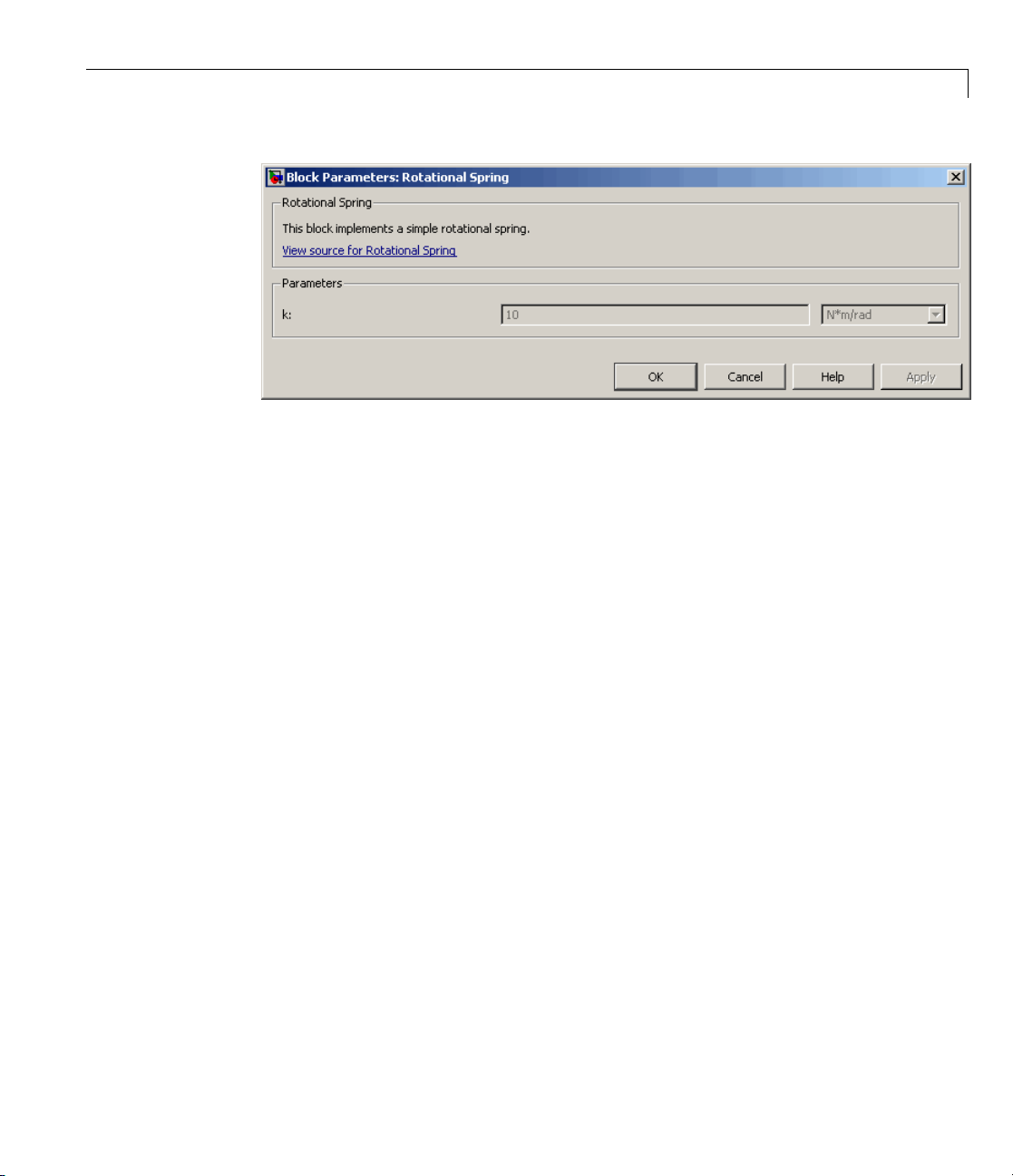
Customizing the Block Name and Appearance
To create a paragraph break in the block description, use a blank commented
line:
% end of one paragraph
%
% beginning of the next paragraph
How to Specify Meaningful Names for the Block
Parameters
You can specify the name of a block parameter, the way you want it to appear
in the block dialog box, as a comment immediately following the parameter
declaration. Itcanbelocatedonthesamelineoronaseparateline. The
comment must begin with the
For example, if you have the following component file:
component spring
%Rotational Spring
% This block implements a simple rotational spring.
...
parameters
k = { 10, 'N*m/rad' }; % Spring rate
end
...
end
this is the resulting block dialog box:
% character.
3-15

3 Using Simscape™ Files in Block Diagrams
How to Customize the Names and Locations of the
Block Ports
Block ports, both conserving and Physical Signal, are based on the nodes,
inputs, and outputs defined in the component file. The default port label
corresponds to the name of the node, input, or output, as specified in the
declaration block. The default location of all ports is on the left side of the
block icon. The ports are spread equidistantly along the block side.
3-16
To control the port label and location in the block icon, add a comment
immediately following the corresponding node, input, or output declaration. It
can be on the same line or on a separate line. The comment must begin with
the
% character and be of the format label:location,wherelabel is a string
corresponding to the i nput port name in the block diagram, and
one of the following strings:
ports either on one side o f the blo ck or on two opposite sides, for example left
and right, or top and bottom. You can omit the location if you w a nt to keep
the default location of the port (on the left side).
You can also leave the port label field empty and specify just the location. In
this case, the port wi ll not have its name displayed. For example, the following
syntax suppresses the port label and locates it on the top of the block icon:
r=fo
If you specify an empty comment string after a node, input, or output
declaration, the corresponding port will not be labelled and will be located on
theleftsideoftheblockicon.
undation.mechanical.rotational.rotational; % :top
left, right, top, bottom.Youcanlocateall
location is

Customizing the Block Name and Appearance
The following are examples of node declarations and the resulting block icons.
Syntax
nodes
r = foundation.mechanical.rotational.rotational;
c = foundation.mechanical.rotational.rotational;
end
nodes
r = foundat
c = foundat
end
nodes
r = foundation.mechanical.rotational.rotational;
c = foundation.mechanical.rotational.rotational; % c:right
end
ion.mechanical.rotational.rotational; % rod
ion.mechanical.rotational.rotational; % case
Block Icon
nodes
r = foundation.mechanical.rotational.rotational; % rod
c = foundation.mechanical.rotational.rotational; % case:right
end
3-17

3 Using Simscape™ Files in Block Diagrams
Syntax
nodes
r = foundation.mechanical.rotational.rotational; % rod
c = foundation.mechanical.rotational.rotational; % :right
end
nodes
r = foundation.mechanical.rotational.rotational; %
c = foundation.mechanical.rotational.rotational; % case:right
end
How to Cus
If the sub
also con
image fi
the icon
package containing the component file (for example,
tains a fi le named
le formats (such as
representing this block in the custom library.
Block Icon
tomize the Block Icon
spring.ssc)
spring.img,whereimg is one of the supported
jpg , bmp,orpng), then that image file is used for
3-18
The fol
•
lowing image file formats are supported:
jpg
• bmp
• png
ere are multiple image files, the formats take precedence in the order
If th
ed above. For example, if the subpackage contains both
list
spri
ng.bmp
, spring. jpg is the image that will appear in the custom library.
spring.jpg and
 Loading...