


SimMechanics™ 3
Reference

How to Contact The MathWorks
www.mathworks.
comp.soft-sys.matlab Newsgroup
www.mathworks.com/contact_TS.html Technical Support
suggest@mathworks.com Product enhancement suggestions
bugs@mathwo
doc@mathworks.com Documentation error reports
service@mathworks.com Order status, license renewals, passcodes
info@mathwo
com
rks.com
rks.com
Web
Bug reports
Sales, prici
ng, and general information
508-647-7000 (Phone)
508-647-7001 (Fax)
The MathWorks, Inc.
3 Apple Hill Drive
Natick, MA 01760-2098
For contact information about worldwide offices, see the MathWorks Web site.
SimMechanics™ Reference
© COPYRIGHT 2001–20 10 by The MathWorks, Inc.
The software described in this document is furnished under a license agreement. The software may be used
or copied only under the terms of the license agreement. No part of this manual may be photocopied or
reproduced in any form without prior written consent from The MathW orks, Inc.
FEDERAL ACQUISITION: This provision applies to all acquisitions of the Program and Documentation
by, for, or through the federal government of the United States. By accepting delivery of the Program
or Documentation, the government hereby agrees that this software or documentation qualifies as
commercial computer software or commercial computer software documentation as such terms are used
or defined in FAR 12.212, DFARS Part 227.72, and DFARS 252.227-7014. Accordingly, the terms and
conditions of this Agreement and only those rights specified in this Agreement, shall pertain to and govern
theuse,modification,reproduction,release,performance,display,anddisclosureoftheProgramand
Documentation by the federal government (or other entity acquiring for or through the federal government)
and shall supersede any conflicting contractual terms or conditions. If this License fails to meet the
government’s needs or is inconsistent in any respect with federal procurement law, the government agrees
to return the Program and Docu mentation, unused, to The MathWorks, Inc.
Trademarks
MATLAB and Simulink are registered trademarks of The MathWorks, Inc. See
www.mathworks.com/trademarks for a list of additional trademarks. Other product or brand
names may be trademarks or registered trademarks of their respective holders.
Patents
The MathWorks products are protected by one or more U.S. patents. Please see
www.mathworks.com/patents for more information.
Revision History
October 2008 Online only New for Version 3.0 (Release 2008b)
March 2009 Online only Revised for Version 3.1 (Release 2009a)
September 2009 Online only Revised for Version 3.1.1 (Release 2009b)
March 2010 Online only Revised for Version 3.2 (Release 2010a)

Block Reference
1
Machines, Bodies, and G rounds ..................... 1-2
Contents
Joints
Assembled Joints
Disassembled Joints
Massless Connectors
Constraints and Drivers
Actuators and Sensors
Force Elements
Interface Elements
Utilities
............................................ 1-2
.................................. 1-2
............................... 1-4
............................... 1-4
.................................... 1-6
................................ 1-6
........................................... 1-7
............................ 1-5
............................. 1-5
iii

Blocks — Alphabetical List
2
Function Reference
3
Configuration Parameters
4
SimMechanics Pane: General ....................... 4-2
SimMechanics Pane Overview
Warn if machine contains redundant constraints
Warn if number of initial constraints is unstable
Mark automatically cut joints
Display machines after updating diagram
Show animation during simulation
Show only port coordinate systems
Default body color (RGB)
Default body geometries
....................... 4-3
........ 4-4
........ 4-6
....................... 4-8
............. 4-10
................... 4-12
................... 4-14
........................... 4-16
............................ 4-18
iv Contents
Index

Block Reference
1
Machines, Bodies, and Grounds
(p. 1-2)
Joints (p. 1-2) Add degrees of freedom
Constraints and Drivers (p. 1-5) Remove degrees of freedom
Actuators and Sensors (p. 1-5)
Force Elements (p. 1-6) Generate interbody forces
Interface Elements (p. 1-6) Interface three-dimensional motion
Utilities (p. 1-7) Miscellaneous useful blocks
Represent machines and bodies
Initiate, impose, and m easure
mechanical m otions
with one-dimensional domains in
Simscape™

1 Block Reference
Machines, Bodies, and Grounds
Body Represent customizable rigid body
Joints
Ground
Machine Environment
Shared Envir
Assembled Joints (p. 1-2) Collocated joints
Disassembled Joints (p. 1-4)
Massless Connectors (p. 1-4)
onment
Represent immo
World
Set up mechani
machine
Connect two m
so that they
environmen
Dislocated joints
Rigidly separated joints
bile point at rest in
cal environment for
echanical components
share same mechanical
t
Assembled Joints
Bearing Represent composite joint with o ne
translational and three rotational
DoFs
1-2
Bush
tom Joint
Cus
ing
esent composite joint with three
Repr
nslational and three rotational
tra
s
DoF
Represent customizable com posite
joint w ith up to three translational
and up to three rotational degrees of
freedom

Joints
Cylindrical
Represent composite joint with one
translational DoF and one rotational
DoF, with parallel translation and
rotation axes
Gimbal
Represent composite joint with three
rotational DoFs
In-Plane Represent composite joint with two
translational DoFs
Planar Represent composite joint with
two translational DoFs and one
rotational DoF, with rotational axis
orthogonal to plane of translational
axes
Prismatic Represent prismatic joint with one
translational degree of freedom
Revolute Represent assembled revolute joint
with one rotational d egre e of freedom
Screw
Represent composite joint with one
translational DoF and one rotational
DoF, with parallel translation
and rotation axes and linear pitch
constraint between translational
and rotational m otion
Six-DoF
Represent composite joint with three
translational and three rotational
DoFs
Spherical
Represent assembled spherical joint
with three rotational degrees of
freedom
Telescoping Represent composite joint with one
translational and three rotational
DoFs
1-3

1 Block Reference
Universal Represent composite joint with two
rotational DoFs
Weld Represent joint with no DoFs
Disassembled Joints
Disassembled Cylindrical
Disassembled Prismatic Represent disassembled prismatic
Disassembled Revolute Represent disassembled revolute
Disassembled Spherical
Represent disassembled cylindrical
joint, with one translational DoF and
one rotational DoF along and about
misaligned axes, with no constraints
joint with one translational degree o f
freedom along misaligned axes
joint with one rotational degree of
freedom about misaligned axes
Represent disassembled spherical
joint with three rotational degrees of
freedom about dislocated pivots
Massless Connectors
Revolute-Revolute Represent composite joint composed
of two revolute primitives spatially
separated by massless connector of
constant length
Revolute-Spherical
Represent composite joint composed
of revolute and spherical primitives
spatially separated by massless
connector of constant length
1-4
Spherical-Spherical
Represent composite joint composed
of two spherical primitives spatially
separated by massless connector of
constant length

Constraints and Drivers
Angle Driver Specify angle between two body axis
Constraints and Drivers
vectorsasfunctionoftime
Actua
Distance Driver
Gear Constraint Constrain rotational motion of two
Linear Driver
Parallel Constraint Constrain body axis vectors of two
Point-Curve Constraint Constrain motion of point on o ne
Velocity Driver
tors and Sensors
Body Actuator Apply f orce or torque to body
Specify distance b etw een two Body
CS origins as function of time
bodies to move along tangent pitch
circles
Specify component of vector
difference of two Body CS origins as
function of time
bodies to be parallel
body to be along curve on another
body
Specify linear combination of the
linear and angular velocities of two
bodies as function of time
sure body motion
Body Sensor
Constraint & Driver Sensor Measure constraint force or torque
Driver Actuator Apply relative motion betw een a pair
Joint Actuator Apply force, torque, or motion to
Mea
between pair of constrained bodies
of constrained bodies through driver
joint primitive
1-5

1 Block Reference
Joint Initial Condition Actuator Apply initial positions and velocities
to primitives of Joint before starting
simulation
Joint Sensor Measure motion of and force or
torque on joint primitive
Joint Stiction Actuator Apply classical friction to joint
primitive
Variable Mass & Inertia Actuator
Force Elements
Body Spring & Damper Model dampe d linear oscillator force
Joint Spring & Damper Model damped linear oscillator force
Interface Elements
Prismatic-Translational Interface Connect prismatic primitive
Vary mass and inertia on body at
specific Body coordinate system as
function of time (not including thrust
force or torque)
between two b od ies
or torque on prismatic or revolute
joint between two bodies
to one-dimensional Simscape
mechanical translational elements
1-6
Revolute-Rotational Interface Connect revolute primitive
to one-dimensional Simscape
mechanical rotational elements

Utilities
Utilities
Continuous Angle Convert discontinuous, bounded
angular output from sensor to
continuous, unbounded angular
output
Mechanical Branching Bar Map multiple sensor or actuator
lines to one sensor or actuator port
on Joint, Constraint, or Driver, or
to one Body coordinate sy stem port
on Body
RotationM
atrix2VR
Convert 3-by-3 rotation matrix to
equivalent VRML form of rotation
axis and angle
1-7

1 Block Reference
1-8

2
Blocks — Alphabetical List

Angle Driver
Purpose Specify angle between two body axis vectors as function of time
Library Constraints & Drivers
Description The Angle Driver block drives axis vectors defined on two Bodies. You
specify fixed base and fixed follower body axis vectors a
Body CS on e ither side of the Driver on each body, then drive the angle
between the body axis vectors as a function of time.
The Angle Driver block specifies the angle θ defined by
cos = | |/(| || |)
aa a a⋅
BF B F
as a function of time: θ = θ(t=0) + f(t). You connect the Angle Driver
to a Driver Actuator block.
The Simulink
time-dependent driving function f(t) and its first two derivatives, as
well as their units. If you do not actuate An gle Driver, this block acts a s
a time-independent constraint that freezes the angle between the two
body axes at its initial value θ(t=0) during the simulation.
®
input signal into the Driver Actuator specifies the
, aFin the
B
2-2
Drivers restrict relative degrees of free dom (DoFs) between a pair of
bodies as specified functions of time. Locally in a machine, they replace
a Joint as the expression of the DoFs. Globally, Driver blocks must
occur topologically in closed loops. Like Bodies connected to a Joint, the
two Bodies connected to a Drivers are ordered as base and follower,
fixing the direction of relative motion.
Caution
If the two axes come close to aligning, that is, if θ approaches zero, the
constraint between the two axes becomes singular, and the simulation
slows down. See “How SimMechanics™ Software Works” and “Handling
Motion Singularities”.

Dialog
Box a nd
Parameters
Angle Driver
You can also connect a Constraint & Driver Sensor to any Driver
measure the reaction forces /torques between the driven bodies.
Connection
Parameters
The dialog has two active areas, Connection parameters and
Parameters.
The base (B)-follower (F) Body sequence determines the sense of positive
motion. Positive rotation is the follower rotating in the right-handed
sense about the rotation axis.
Current base
When you connect the base (B) connector port on the Angle Driver
block to a Body CS Port on a Body, this param eter is automatically
reset to the name of this Body CS. See the following figure, Angle
Driver Base and Follow er Body Connector Ports o n page 2-4.
Current follower
When you connect the follower (F) connector port on the Angle
Driver block to a Body CS Port on a Body, this parameter is
2-3

Angle Driver
automatically reset to the name of this Body CS. See the following
figure, Angle Driver Base and Follower Body Connector Ports
on page 2-4.
Number of sensor/actuator ports
Using this spinner menu, you can set the number of extra
connector ports needed for connecting Driver Actuator and
Constraint & Driver Sensor blockstothisDriver. Thedefaultis
To activate the Driver, connect a Driver Actuator.
Angle Driver Base and Follower Body Connector Ports
Parameters Fixed axis [x y z]
For the Base and Follower bodies, respectively, enter the body
axis vectors. The defaults are
0.
[1 0 0].
2-4
See Al
so
Reference CS
Using the pull-down menu, choose the coordinate system (World,
the base Body CS, or the follower Body CS) whose coordinate
axes the Base and Follower body axis vectors are oriented w ith
respect to. This CS also determines the absolute meaning of
reaction forces/torques at this Driver. The defaults are
raint & Driver Sensor, Driver Actuator, Parallel Constraint,
Const
ity Driver
Veloc
Constraining and Driving Degrees of Freedom” for more on
See “
ricting DoFs with Drivers.
rest
Verifying Model Topology” and “How SimMechanics Software
See “
s” for more on u sing drivers in closed loops.
Work
“Constraints and Drivers” on page 1-5.
See
World.

Bearing
Purpose Represent composite joint with one translational and three rotational
DoFs
Library Joints/Assembled Joints
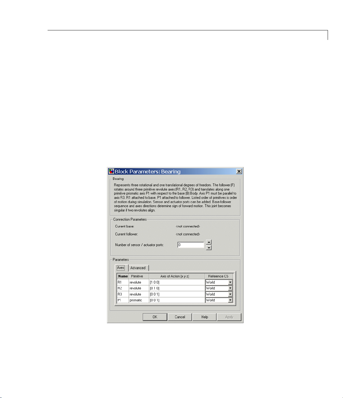
Description The Bearing block represents a composite joint with one translational
degree of freedom (DoF) as one prismatic primitive and three rotational
DoFs as three revolute primitives. There are no constraints among the
primitives. Unlike Telescoping, Bearing represents the rotational DoFs
as three revolutes, rather than as one spherical.
Warning
A joint with three revolute primitives becomes singular if two
or three of the rotation axes become parallel (“gimbal lock”).
The simulation stops with an error in this case.
A joint with three revolute primitives must be configured in the
initial state with the three revolute primitive axes mutually
orthogonal. There are no restrictions on the primitive axes once
the simulation starts, except to prevent any two of the primitive
axes from becoming parallel.
Note Bearings are often represented by one translational and one
rotational DoF. The Bearing block has three rotational degrees of
freedom, rather than one, in order to represent transverse “play” in
the joint.
2-5

Bearing
2-6
Satisfying Joint Requirements
A Joint block represents the relative degrees of freedom between two
bodies, not the bodies themselves.
You must connect any Joint block to two and only two Body blocks, the
base and the follower. All Joints have tw o connector ports for these
connections, defining the direction of joint motion (base to follower).
You connect each side of the Joint block to these Body blocks at a Body
coordinate system (CS) port.
You specify the joint primitive axes, if any, in the Joint d i alog.
mbly Restrictions on Assembled Joints
Asse
s Joint block is assembled and places restrictions on the connected
Thi
yCSs.
Bod
Bearing
• If the Joint has no pri smatic primitives, the origins of the connected
Body CSs on either side of the Joint must be spatially collocated
points, to within assembly tolerances.
• If the Joint has one or more prismatic primitives, the origins of the
connected Body CSs must lie in the span of the prismatic axes:
Dialog
Box a nd
Parameters
Number of Prismatic
Primitives
One Along the prim itive axis
Two
Three
Span of Primitive Ax es
Intheplaneoftheprimitiveaxes
Anywhere in three-dimensional space
2-7

Bearing
The dialog has two active areas, Connection parameters and
Parameters.
Connection
Parameters
The base (B)-follower (F) Body sequence determines the sense of positive
motion. Positive translation is the follower moving in the direction of
the translation axis. Positive rotation is the follower moving around the
rotational axis following the right-hand rule.
Current base
When you connect the base (B) connector port on the Bearing block
to a Body CS Port on a Body, this parameter is automatically reset
to the name of this Body CS. See the follow ing figure, Bearing
Base and Follower Body Connector Ports on page 2-9.
The base Body is automatically connected to the first joint
primitive
Current follower
When you connect the follower (F) connector port on the Bearing
block to a Body CS Port on a Body, this param eter is automatically
reset to the name of this Body CS. See the following figure,
Bearing Base and Follow er Body Connector Ports on page 2-9.
The follower B ody is automatically connected to the last joint
primitive
Number of sensor/actuator ports
Using this spinner menu, you can set the number of extra
connector ports needed for connecting Joint Actuator and Joint
Sensor blocks to this Joint. The default is
R1 in the primitive li st in Parameters.
P1 in the primitive li st in Parameters.
0.
2-8
The motions of prismatic and revolute primitives are specified in
linear and angular units, respectively.

Bearing Base and Follower Bod y Connector Ports
Parameters Switch between the Axes and Advanced tabs.
Axes Tab
Name - Primitive
The primitive list states the names and types of joint primitives
that make up the Bearing block: revolute primitives
and prismatic primitive
Axis of Action [x y z]
Enter here as a three-component vector the directional axes
defining the allowed motions of these primitives and their
corresponding DoFs:
P1.
Bearing
R1, R2, R3,
• Prismatic: axis of translation
• Revolute: axis of rotation
The d efault vectors are shown in the dialog above. The axis is a
directed vector whose overall sign matters.
To prevent singularities and simulation errors, no two of the
revolute axes can be parallel.
Reference CS
Using the pull-down menu, choose the coordinate system (World,
thebaseBodyCS,orthefollowerBodyCS)whosecoordinateaxes
the vector axis of action is oriented with respect to. This CS also
determines the absolute meaning of forces/torques and motion
along/about the joint axis. The default is
World.
2-9
Bearing
Restricted Parameters
When your model is in Restricted editing mode, you cannot modify the
following parameters:
• The Axes (joint primitives) parameters table
The entries on the Axes tab are required. Each DoF primitive in
Bearing has an entry line. Thes e lines specify the direction of the axes
of action of the DoFs that the Bearing represents.
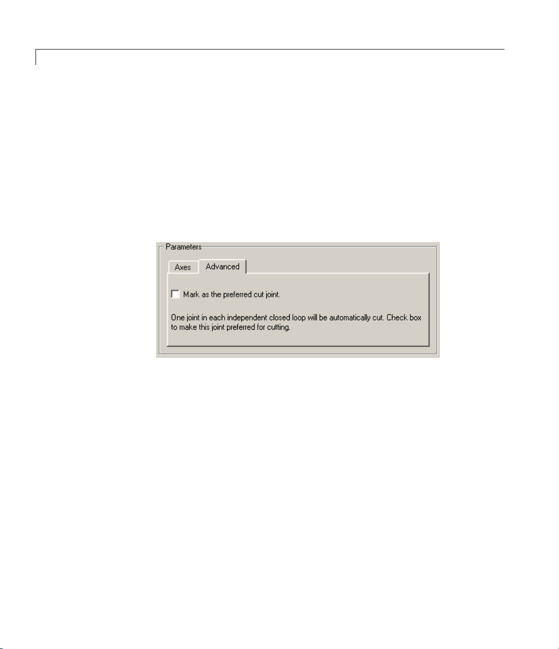
Advanced Tab
2-10
See
Also
The Advanced tab is optional. You use it to control the way
SimMechanics simulation interprets the topology of your schematic
diagram.
Mark as the preferred cut joint
In a closed loop, the simulation internally and automatically cuts
one and only one joint.
If you want this particular joint to be weighted preferentially for
cutting during the simulation, select the check box. The default
is not selected.
hing, Cylindrical, Gimbal, Prismatic, Revolute
Bus

Bearing
See “Modeling D egrees of Freedom” for more on representing DoFs
with Joints.
See “Verifying Model Topology” and “How SimMechanics Software
Works” for more on closed loops and cutting.
2-11

Body
Purpose Represent customizable rigid body
Library Bodies
Description The Body block represents a rigid body with properties you customize.
The representation that you specify must include:
• The body’s mass and moment of inertia tensor
• The coordinates for the body’s center of gravity (CG)
• One or more Body coordinate systems (CSs)
The representation can also include optional body geometry and color
information for visualization.
A rigid body is defined in space by the position of its CG (or center of
mass) and its orientation in some defined coordinate system.
Setting Body Initial Cond itions The initial position and orientation
of a body are set by the entries in its Body dialog that define the body’s
home configuration. These initial conditions remain unchanged, unless,
with a Joint Initial Condition Actuator, you change the initial conditions
of the Joint(s) connected to the Body prior to starting the simulation,
or you actuate the Body with a Body Actuator. The imposition of
additional initial conditions defines the initial configuration of the body.
2-12
Defining a Body with Mass, Coordinate System, and
Visualization Properties
You must enter properties for a SimMechanics body in two sets, mass
properties and coordinate system properties.Athirdset,visualization
properties,isoptional.
Mass Properties
The mass properties are defined by the body’s mass and inertia tensor.

Body
• The mass is the body’s inertia and controls the translational
acceleration of the CG in response to an a pplied force.
• The inertia tensor measures the distribution of mass density in the
body and controls the rotational acceleration of the body about the
CG in response to an applied torque.
• The components of the inertia tensor control the initial orientation of
the body and are always interpreted as being in the CG CS axes. The
orientation of the CG CS axes with respect to another CS external to
the body (the World CS, a CS on a Ground, or a CS on another Body)
then determines the orientation of the body with respect to other
bodies or with respect to World.
• The body’s inertia tensor defines its principal axes and moments
and its equivalent ellipsoid, one of the standard shapes available
for displaying a body in space.
Coordinate System Properties
The coordinate system properties are defined by the body’s Bod y CSs.
• The CS with its origin at the CG is required. The CG point specifies
both the initial position of the whole body and the origin of the CG
CS. You must also orient the CG CS axes.
• You can place one or more additional Body CSs on a body. The Body
dialog requires at least one. You must define each Body CS by the
position of its origin and the orientation of its CS axes.
• Each connection of a Joint, Constraint/Drive, Actuator, or Sensor
block to a Body requires an anchor point on the Body. This anchor
point is one of the Body CS origins.
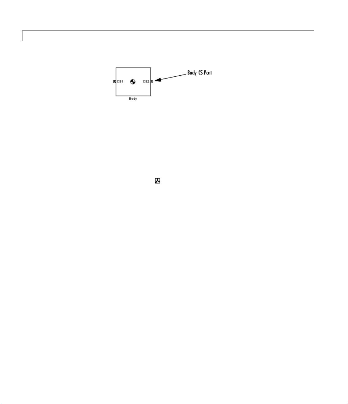
• Body CSs on the block available for connections are shown by Body
CS ports
CS on the b lock sides.
• The set of a body’s Body CS origins (including the CG CS) defines
the body’s convex hull, one of the standard shapes available for
displaying a body in space.
on the sides of the block. You can show or hide each Body
2-13

Body
Visualization Properties
The visualization properties of a body include its color and geometry
(surface size and shape).
• As a default, the machine of which the Body is a member determines
these visualization properties.
• You can partly or completely override these defaults with custom
settings for an individual Body.
Default Initial State of a Body
These two properties determine a body’s initia l position and orientation:
• The position of a body’s CG sets its initial position.
• The body’s inertia tensor components (in the CG CS) and the
orientation of the CG CS axes with respect to other CSs in the
machine set its initial orientation.
The initial conditions of a machine can be changed with Joint Initial
Condition Actuator block s before you start a simulation. If you do not
change the initial state of a Body be fore simulation, SimMechanics
simulation sets its initial position and orientation to its Body dialog
entries, defining the body’s home configuration. SimMechanics
simulation also sets the Body’s initial linear/angular velocities to zero
in this case.
2-14

Dialog
Box a nd
Parameters
Body
The dial
Positi
Visual
Restri
When y
follo
• The P
• The O
og has two active areas, Mass properties and the set of tabs,
on and Orientation for Body coordinate systems, as well as
ization.
cted Para meters
our m odel is in Restricted editing mode, you cannot modify the
wing parameters:
osition Body coordinate systems tab
rientation Body coordinate systems tab
2-15

Body
Mass
Properties
Body
Coordinate
Systems
Mass
Enter the mass of the body in the first field and choose units in
the pull-down menu to the right. The mass must be a positive,
real number or MATLAB
are
1 and kg (kilograms).
Inertia
Enter the inertia tensor (with respect to the Body CG CS axes)
in the first field and choose units in the pull-down menu to the
right. The tensor must be a 3-by-3 real, symmetric matrix. The
default tensor is
zero tensor
is
2
kg-m
(kilograms-meters2).
eye(3), the MATLAB 3-by-3 identity matrix. A
zeros(3,3) defines a point mass. The units default
®
equivalent expression. The defaults
Configuring a Body Coordinate System
You set up Body CSs on the Position and Orientation tabs:
• The default co nfiguration consists of three Body CSs: the re quired CG
CS attached to the body’s CG and two other optional Body CSs, called
“CS1” and “CS2,” for connecting Joints, Constraints, or Drivers.
• You can configure the CG CS but not delete it. You also cannot create
additional CG CSs, although you can duplicate the CG CS with a
different name. (See more about Body coordinate systems controls
following.)
2-16
• The other CSs can be configured or deleted as you want, keeping
at least one.
• Configuring a Body CSs requires two groups of steps:
- Positioning the Body CS origin in the Position tab
- Orienting the Body CS axes in the Orientation tab
• Defining Body CSs requires referring to other, pre-existing CSs in the
model. In a given Body block, you can refer to Body and Grounded
CSs in three ways. The references must be to:
- World

- Other Body CSs on the same body
- The Adjoining CS, the coordinate system on a neighboring body
or ground directly connected to the selected Body CS by a Joint,
Constraint, or Driver
• You must directly or indirectly define all Body CSs by reference to
a Ground or to World. With indirect reference, you specify a Body
CS relative to another CS and so on, in a chain of references that
ultimately ends in a Ground or World. The CS reference chains of the
Position and Orientation tabs can be different. The CS reference
chains must not form a closed cycle.
Body
• Switch between the Position and Orientation tabs.
Each Body CS is labeled with a name,
CS2,etc.,foradditionalCSs.
Configuring the Position Fields
The Position fields for each Body CS specify the position of that CS’s
origin as a trans l ation vector:
• The numerical components of the vector carry units.
• The translation vector’s components are oriented with respect to
another set of CS axes.
• The origin is displaced from the origin of another, pre-existing CS in
your machine by this translation vector.
CG for the CG CS, and CS1,
2-17

Body
Highlight each Body CS to configure it.
Origin Position Vector [x y z]
Enter the translation vector that defines the position of the Body
CS’s origin.
The entry for the CG CS origin positions the entire body.
Units
Choose linear units for the translation vector. The default is m
(meters).
2-18
Translated from Origin of
In the pull-down menu, choose the other, pre-existing CS in your
machine that defines the starting point for the translation vector.
The choices are
this Body. The ending point of the translation vector is this Body
CS’s origin.
For the CG CS, the default starting-point CS is
additional Body CSs (CS1, CS2, etc.), the default starting point
CS is this Body’s
Components in Axes of
In the pull-down menu, choose the CS whose axes define the
orientation of the translation vector’s components. The choices
are
World, Adjoining, and the other Body CSs on this Body. The
World, Adjoining, and the other Body CSs on
World.Forthe
CG.

Body
translation vector’s components are measured relative to the axes
of the CS chosen in this column.
For the CG CS, the default orientation CS is
additional Body CSs (CS1, CS2, etc.), the default orientation CS
is this Body’s
CG.
World.Forthe
Configuring the Orientation Fields
The Orientation fields for each Body CS specify the orientation of that
CS’s triad of axes as a rotation:
• The orientation vector specifying the rotation vector has three
components.
• The numerical components of the vector carry units.
• The rotation is oriented with respect to some other, pre-existing set
of CS coordinate axes in your machine.
• The orie ntation vector’s components are interpreted in the convention
of a rotation representation.
Highlight each Body CS to configure it.
Orientation Vector
Enter the components of the rotation that defines the orientation
of the Body CS’s axes. The geometric meaning of these components
is determined by the Specified Using Convention column.
2-19

Body
The required entry for the CG CS orients the CG CS axes.
Together with the Inertia tensor entry in Mass properties,the
CG CS axes orient the whole body with respect to another CS
in your machine.
Units
Choose angular units for the rotation, degrees or radians. The
default is
deg (degrees).
Relative CS
In the pull-down menu, choose one of the other pre-existing CSs
inyourmachinetodefinethestartingorientationfortherotation.
The choices are
World, Adjoining, and the other Body CSs on
this Body.
Specified Using Convention
In the pull-down menu, choose the representation type for the
rotation:
Rotation Type Orientation Vector Com ponents
Quaternion
3x3Transform
Euler
[
n
*sin(θ/2) ny*sin(θ/2)
x
n
*sin(θ/2) cos(θ/2)]
z
3-by-3 orthogonal rotation matrix R
Rotation angles about sequence
of three axes defining
Euler angle convention
[first-axis second-axis third-axis]
2-20
Rotation Conventions
There are three conventions in a Body block for representing rotations.
See “Body Motion in SimMechanics Representations” and “Body
Orientation in SimMechanics Representations” to learn more about
rotations.

• Euler
The Euler angle convention specifies the rotation of the Body CS axes
by rotating about three axes in a sequence. The components of the
1-by-3 row vector are the angles of rotation about those three axes,
respectively in sequence, in degrees or radians.
Body
For example,
Euler X-Y-Z means rotate about the original X axis,
then about the first intermediate Y axis, and then about the second
intermediate Z axis. Another example:
Euler X-Z-Y means rotate
about the original X axis, then about the first intermediate Z axis,
and then about the second intermediate Y axis.
•
3-by-3 Transform
The transform convention specifies the rotation as a dimensionless
3-by-3 orthogonal rotation matr ix. The inverse of an orthogonal
matrix R is equal to its transpose: R
-1
= RT.
The columns of R are the (x,y,z) unit vectors of the Body CS axes.
The units menu is inactive.
Quaternion
•
Thequaternionconventionspecifiestherotationinangle-axisform
as a dimensionless 1-by-4 row vector:
[nx*sin(θ/2) ny*sin(θ/2) nz*sin(θ/2) cos(θ/2)]
n =(nx,ny,nz) is a three-component vector of unit length: n·n = n
2
+ n
2
+ n
z
=1.
y
The unit vector n specifies the axis of rotation. The rotation angle
about that axis is θ and follows the right-hand rule.
2
x
Managing the Body Coordinate Systems List
The Body coordinate system controls (see the following figure, Body
Coordinate Systems Controls on page 2-23) allow you to add, reorder,
and delete Body CSs on a Body block.
2-21

Body
To add a Body CS to the list:
1 Highlight an existing Body CS in the list.
2 Click the Add button (see the following figure, Body Coordinate
Systems Controls on page 2-23).
A new Body CS appears immediately below the Body CS you
highlighted. New Body CSs are named in sequence after the current
ones: CS3, CS4, etc.
To change the position of a Body CS in the list:
1 Highlight the Body CS whose position you want to change.
2 Click on the Up or Down button (see the following figure, Body
Coordinate Systems Controls on page 2-23) until the Body CS is
where you want it.
To delete a Bo dy CS from the list:
2-22
1 Highlight the Body CS you want to delete.
You cannot delete the Body’s CG CS or the last one of the non-CG
CSs.
2 Click on the Delete button (see the following figure, B ody Coordinate
Systems Controls on page 2-23).
The Body CS you highlighted disappears.

Body Coordinate Systems Controls
Body
Managing Body CS Ports on a Body Block
Connecting a Joint, Constraint, Driver,Actuator,orSensorblocktoa
Body block requires an existing and configured Body CS on that Body:
• These other blocks define, constrain, impart, and measure the motion
of bodies with respect to the origin and coordinate axes of Body CSs.
Connect each of these blocks to a Body CS with a connection line.
• The actual connection line running from the other block to the Body
block must be anchored to a displayed Body CS Port
the Body block in the model window.
onthesideof
2-23
Body
• A displayed Body CS Port on a Body block indicates a Body CS with
the displayed name configured internally within the Body block.
• Not all the Body CSs configured inside a Body block need to be
displayed, however.
See the preceding figure, Body Coordinate Systems Controls.
Show Port
Select this check box for any Body CS to create a corresponding
Body CS Port
that line in the Body CS list is now accessible for connection to
other blocks.
onthesideoftheBodyblock. TheBodyCSon
2-24
Clear this check box to remove the Body CS Port corresponding to
that Body CS on that line in the list.
The defaults are not selected for
To apply your choices to the displayed Body block, click Apply.
Port Side
From the pull-down menu, choose which side of the Body block
you want the Body CS Port for that Body CS to be placed on,
Left or Right.
The defaults are
To apply your choices to the displayed Body block, click Apply.
Left for CG and CS1 and Right for CS2.
CG, selected for CS1 and CS2.
Body
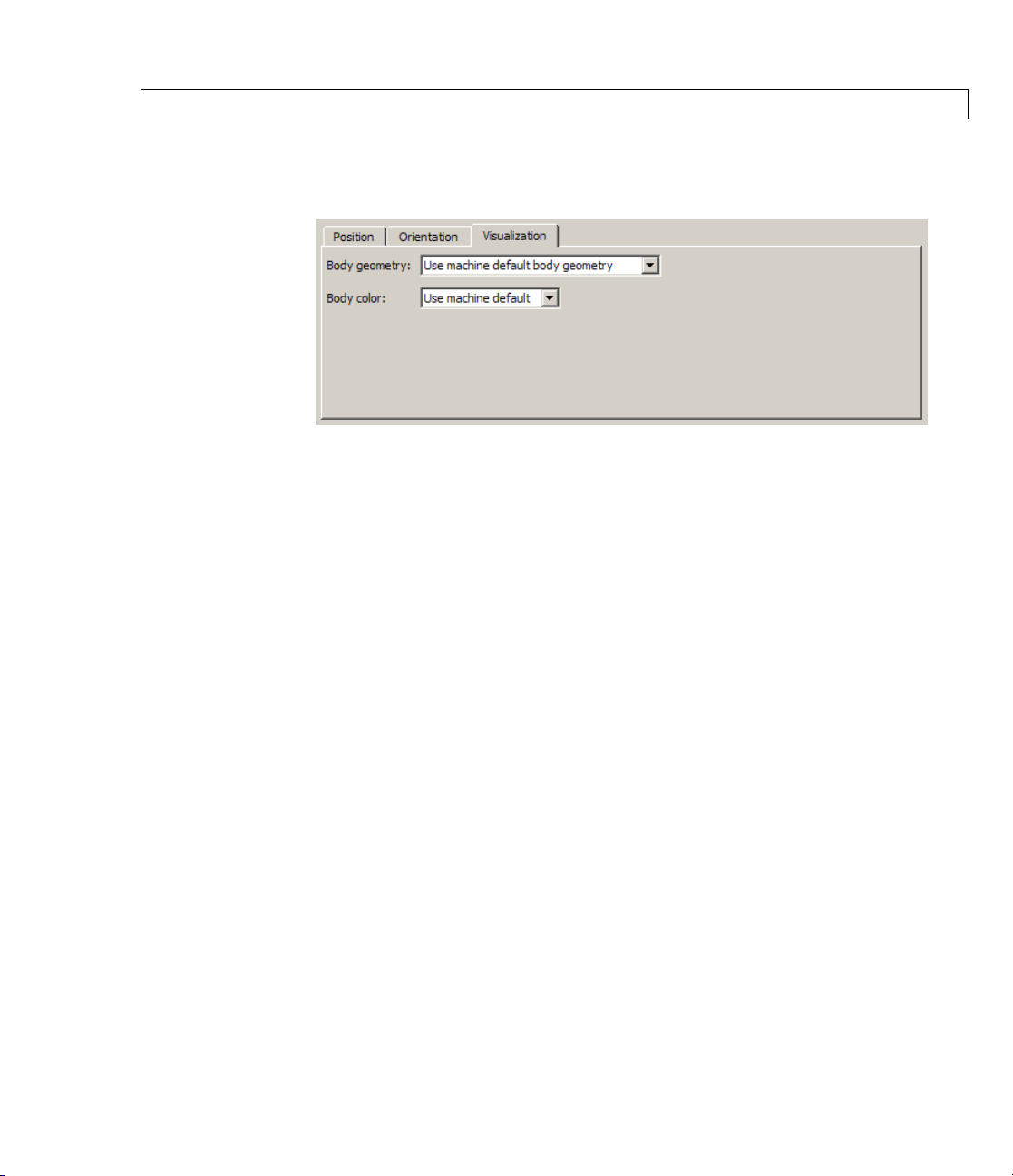
Visualization
Properties
Default Settings
Visualization settings for a body consist of its
• Body geometry (surface shape)
• Color
The visualization window uses thesesettingstodisplaythebody. By
default, a body inherits the visualization settings of the machine to
which it is connected.
Customi
You can c
menus.
zing the Body Visualization Settings
hange the visualization defaults individually with these
Body ge
From th
•
•
•
•
ometry
epull-downmenu,chooseabodysurfaceshape:
Use ma
Conve
Equi
equi
Exte
Ext
chine default body geomet ry
x hull from Body CS locations
valent ellipsoid from mass properties
valent ellipsoids
rnal graphics file
ernal Graphics File” on page 2-26)
(see “Specifying and Configuring an
(default)
for convex hulls
for
2-25
Body
Body color
From the pull-down menu, choose a body color:
•
Use machine default (default)
Use color palette (see “Specifying a Color from the Color
•
Palette” on page 2-27)
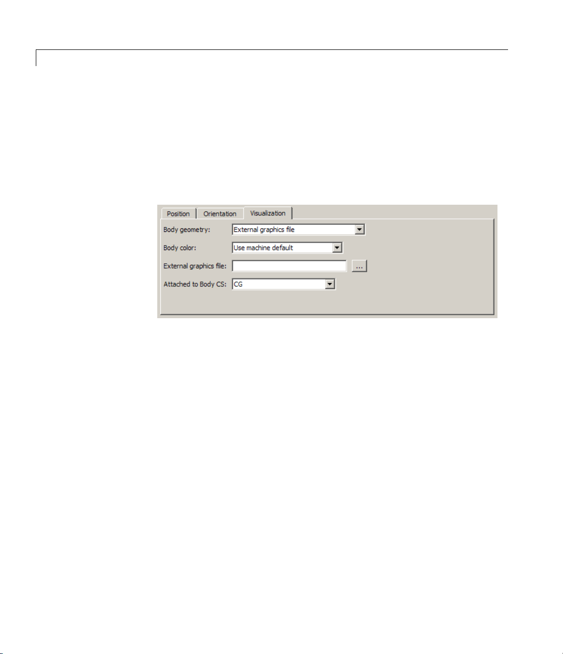
Specifying and Configuring an External Graphics File
2-26
If you cho
pull-do
Externa
Attac
ose
wn menu, you must specify some additional information.
l graphics file
In the fi
You can
... but
hedtoBodyCS
In the
graph
This
he body geometry. Geometric measurements in the graphics
for t
are interpreted in the units associated with this Body CS.
file
External graphics file in the Body geometry
eld, specify the graphics file.
search for files on your file system by clicking the b row se
ton.
pull-down menu, specify which Body CS to attach the
ics to. Your Body CS list is specified by the Position tab.
Body CS serves as the reference origin and coordinate ax es

Body
Requirements for External Body Geometry Files
Custom body visualization requires a body geometry graphics file in the
stereolithographic (STL) format. It supports both binary and ASCII
types of the STL format.
See the visualization chapters of the SimMechanics Visualization and
Import Guide for a complete discussion of graphics files for specifying
body geometries.
Caution
In order for custom visualization to work, this STL file must be either:
• On your MATLAB path.
• In your MATLAB present working folder.
• Specified with complete path in the Body dialog.
Otherwise, visualization reverts to the default body geometry.
Specifying a Color from the Color Palette
If you choose Us e color palette in the Body color pull-down menu,
the color palette button appears to the right of the menu. Click the color
palette button to select a color for the body.
2-27

Body
See Also Body Actuator, Body Sensor, Ground, Machine Environment,
Mechanical Branching Bar
See the relevant entries in the Glossary: adjoining CS, axis-angle
rotation, body, Body CS , center of gravity (CG), convex hull, coordinate
system (CS), equivalent ellipsoid, Euler angle s , inertia tensor, mass,
principal axes, principal inertial moments, quaternion, right-hand rule,
and rotation matrix.
Setting Up and Configuring Bodies in Models
See “Representing Motion” for more details about representing body
position and orientation.
See “Modeling Grou nds and Bodies”, “Creating Body CS Ports”, and
“About SimMechanics Visualization” for more on setting up Bodies in
machines.
See “Applying Motions and Forces” for setting general initial conditions
(positions and velocities) of DoFs in a machine.
Visualizing Bodies
2-28
For more about configuring visualization for simulation, see “Starting
Visualization and Simulation”. For information about machine and
body visualization, including default and custom body geometries and
colors, see the SimMechanics Visualization and Import Guide.

Body Actuator
Purpose Apply force or torque to body
Library Sensors & Actuators
Description The Body Actuator block actuates a Body block with a generalized force
signal, representing a force/torque applied to the body:
• Force for translational motion
• Torque for rotational motion
The generalized force is a function of time sp ecif ied by a Simulink
input signal. This signal can be any Simulink signal, including a signal
feedback from a Sensor block.
The Body Actuator applies the actuation signal in the reference
coordinate system (CS) specified in the block dialog.
The inport is the Simulink input signal. The output is the connector
port you connect to the Body block you want to actuate.
Tip Carefully distinguish the Body Actuator from the Driver blocks:
• The Body Actuator block applies generalized forces to one body in
a specified reference CS.
• The Driver blocks drive relative degrees of freedom between pairs of
bodies.
Other Ways to Actuate Bodies
The Body Actuator block actuates a Body with force/torque signals only .
To actuate a Body with motion signals or initial conditions, or to drive
the relative degrees of freedom between a p air of Bodies , see “Actuating
a Joint” and “Joint Actuator Example: Body Driver”.
The
mech_body_driver model from the Demos library shows how to
drive the relative DoFs between a pair of bodies. To actuate one body
2-29

Body Actuator
Dialog
Box a nd
Parameters
alone, use this model and replace the second Body block with a Ground
block. To set body initial conditions, replace the second Body block with
a Ground block and the Joint Actuators with Joint Initial Condition
Actuators.
Thedialoghasoneactivearea,Actuation.
Actuation With respect to CS
Inthepull-downmenu,choosethecoordinatesystem(CS)in
which the actuating force/torque is interpreted: either the
(Body CS)
Absolute (World).
Generalized Forces
You can apply a force, a torque, or both generalized forces to a body.
If you apply both, you need to bundle the torque and force vectors into a
6-component signal, in the order shown in the dialog.
2-30
Local
to which the Actuator is connected or the default

Applied torque
Select the check box if part or all of the actuating signal is a
rotational torque. The default is not selected. The Simulink
torque input is a 3-component bundled signal.
In the Units pull-down menu, choose units for the actuating
torque. The default is
Applied force
Select the check box if part or all of the actuating signal is a
translational force. The default is selected. The Simulink force
input is a 3-component bundled signal.
In the Units pull-down menu, choose units for the actuating force.
The default is
N (newtons).
N*m (newton-meters).
Example Here is a Body Actuator connected to a Body:
Body Actuator
See
Also
You must connect the Body Actuator to the Body at one of that Body’s
attached Body CSs, at the corresponding Body CS Port. The actuation
signal acts on the Body at that Body CS’s origin.
y, Body Sensor, Driver Actuator, Joint Actuator, Joint Initial
Bod
dition Actuator, Mechanical Branching Bar
Con
2-31

Body Actuator
See “Body Motion in SimMechanics Representations” for more details
on Body coordinate system rotations.
See “Actuating a Joint” and “Joint A ctuator Example: Body Driver”.
See “Machines, Bodies, and Grounds” on page 1-2 and “Constraints
and Drivers” on page 1-5.
In Simulink, see the Signal Routing Library and the Sources Library.
2-32

Body Sensor
Purpose Measure body motion
Library Sensors & Actuators
Description The Body Sensor block senses the motion o f a body represented by
a Body block. You connect the BodySensortoaBodycoordinate
system (CS) on the Body whose motion you want to sense. The sensor
specifically measures the motion of the origin of this Body CS.
The Body Sensor measures the components o f translational and
rotational motion in any combination of:
• Translational position, velocity, and acceleration vectors. The
position vector has its tail at the World CS origin.
• Rotational orientation (a 3-by-3 rotation matrix R)andangular
velocity and acceleration vectors
In the block dialog, you choose the reference coordinate system (CS)
axes in which these components are represented.
The input is the connector port connected to the Body being sensed. The
outport is a set of Simulink signals or one bundled Simulink signal of
the selected matrix and/or vector components.
Body Position-Orientation and the Home Configuration
The Body Sensor block can measure the position and/or orientation of
a body. It measures these relative to the home configuration of the
machine, the machine state before the application of initial condition
actuators and assembly of disassembled joints. Thus the Body Sensor
includes the effect of the latter, which act before the simulation starts.
Defining Coordinate Representations and Body Orientation
A body’s orientation rotation matrix R relates the components of the
same vector v as measured in the inertial W orld CS and in the Body
CS by v
components measured in the World CS. The column vector v
vector v’s three components measured in the Body CS.
=[RT]·vW. The column vector vWlists the vector v’s three
b
b
lists the
2-33

Body Sensor
Dialog
Box a nd
Parameters
The columns of the rotation matrix R are the components of the Body
CS unit basis vectors measured w ith respect to the World axes.
See “Body Motion in SimMechanics Representations” and “Body
Orientation in SimMechanics Representations” for more details on
representing body position and orientation, rotation matrices, and
angular velocity.
The dia
log has one active area, Measurements.
Measurements With respect to CS
In the pull-down menu, choose the coordinate system in which the
body motion components are represented: either the
CS)
World).
(
2-34
Local (Body
to which the Sensor is connected or the default Absolute

Body Sensor
In the Absolute case, the rotation matrix R and the motion
vectors have components represented in the inertial World CS
axes. In the
premultiplied by the body’s inverse orientation rotation matrix
-1
R
= RT.
Each vector measurement is a row vector in the Simulink output
signal. The selected signals are ordered in the same sequence
as the dialog.
Select the check box for each of the possible measurements you want
to make:
• Translational motion: Position, Velocity,andAcceleration
vectors: r, v =dr/dt, and a =dv/dt, respectively.
• Rotational motion: Angular velocity and Angular acceleration
vectors and Rotation matrix:
- The Rotation matrix is the 3-by-3 orthogonal rotation matrix R:
Local case, the same body motion components are
RRR
⎛
11 12 13
⎜
RRR
21 22 23
⎜
⎜
RRR
31 32 33
⎝
representing rotational orientation and satisfying RTR = RRT= I.
The components are output columnwise as a 9-component row
vector: (R
, R21, R31, R12, ... ).
11
⎞
⎟
⎟
⎟
⎠
- If you choose the With respect to coordinate system as
Absolute (World, the Rotation matrix measures the body’s
rotational orientation with respect to the World CS. Recall
the relationship of vector components in the World and bo dy
coordinate axes, v
= R]·vb.
W
- If you choose the With respect to coordinate system as Local
(Body CS)
matrix R
,theRotation matrix returns the 3-by-3 identity
T
R = I.
2-35

Body Sensor
- The angular velocity is ω
+(dR/dt)*R
T
=-R*(dRT/dt), and ε is the permutation symbol. The
= (1/2)Σikε
j
, where the matrix Ω =
ijkΩik
angular acceleration is α =dω/dt.
In the Units pull-down menus, choose the units for each of the
measurements you want:
• Translation: the defaults are
2
m/s
(meters/second2), respectively, for Position, Velocity,and
m (meters), m/s (meters/second), and
Acceleration.
• Rotation: the defaults are
deg/s (degrees/second) and deg/s
(degrees/second2), respectively, for Angular velocity and Angular
acceleration.TheRotation matrix is dimensionless.
Output selected parameters as one signal
Select this check box to convert the output signals into a single
bundled signal. The default is selected. If you clear it, the Body
Sensor block will grow as many Simulink outports as there are
active signals selected, one port for each selected signal.
If the check box is selected, the Simulink signal out has all the
active (selected) signals ordered into a single row vector, in the
same order you see in the dialog. Nonselected components are
removed from the vector signal.
2
2-36
The sensor outputs are ordered and labeled as follows.
Body Sensor Output Signal Label
Position
Velocity
Angular velocity
Rotation matrix
Acceleration
Angular velocity
p
v
av
[R]
a
aa
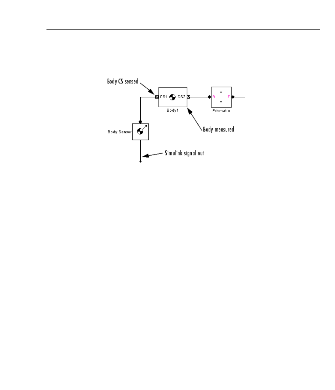
Example Here is a Body Sensor connected to a Body:
Body Sensor
You must co
ports. The
nnect the Body Sensor to the Body at one of its Body CS
Sensor measures the motion of that Body CS.
See Also Body, Body Actuator, Constraint & Driver Sensor, Joint Sensor,
Mechanical Branching Bar
See “Kinematics and the Machine’s State of Motion”, “Body Motion
in SimMechanics Representations”, and “Body Orientation in
SimMechanics Re pre sentations” for more details on representing body
position and orientation.
See “Sensing Motions and Forces”.
See the relevant entries in the Glossary about body orientation:
axis-angle rotation, Euler angles, rig ht-hand rule, and rotation matrix.
In Simulink, see the Signal Routing Library and the Sinks Library.
2-37

Body Spring & Damper
Purpose Model damped linear oscillator force between two bodies
Library Force Elements
Description The Body Spring & Damper block models the force of a damped spring
acting between two bodies. By Newton’s third law, the spring applies
equal and opposite forces to the two bodies. You can use this Force
Element b lock to model any linear (Hooke’s law) force with constant
coefficients that acts between a pair of bodies.
You connect a Body Spring & Damper between two Body coordinate
systems (CSs), each on one body. The vector between the Body CSs
defines the direction and length of the spring. One of the Bodies can
be a Ground.
Caution
The spring and the damper forces act only along the axis connecting
the two Body CSs.
2-38
The Body Spring & Damper has no degrees of freedom (DoFs ).
Grounding the Connected Submachines
The Body Spring & Damper block contains a Shared Environment
block. The submachines connected to either side of this block constitute
a single composite machine that requires exactly one M achine
Environment block, but at least one Ground for each submachine.
Referencing Coordinate Systems on the Connected Bodies
The Body Spring & Damper block is not a Joint and cannot propagate
adjoining coordinate systems fromaBodyononesidetoaBodyonthe
other side.
One Body is connected to one side of the Body Spring & Damper at one
of that Body’s CSs. If you attempt to define that CS in terms of the
adjoining CS (the connected CS of the other Body connected to the other
side), the first Body cannot detect the connected CS of the second body.

Body Spring & Damper
IfyouneedtodefineadjoiningCSsoneithersideofaBodySpring&
Damper, add a Joint block in parallel with the spring-damper.
Adding Joints in Parallel to the Body Spring & Damper
To repres ent the DoFs of one body with respect to the other, either
• Connect one or more Joints in series with the Bodies.
• Create additional Body CSs on each body and connect them with a
Joint in parallel with the Body Spring & Damper. To create parallel
grounds, insert additional Ground blocks.
You can add m ore Joint blocks between the Bodies to represent one,
two, or three prismatic primitives. Use Prismatic blocks or a Custom
Joint block to accomplish this.
Body Spring and Damper Force Law
YouconnectthisblocktoeachBody,A or B, at a Body coordinate system
(CS). If r
position vector connecting them is r = r
is |r|. The relative velocity is v = dr/dt. Then the vector force that
body A exerts on body B is
and rBare the positions of these Body CSs, the relative
A
- rA. The distance of separation
B
F r rr vrrr=⋅−− −kr b(| | )( / | |) ( )( /| | )
0
2
The first term represents the spring or linear displacement force.
The second represents the damper or velocity dissipation force, which
acts only along the direction of r. Thus the damper is equivalent to a
dashpot, not a viscous medium.
You specify
• The spring constant k. A stable s pring requires k >0.
• The natural spring length (offset) r
. The natural length is the length
0
of the s pring with no forces acting on it and physically m ust be
nonnegative: r
0
≥ 0.
2-39

Body Spring & Damper
• The damping constant b. Adampingrepresentingdissipationand
respecting the second law of thermodynamics requires b ≥ 0. You can
use a negative b to represent energy pumping.
Body Spring and Damper Force in Singular Cases
Caution In certain cases, the force formula breaks down, and the block
uses special-case rules to determine the spring-damper force.
To avoid singularities in the initial state of motion, be sure to set the
bodies’ initial conditions of position and velocity to physically sensible
values.
Singular cases include the following:
• If both r
become singular. The spring force is reprojected along the velocity
vector. That is, v/|v|replacesr/|r| in both terms of the force law,
once in the f irst term and twice in the second. If the state r = 0 does
not persist for more than an instant, this replacement has no effect
on the motion.
• If r
undefined. The simulation stops with an error.
and v ≠ 0, and r = 0 at some instant, both terms in the force
0
≠ 0, and both r and v = 0 at some instant, the force direction is
0
2-40
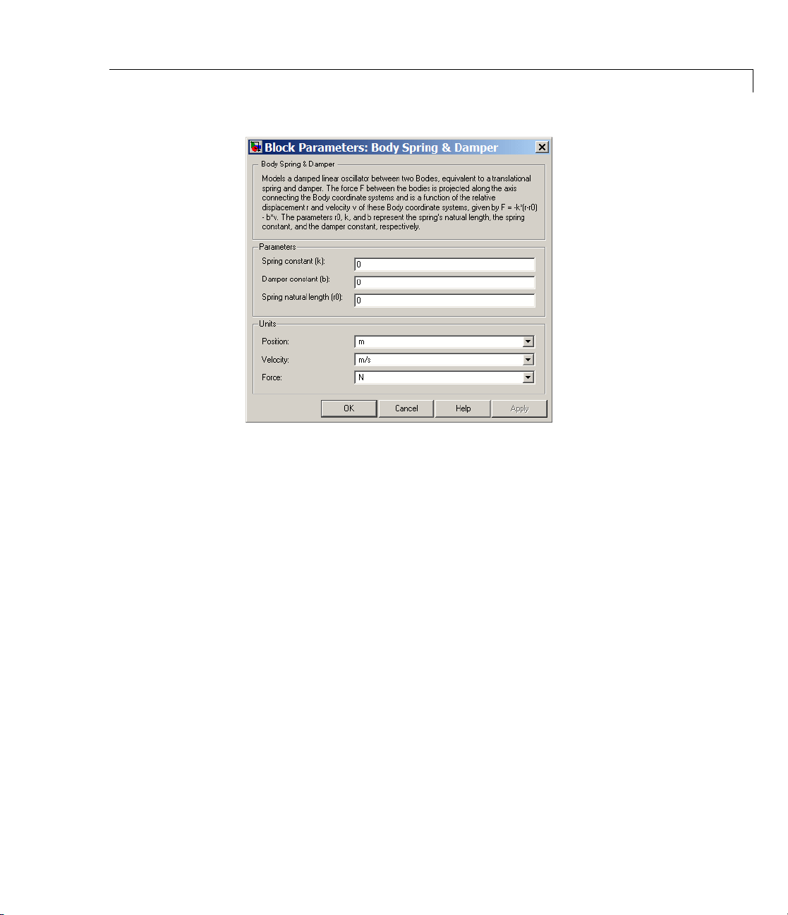
Dialog
Box a nd
Parameters
Body Spring & Damper
Thedialoghastwoactiveareas,Parameters and Units.
Tunable Parameters
All of this block’s fields are tunable during simulation. See the Simulink
documentation for more information about tunable parameters.
Parameters Spring constant (k)
Enter the linear spring force constant k. The default is
The units for k are derived implicitly from your choice of position
and force units.
Damper constant (b)
Enter the linear damping force constant b. The default is
The units for b are derived implicitly from your choice of velocity
and force units.
Spring natural length (r0)
Enter the spring’s natural length (offset) r
0.
.Thedefaultis0.
0
0.
2-41
Body Spring & Damper
Units Position
In the p ull-down menu, choose units for the relative position
vector r.Thedefaultis
Velocity
Inthepull-downmenu,chooseunitsfortherelativevelocity
vector v. The default is
Force
In the pull-down menu, choose units for the spring-damper force
F acting between the bodies. The default is
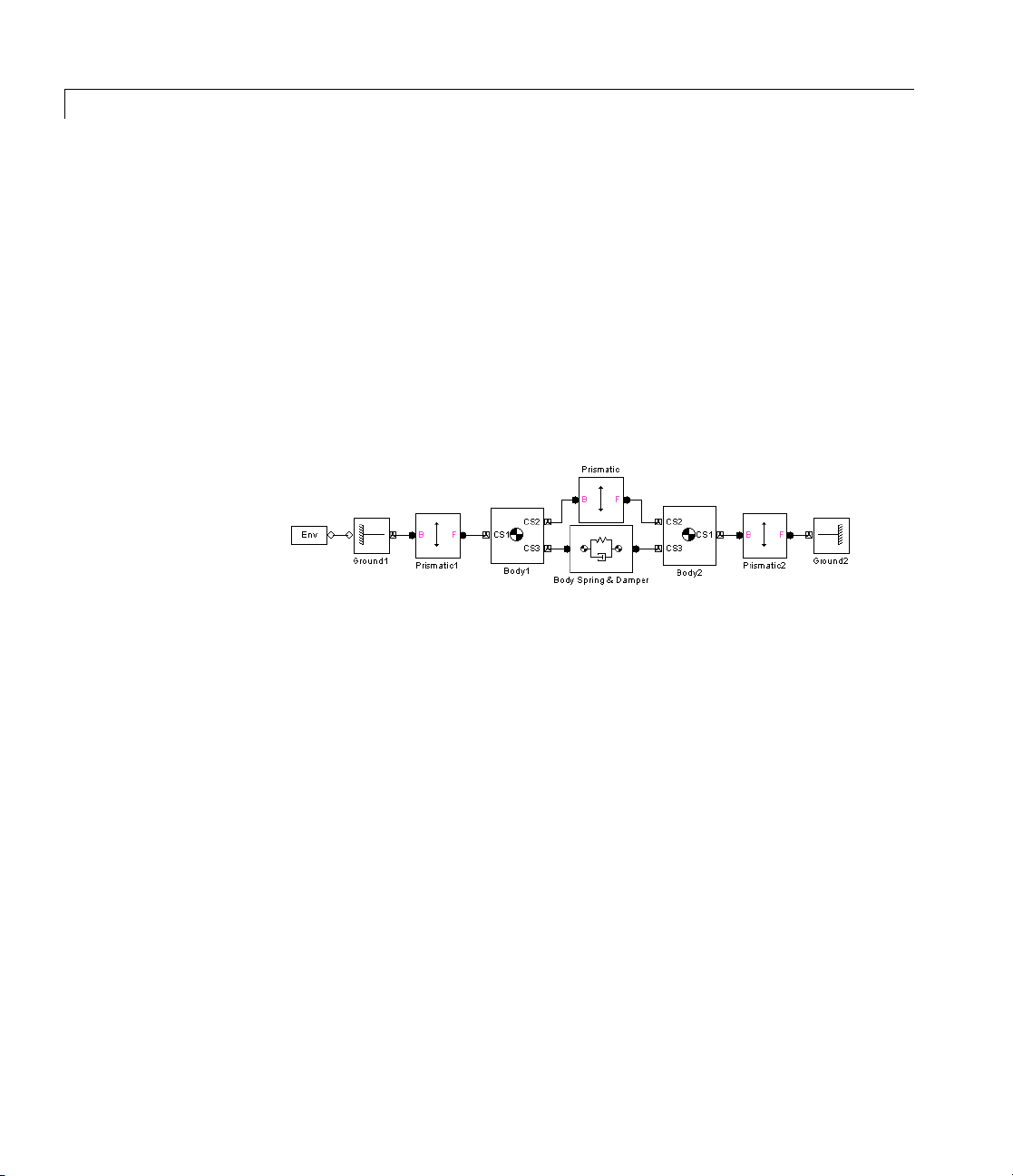
Example This is a simple but representative use of the Body Spring & Damper.
m (meters).
m/s (meters/second).
N (newtons).
See Also Body, Body Actuator, Body Sensor, Custom Joint, Ground, Joint Spring
& Damper, Machine Environment, Prismatic, Shared Environment
See “Adding Internal Forces”.
2-42

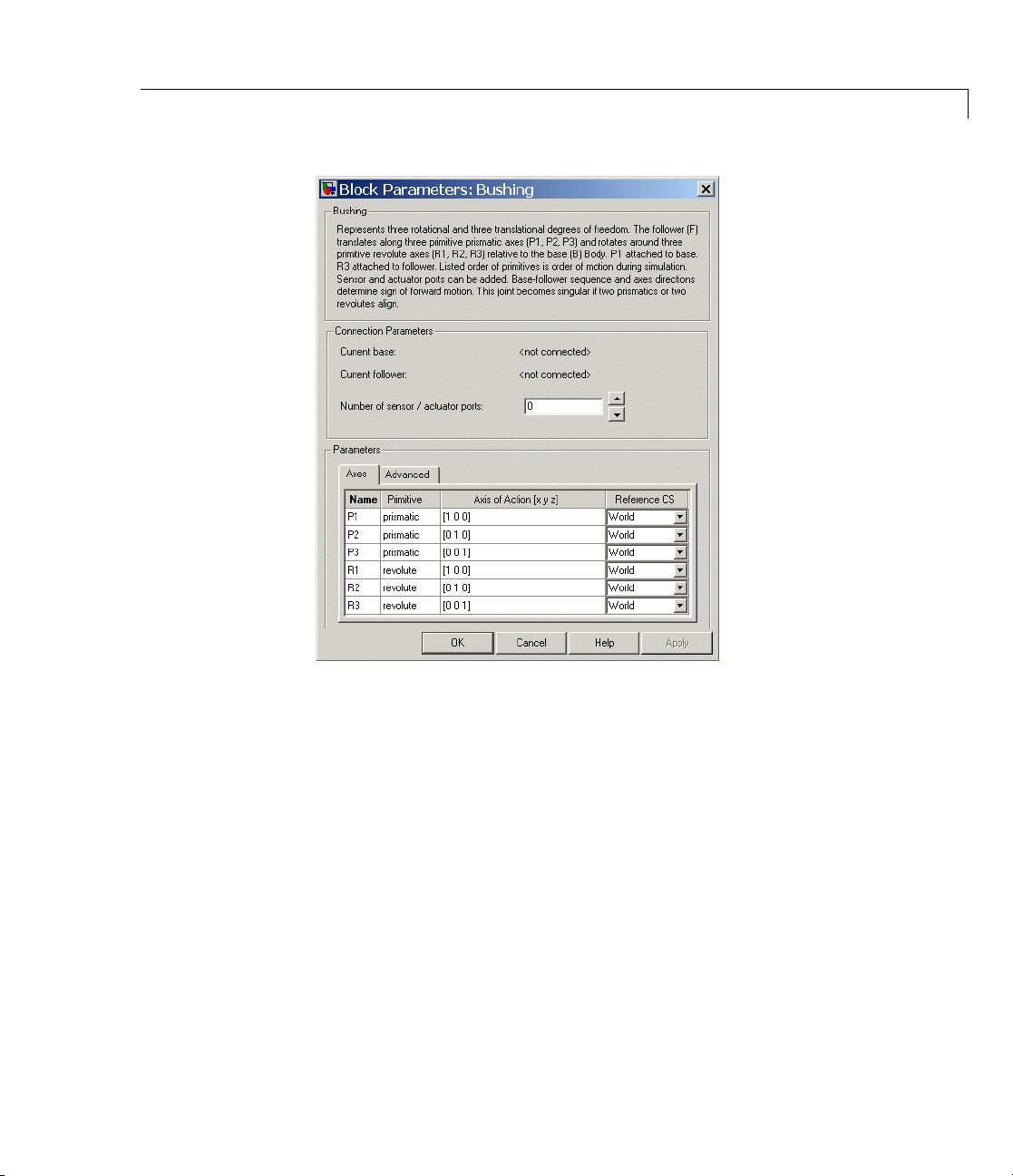
Bushing
Purpose Represent composite joint with three translational and three rotational
DoFs
Library Joints/Assembled Joints
Description The Bushing block represents a composite joint with three translational
degrees of freedom (DoFs) as three prismatic primitives and three
rotational D oFs as three revolute primitives. There are no constraints
among the primitives. Unlike Six-DoF, Bushing represents the
rotational DoFs as three revolutes, rather than as one spherical.
Warning
A joint with three revolute primitives becomes singular if two
or three of the rotation axes becomeparallel(“gimballock”). A
joint with two or three prismatic primitives becomes singular
if two or three of the translation axes become parallel. The
simulation stops with errors in these cases.
A joint with three revolute primitives must be configured in the
initial state with the three revolute primitive axes mutually
orthogonal. There are no restrictions on the primitive axes once
the simulation starts, except to prevent any two of the primitive
axes from becoming parallel.
Satisfying Joint Requirements
A Joint block represents the relative degrees of freedom between two
bodies, not the bodies themselves.
You must connect any Joint block to two and only two Body blocks, the
base and the follower. All Joints have tw o connector ports for these
connections, defining the direction of joint motion (base to follower).
You connect each side of the Joint block to these Body blocks at a Body
coordinate system (CS) port.
You specify the joint primitive axes, if any, in the Joint d i alog.
2-43

Bushing
Assembly Restrictions on Assembled Joints
This Joint block is assembled and places restrictions on the connected
Body CSs.
• If the Joint has no pri smatic primitives, the origins of the connected
Body CSs on either side of the Joint must be spatially collocated
points, to within assembly tolerances.
• If the Joint has one or more prismatic primitives, the origins of the
connected Body CSs must lie in the span of the prismatic axes:
Number of Prismatic
Primitives
One Along the prim itive axis
Two
Three
Span of Primitive Ax es
Intheplaneoftheprimitiveaxes
Anywhere in three-dimensional space
2-44
Dialog
Box a nd
Parameters
Bushing
Connection
Parameters
The dial
Paramet
The base (B)-follower (F) Body sequence determines the sense of positive
motion. Positive translation is the follower moving in the direction of
the translation axis. Positive rotation is the follower moving around the
rotational axis following the right-hand rule.
Current base
og has two active areas, Connection parameters and
ers.
When you connect the base (B) connector port on the Bushing
block to a Body CS Port on a Body, this param eter is automatically
reset to the name of this Body CS. See the following figure,
Bushing B ase and Follower Body Connector Ports on page 2-46.
2-45

Bushing
The base Body is automatically connected to the first joint
primitive
Current follower
When you connect the follower (F) connector port on the Bushing
block to a Body CS Port on a Body, this param eter is automatically
reset to the name of this Body CS. See the following figure,
Bushing B ase and Follower Body Connector Ports on page 2-46.
The follower B ody is automatically connected to the last joint
primitive
Number of sensor/actuator ports
Using this spinner menu, you can set the number of extra
connector ports needed for connecting Joint Actuator and Joint
Sensor blocks to this Joint. The default is
The motions of prismatic and revolute primitives are specified in
linear and angular units, respectively.
P1 in the primitive li st in Parameters.
R3 in the primitive li st in Parameters.
0.
Bushing Base and Follower Body Connecto r Por ts
Parameters Switch between the Axes and Advanced tabs.
Axes Tab
ntries on the Axes tab are required. Each DoF primitive in
The e
ing has an entry line. These lines specify the direction of the axes
Bush
tion of the DoFs that the Bushing represents.
of ac
2-46

Name - Primitive
The primitive list states the names and types of joint primitives
that make up the Bushing block: prismatic primitives
and revolute primitives
Axis of Action [x y z]
Enter here as a three-component vector the directional axes
defining the allowed motions of these primitives and their
corresponding DoFs:
• Prismatic: axis of translation
• Revolute: axis of rotation
The d efault vectors are shown in the dialog above. The axis is a
directed vector whose overall sign matters.
To prevent singularities and simulation errors, no two of the
revolute axes and no two of the prismatic axes can be parallel.
Reference CS
Using the pull-down menu, choose the coordinate system (World,
thebaseBodyCS,orthefollowerBodyCS)whosecoordinateaxes
the vector axis of action is oriented with respect to. This CS also
determines the absolute meaning of forces/torques and motion
along/about the joint axis. The default is
R1, R2, R3.
World.
Bushing
P1, P2, P3,
Restricted Parameters
When your model is in Restricted editing mode, you cannot modify the
following parameters:
• The Axes (joint primitives) parameters table
2-47

Bushing
Advanced Tab
The Advance
SimMechan
diagram.
Mark as th
In a close
one and on
If you wa
cutting
is not se
d tab is optional. You use it to control the way
ics simulation interprets the topology of your schematic
e preferred cut joint
d loop, the simulation internally and automatically cuts
ly one joint.
nt this particular joint to be weighted preferentially for
during the simulation, select the check box. The default
lected.
See Also Bearing, Cylindrical, Gimbal, Prismatic, Revolute, Six-DoF
See “Modeling D egrees of Freedom” for more on representing DoFs
with Joints.
See “Verifying Model Topology” and “How SimMechanics Software
Works” for more on closed loops and cutting.
2-48

Constraint & Driver Sensor
Purpose Measure constraint force or torque between pair of constrained bodies
Library Sensors & Actuators
Description The Constraint & Driver Sensor block me asures the force/torque of
constraint (reaction force/torque) betwe en a pair of bodies. You connect
this block to the Constraint or Driver block connected between the two
Bodies. The output signal is the reaction force/torque.
The Constraint & Driver Sensor measures the reaction force/torque in
the refe rence coordinate system (CS) specified in the block dialog. The
Constraint or Driver block connects a base and a follower Body. You
choose in the dialog to measure the reaction force/torque on either the
base or the follower Body.
The input is the connector port connected to the Constraint or Driver
block you want to sense. The outport is a set of Simulink signals or one
bundled Simulink signal of the reaction force/torque vector(s).
Physical and Unphysical Reaction Forces Not all the components
of the output reaction force/torque signal are significant. Only those
components projected into the subspace of the degrees of freedom
constrained or driven by the connected Constraint or Driver block are
physical. Components orthogonal to the constrained or d riven degrees
of freedom are unphysical.
A body’s orientation rotation matrix R relates vector components
measured in the body CS and in the inertial World CS by [R]·v
The column vector v
the body CS. The column vector v
measured in the World CS.
lists the vector v ’s three compone nts measured in
b
lists the vector v’s three components
s
b
= vs.
2-49

Constraint & Driver Sensor
Dialog
Box a nd
Parameters
The dialog has one active area, Measurements.
Measurements Reactions measured on
Inthepull-downmenu,choosetomeasurethereaction
force/torque on the base (B) or follower (F) Body. The default is
Base.
2-50
With respect to CS
In the pull-down menu, choose the CS in which the reaction
force/torque or motion is interpreted. The default is
World).
(
In the
Absolute case, the force vectors have components measured
relative to the inertial World CS axes. In the
force vector signals are premultiplied by the inverse rotation
matrix R
Reaction torque
Select the check box if you want to measure the reaction torque.
The default is selected. The torque is a row vector in the Simulink
output signal.
-1
= RTfor the Body selected in Reactions measured on.
Local case, the same
Absolute

Constraint & Driver Sensor
In the pull-down menu, choose the units for the reaction torque.
The default is
Reaction force
Select the check box if you want to measure the reaction force.
The default is selected. The force is a row vector in the Simulink
output signal.
In the pull-down menu, choose the units for the reaction force.
The default is
Output selected parameters as one signal
Select this check box to convert the output signals into a single
bundled signal. The default is selected. If you clear it, the
Constraint & Driver Sensor block will grow as many Simulink
outports as there are active sign als selected, one port for each
selected signal.
If the check box is selected, the Simulink signal out has all the
active signals bundled into a single row vector, ordered in the
order shown in the dialog. The type of the signal components
depends on which measurements are active (selected).
N*m (newton-meters).
N (newtons).
The sensor outputs are ordered and labeled as follows.
Constraint & Driver Sensor Output
Signal
Reaction torque
Reaction force
Label
Tr
Fr
Example Here is a Constraint & Driver Sensor connected to a Gear Constraint,
which connects and constraints two Bodies:
2-51

Constraint & Driver Sensor
You must add a Sensor port (connector port) to the Constraint/Driver
block to connect the Constraint & D riv er Sensor to it. The base
(B)-follower (F) Body sequence on the two sides of the Joint determines
the sense of the Constraint & Driver Sensor data.
See Also Body Sensor, Driver Actuator, Joint Sensor, Mechanical Branching Bar
See “Body Mo tion in SimMechanics Representations” and “Sensing
Motions and Forces”.
In Simulink, see the Signal Routing Library and the Sinks Library.
2-52
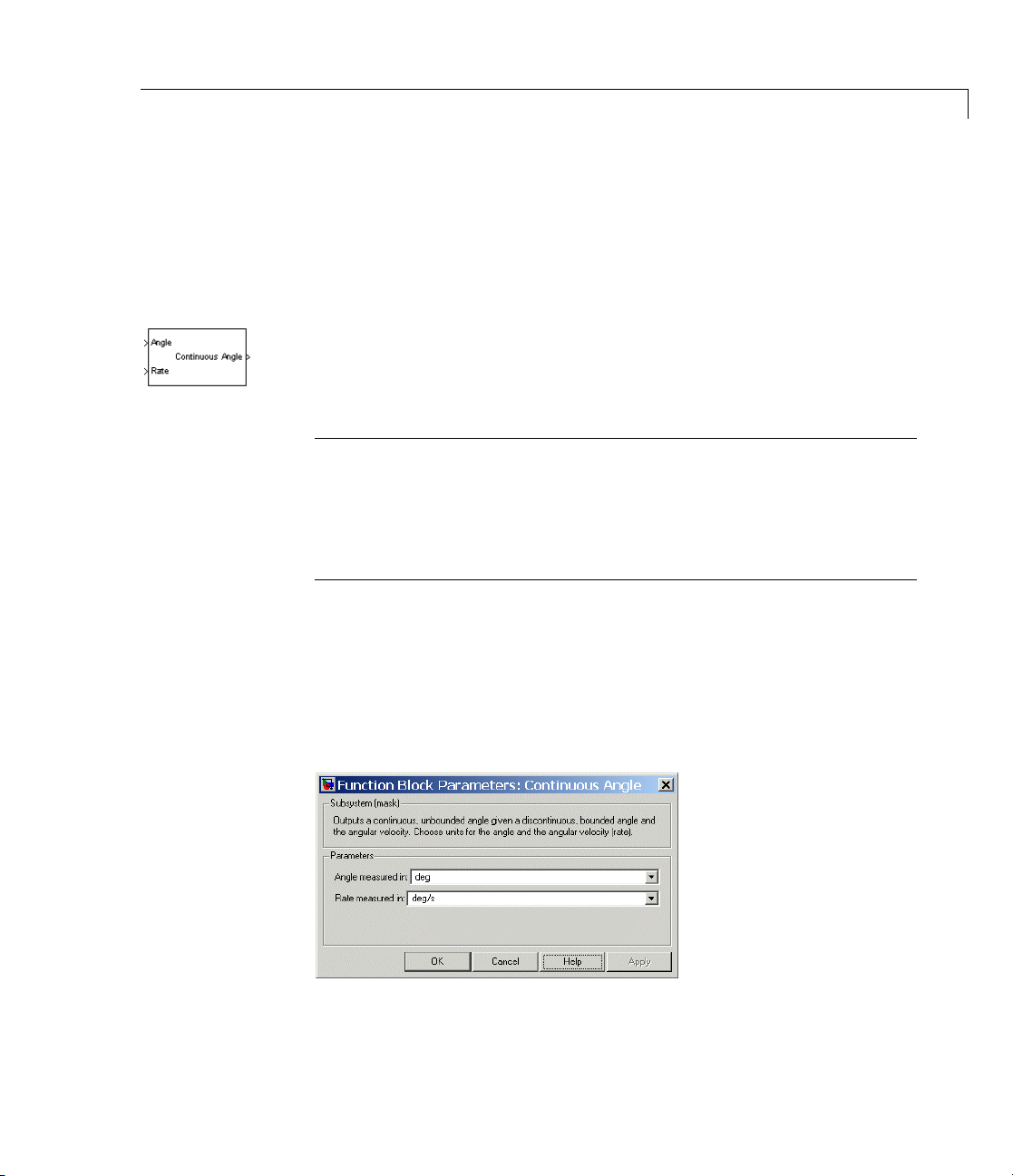
Continuous Angle
Purpose Convert discontinuous, bounded angular output from sensor to
continuous, unbounded angular output
Library Utilities
Description The Continuous Angle block converts a measured angle signal restricted
to the semiopen interval (-180
a continuous, unbounded angle not restricted to any interval. This
block requires the angle and the angular velocity as input signals. The
continuous, unbounded angle is the output signal.
Caution
Each Continuous Angle block in a model adds a normal Simulink
statetothemodel. Usethisblockwithcautionifyouaretrimming
or linearizing your model.
The Continuous Angle block does not any additional mechanical states.
The Joint Sensor block outputs the absolute rotational measurement of
revolute motion as a bounded angle in the interval (-180
or (-π,+π] radians. Motion that crosses the boundaries of this interval
causes discontinuities in the measured angle, from +180
vice versa. Use the Continuous Angle block if you want to convert this
restricted angular measurement to an unbo unded measurement.
o
,+180o] degrees or (-π,+π]radiansto
o
,+180o] degrees
o
to -180oor
Dialog
Box a nd
Parameters
2-53

Continuous Angle
Thedialoghasoneactivearea,Parameters.
Parameters Angle measured in
Choose the units for the input angle and the output continuous
angle, either
Rate measured in
Choose the units for the input rate (angular velocity), either
(degrees/second) or rad/s (radians/second). The default is deg/s
Example The tutorial “Modeling and Simulating a Closed-Loop Machine”
produces this angular motion output for the Revolute3 and Revolute
2joints:
deg (deg rees ) or rad (radians). The default is deg.
deg/s
2-54

Continuous Angle
The Revolute3 angle is restricted to the interval (-180o, +180o], so values
passing either limit of this interval are mapped to the opposite end of
the interval. The Revolute2 angle is not restricted, but instead touches
genuine turning points in its motion.
After passing the angles and angular velocities through Continuous
Angleblocks,theRevolute3angular motion a ppears different:
Revolute3’s motion is unchanged, but its angle is now continuous, w ith
no interval restriction. Revolute2’s angle is unchanged.
See Also Joint Sensor
See “Trimming Mechanical Models” and “Linearizing Mechanical
Models” for more about states.
2-55

Continuous Angle
See “Utilities” on page 1-7.
2-56

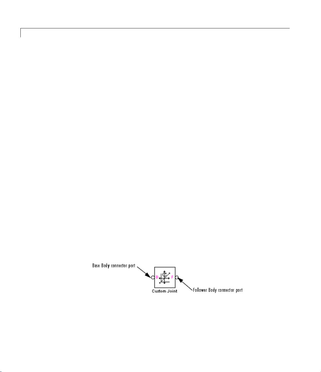
Custom Joint
Purpose Represent customizable composite joint with up to three translational
and up to three rotational degrees of freedom
Library Joints/Assembled Joints
Description The Custom Joint block is a composite joint that you can customize with
a specified combination of primitives (prismatic, revolute, or spherical)
representing the most general and unconstrained degrees of freedom
(DoFs) in three dimensions:
• Up to three translational DoFs as three prismatic primitives
• Up to three rotational DoFs:
- As a single spherical primitive
- As one, two, or three revolute primitives
The sense of rotational DoFs is defined by the right-hand rule. One
spherical or three revolutes together form a right-handed system.
You can add, configure, and delete these primitives from the Custom
Joint, w ith a minimum and default of one primitive. The properties of
eachprimitivearethesameastheindividualJointsofthesamenames.
Warning
A joint with two or three revolute primitives becomes singular
if two or three of the rotation axes become parallel (“gimbal
lock”). A joint with two or three prismatic primitives becomes
singular if two or three of the translation axes become parallel.
The simulation stops with errors in these cases.
A joint with three revolute primitives must be configured in the
initial state with the three revolute primitive axes mutually
orthogonal. There are no restrictions on the primitive axes once
the simulation starts, except to prevent any two of the primitive
axes from becoming parallel.
2-57

Custom Joint
You can connect Actuator and Sensor blocks to a Custom Joint, with
each Actuator and Sensor connecting to an individual primitive. You
cannot connect an Actuator to a spherical primitive.
Satisfying Joint Requirements
A Joint block represents the relative degrees of freedom between two
bodies, not the bodies themselves.
You must connect any Joint block to two and only two Body blocks, the
base and the follower. All Joints have tw o connector ports for these
connections, defining the direction of joint motion (base to follower).
You connect each side of the Joint block to these Body blocks at a Body
coordinate system (CS) port.
You specify the joint primitive axes, if any, in the Joint d i alog.
Assembly Restrictions on Assembled Joints
This Joint block is assembled and places restrictions on the connected
Body CSs.
• If the Joint has no pri smatic primitives, the origins of the connected
Body CSs on either side of the Joint must be spatially collocated
points, to within assembly tolerances.
2-58
• If the Joint has one or more prismatic primitives, the origins of the
connected Body CSs must lie in the span of the prismatic axes:
Number of Prismatic
Primitives
One Along the prim itive axis
Two
Three
Span of Primitive Ax es
Intheplaneoftheprimitiveaxes
Anywhere in three-dimensional space

Dialog
Box a nd
Parameters
Custom Joint
Connection
Parameters
The dialog has two active areas, Connection parameters and
Parameters.
The base (B)-follower (F) Body sequence determines the sense of
positive motion:
• Positive translation is the follower moving in the direction of the
translation axis.
• Positive rotation is the follower rotating in the right-hand rule about
the rotation axis.
• Positive rotation is the follower rotating in the right-hand rule as
shown by the motion figure in the Spherical block reference page.
2-59
Custom Joint
Current base
When you connect the base (B) connector port on the Custom
Joint block to a Body CS Port on a Body, this parameter is
automatically reset to the name of this Body CS. See the following
figure, Custom Joint Base and Follower Body Connector Ports
on page 2-60.
The base Body is automatically connected to the first joint
primitive in th e primitive list in Parameters.
Current follower
When you connect the follower (F) connector port on the Custom
Joint block to a Body CS Port on a Body, this parameter is
automatically reset to the name of this Body CS. See the following
figure, Custom Joint Base and Follower Body Connector Ports
on page 2-60.
The follower B ody is automatically connected to the last joint
primitive in th e primitive list in Parameters.
2-60
Number of sensor/actuator ports
Using this spinner menu, you can set the number of extra
connector ports needed for connecting Joint Actuator and Joint
Sensor blocks to this Joint. The default is
cannot be connected to an Actuator.
The motion o f a prismatic primitive is specified in linear units.
The motion of a revolute primitive is specified in angular units.
The motion of a spherical primitive is three DoFs specified in
quaternion form.
Custom Joint Base and Followe r Body Connector Ports
0. A spherical primitive
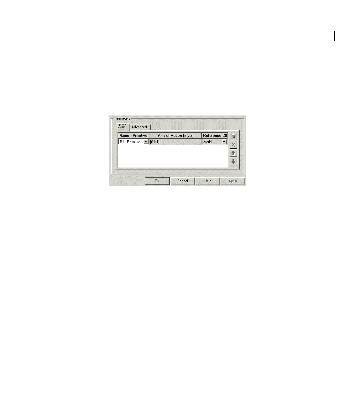
Parameters Switch between the Axes and Advanced tabs.
Axes Tab
The entries on the Axes tab are required. Each DoF primitive in
Custom Joint has an entry line. These lines specify the direction of the
axes of action of the DoFs that the Custom Joint represents.
Custom Joint
Name - Pri
In the pu
DoF. Up t
The rota
primiti
allowe
The def
Axis o
fAction[xyz]
Enter
defin
DoF:
• Pris
• Revo
• Sph
mitive
ll-down menu, select a label and primitive type for this
o three prismatic primitives
tional DoFs are represented by up to three revolute
ves:
R1, R2, R3. A spherical primitive S can take all three
d rotational DoFs instead.
ault value is
here as a three-component vector the directional axis
ing the allowe d motion of this primitive and its corresponding
matic: axis of translation
lute: axis of rotation
erical: field is not active
R1 - Revolute.
P1, P2, P3 are allowed.
2-61

Custom Joint
The default vector is [0 0 1]. The axis is a direc ted vector w h ose
overall sign matters.
To prevent singularities and simulation errors, no two of the
revolute axes and no two of the prismatic axes can be parallel.
Reference CS
Using the pull-down menu, choose the coordinate system (World,
thebaseBodyCS,orthefollowerBodyCS)whosecoordinateaxes
the vector axis of action is oriented with respect to. This CS also
determines the absolute meaning of forces/torques and motion
along/about the joint axis. The default is
The field is not active for a spherical primitive.
Managing the Joint Primitives List in a Custom Joint
The Custom Joint primitives list controls, in the figure, allow you to
add, reorder, and delete joint primitives in a Custom Joint block.
World.
2-62
Custom Joint Primitives List Controls
• To add a joint primitive to the primitives list:
- Highlight an existing primitive name in the list.

Custom Joint
- Click on the Add button (see the preceding figure, Custom Joint
Primitives List Controls on page 2-62).
A new primitive will appear immediately below the primitive you
highlighted.
• To change the position of a joint primitive in the list:
- Highlight t he primitive whose position you want to change.
- Click on the Up or Down button (see the preceding figure, Custom
Joint Primitives List Controls on page 2-62) until the primitive is
where you want it.
• To delete a joint primitive from the list:
- Highlig ht the primitive you want to delete.
- Click on the Delete button (see the preceding figure, Custom Joint
Primitives List Controls on page 2-62).
The primitive you highlighted disappears.
• Custom Joint requires at least one prim itiv e, which you cannot d ele t e.
Restricted Parameters
When your model is in Restricted editing mode, you cannot modify the
following parameters:
• The Axes (joint primitives) parameters table
2-63

Custom Joint
Advanced Tab
The Advance
SimMechan
diagram.
Mark as th
In a close
one and on
If you wa
cutting
is not se
d tab is optional. You use it to control the way
ics simulation interprets the topology of your schematic
e preferred cut joint
d loop, the simulation internally and automatically cuts
ly one joint.
nt this particular joint to be weighted preferentially for
during the simulation, select the check box. The default
lected.
See Also Bushing, Gimbal, Joint Actuator, Joint Initial Condition Actuator, Joint
Sensor, Joint Stiction Actuator, Prismatic, Revolute, Six-DoF, Spherical
See “Modeling D egrees of Freedom” for more on representing DoFs
with Joints.
See “Verifying Model Topology” and “How SimMechanics Software
Works” for more on closed loops and cutting.
2-64

Cylindrical
Purpose Represent composite joint with one translational DoF and one rotational
DoF, with parallel translation and rotation axes
Library Joints/Assembled Joints
Description The Cylindrical block represents a composite joint with one translational
degrees o f freedom (D oF) as one prismatic primitive and one rotational
DoF as one revolute primitive. The translation and rotation axes m ust
be parallel.
Satisfying Joint Requirements
A Joint block represents the relative degrees of freedom between two
bodies, not the bodies themselves.
You must connect any Joint block to two and only two Body blocks, the
base and the follower. All Joints have tw o connector ports for these
connections, defining the direction of joint motion (base to follower).
You connect each side of the Joint block to these Body blocks at a Body
coordinate system (CS) port.
You specify the joint primitive axes, if any, in the Joint d i alog.
Assembly Restrictions on Assembled Joints
This Joint block is assembled and places restrictions on the connected
Body CSs.
2-65

Cylindrical
• If the Joint has no pri smatic primitives, the origins of the connected
Body CSs on either side of the Joint must be spatially collocated
points, to within assembly tolerances.
• If the Joint has one or more prismatic primitives, the origins of the
connected Body CSs must lie in the span of the prismatic axes:
Dialog
Box a nd
Parameters
Number of Prismatic
Primitives
One Along the prim itive axis
Two
Three
Span of Primitive Ax es
Intheplaneoftheprimitiveaxes
Anywhere in three-dimensional space
2-66

Cylindrical
The dialog has two active areas, Connection parameters and
Parameters.
Connection
Parameters
The base (B)-follower (F) Body sequence determines the sense of positive
motion. Positive translation is the follower moving in the direction of
the translation axis. Positive rotation is the follower moving around the
rotational axis following the right-hand rule.
Current base
When you connect the base (B) connector port on the Cylindrical
block to a Body CS Port on a Body, this param eter is automatically
reset to the name of this Body CS. See the following figure,
Cylindrical Base and Follower Body Connector Ports on page 2-68.
The base Body is automatically connected to the first joint
primitive
Current follower
When you connect the follower (F) co nne cto r port on the
Cylindrical block to a Body CS Port on a Body, this parameter is
automatically reset to the name of this Body CS. See the following
figure, Cylindrical Base and Follower Body Connector Ports on
page 2-68.
The follower B ody is automatically connected to the last joint
primitive
Number of sensor/actuator ports
Using this spinner menu, you can set the number of extra
connector ports needed for connecting Joint Actuator and Joint
Sensor blocks to this Joint. The default is
P1 in the primitive li st in Parameters.
R1 in the primitive li st in Parameters.
0.
The motions of prismatic and revolute primitives are specified in
linear and angular units, respectively.
2-67
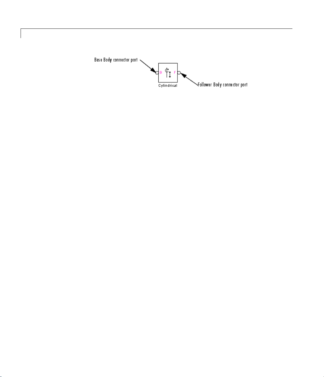
Cylindrical
Cylindrical Base and Follower Body Connector Ports
Parameters Switch between the Axes and Advanced tabs.
Axes Tab
The entries on the Axes tab are required. Each DoF primitive in
Cylindrical has an entry line. These lines specify the direction of the
axes o f action of the DoFs that the Cylindrical represents.
Name - Primitive
The primitive list states the names and types of joint primitives
that make up the Cylindrical block: prismatic revolute
revolute primitive
R1.
P1 and
2-68
Axis of Action [x y z]
Enter here as a three-component vector the directional axes
defining the allowed motions of these primitives and their
corresponding DoFs:
• Prismatic: axis of translation
• Revolute: axis of rotation
The default vectors are shown in the dialog above. The axes are
directed vectors whose overall sign matters.
The two axes
Reference CS
Using the pull-down menu, choose the coordinate system (World,
thebaseBodyCS,orthefollowerBodyCS)whosecoordinateaxes
the vector axis of action is oriented with respect to. This CS also
P1 and R1 in Cylindrical must be aligned.

Cylindrical
determines the absolute meaning of forces/torques and motion
along/about the joint axis. The default is
Restricted Parameters
When your model is in Restricted editing mode, you cannot modify the
following parameters:
• The Axes (joint primitives) parameters table
Advanced Tab
World.
See
Also
The Advanced tab is optional. You use it to control the way
SimMechanics simulation interprets the topology of your schematic
diagram.
Mark as the preferred cut joint
In a closed loop, the simulation internally and automatically cuts
one and only one joint.
If you want this particular joint to be weighted preferentially for
cutting during the simulation, select the check box. The default
is not selected.
assembled Cylindrical, Prismatic, Revolute, Screw
Dis
“Modeling Degrees of Freedom” for more on representing DoFs
See
hJoints.
wit
2-69

Cylindrical
See “Verifying Model Topology” and “How SimMechanics Software
Works” for more on closed loops and cutting.
2-70

Disassembled Cylindrical
Purpose Represent disassembled cylindrical joint, with one translational DoF
and one rotational DoF along and about misaligned axes, with no
constraints
Library Joints/Disassembled Joints
Description The Disassembled Cylindrical block represents a composite joint,
one translational and one rotational degrees of freedom (D oF ) along
and about a pair of specified misaligned axes between two bodies.
SimMechanics simulation automatically assembles (aligns) the two axes
at simulation start when it defines a machine’s assembled configuration.
A cylindrical joint is composite, with two DoFs and a single specified
axis: a prismatic primitive translating along the axis, and a revolute
primitive rotating about the axis. There are no constraints between
the two primitives.
Disassembled Cylindrical Axes of Follo wer (blue) and Base (red)
2-71
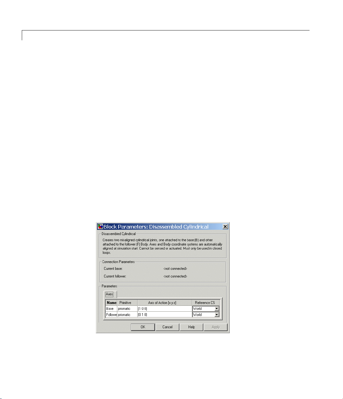
Disassembled Cylindrical
Satisfying Joint Requirements
A Joint block represents the relative degrees of freedom between two
bodies, not the bodies themselves.
You must connect any Joint block to two and only two Body blocks, the
base and the follower. All Joints have a default of two connector ports
for these connections, defining the direction of joint motion (base to
follower). You connect each side of the Joint block to these Body blocks
at a Body coordinate system (CS) point.
You specify the joint primitive axes, i f any, in the Joint dialog. The two
disassembled primitive joint axes are associated, in order, with the base
and follower Bodies, respectively.
You canno t connect an Actuator or Sensor to a D isasse mbled Joint.
Assembly Restrictions on Disassembled Joints
This Joint block is disassemb led: the connected Body CS origins do not
need to be spatially collocated points or lie within the span of prismatic
primitives, if any.
Dialog
Box a nd
Parameters
2-72
You can only use a Disassembled Joint block within a closed loop. One
loop can have no more than one disassembled joint.
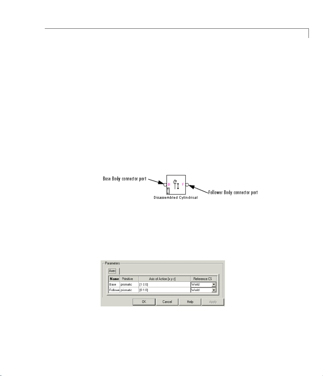
Disassembled Cylindrical
The dialog has two active areas, Connection parameters and
Parameters.
Connection
Parameters
Current base
When you connect the base (B) connector port on the Disassembled
Cylindrical block to a Body CS Port on a Body, this parameter
is automatically reset to thenameofthisBodyCS.Seethe
following figure, Disassembled Cylindrical Base and Follower
Body Connector Ports on page 2-73.
Current follower
When you connect the follower (F) co nne cto r port on the
Disassembled Cylindrical block to a Body CS Port on a Body, this
parameter is automatically reset to the name of this Body CS. See
the following figure, Disassembled Cylindrical Base and Follower
Body Connector Ports on page 2-73.
Disasse
mbled Cylindrical Base and Follower Body Connecto r Ports
Parameters There is one Axes tab.
The entries on the Axes tab are required. They specify the directions of
the two misaligned axes of the translational-rotational DoFs that the
Disassembled Cylindrical represents.
2-73

Disassembled Cylindrical
Name
This column automatically displays the names of the two
misaligned rotation axes attached to base and follower bodies,
respectively.
Axis of Action [x y z]
Enter here as two three-component vectors the two misaligned
directional axes along and about which the base and follower
bodies respectively can translate and rotate. The default vectors
are
[1 0 0] and [0 1 0], respectively. The axes are directed
vectors whose overall signs matter.
Reference CS
Using t he pull-down menu, choose thecoordinatesystems(World,
the base Body CS, or the follower Body CS) whose coordinate
axes the two vector axes of translation-rotation are oriented with
respect to. The defaults are
Restricted Parameters
When your model is in Restricted editing mode, you cannot modify the
following parameters:
World.
• The Axes (joint primitives) parameters table
See Also Cylindrical, Disassembled Prismatic, Disassembled Revolute,
Disassembled Spherical
See “Modeling D egrees of Freedom” for more on representing DoFs
with Disassembled Joints.
See “Verifying Model Topology” and “How SimMechanics Software
Works” for more on closed loops and cutting disassembled joints.
2-74
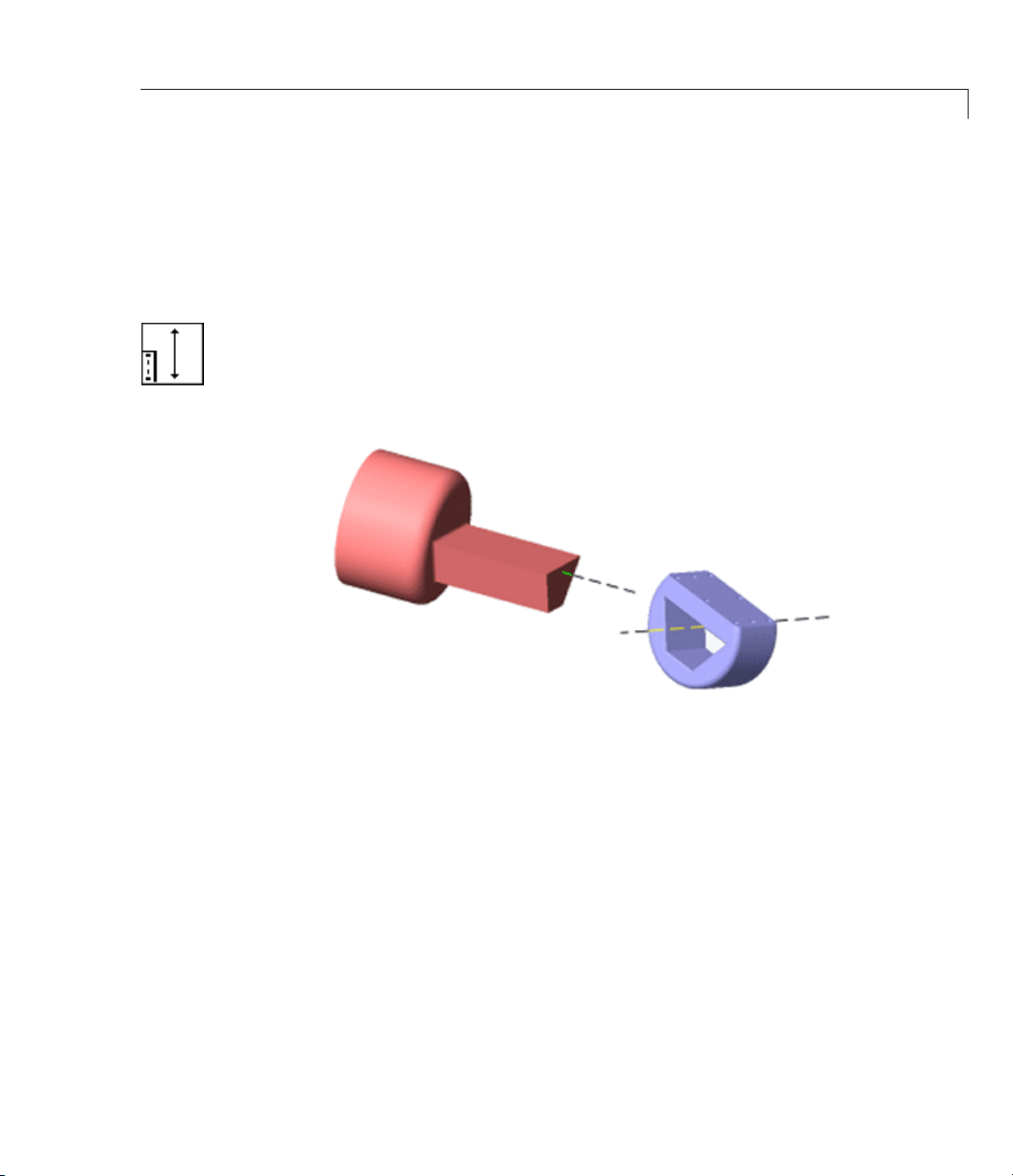
Disassembled Prismatic
Purpose Represent disassembled prismatic joint with one tran sl ati onal degree
of freedom alon g misaligned axes
Library Joints/Disassembled Joints
Description The Disassembled Prismatic block r epresents a single translational
degrees of freedom (D oF) along a pair of specified misaligned axes
between two bodies. SimMechanics simulation automatically assem bles
(aligns) the translation axes at simulationstartwhenitdefinesa
machine’s assembled configuration.
Disassembled Prismatic Axes of Follower (blue) and Base (red)
2-75
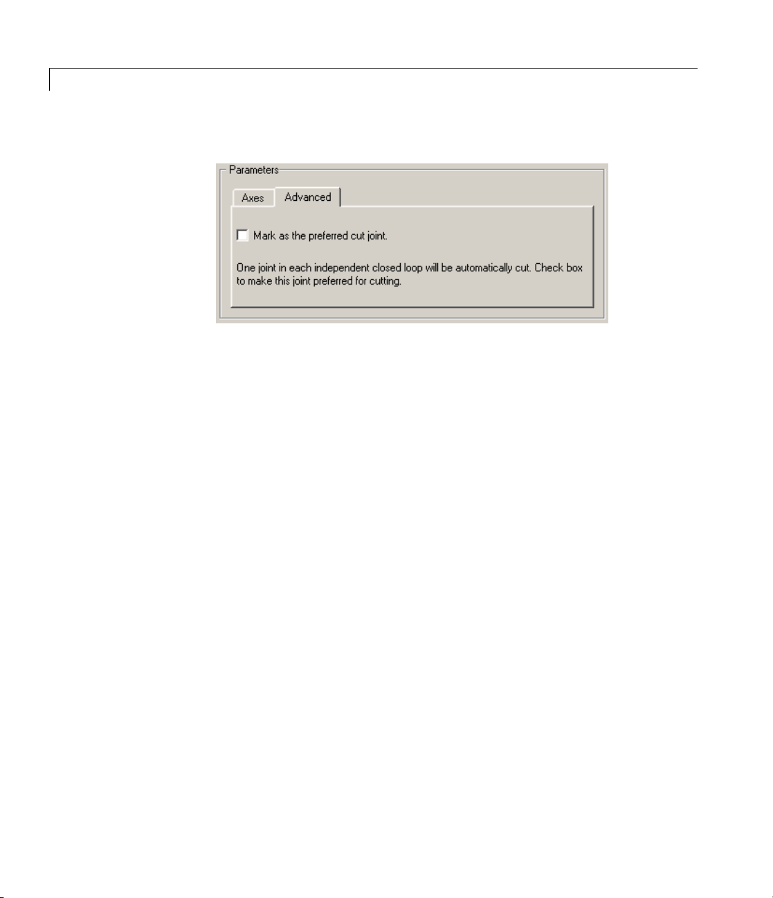
Disassembled Prismatic
Advanced Tab
The Advance
SimMechan
diagram.
Mark as th
ics simulation interprets the topology of your schematic
e preferred cut joint
In a close
one and on
If you wa
cutting
is not se
d tab is optional. You use it to control the way
d loop, the simulation internally and automatically cuts
ly one joint.
nt this particular joint to be weighted preferentially for
during the simulation, select the check box. The default
lected.
2-76

Dialog
Box a nd
Parameters
Disassembled Prismatic
The dialog has two active areas, Connection parameters and
Parameters.
Connection
Parameters
Current base
When you connect the base (B) connector port on the Disassembled
Prismatic block to a Body CS Port on a Body, this parameter
is automatically reset to thenameofthisBodyCS.Seethe
following figure, Disassembled Prismatic Base and Follower Body
Connector Ports on page 2-78.
Current follower
When you connect the follower (F) co nne cto r port on the
Disassembled Prismatic block to a Body CS Port on a Body, this
parameter is automatically reset to the name of this Body CS. See
the following figure, Disassembled Prismatic Base and Follower
Body Connector Ports on page 2-78.
2-77

Disassembled Prismatic
Disassembled Prismatic Base and Follower Body Connector Ports
Parameters There is one Axes tab.
The entries on the Axes tab are required. They specify the directions of
the two misaligned axes of the translational D oF that the Disassembled
Prismatic represents.
2-78
Name
This column automatically displays the names of the two
misaligned translation axes attached to base and follower bodies,
respectively.
Axis of translation [x y z]
Enter here as two three-component vectors the two misaligned
directional axes along which the base and follower bodies
respectively can translate. The default vectors are
[0 1 0], respectively. The axes are directed vectors whose overall
signs matter.
Reference CS
Using t he pull-down menu, choose thecoordinatesystems(World,
thebaseBodyCS,orthefollowerBodyCS)whosecoordinateaxes
the two vector axes of translation are oriented with respect to.
The defaults are
World.
[1 0 0] and

Disassembled Prismatic
Restricted Parameters
When your model is in Restricted editing mode, you cannot modify the
following parameters:
• The Axes (joint primitives) parameters table
See Also Disassembled Cylindrical, Disassembled Revolute, Disassembled
Spherical, Prismatic
See “Modeling D egrees of Freedom” for more on representing DoFs
with Disassembled Joints.
See “Verifying Model Topology” and “How SimMechanics Software
Works” for more on clo sing loops with disassembled joints.
2-79

Disassembled Revolute
Purpose Represent disassembled revolute joint with one rotational degree of
freedom about misaligned axes
Library Joints/Disassembled Joints
Description The Disassembled Revolute block represents a single rotational degrees
of freedom (DoF) along a pair of specified misaligned axes between two
bodies. SimMechanics simulation automatically assembles (aligns) the
rotation axes at simulation start when it defines a machine’s assembled
configuration.
2-80
Disassembled Revolute Axes of Follower (blue) and Base (red)
Satisfying Joint Requirements
A Joint block represents the relative degrees of freedom between two
bodies, not the bodies themselves.
You must connect any Joint block to two and only two Body blocks, the
base and the follower. All Joints have a default of two connector ports

Dialog
Box a nd
Parameters
Disassembled Revolute
for these connections, defining the direction of joint motion (base to
follower). You connect each side of the Joint block to these Body blocks
at a Body coordinate system (CS) point.
You specify the joint primitive axes, i f any, in the Joint dialog. The two
disassembled primitive joint axes are associated, in order, with the base
and follower Bodies, respectively.
You canno t connect an Actuator or Sensor to a D isasse mbled Joint.
Assembly Restrictions on Disassembled Joints
This Joint block is disassemb led: the connected Body CS origins do not
need to be spatially collocated points or lie within the span of prismatic
primitives, if any.
You can only use a Disassembled Joint block within a closed loop. One
loop can have no more than one disassembled joint.
The dialog has two active areas, Connection parameters and
Parameters.
2-81

Disassembled Revolute
Connection
Parameters
Current base
When you connect the base (B) connector port on the Disassembled
Revolute block to a Body CS Port on a Body, this parameter is
automatically reset to the name of this Body CS. See the following
figure, Disasse mbled Revolute Base and Follow er Body Conne cto r
Ports on page 2-82.
Current follower
When you connect the follower (F) co nne cto r port on the
Disassembled Revolute block to a Body CS Port on a Body, this
parameter is automatically reset to the name of this Body CS. See
the following fig ure, Disassembled Revolute Base and Follower
Body Connector Ports on page 2-82.
Disassembled Revolute Ba se and Follower Body Connector Por ts
Parameters There is one Axes tab.
The entries on the Axes tab are required. They specify the directions of
the two misaligned axes of the rotational DoF that the Disassembled
Revolute represents.
2-82

Disassembled Revolute
Name
This column automatically displays the names of the two
misaligned rotation axes attached to base and follower bodies,
respectively.
Axis of rotation [x y z]
Enter here as two three-component vectors the two misaligned
directional axes about which the base and follower bodies
respectively can rotate. The default vectors are
, respectively. The axes are directed vectors whose overall
10]
signs matter.
Reference CS
Using t he pull-down menu, choose thecoordinatesystems(World,
thebaseBodyCS,orthefollowerBodyCS)whosecoordinateaxes
the two vector axes of rotation are oriented with respect to. The
defaults are
Restricted Parameters
When your model is in Restricted editing mode, you cannot modify the
following parameters:
World.
[1 0 0] and [0
• The Axes (joint primitives) parameters table
See Also Disassembled Cylindrical, Disassembled Prismatic, Disassembled
Spherical, Revolute
See “Modeling D egrees of Freedom” for more on representing DoFs
with Disassembled Joints.
See “Verifying Model Topology” and “How SimMechanics Software
Works” for more on clo sing loops with disassembled joints.
2-83
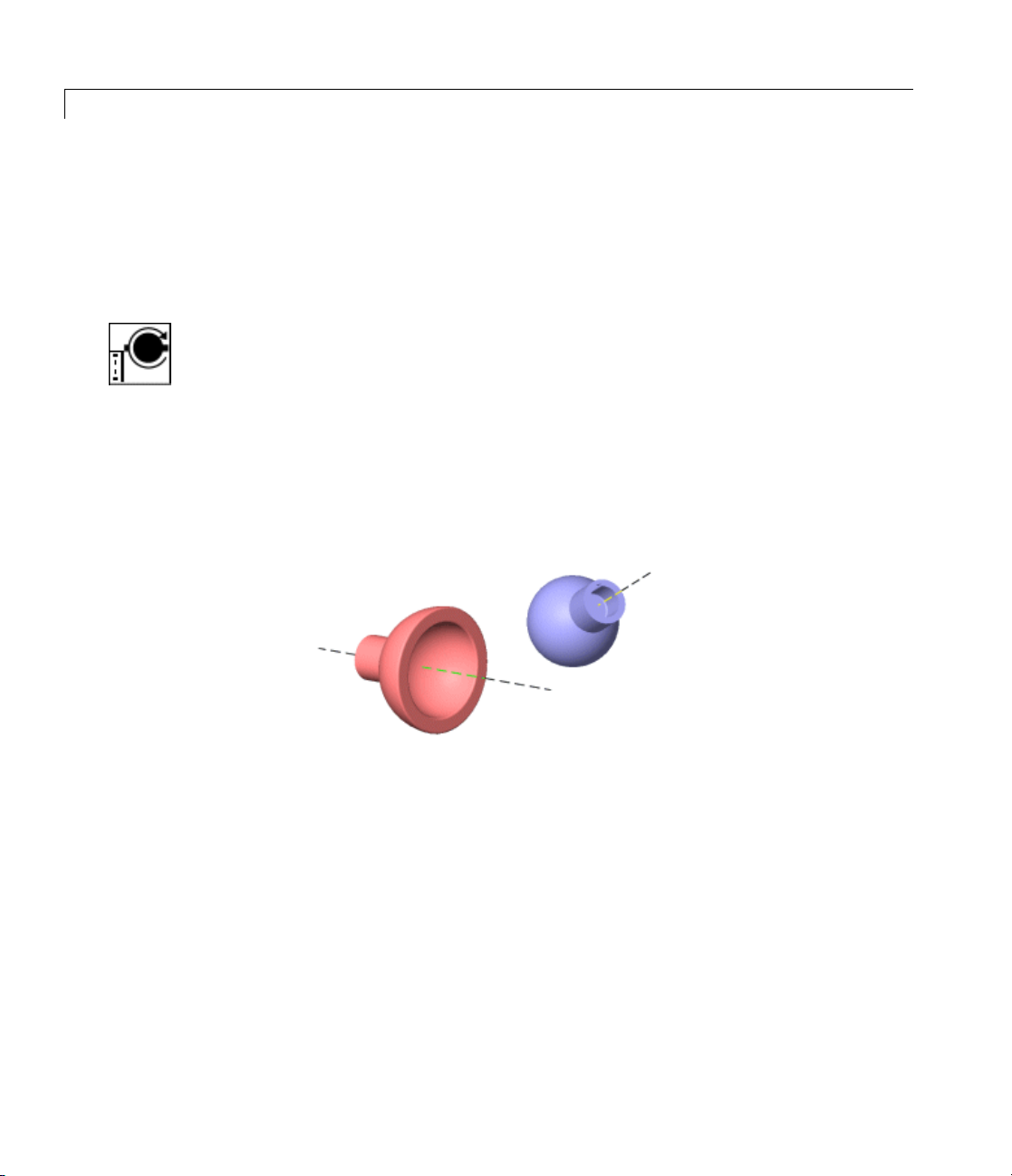
Disassembled Spherical
Purpose Represent d isas semble d spherical joint with three rotational degrees of
freedom about dislocated pivots
Library Joints/Disassembled Joints
Description The Disassembled Spherical block represents three rotational degrees
of freedom (DoF) about a pair of specified dislocated pivots at the two
bodies, separated “ball-in-socket” joints. SimMechanics simulation
automatically assembles (collocates) the spherical pivots at simulation
start when it defines a machine’s assembled configuration.
Two rotational DoFs specify a directional axis, and a third rotational
DoF specifies rotation about that directional axis. (See the motion figure
in the Spherical block reference page.) The sense of each rotational
DoF is defined by the right-hand rule. Unlike the Gimbal block, the
Disassembled Spherical block cannot become singular.
2-84
Disassembled Spherical Pivots of Follower (blue) and Base (red)
Satisfying Joint Requirements
A Joint block represents the relative degrees of freedom between two
bodies, not the bodies themselves.
You must connect any Joint block to two and only two Body blocks, the
base and the follower. All Joints have a default of two connector ports
for these connections, defining the direction of joint motion (base to
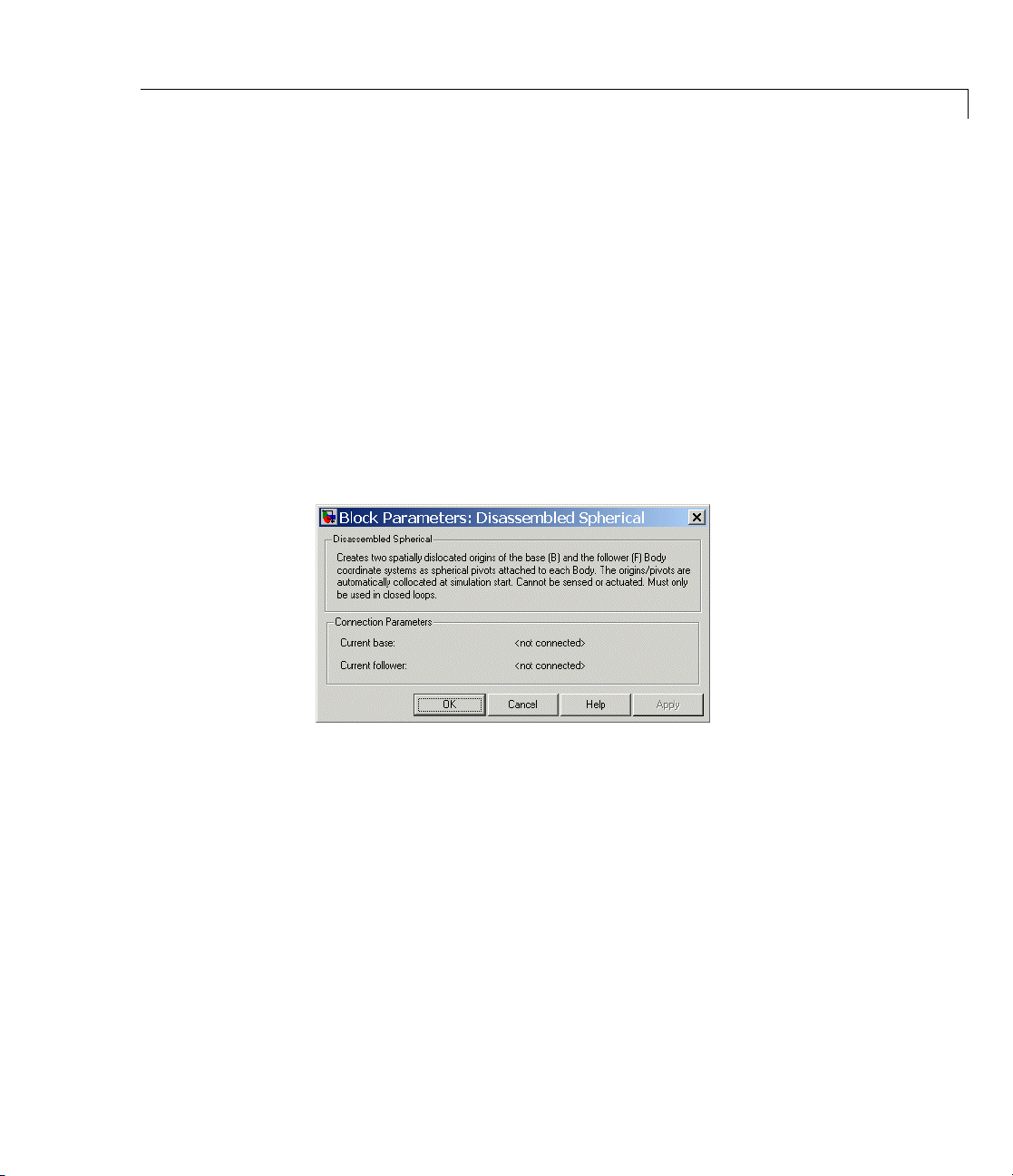
Dialog
Box a nd
Parameters
Disassembled Spherical
follower). You connect each side of the Joint block to these Body blocks
at a Body coordinate system (CS) point.
You specify the joint primitive axes, i f any, in the Joint dialog. The two
disassembled primitive joint axes are associated, in order, with the base
and follower Bodies, respectively.
You canno t connect an Actuator or Sensor to a D isasse mbled Joint.
Assembly Restrictions on Disassembled Joints
This Joint block is disassemb led: the connected Body CS origins do not
need to be spatially collocated points or lie within the span of prismatic
primitives, if any.
You can only use a Disassembled Joint block within a closed loop. One
loop can have no more than one disassembled joint.
Connection
Parameters
The dialog has one area, Connection parameters,whichisinactive.
Current base
When you connect the base (B) connector port on the Disassembled
Spherical block to a Body CS Port on a Body, this parameter
is automatically reset to thenameofthisBodyCS.Seethe
following figure, Disassembled Spherical Base and Follower Body
Connector Ports on page 2-86.
2-85

Disassembled Spherical
Current follower
When you connect the base (F) connector port on the Disassembled
Spherical block to a Body CS Port on a Body, this parameter
is automatically reset to thenameofthisBodyCS.Seethe
following figure, Disassembled Spherical Base and Follower Body
Connector Ports on page 2-86.
Disassembled Spherical Base and Follower Body Connector Ports
See Also Disassembled Cylindrical, Disassembled Prismatic, Disassembled
Revolute, Gimbal, Spherical
See “Modeling D egrees of Freedom” for more on representing DoFs
with Disassembled Joints.
2-86
See “Verifying Model Topology” and “How SimMechanics Software
Works” for more on clo sing loops with disassembled joints.

Distance Driver
Purpose Specify distance between two Body CS origins as function of time
Library Constraints & Drivers
Description The Distance Driver block drives thedistancebetweentheoriginsof
two Body coordinate system (CS) as a function of time that you specify.
This function must always remain nonnegative during the simulation.
Let r
, r2be the vector positions of the origins of CS1 on one Body and
1
CS2 on the other Body, respectively. These vectors can be measured in
anyCS.TheDistanceDriverspecifiesthescalardistanced =|r
between these points as a function of time:
1
- r2|
||()()rr
12
You connect the D istance Driver to a Driver Actuator block.
The Simulink input signal into the Driver Actuator specifies the
time-dependent driving function f(t) and its first two derivatives, as well
as their units. If you do not actuate Distance Driver, this block acts as a
time-independent constraint that freezes the distance between the two
Body CSs at its initial value d(t=0) during the simulation.
Caution
The block computes the initial distance d(t=0) between the coordinate
systems when the machine is in its home configuration, the original
configuration of the machine’s bodie s before the simulation imposes
initial conditions and implements joint assembly.
See “Kinematics and the Machine’s State of Motion” and “How
SimMechanics Software Works”.
Drivers restrict relative degrees of free dom (DoFs) between a pair of
bodies as specified functions of time. Locally in a machine, they replace
a Joint as the expression of the DoFs. Globally, Driver blocks must
occur topologically in closed loops. Like Bodies connected to a Joint, the
0 − ==+dt f t
2-87

Distance Driver
Dialog
Box a nd
Parameters
two Bodies connected to a Drivers are ordered as base and follower,
fixing the direction of relative motion.
You can also connect a Constraint & Driver Sensor to any Driver and
measure the reaction forces /torques between the driven bodies.
Thedialoghasoneactivearea,Connection parameters.
Connecti
Parameters
2-88
on
The base (
motion.
the tran
Curren
Curre
slation axis.
tbase
When yo
Driver
automa
figur
on pag
nt follower
When
Driv
auto
figu
on p
B)-follower (F) Body sequence determines the sense of positive
Positive translation is the follower moving in the direction of
u connect the base (B) connector port on the Distance
block to a Body CS Port on a Body, this parameter is
tically reset to the name of this Body CS. See the following
e, Distance Driver Base and Follower Body Connector Ports
e2-89.
you connect the follower (F) connector port on the Distance
er block to a Body CS Port on a Body, this parameter is
matically reset to the name of this Body CS. See the following
re, D istance Driver Base and Follower Body Connector Ports
age 2-89.
 Loading...