


SimMechanics™ 3
Visualization and Import Guide
How to Contact The MathWorks
www.mathworks.
comp.soft-sys.matlab Newsgroup
www.mathworks.com/contact_TS.html Technical Support
suggest@mathworks.com Product enhancement suggestions
bugs@mathwo
doc@mathworks.com Documentation error reports
service@mathworks.com Order status, license renewals, passcodes
info@mathwo
com
rks.com
rks.com
Web
Bug reports
Sales, prici
ng, and general information
508-647-7000 (Phone)
508-647-7001 (Fax)
The MathWorks, Inc.
3 Apple Hill Drive
Natick, MA 01760-2098
For contact information about worldwide offices, see the MathWorks Web site.
SimMechanics™ Visualization and Import Guide
© COPYRIGHT 2001–2010 by The MathWorks, Inc.
The software described in this document is furnished under a license agreemen t. The software may be used
or copied only under the terms of the license agreement. No part of this manual may be photocopied or
reproduced in any form without prior written consent from The MathW orks, Inc.
FEDERAL ACQUISITION: This provision applies to all acquisitions of the Program and Documentation
by, for, or through the federal government of the United States. By accepting delivery of the Program
or Documentation, the government hereby agrees that this software or documentation qualifies as
commercial computer software or commercial computer software documentation as such terms are used
or defined in FAR 12.212, DFARS Part 227.72, and DFARS 252.227-7014. Accordingly, the term s and
conditions of this Agreement and only those rights specified in this Agreement, shall pertain to and govern
theuse,modification,reproduction,release,performance,display,anddisclosureoftheProgramand
Documentation by the federal government (or other entity acquiring for or through the federal government)
and shall supersede any conflicting contractual terms or conditions. If this License fails to meet the
government’s needs or is inconsistent in any respect with federal procurement law, the government agrees
to return the Program and Docu mentation, unused, to The MathWorks, Inc.
Trademarks
MATLAB and Simulink are registered trademarks of The MathWorks, Inc. See
www.mathworks.com/trademarks for a list of additional trademarks. Other product or brand
names may be trademarks or registered trademarks of their respective holders.
Patents
The MathWorks products are protected by one or more U.S. patents. Please see
www.mathworks.com/patents for more information.
Revision History
October 2008 Online only New for Version 3.0 (Release 2008b)
March 2009 Online only Revised for Version 3.1 (Release 2009a)
September 2009 Online only Revised for Version 3.1.1 (Release 2009b)
March 2010 Online only Revised for Version 3.2 (Release 2010a)

Introducing Visualization and Animation
1
About SimM echanics Visualization .................. 1-2
Starting SimMechanics Visualization
Using SimMechanics Visualization
About Body Color and Geometry: Default, Standard,
and Custom
About Body Color: Default and Custom
About Body Geometry: Default, Standard, and Custom
Standard Body Geometry: Equivalent Ellipsoids
Standard Body Geometry: Convex Hulls
Custom B ody Geometry and External Graphics Files
Hierarchy of Body, Machine, and Model Visualization
Settings
Visualized Geometries and Colors from Body Block
Settings
Body Block Settings Affecting Body Visualization
Visualization Settings in the Machine and Model
Hierarchy
..................................... 1-5
........................................ 1-11
....................................... 1-11
...................................... 1-13
................. 1-2
................... 1-3
............... 1-5
........ 1-5
............... 1-9
....... 1-12
Contents
.. 1-5
.... 1-10
Getting Started with the Visualization Window
2
Introducing the SimMechanics Visualization
Window
About the Visualization Window
Opening and Updating the Visualization Window
Visualization Toolbar and Its Controls
Controlling Body and Body Component Display
About Body and Body Component Display
......................................... 2-2
..................... 2-2
....... 2-2
................ 2-4
...... 2-6
............. 2-6
iii

Interpreting the Body Display Symbols and Shapes ..... 2-6
Changing Body Display Symbols
Changing Body Display Shapes
..................... 2-7
...................... 2-7
Adjusting the Camera View
Setting the Background Color
Interpreting the Camera Pro j ection, Field of View, and
Viewpoint
Automatically Sizing the Camera Field of View
Automatically Setting a Camera Viewpoint
Actively Controlling the Camera View point
Camera Viewpoint and Mouse Controls
Communicating with the Model from the Visualization
Window
Highlighting Bodies, B ody Components, and Body
Blocks
Updating the Model Diagram
Saving Visualization Settings to the Model
Controlling and Timing Simulation from the
Visualization Window
Starting, Pausing, and Stopping the Simulation
Timing the Simulation
Controlling Animation
About Animation
How Animation Works
Automatically Adapting the Camera View to the D isplayed
Motion
Changing How the Animation Is Updated
Speeding Up the Animation in Real Time
...................................... 2-9
......................................... 2-17
........................................ 2-17
.................................. 2-23
........................................ 2-24
......................... 2-9
....................... 2-9
......... 2-11
............ 2-12
............ 2-13
............... 2-14
........................ 2-18
............. 2-19
............................ 2-21
........ 2-21
............................. 2-21
............................. 2-23
............................. 2-23
............. 2-25
.............. 2-27
iv Contents
Recording Animation
About Recording
How Recording Works
Recording Animations
Compressing Anim ation Recordings
Controlling the Size of the Recorded Animation
Playing Recordings of Animation
.............................. 2-28
.................................. 2-28
.............................. 2-28
.............................. 2-28
.................. 2-30
..................... 2-31
......... 2-31

Visualization Menus and Their Controls ............. 2-33
About the SimMechanics Visualization Window Menus
View Menu
Simulation Menu
Model Menu
Help Menu
....................................... 2-34
.................................. 2-35
...................................... 2-38
....................................... 2-39
Customizing Visualization and Animation
3
About Custom SimMechanics Visualization .......... 3-2
Customizing Visualization Settings
Creating an External Virtual Reality Client
................... 3-2
............ 3-3
.. 2-33
Customizing Visualized Body Colors
Choosing Custom Body Colors
Switching Between Default and Custom Body Colors
Customizing Visualized Body Geometries
Choosing Custom Body Geometries
Switching Between Standard Body Geometries
About STL Body Graphics Files
Obtaining STL Body Graphics Files for Custom Body
Geometries
Switching Between Standard and Custom Body
Geometries
Visualizing with a Virtual Reality Client
About Virtual Worlds for Machines and Models
Creating Virtual Worlds for SimMechanics Models
Interfacing SimMechanics Models with Virtual Worlds
Reference
.................................... 3-9
.................................... 3-10
........................................ 3-27
....................... 3-4
...................... 3-8
................ 3-4
............ 3-7
................... 3-7
............. 3-13
.... 3-4
......... 3-7
......... 3-13
...... 3-13
... 3-18
v

Importing Mechanical Models
4
Introducing M echanical Import ..................... 4-2
About Mechanical Import and CAD Translation
Requirements for CAD Export and Mechanical Import
Essential CAD Translation Steps
Generating New Models from Physical Modeling
XML
About Generated SimMechanics Models Based on CAD
Generating a New Model from a Physical Modeling XML
Controlling New Model Import with Nondefault Options
............................................ 4-6
File
........................................... 4-7
.................... 4-4
........ 4-2
... 4-3
.. 4-6
.. 4-8
Working with Generated Models
About CAD-Based Models
Common Features of CAD-Based Models
Nondefault Features in Generated Models
Manually Modifying and Extending Generated Models
After Import
Updating Generated Models Using Physical Modeling
XML
About Model Update and Mechanical Import
Updating a Machine in a Generated Model with
Adding a New Machine to a Generated Model
Replacing Generated Model or Subsystem Contents with a
Controlling Model Update at the Block Level
About Associativity and Updating
Working with Associativity in Common Updating
Controlling How Update-Import Changes Individual Blocks
Associativity in an Updating Sequence Example
............................................ 4-22
Revisions
New Machine
Situations
and Connections
................................... 4-17
...................................... 4-25
................................... 4-29
..................................... 4-35
........................... 4-12
................................ 4-38
.................... 4-12
.............. 4-12
............. 4-15
........... 4-22
.......... 4-28
......... 4-32
.................... 4-32
........ 4-42
vi Contents
Troubleshooting Imported and Updated Models
Best Practices for Creating and Exporting Assemblies
...... 4-46
... 4-46

Inserting Reference Coordinate Systems into Assemblies
Before Export
Controlling Mechanical Import to Assist
Troubleshooting
Troubleshooting Erro rs During Model Generation
Troubleshooting Errors During Model Update
Troubleshooting M ode l Simulation Errors
Troubleshooting SimMechanics an d Simulink Problems
.................................. 4-46
................................ 4-47
....... 4-47
.......... 4-48
............. 4-48
Computer-Aided Design Translation
5
About the CAD Translation Case Studies ............ 5-2
Introducing the Case Studies
Requirements for the CAD Translation Case Studies
About Specialized CAD Terms
........................ 5-2
....................... 5-3
.. 4-49
.... 5-3
Translating a CAD Part into a Body
Locating the Single-Part Assembly Files
Viewing the CAD Assembly
Exporting the CAD Assembly
Generating the SimMechanics Model
Translating CAD Constraints into Joints
Modeling CAD and SimMechanics Degrees of Freedom
Locating the Constraint Assembly Files
Generating the Two-Part Models : Common Steps
About the Common Block Structure of the Two-Part
Models
Modeling a Six-DoF Joint
Modeling a Prismatic Joint
Modeling a Revolute Joint
Modeling an Inplane Joint
Modeling a Spherical-Spherical Massless Connector
Updating and Retranslating a CAD Pendulum
AboutAssemblyRe-ExportandModelUpdate
Locating the Assembly Files
Translating the Assembly For the First Time
........................................ 5-11
......................... 5-5
........................ 5-7
........................... 5-12
.......................... 5-13
.......................... 5-17
.......................... 5-18
......................... 5-22
................. 5-5
............... 5-5
................. 5-7
............ 5-9
............... 5-10
.......... 5-22
........... 5-23
... 5-9
....... 5-11
..... 5-19
....... 5-22
vii

Updating the Original Imported Model with Chang es to
Bodies
Adding a New Body to Create a Triple Pendulum
Updating an Existing Generated Model While Retaining
Manual Joint Replacements
SelectivelyUpdatinganExistingGeneratedModel
........................................ 5-28
....... 5-34
....................... 5-39
...... 5-40
Translating a CAD Robot Arm
Locating the Robot Arm Assembly Files
Viewing the Robot Arm Assembly
Exporting the Robot Arm Assembly
Generating and Completing the Robot Arm Model
Simulating and Observing the Robot Arm Motion
Translating a CAD Stewart Platform
Introducing the Stewart Platform
Introducing the Stewart Platform Assembly
Viewing the Stewart Platform Assembly
Exporting the Stewart Platform Assembly
Generating the Stewart Platform Model
Visualizing the Stewart Platform M otion
...................... 5-42
............... 5-42
.................... 5-43
................... 5-44
................ 5-49
.................... 5-49
............... 5-50
............... 5-51
.............. 5-54
....... 5-44
....... 5-48
............ 5-49
............. 5-51
Index
viii Contents

Introducing Visualization and Animation
You can visualize your model’s bo dies using the SimMechanics™ visualization
window. This overview explains the essentials of starting visualization and
choosing body colors and geometries.
• “About SimMechanics Visualization” on page 1-2
• “About Body Color and Geometry: Default, Standard, and Custom” on
page 1-5
1
• “Hierarchy of Body, Machine, and Model Visualization Settings” on page
1-11

1 Introducing Visualization and Animation
About SimMechanics Visualization
In this section...
“Starting SimMechanics Visualization” on page 1-2
“Using SimMechanics Visualization” on page 1-3
Starting SimMechanics Visualization
Starting SimMechanics visualization requires two choices, one for your
entire model, the second for each machine in your m odel. T hese choices
are part of configuring your model for simulation, as discussed in “Starting
Visualization and Simulation” in the SimMechanics User’s Guide. Implement
your visualization cho ices at any time by clicking Apply or OK.
Enabling Visualization for an Entire Model
You enter the visualization settings for an entire model in the Visualization
area of the SimMechanics node of the Configuration Parameters dialog. To
open visualization, you must select at least one of these check boxes.
1-2
Model-wide visualization is turned off by default.
To start visualization, you must select at least one of the first two check boxes:
• Display machines after updating diagram forstaticvisualization
• Show animation during simulation for dynamic animation
Select the Show only port coordinate systems check box if you want to
visualize only those Body coordinate systems with visible ports on their
About SimMechanics™ Visualization
respective Body blocks in the m odel. The default is unselected, so that all
Body co ordinate systems are visualized on their respective bodies.
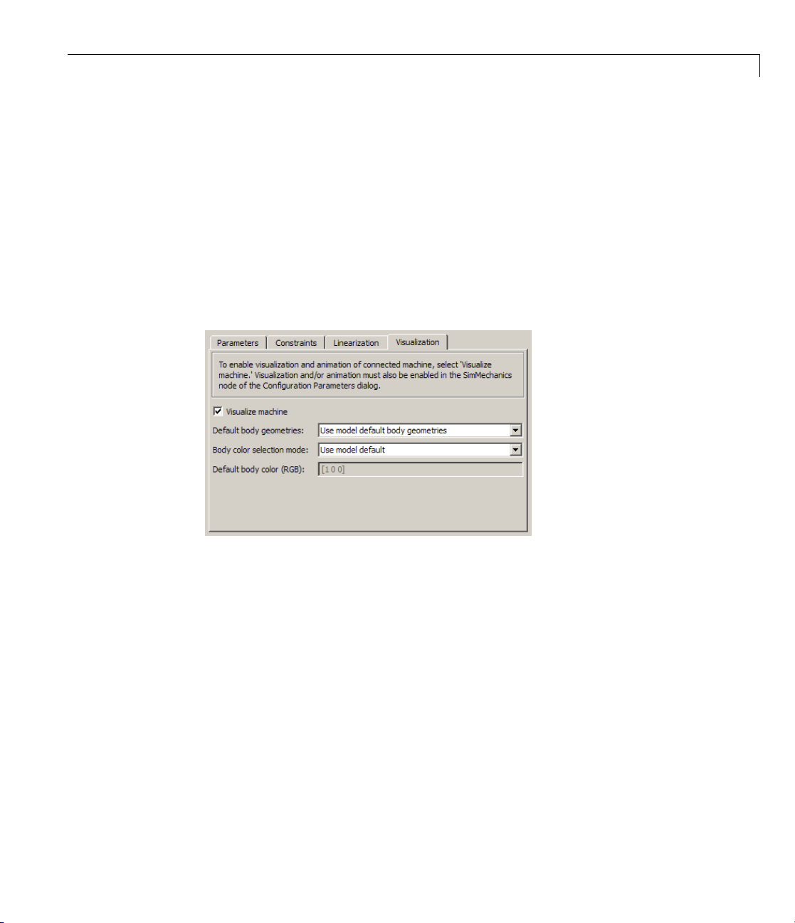
Visualizing All Bodies in a Machine
You can choose whether or not to visualize a specific machine in your model
through the Visualization tab of its Ma ch in e Environment block dialog. A
single window displays all selected machines in a model.
By default, each machine is selected for visualization. If you turn off machine
visualization, your choice only affects that machine, not the entire model.
Other Si mMechanics Visualization Controls
All other visualization controls are located on the SimMechanics visualization
window itself. You can access them once the window is open, as discussed in
Chapter 2, “Getting Started with the Visualization Window”.
You control custom visualization choices for individual bodies in their
respective Body dialogs.
Using SimMechanics Visualization
The visualization chapters guide you in making appropriate SimMechanics
visualization choices, includ in g why you might want to visualize y o u r model’s
bodies and animate their motion.
1-3

1 Introducing Visualization and Animation
Display Versus Animation
SimMechanics visualization serves two distinct purposes, static and dynamic.
In both cases, you can change your observer viewpoint and navigate through
the scene, as well as change the visualized body properties.
Static Display
You can display a static state of your model at different stages of modeling.
Use static display in the initial state, during construction. Either:
• Open the visualization before or while you build your model. You display
each body as you add it to your model, if you also update the block diagram.
Having the visualization window open during model building lets you keep
track of your model’s bodies and how they are connected. Yo u can see
unphysical or mistaken constructions before you finish the model.
• Open the visualization after you finish the model. All the bodies in the
model appear together.
1-4
Also use static display after a simulation ends, or after you pause or stop
it. In these cases, the visualization window shows the model at later times
or in the final state.
Dynamic Animation
You can also display an animation of body motion while the Si m M echanics
model is running. Use this feature to watch the model’s dynamics in three
dimensions and visualize motions and relationships more easily than is
possible with Scope blocks alone.

About Body Color and Geometry: Default, Standard, and Custom
About Body Color and Geometry: Default, Standard, and
Custom
In this section...
“About Body Color: Default and Custom” on page 1-5
“About Body Geometry: Default, Standard, and Custom” on page 1-5
“Standard Bo dy Geometry: Equivalent Ellipsoids” on page 1-5
“Standard Body Geometry: Convex Hulls” on page 1-9
“Custom Body Geometry and External Graphics Files” on page 1-10
About Body Color: Default and Custom
The initial default color of all visualizedbodiesisred. Youcanmodifythis
default or replace it by custom colors for individual bodies, one at a time. See
Chapter 3, “Customizing Visualization and Animation”.
About Body Geometry: Default, Standard, and Custom
You can choose how the visualization window displays the bodies in size and
shape ( ge ometry ). There are two available standard geometries:
• Equivalent ellipsoid for each body, based on its mass properties and center
of gravity (CG) position
• Convex hull for each body, based on its Body coordinate systems (CSs)
The convex hull geometry is the initial default body geometry for all visualized
bodies.
Standard Body Geometry: Equivalent Ellipsoids
The inertia tensor I of a rigid body is real and symmetric, so it has three real
eigenvalues (I
are the principal axes of the body. In the coordinate system defined by those
axes, the inertia tensor is diagonal. The trace of the inertia tensor, Tr(I)=
, I2, I3) and three orthogonal eigenvectors. These eigenvectors
1
1-5

1 Introducing Visualization and Animation
I1+ I2+ I3, i s the same in any coordinate system with its origin at the body’s
center of gravity (CG).
Every rigid body has a unique equivalent ellipsoid, a homogeneous solid
ellipsoid of the same inertia ten sor. In Cartesian coordinates, the ell ip soid
surface is given by
⎡
⎣
⎛
⎜
⎝
y
a
()
2
⎞
⎟
⎠
2
z
()
a
−
⎤
()
⎦
1
2
x
++=
()
a
xyz
where m isthebody’smass. Thethreeparameters(ax, ay, az)arethe
generalized radii of the ellipsoid. For axis i = 1,2,3,
aTrIm
=
522I
ii
Triangle Inequalities
The principal moments (I1, I2, I3) must satisfy the triangle inequalities:
II I
+≥
231
III
+≥
31 2
II I
+≥
12 3
Violation of the triangle inequality for Iileads to an unphysical imaginary
generalized radius a
Caution Visualizing the equivalent ellipsoid of a body whose principal
moments do not satisfy the triangle inequalities leads to a SimMechanics
warning indicating that one or more triangle inequalities have been violated.
The simulation continues, but the body in violation is not displayed.
.
i
1-6
Ellipsoids with Special Symmetry
In general, all three Ii, i = 1,2,3, are unequal. Such a body is an asymmetric
top. If two of the three I
symmetric top. Thethirdaxisistheaxisofsymmetry. IfallthreeI
are equal (double degeneracy), the bo dy is a
i
are equal
i

About Body Color and Geometry: Default, Standard, and Custom
(triple deg eneracy), the body is a spherical top and dynamically equivalent to
a homogeneous sphere.
Reduced-Dimension Ellipsoids
In special cases, the equivalent ellipsoid reduces to a planar, linear, or p oint
figure.
Let (i,j,k) label the three axes (1,2,3) = (x,y,z)inanyorder.
• For a true ellipsoid,withnonzerovolume,allthea
are nonzero. Th e
i
triangle inequalities are strict inequalities in this case:
II I
+>
jki
III
+>
ki j
II I
+>
ijk
• For an ellipse, with zero volume but nonzero area, one ai=0andtheother
two a
, akare nonzero. One of the triangle inequalities beco m es an equality:
j
II I
+=
jki
III
+>
ki j
II I
+>
ijk
• For a line, with zero volume and area but nonzero length, two ai, aj=0and
the third a
II I
jki
III
ki j
II I
+>
ijk
is nonzero. Two of the triangle inequalities become equalities:
k
+=
+=
Equivalently, Ii= Ijare nonzero and Ik=0.
• For a point,withnospatialsize,allthreea
inequalities become equalities:
vanish. All three triangle
i
1-7

1 Introducing Visualization and Animation
II I
+=
jki
III
+=
ki j
II I
+=
ijk
Equivalently, all three Iivanish.
Example: Simple Pendulum Rod
Consider the simple pendulum rod in “Visualizing a Simple Machine” in the
SimMechanics Getting Started Guide.Youcanopenthemodelbyentering
mech_spen at the command line.
The rod length L =1m,anditsradiusr = 1 cm. The inertia tensor is
I
⎛
⎜
⎜
⎜
⎝
00
xx
I
00
yy
00
2
⎛
mr
⎞
⎟
=
⎟
⎟
I
zz
⎠
20 0
⎜
⎜
0120
⎜
⎜
00 12
⎝
mL
2
mL
⎞
⎟
⎟
⎟
2
⎟
⎠
1-8
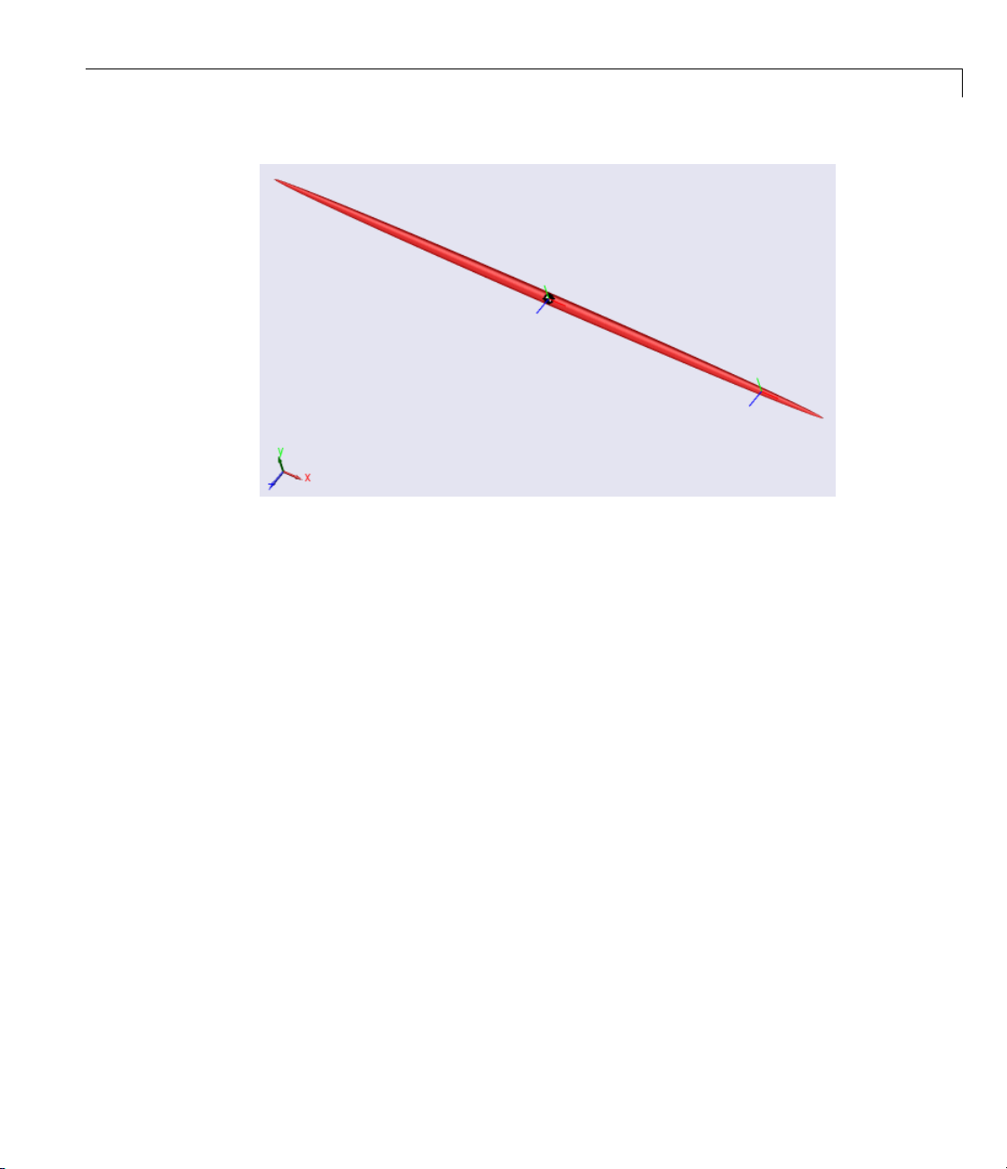
Because the rod has an axis of symmetry, the x-axisinthiscase,twoofits
three p rincipal moments are equal: I
radii are equal: a
= az. The rod is a symmetric top and, since r is much smaller
y
= Izz, a nd two of its three generalized
yy
than L, its equivalent ellipsoid is almost a line of zero volume and area.
53 2L
The ge ne raliz ed radii of the equivalent ellipsoid are a
52r
and a
= az=
y
()
= 1.12 cm. This is the rod so displayed:
=
x
()
= 0.646 m
About Body Color and Geometry: Default, Standard, and Custom
Standard Body Geometr y: Convex Hulls
Every Body has at least one Body coordinate system (CS) at the CG. A
Body also has one or more extra Body CSs for the attached Joints, as well
as possible Actuators and Sensors. Each Body CS has an origin point, and
the collection of all these points, in general, defines a volume in space. The
minimum outward-bending surface enclosing such a volume is the convex hull
of the Body CSs, and this is the alternative standard body geometry. The
SimMechanics convex hull excludes the CG CS.
To enclose a nonzero volume, this set must have at least four non-coplanar
Body CSs. Three non-collinear Body CSs are displayed instead by a triangle,
and two non-coincident origins by a line. One origin is displayed just as
apoint.
Four or more coplanar origins are displayed as a triangle, three or more
collinear origins are displayed as a line, and two or more coincident origins
are displayed as a point.
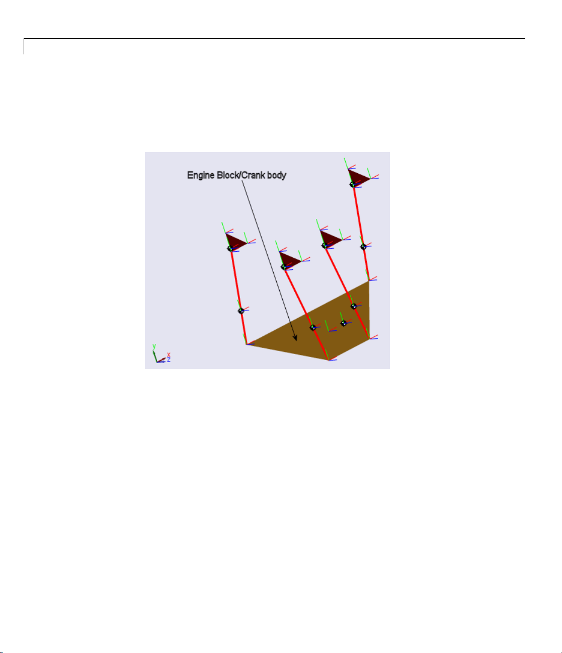
Example: Four-Cylinder Engine Crank
Open the four-cylinder engine model by entering mech_fceng at the command
line. Start visualization.
1-9
1 Introducing Visualization and Animation
Open the Engine Block subsystem and note the Crank block representing the
engine crank. This Body block has five coplanar Body CSs, not including the
CG CS. Visualize the engine as convex hul ls and click the Crank body, the
largest body. The convex hull forms a planar polygon.
1-10
Custom
In plac
geomet
s. See Chapter 3, “Customizing Visualization and Animation”.
bodie
Body Geometry and External Graphics Files
e of the standard body geometry choices, you can provide a custom
ry defined with external graphics files for one or more individual

Hierarchy of Bod y, Machine, and Model Visualization Settings
Hierarchy of Body, Machine, and Model Visualization
Settings
In this section...
“Visualized Geometries and Colors from Body Block Settings” on page 1-11
“BodyBlockSettingsAffectingBodyVisualization”onpage1-12
“Visualization Settings in the Machine and Model Hierarchy” on page 1-13
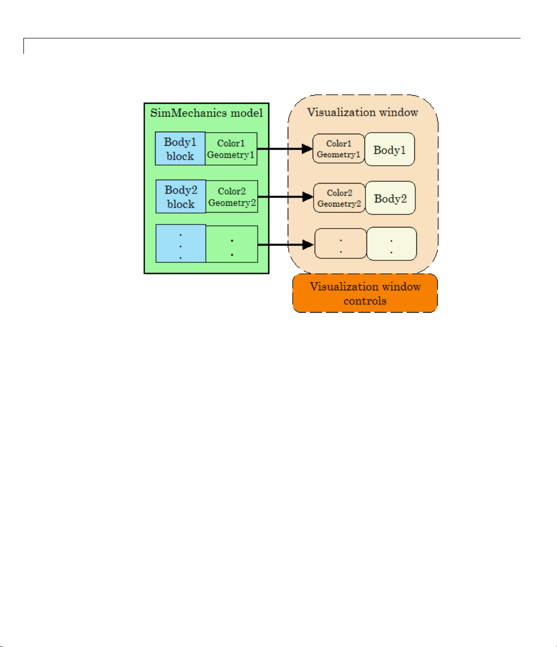
Visualized Geometries and Colors from Body Block Settings
The SimMechanics visualization window visualizes bodies repre s en ted by
Body blocks in your model. The visualization information that the window
uses from the model comes strictly from the mass, coordinate system, and
visualization properties set individually in each Body block’s dialog.
Note The window itself contains addi t ion a l visualization controls that affect
visualized body geometries and colors. See Chapter 2, “Getting Started with
the Visualization Window”.
1-11
1 Introducing Visualization and Animation
1-12
Body Block and V isu al ization Window Setti ngs Control Body Visualization
Body Block Settings Affecting Body Visualization
How settings in Body block dialogs affect visualization depends on which type
of body geometry and which color you ch oose for a particular body. The Body
dialog contains three classes of such choices.
Mass Properties
The principal inertial moments and the mass of a body determine the size
and shape of its equivalent ellipsoid.
Body Coordinate Systems: Origins and Orientation
The relative positions of the Body’s coordinate systems (CSs) determine the
size and shape of its convex hull.
Visualization
The color choice in the Body dialog’s Visualization tab determines the color
of the visualized body.

Hierarchy of Bod y, Machine, and Model Visualization Settings
You make the choice of convex hull or equivalent ellipsoid to visualize an
individual body in the Body dialog’s Visualization tab.
If you choose a custom body geometry for a Body, the external body geometry
file referenced in the Body dialog’s Visualization tab determines the
visualized body’s size and shape .
Note The choice of standard or custom body geometry has no effect on the
visualized body’s color. The choice of body color has no effect on the visualized
body’s geometry.
Visualization Settings in the Machine and Model Hierarchy
SimMechanics models start with initial default visualization settings. A
model a nd machines within the model also possess, respectively, model-wide
and machine-wide default visualization settings. Visualization settings are
inherited from the highest level (model) through machines to individual
Bodies. You can change these default and inherited settings.
Chapter 3, “Customizing Visualization and Animation” discusses the controls
you need to adjust to change these default and inherited settings at the
model, machine, and body levels.
1-13

1 Introducing Visualization and Animation
1-14
Inheritance Hierarchy of Default Visualization Settings
Initial Default Settings for a Model
The initial default visualization settings for an entire model are:
• Model-wide default body color: red (RGB value o f
• Model-wide default body geometry: convex hull
[1 0 0])
Machine Inheritance of Model-Wide Default Settings
The initial default visualization settings for a m achine are:

Hierarchy of Bod y, Machine, and Model Visualization Settings
• Machine-wide default body color: inherit model-wide default
• Machine-wide default body geometry: inherit model-wide d efault
Body Inheritance of Machine-Wide Default Settings
The initial default visualization settings for a Body are:
• Default Body color: inherit machine-wide default
• Default Body geometry: inherit machine-wide default
1-15

1 Introducing Visualization and Animation
1-16

Getting Started with the Visualization Window
The SimMechanics visualization window allows you to control how you view
yourmodel’sbodiesinbothstaticdisplay and dynamic simulation-based
animation. It also allows you to record animations.
• “Introducing the SimMechanics Visualization Window” on page 2-2
• “Controlling Body and Body Component Display” on page 2-6
2
• “Adjusting the Camera View” on page 2-9
• “Communicating with the Model from the Visualization Window” on page
2-17
• “Controlling and Timing Simulation from the Visualization Window” on
page 2-21
• “Controlling Animation” on page 2-23
• “Recording Animation” on page 2-28
• “Visualization Menus and Their Controls” on page 2-33

2 Getting Started with the Visualization Window
Introducing the SimMechanics Visualization Window
In this section...
“About the Visualization Window” on page 2-2
“Opening and Updating the Visualization Window” on page 2-2
“Visualization Toolbar and Its Controls” on page 2-4
About the Visualization Window
The visualization window is an integral part of SimMechanics software. With
it, you can visualize y our machines using a comprehensive set of display
controls, interact with your model, and watch and record animations.
The window uses a distinctive set of symbols and shapes to display bodies and
Body coordinate systems (CSs). This section is an overview of what you can
do with the SimMechanics window.
2-2
Caution The S imMechanics visualization window resembles a MATLAB
Graphics figure window. But it is not a feature of MATLAB and has no figure
handle.
®
Opening and Updating the Visualization Window
Starting visualization and choosing the default display options are discussed
in “About SimMechanics Visualization” on page 1-2.
• Once you configure your SimMechanics model for visualization, select
Update Diagram from the model’s Edit menu (or press Ctrl+D).
The window opens and displays the machines in your model that you
have chosen to visualize. O n e window displays all selected machines
simultaneously.
• To synchronize the static visualization display with you r model, reselect
Update Diagram at any time.
This figure shows a model with the default background color.
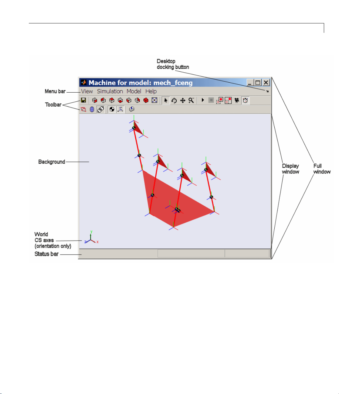
Introducing the SimMechanic s ™ Visualization Window
SimMechanics™ Visualization Window Displaying a Four-Cylinder Engine (Isometric V iew)
Menu Bar Versus Toolbar Controls
Onceyouopenthevisualizationwindow,youhavetwowaystocontrolthe
display and carry out these tasks:
• Use the buttons in the toolbar. Every feature on this toolbar occurs in the
menus, although the reverse is not true. See “Visualization Toolbar and
Its Controls” on page 2-4.
2-3

2 Getting Started with the Visualization Window
• Use the menus in the menu bar. The menu contains specialized items and
submenus. See “Visualization Menus and Their Controls” on page 2-33.
Note Changing the display settings using the visualization window controls
changes only your immediate view in the display window. By itself, it does
not change the visualization settings in the model.
Ifyouwanttosaveachangeinthevisualization window settings to the model,
and thus change the model’s visualization settings, see “Communicating with
the Model from the Visualization Window” on page 2-17.
Visualization Toolbar and I ts Controls
You can activate or change most visualization features by selecting buttons on
the window toolbar, instead of selecting items from the menus. The setting
changes initiated by the toolbar are the same as the corresponding menu
actions: either you activate a feature, enable or disable a feature, or initiate
an immediate action.
2-4
Hovering your mouse cursor over a toolbar button displays the button’s tooltip
indicating its function.
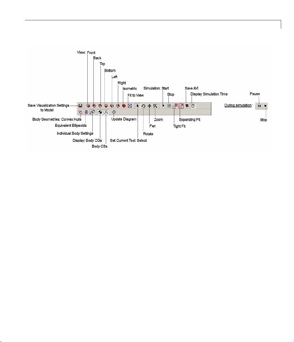
SimMechanics™ Toolbar Buttons
Introducing the SimMechanic s ™ Visualization Window
Toolbar Relationship to the Menus
You can access all of the toolbar functions in the menus as an alternative. The
toolbar reproduces most of the menu functions.
See “Visualization Menus and Their Controls” on page 2-33 for a complete
overview of the visualization window controls.
2-5

2 Getting Started with the Visualization Window
Controlling Body and Body Component Display
In this section...
“About Body and Body Component Display” on page 2-6
“Interpreting the Body Display Symbols and Shapes” on page 2-6
“Changing Body Display Symbols” on page 2-7
“Changing Body Display Shapes” on page 2-7
About Body and Body Component Display
You can change how bodies look in the SimMechanics visualization window.
This section explains how to control body and body compo n ent display.
Interpreting the Body Display Symbols and Shapes
When a visualization window opens, it uses distin ctive conventions to display
the bodies of your model.
2-6
Body Component Display
Body components are d isplayed with two distinctive symbols:
• The center of gravity (CG) point of each body is marked by a half-filled
circle-plus symbol
• Each Body coordinate system (CS) is marked by coordinate axis triads. The
color coding is X-Y-Z ax es = RGB = red-green-blue.
.
Controlling Body and Body Component Display
Body Surface Display
The window displays all the bodies of every machine with visualization
enabled. Theentirebodysurfaceisshadedwiththecoloryouchooseforit.Its
shape is one of these:
• Convex hull: a line, one or more joined surface patches, or a closed surface
enclosing a volume
• Equivalent ellipsoid
• A custom shape
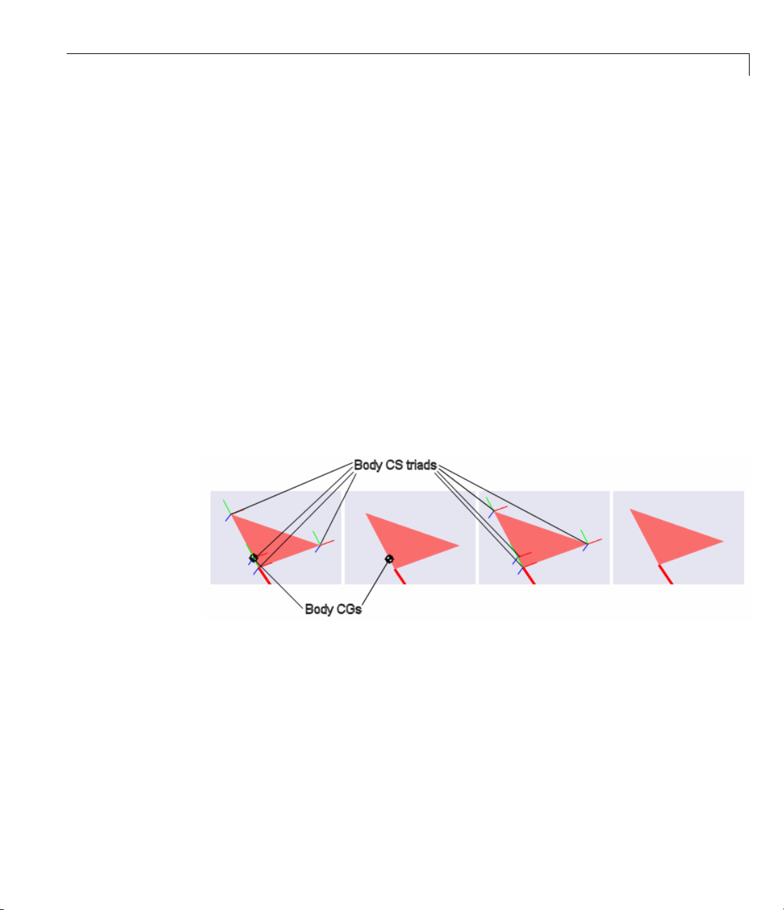
Changing Body Display Symbols
You can turn off the CS triads, the CG symbols, or both using the toolbar,
with the Display Centers of Gravity and Display Coordinate Systems
buttons.
You can activate or deactivate each button separately. The default for both
is active.
Four-Cylinder Engine: Cylinder Piston With and Without Body CS Triads
and CGs (Detail)
Changing Body Display Shapes
You can switch among three possible display shape options using the toolbar.
They are mutually exclusive; one is always active.
2-7
2 Getting Started with the Visualization Window
• Clicking the Set Body Geometries to Convex Hulls button displays
allbodiesasconvexhulls,regardless of the visualization settings in the
Body blocks in the model.
• Clicking the Set Body Geometries to Ellipsoids button displays all
bodies as convex hulls, regardless of the visualization settings in the Body
blocks in the model.
• Clicking the Set Body Geometries to Individual Body Settings button
displays each body according to the visualization settings in its Body block
in the model. This is the default.
2-8
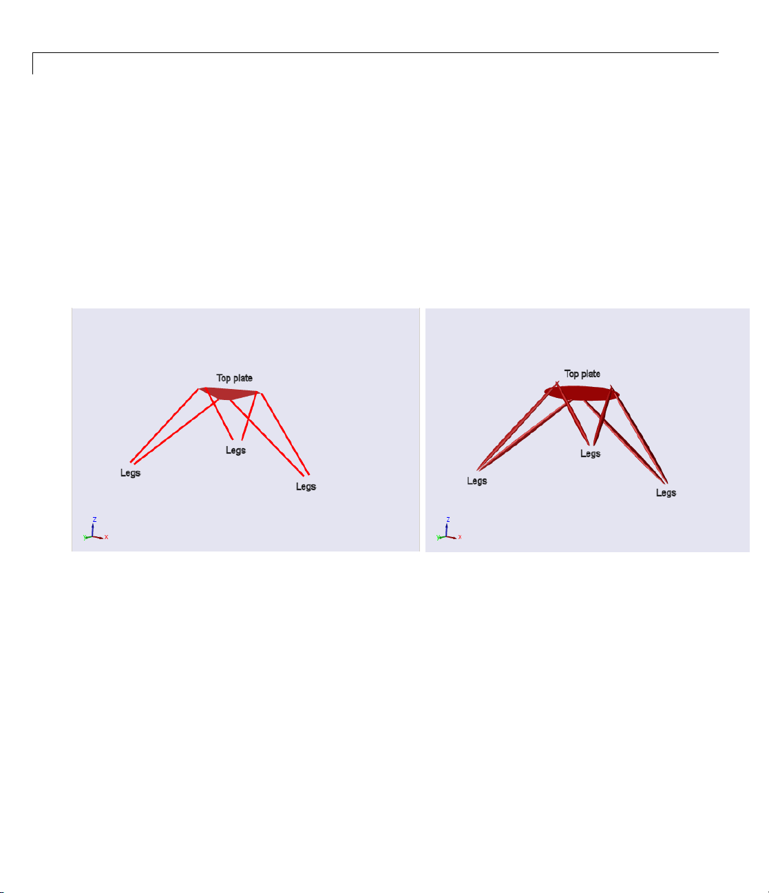
rt Platform: Bodies Displayed as Convex Hulls and as Equivalent Ellipsoids
Stewa

Adjusting the Camera V iew
In this section...
“Setting the Background Color” on page 2-9
“Interpreting the Camera Projection, Field of View, and Viewpoint” on
page 2-9
“Automatically Sizing the Camera Field of View” on page 2-11
“Automatically Setting a Camera Viewpoint” on page 2-12
“Actively Controlling the Camera Viewpoint” on page 2-13
“Camera Viewpoint and Mouse Contro ls” on page 2-14
Setting the Background Color
You must use the menu bar to change the background color of the display
window within th e SimMechanics visualization window.
Adjusting the Camera View
1 Open View,thenselectChange Background Color. A color palette
opens.
2 Select a color. Click OK to implement your choice. The background color
changes immediately.
The color palette for the background is the same as the palette for custom
body color. See “Customizing Vis ua l ize d Body Colors” on page 3-4.
Interpreting the Camera Projection, Field o f View, and Viewpoint
To properly interpret what you see in visualization, imagine that the display
window shows the field of view of a camera. The properties of this virtual
camera determine most of what you need to know about controlling your
view of the model’s machines.
2-9
2 Getting Started with the Visualization Window
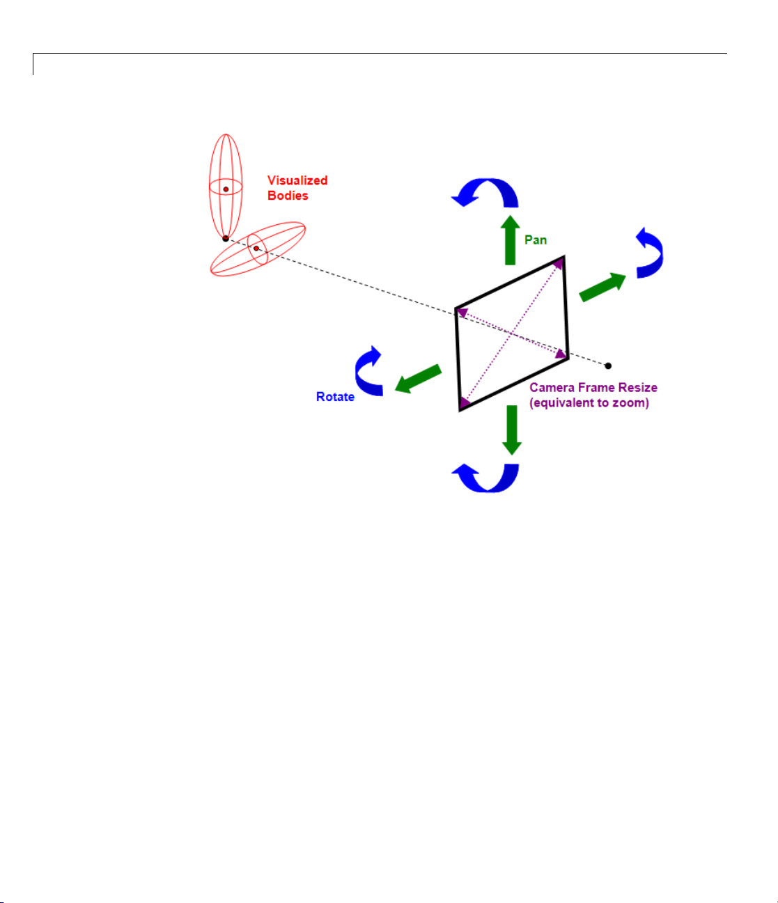
2-10
Visuali
zation Window Camera Field and Visualized Scene
Visualization and Orthographic Projection
The vis
threelines
windo
ualization window uses orthographic (parallel) projection to reduce a
dimensional scene to two dimensio ns on your screen. That is, parallel
of view representing depth converge to a point only at infinity. The
w displays the scene without finite perspective.
Camera Field of View, Viewpoint, and Frame Size
ield of view is what you see within the virtual camera frame. The virtual
The f
ra’s viewpoint is the point and direction from which it views the scene.
came
virtual camera frame has a size or aperture.
The

Adjusting the Camera View
Zooming. Changing the camera frame size or aperture, then shrinking
or expanding the overall size of the machines, is the equivalent of zooming
in or out. The camera cannot zoom directly, because there is no point of
convergence or perspective.
Panning. Panning changes the camera’s virtual location without changing its
direction of view. It means moving the camera frame horizontally or vertically
in a constant virtual plane, maintaining the orientation of the camera frame.
Rotating. Rotating means viewing the scene from a different direction, wh ile
maintaining a constant zoom (effective distance from the machines).
A rotation rotates about the center of the geometric bounding box containing
all the objects in the field of view. (This geometric center is unrelated to
body pro perties , such as Body coordinate systems or centers of gravity.) The
viewpoint is moved to another point on the virtual sphere with this same
geometric center. The view direction changes to maintain the geometric
center at the center of the display window.
World Coordinate System Axes Indicate Orientation Only
The World CS axis triad always appears at the lower-left corner of the display
window.
The directions of the axes indicate orientation only. The position of the axes
does not, in general, indicate the position of the World coordinate system
(CS) origin.
Automatically Sizing the Camera Field of View
You can automatically resize the camera’sfieldoraperturesizetofitallthe
visualized objects. This step is equivalent to an automatic zoom. It d oes not
rotate the viewpoint or pan the camera.
2-11

2 Getting Started with the Visualization Window
To fit the field of view to size, click the Fit to View button on the toolbar. The
camera field resizes itself immediately.
2-12
Automatically Setting a Camera Viewpoint
You can automatically change your viewpoint of the visualized bodies by
clicking one of the six viewpoint buttons on the toolbar. The action applies
immediately.
Clicking these buttons is equivalent to setting a plane of view defined by the
World CS axes. Except for the isometric view, these predefine d viewpoints
always have one a xis perpendicular to the plane of view (pointing into or out
of the plane of view). The isometric view is a viewpoint direction with equal
ection cosines (all
dir
default is the front view, with X pointing right, Y pointing up, and Z
The
nting out of the plane of view.
poi
13/
).

Adjusting the Camera View
Toolbar Button
Front View
(default)
Back View
Top View
Bottom View
Left View
Right View
Isometric View
Axes and Orientation of View Plane
X points right – Y points up
X points left – Y points up
X points rig ht – Z points down
X points right – Z points up
Z points right – Y points up
Z points left – Y points up
X points down and right – Y points up – Z points
down and left
Actively Controlling the Camera Viewpoint
The four selection-viewpoint toolbar control buttons enable certain
interactions between your mouse and the display w indow through
point-and-click or point-click-hold-and-roll.
These four toolbar-menu controls are mutually exclusive; you can activate at
most one of them at a time. The default is for the Select Tool to be activ e.
• Enable a tool by clicking on its button.
• Disable all of them by clicking the currently active tool button.
Function
Select
bodies
Viewpoint
controls
Tool
Select
(default)
Rotate
Pan
Zoom
How to Use
Point with the mouse at a visualized body, then
click on any mouse button.
Point with the mouse anywhere in display window.
Then left-click, holding the mouse button, and roll
mouse.
2-13

2 Getting Started with the Visualization Window
Results of Rolling t he Mouse with the Viewpoint Controls
With one of the three viewpoint control tools enabled, rolling the mouse
produces one of three possible results in the display window.
Rotate Tool. Rolling so that the arrow moves in the display window along
a line, rotates the view about that line. R olling in a more complex figure
rotates the view in a m ore complex way.
Pan Tool. Rolling forward, back, left, or right pans up, down, left, or right,
respectively.
Zoom Tool. Rolling forward or back zooms out or in, respectively. You
zoom toward or away from the point that you initially clicked on. Rolling left
or right does nothing.
ForMoreAbouttheSelectTool
See “Highlighting Bodies, Body Components, and Body Blocks” on page 2-17.
2-14
Camera Viewpoint and Mouse Controls
The four selection-viewpoint tool controls and the computer mouse have a
complementary relationship to each other.
Normal Versus Dynamic Mouse Control
In normal mouse control, the left mouse button’s function corresponds to the
function activated in the menus or toolbar. Depending on which function you
activate from the menu or toolbar, you can switch the left mouse button from
normal to dynamic mouse control and back. “Actively Controlling the Camera
Viewpoint” on page 2-13 explains this case.
In dynamic mouse control, the viewpoint controls are disabled from the menu
or toolbar. (Either the Select Tool is enabled, or all four selection-viewpoint
controls are disabled from the menu or toolbar.) You can still exercise
the viewpoint controls with the three mouse buttons, which are mapped
one-to-one to the viewpoint controls.

Adjusting the Camera View
Note If your mouse has fewer than three buttons, y ou cannot access the
dynamic mouse control functions associated with the missing button or
buttons.
Normal and Dynamic Mouse Control with Left Mouse Button
The left mouse button’s mapping is more complex.
Viewpoint
Control
Normal:
Pan
Normal:
Zoom
Dynamic:
Rotate
Active
If Pan Tool is
enabled from
menu or toolbar
If Zoom Tool is
enabled from
menu or toolbar
If Pan and
Zoom Tools are
disabled from
menu or toolbar
Dyna
The center and right mouse buttons’ mappings are always dynamic.
How to Use
Pan field of view by clicking and holding anywhere in display
window and rolling mouse.
Zoom field of view by clicking and holding anywhere in display
window and rolling mouse.
If Select Tool is
disabled from
menu or toolbar:
If Select Tool
is enabled from
menu or toolbar:
Rotate viewpoint by clicking and holding
anywhere in display window and rolling
mouse.
Rotate
on only
rollin
Click
selec
viewp
viewpoint by clicking and holding
background in display window and
gmouse.
ing on a visualized body in this case
ts the body and has no effect on
oint.
mic Mouse Control with Center and Right Mouse Buttons
2-15

2 Getting Started with the Visualization Window
Mouse
Button
Center
Right Dynamic:
Viewpoint
Control
Dynamic:
Pan
Zoom
Active
If Select Tool is
disabled from
menu or toolbar:
If Select Tool is
enabled from menu
or toolbar:
If Select Tool is
disabled from
menu or toolbar:
If Select Tool is
enabled from menu
or toolbar:
How to Use
Pan field of view by clicking and holding
anywhere in display window and rolling mouse.
Pan field of view by clicking and holding on only
background in display window and rolling m ouse.
Clicking on a visualized body in this case selects
the body and has no effect on field of view.
Zoom field of view by clicking and ho lding
anywhere in display window and rolling mouse.
Zoom field of view by clicking and holding on only
background in display window and rolling m ouse.
Clicking on a visualized body in this case selects
the body and has no effect on field of view.
2-16

Communicating with the Model from the Visualization Window
Communicating with the Model from the Visualization
Window
In this section...
“Highlighting Bodies, Body Components, and Body Blocks” on page 2-17
“Updating the Model Diagram” on page 2-18
“Saving Visualization Settings to the Model” on page 2-19
Highlighting Bodies, Body Components, and Body Blocks
If you have the Select Tool enabled, clicking a body, Body coordinate system
(CS),orBodycenterofgravity(CG)in the SimMechanics visualization
window causes the following:
• The displayed body or body component changes color:
- A selected body surface or CS triad becomes yellow.
- A selected CG changes from white-black to yellow-black.
• The visualization window displays the associated Body block or Body CS
name and its path at the low er left just below the display window, in the
status bar.
• The associated Body block is outlined in red in the model window.
To unhighlight, click the highlighted body again. You can select and highlight
a body both in static displ ay and during simulation.
2-17

2 Getting Started with the Visualization Window
SimMechanics™ Visualization Window with Highlighted Body and Body Block (Four-Cylinder
Engine)
Enabling and Disabling Highlighting
You can enable or disable the highlighting of model Body blocks from the
Model menu item Enable Model Highlighting. The default is enabled.
Whether model highlighting is enabled or disabled, clicking a body or
body component in the window always highlights it. If you disable model
highlighting, the associated Body block is not highlighted when you click the
displayed body or body component.
Updating the Model Diagram
You can update your Simulink model diagram from the model toolbar or Edit
menu, or by pressing Ctrl+D from the keyboard.
You can also update it by clicking the Update Simulink Diagram button
in the visualization window toolbar.
2-18

Communicating with the Model from the Visualization Window
Saving Visualiz
As you work with t
setting changes
• Changes you mak
while the wind
then upon reop
whatever mode
Machine, and
• If you want to
controls be
the Save Vis
window tool
the model it
• If you want
you must sa
model too
lbar.
he visualization settings, you might want to save the
that you make.
e to the visualization settings apply only to the display
ow is open. If you do nothing else and close the window,
ening the visualization window, the display will revert to
l requires for visualization settings. See “Hierarchy of Body,
Model V isualization Settings” on page 1-11.
save the display setting changes you made from the window
fore closing the window, you must save them to the model. Click
ualization Settings to Model buttononthevisualization
bar. A warning dialog ap pears, asking if you want to save
self.
to save these display setting changes before closing the model,
ve or resave the model itself. Click the Save button in the
ation Settings to the Model
2-19

2 Getting Started with the Visualization Window
2-20
Caution If the changes to the display settings include changing the
displayed body geometries, the saved visualization settings will make the
visualization window display whatever the setting requires (all conve x hulls,
all equivalent ellipsoids, or individual body geometries). But the saved
visualization display settings do not change the visualization settings at the
model, machine, or Body block level in the model described in Chapter 1,
“Introducing Visualization and Animation”.

Controlling and Timing Simulation from the Visualization Window
Controlling and Timing Simulation from the Visualization
Window
In this section...
“Starting, Pausing, a nd Stopping the Simulation” on page 2-21
“Timing the Simulation” on pag e 2-21
Starting, Pausing, and Stopping the Simulation
You can control a simulation from the SimMechanics visualization window
with the pair of simulation control buttons. The pair takes two different
appearances, depending on whether the simulation is running.
With Simulation Stopped
From left to right, the buttons are Start and Stop,withStop disabled:
.
With Simulation Running
From left to right, the buttons are Pause and Stop: .
• If you pause a running simulation, restarting it begins the simulation at
the simulated time when it was stopped.
• If you stop a running simulation, restarting it begins the simulation at a
simulated time of zero.
Timing the Simulation
Once you start the simulation, you can track the simulation time at the
lower right of the visualization window, in the status bar, if the simulation
time display is active.
2-21

2 Getting Started with the Visualization Window
2-22
Simulation Time Display (Robot Arm Simulation with Visualized Body CSs
and CGs Deactivated)
Activating and Deactivating the Simulation Time Display
You can activate or deactivate the simulation time display using the Display
Simulation Time button on the toolbar. The default is active.

Controlling Animation
In this section...
“About Animation” on page 2-23
“How Animation Works” on page 2-23
“Automatically Adapting the Camera View to the Displayed Motion” on
page 2-24
“Changing How the Animation Is Updated” on page 2-25
“Speeding Up the Animation in Real Time” on page 2-27
About Animation
When you start a simulation with visualization and animation enabled, the
SimMechanics visualization window displays the body motion. This section
shows how you can control the animation.
Controlling Animation
How Animation Works
The v isualization window displays the animated bodies in whatever camera
view you previously set before starting simulation. By default, the cam era
remainsatrestinWorld.
The animation that you see in the display window is the result of three
distinct processes operating in parallel.
• Simulink
• Simulink updates the model outputs at every output sample time step.
• During animation, the visualization window updates the display of the
bodies at every visualization sample time step.
Each updated, displayed simulation scene is also called a frame.
By default, the output sample times are every major time step, and the
visualization sample times are the output sample tim es. But, within limits,
you can change the relationships among these time steps.
®
updates the model simulation at every simulation time step.
2-23

2 Getting Started with the Visualization Window
Caution Because visualization needs the model outputs to update the
animation, the visualization sample time should be equal to or longer than
the m odel output sample time. If the visualization sample time is shorter, the
displayed animation is updated at the model output sample times.
Automatically Adapting the Camera View to the Displayed Motion
As the bodies move in the animation, the camera view you set for the static
case before simulation might not encompass their full range of motion. Or the
bodies might move out of the field of view altogether.
You can require the display window to adapt the field of view dynamically
to the animation with the Enable Automatic Expanding Fit and Enable
Automatic Tight Fit buttons on the toolbar. These buttons are mutually
exclusive. The default for both is disabled.
2-24
Allowing the Field of View to Expand with the Moving Bodies
If the animated bodies tend to move out of the field of view once, repeatedly, or
continually, click the Enable Automatic Expanding Fit button. The field
of view will then expand as necessary to encompass the geometric bounding
box of all the bodies, as visualized. The camera remains at rest in World.
Keeping the Field of View Limited to the Moving Bodies
If you want your field of view to encompass just the moving bodies and track
them as they move, click the Enable Automatic Tight Fit button. The
center of the field of view will remain fixed to the center of the geometric
bounding box of all the bodies, as visualized. The camera is no longer at rest
in World, but continually zooms and pans to track this geometric center.

Controlling Animation
Caution With automatic tight fit enabled, the observer’s reference frame is
no longer at rest in World and, in general, is noninertial. The motion of bodies
thatyouseeisnotthatseenbyanobserverinWorld.
This autom atic tight fit can create the illusion that the bodies as a whole are
not moving. Disable the automatic tight fit to check if this is the case.
Changing How the Animation Is Updated
You might find it convenient to change how quickly the animation in the
display window responds to changes in the simulation, especially if the
animation is going by to o fast in real (clock) time.
You can change most of these con trols by going to the Simulation menu in
themenubar,thentoControl Animation Speed. The Animation Speed
Control Parameters dialog box opens. You can apply any changes and close
the dialog by clicking OK.
Delaying the Simulation at Every Display Update
At each update of the animation display, the SimMechanics simulation is
delayed for some (simulated) time to allow you to follow the motion. You can
change this delay time in the Animation Speed Control Parameters dialog.
Enter a nonnegative time (in milliseconds) in the Delay per frame field.
The default is
3 (ms).
Changing the Visualization Sample Time
You can break the default connection between visualization and model output
sample times in the Animation Speed Control Parameters dialog as well.
Enter a specified visualization sample time (in seconds) in th e Visualization
sample time field. This time is simulated (not real) time.
The default is
time, and the visualization is effectively updated at the output sample times.
Require the visualization explicitly to inherit the model output sample time
by entering
0 (s). This is smaller than any positive model output sample
-1.
2-25

2 Getting Started with the Visualization Window
Changing the Model Output Sample Time
You can also change the effective visualization sampling rate by changing the
model output sample time in the model’s Configuration Parameters dialog
and leaving the visualization sample time to be whatever the model output
sample time is. This time is simulated (not real ) time.
1 Open the Configuration Parameters dialog from the Simulation menu of
your model window.
2 On the Data Import/Export node, in the Save options area, change the
Output options pull-down menu entry to
.
only
3 Use the Output times field on the right to specify explicitly how often
Simulink should capture the simulation output. In this field, enter a vector
ofsampletimes.Thesampletimerangemustbethesameasorliewithin
the Start time and Stop time range of the Simulation time area in th e
Solver node of Configuration Parameters.
Produce specified output
2-26
If you want a uniform output sampling, use the
linspace command to specify
thetimerangeandnumberofsamplepoints:
linspace(start-time, end-time, number-of-points)
Forexample,tosample200pointsfrom0to10seconds:
1 Open Configuration Parameters f rom the Simulation menu.
2 Locate Output options in the Data Import/Export node. Change the
pull-downmenuto
3 Enter linspace(0,10,200) in the Output times field. Click Apply or OK.
Produce specified output o nly.
Tip This approach does change two distinct model features at once. Changing
the visualization sample time by itself (preceding) has the advantage of
letting y ou specify the model output sample time separately.
See the Simulink documentation for more about model output sample time.

Controlling Animation
Speeding Up the A
As the simulatio
make the animati
n animates the bo dies’ motions, it might slow down. You can
on computationally less demanding with these measures.
nimation in Real Time
Skipping Frames
By default, th
fixed number o
From the Simu
Animation Sp
frames per u
default is
Using fewe
simulatio
e animation displays every updated frame. But you can skip a
f frames between displayed frames.
lation menu, select Control Animation Speed.Inthe
eed Control Parameters dialog, change the Number of skipped
pdate field to a positive integer to specify this number. The
.
0
r sample points leads to a more disjointed animation, but a faster
n and a smaller recorded animation file.
Turning Off Visualization Features
You can sp
• Body cen
• Body coo
eed up the animation if you turn off one or both of these symbols:
ters of gravity (CGs)
rdinate systems (CSs)
The pre
page 2-
You ca
displ
the Vi
ceding section, “Controlling Body and Body Component Display” on
6, explains how to control their display.
nalsospeeduptheanimationbyturning off the simulation time
ay. See the preceding section, “Controlling and Timing Simulation from
sualization Window” on page 2-21.
2-27

2 Getting Started with the Visualization Window
Recording Animation
In this section...
“About Recording” on page 2-28
“How Recording Works” on page 2-28
“Recording Animations” on page 2-28
“Compressing Animation Recordings” on page 2-30
“Controlling the Size of the Recorded Animation” on page 2-31
“Playing Recordings of Animation” on page 2-31
About Recording
As the SimMechanics visualization window displays the body motion, you can
capture what you see as a recording and save it. This section explains how
to record animations. See the preceding section, “Control li ng Animation” on
page 2-23, for more about animation.
2-28
How Recording Works
If you record an animation, the recording captures e ach updated, displayed
simulation scene as a frame.
Whatever you see in the animated display window, is what the recording
captures, as closely as it can within the limitations of the format.
Recording Animations
When you record an animation from the window, it is stored as a file on your
system in Audio Video Interleave (AVI) format.
Caution Recording an animation overwrites any existing file with the same
name as the AVI file in the same folder. The AVI file write fails if a file of the
same name that is locked by another application exis ts in the same folder.

Recording Animation
Activating and Controlling Animation Recording
• You can activate animation recording by clicking the Store Animation in
AVI File button on the toolbar. The default is deactivated.
If you activate, the AVI File L ocation file browser opens, as discussed next.
• You control recording settings using the Simulation menu.
Specifying the Name and folder of the Animation File
You can specify a location and name for your AVI file recording by selecting
Choose AVI File Location from the Simulation menu. If you activate
recording, an AVI File Location file browser opens and requires you to select a
location and specify an AVI name. The default AVI name for a model called
modelname.mdl is modelname.avi, bu t you can change this default name.
Click Save to complete the AVI file specification.
When you activate recording, this AVI file name appears in the bottom middle
of the full visualization window, below the display, in the status bar.
If y ou cancel the file browser, the recording is canceled as well.
2-29

2 Getting Started with the Visualization Window
2-30
How MAT
The simulation first records a MATLAB movie by capturing the display at
every visualization sample time step. Then, in the termination phase of
your simulation, it converts this movie to AVI format and stores it in the
AVI file. A small AVI Conversion window opens to indicate that conversion
and storage are complete and to display the path of the AVI file. Click OK
to close this prompt.
LAB Records the Animation
Compressing Animation Recordings
You can reduce the size of your AVI file by compressing it. Select Compress
AVI File to activate this feature. The default is active.

Recording Animation
Support Restrictions for Recording Compression
AVI compression is available only on the Windows®platform. MATLAB uses
the Indeo 5 compression algorithm. You must have the corresponding video
codec installed to
• Compress an animation while recording.
• Decompress and play back a compressed animation recording.
Check your operating system configuration for installed video codecs.
Caution YoumusthavetheIndeo5videocodecinstalledtocompressan
animation recording. If you do not have this codec installed, a nimation and
recording proceed, but with compression deactivated.
Controlling the Size of the Recorded Animation
Any technique that reduces the number of visualization samplings and
updates reduces the total stream of animated frames and the size of the
recorded file. See “Controlling Animation” on page 2-23.
Tip If MATLAB runs out of memory while recording an animation, you will
receive a warning. The simulation continues until completion, but recording
is truncated at the simulation time when memory was exhausted.
Useoneofthetechniquesdiscussedtoreducethetotalstreamofanimated
frames and attempt the recording again. The simplest technique is to skip
frames.
Playing Recordings of Animation
You need an AVI-compatible video player to view the recorded file. You can
use the internal MATLAB movie viewer or an external video player.
2-31

2 Getting Started with the Visualization Window
Caution You must have the Indeo 5 video codec installed to decompress and
play back a compressed animation recording.
Matching Playback Speed to Simulation Speed
Your computer will play back an AVI animation recording at 15 frames per
second of real (clock) time, regardless of the simulation speed or visualization
sample time during recording.
To guarantee that the animation playback show the simulation in real (clock)
time, before recording, set:
• The model output sample time to be 1/15th of a second.
• The visualization sample time to be equal to or less than the model output
sample time.
See “Changing How the Animation Is Updated” on page 2-25 for more about
sample times.
2-32

Visualization Menus and Their Controls
In this section...
“About the SimMechanics Visualization Window Menus” on page 2-33
“View Menu” on page 2-34
“Simulation M enu” on page 2-35
“Model Menu” on page 2-38
“Help Menu” on page 2-39
About the SimMechanics Visualization Window Menus
The m enus of the visualization window group similar functions and contain
all visualization functions.
Some menu items have a default setting. Others do not, as indicated by a “—”
entry for the default in the menu tables following.
Visualization Menus and Their Controls
Menu
Group Featur
View
ation
Simul
Model
Help
rsistent Settings Versus Immediate Action
Pe
In most situations, all menu items are enabled in the sense that you can
activate it. In some conditions, a menu item can be disabled, and you cannot
activate it.
Change
view;
Contr
anima
Chan
comm
Get
eorFunction
camera viewpoint or frame; manipulate camera
change background
ol simulation; change dynamic camera response to
tion; record animations
ge dis play of body components and geometries; change
on visualization-model features
visualization help
2-33
2 Getting Started with the Visualization Window
Some menu items control a persistent setting and switch between active and
not active; for example, Enable Model Highlighting. By selecting the item,
you either activate it, and a check mark appears; or you deactivate it, and
the check m ark disappears.
Othermenuitems,whenyouselectthem,insteadtriggeranimmediate
action, for example, Simulation > Start.
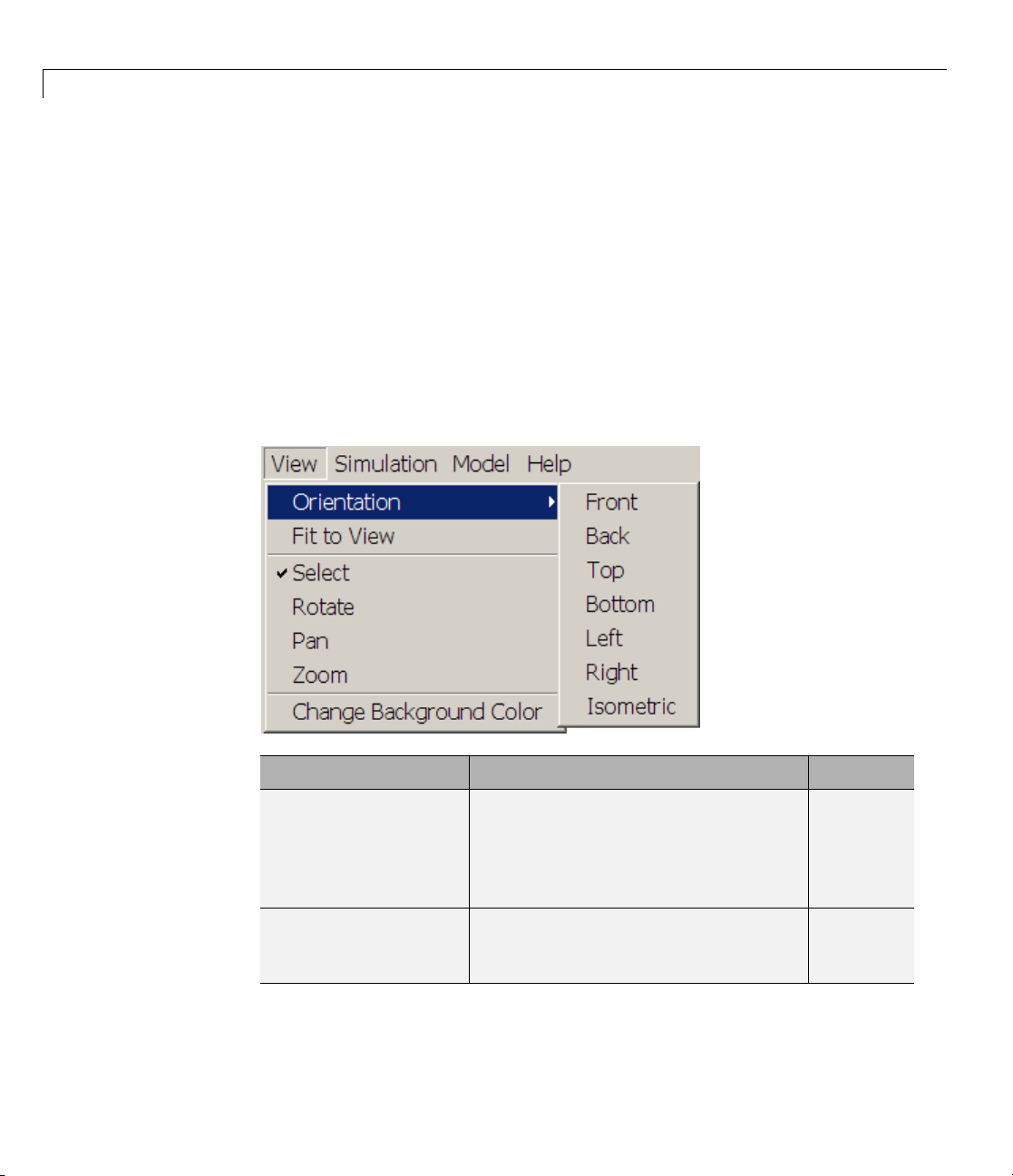
View Menu
This menu allows you to control two distinct visualization features, the
camera viewpoint and frame and the background color.
2-34
Menu Item
Orientation
submenu:
Front, Back, Top,
Bottom, Left, Right,
Isometric
Fit to View
Function
Set camera viewpoint.
Onechoiceisalwaysactive,andthe
choices are mutually exclusive.
Resize camera field to closely fit the
bodies as viewed.
Applies immediately.
Default
Front
—
Visualization Menus and Their Controls
Menu Item
Current Tool:
Select Select objects in the display window. Selected
Rotate
Pan
Zoom
Change
Background Color
Function
Enable mo us e point-and-click tool.
The choices are mutually exclusive,
and can all be unselected
(deactivated).
Rotate camera viewpoint. Unselected
Pan camera field laterally and
vertically.
Zoom in and out of camera field.
Open color palette to choose
background color.
Default
—
Unselected
Unselected
—
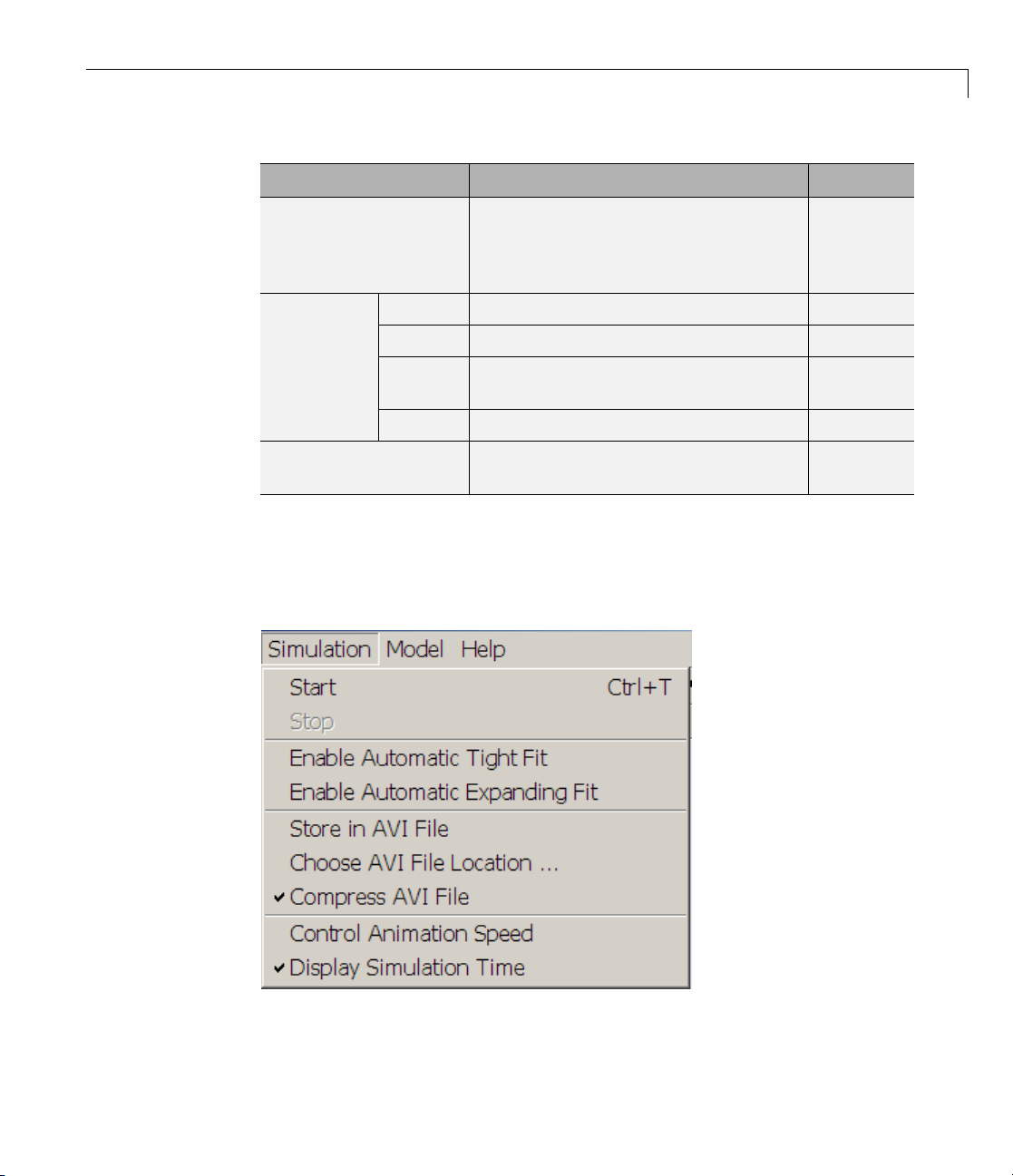
Simulation Menu
Thismenuallowsyoutocontrolthesimulation,thedynamiccamerafield,
and the recording of the animation.
2-35

2 Getting Started with the Visualization Window
Menu Item
Simulation
start,
pause,
and stop
Dynamic camera field Enable adaptive dynamic cam era field
Start Start simulation. Appears and enabled
Pause
Stop Stop simulation. Enabled only when
Enable
Automatic
Tight Fit
Enable
Automatic
Expanding
Fit
Function
only w hen simulation is stopped.
Applies immediately. Keyboard equivalent
is Ctrl+T.
Pause simulation. Appears and enabled
only w hen simulation is running.
Applies immediately.
simulation is running.
Applies immediately. Keyboard equivalent
is Ctrl+T.
during animation.
The choices are mutually exclusive, and
can all be unselected (deactivated).
Enable automatic resizing and zooming
of camera field to keep moving bodies in
fit-to-view field at all simulation times.
Virtual camera moves with overall model
motion with respect to World.
Enable automatic expansion of camera
field to keep moving bodies in field at all
simulation times.
Virtual camera remains at rest w ith
respect to W orld.
Default
—
—
—
Fixed camera field,
viewpoint, and zoom;
camera at rest in
World.
Unselected
Unselected
Store in AVI File Record and save animation in AVI file.
Choose AVI File
Location
Compress AVI File Apply compression to saved AVI recording
Choose nondefault location for AVI file. Default location
of animation.
2-36
Unselected
for saved AVI file
is current working
MATLAB folder.
Selected

Visualization Menus and Their Controls
Menu Item
Control Animation
Speed
Display Simulation Time Show simulation time in lower-right corner
Function
Opens Animation speed control parameters
dialog.
Applies immediately.
of full w indow.
Start–Pause–Stop Menu During Simulation
During simulation, the start–pause–stop part of the Simulation menu looks
like this:
Default
Visualization
sample time (s)
Delay per
frame (ms)
Number
of skipped
frames per
update
Selected
0
3
0
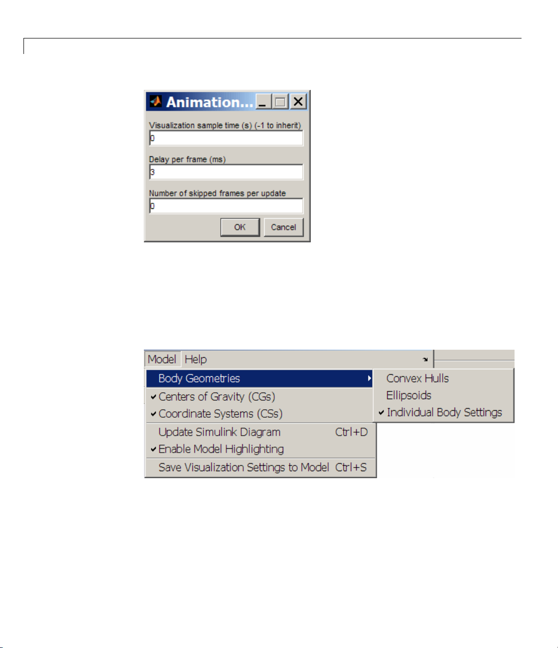
Animation Speed Control Parameters Dialog
The Control Animation Speed m enu item opens the Animation Speed
Control Parameters dialog:
2-37
2 Getting Started with the Visualization Window
See “Controlling Animation” on page 2-23.
Model Menu
This menu allows you to control the display of body geometries and body
components, as well as communicate from the visualization window to the
model.
2-38

Visualization Menus and Their Controls
Menu Item
Body Geometries
submenu:
Convex Hulls
Ellipsoids Visualize all bodies in window as equivalent ellipsoids. Unselected
Individual
Body Setting
Centers of G
(CGs)
Coordinat
(CSs)
Update Si
Diagram
Enable Model
Highlighting
Save Visualization
Settings to Model
ravity
eSystems
mulink
Function
Set geo metries of visualized bodies.
One choice is always active, and the choices are
mutually exclusive.
Visualize all bodies in window as convex hulls. Unselected
Visualize al
s
respective B
Display cen
Display all Body coordinate systems attached to all
visualized bodies.
Apply Upd
immedia
Keyboar
Edit > Up
Enable automatic Body block h ig hlighting when
visualized body is selected in display window.
Save current state of visualization window controls to
model. Applies immediately.
(You need to save the m odel itself to save the settings
permanently.)
l bodies in window according to their
ody block visualization settings.
ters of gravity of all visualized bodies.
ate Diagram command to m odel. Applies
tely.
dequivalentisCtrl+D. Model equivalent is
date Diagram.
Default
—
Selected
Selected
Selected
—
Select
—
ed
Help Menu
This menu allows you to get online help for the visualization window.
Selecting Open Visualization Help immediately opens the Help browser to
the SimMechanics visualization documentation.
2-39

2 Getting Started with the Visualization Window
2-40

Customizing Visualization and Animation
You can customize the colors and geometries of visualized bodies in
the SimMechanics visualization window. Choice of colors is intrinsic to
visualization. Specifying a custom body geometry requires an external
graphics file for each custom ized body.
As an alternative to the visualization window, you can also visualize your
mechanical system with virtual reality.
3
• “About Custom SimMechanics Visualization” on page 3-2
• “Customizing Visualized Body Colors” on page 3-4
• “Customizing Visualized Body Geometrie s ” on page 3-7
• “Visualizing with a Virtual Reality Client” on page 3-13

3 Custom izing Visualization and Animation
About Custom SimMechanics Visualization
In this section...
“Customizing Visualization Settings” on page 3-2
“Creating an External Virtual Reality Client” on page 3-3
Customizing Visualization Settings
You can customize the way that SimMechanics visualization displays bodies,
in terms of their colors and geometry. The geometry is composed of the body’s
size and shape.
• You can adjust the body color on a model- or machine-wide basis, or on an
individual body basis.
• With an external graphics file referenced by a Body block, the visualization
window can visualize the body with whatever shape the graphics file
specifies.
3-2
Starting visualization is discussed in
• Chapter 1, “Introducing Visualization and Animation”
• The SimMechanics User’s Guide
Model- and Machine-Wide Body Color and Geometry Controls
The model–machine–body hierarchy controls the model- and machine-defau lt
body colors and geometries. See “Hierarchy of Body, Machine, and Model
Visualization Settings” on page 1-11.
To control visualization settings for an entire model or machine, you need to
revisit the follow ing two dialogs. These controls a llow you to set a single
default color and a single default standard geometry for all the bodies in a
model or in a machine.
• To set a model-wide default b ody color and geometry, use the Visualization
area of the SimMechanics node of the Configuration Parameters dialog.
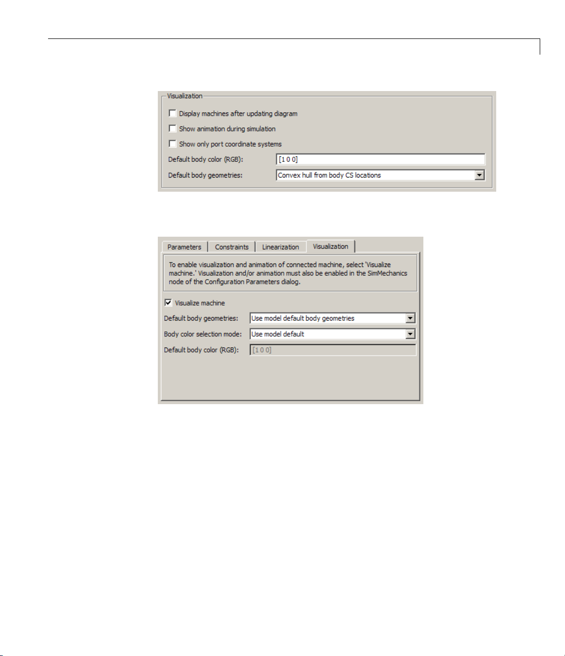
About Custom SimMechanics™ Visualization
• To set machine-wide default body color and geometry, use the
Visualization tab of that machine’s Machine Environment block dialog.
Creating an External Virtual Reality Client
You can bypass standard SimMechanics visualization by creating a virtual
reality world of your own design to visualize your model’s bodies. You can
then build a custom interface from your model to the virtual world and
animate its virtual bodies. See the final section, “Visualizing with a Virtual
Reality Client” on page 3-13.
3-3

3 Custom izing Visualization and Animation
Customizing Visualized Body Colors
In this section...
“Choosing Custom Body Colors” on pag e 3-4
“Switching Betw ee n Default and Custom Body Colors” on page 3-4
Choosing Custom Body Colors
SimMechanics visualization has two formats for specifying a color.
MATLAB ColorSpec Vector
You specify colors by RGB values according to the MATLAB Graphics
ColorSpec for
• An entire model, in the Visualization area of the SimMechanics node of
the Configuration Parameters dialog.
3-4
• An entire machine, in the Visu alization tab of that machine’s Machine
Environment block dialog.
The RGB (red–gre en–blue) triple of values is a vector
value separately satisfying 0 ≤
• Red, green, and blue are
• Black and white are
• Other valid triples specify nonfundamental colors.
[0 0 0] and [1 1 1],respectively.
r, g, b ≤ 1.
[1 0 0], [0 1 0],and[0 0 1],respectively.
[r g b],witheach
Color Palette Interface
You specify colors for individual bodies by visual inspection in the color
palette in their respective Body dialogs.
Switching Between Default and Custom Body Colors
The SimMechanics visualization initial default color for visualized bodies is
red (RGB of
[100]).

Customizing Visualized Body Colors
Changing the Default Color for All Bodies in a Model
You can change the initial default to a different default color for all visualized
bodies in a model.
1 Open the Configuration Parameters dialog, then go to the SimMechanics
node.
2 In the Visualization area, change the Default body color RGB vector to
a different, valid vector of values.
3 Click Apply or OK.
Note You can override the model-wide default body color, both for a whole
machine and for individual bodies.
Changing the Default Color for All Bodies in a Machine
The initial default is for a machine to inherit its model-wide body color. You
can override the initial default by specifying a different machine-wide default
color for all the bodies in one machine in your model.
1 Open that machine’s M achine Environment block dialog and click its
Visualization tab.
2 In the Body color selection mode pull-down menu, choose Specify.The
Default body color field becomes active .
3 Change the RGB vector to a different, valid vector of values.
4 Click Apply or OK.
Note You can override the machine-wide default body color for any
individual body within the machine.
3-5
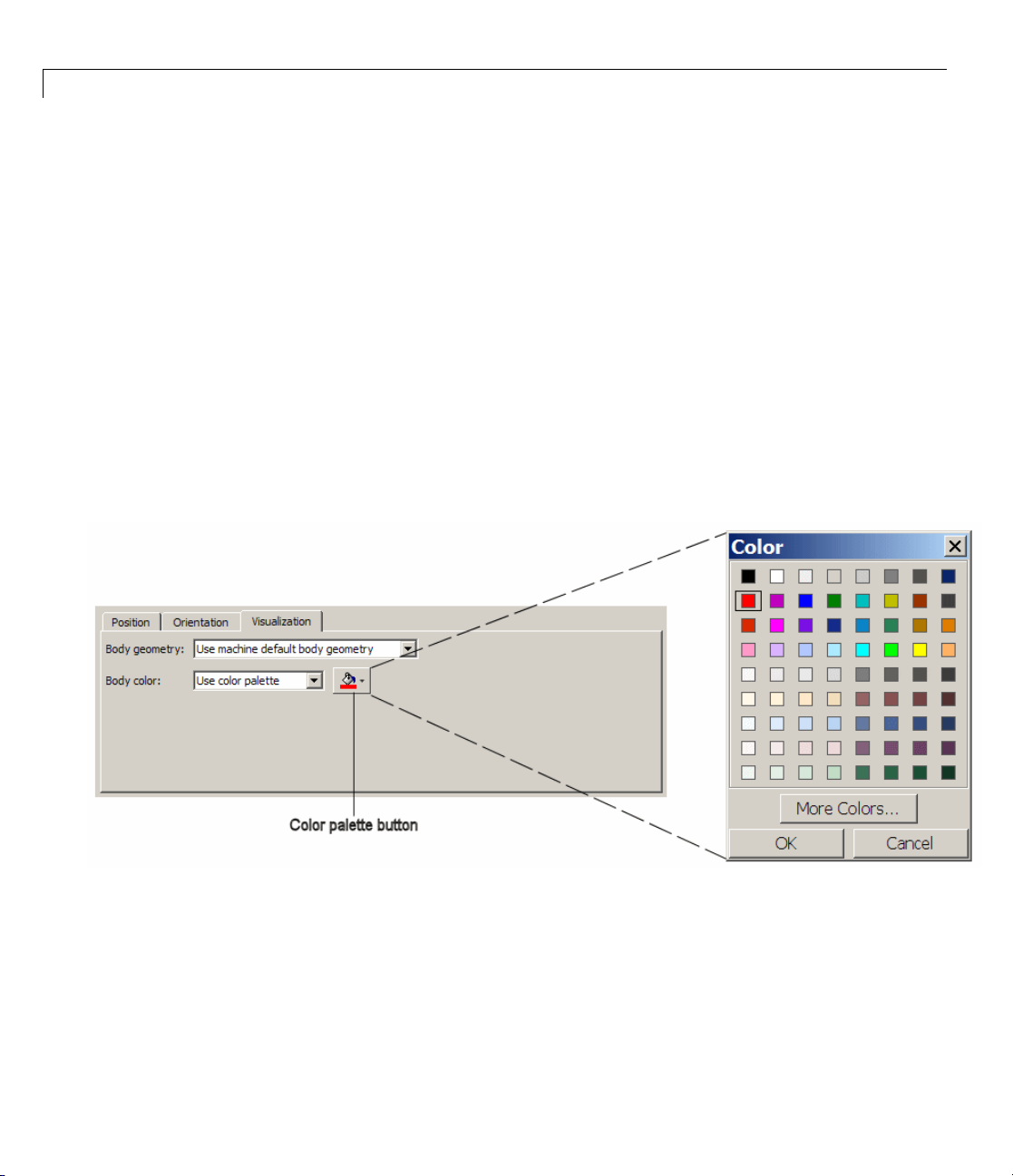
3 Custom izing Visualization and Animation
Changing the Color of an Individual Body
The initial default is for a Body to inherit its machine-wide body color. You
can override the initial default by specifying a different color for an individual
visualized body.
1 Open the Body block dialog and click its Visualization tab.
2 In the Body color pull-down menu, choose Use color palette.Thecolor
palette button appears.
3 Click the color palette button. The color palette opens.
4 Select a color from the palette and click OK.
5 To save the changes to the Body block and the model, click OK on the
Body dialog.
Body Dialog: Visualization Tab and Body Color Palette
3-6

Customizing Visualized Body Geometries
In this section...
“Choosing Custom Body Geometries” on page 3-7
“Switching Betw een Standard Body Geometries” on page 3-7
“About STL Body Graphics Files” on page 3-8
“Obtaining STL Body Graphics Files for Custom Body Geometries” on
page 3-9
“Switching Between Standard and Custom Body Geometries” on page 3-10
Choosing Custom Body Geometries
Using body mass and geom etry information from the Body block alone, the
SimMechanics visualization window allows you two choices of standard body
geometry, the convex hull and the equivalent ellipsoid.
Customizing Visualized Body Geometries
You also have the choice of a nonstandard body geometry specified by an
external graphics file.
Switching Between Standard Body Geometries
The SimMechanics initial default body geometry for visualized bodies is the
convex hull.
Changing the Default Geometry for All Bodies in a Model
You can change the initial default of convex hulls to equivalent ellipsoids
for all visualized bodies in a mo de l.
1 Open the Configuration Parameters dialog, then go to the SimMechanics
node.
2 In the Visualization area, select Equivalent ellipsoid from mass
properties
ick Apply or OK.
3 Cl
from th e Default body geometries pull-down menu.
3-7

3 Custom izing Visualization and Animation
Note You can override the model-wide default body geometry, both for a
whole machine and for individual bodies.
Changing the Default Geometr y for All Bodies in a Machine
The initial default is for a machine to inherit its model-wide body geometry.
You can override the initial default by specifying a different machine-wide
default geometry for all the bodies in one machine in your model.
1 Open that machine’s M achine Environment block dialog and click its
Visualization tab.
2 In the Default body geometries pull-down menu, choose a new
machine-wide default, either
Equivalent ellipsoid from mass prop erties.
3 Click Apply or OK.
Convex hull from body CS locations or
3-8
Note You can override the machine-wide default body geometry for any
individual body within the machine.
Changing the Geometry of an Individual Body
The initial default is for a Body to inherit its machine-wide body geometry.
You can override the initial default by specifying a different geometry for an
individual visualized body.
1 Open the Body block dialog and click its Visualization tab.
2 In the Body geometry pull-down menu, choose either Convex hull from
body CS locations
3 Click Apply or OK.
or Equivale nt ellipsoid from mass properties.
About STL Body Graphics Files
SimMechanics visualization supports the specification of body geometry (size
and shape) with stereolithographic (STL) files in either ASCII or binary

Customizing Visualized Body Geometries
format. Each body with a custom geometry requires one STL file to provide
this geometry.
Stereolithography specifies the three-dimensional surface geometry of a body
by linked triangles whose edges and vertices are oriented by the right-hand
rule. The orientation defines an “outside” and an “inside” of the surface. The
edges and vertices of the elementary triangles join to form a continuous
surface. A closed surface of such linked triangles approximates a body’s
smooth curved surface.
Stereo
hulls
syste
can sp
at ar
the B
Obt
Geo
You
lithographic triangles have some similarity to convex hulls . But convex
are directly and solely determined by the origins of the Body coordinate
ms. Convex hulls are not n ecessarily made up of triangles. An STL fil e
ecify an arbitrary number of elementary oriented triangles with vertices
bitrary points in space. These vertices have no necessary connection to
ody coordinate systems.
aining STL Body Graphics Files for Custom Body
metries
can obtain STL body geometry files from a number of sources.
3-9

3 Custom izing Visualization and Animation
• You can write a new STL file as a text file, following the STL standard.
• You can generate an STL file from many mechanica l design applications,
such as computer-aided design (CAD) platform s.
• The SimMechanics Link utility exports an STL file for each part in a CAD
assembly. The CAD platform must be linked to the SimMechanics Link
utility.
• You can reuse existing STL files, possibly with your own modifications. You
can obtain such STL files from SimMechanics demos, other applications,
and CAD-oriented Web sites.
Note Refer to the SimMechanics Link documentation for more information
about exported STL files.
Switching Between Standard and Custom Body Geometries
You can switch from the standard body geometries to a custom body geometry
by changing the Body block to reference a n external body geometry file. This
custom body geometry specification overrides the model- and machine-wide
defaults, but only for this body.
3-10
Requirements for External Body Geometry Files
The external body geometry file must be in STL format.
Caution In order for custom visualization to work, this STL file must be
either:
• On your MATLAB path.
• In your MATLAB present working folder.
• SpecifiedwithcompletepathintheBodydialog.
Otherwise, visualization reverts to the default body geometry.
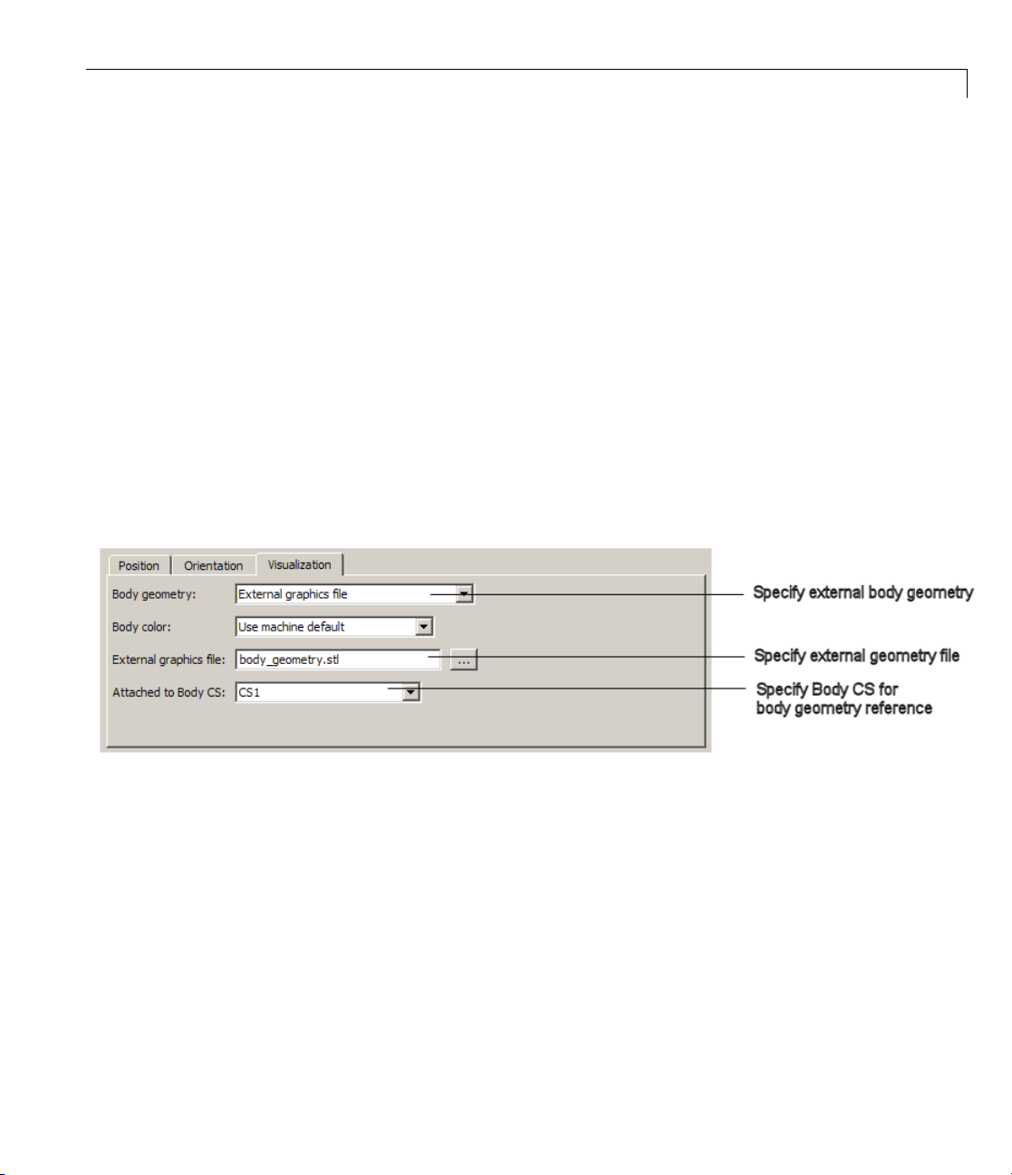
Customizing Visualized Body Geometries
Specifying an External Body Geometry File
1 Open the Body block dialog and click its Visualization tab.
2 In the Body geometry pull-down menu, choose External graphics file.
The External graphics file field and Attached to Body CS pull-menu
appear.
3 Enter the graphics file name and any necessary path in the field.
4 From the pull-down menu, choose which Body CS to attach the graphics
to. (The Body CSs are listed in the Body’s Position tab.) This Body CS
serves as the reference for the origin, coordinate axes, and units of the
body geometry.
5 Click Apply or OK.
Body Dialog: Visualization Tab and External Body Geometry Reference
Attached Body Coordinate System as Geometric Reference for the B
The external graphics file has no intrinsic geometric origin, orientation, or
units. The attached Body CS provides an origin, axis d irections (orientati o n),
and units of length to interpret the geometric information specified by the
external graphics file.
ody Geometry File
3-11

3 Custom izing Visualization and Animation
Tip If you need a body geometry origin, orientation, or system of units that is
not represented in your current list of Body coordinate systems, create a new
Body CS in the Position tab with the geometric features you want. You can
make this Body CS invisible on the Body block if you wish.
3-12

Visualizing with a Virtual Reality Client
In this section...
“About Virtual Worlds for Machines and Models” on page 3-13
“Creating Virtual Worlds for SimMechanics Models” on page 3-13
“Interfacing SimMechanics Models with Virtual Worlds” on page 3-18
“Reference” on page 3-27
About Virtual Worlds for Machines and Models
You can bypass SimMechanics visualization and create a mechanical
animation in a virtual world of your own design. You create a virtual world,
populate it with bodies represented as virtual objects using Virtual Reality
Modeling Language (VRML), then interface the virtual world with your
SimMechanics model. Creating your own virtual animation requires a new or
existing virtual world for your model and an interface between them.
Visualizing with a Virtual Reality Client
This section explains how to couple a separately created virtual world with a
SimMechanics model.
Building Virtual Worlds This section assumes that Simulink®3D
Animation™ software is installed on your system and that you are familiar
with it and with creating virtual worlds. Refer to the Simulink 3D Animation
documentation for full details on installing and using this toolbox.
We recommend you allocate generous central processor power, graphics card
speed, and memory for virtual reality visualization , especially for animation.
Creating Virtual Worlds for SimMechanics Models
The Simulink 3D Animation documentation and VRML books [1] explain how
to create virtual objects and assemble them into virtual worlds. A displayed
virtual world is called a virtual scene. The best way to become comfortable
moving around in a virtual world is to practice with a variety of movement
modes and viewpoints. This section highlights the requirements to m ake a
virtual world usable as a visualization for a SimMechanics model.
3-13

3 Custom izing Visualization and Animation
Editing Virtual Worlds and VRML Files
As you create a virtual world populated by virtual bodies, you must create
each component body, then plan and implement the geometry of the bodies’
initial s tate. Use a VRML authoring tool that can read VRML as a native
format to create and edit virtual reality
software includes a VRML authoring tool called V-Realm Builder
familiar with native VRML source code, you can use a plain text editor or
the MATLAB editor to edit the files.
Representing Bodies as Virtual Objects
You represent each body by a virtual object encoded in a .wrl file. You also
create a master
.wrl files, placing and orienting these bodies in the larger scene. You can
define a body’s position and orientation wit h respect to:
• The overall virtual world, corresponding to the SimMechanics coordinate
system World.
• Another body in the machine, corresponding to SimMechanics Body
coordinate systems.
.wrl files. Simulink 3D Animation
.wrl file to represent the virtual world that refers to body
®
.Ifyouare
3-14
You can nest body references to other bodies in VRML hierarchies, but you
must define at least one body’s position and orientation with respect to the
overall virtual world. Place and orient the bodies in their initial states,
corresponding with the initial state of the SimMechanics simulation.
Each body’s
node. Among Transform’s fields must be translation and rotation fields to
specify the body’s position and orientation in space. If a body is nested below
another body, its position and orientation are defined with respect to the
next body up the hierarchy.
Creating your own virtual world gives you great flexibility in representing
your machine:
• Youcandisplaybodiesinasmuchoraslittledetailasyouwant,with
shapes, colors, textures, etc., of your own choosing.
• You can include or omit bodies as desired.
.wrl file contains a hierarchical tree starting with the Transform

Visualizing with a Virtual Reality Client
• You can create a computer-aided design (CAD) assembly of your machine
andexportitintoVRMLfiles.
• If you only translate a body, you can omit the rotation field from its
Transform node.
• If you only rotate a body, you can omit the translation field from its
Transform node.
Example: Viewing Custom External VRML Files for the
Conveyor Loader
Thedemomodelmech_conveyor_vr is a modified version of the original
conveyor model
containing static geometries of the machine parts in their initial positions.
This e xample uses the V-Realm Builder editor to view the files.
1 In the matlabroot\toolbox\physmod\mech\mechdemos \ folder, open these
external VRML files with V-Realm Builder:
base.wrl, convmech.wrl, link1.wrl, link2.wrl, link3.wrl,
link4.wrl, pusher.wrl
mech_conveyor and comes with external VRML files
2 With the convmech.wrl world in focus, click the Test Mode button in
the V-Realm Builder toolbar and view the complete machine in the Main
3-15

3 Custom izing Visualization and Animation
view. Right-click in this window to configure the navigation. If the colors
seem washed out, disable the headlight.
3-16
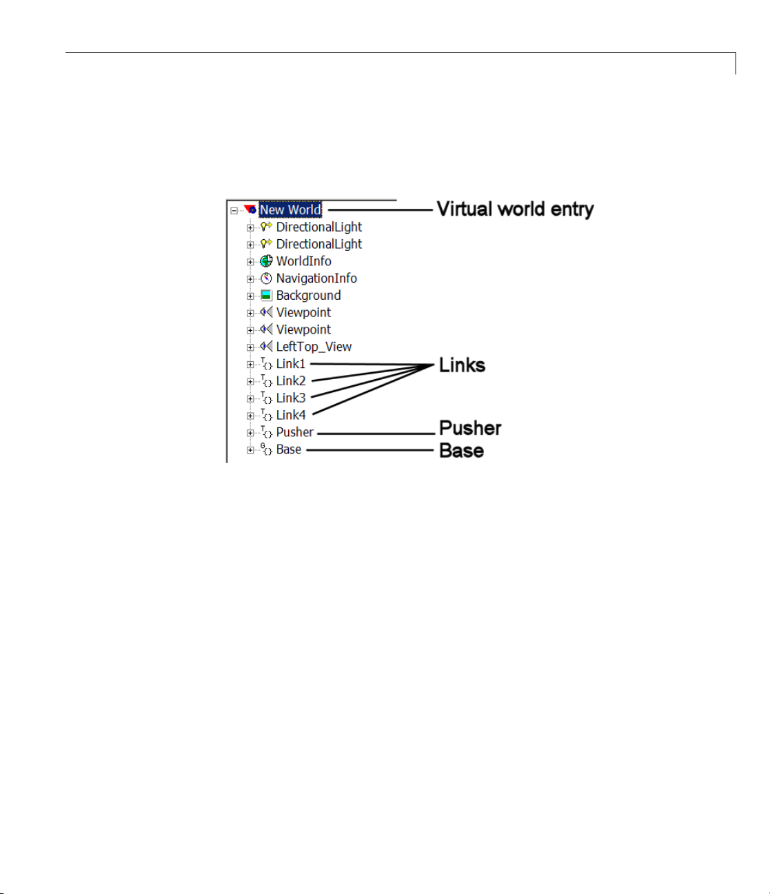
Visualizing with a Virtual Reality Client
3 OntheleftsideofyourVRMLeditor window, examine the node tree
of
convmech.wrl that refers to the six VRML files representing each
component body:
The hierarchy of body position and orientation references is flat in this
model. Each body is separately referenced to the top level of the hierarchy,
New World.
3-17

3 Custom izing Visualization and Animation
4 Expand one of the nodes. Each body node has, among others, rotation
and translation fields:
3-18
The exception is the base. Being grounded and immobile, it has neither
a translation nor a rotation field.
Interfacing SimMechanics Models with Virtual Worlds
To animate a body, you need to measure its motion in your SimMechanics
simulation and export that information to the virtual world. This requires
connecting Body Sensor blocks to the Bodies you want to animate in your
model, then creating an interface that animates the virtual bodies with
the body sensor motion signals. “Example: Interfacing the Conveyor
Loader Model a nd Virtual World” on page 3-21 applies these steps to the
mech_conveyor_vr demo.
Adding and Configuring Body Sensors
Refer to the SimMechanics User’s Guide for general information on how to use
Body Sensors. Connect the Body Sensors to Body coordinate systems (CSs)

Visualizing with a Virtual Reality Client
on the bodies whose motions you want to animate. The Body block reference
discusses how to create and configure Body CSs. You need to take these extra
steps to export the signals of a body sensor to your virtual world:
1 Make sure the Body Sensor’s Body CS reference origin and orientation
follow the body’s defining VRML hierarchy.
Example: You define a new Body CS on a body to connect the Body Sensor.
If you defined the VRML body’s position with respect to the center of
gravity (CG ) of a second, neighboring body in your VRML files, you should
set the Translated from origin of field of the new Body CS to the origin
of the CG CS of the second body.
2 In the Body Sensor dialog, select the [x;y;z]Positioncheck box if you
want to animate the body’s translational motion.
Select the [3 x 3] Rotation matrix check box if you want to animate the
body’s rotational motion.
3 Choose the coordinate system in which the body motions are measured in
the With respect to coordinate system pull-downmenu. Youcanpick
Absolute (World) or Local (Body CS). This coordinate system should
be the same as the coordinate system used to define the body’s position
and orientation in the VRML files.
A Simulink output port
> appears on the block for each o f the motio n signals.
The translational signal is a 3-vector of spatial coordinates, (x,y,z).The
rotational signal is a 9-vector, column-wise representation of the 3-by-3
orthogonal rotation matrix R, (R
11,R21
, R31, R12, ...).
Animating the Virtual World Bodies
Animating the virtual bodies requires interfacing the body sensor signals in
the SimM echanics model with the VRML translation and/or rotation fields in
the
.wrl files. Yo u accomplish this with the VR Sink block, which you can
find in the Simulink 3D Animation block library.
1 Enter vrlib at the command lin e. Drag a copy of the VR Sink block into
your model.
3-19

3 Custom izing Visualization and Animation
2 Open the VR Sink dialog box. (The figure Conveyor Loader Model: VR Sink
Dialog Box on page 3-26 displays an example of the dialog.)
3 In the Source file field in the World properties area, enter the name
of the VRML file that represents your model’s virtual world. This is the
file that refers to the other
yourmachine. IfthevirtualworldVRMLfileisnotinthesamefolderas
your model, enter the file’s path relative to the model.
Click Apply.IntheVRML Tree window, the node list of the virtual world
.wrl file appears.
4 Expandthetreeofeachcomponentbodyinthelisttoviewthatbody’s
check box list. Select the rotation and/or translation check boxes as
needed for each body. A Simulink input port
each of these selected check boxes.
.wrl files representing the component bodies of
> appears on the block icon for
The ports are labeled
field is named either rotation or translation.
node.field.Thenode is the nam e for the body. The
Converting Body Sensor Signals into VRML Format
You are now ready to connect the Body Sensor output signals to the VR Sink
block. But you might need to modify those signals for valid use in VRML.
• You can connect the translational motion signal line directly from the
output port of the Body Sen sor to the
VR Sink. The VRML node tree directly accepts translation motion as a
3-vector signal of rectangular coordinates (x,y,z).
Make sure that the translational motion signal refers to the same
coordinate system used to define the body’s positio n in the VRML files.
• You cannot directly connect the rotational motion signal line to the VR
Sink. The Body Sensor output represents orientation with a 3-by-3 rotation
matrix R, while VR ML accepts orientation represented as the axis-angle
4-vector form [ n θ ], where n = (n
rotation axis and θ is the rotation angle.
Open the SimMechanics U tilities library. For each rotational motion
signal, drag a Ro tationMatrix2VR block into your model. Connect the
rotation signal from the Body Sensor block to the RotationMatrix2VR
node.translation inputportonthe
, ny, nz) is a 3-vector representing the
x
3-20

Visualizing with a Virtual Reality Client
block. Then connect the latter block to the corresponding node.rotation
input port on VR Sink for that body. This block converts the 3-by-3 R
matrix signal into the 4-vector VRML form.
Close the VR Sink block dialog. Your SimMechanics model now animates
the virtual world.
Example: Interfacing the Conveyor Loader Model and Virtual World
In the mech_conveyor_vr demo model, open the Body Sensor1 block. The
block measures the translational and rotational motion of Link3 in the
conveyor:
Body Sensor1 block has two Simulink output signals.
The
3-21

3 Custom izing Visualization and Animation
The other Body Sensor blocks are similar, except for Body Sensor2, w hich
measures only the translational motion of the pusher. All the Body Sensors
measure body motions with respect to World, the frame in which the conveyor
base is at rest. Each motion signal represents the body’s displacement relative
to its initial position.
3-22

Visualizing with a Virtual Reality Client
The mech_conveyor_vr model contains a Simulink 3D Animation subsystem
interfacing to the model’s custom VRML files. The interface is routed through
the
mech_conveyor_vrlib custom library.
Conveyor Loader Model with Custom Virtual Reality Animation I nterface
3-23

3 Custom izing Visualization and Animation
Custom Virtual Reality Animation Interface Subsystem
3-24
1 Trace each body sensor signal. The signals are routed through pairs
of Simulink Goto blocks (in the model) and From blocks (in the custom
library).
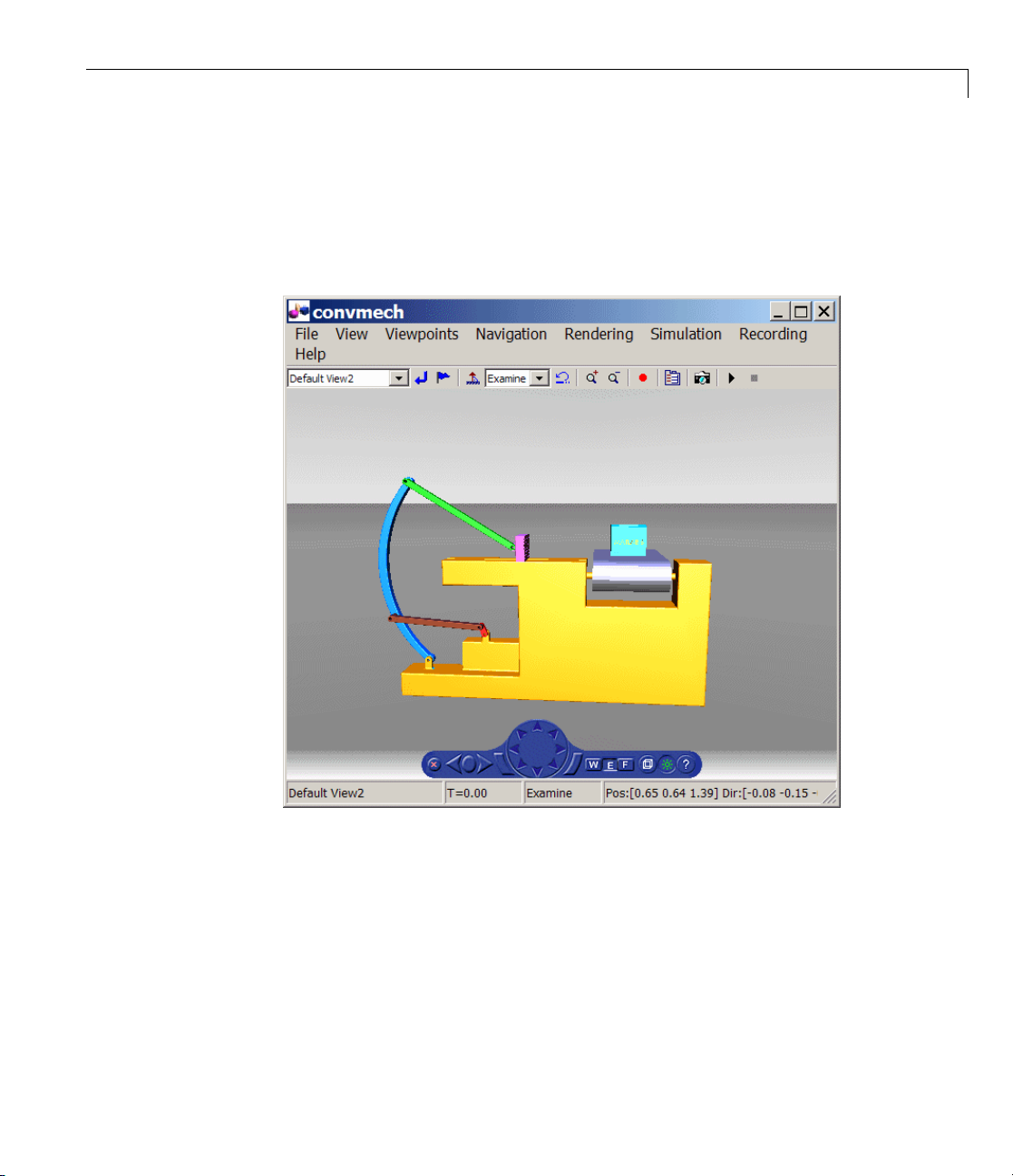
Visualizing with a Virtual Reality Client
2 Open the Simulink 3D Animation subsystem. The VR Sink block in the
custom library and the virtual scene viewer open, displaying the conveyor
machinescene. ThesceneissimilartothatvisibleintheVRMLeditor
(see “Example: Viewing Custom External VRML Files for the Conveyor
Loader” on page 3-15).
Conveyor Loader Model: Simulink®3D Animation™Viewer
3 From the menu bar of the virtual scene viewer, select Simulation,then
Block Parameters. The VR Sink block dialog opens.
The Source file is
convmech.wrl, the master file for this virtual world.
The VRML Tree on the right reproduces the nodetreevisibleintheVRML
editor for
convmech.wrl.
3-25
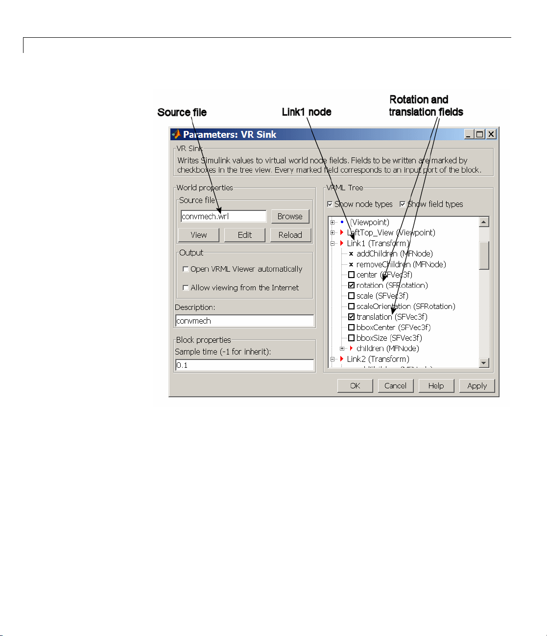
3 Custom izing Visualization and Animation
3-26
Conveyor Loader Model: VR Sink Dialog Box
4 Expand and scroll down the VRML trees. The trees for Link1, Link2,
Link3, Link4, and Pusher list the field inputs for accepting motion signals.
• The Link component bodies require both translational and rotational
motions. All the Links have actively selected check boxes for their
rotation and translation field inputs.
• The Pusher body requires only translational motion. Only the
translation fie ld check box is selected for the Pusher.

Visualizing with a Virtual Reality Client
Each of the nine Simulink input ports on the VR Sink block is named
node.field. The Base o f the conveyor does not move, so its node has no
motion input fields.
5 If you closed the Simulink 3D Animation viewer, you can reopen it from
the VR Sink dialog. Click View in the World properties / Source file
area of the dialog.
6 Close all the dialog boxes by clicking OK, leaving the viewer open.
7 Click the Start buttoninthemodelwindow.
As in the original
mech_conveyor demo, starting the model opens the
Reference Position slider bar that you can move from side to side. As you
do so, watch the pusher in the viewer move in parallel.
Reference
[1] Marrin, C., and B. Campbell, Teach Yourself VRML 2 in 21 Days,
Indianapolis, Indiana, Sams, 1997.
3-27

3 Custom izing Visualization and Animation
3-28

Importing Mechanical Models
Using SimMechanics software w ith computer-aided design (CAD) extends
your mechanical modeling and simulation capabilities, allowing you to create
SimMechanics models from CAD assemblies. This chapter covers what you
need to get started with CAD translation. It assumes some familiarity with
SimMechanics modeling, as e xplained in the SimMechanics Getting Started
Guide and SimMechanics User’s Guide.
4
• “Introducing Mechanical Import” on page 4-2
• “Generating New Models from Physical Modeling XM L” on pag e 4-6
• “Working with Generated Models” on page 4-12
• “Updating Generated Models Using Physical Modeling XML” on page 4-22
• “Controlling Model Update at the Block Level” on page 4-32
• “Troubleshooting Imported and Updated Models” on page 4-46

4 Importing Mechanical Models
Introducing Mechanical Import
In this section...
“About Mechanical Import and CAD Translation” on page 4-2
“Requirements for CAD E xport and Me chanical Import” on page 4-3
“Essential CAD Translation Steps” on page 4-4
About Mechanical Import and CAD Translation
SimMechanics software features an importer that lets you automatically
generate SimMechanics models from an XML file in Physical Modeling
format. This externally defined XML file specifies mechanical information —
bodies, degrees of freedom, and geometry — in a form that the SimMechanics
importer can use to construct a model representing that system.
The standard way to obtain such a Physical Modeling XM L is to generate it
by exporting a computer-aided aided (CAD ) assembly. CAD tools allow you to
model mechanical systems geometrically as collections of parts, or assemblies.
You use Simulink and SimMechanics block diagrams to represent control
systems composed of mechanical devices and simulate their dynamics. The
block diagram approach does not include full geometric information, nor do
CAD assemblies typically incorporate controllers or allow you to perform
dynamic simulations. With CAD translation, you can combine the power of
CAD and SimMechanics software.
4-2
The SimMechanics Link utility is the nece ssa ry intermediary that lets you
convert CAD assemblies into SimMechanics models. The intermediate step
between CAD assembly and SimMecha n ics model is exporting an XML file in
Physical Modeling format from the assembly. The export also automatically
creates STL files containing body geometry information that you need for
visualizing the bodies in the model.
The SimMechanics importer then converts this XML file into a mechanical
model, which refere n ces the STL files to visualize the bodies.
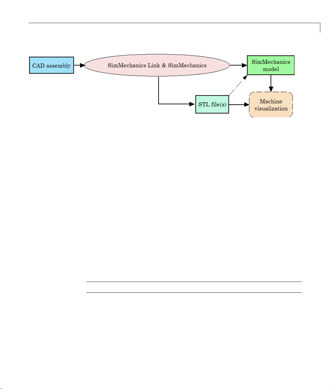
Complete Translation of CAD Assembly Into a Visualizable Model
Requirements for CAD Export and Mechanical Import
The full CAD translation is composed of two distinct steps, with different
requirements.
1 The first step is the e xport of the CAD assembly, which creates the Physical
Modeling XML file and one or more STL file(s).
Introducing Mechanical Import
2 The second step is the import of the Physical Modeling XML file and
generation of the SimMechanics model.
CAD Export Software Requirements
To export a CAD assembly into XML, you mu st first
1 Install your CAD platform or software application.
2 Install the SimMechanics Link utility and link it to your CAD platform.
The SimMechanics Link utility requires MATLAB only.
Note For CAD export, you do not need Simulink or SimMechanics software.
Setting Up SimMechanics Link Software. Learn more about and obtain
the SimMechanics Lin k utility at the MathWorks™ Web site.
4-3

4 Importing Mechanical Models
Physical Modeling XML Import Software Requirements
To import a Physical Modeling XML file and generate a model, you must have
installed Simulink and the Simscape™ and SimMechanics products.
Note For XML import, you do not need a CAD platform or the SimMechanics
Link utility.
Essential C AD Translation Steps
Converting a CAD assembly to a SimMechanics model requires two major
steps, exporting the CAD assembly into XML, then importing the XML t o
create a SimMechanics model.
Exporting an Assembly to XML
You export the assembly from the CAD platform into a Physical Mo deling
XML file that you can later use with the SimMechanics importer. See the
SimMechanics Link User’s Guide.
4-4
ting a CAD Assembly into a Physical Modeling XML File
Expor
Automatic Export of STL Files Representing CAD Part Geometries
When you export the CAD assembly into Physical Modeling XML, the
SimMechanics Link exporter also automatically creates an STL body
geometry file for each body represented as a CAD assembly part. You then
need these STL files for SimMechanics visualization, once you create your
SimMechanics model.

Introducing Mechanical Import
See “Referencing STL Body Geometry Files for SimMechanics Model
Visualization” on page 4-5.
Importing the XML and Generating a Model
To complete the CAD translation, you convert the Physical Modeling XML
file into a SimMechanics model. See “Generating New Models from Physical
Modeling XML” on page 4-6.
Importing a Physical Modeling XML File into a Model
Referencing STL Body Geometry Files for SimMechanics Model
Visualization
Once you have imported the Physical Modeling XML to create a SimMechanics
model, you can visualize the bodies in the model. The generated SimMechanics
model automatically references the necessary ST L body geometry files, one for
each body, to visualize the bodies with their original CAD assembly shapes.
4-5

4 Importing Mechanical Models
Generating New Models from Physical Modeling XML
In this section...
“About Generated SimMechanics Models Based on CAD” on page 4-6
“Generating a New Model from a Physical Modeling XML File” on page 4-7
“Controlling New Model Import with Nondefault Options” on page 4-8
About Generated SimMechanics Models Based on CAD
Note For complete information on exporting Physical Modeling XML, see
the SimMechanics Link User’s Guide.
A computer-aided design (CAD) assembly can contain enough part and
constraint information that you can generate a SimMechanics model
consisting of Body and Joint blocks representing the assembly. Once you
have exported a CAD assembly into a Physical Modeling XML file, you
can generate a SimMechanics block diagram model from this file. A new
generated model consists of a single SimMechanics machine, corresponding to
an assembly with a sing le root.
4-6
This section shows you how to import the XML file into a SimMechanics
model using the command
mech_import, which constructs the model.
Requirements for G enerating Models by Importing Physical
Modeling XML
This section assumes that you have the SimMechanics product installed
locally or remotely, and that you have:
• The XML file representing a CAD assembly
• Optionally, STL body geometry files associated with the CAD parts

Generating New Models from Physical Modeling XML
To generate the SimMechanics model, you do not need the CAD platform or
assembly from which the XML file was exported. You also do not need the
SimMechanics Link utility.
Generating a New Model from a Physical Modeling XML File
You generate the CAD-based SimMechanics model using the mech_import
command or dialog.
Using the Command Line
To start the model generation from a hypothetical XML file called
cad_assembly.xml,enter
mech_import('cad_assembly.xml')
at the command line. A progress bar appears and is updated as the model
is imported.
A Simulink model window opens. The model is populated by Bodies
and Joints corresponding to the assembly parts and constraints saved in
cad_assembly.xml. The name of the generated model is the name of the
original assembly file, regardless of the name chosen for the XML file.
Using the Import Dialog
You can also select a Physical Modeling XML file and generate a model from
it through the Import Physical Modeling XML dialog. Open it by entering
mech_import at the command line with no arguments. See the mech_import
command reference for complete information about the import dialog. After
completing your settings, click OK to start the import.
4-7
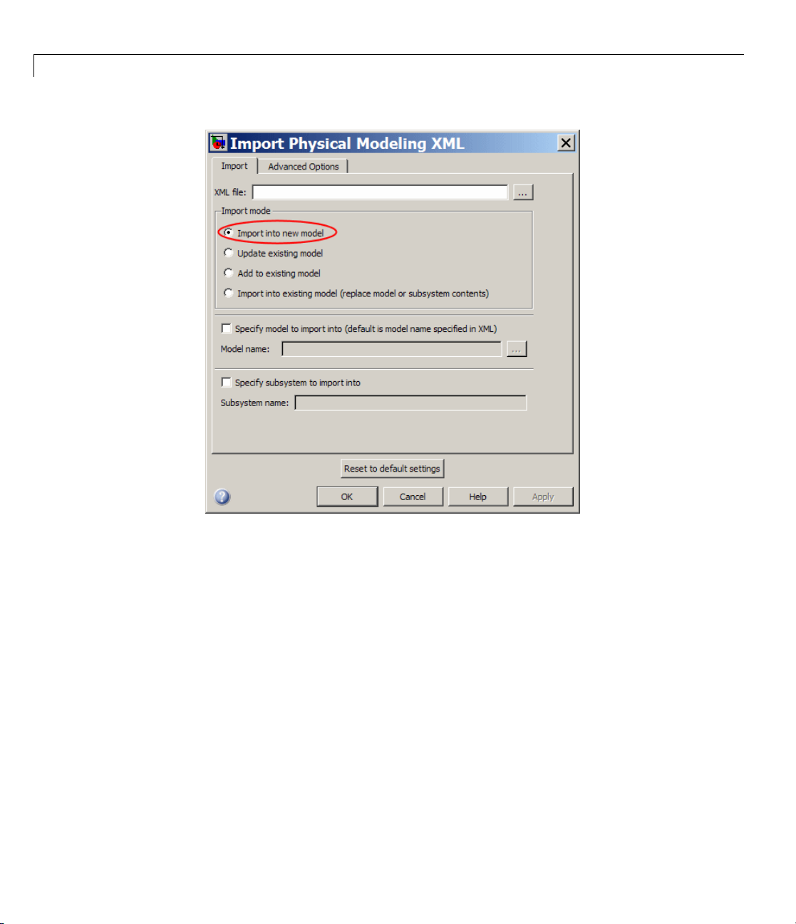
4 Importing Mechanical Models
4-8
Controlling New Model Import with Non default Options
You have several options for changing the default import behavior of
mech_import and the Import Physical Modeling XML dialog box. For more
information, see “Nondefault Features in Generated Models” on page 4-15.
Customizing the Generated Model Name
You can specify the name of the generated model in the mech_import
command or the import dialog. The default is to accept the assembly name
specified in the XML file.
For example, an XML file called
the assembly name as CAD_A ssembly. Generating a model from this XML
cad_assembly.xml could internally specify
 Loading...