

Page 1

®
Real-Time Worksho
p
Getting Started Guide
Embedded Coder™ 5
Page 2

How to Contact The MathWorks
www.mathworks.
comp.soft-sys.matlab Newsgroup
www.mathworks.com/contact_TS.html Technical Support
suggest@mathworks.com Product enhancem ent suggestions
bugs@mathwo
doc@mathworks.com Documentation error reports
service@mathworks.com Order status, license renewals, passcodes
info@mathwo
com
rks.com
rks.com
Web
Bug reports
Sales, prici
ng, and general information
508-647-7000 (Phone)
508-647-7001 (Fax)
The MathWorks, Inc.
3 Apple Hill Drive
Natick, MA 01760-2098
For contact information about worldwide offices, see the MathWorks Web site.
®
Real-Time Workshop
© COPYRIGHT 2007–20 10 by The MathWorks, Inc.
The software described in this document is furnished under a license agreement. The software may be used
or copied only under the terms of the license agreement. No part of this manual may be photocopied or
reproduced in any form without prior written consent from The MathW orks, Inc.
FEDERAL ACQUISITION: This provision applies to all acquisitions of the Program and Documentation
by, for, or through the federal government of the United States. By accepting delivery of the Program
or Documentation, the government hereby agrees that this software or documentation qualifies as
commercial computer software or commercial computer software documentation as such terms are used
or defined in FAR 12.212, DFARS Part 227.72, and DFARS 252.227-7014. Accordingly, the terms and
conditions of this Agreement and only those rights specified in this Agreement, shall pertain to and govern
theuse,modification,reproduction,release,performance,display,anddisclosureoftheProgramand
Documentation by the federal government (or other entity acquiring for or through the federal government)
and shall supersede any conflicting contractual terms or conditions. If this License fails to meet the
government’s needs or is inconsistent in any respect with federal procurement law, the government agrees
to return the Program and Docu mentation, unused, to The MathWorks, Inc.
Trademarks
MATLAB and Simulink are registered trademarks of The MathWorks, Inc. See
www.mathworks.com/trademarks for a list of additional trademarks. Other product or brand
names may be trademarks or registered trademarks of their respective holders.
Patents
The MathWorks products are protected by one or more U.S. patents. Please see
www.mathworks.com/patents for more information.
Embedded Coder™ Getting Started Guide
Page 3

Revision History
September 2007 First printing New for Version 5.0 (Release 2007b)
March 2008 Online only Revised for Version 5.1 (Release 2008a)
October 2008 Online only Revised for Version 5.2 (Release 2008b)
March 2009 Online only Revised for Version 5.3 (Release 2009a)
September 2009 Online only Revised for Version 5.4 (Release 2009b)
March 2010 Online only Revised for Version 5.5 (Release 2010a)
Page 4

Page 5

Contents
Getting Started with Real-Time Workshop
1
What You Need t
Embedded C ode
What You Can A
Technology
How the Tech
Process
Tools for A
Target Env
Applicati
How You Ca
System D
What Is t
Types of
Types of
Valida
Embedded Coder Software
oKnowtoUseReal-TimeWorkshop
r
................................
ccomplish Using Real-Time Workshop
..................................... 1-3
nology Can Fit Into Your Development
......................................... 1-6
lgorithm Development
ironments
ons
......................................
n Apply the Technology to the V-Model for
evelopment
he V-Model?
Simulation and Prototyping
In-the-Loop Testing for Verification and
tion
.....................................
..............................
.............................
..............................
....................
.................
®
1-10
1-14
1-16
1-16
1-18
1-19
®
1-2
1-6
2
Learn
ng the Tutorials
Usi
roduction
Int
requisites
Pre
ird-Party Software
Th
tting Up the Tutorial Files
Se
ingandUsingReal-TimeWorkshop
......................................
.....................................
Embed
ded Coder Software
................................
..............................
........................
2-2
2-2
2-3
22-
®
3
4
v
Page 6

Understanding the Demo M odel ..................... 2-5
Introduction
Understanding the Functional Design of the Model
Viewing the Top Model
Viewing Subsystems
Understanding the Simulation Testing Environment
Running the Simulation Tests
Setting the Configuration Options for Code Generation
Saving the Configuration Parameters as a MATLAB
Function
Generating Code for the Model
Examining the Generated Code
Topics for Further Study
...................................... 2-5
...... 2-6
............................. 2-6
............................... 2-7
.... 2-8
....................... 2-12
.. 2-13
....................................... 2-24
...................... 2-24
...................... 2-25
........................... 2-27
Configuring the Data Interface
Introduction
Declaring Data
Using Data Objects in Simulink Models and Stateflow
Charts
Adding New Data Objects
Configuring Data Objects
Controlling File Placement of Parameter Data
Enabling Data Objects in Generated Code
Effects of Simulation on Data Typing
Viewing Data Objects in Generated Code
Managing Data
Topics for Further Study
Partitioning Functions in the Generated Code
Introduction
About Atomic and Virtual Subsystems
Viewing Changes in the Model Architecture
Controlling Function Location and File Placement in
Generated Code
Understanding Reentrant Code
Using a Mask to Pass Parameters into a Library
Subsystem
Generating Code from an Atomic Subsystem
Generating Code: Full Model vs. Exported Functions
Effect of Execution Order on Simulation Results
Topics for Further Study
...................................... 2-28
................................... 2-28
........................................ 2-31
........................... 2-34
........................... 2-35
................................... 2-42
........................... 2-42
...................................... 2-43
................................. 2-45
..................................... 2-47
........................... 2-53
..................... 2-28
.......... 2-35
............. 2-36
................. 2-37
.............. 2-39
................ 2-43
............ 2-44
...................... 2-46
........... 2-48
....... 2-43
.... 2-49
........ 2-51
vi Contents
Page 7

Calling External C Functions from the Model and
Generated Code
Introduction
Including Preexisting C Functions in a Simulink Model
Creating a Block That Calls a C Function
Validating the External Code in the Simulink
Environment
Validating the C Code as Part of the Simulink Model
Calling the C Function from the Generated Code
Topics for Further Study
Integrating the Generated Code into the External
Environment
Introduction
Building and Collecting the Required Data and Files
Integrating the Generated Code into an Existing
System
About the Integration Environment
Matching the System Interfaces
Matching Function-Call Interfaces
Building a Project in the Eclipse Environment
Topics for Further Study
........................................ 2-62
................................. 2-54
...................................... 2-54
.............. 2-55
................................... 2-56
........ 2-59
........................... 2-60
.................................... 2-61
...................................... 2-61
.................. 2-62
...................... 2-64
................... 2-66
.......... 2-67
........................... 2-68
.. 2-54
.... 2-58
.... 2-61
Testing the Generated Code
Introduction
Methods for Validating Generated Code
Reusing Test Data: Test Vector Import/Export
Testing via Software-in-the-Loop (S-Functions)
Configuring the System for Testing via Test Vector
Import/Export
Testing with Test Vector Import/Export Using the Eclipse
Environment
Testing via Processor-in-the-Loop (PIL)
Evaluating the Generated Code
Introduction
Evaluating Code
About the Compiler Used
Viewing the Code Metrics
About the Build Option Configurations
Configuration 1: Reusable Functions, Data Type Double
Configuration 2: Reusable Functions, Data Type Single
...................................... 2-69
.................................. 2-74
................................... 2-76
...................................... 2-78
.................................. 2-78
........................ 2-69
............... 2-69
......... 2-71
......... 2-72
............... 2-77
..................... 2-78
........................... 2-79
........................... 2-79
................ 2-79
.. 2-80
.. 2-81
vii
Page 8

Configuration 3: N onreusable Functions, Data Type
Single
......................................... 2-82
Installing and Using an IDE for the Integration
and Testing Tutorials (Optional)
A
Installing the Eclipse IDE and Cygwin Debugger ..... A-2
Installing the Eclipse IDE
Installing the Cygwin Debugge r
.......................... A-2
..................... A-3
Integrating and Testing Code with the Eclipse IDE
Introducing Eclipse
Defining a New C Project
Configuring the Debugger
Starting the Debugger
Setting the Cygwin Path
What the Eclipse Debugger Can Do
................................ A-4
........................... A-5
.......................... A-6
............................. A-7
............................ A-7
................... A-8
... A-4
viii Contents
Page 9

Getting Started with Real-Time Workshop Embedded Coder Software
• “What You Need to Know to Use Real-Time Workshop®Embedded Coder”
on page 1-2
• “What You Can Accomplish Using Real-Time Workshop Technology” on
page 1-3
1
• “How the Technology Can Fit Into Your Development Process” on page 1-6
• “How You Can Apply the Technology to the V-Model for System
Development” on page 1-16
Page 10

1 Getting Started with Real-Time Workshop
®
Embedded Coder™ Software
WhatYouNeedtoKnowtoUseReal-TimeWorkshop Embedded Coder
Before you use t
should be famil
he Real-Time Workshop
iar with
• Using the Simu
machines as bl
interpretin
• Using Real-T
programs fr
• High-level
g output in the MATLAB
ime Workshop
om Simulink models
programming language concepts applied to embedded, real-time
®
link
and Stateflow®software to create models or state
ock diagrams, running such simulations in Simulink, and
®
software to generate code and build executable
®
Embedded Coder™ software, you
®
workspace
systems
If you have
• The tutor
tutorial
generati
• “Laying
the Real
overvie
Real-T
If you a
to map c
rns that include Simulink blocks, Stateflow charts, and Embedded
patte
MATLA
Web si
not done so, you should read:
ials in the Real-Time Workshop Getting Started Guide.The
s provide hands-on experience in configuring models for code
on and g enerating code.
Out the Model Architecture” and “Scheduling Considerations” in
-Time Workshop documentation. These sections give a general
w of the architecture and execution of programs generated by
ime Workshop software.
re familiar with C language constructs and want to learn about how
ommonly used C constructs to code generated from model design
®
B
functions, see Technical Solution 1-6AWSQ9 on the M athW orks™
te.
1-2
Page 11

What You Can Accomplish Using Real-Time Workshop®Technology
What You Can Accomplish Using Real-Time Workshop Technology
Real-Time Work
executables fo
environment o
subset. You ca
functions tha
generated so
the function
code executi
product, yo
match to mod
of accuracy
integrate
engines. I
Real-Time
You apply
Workshop
Real-Tim
• Generat
(fixed-
• Use the
includ
hardwa
r algorithms that you model graphically in the Simulink
r programmatically with the Embedded MATLAB language
t are useful for real-time or embedded applications. The
urce code and executables for floating-point algorithms match
al behavior of Simulink simulations and Embedded MATLAB
on to high degrees of fidelity. Using the S i mulink
ucangeneratefixed-pointcodethat provides a bit-wise accurate
el simulation results. Such broad support and high degrees
are possible because Real-Time Workshop technology is tightly
d with the MATLAB and Simulink execution and simulation
n fact, the built-in accelerated simulation modes in Simulink use
Workshop technology.
Real-Time Workshop technology explicitly with the Real-Ti m e
and Real-Time Workshop Embedded Coder products. Using the
e Workshop product, you can
e source code and executables for discrete-time, continuous-time
step),andhybridsystemsmodeledinSimulink
generated code for real-time and non-real-time applications,
ing simulation acceleration, rapid prototyping, and
re-in-the-loop (HIL) testing
shop technology generates C or C++ source code and
n generate code for any Simulink blocks and MATLAB
®
Fixed Point™
• Tune a
analy
the MA
• Gene
mode
• Prod
by T
The
Wor
nd monitor the generated code by using Simulink blocks and built-in
sis capabilities, or run and interact with the code completely outside
TLAB and Simulink environment
rate code for finite state machines modeled in Stateflow event-based
ling software, using the optional Stateflow
uce source code for many Simulink products and blocksets provided
he MathWorks™ and third-party vendors.
Real-Time Workshop Embedded Coder product extends the Real-Time
kshop product with features that are important for embedded software
®
Coder™ product
1-3
Page 12

1 Getting Started with Real-Time Workshop
development. Using the Real-Time Workshop Embedded Coder add-on
product, you gain access to all aspects of Real-Time Workshop technology
and can generate code that has the clarity and efficiency of professional
handwritten code. For example, you can
• Generate code that is compact and fast, which is essential f or real-time
simulators, on-target rapid prototyping boards, microprocessors used in
mass production, and embedded systems
• Customize the appearance of the generated code
• Optimize the generated code for a specific target environment
• Integrate existing (legacy) applications, functions, and data
• Enable tracin g, reporting, and t estin g options that facilitate code
verification activities
The following table compares typical applications and key capabilities for
these two code generation products.
®
Embedded Coder™ Software
Product Typical Applications Key Capabilities
Real-Time Workshop
Simulation acceleration
Simulink model encryption
Rapid prototyping
HIL testing
Generate code for discrete-time,
continuous-time (fixed-step),
andhybridsystemsmodeledin
Simulink
Tune and monitor the execution of
generated code by using Simulink
blocks and built-in analysis
capabilities or by running and
interacting with the code outside
the MATLAB and Simulink
environment
Generate code for finite state
machines modeled in Stateflow
event-based modeling software,
using the optional Stateflow Coder
product
1-4
Page 13

What You Can Accomplish Using Real-Time Workshop®Technology
Product Typical Applications Key Capabilities
Generate code for m any
MathWorks and third-party
Simulink products and blocksets
Integrate existing applications,
functions, and data
Real-Time Workshop
Embedded Coder
All applications listed for the
Real-Time Workshop product
Embedded systems
On-target rapid prototyping
boards
Microprocessors used in mass
production
All capabilities listed for the
Real-Time Workshop product
Generate code that has the clarity
and efficiency of professional
handwritten code
Customize the appearance and
performance of the code for specific
target environments
Enable tracing, reporting, and
testing options that facilitate code
verification activities
1-5
Page 14

1 Getting Started with Real-Time Workshop
®
Embedded Coder™ Software
How the Technology Can Fit Into Your Development Process
In this section...
“Tools for Algorithm Development” on page 1-6
“Target Environments” on page 1-10
“Applications” on page 1-14
Tools for Al
You can use
source cod
• With MATL
• As Simuli
• With MAT
The Embe
and func
dynami
large m
eventWorks
MathW
If you
to ma
patt
MATL
Web
The
Rea
tions for floating-point and fixed-point math. Simulink support for
c system simulation, conditional execution of system semantics, and
odel hierarchies provides an enviro n ment for modeling periodic and
driven algorithms commonly found in embedded systems. Real-Time
hop technology generates code for most Simulink blocks and many
orks products.
are familiar with C language constructs and want to learn about how
p commonly used C constructs to code generated from model design
erns that include Simulink blocks, Stateflow charts, and Embedded
AB functions, see Technical Solution 1-6AWSQ9 on the MathWorks
site.
following table lists products that the Real-Time Workshop a nd
l-Time Workshop Embedded Coder softwa re support.
gorithm Development
Real-Time Workshop technology to generate standalone C or C++
e for algorithms that you develop the following ways:
AB code, usin g the Embedded MATLAB language s ub set
nk models
LAB code that you incorporate into Simulink models
dded MATLAB language subset supports MATLAB operators
1-6
Page 15

How the Technology Can Fit Into Your Development Process
Products Supported by Real-Time
Notes
Workshop and Real-Time Workshop
Embedded Coder
Aerospace Blockset™
Communications Blockset™
Control System T oo lbox™
Embedded IDE Link™
Fuzzy Logic Toolbox™
Gauges Blockset™
—
—
—
—
—
—
MATLAB Details: Supports Embedded MATLAB
Model-Based Calibration Toolbox™
Model Predictive Control Toolbox™
PolySpace®Model Link™ SL
Real-Time Windows Target™
—
—
Not supported by Real-Time Workshop
—
Signal Processing Blockset™ Details: “Simulink Block D ata Type Support
for Signal Processing Blockset” Table (enter the
MATLAB
showsignalblockdatatypetable
command)
SimDriveline™
SimElectronics
SimHydraulics
SimMechanics™
®
®
—
—
—
—
SimPowerSystems™
Not supported by Real-Time Workshop
Embedded Coder
Simscape™
—
Simulink Details: “Simul in k Built-In Blocks T hat
Support Code Generation” Table in the
Real-Time Workshop documentation
Simulink Fixed Point
Simulink®3D Animation™
—
—
1-7
Page 16

1 Getting Started with Real-Time Workshop
®
Embedded Coder™ Software
Products Supported by Real-Time
Workshop and Real-Time Workshop
Embedded Coder
Simulink®Design Optimization™
Simulink®Report Generator™
Simulink®Verification and Validation™
Stateflow and Stateflow Coder
System Identification Toolbox™
Target Support Package™
Vehicle Network Toolbox™
Video and Image Processing Blockset™
xPC Target™
xPC Target Embedde d Option™
Notes
—
—
—
—
Exceptions:
• Nonlinear IDNLGREY Model, IDDATA
Source, IDDATA Sink, and estimator blocks
• Nonlinear ARX models that contain custom
regressors
•
neuralnet nonlinearities
customnet nonlinearities
•
—
Exception: CAN Configuration, CAN Receive,
and CAN Transmit blocks in the CAN
Communication library
—
—
—
1-8
Use of both Embedded MATLAB code and Simulink models is typical for
Model-Based Design projects where you start developing an algorithm
through research and development or advanced production, using MATLAB,
and then use Simulink for system deploym ent and verification. Benefits of
this approach include:
• Richer system simulation environment
• Ability to verify the Embedded MATLAB code
Page 17

How the Technology Can Fit Into Your Development Process
• Real-Time Workshop a nd Real-Time Workshop Embedded Coder C/C++
code generation for the model and embedded MATLAB code
Thefollowingtablesummarizeshowtogenerate C or C++ code for each of the
three approaches and identifies where you can find more information.
If you develop
Yougeneratecodeby...
algorithms using...
Embedded MATLAB
language subset
Entering the Real-Time
Workshop function emlc in the
MATLAB Command Window.
Simulink Configuring and initiating code
generation for your model or
subsystem with the Simulink
Configuration Parameters
dialog.
Embedded MATLAB
language subset and
Simulink
Including Embedded MATLAB
code in Simulink models or
subsystems by using the
Embedded MATLAB Function
block.
To use this block, you can do
one of the following:
• Copy your code into the block.
• Call your code from the
block by referencing the
appropriate files on the
MATLAB path.
For more information, see...
“Working with the Embedded
MATLAB Subset”
“Converting MATLAB Code to
C/C++ Code”
“Workflow for Developing
Applications Using Real-Time
Workshop Software” in Getting
Started with Real-Time
Workshop
“Working with the Embedded
MATLAB Subset” in
the Embedded MATLAB
documentation
The following figure shows the three design and deployment environment
options. Although not shown in the figure, other products that support code
generation, such as Stateflow software, are available.
1-9
Page 18

1 Getting Started with Real-Time Workshop
®
Embedded Coder™ Software
Other MATLAB
code
MATLAB
®
Embedded MATLAB
language subset
™
Real-Time Workshop
C or C++
Compiler or
IDE toolchain
Executable
(runs in target environment)
Simulink
Embedded MATLAB
Function block
®
technology
®
™
Other Simulink
blocks
1-10
Targ et Environments
In addition to generating source code for a model or subsystem, Real-Time
Workshop technology generates make or project files you need to build an
executable for a specific target environment. The generated make or project
files are optional. That is, if you prefer, you can build an executable for the
generated source files by using an existing target build environment, such
as a third-party integrated development environment (IDE). Applications
of code generated with Real-T ime Workshop technology range from calling
a few exported C or C++ functions on a host com puter to generating a
complete executable using a custom build process, for custom hardware, in an
environment completely separate from the host computer running MATLAB
and Simulink.
Page 19

How the Technology Can Fit Into Your Development Process
Real-Time Workshop technology provides built-in system target files that
generate, build, and execute code for specific target environments. These
system target files offer varying degrees of s upport for interacting with the
generated code to log data, tune parameters, and experiment with or w ithout
Simulink as the external interface to your generated code.
Before you select a system target file, you need to identify the target
environment on which you expect to execute your generated code. The three
most common target environments include:
Target
Environment
Host computer
Real-time
simulator
Description
The same computer that runs MATLAB and Simulink. Typically, a host
computer is a PC or UNIX
operating system, such as Microsoft
1
®
environment that uses a non-real-time
®
Windows®or Linux
2
®
.Non-real-time
(general purpose) operating systems are nondeterministic. For example,
they might suspend code execution to run an operating system service
and then, after providing the service, continue code execution. Thus, the
executable for your generated code might run faster or slower than the
sample rates you specified in your model.
A different computer than the host computer. A real-time simulator can
be a PC or UNIX environment that use s a real-time operating system
(RTOS), such as:
• xPC Target system
• Areal-timeLinuxsystem
• A Versa Module Eurocard (VME) chassis with Pow erP C
running a commercial R TO S, such as VxWorks
®
from Wind River
®
processors
®
Systems
The generated code runs in real time and behaves deterministically.
Although, the exact nature of execution varies based on the particular
behavior of th e system hardware and RTOS.
1. UNI
countries.
2. Linux
®
is a registered trademark of The Open Group in the Uni ted States a nd other
X
®
is a registered trademark of Linus Torvalds.
1-11
Page 20

1 Getting Started with Real-Time Workshop
®
Embedded Coder™ Software
Target
Environment
Embedded
microprocessor
Description
Typically, a real-time simulator connects to a host computer for data
logging, interactive parameter tuning, and Monte Carlo batch execution
studies.
A computer that you eventually disconnect from a host computer a nd
run standalone as part of an electronics-based product. Embedded
microprocessors range in price and performance, from high-end digital
signal processors (DSPs) used to process communication signals to
inexpensive 8-bit fixed-point microcontrollers used in mass production (for
example, electronic parts produced in the millions of units). Embedded
microprocessors can:
• Use a full-featured RTOS
• Be driven by basic interrupts
• Use rate monotonic scheduling provided with Real-Time Workshop
technology
A target environment can:
• Have single- or multiple-core CPUs
1-12
• Be standalone or communicate as part of a computer network
In addition, you can deploy different parts of a Simulink model on different
target environments. For example, it is common to separate the component
(algorithm or controller) portion of a model from the environment (or plant).
Using Simulink to model an entire system (plant and controller) is often
referred to as closed-loop simulation and can provide ma n y benefits such as
early verification of component correctness.
The following figure shows example target environments for code generated
for a model.
Page 21

System model
How the Technology Can Fit Into Your Development Process
Algorithm model
Code
generation
Host
executable
Host computer(s)
Code
generation
Embedded
microprocessor
Environment model
Code
generation
Real-time
simulator
1-13
Page 22

1 Getting Started with Real-Time Workshop
Applications
The following ta
technology in th
®
Embedded Coder™ Software
ble lists several ways you can apply Real-Time Workshop
e contex t of the different target environments.
Application
Host Computer
Accelerated simulation You apply techniques to speed up the execution of model
Rapid simu
System simulation
Model encryption
Real
Rapid prototyping You generate, deploy, and tune code on a real-time
lation
-Time Simulator
Description
simulation in the context of the MATLAB and Simulink
environment. Accelerated simulations are especially
useful when run time is long compared to the time
associated with compilation and checking whether the
target is up to date.
You execute code generated for a model in non-real time
on the host computer, but outside the context of the
MATLAB and Simulink environment.
You inte
provide
for buil
shared
You gen
model
anoth
simulator connected to the system hardware (for
example, physical plant or vehicle) being controlled.
This design step is also crucial for validating whether a
component can adequately control the physical system.
grate components into a larger system. You
generated source code and related dependencies
ding in another environment or a host-based
library to which other code can dynamically link.
erate a Simulink shareable object library for a
or subsystem for use by a third-party vendor in
er Simulink simulation environment.
System simulation
1-14
You integrate generated source code and dependencies
for components into a larger system that is built in
another environment. You can use shared library files to
encrypt components for intellectual property protection.
Page 23

How the Technology Can Fit Into Your Development Process
Application
Description
On-target rapid prototyping You generate code for a detailed design that you can
runinrealtimeonanembeddedmicroprocessorwhile
tuning parameters and monitoring real-time data. This
design step allows you to assess, interact with, and
optimize code, using embedded compilers and hardware.
Embedded Microprocessor
Production code generation
From a model, you generate code that is optimized for
speed, memory usage, simplicity, and if necessary,
compliance with industry sta n dards and g uidelines.
Software-in-the-loop (SIL) testing
You execute generated code with your plant model
within Simulink to verify success ful conversion of
the model to code. You might change the code to
emulate target word size behavior and verify numerical
results expected when the code runs on an embedded
microprocessor, or use actual target word sizes and just
test production code behavior.
Processor-in-the-loop (PIL) testing
You test an object code component with a plant
or environment model in an open- or closed-loop
simulation to verify successful model-to-code conversion,
cross-compilation, and software integration.
Hardware-in-the-loop (HIL) testing You verify an embedded system or embedded computing
unit (ECU), using a real-time target environment.
1-15
Page 24

1 Getting Started with Real-Time Workshop
®
Embedded Coder™ Software
How You Can Apply the Technology to the V-Model for
System Development
In this section...
“What Is the V-Model?” on page 1-16
“Types of Simulation and Prototyping” on page 1-18
“Types of In-the-Loop Testing for Verification and Validation” on page 1-19
What Is the V-Model?
The V-model is a representation of system development that highlights
verification and validation steps in the system development process. As the
following figure shows, the left side of the V identifies steps that lead to code
generation, including requirements analysis, system specification, detailed
software design, and coding. The right side focuses on the verification and
validation of steps cited on the left side, including software integration and
system integration.
1-16
Page 25

How You Can Apply the Technology to the V-Model for System Development
Verification and validation
Simulation
Rapid simulation
System Specification
System simulation (export)
Rapid prototyping
Software Detailed
On-target rapid prototyping
Depending on your application and role in the process, you might focus on one
or more of the steps called out in the V or repeat steps at several stages of
the V . Real-Time Workshop technology and related products provide tooling
you can apply at each step.
Design
Software Integration
Coding
Production code generation
Model encryption (export)
Hardware-in-the-loop
(HIL) testing
System Integration
and Calibration
Processor-in-the-loop
(PIL) testing
Software-in-the-loop
(SIL) testing
The following sections compare
• Types of simulation and prototyping
• Types of in-the-loop testing for verification and validation
For a map of information on applications of Real-Time Workshop technology
identified in the figure, see the following tables:
• “Documenting and Validating Requirements”
1-17
Page 26

1 Getting Started with Real-Time Workshop
• “Developing a Model Executable Specification”
• “Developing a Detailed Softwa re Design”
• “Generating the Application Code”
• “Integrating and Verifying Software”
• “Integrating, Verifying, and Calibrating System Components”
Types of Simulation and Prototyping
The following table compares the types of simulation and prototyping
identified on the left side of the V-model diagram.
®
Embedded Coder™ Software
Purpose
Execution
hardware
Host-Based
Simulation
Test and validate
functionality of
concept model
Host computer Host computer
Standalone
Rapid
Simulations
Refine, test,
and validate
functionality of
concept model in
non-real time
Standalone
executable
runs outside
of MATLAB
and Simulink
environment
Rapid
Prototyping
Test new ideas
and research
PC or nontarget
hardware
On-Tar get Rapid
Prototyping
Refine and
calibrate
designs during
development
process
Embedded
computing
unit (ECU) or
near-production
hardware
1-18
Page 27

How You Can Apply the Technology to the V-Model for System Development
Code
efficiency
and I/O
latency
Ease of use
and cost
Host-Based
Simulation
Not applicable Not applicable Less emphasis
Can simulate
component
(algorithm or
controller) and
environment (or
plant)
Normal mode
simulation in
Simulink enables
you to access,
display, and
tune data and
parameters while
experimenting
Can accelerate
Simulink
simulations with
Accelerated and
Rapid Accelerated
modes
Standalone
Rapid
Simulations
Easy to simulate
models of hybrid
dynamic systems
that include
components and
environment
models
Ideal for batch
or Monte C arlo
simulations
Can repeat
simulations with
varying data sets,
interactively or
programmatically
with scripts,
without rebuilding
the model
Can be connected
to Simulink
to monitor
signals and tune
parameters
Rapid
Prototyping
on code efficiency
and I/O latency
Might require
custom real-time
simulators and
hardware
Might be done
with inexpensive
off-the-shelf PC
hardware and I/O
cards
On-Tar get Rapid
Prototyping
More emphasis on
code efficiency and
I/O latency
Might use existing
hardware, thus
less expensive and
more convenient
Types of In-the-Loop Testing for Verification and Validation
Thefollowingtablecomparesthetypesof in-the-loop testing for verification
and validation identified on the right side of the V-model diagram.
1-19
Page 28

1 Getting Started with Real-Time Workshop
®
Embedded Coder™ Software
Purpose
Fidelity and
accuracy
Execution
platforms
Ease of use
and cost
SIL Testing PIL Testing
on Embedded
Hardware
Verify component
source code
Two options:
Same source
code as target,
but migh t
have numerical
differences
Verify component
object code
Same object code
Bit accurate for
fixed-point math
Cycle accurate
since code runs on
hardware
Changes source
code to emulate
word sizes, but is
PIL Testing on
Instruction Set
Simulator
Verify component
object code
Same object code
Bit accurate for
fixed-point math
Might not be cycle
accurate
HIL Testing
Verify system
functionality
Same executable
code
Bit accurate for
fixed-point math
Cycle accurate
Use real and
emulated system
I/O
bit accurate for
fixed-point math
Host Target Host Target
Desktop
convenience
Executes just in
Simulink
No cost for
hardware
Executes on desk
or test bench
Uses hardware —
process board and
cables
Desktop
convenience
Executes just on
host computer
with Simulink
and integrated
development
environment
Executes on test
bench o r in lab
Uses hardware
— processor,
embedded
computer unit
(ECU), I/O devices,
and cables
(IDE)
1-20
Real time
capability
Not real time Not real time
(between samples)
No cost for
hardware
Not real time
(between
samples)
Hard real time
Page 29

Learning and Using Real-Time Workshop Embedded Coder Software
• “Using the Tutorials” on page 2-2
• “Understanding the Demo Model” on page 2-5
• “Configuring the Data Interface” on page 2-28
2
• “Partitioning Functions in the Generate d Code” on page 2-43
• “Calling External C Functions from the Model and Generated Code” on
page 2-54
• “Integrating the Generated Code into the External Environment” on page
2-61
• “Testing the Generated Code” on page 2-69
• “Evaluating the Generated Code” on page 2-78
Page 30

2 Learning and Using Real-Time Workshop
Using the Tutorials
In this section...
“Introduction” on page 2-2
“Prerequisites” on page 2-3
“Third-Party Software” on pa ge 2-3
“Setting Up the Tutorial Files” on page 2-4
Introduction
The process for designing and implementing a control algorithm for an
embedded real-time application varies among different organizations.
However, some basic steps in the process are common. This getting started
documentation provides seven tutorials that apply MathWorks products to
those com mon steps. In these tutorials, you configure a Simulink model and
use Real-Time Workshop Embedded Coder software to
®
Embedded Coder™ Software
2-2
• Generate code for the model
• Integrate the generated code with an application framework outside the
Simulink environment
• Test and analyze the generated code
Each tutorial focuses on a specific aspect of code generation or integration and
is self-contained. You can step through them in any order, and skim or skip
any that do not apply to your needs. The seven tutorials are:
• “Understanding the Demo Model” on page 2-5
• “Configuring the Data Interface” on page 2-28
• “Partitioning Functions in the Generate d Code” on page 2-43
• “Calling External C Functions from the Model and Generated Code” on
page 2-54
• “Integrating the Generated Code into the External Environment” on page
2-61
• “Testing the Generated Code” on page 2-69
Page 31

Using the Tu torials
• “Evaluating the Generated Code” on page 2-78
Each tutorial uses a unique Simulink demo model and data set. As you
proceed through the tutorials, you save each model after you have worked
on it, preserving your modifications to the model and model data for future
examination. To prevent any errors from carrying over, you begin the next
tutorial by opening a new model and loading new data.
These tutorials provide instructions for performing specific tasks and
references related documentation. If a task fails for any reason, error
messages appear in the MATLAB Command Window.
Prerequisites
The tutorials assume familiarity with the following techniques:
MathWorks products
• How to read, write, and apply MATLAB scripts
• How to create a basic Simulink model with Stateflow charts
• How to run Simulink simulations and evaluate the results
C programming
• How to use C data types and storage classes
• How to use function prototypes and call functions
• How to compile a C function
Metrics for evaluating embedded software
• Howtoevaluatebasiccodereadability
• HowtoevaluateRAM/ROMusage
Third-Party Software
To compile and build generated code for the integration and testing tutorials,
you can use an Integrated Development Environment (IDE) or equivalent
tools such as command-line compilers and makefiles. Appendix A, “Installing
2-3
Page 32

2 Learning and Using Real-Time Workshop
and Using an IDE for the Integration and Testing Tutorials (Optional)”
explains how to install and use the Eclipse™ IDE for C/C++ Developers and
the Cygwin™ debugger, for integrating and testing your generated code.
Setting Up the Tutorial Files
Set up a directory for your tutorial work:
1 Create a writable working directory outside the scope of your MATLAB
installation directory.
2 Copy the following files from matlabroot/toolbox/rtw/r twde mos to your
working directory:
rtwdemo_PCG_Eval_P1.mdl
rtwdemo_PCG_Eval_P2.mdl
rtwdemo_PCG_Eval_P3.mdl
rtwdemo_PCG_Eval_P4.mdl
rtwdemo_PCG_Eval_P5.mdl
rtwdemo_PCG_Eval_P6.mdl
rtwdemo_PCGEvalHarness.mdl
rtwdemo_PCGEvalHarnessSFun.mdl
®
Embedded Coder™ Software
2-4
Page 33

Understanding the Demo Model
In this section...
“Introduction” on page 2-5
“Understanding the Functional Design of the Model” on page 2-6
“Viewing the Top Model” on page 2-6
“Viewing Subsystems” on page 2-7
“Understanding the Simulation Testing Environment” on page 2-8
“Running the Simulation Tests” on page 2-12
“Setting the Configuration OptionsforCodeGeneration”onpage2-13
“Saving the Configuration Parameters as a MATLAB Function” on page
2-24
“Generating Code for the Model” on page 2-24
“Examining the Generated Code” on page 2-25
Understanding the Demo Model
“Topics for Further Study” on page 2-27
Introduction
This tutorial introduces a Simulink demo model, rtwdemo_PCG_Eval_P1,from
a behavioral and structural perspective. It explains how to generate code and
shows the basics of configuring a model.
In this tutorial, you:
• Understand the functional behavior of the model
• Understand how to validate the model
• Become familiar with model checking tools
• Become familiar with configuration options that affect code generation
• Learn how to generate code from a model
2-5
Page 34

2 Learning and Using Real-Time Workshop
Understanding the Functional Design of the Model
This tutorial uses a simple but functionally complete demo model of a
throttle controller. The model features redundancy, which is common for
safety-critical, drive-by-wire applications. The model highlights a standard
model structure and a set of basic blocks used in algorithm design.
In the provided configuration, the model generates code. However, the code
is not configured for a production target system. This tutorial guides you
through the steps necessary to change th e target configuration and shows how
the format of the generated code changes with the completion of each task.
Viewing the Top Model
Open the top model by entering rtwdemo_PCG_Eval_P1 at the MATLAB
command line.
®
Embedded Coder™ Software
2-6
The top model consists of:
• Four subsystems:
Pos_Command_Arbitration
• Top-level inputs: pos_rqst, fbk_1,andfbk_2
• Top-level outputs: pos_cmd_one, pos_cmd_two,andThrotComm1
• Signal routing
• No blocks that change the value of a signal, such as Sum and Integrator
PI_ctrl_1, PI_ctrl_2, Define_Throt_Param,and
Page 35

Understanding the Demo Model
The layout uses a basic architectural style for models:
• Separation of calculations from signal routing (lines and buses)
• Partitioning into subsystems
You can apply this style to all types of models.
Viewing Subsystems
Perform the following steps to explore two of the key subsystems in the top
model.
1 Open the rtwdemo_PCG_Eval_P1 demo model.
Two subsystems in the top model represent proportional-integral (PI)
controllers,
this stage, use identical data. Later, you use the subsystems to learn how
Real-Time Workshop software can create reusable functions.
PI_ctrl_1 and PI_ctrl_2. These identical subsystems, at
2 Open the PI_ctrl_1 subsystem by d ouble -clicking the subsystem block.
ThePIcontrollersinthemodelarefromalibrary, a group of related blocks
or models for reuse. Libraries provide one of two methods for including and
reusing m odels . The second method, model referencing, is covered below in
“Understanding the Simulation Testing Environment” on page 2-8. You
cannot edit a block that you add to a model from a library in the context of
themodel. Toedittheblock,youmustdosointhelibrary.Thisrestriction
ensures that instances of the block in different models remain consistent.
2-7
Page 36

2 Learning and Using Real-Time Workshop
3 Open the Pos_Command_Arbitration subsystem by double-clicking the
subsystem block. The Stateflow chart performs basic error checking on
the two command signals. If the command signals are too far apart, the
Stateflow diagram sets the output to a
®
Embedded Coder™ Software
fail_safe position.
2-8
Understanding the Simulation Testing Environment
To test your throttle controller algorithm, you incorporate it into a test
harness. A test harness is a model that evaluates the control algorithm and
offers the follow ing benefits:
• Separates test data from the control algorithm
• Separates the plant or feedback model from the control algorithm
• Provides a reusable environment for multiple versions of the control
algorithm
The test harness model provided with this tutorial implements a common
simulation testing environment, consisting of the following parts:
• Unit under test
Page 37

Understanding the Demo Model
• Test vector source
• Evaluation and logging
• Plant or feedback system
• Input and output scaling
Perform the following steps to explore the simulation testing environment.
1 Open the test harness model by entering rtwdemo_PCGEvalHarness at
the MATLAB command line.
2 In this
contro
Model b
Unit_U
the mo
block
enced model
refer
field
meth
test harness, the control algorithm is the unit under test.The
l algorithm from
lock named
nder_Test
del reference parameters by right-clicking the
rtwdemo_PCG_Eval_P1 is referenced using a
Unit_Under_Test. To confirm this, you can open the
block and view the control algorithm. Also, y ou can view
Unit_Under_Test
and selecting Model Reference Parameters. The name of the
rtwdemo_PCG_Eval_P1 isshownintheModel name
of the Model Reference dialog box. The Model block provides a second
od for reusing components.
2-9
Page 38

2 Learning and Using Real-Time Workshop
®
Embedded Coder™ Software
The Model block allows you to reference other models (directly or indirectly)
from the top model as compiled functions. By default, Simulink software
recompiles the model when the referenced models change. Compiled
functions have several advantages over libraries:
• Simulation time is faster for large models.
• You can directly simulate compiled functions.
• The simulation requires less memory. Only one copy of the compiled
model is in memory, even when the model is referenced multiple times.
3 Open the test vector source, implemented in this test harness as the
Test_Vectors subsystem.
The test harness model uses a Signal Builder block for the test vector
source. T he block has data that drives the simulation (
provides the expected results used by the
Verification subsystem. This
pos_rqst)and
demo model uses only one set of test data. Typically, you would create a
test suite that fully exercises the system.
2-10
Page 39

Understanding the Demo Model
4 Open the evaluation and logging subsystem, implemented in this test
harness as
Verification.
The test harness compares the control algorithm simulation results against
golden data — a set of test results that have been certified by an expert to
exhibit the desired behavior for the control algorithm. In this subsystem,
an Assertion block compares the simulated throttle value position from the
plant against the golden value from the test harness. If the difference
between the two signals is greater than 5%, the test fails and the Assertion
block stops the simulation.
Alternatively, you can evaluate the simulation data after the simulation
completes execution. You can use either MATLAB scripts or third-party
tools to perform the evaluation. Post-execution evaluation provides greater
flexibility in the analysis of the data. However, it requires waiting until
execution is complete. Combining the two methods can provide a highly
flexible and efficient test environment.
5 Open the plant or feedback system, implemented in this test harness as
the
Plant subsystem.
2-11
Page 40

2 Learning and Using Real-Time Workshop
The Plant subsystem models the throttle dynam ics with a transfer function
in canonical form. You can create plant models to any level of fidelity. It is
common to use different plant models at different stages of testing.
6 Open the input and output scaling subsystems, implemented in this test
harness as
The subsystems that scale input and output perform three primary
functions:
• Select input signals to route to the unit under test and output signals
toroutetotheplant.
• Rescale signals between engineering units and units for writable the
unit under test.
• Handle rate transitions between the plant and the unit under test.
Running the Simulation Tests
1 Set up your C compiler by entering mex -setup at the MATLAB command
line and specifying a valid, installed compiler.
®
Embedded Coder™ Software
Input_Signal_Scaling and Output_Signal_Scaling.
2-12
2 Check that your working directory is set to a writable directory, such as the
directory to which you copied the tutorial demos.
3 In the toolbar of the rtwdemo_PCGEvalHarness model, click the Start
simulation icon to run the test harness model simulation.
The first time the test harness runs, the Real-Time Workshop software
compiles the referenced model. You can m onitor the compilation progress
in the MATLAB Command Window.
When the model simulation is complete, Simulink software displays the
results in a plot window, shown below.
Thelowerrightplotshowsthedifferencebetweentheexpected(golden)
throttle position and the throttle position t hat the plant calculates. If
thedifferencebetweenthetwovalues had been greater than ±0.05, the
simulation would have stopped.
Page 41

Understanding the Demo Model
4 Close the rtwdemo_PCGEvalHarness model.
Setting the Configuration Options for Code Generation
• “Overview of Configuration Options” on page 2-13
• “Automatically Setting Configuration Options with Code Generation
Objectives” on page 2-14
• “Manually Setting Configuration Options” on page 2-17
Overview of Configuration Options
The first step in preparing a model for code generation is to set model
configuration parameters. The configuration parameters determine the
method Real-Time W orkshop software uses to generate the code and the
resulting format.
You can:
2-13
Page 42

2 Learning and Using Real-Time Workshop
• Automatically configure the model configuration parameters based on
your code generation objectives. See “Automatically Setting Configuration
Options with Code Generation Objectives” on page 2-14.
• Manually configure the model configuration parameters. See “Manually
Setting Configuration Options” on page 2-17.
Automatically Setting Configuration Options with Code
Generation Objectives
There are six high-level co de generation objectives that you can use to
automatically set the model configuration parameters:
• Execution efficiency
• ROM efficiency
• RAM efficiency
• Traceability
• Safety precaution
®
Embedded Coder™ Software
2-14
• Debugging
Each objective includes a set of Code Generation Advisor checks that you
can use to:
• Review the model configuration parameters against the recommended
values of the objectives.
• Verify that the model configuration parameters are set to create code that
meets the objectives.
Some of the code generation objectives recommend different values for
configuration parameters and include different checks in the Code Generation
Advisor. When the objectives are in conflict, the priority of the selection
determines which recommendations and checks are presented.
To specify code generation objectives:
1 Open the Configuration Parameters dialog box.
2 Select the Real-Time Workshop pane.
Page 43

Understanding the Demo Model
3 Ensure that System target file is set to an ERT-based target.
4 Click Select objectives. The Set Obje ctive s dialog box opens.
5 In the Set Objectives dialog box, specify your objectives.
To review the model against the specified objectives, use the Code Generation
Advisor. To open the Code Generation Advisor, in the Configuration
Parameters dialog box, on the Real-Time Workshop pane, click Check
model.
In the following figure, the priority is
efficiency
,andthenRAM efficiency.
Execution efficiency, ROM
2-15
Page 44
2 Learning and Using Real-Time Workshop
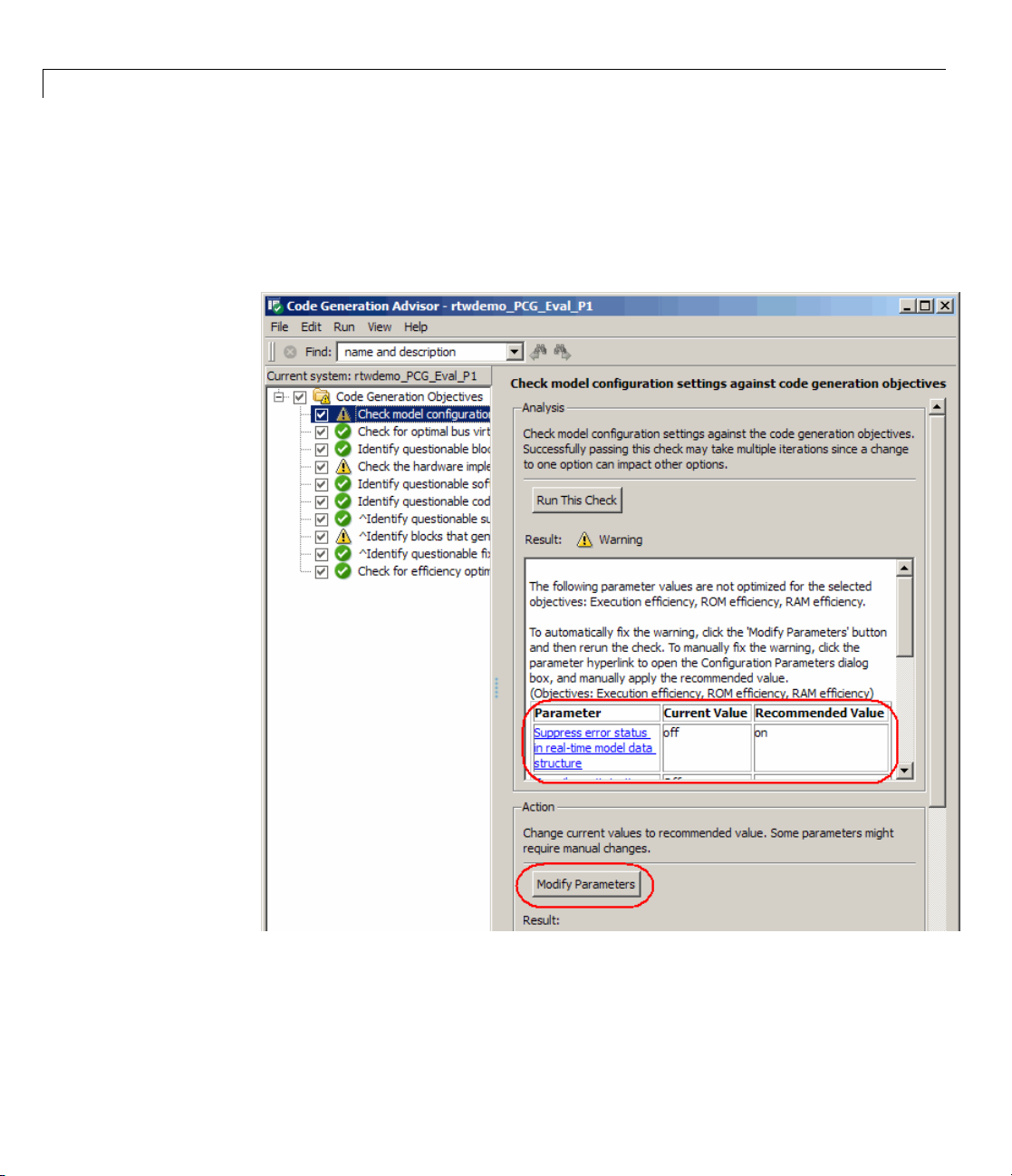
The Code Generation Advisor dynamically creates the list of checks based on
the objectives that you select. The first check reviews the current values of
the configuration parameters and recommends values based on the objectives.
The check provides an automated method for setting the parameters to the
recommended values.
®
Embedded Coder™ Software
2-16
For more information about using the Code Generation Advisor, see
“Determining Whether the Model is Configured for Specified O bjectives ”.
Page 45

Understanding the Demo Model
Manually Setting Configuration Options
You can manually specify the configuration parameters. To view the
Configuration Parameters dialog box, from the Model Editor Simulation
menu, select
Configuration Parameters dialog box in the Model Explorer window, from the
Model Editor View menu, select
This tutorial focuses on four areas of model configuration:
• Solver options
• Optimization options
• Hardware implementation options
• Real-Time Workshop options
Perform the following steps to explore model configuration options.
1 Open the demo model rtwdemo_PCG_Eval_P1 by entering
rtwdemo_PCG_Eval_P1 at the MATLAB command line.
Configuration Parameters. Alternatively, to view the
Model Explorer.
2 Open Model Explorer and click Configuration (Active) in the Model
Hierarchy pane.
3 Open the Solver pane.
2-17
Page 46

2 Learning and Using Real-Time Workshop
For Real-Time Workshop software to generate code for a model, you must
configurethemodeltouseafixed-stepsolver. Thestartandstoptimedo
notaffectgeneratedcode.
®
Embedded Coder™ Software
Option
Required Setting
Effect on Generated
Code
Start time and Stop
Any No effect
time
Type
Fixed-step
Enables code
generation
Solver Any Controls selection of
integration technique
used to compute the
state derivative of the
model
Fixed-step size Must be lowest
common multiple of
Sets base rate of the
system
all rates in the system
Tasking mode for
periodic sample
times
SingleTasking or
MultiTasking
MultiTasking
generates one entry
point function for each
rate in the system
4 Open the Optimization pane.
2-18
Page 47

Understanding the Demo Model
ptimization pane includes the following subpanes.
The O
2-19
Page 48

2 Learning and Using Real-Time Workshop
®
Embedded Coder™ Software
Subpane
Effect
Simulation and code generation Removes unused branches from
the code and controls creation of
temporary variables
Signals Controls code optimizations
related to signals — for example,
reduces the number of temporary
variables created by collapsing
multiple computations into a
single assignment and by reusing
temporary variables
Data initialization
Controls which signals have explicit
initialization code
Integer and fixed-poin t Enables and disables use of
overflow and division-by-zero
protection code
Stateflow Controls how the Stateflow
software stores bit-wise information
Accelerating simulations Provides control over builds for
simulations involving accelerator
modes or referenced models — no
effect on Real-Time Workshop code
generation
2-20
5 Open the Hardware Implementation pane.
Page 49

Understanding the Demo Model
Use hardware implementation pa rameters to specify the word size and
byte ordering of the target hardware. This demo model targets a generic
32-bit embedded processor.
6 Open the R
eal-Time Workshop pane.
2-21
Page 50

2 Learning and Using Real-Time Workshop
®
Embedded Coder™ Software
2-22
eal-Time Workshop pane is where you specify the system target
The R
(STF) and the language for your generated code. This demo model
file
s the Real-Time Workshop Embedded Coder STF (
use
guage. You can extend the STF to create a customized configuration.
lan
e of the basic configuration options reachable from the Real-Time
Som
kshop pane include:
Wor
ert.tlc)andtheC
Page 51

Understanding the Demo Model
• Selection of the code generator target:
ert.tlc — base Embedded Real-Time Target
–
grt.tlc — base Generic Real-Time Target
–
– Hardware-specific targets
• Selection of code generation language:
C —Ccode
–
C++ — C++ compatib le code
–
C++ (Encapsulated) — C++ code with a model class that
–
encapsulates model data and entry-point functions
• Build process options including selection of make file and compiler
optimizations
• Additional categories of options on subsidiary panes, such as Report,
Comments, Symbols, Custom Code, Debug, Interface, Code Style,
and Templates, among others.
• Code formatting options:
– Line length
– Use of parentheses
– Header file information
– Variable naming conventions
• Inclusion of custom code:
– Cfiles
– Hfiles
– Object files
– Directory paths
• Generation of ASAP2 files
• Code generation objectives options to identify changes to model
constructs and settings that improve the generated code (see “Mapping
Application Objectives to Model Configuration Parameters”).
2-23
Page 52

2 Learning and Using Real-Time Workshop
The Real-Time Workshop pane also contains a Build button that you can
use to build your model. If you select the option Generate code only,the
button is relabeled to Generate code.
Saving the Configuration Parameters as a MATLAB Function
You can save the settings of configuration parameters as a MATLAB function.
At the command line, enter:
hCs = getActiveConfigSet('rtwdemo_PCG_Eval_P1');
hCs.saveAs('ConfiguredData');
You can use the MATLAB function to:
• Archive the configuration parameters for a model.
• Compare different versions of the configuration parameters using
traditional differencing tools.
®
Embedded Coder™ Software
2-24
• Set the co nfiguration parameters of other models.
Running the MATLAB function sets the configuration parameters of other
models. For example, to set the configuration parameters for a model called
myModel, at the command line, enter:
hCs2 = ConfiguredData;
attachConfigSet('myModel', hCs2, true);
setActiveConfigSet('myModel', hCs2.Name);
For more information, see “Saving Configurati on Sets” and “Loading Saved
Configuration Sets” in the Simulink documentation.
Generating Code for the Model
Perform the following steps to generate code for the demo model that
implements the control algorithm.
1 Set up your C compiler by entering mex -setup at the MATLAB command
line and specifying a valid, installed compiler.
Page 53

Understanding the Demo Model
2 Check that your working directory is set to a writable directory, such as the
directory to which you copied the tutorial demos.
3 Open the rtwdemo_PCG_eval_P1 demo model and use one of the following
methods to generate code:
• Click the Generate code button in the Configuration Parameters >
Real-Time Workshop pane.
• Select Tools > Real-Time Workshop > Build Model.
The Real-Time Workshop build process generate s several files. The
resulting code, while computationally efficient, is not yet organized for
integration into the production environment.
Examining the Generated Code
Building the rtwdemo_PCG_eval_P1 demo model generates multiple files into
a subdirectory of your current working directory. In addition to the standard
C a nd H files, the build process generates an HTML code generation report,
which provides active links between the code and the model.
Perform the following steps to examine the generated code for the demo model
that implements the control algorithm.
1 Generate code for the rtwdemo_PCG_eval_P1 demo model using one of
the methods described in the previous section, “Generating Code for the
Model” on page 2-24.
2 Open Model Explorer, and in the Model Hierarchy pane, select Code for
rtwdemo_PCG_Eval_P1.
3 In Model Explorer Contents pane for the generated model code, select
HTML Report. Model Explorer displays the HTML code generation report
for the
4 In the HTML report, click the link for the generated file
rtwdemo_PCG_Eval_P1.c and examine the generated code. Notice that:
• All of the controller code is in one function,
rtwdemo_PCG_eval_P1 demo model.
rtwdemo_PCG_Eval_P1_step.
• The operations of multiple blocks are in one equation.
• The
rtwdemo_PCG_Eval_P1_initialize function initializes v ariables.
2-25
Page 54

2 Learning and Using Real-Time Workshop
• Real-Time Workshop data structures (for example,
rtwdemo_PCG_Eval_P1_U.pos_rqst)definealldata.
• You can click links in the HTML report to display and highlight the
corresponding model block. For example, as shown below, you can
click the link
the corresponding Sum block in your model (as well as the
subsystem block that contains it).
®
Embedded Coder™ Software
<S2>/Sum2 in the HTML report to highlig ht and display
PI_ctrl_1
2-26
5 Close the rtwdemo_PCG_eval_P1 demo model.
You can view any of the files listed below by clicking their links in the HTML
report Contents pane, or by exploring the generated code subdirectory
created in your working directory by the build process.
File
rtwdemo_PCG_Eval_P1.c
Description
C file with step and initialization
functions
rtwdemo_PCG_Eval_P1_data.c
C file that assigns values to
Real-Time Workshop data structures
ert_main.c
Example main module that includes
a simple scheduler
rtwdemo_PCG_Eval_P1.h
H file that defines data structures
Page 55

Understanding the Demo Model
File
PCG_Eval_p1_private.h
rtwdemo_PCG_Eval_P1_types.h
Description
File that defines data used only by
the generated code
H file that defines the model data
structure
Topics for Further Study
• “Supporting M odel Referencing” in the Real-Time Workshop documentation
• “Building Executables” in the Real-Time W orkshop documentation
• “Configuration Parameters” in the Real-Time Workshop Embedded Coder
documentation
• “Working with Signal Groups” in the Simulink documentation
• Simulink Verification and Validation documentation
2-27
Page 56

2 Learning and Using Real-Time Workshop
®
Embedded Coder™ Software
Configuring the Data Interface
In this section...
“Introduction” on page 2-28
“Declaring Data” on page 2-28
“Using Data Objects in Simulink Models and Stateflow Charts” on page 2-31
“Adding New Data Objects” on page 2-34
“Configuring Data Objects” on page 2-35
“Controlling File Placement o f Parameter Data” on page 2-35
“Enabling D ata Objects in Generated Code” on page 2-36
“Effects of Simulation on Data Typing” on page 2-37
“Viewing Data Objects in Generated Code” on page 2-39
“Managing Data” on page 2-42
“Topics for Further Study” on page 2-42
2-28
Introduction
This tutorial explains how to configure the data in ter fa ce for the genera ted
code of a mode l. In this tutorial, you learn how to control the following
attributes of signals and parameters in the generated code:
• Name
• Data type
• Data storage class
Declaring Data
Most programming languages require that you declare data before using it.
The declaration specifies the following:
Page 57

Configuring the Data Interface
Data
Description
Attribute
Scope The region of the program that has access to the data
Duration The p eriod dur in g which the data is resident in memory
Data type
Initialization
The amount of memory allocated for the data
An initial value, a pointer to memory, or NULL (if you do
not provide an initial value, most compilers assign a z ero
value or a null pointer)
The following data types are supported for code gen e ration .
Supported Data Types
Name
double
single
int8
uint8
int16
uint16
int32
uint32
Description
Double-precision floating point
Single-precision floating point
Signed 8-bit integer
Unsigned 8-bit integer
Signed 16-bit integer
Unsigned 16-bit integer
Signed 32-bit integer
Unsigned 32-bit integer
Fixed point
8-, 16-, 32-bit word lengths
data types
The combination of scope and duration comprises the storage class of a
data item. The following p redefined storage classes are supported for code
generation.
2-29
Page 58

2 Learning and Using Real-Time Workshop
Supported Predefined Storage Classes
®
Embedded Coder™ Software
Name
Const
ConstVolatile
Volatile
ExportToFile
ImportFromFile
Exported
Global
Imported
Extern
Description
Use const type
qualifier in
declaration
Use const
volatile
type
qualifier in
declaration
Use volatile
type qualifier in
declaration
Generate and
include files, with
user-specified
name, containing
global variable
declarations and
definitions
Include
predefined
header files
containing
global variable
declarations
Declare and
define variables
of global scope
Import a variable
defined outside of
the scope of the
model
Parameters
Supported
Signals
Supported
YN
YN
YY
YY
YY
YY
YY
Data Types
All
All
All
All
All
All
All
2-30
Page 59

Supported Predefined Storage Classes (Continued)
Configuring the Data Interface
Name
BitField
Define
Struct
Description
Embed Boolean
data in a named
bit field
Represent
parameters with
a
#define macro
Embed data in a
named structure
to encapsulate
sets of data
Parameters
Supported
YY
YN
YY
Signals
Supported
Data Types
Boolean
All
All
Using Data Objects in Simulink Models and Stateflow Charts
Twomethodsareavailablefordeclaring data in Simulink models and
Stateflow charts: data objects and direct specification. Thistutorialusesthe
data object method. Both methods allow full control over the data type and
storage class. You can mix the two methods in a single model.
You can use data objects in a variety of ways in the MATLAB and Simulink
environment. T he tutorial focuses on three types of data objects:
• Signal
• Parameter
• Bus
To configure the data interface for your model using the data object method,
youdefinedataobjectsintheMATLABbaseworkspaceandthenassociate
them with your Simulink model or embedded Stateflow chart. When you
build your model, the Real-Time Workshop build process uses the associated
base workspace data objects in the generated code.
2-31
Page 60

2 Learning and Using Real-Time Workshop
A data object has a mixture of active and descriptive fields. Active fields affect
simulation or code generation. Descriptive fields do not affect simulation or
code generation, but are used with data dictionaries and model-checking tools.
• Active fields:
- Data type
- Storage class
- Value (parameters)
- Initial value (signals)
- Alias (define a different name in the generated code)
- Dimension (inherited for parameters)
- Complexity (inherited for parameters)
• Descriptive fields:
- Minimum
®
Embedded Coder™ Software
2-32
- Maximum
- Units
- Description
You can create and inspect base workspace data objects by entering commands
at the MATLAB command line or by using Model Explorer. Perform the
following steps to explore base workspace signal data objects declared for the
rtwdemo_PCG_Eval_P2 demo model.
1 Open the rtwdemo_PCG_Eval_P2 demo model by entering
rtwdemo_PCG_Eval_P2 at the MATLAB command line.
2 Open Model Explorer.
3 Select Base Workspace.
4 Select the pos_cmd_one signal data object for viewing
Page 61

Configuring the Data Interface
You can also view the definition of Simulink signal object pos_cmd_one by
entering
pos_cmd_one at the MATLAB command line:
pos_cmd_one =
Simulink.Signal (handle)
RTWInfo: [1x1 Simulink.SignalRTWInfo]
Description: 'Throttle position command from the fir st PI controller'
DataType: 'double'
Min: -1
Max: 1
DocUnits: 'Norm'
Dimensions: -1
Complexity: 'auto'
SampleTime: -1
SamplingMode: 'auto'
InitialValue: '0'
2-33
Page 62

2 Learning and Using Real-Time Workshop
5 To view other signal objects, click the object name in Model Explorer or
enter the object name at the MATLAB command line. The following table
summarizes object characteristics for this model.
®
Embedded Coder™ Software
Object
pos_cmd_one pos_rqst P_InErrMap
Characteristics
Description Top-level
output
Data type
Storage c lass
Double Double
Exported
global
* ThrottleCommands definesaSimulinkBusobject;ThrotComm is the
instantiation of the bus. If the bus is a nonvirtual bus, the signal generates
a structure in the C code.
As in C, yo u can use a bus definition (
multiple instances of the structure. In a model diagram, a bus object appears
as a wide line with central dashes, as shown below.
Top-level
input
Imported
extern
pointer
Calibration
parameter
ThrotComm
Top-level
output
* ThrottleCommands*
Bus definition
structure
Auto Auto Structure
Constant
Exported
None
global
ThrottleCommands) to instantiate
2-34
Adding New Data Objects
You can create data objects for named signals, states, and parameters. To
associate a data object with a construct, the construct must have a name.
TheDataObjectWizardisatoolthatfindsconstructsforwhichyoucan
create data objects, and then creates the objects for you. The model includes
two signals that are not associated with data objects:
fbk_1 and pos_cmd_ two.
Page 63

Configuring the Data Interface
To find the signals and create data objects for them:
1 Open the Data Object Wizard by selecting Tools > Data Object Wizard
in the Model E ditor.
2 Click the Find button to find candidate constructs.
3 Click the Check All button to select all candidates.
4 Click the Apply Package button to apply the default Simulink package
for the data objects.
5 Click the Create button to create the data objects.
Configuring Data Objects
Thenextstepistosetthedatatypeandstorageclass:
1 Open Model Explorer and view the base workspace.
2 For each object listed in the following table:
a Click the signal name in the Contents pane.
b Change the settings in the Data pane to match those in the table.
c Click the Apply button.
Signal
fbk_1 double ImportedExtern
pos_cmd_two double Expo rted Global
Data Type
Storage Class
Controlling File Placement of Parameter Data
Real-Time Workshop Embedded Coder software allows you to control the files
that define the parameters and constants. In this tutorial, all parameters
are in
To change the placement of parameter and constant definitions, set the
appropriate data placement options.
eval_data.c.
2-35
Page 64

2 Learning and Using Real-Time Workshop
1 Within Model Explorer, enter the data options in the
Configuration > Real-Time Workshop > Data Placement
pane, as shown in the following figure.
2 eval_data.c is shown below:
®
Embedded Coder™ Software
/* Const m
17 /* Defi
18 const r
19 const
20 1.0 } ;
21
22 cons
23
24 cons
25 cons
26
27 con
emory section */
nition for custom storag e class: Const */
eal_T I_Gain = -0.03;
real_T I_InErrMap[9] = { -1.0, -0.5, -0.25, -0.05, 0.0, 0.05, 0.25, 0.5,
t real_T I_OutMap[9]={1.0,0.75, 0.6, 0.0, 0.0, 0.0, 0.6, 0.75, 1.0 } ;
t real_T P_Gain = 0.74;
t real_T P_InErrMap[7] = { -1.0, -0.25, -0.01, 0.0, 0.01, 0.25, 1.0 } ;
st real_T P_OutMap[7]={1.0,0.25, 0.0, 0.0, 0.0, 0.25, 1.0 } ;
Enabling Data Objects in Generated Code
The next step is to ensure that the data objects you have created appear in
the generated code:
1 In Model Explorer, make sure the
Configuration > Optimizations > Inline parameters check box
is selected.
able a sign al in generated code:
2 En
2-36
Page 65

Configuring the Data Interface
a In the model, right-click the pos_cmd_one signal line.
b Select Signal Properties. A Signal Properties dialog box appears.
c Make sure the Signal name must resolve to a Simulink signal
object check box is selected.
3 Enable all of the signals in the model simultaneously by entering the
following at the MATLAB command line:
disableimplicitsignalresolution('rtwdemo_PCG_Eval_P2')
4 Save the model (requires a Stateflow license) for use in the next section.
EffectsofSimulationonDataTyping
In the rtwdemo_PCG_Eval_P2 model, all data types are set to double.Since
Simulink software uses the
expect changes in the model behavior when you run the generated code.
You verify this b y running the test harness. You update the test harness to
double data type for simulation, you should not
2-37
Page 66

2 Learning and Using Real-Time Workshop
include the rtwdemo_PCG_Eval_P2 model. That change is the only one made
to the test harness.
Note The following procedure requires a Stateflow license.
1 Open the test harness by entering rtwdemo_PCGEvalHarness at the
MATLAB command line.
2 Right-click the Unit_Under_Test Model block and select ModelReference
Parameters.
3 Set Model name (without the .mdl extension) to:
rtwdemo_PCG_Eval_P2.
4 Click OK.
5 Simulate the test harness.
®
Embedded Coder™ Software
2-38
The resulting plot show s that the difference between the golden and
simulated versions of the model remains zero.
Page 67

Configuring the Data Interface
6 Close the rtwdemo_PCGEvalHarness model.
Viewing Data Objects in Generated Code
View the rtwdemo_PCG_Eval_P2.c file to see how using data objects changes
the generated code.
1 Generate code from the rtw demo _PCG_Eval_P2 model.
2 View t
rtwd
this
The following code for the
equivalent to
data objects. The highlighted portions indicate parameter and structure
variables that user defined data objects replace.
he generated code for the model step function in
emo_PCG_Eval_P2.c
, which is in the generated code subdirectory for
model.
rtwdemo_PCG_EVAL_P1_step function is
rtwdemo_PCG_Eval_P2_step function before the use of
2-39
Page 68

2 Learning and Using Real-Time Workshop
/* Model step function */
void rtwdemo_PCG_Eval_P1_step(void)
{
{
real_T rtb_Sum3;
real_T rtb_Saturation1;
/* Sum: '<S2>/Sum2' incorporates:
* Inport: '<Root>/fbk_1'
* Inport: '<Root>/pos_rqst'
*/
rtb_Sum3 = rtwdemo_PCG_Eval_P1_U.pos_rqst - rtwdemo_PCG_Eval_P1_U.fbk_1;
/* DiscreteIntegrator: '<S2>/Discrete_Time_Integrator1' incorporates:
* Gain: '<S2>/Int Gain1'
* Lookup: '<S2>/Integral Gain Shape'
* Product: '<S2>/Product3'
*/
rtwdemo_PCG_Eval_P1_B.Discrete_Time_Integrator1 = -0.03 * rt_Lookup((real_T *)
(&rtwdemo_PCG_Eval_P1_ConstP.pooled4[0]), 9, rtb_Sum3, (real_T *)
(&rtwdemo_PCG_Eval_P1_ConstP.pooled5[0])) * rtb_Sum3 * 0.001 +
rtwdemo_PCG_Eval_P1_DWork.Discrete_Time_Integrator1_DSTAT;
...
®
Embedded Coder™ Software
2-40
The following code for the rtwdemo_PCG_ Eval _P2_step
function shows that most of the Real-Time Workshop data
structures have been replaced with user-defined data objects
(highlighted). The local variable
rtwdemo_PCG_Eval_P2_DWork.Discrete_Time_Integrator1_DSAT use
rtb_Sum3 and the state variable
Real-Time Workshop data structures.
/* Model step function */
void rtwdemo_PCG_Eval_P2_step(void)
{
{
real_T rtb_Sum3;
/* Sum: '<S2>/Sum2' incorporates:
* Inport: '<Root>/fbk_1'
* Inport: '<Root>/pos_rqst'
*/
Page 69

Configuring the Data Interface
rtb_Sum3 = (*pos_rqst)-fbk_1;
/* DiscreteIntegrator: '<S2>/Discrete_Time_Integrator1' incorporates:
* Gain: '<S2>/Int_Gain1'
* Lookup: '<S2>/Integral Gain Shape'
* Product: '<S2>/Product3'
*/
rtwdemo_PCG_Eval_P2_B.Discrete_Time_Integrator1 = I_Gain * rt_Lookup((real_T*)
(&(I_InErrMap[0])), 9, rtb_Sum3, (real_T *)
(&(I_OutMap[0]))) * rtb_Sum3 *
0.001 + rtwdemo_PCG_Eval_P2_DWork.Discrete_Time_Integrator1_DSTAT;
...
3 Close the rtwdemo_PCG_eval_P2 demo model.
Thefollowingtableliststhefilesthat the code generator creates:
Files Generated for
File
rtwdemo_PCG_Eval_P2.c
eval_data.c
eval_data.h
ert_main.c
rtwdemo_PCG_Eval_P2.h
PCG_Eval_p2_private.h
rtwdemo_PCG_Eval_P2
Definition
Provides step and
initialization function
Assigns values to the defined
parameters
Provides extern definitions to
the defined parameters
Provides scheduling
functions
Defines data structures Using data objects shifted
Defines private (local) data
for the generated functions
Notes
Uses the defined data objects
Has the file name specifically
defined
Has the file name specifically
defined
No change
some parameters out of this
file into
user_data.h
Objects now defined in
eval_data were removed
2-41
Page 70

2 Learning and Using Real-Time Workshop
Files Generated for rtwde mo_P CG_Eval_P2 (Continued)
®
Embedded Coder™ Software
File
rtwdemo_PCG_Eval_P2_types.h
rtwtypes.h
Managing Data
Data objects exist in the MATLAB base workspace, in a separate file from the
model. To save the data manually, enter
The separation of data from the model provides many benefits:
• One model, multiple data sets:
- Use of different data types to change the targeted hardware (for example,
for floating-point and fixed-point targets)
- Use of different parameter values to change the behavior of the
control algorithm (for example, for reusable components with different
calibration values)
• Multiple models, one data set:
Definition
Defines the model data
structure
Provides mapping to data
types defined by Real-Time
Workshop software
save at the MATLAB command line.
Notes
No change
Used for integration with
external systems
2-42
- Sharin g of data betw e en Simulink models in a system
- Sharing of data between projects (for example, transmission, engine, and
wheel controllers might a ll use the same CAN message data set)
Topics for Further Study
• “Working with Data” in the Simulink documentation
• “Creating and Using Custom Storage Classes” in the Real-Time Workshop
Embedded Coder documentation
• “Managing Placement of Data Definitions and Declarations” in the
Real-Time Workshop Embedded Coder documentation
Page 71

Partitioning Functions in the Generated Code
Partitioning Functions in the Generated Code
In this section...
“Introduction” on page 2-43
“About Atomic and Virtual Subsystems” on page 2-43
“Viewing Changes in the Model Architecture” on page 2-44
“Controlling Function Location and File Placement in Generated Code”
on page 2-45
“Understanding Reentrant Code” on page 2-46
“Using a Mask to Pass Parameters into a Library Subsystem” on page 2-47
“Generating Code from an Atomic Subsystem” on page 2-48
“Generating Code: Full Model vs. Exported Functions” on page 2-49
“Effect of Execution Order on Simulation Results” on page 2-51
“Topics for Further Study” on page 2-53
Introduction
This tutorial shows how to associate subsystems in the model with specific
function names and files. You examine:
• How to specify function and file names in generated code
• Parts of generated code that you must have for integration
• Howtogeneratecodeforatomicsubsystems
• Data that you must have to execute a generated function
About Atomic and Vir tual Subsystems
The models in “Understanding the Demo Model” on page 2-5 and “Configuring
the Data Interface” on page 2-28 use virtual subsystems. Virtual subsystems
visually organize blocks but have no effect on the behavior of the model.
Atomic subsystems evaluate all included blocks as a unit. In addition, atomic
subsystems allow you to specify additional function partitioning information.
Atomic subsystems display graphically with a bold border.
2-43
Page 72

2 Learning and Using Real-Time Workshop
®
Embedded Coder™ Software
Viewing Changes
This section sho
with function-c
• Are always atom
• Allow the dire
• Are associate
• Are executed
You might ha
model to mat
The followi
subsystem
ws you how to replace the virtual subsystems in the model
all subsystems. Function-call subsystems:
ic subsystems
ct control of subsystem execution order
d with a function-call signal
when the function-call signal is triggered
ve to exert direct control over executio n order if you intend the
ch an existing system with a specific execution order.
ng figure of the
sas
PI_ctrl_1, PI_ctrl_2,andPos_Command_Arbitration.
in the Model Architecture
rtwdemo_PCG_Eval_P3 model identifies function-call
2-44
The Executi on_O rder_Control subsystem has been added to the model. It
is a Stateflow chart that models the calling functionality of a scheduler. It
Page 73

Partitioning Functions in the Generated Code
controls the execution order of the function-call subsystems. Later, this
tutorial examines how changing execution order can change the simulation
results.
Four signal conversion blocks were added to the outports for the PI controllers
to make the functions reentrant.
Controlling Function L ocation and F ile Placement in
Generated Code
In“UnderstandingtheDemoModel”onpage2-5and“ConfiguringtheData
Interface” on page 2-28, Real-Time Workshop software generates a single
model_step function that contains all the control algorithm code. However,
many applications require a greater level of control over the location of
functions in the generated code. By using atomic subsystems, you can specify
multiple functions within a single model. You specify this information by
modifying subsystem parameters, shown in the following figure.
Parameter
Treat as
atomic unit
Sample time Specifies a sample time. Not present for function-call
Real-Time
Workshop
system code
What the Parameter Does
Enables other submenus. This parameter is automatically
selected and grayed out for atomic subsystems.
subsystems.
Depends on setting, as follows.
Auto: Real-Time Workshop software determines how
the subsystem appears in the generated code. This is the
default.
Inline: Real-Time Workshop software places the
subsystemcodeinlinewiththerestofthemodelcode.
Function: Real-Time Workshop software generates the
code for the subsystem as a function.
Reusable function: Real-Time Workshop software
generates a reusable function from the subsystem. Passes
all input and output into the function by argument or by
reference. Does not pass g lobal variables into the function.
2-45
Page 74

2 Learning and Using Real-Time Workshop
®
Embedded Coder™ Software
Parameter
Real-Time
Workshop
function
name
options
Real-Time
Workshop
file name
options
What the Parameter Does
If you select Function or Reusable function, function
name options are enabled as follows.
Auto: R eal-Time Workshop software determines the
function.
Use subsystem name: Base the function name on the
subsystem name.
User Specified: You specify a unique file name.
If you select Function or Reusable function,filename
options are enabled as follows.
Auto: Real-Time Workshop software generates the
function code within the generated code from the parent
system or, if the parent of the subsystem is the model
itself, within the
Use subsystem name: Real-Time Workshop software
model.c file.
generates a separate file and names it with the name of the
subsystem or library block.
Use function name: Real-Time Workshop software
generates a separate file and names it with the function
name specified for Real-Time Workshop function name
options.
2-46
User Specified: You specify a unique file name.
Function
with
separate
data
Enabled when you set Real-Time Workshop system
code to
Function. If selected, Real-Time Workshop
Embedded Coder software generates subsystem function
code in which the internal data for an atomic subsystem
is separated from its parent model and is owned by the
subsystem.
Understanding Reentrant Code
Real-Time Workshop Embedded Coder software supports reentrant code.
Reentrant code is a reusable programming routine that multiple programs
can use simultaneously. Operating systems and other system software
that uses multithreading to handle concurrent events use reentrant code.
Page 75

Partitioning Functions in the Generated Code
Reentrant code does not maintain state data: no persistent variables are in
the function. Calling programs maintain their state variables and pass them
into the function. Any number of users or processes can share one copy of
a reentrant routine.
To generate reentrant code, you must first specify the subsystem as a
candidate f or reuse by specifying the subsystem parameters in the Function
Block Parameters dialog box.
In s ome cases, the configuration of the model prevents Real-Time Workshop
software from generating reusable code. Common issues that prevent the
generation of reentrant code and corresponding solutions follow.
Cause
Use of global data
on the outport of the
subsystem
Passing data into
the system as
pointers
Use of global
data inside the
subsystem
Solution
Add a Signal Conversion block between the subsystem
and the signal definition .
In Model Explorer, select the
Configuration > Model Referencing > Pass
fixed-size scalar root inputs by value check box.
Use a port to pass the global data in and out of the
subsystem.
Using a Mask to Pass Parameters into a Library Subsystem
Subsystem masks enable Simulink software to define subsystem parameters
outside the scope of a library block. By changing the parameter value at the
top o f the l ib rary, th e same library is usable with multiple sets of parameters
within the same model.
When a subsystem is reusable and masked, Re al-Time Workshop software
passes the masked parameters into the reentrant code as arguments.
Real-Time Workshop software fully supports the use of data objects in masks.
The data objects are used in the generated code.
2-47
Page 76

2 Learning and Using Real-Time Workshop
In the rtwdemo_PCG_Eval_P3 model, the PI_ctrl_1 and PI_ctrl_2
subsystems are masked. The value of the P and I gains are set in the
subsystem Mask Parameters dialog box, shown in the following figure.
Simulink creates two new data objects:
®
Embedded Coder™ Software
P_Gain_2 and I_Gain_2.
2-48
Generating Code from an Atomic Subsystem
In“UnderstandingtheDemoModel”onpage2-5and“ConfiguringtheData
Interface” on page 2-28, the Real-Time Workshop software generates code at
the model root level. In addition to building at the system level, it is possible
to build at the subsystem level
You start a subsystem build from the right-click context menu. Three
different options are available for a subsystem build.
Page 77

Build Option What the Option Does
Partitioning Functions in the Generated Code
Build
Subsystem
Generate
S-Function
Export
Functions
Treats the subsystem as a separate model. The full set of source C files and
header files are created for the subsystem. Does not support function-call
subsystems.
Generates C code for the subsystem and creates an S-function wrapper. You
can then simulate the code in the original Simulink model. Does not support
function-call subsystems.
Generates C code without the scheduling code associated wi th the Build
Subsystem option. Export functions is required when building subsystems
that use triggers.
Generating Code: Full Model vs. Exported Functions
In this section, you compare the files generated for the full model build with
files generated for exported functions. This module also examines how the
masked data appears in the code.
1 Open rtwdemo_PCG_Eval_P3.
2 Generate code for the model.
The code generator creates code for the
3 Export a function for the PI_ctrl_1 subsystem:
rtwdemo_PCG_Eval_P3 model.
a In the Model Editor, right-click PI_ctrl_1 and select Real-Time
Workshop > Export Functions.
The Build code for Subsystem: PI_ctrl_1 dialog box opens.
b Click the Build button.
Code is generated for
4 If you have a Stateflow license, export a function for the
Pos_Command_Arbitration chart:
a In the Model Ed itor, right-click Pos_Command_Arbitration and select
PI_ctrl_1.
Real-Time Workshop > Export Functions.
2-49
Page 78

2 Learning and Using Real-Time Workshop
The Build code for Subsystem: Pos_Comm and_Arbitration dialog
box opens.
b Click the Build button.
®
Embedded Coder™ Software
Code is generated for
5 Examine the generated code listed in the table by locating and opening the
files in the respective generated code subdirectories.
File Full Build
rtwdemo_PCG_Eval_P3.c
Yes
Step function
PI_ctrl_1.c
Pos_Command_Arbitration.c
No Yes
No No Yes
(requires Stateflow license)
PI_Ctrl_Reusable.c
Yes
Called by main
ert_main.c
eval_data.c
Yes Yes Yes
Yes* Yes*
Pos_Command_Arbitration.
PI_ctrl_1 Pos_Command_Arbitration
(requires Stateflow
license)
No No
No
Trigger function
Init and Function
Yes
No
Called by
PI_ctrl_1
No
Eval data not used in
diagram
2-50
* The content of e val_data.c differs between the full model and export
function builds. The full model build includes all parameters that the
model uses while the export function contains only variables that the
subsystem uses.
Masked Data in the Generated Code
The code in rtwdemo_PCG_Eval_P3.c illustrates how data objects from
the mask (
reentrant code.
P_Gain and I_Gain)andP_Gain_2 and I_Gain_2 pass into the
Page 79

Partitioning Functions in the Generated Code
PI_Cntrl_Reusable((*pos_rqst), fbk_1, &rtwdemo_PCG_Eval_P3_B->PI_ctrl_1,
&rtwdemo_PCG_Eval_P3_DWork->PI_ctrl_1, I_Gain, P_Gain);
PI_Cntrl_Reusable((*pos_rqst), fbk_2, &rtwdemo_PCG_Eval_P3_B->PI_ctrl_2,
&rtwdemo_PCG_Eval_P3_DWork->PI_ctrl_2, I_Gain_2, P_Gain_2);
Effect of Execution Order on Simulation Results
Without explicit control, Simulink software s ets the execution o rde r of the
subsystems as:
1 PI_ctrl_1
2 PI_ctrl_2
3 Pos_Cmd_Arbitration
You use the test harness to see the effect of the executio n o rde r on
the simulation results. The
configurable subsystem with two configurations that change the execution
order of the subsystems.
Execution_Order_Control subsystem is a
Note The following procedure requires a Stateflow license.
Change the execution order as follows:
1 In the rtwdemo_PCG_Eval_P3 model, set the execution order to PI_ctrl_1,
PI_ctrl_2, Pos_cmd_Arbitration:
a Right-click the Execution_Order_Control subsystem.
b On the Block Choice menu, select
PI_1_then_PI_2_then_Pos_Cmd_Arb.
2 Save rtwdemo_PCG_Eval_P3.
3 Open the test harness, rtwdemo_PCGEvalHarness.
4 Right-click the Unit_Under_Test Model block and select ModelReference
Parameters.
2-51
Page 80

2 Learning and Using Real-Time Workshop
5 Set Model name (without the .mdl extension) to:
rtwdemo_PCG_Eval_P3.
6 Click OK.
7 Run the test harness.
8 In rtwdemo_PCG_Eval_P3, change the execution order to
Pos_cmd_Arbitration_then_PI_1_then_PI_2.
9 Run the test harness again.
A slight variation exists in the output results depending on the order
of execution. The difference is most noticeable when the desired input
changes.
®
Embedded Coder™ Software
2-52
Page 81

Partitioning Functions in the Generated Code
10 Close the rtwdemo_PCG_Eval_P3 model.
Topics for Further Study
• “Architecture Considerations” in the Real-Time Workshop documentation
• “Integrating External Code With Generated C and C++ Code” in the
Real-Time Workshop documentation
• “Exporting Function-Call Subsystems” in the Real-Time Workshop
Embedded Coder documentation
• “Controlling Generation of Function Prototypes” in the Real-Time
Workshop Embedded Coder documentation
• “Working with Block Masks” in the Simulink documentation
2-53
Page 82

2 Learning and Using Real-Time Workshop
®
Embedded Coder™ Software
Calling External C Functions from the Model and Generated Code
In this section...
“Introduction” on page 2-54
“Including Preexisting C Functions in a Simulink Model” on page 2-54
“Creating a Block That Calls a C Function” on page 2-55
“Validating the External Code in the Simulink Environment” on page 2-56
“Validating the C Code as Part of the Simulink Model” on page 2-58
“Calling the C Function from the Generated Code” on page 2-59
“Topics for Further Study” on page 2-60
Introduction
This tutorial introduces the Legacy Code Tool as a method for calling external
functions. The Legacy Code Tool enables you to call the external function
from within the simulation and in the generated code.
2-54
In this tutorial, you examine:
• HowtoevaluateaCfunctionaspart of a Simulink model simulation
• How to call a C function from code that Real-Time Workshop software
generates
Including Preexisting C Functions in a Simulink Model
Simulink models are one part of Mod el-Based Design. For many applications,
a d esign also includes a set of C functions that you have created, tested, and
validated. The ability to integrate these functions easily into a Simulink
model and generated code is critical to using Simulink software in the controls
development process.
This section demonstrates how to create a custom Simulink block that calls
an existing C function. Once the b lo ck is part of the model, you can take
advantage of the simulation environment to test the system further.
Page 83

Calling External C Functions from the Model and G enerated Code
In “Creating a Block That Calls a C Function” on page 2-55, you replace the
Lookup Table blocks in the PI controllers with calls to an existing C function.
The function is defined in the files
matlabroot/toolbox/rtw/rtwdemos/EmbeddedCoderOve
matlabroot/toolbox/rtw/rtwdemos/EmbeddedCoderO
rview/stage_4_files/SimpleTable.c
verview/stage_4_files/SimpleTable.h
Note matlabroot represents the name of your top-level MATLAB
installation directory.
Creating a Block That Calls a C Function
To specify a call to an existing C function, you use an S-Function block.
You can automate the process of creating the S-Function block by using the
Simulink Legacy Code Tool. Using this tool, you specify an interface for your
existing C function. The tool then uses that interface to automate creation of
an S-Function block.
Complete the steps below to create an S-Function block for an existing C
function
1 Copy the SimpleTable.c and SimpleTable.h files to your working
2 Create an S-Function block that calls the specified function at each time
SimpleTable.c.
directory.
step during simulation:
a Create the function interface definition structure at the command line:
def=legacy_code('initialize')
The data structure def defines the function interface to the existing
C code.
b Populate the function interface definition structure by entering the
following commands:
def.OutputFcnSpec=['double y1 = SimpleTable(double u1,',...
'double p1[], double p2[], int16 p3)' ];
def.HeaderFiles = {'SimpleTable.h'};
def.SourceFiles = {'SimpleTable.c'};
2-55
Page 84

2 Learning and Using Real-Time Workshop
def.SFunctionName = 'SimpTableWrap';
c Create the S-function:
legacy_code('sfcn_cmex_generate',def)
d Compile the S-function:
legacy_code('compile',def)
e Create the S-Function block:
legacy_code('slblock_generate',def)
Simulink creates a new model that contains the SimpTableWrap block.
Tip Creating the S-Function block is a one-time task. Once the block
exists, you can reuse it in any model.
®
Embedded Coder™ Software
2-56
3 Save the model to your working directory as: s_fun_simptablewrap.mdl.
4 Create the TLC file for the S-Function block:
legacy_code('sfcn_tlc_generate',def);
The TLC fi le is the component of an S-function that specifies how Real-Time
Workshop software generates code for the block.
For more information on using the Legacy Code Tool, see “Integrating
Existing C Functions into Simulink Models with the Legacy Code Tool” in
the Simulink documentation.
Validating the External Code in the Simulink Environment
When you integrate existing C code with a Simulink model, always validate
the results before using the code.
In this tutorial, you replace Lookup Table blocks with an existing C function.
To validate the replacement, you compare simulation results from the Lookup
Page 85

Calling External C Functions from the Model and G enerated Code
Table block with results from the new S-Function block you created in the
preceding section.
1 Open the validation model, rtwdemo_ValidateLegacyCodeVrsSim.
• TheSineWaveblockproducesoutput values from [-2 : 2].
• The input range of the lookup table is from [-1 : 1].
• The output from the lookup table is the absolute value of the input.
• Thelookuptableoutputclipstheoutputattheinputlimits.
2 Run the validation model.
ollowing figure shows the validation results. The existing C code and
The f
imulink table block provide the same output values.
the S
2-57
Page 86

2 Learning and Using Real-Time Workshop
®
Embedded Coder™ Software
2-58
Validating the C Code as Part of the Simulink Model
After you validate the functionality of the existing C function code as a
standalone component, validate the S-functioninthemodel. Usethetest
harness model to complete the validation.
Note The following procedure requires a Stateflow license.
1 Open the test harness, rtwdemo_PCGEvalHarness.
1 Right-click the Unit_Under_Test Model block and select ModelReference
Parameters.
2 Set Model name (without the .mdl extension) to:
rtwdemo_PCG_Eval_P4.
3 Click OK.
Page 87

Calling External C Functions from the Model and G enerated Code
4 Run the test harness.
The simulation results match the expected golden values.
the
5 Close
ing the C Function from the Generated Code
Call
-Time Workshop software uses the TLC file to process the S-Function
Real
k like any other block in the system. Calls to the C code of the S-Function
bloc
ck:
blo
• Can
rtwdemo_PCGEvalHarness model.
use data objects
2-59
Page 88

2 Learning and Using Real-Time Workshop
• Are subject to expression folding, an operation that combines multiple
computations into a single output calculation
1 Open the rtwdemo_PCG_Eval_P4 model.
2 Build the code for the model.
3 Examine the ge nerated code (PI_Control_Reusable.c).
®
Embedded Coder™ Software
The generated code now calls the
Before the integration, the generated code called
localB->Discrete_Time_Integrator1 = rtp_Masked_I_Gain * rt_Lookup((real_T *)
(&(I_InErrMap[0])), 9, rtb_Sum3, (real_T *)(&(I_OutMap[0]))) * rtb_Sum3 *
0.001 + localDW->Discrete_Time_Integrator1_DSTAT;
SimpleTable C function.
rt_Lookup.
After the integration, the generated code calls the C function Simple Tabl e.
localB->Discrete_Time_Integrator1 = I_Gain * SimpleTable( rtb_Sum2,
(&(I_InErrMap[0])), (&(I_OutMap[0])), 9) * rtb_Sum2 * 0.001 +
localDW->Discrete_Time_Integrator1_DSTAT;
4 Close the rtwdemo_PCG_eval_P4 demo model.
Topics for Further Study
• “Integrating Existing C Functions into Simulink Models with the Legacy
Code Tool” in the Simulink documentation
• “Integrating External Code With Generated C and C++ Code” in the
Real-Time Workshop documentation
2-60
Page 89

Integrating the Generated Code into the External Environment
Integrating the Generated Code into the External
Environment
In this section...
“Introduction” on page 2-61
“Building and Collecting the Required Data and Files” on page 2-61
“Integrating the Generated Code into an Existing System” on page 2-62
“About the Integration Environment” on page 2-62
“Matching the System Interfaces” on page 2-64
“Matching Function-Call Interfaces” on page 2-66
“Building a Project in the Eclipse Environment” on page 2-67
“Topics for Further Study” on page 2-68
Introd
This tu
In thi
• How to
• How t
Bui
The
es that The MathWorks provides. If you need to relocate generated code
fil
to a
u must als o relocate the required support files. You can automatically
yo
llect all generated and necessary support files and package them in a zip
co
le by using the Real-Time Workshop
fi
ols for customizing the build process after code generation, including a
to
uildinfo_data
b
ll files that you need to build an executable image, including external
a
iles you define in the Real-Time Workshop > Custom Code pane of the
f
uction
torial provides an overview of the external build process.
s tutorial, you explore:
collect files that you must have for building outside of the Simulink
ronment
envi
o interface with external variables and functions
lding and Collecting the Required Data and Files
code that Real-Time Workshop software generates depends on support
nother development environment, such as a dedicated build system,
packNGo utility. This utility uses
structure, and a packNGo function to find and package
2-61
Page 90

2 Learning and Using Real-Time Workshop
Configuration Parameters dialog box. The utility packages the files in
a standard zip file. The
directory
1 Open the rtwdemo_PCG_Eval_P5 model.
2 Generate code for the model rtwdemo_PCG_Eval_P5.
model_ert_rtw.
®
Embedded Coder™ Software
buildinfo MAT-file is saved automatically in the
The model is configured to run
3 To generate the zip file manually, do these steps at the MATLAB command
packNGo automatically after code generation.
line:
a Load the buildInfo.mat file (located in the
rtwdemo_PCG_Eval_P5_ert_rtw subdirectory).
b Enter the packNGo(buildInfo) command.
The number of files in the zip fil e depen ds on the version of Real-Time
Workshop Embedded Coder software and the configuration of the model you
use. The compiler does not require all of the files in the zip file. The compiled
executable size (RAM/ROM) is dependent on the link process. You must
configure the linker to include only required object files.
Integrating the Generated Code into an Existing System
This section covers tasks required to integrate the generated code into an
existing code base. For this evaluation, you use the Eclipse Integrated
Development Environment (IDE) and Cygwin’s GCC compiler. The required
integration tasks are common to all integration environments.
About the Integration Environment
A full embedded controls system has multiple components, both hardware
and software. Control algorithms are just one type of component. The other
standard types of components include:
2-62
• An operating system (OS)
• A scheduling layer
Page 91

Integrating the Generated Code into the External Environment
• Physical hardware I/O
• Low-level hardware device drivers
In gene ral, Real-Time Workshop Embedded Coder software does not generate
code for any of these components. Instead, it generates interfaces that connect
with the components. The MathWor ks provides hardware interface block
libraries for many common embedded controllers. For examples, see the
Target Support Package block libraries.
For this evaluation, the f ollowing
main function demonstrates how you can
build a full system.
It is a simple
code. It is not an example of an actual application
main function that performs the basic actions to exercise the
main function.
Note Thefileisavailableat:
matlabroot/toolbox/rtw/rtwdemos/EmbeddedCoderOverview/stage_5_files/example_main.c
where matlabroot represents the name of your top-level MATLAB
installation directory.
int_T main(void)
{
/* Initialize model * /
PC_Pos_Command_Arbitration_Init();/* Set up the data structures for chart*/
PCG_Eval_P5_Define_Throt_Param(); /* SubSystem: '<Root>/Define_Throt_Param' */
defineImportData(); /* Defines the memo ry and values of inputs */
do /* This is the "Schedule" loop.
Functions would be called based on a scheduling algorithm */
{
/* HARDWARE I/O */
/* Call control algo rithms */
PI_Cntrl_Reusable((*pos_rqst),fbk_1,&PCG_Eval_P5_B.PI_ctrl_1,
&PCG_Eval_P5_DWork.PI_ctrl_1);
PI_Cntrl_Reusable((*pos_rqst),fbk_2,&PCG_Eval_P5_B.PI_ctrl_2,
2-63
Page 92

2 Learning and Using Real-Time Workshop
pos_cmd_one = PCG_Eval_P5_B.PI_ctrl_1.Saturation1;
pos_cmd_two = PCG_Eval_P5_B.PI_ctrl_2.Saturation1;
PCG_Eva_Pos_Command_Arbitration(pos_cmd_one, &Throt_Param, pos_cmd_two);
simulationLoop++;
} while (simulationLoop < 2);
return 0;
}
Functions of example_main.c include the following:
• Defines function interfaces (function prototypes)
• Includes required files for data definition
®
Embedded Coder™ Software
&PCG_Eval_P5_DWork.PI_ctrl_2);
• Defines
extern data
• Initializes data
• Calls simulated hardware
• Calls algorithmic functions
The order of execution of functions in
which the test harness and
rtwdemo_PCG_Eval_P5.h call the subsystems.
If you change the order of execution in
example_main.c matches the order in
example_main.c, results from the
executable image differ from simulation results.
Matching the System Interfaces
Integration requires m atching both the Data and Function interfaces of
the generated code and the existing system code. In this example, the
example_main.c file defines the data through #includes and calls the
functions from the generated code.
Specifying Input Data
The system has three input signals: pos_rqst, fbk_1,andfbk_2.Thetwo
feedback signals are imported externs and the position signal is an imported
extern pointer. Because of how the signa l s are defined, Real-Time Workshop
2-64
Page 93

Integrating the Generated Code into the External Environment
software does not create variables for them. Instead, the signal variables are
defined in a file that is external to the MATLAB environment.
For the tutorial, the
signal variables. The generated code has access to the data from the
defineImportedData.c file, a simple C stub, defines the
extern
definitions in the rtwdemo_PCG_Eval_P5_Private.h file. In a real system, the
data would come from other software components or from hardware devices.
1 Open matlabroot/toolbox/rtw/rtwdemos/EmbeddedCoderOverview/-
stage_5_files/defineImportedData.c
/* Define imported data * /
#include "rtwtypes.h"
real_T fbk_1;
real_T fbk_2;
real_T dummy_pos_value = 1 0.0;
real_T *pos_rqst;
void defineImportData(void)
{
pos_rqst = &dummy_pos_value;
}
2 In your working directory, open rtwdemo_PCG_Eval_P5_private.h:
/* Imported (extern) block signals * /
extern real_T fbk_1; /* '<Root>/fbk_1' */
extern real_T fbk_2; /* '<Root>/fbk_2' */
:
/* Imported (extern) pointer block si gnal s */
extern real_T *pos_rqst; /* '<Root>/pos_rqst' */
Specifying Output Data
The system does not require you to do anything with the output data.
However, you can access the data by referring to the
file.
Open
rtwdemo_PCG_Eval_P5.h.
The “Testing the Generated Code” on page 2-69 section shows how to save
theoutputdatatoastandardlogfile.
rtwdemo_PCG_Eval_P5.h
2-65
Page 94

2 Learning and Using Real-Time Workshop
Accessing Additional Data
Real-Time Workshop Embedded Coder software creates several data
structures during the code generation process although this tutorial does not
require a ccess to these structures. Data elements include:
• Block state values (integrator, transfer functions)
• Local parameters
• Time
The following table lists the most common Real-Time Workshop data
structures. Depending on the configuration of the model, some or
all of these structures appear in the generated code. In this tutorial,
rtwdemo_PCG_Eval_P5.h file declares the data.
Data Type Data Name Data Purpose
Constants
Constants
Output
Output
Internal data
Internal data
Internal data
Internal data
Parameters
®
Embedded Coder™ Software
model_cP
model_cB
model_U
model_Y
model_B
model_D
model_M
model_Zero
model_P
Constant parameters
Constant block I/O
Root and atomic
subsystem input
Root and atomic
subsystem output
Value of block output
State information
vectors
Time and other system
level data
Zero-crossings
Parameters
2-66
Matching Function-Call Interfaces
By default, the Real-Time Workshop software generates functions that have a
void Func(void) interface. If you configure the model or atomic subsystem
as reentrant code, the Real-Time Wo rks hop software creates a more complex
Page 95

Integrating the Generated Code into the External Environment
function prototype. As shown below, the example_main function is configured
to call the functions with the correct input arguments.
rtwdemo_PCG_Eval_P5_B.sf_Pos_Command_Arbitration);
((*pos_rqst),fbk_1,&rtwdemo_PCG_Eval_P5_B.PI_ctrl_1,
&rtwdemo_PCG_Eval_P5_DWork.PI_ctrl_1);
PI_Cntrl_Reusable((*pos_rqst),fbk_2,&rtwdemo_PCG_Eval_P5_B.PI_ctrl_2,
&rtwdemo_PCG_Eval_P5_DWork.PI_ctrl_2);
pos_cmd_one = rtwdemo_PCG_Eval_P5_B.PI_ctrl_1.Saturation1;
pos_cmd_two = rtwdemo_PCG_Eval_P5_B.PI_ctrl_2.Saturation1;
rtwdemo_Pos_Command_Arbitration(pos_cmd_one, &Throt_Param, pos_cmd_two,
&rtwdemo_PCG_Eval_P5_B.sf_Pos_Command_Arbitration);
Calls to the PI_Cntrl_Reusable function use a mixture of user-defined
variables and Real-Time Workshop structures. The Real-Time Workshop
build p rocess defines structures in
rtwdemo_PCG_Eval_P5.h. The preceding
code fragment also shows how the structures map onto user-defined variables.
Building a Project in the Eclipse Environment
This tutorial uses the Eclipse IDEtobuildtheembeddedsystem.
1 Create a build directory (Eclipse_Build_P5).
Note If you have not generated code for the model, or the zip file does not
exist, complete the steps in “Building and Collecting the Required D ata and
Files” on page 2-61 before continuing to the next step.
2 Unzip the file rtwdemo_PCG_ Eval _P5.zip into your build directory.
3 Delete the following files, which example _mai n.c replaces:
rtwdemo_PCG_Eval_P5.c
•
• ert_main.c
• rt_logging.c
2-67
Page 96

2 Learning and Using Real-Time Workshop
4 Follow the link for instructions on Appendix A, “Installing an d Using an
IDE for the Integration and Testing Tutorials (Optional)”.
You can use the Eclipse debugger to step through and evaluate the
execution behavior of the generated C code. “Testing the Generated Code”
on page 2-69 includes an example on how to exercise the model with input
data.
5 Close the rtwdemo_PCG_eval_P5 demo model.
Topics for Further Study
“Relocating Code to Another Development Environment”
®
Embedded Coder™ Software
2-68
Page 97

Testing the Generated Code
In this section...
“Introduction” on page 2-69
“Methods for Validating Generated Code” on page 2-69
“Reusing Test Data: Test VectorImport/Export”onpage2-71
“Testing via Software-in-the-Loop (S-Functions)” on page 2-72
“Configuring the System for Testing via Test Vector Import/Export” on
page 2-74
“Testing with Test Vector Import/Export Using the Eclipse Environment”
on page 2-76
“Testing via Processor-in-the-Loop (PIL)” on page 2-77
Introduction
This tutorial shows two approaches for validating the generated code: the use
of system-level S-functions and running code in an external environment.
Testing the Generated Code
In this tutorial, you examine:
• Different methods available for testing generated code
• How to tes t generated code in the Simulink environment
• How to test generated code outside of the Simulink environment
Methods for Validating Generated Code
Simulink software supports multiple system-testing methods for validating
the behavior of generated code.
2-69
Page 98

2 Learning and Using Real-Time Workshop
®
Embedded Coder™ Software
Test
Method
Microsoft
Windows
run-time
executable
Software
in the loop
(SIL)
Processor
in the loop
(PIL)
What the
Method Does
Generate
aWindows
executable and
run the executable
from the command
prompt.
Use an S-function
wrapper to include
the generated
code back into the
Simulink model.
Download code
to a target
processor and
communicate with
it from Simulink.
See “How PIL
Simulation Works”
in the Real-Time
Workshop
Embedded Coder
documentation.
Advantages Disadvantages
Easy to create.
Can use C
debugger to
Emulates only
part of the target
hardware
evaluate code.
Easy to create
Allows you to
reuse the Simulink
Emulates only
part of the target
hardware
test environm ent.
Can use C
debugger to
evaluate code.
Allows you to
reuse the Simulink
test environm ent.
Can use C
Requires
additional steps
to set up test
environment.
debugger with
the simulation.
Actual processor is
used.
2-70
On-target
rapid
prototyping
Run generated
code on the target
processor as part
of the full system.
Can determine
actual hardware
constraints.
Allows testing of
component within
the full system.
Processor runs in
real time.
Requires
hardware.
Requires
additional steps
to set up test
environment.
Page 99

Testing the Generated Code
Reusing Test Dat
When the unit und
reuse test data.
environment. T
• Save the Simul
• Format the dat
• Read the data
Likewise, yo
environmen
that MATLAB
contains th
model.
u can reuse external environment data in the Simulink test
t if you save the data from the ex ternal environment in a format
e output data from the Signal Builder block in the test harness
er test is in the Simulink environment, you can easily
However, test data can be reused outside of the Simulink
o accomplish this task:
ink data into a file.
a in a way that the system code can access.
file as part of the system code procedures.
software can read. In this example, the
a: Test Vector Import/Export
hardwareInputs.c file
2-71
Page 100

2 Learning and Using Real-Time Workshop
Testing via Software-in-the-Loop (S-Functions)
Creating the S-Function
Simulink software can automatically create an S-function wrapper for
generated C code. You can enable this option from Model Explorer:
1 Open the rtwdemo_PCG_Eval_P6 model.
2 In Model Explorer, select the Configuration > Real-Time Workshop >
SILandPILVerificationpane.
3 Select the Create SIL block check box.
®
Embedded Coder™ Software
2-72
4 In the Real-Time Workshop > General pane, make sure the Generate
code only check box is cleared.
5 Build the code for the model.
Building the model creates an S-function.
 Loading...