


Real-Time Windows
User’s Guide
Target™ 3

How to Contact The MathWorks
www.mathworks.
comp.soft-sys.matlab Newsgroup
www.mathworks.com/contact_TS.html Technical Support
suggest@mathworks.com Product enhancement suggestions
bugs@mathwo
doc@mathworks.com Documentation error reports
service@mathworks.com Order status, license renewals, passcodes
info@mathwo
com
rks.com
rks.com
Web
Bug reports
Sales, prici
ng, and general information
508-647-7000 (Phone)
508-647-7001 (Fax)
The MathWorks, Inc.
3 Apple Hill Drive
Natick, MA 01760-2098
For contact information about worldwide offices, see the MathWorks Web site.
Real-Time Windows Target™ User’s Guide
© COPYRIGHT 1999–2010 by The MathWorks, Inc.
The software described in this document is furnished under a license agreement. The software may be used
or copied only under the terms of the license agreement. No p art of this manual may be photocopied or
reproduced in any form without prior written consent from The MathWorks, Inc.
FEDERAL ACQUISITION: This provision applies to all acquisitions of the Program and Documentation
by, for, or through the federal government of the United States. By accepting delivery of the Program
or Documentation, the government hereby agrees that this software or documentation qualifies as
commercial computer software or commercial computer software documentation as such terms are used
or defined in FAR 12.212, DFARS Part 227.72, and DFARS 252.227-7014. Accordingly, the terms and
conditions of this Agreement and only those rights specified in this Agreement, shall pertain to and govern
theuse,modification,reproduction,release,performance,display,anddisclosureoftheProgramand
Documentation by the federal government (or other entity acquiring for or through th e federal government)
and shall supersede any conflicting contractual terms or conditions. If this License fails to meet the
government’s needs or is inconsistent in any respect with federal procurement law, the government agrees
to return the Program and Documentation, unused, to The MathWorks, Inc.
Trademarks
MATLAB and Simulink are registered trademarks of The MathWorks, Inc. See
www.mathworks.com/trademarks for a list of additional trademarks. Other product or brand
names may be trademarks or registered trademarks of their respective holders.
Patents
The MathWorks products are protected by one or more U.S. patents. Please see
www.mathworks.com/patents for more information.

Revision History
January 1999 First printing New for Version 1.0 (Release 11.0)
January 2000 Second printing Revised for Version 1.5 (Release 11.1+)
September 2000 Third printing Revised for Version 2.0 (Release R12)
June 2001 Online only Revised for Version 2.1 (Release R12.1)
July 2002 Online only Revised for Version 2.2 (Release 13)
June 2004 Fourth printing Revised for Version 2.5 (Release 14)
October 2004 Fifth printing Revised for Version 2.5.1 (Release 14SP1)
March 2005 Online only Revised for Version 2.5.2 (Release 14SP2)
September 2005 Online only Revised for Version 2.6 (Release 14SP3)
March 2006 Online only Revised for Version 2.6.1 (Release 2006a)
September 2006 Online only Revised for Version 2.6.2 (Release 2006b)
March 2007 Online only Revised for Version 2.7 (Release 2007a)
September 2007 Online only Revised for Version 3.0 (Release 2007b)
March 2008 Online only Revised for Version 3.1 (Release 2008a)
October 2008 Online only Revised for Version 3.2 (Release 2008b)
March 2009 Online only Revised for Version 3.3 (Release 2009a)
September 2009 Online only Revised for Version 3.4 (Release 2009b)
March 2010 Online only Revised for Version 3.5 (Release 2010a)


Getting Started
1
Product Overview ................................. 1-2
Contents
Using This Guide
Features
Real-Time Kernel
Real-Time Application
Signal Acquisition and Analysis
Parameter Tuning
Hardware Environment
PC-Compatible Computer
Input/Output Driver Support
Software Environment
Non-Real-Time Simulation
Real-Time Execution
Development Process
System Concepts
Simulink External Mode
Data Buffers and Transferring Data
.......................................... 1-5
.................................. 1-4
................................. 1-5
............................. 1-6
................................. 1-8
............................ 1-10
........................... 1-10
............................. 1-12
.......................... 1-12
............................... 1-12
.............................. 1-13
.................................. 1-15
............................ 1-15
...................... 1-7
........................ 1-10
.................. 1-16
Installation and Configuration
2
Required Products ................................. 2-2
Platform
The MATLAB Environment
Simulink Software
......................................... 2-2
......................... 2-2
................................ 2-2
v

Real-Time W orkshop Code Generation Software ........ 2-3
Related Products
System Requirements
Platform Requirements
Hardware Requirements
Software Requirements
Real-Time Windows Target Installed Files
Initial Working Directory
Working Directory Location Requirement
Setting the Working Directory from the Desktop Icon
Setting the Working Directory from the MATLAB
Environment
Real-Time Windows Target Kernel
About the Kernel
Installing the Kernel
Uninstalling the Kernel
Testing the Installation
About Installation Testing
Running the Model rtvdp.mdl
Displaying S ta tus Information
Detecting Excessive Sample Rates
Demo Library
.................................. 2-5
.............................. 2-6
............................. 2-6
........................... 2-6
............................ 2-6
.......................... 2-10
.............. 2-10
................................... 2-10
.................. 2-12
.................................. 2-12
............................... 2-12
............................ 2-14
............................ 2-17
.......................... 2-17
....................... 2-17
....................... 2-19
.................... 2-20
.................................... 2-21
........... 2-8
.... 2-10
vi Contents
Basic Procedures
3
Using Simulink Models ............................. 3-2
About Simulink Models
Creating a Model
Configuring a Model
Running a Simulation
.................................. 3-2
............................ 3-2
............................... 3-6
.............................. 3-12

Using Real-Time Applications ...................... 3-14
About Real-Time Applications
Entering Simulation Parameters
Entering Scope Parameters for Signal Tracing
Creating a Real-Time Application
Entering Additional Scope Parameters for Signal
Tracing
Running a Real-Time A pplication
Running an Application from the Command Line
........................................ 3-20
....................... 3-14
..................... 3-14
.......... 3-17
.................... 3-19
.................... 3-23
....... 3-25
Logging Signals to the Base Workspace
About Signal Logging
Entering Scope Parameters
Entering Signal and Triggering Properties
Plotting Logged Signal Data
Logging Signals to a Disk Drive
About Signal Logging
Entering Scope Parameters
Entering Signal and Triggering Properties
Entering Data Archiving Parameters
Plotting Logged Signal Data
Tuning Param eters
About Parameter Tuning
Changing Model Parameters
.............................. 3-27
.............................. 3-34
................................ 3-44
........................... 3-44
Boards, Blocks, and Drivers
4
.............. 3-27
......................... 3-27
............. 3-29
......................... 3-31
..................... 3-34
......................... 3-34
............. 3-37
................. 3-39
......................... 3-41
........................ 3-45
Introduction ...................................... 4-2
Using I/O Boards
About I/O Boards
Installing and Configuring I/O Boards and Drivers
ISA Bus Board
PCI Bus Board
PC/104 Board
Compact PCI Board
.................................. 4-3
.................................. 4-3
...... 4-3
.................................... 4-7
.................................... 4-7
..................................... 4-8
................................ 4-8
vii

PCMCIA Board ................................... 4-9
Using I/O Driver Blocks
About I/O Driver Blocks
The Real-Time Windows Target Library
Output Signals from an I/O Block
Variations with Channel Selection
UsingAnalogI/ODrivers
About Analog Drivers
I/O Driver Characteristics
Normalized Scaling for Analog Inputs
Using Vector CAN Drivers
............................ 4-10
............................ 4-10
............... 4-10
.................... 4-11
................... 4-12
........................... 4-16
.............................. 4-16
.......................... 4-16
................. 4-17
.......................... 4-21
Troubleshooting
5
Introduction ...................................... 5-2
Building Older Models
............................. 5-3
viii Contents
Plots Not Visible in Simulink Scope Block
Failure to Connect to Target
Scope Output Delayed or Missing
S-Functions U sing Math F unctions
........................ 5-5
................... 5-6
.................. 5-7
........... 5-4

Custom I/O Driver Blocks
A
Introduction ...................................... A-2
I/O Register Ac
Incompatibil
Unsupported
Supported C F
B
Simulin
Real-T
Signa
Signa
cess from S-Functions Limitation
ity with Win32 API Calls
C Functions
unctions
k Model Examples
ime Application Examples
l Logging to MATLAB Workspace Examples
l Logging to Disk Drive Examples
..........................
.............................
..........................
...............
....................
..............
.....
A-3
A-4
A-5
A-6
Examples
B-2
B-2
.....
B-2
B-2
meter Tuning Examples
Para
Board Examples
I/O
.......................
................................
In
B-3
B-3
dex
ix

x Contents

Getting Started
• “Product Overview” on page 1-2
• “Using This Guide” on page 1-4
• “Features” on page 1-5
• “Hardware Environment” on page 1-10
• “Software Environment” on p age 1-12
• “System Concepts” on page 1-15
1

1 Getting Started
Product Overview
Real-Time Windows Targe t™ rapid prototyping software is a PC solution
for prototyping and testing real-time systems. Real-Time Windows Target
software uses a single computer as a host and target. On this computer, you
use the MATLAB
(optional) to create models using Simulink blocks and Stateflow diagrams.
®
environment, Simulink®software, and Stateflow®software
After creating a model and simulating it using Simulink software in normal
mode, you can generate executable code with Real-Time Workshop
generation software, Stateflow
and the Open Watcom C/C++ compiler. Thenyoucanrunyourapplicationin
real time with Simulink external mode.
Integration betwe en Simulink external mode and Real-Time Windows Target
software allows you to use your Simulink model as a graphical user i nterface
for
• Signal visualization — Use the same Simulink Scope blocks that you use
to visualize signals during a non-real-time simulation to visualize signals
while running a real-time application.
• Parameter tuning — Use the Block Parameter dialog boxes to change
parameters in your application while it is running in real time.
Note Opening a dialog box for a source block causes Simulink to pause.
While Simulink is paused, you can edit the parameter val ues. You must
close the dialog box to have the changes take effect and allow Simulink
to continue.
Typical uses for Real-Time Windows Target applications include
®
Coder™ code generation s oftw are (optional),
®
code
1-2
• Real-time control — Create a prototype of automotive, computer
peripheral, and instrumentation control systems.
• Real-time hardware-in-the-loop simulation — Create a prototype of
controllers connected to a physical plant. For example, the physical plant
could be an automotive engine. Create a prototype of a plant connected to

Product Overview
an actual controller. For example, the prototyped plant could be an aircraft
engine.
• Education — Teach concepts and procedures for modeling, simulating,
testing real-time systems, and iterating designs.
1-3

1 Getting Started
Using This Guide
To benefit from this User’s Guide, you should be familiar with
• Using Simulink software and Stateflow software to create models as block
diagrams, and simulating those models using Simulink software
• The concepts and use of Real-Time Workshop code generation software to
create executable code
When using Real-Time Workshop code generation software and Real-Time
Windows T arg et software, you do not need to program in C or other low-level
programming languages to create and test real-time systems.
If You Are a New User — Begin with Chapter 1, “Getting Started”. This
chapter g ives you an overview of Real-Time Windows Target features and
the development environment. Next, read and try the examples in Chapter
3, “Basic Procedures”.
If You Are an Experienced User — We suggest you review the sections
on signal tracing and signal logging in Chapter 3, “Basic Procedures”. After
you are familiar with using Real-Time Window s Target software, read how
to add I/O drivers to your Simulink model in Chapter 4, “Boards, Blocks,
and Drivers”.
1-4

Features
Features
In this section...
“Real-Time Kernel” on page 1-5
“Real-Time Application” on page 1-6
“Signal Acquisition and Analysis” on page 1-7
“Parameter Tuning” on page 1-8
Real-Time Kernel
Real-Time Windows Target software uses a small real-time kernel to ensure
that the real-time application runs in real time. The real-time kernel runs at
CPU ring zero (privileged or kernel mode) and uses the built-in PC clock as
its primary source of time:
• Timer interrupt — The kernel intercepts the interrupt from the PC clock
before the W indows
interrupt to trigger the execution of the compiled model. As a result, the
kernel is able to give the real-time application the h ig h est p ri ority available.
Note This behavior intercepts any calls to the Windows operating system.
Consequently, you cannot use Win32 calls in your C-code S-function.
For more information, see “Incompatibility with W in32 AP I Calls” on page
A-4.
The kernel is provided as a kernel-mode driver. To achieve precise
sampling, the kernel reprograms the PC clock to a higher frequency.
Because the PC clock is also the primary source of time for the Windows
operating system, the kernel sends a timer interrupt to the operating
system at the original interrupt rate.
• Scheduler — The timer interrupt clocks a simple scheduler that runs
the executable. The number of tasks is equal to the number of sampling
periods in the model with multitasking mode. With single-tasking mode,
there is only one task. The maximum number of tasks is 32, and faster
®
operating system receives it. The k ernel then uses the
1-5

1 Getting Started
tasks have higher priorities than slower tasks. For example, a faster task
can interrupt a slower task.
During execution, the executable stores data in buffers. Later, the data in
these buffers is retrieved by the Scope block. The scheduling, data storing,
data transferring, and running the executable all run at CPU ring zero.
• Communication with hardware — The kernel interfaces and
communicates with I/O hardware using I/O driver blocks, and it checks
for proper installation of the I/O board. If the board has been properly
installed, the drivers allow your real-time application to run.
You can choose to have a driver block use values equal to voltage, normalize
values from 0 to +1, normalize values from -1 to +1, or use the raw integer
values from the A/D or D/A conversion press. Drivers also run at CPU
ring zero.
• Simulink external mode — Com munication between Simulink software
and the real-time application is through the Simulink external mode
interface module. This module talks directly to the real-time kernel, and is
used to start the real-time application, change parameters, and retrieve
scope data.
1-6
Note Opening a dialog box for a source block causes Simulink to pause.
While Simulink is paused, you can edit the parameter val ues. You must
close the dialog box to have the changes take effect and allow Simulink
to continue.
Real-Time Application
The real-time application runs in real time on your PC computer and has
the following characteristics:
• Compiled code — Created from the generated C-code using the Open
Watcom C/C++ compiler. For your convenience, this compiler is shipped
with the Real-Time Windows Target software. No other third-party
compiler is needed or can be used.

Note The Real-Time Windows Target software always uses the Open
Watcom C/C++ compile r, even if yo u have specified some other compiler
using the
cannot be configured to use a compiler other than Open Watcom C/C++.
The Open Watcom source code is available under the terms of the Open
Watcom License. For more information, visit http://www.openwatcom.org.
• Relation to your Simulink model — The executable contains a binary
form of all Simulink model components, connections between blocks, time
dependencies, and variables in the Simulink blocks.
• Relation to the kernel — The executable must be loaded and executed
directly by the Real-Time Windows Target kernel. It cannot be executed
without the kernel.
The kernel runs as a kernel-mode driver, intercepts timer interrupts from
the PC clock, maintains clock signals for the Windows operating system,
and ensures real-time execution of the real-time application. As a result,
both the kernel and the real-time application run at CPU ring zero.
mex -setup command. Real-Time Windows Target software
Features
• Checksum — The Simulink model and the executable contain a checksum
value. The kernel uses this checksum value to determine if the Simulink
model structure, at the time of code generation, is consistent with the
real-time application structure during execution. This ensures that when
you change parameters during an e xecution, the mapping of Simulink
model parameters to the memory locations in the real-time application is
correct.
If you make structural changes to your Simulink model, the Simulink
checksum value will not match the executable checksum value. You will
have to rebuild your executable before you can connect it to your Simulink
model.
Signal Acquisition and Analysis
You can acquire, display, and save signals by using Simul ink Scope blocks
and Simulink external mode. This lets you observe the behavior of your model
during a simulation or your application while it runs in real time.
You can acquire signal data while running your real-time applications using
1-7

1 Getting Started
• Signal Tracing — Process of acquir ing and visualizing signals during a
real-time run. It allows you to acquire signal data and visualize it on your
computer while the executable is running.
• Signal Logging — Process for acquiring signal data during a real-time
run. After the run reaches its final time or you manually stop the run,
you can plot and an a lyze the data .
You can save (log) data to variables in the MATLAB workspace or save
data to your disk drive with MAT-files.
Signal logging di ff ers from signal tra c ing. With signal logging you can only
look at a signal after a run is finished.
For more information, see “Logging Signals to the Base Workspace” on page
3-27 and “Logging Signals to a Disk Drive” on page 3-34.
Parameter Tuning
Change the parameters in your Simulink model and observe the effect of those
changes during a simulation or while running an application in real time.
1-8
Simulink external mode — You use Simulink external mode to connect your
Simulink block diagram to your real-time application. The block diagram
becomes a graphical user interface (GUI) to that executable.
Simulink external mode allows you to change parameters by editing the block
diagram while running a simulation in external mode. New parameter values
are automatically transferred to the real-time application while it is running.
Note Opening a dialog box for a source block causes Simulink to pause. While
Simulink is paused, you can edit the parameter values. You must close the
dialog box to have the chan g es take effect and allow Simulink to continue.
There are different types of model parameters that you can change while
running your real-time application. For example, parameters include the
amplitude of a gain and the frequency of a sine wave. After you connect your
real-time application to your Simulink model, you can change parameters.

You can change these parameters before or while your real-time application
is running by using one of the following methods:
• Block parameters — Change values in the dialog boxes associated with
the Simulink blocks.
• Block parameters for masked subsystems — Change values in
user-created dialog boxes associated with a subsystem.
• MATLAB variables — Create MATLAB variables that represent
Simulink block parameters, and then change parameter values by entering
the changes through the MATLAB command line.
For more information about parameter tuning, see “Tuning Parameters” on
page 3-44.
Features
1-9

1 Getting Started
Hardware Environment
In this section...
“PC-Compatible Computer” on page 1-10
“Input/Output Driver Support” on page 1-10
PC-Compatible Computer
You can use any PC-compatible computer that runs Microsoft®Windows XP
32-bit, or Microsoft Windows Vista ™ 32-bit.
Your computer can be a desktop, laptop, or notebook PC.
Input/Output Driver Support
Real-Time Windows Target applications u s e standard and inexpensive I/O
boards for PC-compatible computers. When running your models in real
time, Real-Time Windows T arget software captures the sampled data from
one or more input channels, uses the data as inputs to your block diagram
model, immediately processes the data, and sends it back to the outside world
through an output channel on your I/O board.
1-10
I/O Boards
I/O boards — Real-Time Windows Target software supports a wide range of
I/O boards. Some of the capabilities on a board may not be supported by
Real-Time Windows Target software. Check Supported I/O Boards on the
MathWorks Web site for an updated list of supported boards and capabilities.
I/O Driver Block Library
Real-Time Windows Target software provides a custom Simulink block
library. The I/O driver block library contains universal drivers for supported
I/O boards. These universal blocks are configured to operate with the library
of supported drivers. This allows easy location of driver blocks and easy
configuration of I/O boards.
You drag and drop a universal I/O driver block from the I/O library the same
way as you would from a standard Simulink block library. And you connect

Hardware Environment
an I/O driver block to your model just as you would connect any standard
Simulink block.
You create a real-time application in the same way as you create any other
Simulink model, by using standard blocks and C-code S-functions. You can
add input and output devices to your Simulink model by using the I/O driver
blocks from the
rtwinlib library provided with the Real-Time Windows
Target software. This library contains the following blocks:
• Analog Input
• Analog Output
• Counter Input
• Digital Input
• Digital Output
• Encoder Input
• Frequency Output
• Packet Input
• Packet Output
• Stream Input
• Stream Output
The Real-Time Window s Target software provides driver blocks for more
than 200 I/O boards. These driver blocks connect the physical world to your
real-time application:
• Sensors and actuators are connected to I/O boards.
• I/O boards convert voltages to numer ical values and numerical values to
voltages.
• Numerical values are read from or written to I/O boards by the I/O drivers.
1-11

1 Getting Started
Software Environment
In this section...
“Non-Real-Time Simulation” on page 1-12
“Real-Time Execution” on page 1-12
“Development Process” on page 1-13
Non-Real-Time Simulation
YoucreateaSimulinkmodelanduseSimulinksoftwareinnormalmodefor
non-real-time simulation on your PC computer.
Simulink model — Create block diagram s with Simulink software by
using simple drag-and-drop operations, and then enter values for the block
parameters and select a sample rate.
Non-real-time simulation — Simulink software uses a computed time
vector to step your Simulink model. After the outputs are computed for a given
time value, the Simulink software immediately repeats the computations for
the next time value. This process is repeated until it reaches the stop time.
1-12
Because this computed time vector is not connected to a hardware clock, the
outputs are calculated in nonreal time as fast as your computer can run. The
time to run a simulation can differ significantly from real time.
Real-Time Execution
For re al-time execution on your PC computer, create a real-time application
and use Simulink external mode, Real-Time Workshop code generation
software, Real-Time Windows Target software, and the Open Watcom C/C++
compiler, to produce an executable that the kernel can run in real time.
This real-time application uses the initial parameters available from your
Simulink model at the time of code generation.
If you use continuous-time components in your model and create code with
Real-Time Workshop code generation software, you must use a fixed-step
integration algorithm. Real-Time Windows Target software provides the
capabilities necessary for using the real-time resources on your computer

Software Environment
hardware. Based on your selected sample rate, Real-Tim e Windows Target
software uses interrupts to step your application in real time at the proper
rate. With each new interrupt, the executable computes all of the block
outputs from your model.
Development Process
With Real-Time Windows Target rapid prototyping software, you can use your
desktop PC with the MATLAB environment, Simulink software, Re al -Time
Workshop code generation software, and Real-Time Windows Ta rget software
to:
1 Design a control system — Use the MATLAB environment and Control
System Toolbox™ software to design and select the system coefficients for
your controller.
2 Create a Simulink model —UseSimulinkblocksto graphically model
your physical system.
3 Run a simulation in nonreal time — Check the behavior of your model
before you create a real-time application. For example, you can check the
stability of your model.
4 Create a real-time application — Real-Time Workshop code generation
software creates C code from your Simulink model. The Open Watcom
C/C++ compiler compiles the C code to an executable that runs with the
Real-Time Windows Target kernel.
5 Runanapplicationinrealtime— Your desktop PC is the target
computer to run the real-time application.
6 Analyze and visualize signal data — Use MATLAB functions to plot
data saved to the MATLAB workspace or a disk.
1-13

1 Getting Started
Note Although Real-Time Windows Target applications ru n on the same
hardware as Windows, the Real-Time Windows Target kernel and the Win32
kernel are incompatible. When a Real-Time Windows Target application
includes externally created code, such as a custom I/O driver block or a
user-supplied S-function, the code cannot access any Win32 function. For
more i nform ation, see “Incompatibility with Win32 API Calls” on page A-4.
1-14

System Concepts
In this section...
“Simulink External Mode” on page 1-15
“Data Buffers and Transferring Data” on page 1-16
Simulink External Mode
External mode requires a communications interface to pass external
parameters. On the receiving end, the same communications protocol must be
used to accept new parameter values and insert them in the proper memory
locations for use by the real-time application. In some Real-Time Workshop
targetssuchasTornado/VMEtargets,the communications interface uses
TCP/IP protocol. In the case of a Real-Time Windows Target application,
the host computer also serves as the target computer. Therefore, only a
virtual device driver is needed to exchange parameters between the MATLAB
environment, Simulink memory space, and memory that is accessible by the
real-time application.
System Concepts
Signal acquisition — You can capture and display signals from your real-time
application while it is running. Signal data is retrieved from the real-time
application and displayed in the same Simulink Scope blocks you used for
simulating your model.
Parameter tuning — You can change parameters in your Simulink block
diagram and have the new parameters passed automatica lly to the r eal-time
application. Simulink external mode changes parameters in your real-time
application while it is running in real time.
Note that if you open a source block to change parameters, the simulation will
pause while the block dialog box is o pen. You must close the dialog by clicking
OK, which will resume the simulation.
As a user of Real-Time Windows Target rapid prototyping software, you will
find that the requirements for setup are minimal. You start by enabling
external mode . You then choose the Real-Time Workshop system target file
from the Configuration Parameters dialog Real-Time Workshop tab. The
MEX-file interface is automatically selected when you choose the targe t
1-15

1 Getting Started
file. Then, after you have built the real-time application, you are ready for
external mode operation.
Data Buffers and Transferring Data
At each sample interval of the real-time application, Simulink software stores
contiguous data points in memory until a data buffer is filled. Once the data
buffer is filled, Simulink software suspends data capture while the data is
transferred back to the MATLAB environment through Simulink external
mode. Your real-time application, however, continues to run. Transfer of
data is less critical than maintaining deterministic real-time updates at the
selected sample i nte rva l. Therefore, data transfer runs at a lower priority
in the remaining CPU time after model computations are performed while
waiting for another interrupt to trigger the next model update.
Data captured within one buffer is contiguous. When a buffer of data has
been transferred, it is immediately plotted in a Simulink Scope block, or it
can be saved directly to a MAT-file using the data archiving feature of the
Simulink external mode.
1-16
With data archiving, each buffer of data can be saved to its own MAT-file. The
MAT-file names can be automatically incremented, allowing you to capture
and automatically store many data buffers. Although points within a buffer
arecontiguous,thetimerequiredtotransferdatabacktotheSimulink
software forces an intermission for data collection until the entire buffer has
been transferred and may result in lost sample points between data buffers.

Installation and
Configuration
• “Required Products” on page 2-2
• “Related Products” on page 2-5
• “System Requirements” on page 2-6
• “Real-Time Windows Target Installed Files” on page 2-8
• “Initial Working Directory” on page 2-10
2
• “Real-Time Windows Target Kernel” on page 2-12
• “Testing the Installation” on page 2-17

2 Installation and Configuration
Required Products
In this section...
“Platform” on page 2-2
“The MATLAB Environment” on page 2-2
“Simulink Software” on page 2-2
“Real-Time Workshop Code Generation Software” on page 2-3
Platform
Real-Time Windows Target rapid prototyping software is a self-targeting
system where the host and the target computer are the same computer. You
can install it on a PC-compatible computer running Microsoft Windows XP
32-bit or Microsoft Windows Vista 32–bit.
Real-Time Windows Target software requires the installation of the MATLAB
environment, Simulink software, Real-Time Workshop code generation
software, and the Real-Time Windows Target kernel.
2-2
The MATLAB Environment
The MATLAB environment provides the design and analysis tools that you
use when creating Simulink block diagrams. For information on using the
MATLAB environment, see Getting Started with M ATLAB, which exp lains
how to work with data and how to use MATLAB functions. For a reference
describing the functions supplied with the MATLAB environment, see the
MATLAB Function Reference.
Simulink Software
Simulink softw a re provides an environment where you model your physical
system and controller as a block diagram. You create the block diagram by
using a mouse to connect blocks and a keyboard to edit block parameters.
C code S-functions are supported by Real-Time Workshop code generation
software.

Required Products
Unsupported Simulink blocks —YoucanuseReal-TimeWindows
Target software with most Simulink blocks including discrete-time and
continuous-time systems. Real-Time Windows Target software does not
support blocks that do not run in real time, nor does it support To File blocks.
Limitations with Real-Time Workshop code generation software —
When you use a continuous-time system and generate code with Real-Time
Workshop code generation software, you must use a fixed-step integration
algorithm. How ever, M-code S-functions are not supported.
Real-Time Windows Target I/O driver blocks — With Real-Time
Windows Target so ftw are , you can remove the physical system model and
replace it with I/O driver blocks connected to your sensors and actuators. The
Real-Time Windows Targe t I/O li b ra ry supports more than 200 boards.
Note Some of the functions on a board may not be supported by Real-Time
Windows Target software. Check the MathWorks Web site for an updated list
of supported boards and functions at Supported I/O Boards.
Simulink documentation — For information on Simulink software, see
Simulink User’s Guide, which explains how to connect blocks to build models
and change block parameters. It also provides a reference that describes each
block in the standard Simulink library.
Real-Time Workshop Code Generation Software
Real-Time Workshop code generation software provides the utilities to convert
your Simulink models into C code, and then, with the Open Watcom C/C++
compiler,compilethecodeintoareal-timeexecutable.
Real-Time Windows Target software is designed for maximum flexibility
during rapid prototyping. This flexibility allows parameter tuning and signal
tracing during a real-time run, but increases the size of the generated code.
However, Real-Time Workshop code generation software provides other
code formats that generate the more compact code needed for embedded
applications.
2-3

2 Installation and Configuration
Real-Time Workshop documentation — For information on code generation,
see the Real-Time Workshop User’s Guide.
2-4

Related Products
The MathWorks™ provides several products that are especially relevant to
the kinds of tasks you can perform with Real-Time Windows Target software.
For m ore information about any of these products, see either:
• The online d ocu mentation for that product if it is i ns ta l led on your system
• The MathWorks Web site, at
http://www.mathworks.com/products/rtwt/related.jsp.
Related Products
2-5

2 Installation and Configuration
System Requirements
In this section...
“Platform Requirements” on page 2-6
“Hardware Requirements” on page 2-6
“Software Requirements” on page 2-6
Platform Requirements
The Real-Time Windows Target software requires a PC-compatible computer.
Hardware Requirements
The following table lists the minimum hardware resources that the Real-Time
Windows Target software requires on your computer.
Hardware Description
2-6
CPU
Periph
RAM
When you are using a laptop computer, Real-Time Window s Target software
provides a portable environment where your computer uses PCMCIA cards to
interfacetorealworlddevices.
erals
Pentium or higher in a desktop, laptop, or compact
PCI or PC104 industrial computer
Hard disk drive with 16 megabytes of free space
Data acquisition board (for a list of supported boards,
see Supported I/O Boards)
DVD drive
egabytes minimum, 256 megabytes
128 m
ommended
rec
Software Requirements
Real-Time Windows Target software has certain prerequisites that must be
met for proper installation and execution.

System Requirements
The following table lists the products you need to install on your computer to
run Real-Time Windows Target software:
• Microsoft Windows XP 32–bit or Microsoft Windows Vista 32–bit
• MATLA B 7.9
• Simulink 7.4
• Real-Time Workshop 7.4
• Real-Time Windows Target 3.4
The Real-Time Windows Target software does not support the Simscape™
or SimDriveline™ p roducts.
2-7

2 Installation and Configuration
Real-Time Windows Target Installed Files
You can install Real-Time Windows Target software as part of the regular
installation process documented in MathWorks™ installation guides. This
section describes installed files that areuniquetoReal-TimeWindowsTarget
software. When using the product, you may find it helpful to know where
these files are located.
• MATLAB working directory — Simulink models (
Real-Time Windows Target executable (
Note Select a working directory outside the MATLAB root. See “Initial
Working Directory” on page 2-10.
• Real-Time Workshop project directory — The Real-Time W orkshop
C-code files (
• Real-Time Windows Target Files — The files included with Real-Time
Windows Target software are located in the directory
matlabroot\toolbox\rtw\targets\rtwin
• Open Watcom C/C++ compiler directory — The Open Watcom C/C++
compiler files are located in a subdirectory called
Real-Time Windows Target software provides files to help Real-Time
Workshop code generation s oftware create C code from your Simulink model
and compile that code to a real-time executable:
• System Target File (
code by Real-Time Windows Target software.
model.c, mo del.h) are in a subdirectory called model_rtwin.
rtwin.tlc) — Defines the process of generating C
model.rwd)
model.mdl)andthe
openwat.
2-8
• Template Makefile and Makefile (
template m akefile serves as a template for generating the real makefile,
which the make utility uses during model compilation. During the
automatic build procedure, the
from the template makefile
model_name.mk.
rtwin.tmf, model_name.mk)—The
make command extracts information
rtwintmf.m and generates the makefile

Real-Time Windows Target™ Installed Files
• Make Command (make_rtw.m)—Thestandardmake command supplied
with Real-Time Workshop code generation software.
Other files provided with Real-Time Windows Target software include
• I/O drivers (
*.rwd) — Binaries for I/O device drivers. Real-Time Windows
Target software does not link the driver object files with your real-time
executable. The drivers are loaded into memory and run by the kernel
separately.
• Simulink external mode interface (
rtwinext.mex*)—MEX-filefor
communicating between Simulink external mode and the Real-Time
Windows Target kernel.
Simulink external mode uses the MEX-file interface module to download
new parameter values to the real-time model and to retrieve signals from
the real-time m odel. You can display these signals in Simulink Scope
blocks.
• Kernel install and uninstall commands (
.m scripts to install and uninstall the Real-Time Windows Target kernel
rtwintgt.m, rtwho.m)—
and check installation.
2-9

2 Installation and Configuration
Initial Working Directory
In this section...
“Working Directory Location Requirement” on page 2-10
“Setting the Working Directory from the Desktop Icon” on page 2-10
“Setting the Working Directory from the MATLAB Environment” on page
2-10
Working Directory Location Requirement
Set your MATLAB working directory outside the MATLAB ro ot directory.
The default MATLAB root directory is
version number.
Setting the Working Directory from the Desktop Icon
Your initial w orking directory is specified in the shortcut file you use to
start the MATLAB environment. To change this initial directory, use the
following procedure:
c:\matlabN,whereN is the MATLAB
2-10
1 Right-click the MATLAB desktop icon, or from the program menu,
right-click the MATLAB shortcut.
2 Click Properties.IntheStart in text box, enter the directory path you
want the MATLAB environment to use initially outside the MATLAB root
directory.
3 Click
OK, and then start the MATLAB environment. To check your
ing directory, type
work
pwd or cd
Setting the Working Directory from the MATLAB
Environment
Use the following procedure as an alternative, but temporary, procedure for
setting your MATLAB working directory:
1 In the MATLAB Command Window, type

cd c:\mwd
2 Check the current working directory, type
cd
The MATLAB Command Window displays
ans = c:\mwd or c:\mwd
Initial Working Directory
2-11

2 Installation and Configuration
Real-Time Windows Target Kernel
In this section...
“About the Kernel” on page 2-12
“Installing the Kernel” on page 2-12
“Uninstalling the Kernel” on page 2-14
About the Kernel
The Real-Time Windows Target software includes a real-time kernel that
interfaces with the Windows operating system. The Real-Time Windows
Target kernel assigns the highest priority of execution to your real-time
executable, which allows it to run without interference at the selected sample
rate. During real-time execution of your model, the kernel intervenes when
needed to ensure that the model is given priority to use the CPU to execute
each model update at the prescribed sample times. Once a model update
completes, the kernel releases the CPU to run any other Windows based
application that might need servicing.
2-12
Installing the Kernel
During software installation, all Real-Time Windows Target software is
copied onto your hard drive, but the Real-Time Windows Target kernel is not
automatically installed into the operating system. You must install the kernel
before you can run a Real-Time Windows Target application. Installing the
kernel configures it to start running in the background each time you start
your computer. The following procedure describes how to use the command
rtwintgt -install. Youcanalsousethecommandrtwintgt -setup
instead. To install the kernel:
1 In the MATLAB Command Window, type:
rtwintgt -install
or:
a Click the MATLAB Start button.

Real-Time Windows Target™ Kernel
b Select Links and Targets > Real-Time Windows Target > Install
real-time kernel
The M ATLAB Command Window displays one of these messages:
You are going to install the Real-Time Windows Target kernel.
Do you want to proceed? [y] :
or:
There is a different version of the Real-Time Windows Target kernel installed.
Do you want to update to the current version? [y] :
2 Type y to continue ins talling the k ernel, or n to cancel installation without
making any changes.
If you type
y, the MATLAB environment installs the kernel and displays
the message:
The Real-Time Windows Target kernel has been successfully installed.
3 If a message appears asking you to restart your computer, do so before
attempting to use the kernel, or your Real-Time Windows Target model
will not run correctly.
4 After installing the kernel, verify that it was correctly installed by typing:
rtwho
The MATLAB Command Window should display a message that shows
the kernel version number, followed by pe rformance, timeslice, and other
information.
Once the kernel is installed, you can leave it insta ll ed. The kernel remains
idle after you have installed it, which allows the Windows operating system to
control the execution of any standard Windows based application, including
Internet browsers, word processors, the MATLAB environment, and so on.
The kernel becomes active when you begin execution of your model, and
becomes idle again after m odel execution completes.
2-13

2 Installation and Configuration
Uninstalling th
If you encounter
can uninstall th
has no impact on
remains on your
eKernel
any problems with Real-Time Windows Target software, you
e kernel. Once uninstalled, the kernel is no longer active and
the operation of your computer. The kernel executable file
hard drive so that you can later reinstall it. To uninstall
the kernel:
1 In the MATLAB C
rtwintgt -uninstall
ommand Window or a DOS window, type:
or:
a Click the MA
b Select Lin
real-time
TLAB Start button.
ks and Targets > Real-Time Windows Target > Uninstall
kernel
The MATLAB Command Window displays the message:
You are going to uninstall the Real-Time Windows Target kernel.
Do you want to proceed? [y]:
2 Type y to continue uninstalling the kernel, or n to cancel uninstallation
without making any changes.
2-14
If you type
y, the MATLAB environment uninstalls the kernel by removing
it from memory, then displays the message:
al-Time Windows Target kernel has been successfully uninstalled.
The Re
3 After uninstalling the kernel, verify that it was correctly uninstalled: Type:
o
rtwh
The M ATLA B environment should display the following message.

Real-Time Windows Target™ Kernel
If the uninsta
llation fails, see “Forci bl y Uninstalling the Kernel” on page 2-16 .
Uninstalling the Kernel Without MATLAB
Uninstalli
Windows Tar
andneedtou
rtwintgt -uninstall
The kerne
see “Forc
ng the MATLAB environment does not u nins tall the Real-Time
get kernel. If you have uninstalled the MATLAB environment
ninstall the kernel, launch a DOS command shell and type:
l should then uninstall from your system. If the uninstallation fails,
ibly Uninstalling the Kernel” on page 2-16 .
2-15

2 Installation and Configuration
Forcibly Uninstalling the Kernel
If you cannot uninstall the kernel with rtwintgt -uninstall, something
has corrupted the Real-Time Windows Target kernel service. To uninstall
the kernel:
1 In the MATLAB Command Window or a DOS command shell, type:
2 Restart the computer before attempting any other action, including
Use
thekernelfail. Thecommandleavesthecomputerinaninconsistentstate
that cannot be relied on and does not post relevant error me ssage s.
rtwintgt -forceuninstall
The command forcibly deregisters the kernel from the operating system
without deleting any files.
reinstalling the kernel.
rtwintgt -forceuninstall only when all other attempts to uninstall
2-16
Note Never execute rtwintgt -forceuninsta ll without immediately
rebooting, after which you can reinstall the Real-Time Windows Target kernel
as described in “Installing the Kernel” on page 2-12.

Testing the Installation
In this section...
“About Installation Testing” on page 2-17
“Running the Model rtvdp.mdl” on page 2-17
“Displaying Status Information” on page 2-19
“Detecting Excessive Sample Rates” on page 2-20
“Demo Library” on page 2-21
About Installation Testing
Real-Time Widows Target includes several demo models. You can use the
demo models to test your installation. Demo models simplify testing of your
installation since they are configured with settings that include the correct
target, scope settings, sample time, and integration algorithm. To see these
demo models, type
Testing the Installation
rtwtdemo in the M ATLA B Command Window.
OnceyouhavecompletedtheinstallationoftheReal-TimeWindowsTarget
software and kernel, we recom m end a quick test by running the model
rtvdp.mdl. If you change your installation, we also recomm end doing this
test as a quick check to confirm that the Real-Time Windows Target software
is still working. To open the demo model, type
Command Window, or launch MATLAB Online Help and choose Real-Time
Windows T arget > Demos > Real-Time Van der Pol Simulation.
rtvdp in the MATLAB
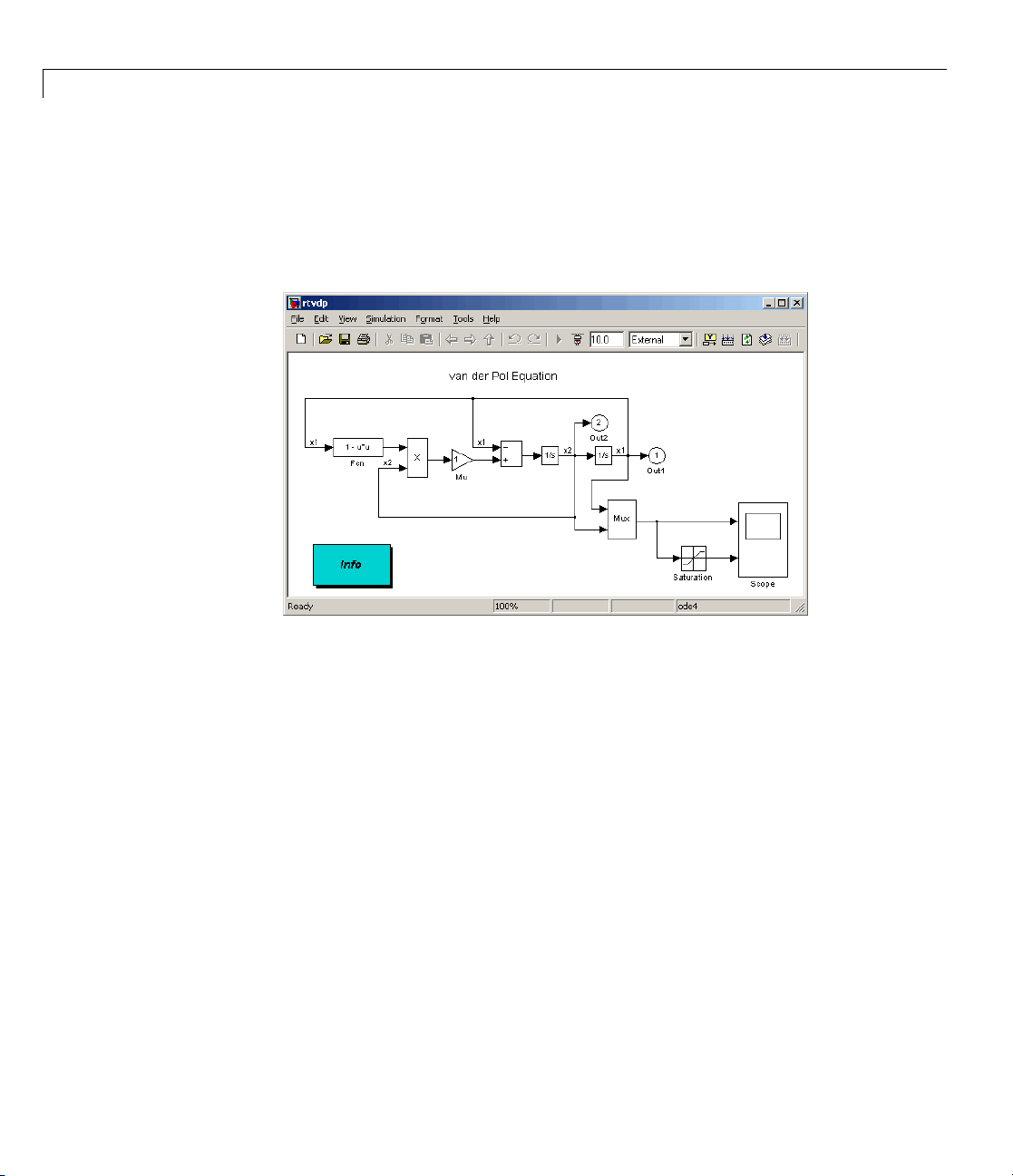
Running the Model rtvdp.mdl
The model rtvdp.mdl does not have any I/O blocks, so that you can run this
model regardless of the I/O boards in your computer. Running this model
will test the installation by running Real-Time Workshop code generation
software, Real-Time Windows Target software, and the Real-Time Windows
Target kernel.
After you have installed the Real-Time Windows Target kernel, you can test
the entire installation by building and running a real-time application. The
Real-Time Windows Target software includes the model
already has the correct Real-Time Workshop options selected for you:
rtvdp.mdl,which
2-17
2 Installation and Configuration
1 In the MATLAB Command Window, type
rtvdp
The Simulink model rtvdp.mdl window opens.
2-18
2 From the Tools menu, choose Real-Time Workshop > Build Model.
The MATLAB Command Window displays the following messages:
### Starting Real-Time Workshop build for model: rtvdp
### Invoking Target Language Compiler on rtvdp.rtw
...
### Compiling rtvdp.c
...
### Created Real-Time Windows Target module rtvdp.rwd.
### Successful completion of Real-Time Workshop build procedure
for model: rtvdp
3 From the Simulation menu, click External,andthenclickConnect to
target.
The M ATLA B Command Window displays the following message:
Model rtvdp loaded

Testing the Installation
4 From Simulation menu, click Start Real-Time Code.
The Scope window displays the output signals. If your Scope window looks
like the next figure, you have successfully installed the Real-Time Windows
Target software and have run a real-time application.
5 From Simulation menu, click Stop Real-Time Code.
The real-time application stops running, and the Scope window stops
displaying the output signals.
Displaying Status Information
The Real-Time Windows Target software provides the command rtwho for
displaying the kernel version number, followed by perform ance, timeslice,
and other information. To see this information, in the MATLAB Command
Window type
rtwho
The command dis plays several lines of information in the MATLAB Command
Window. Some possible lines and their interpretations are:
2-19

2 Installation and Configuration
This message indicates that the MATLAB environment and other
non-real-time applications (for example, a word processor) are able to run at
100% perform ance because no real-time applications are currently executing.
When a real-time application is executing, the MATLAB performance is at
a value below 100%. For example, if the MATLAB performance = 90.0%,
then the real-time application is using 10% of the CPU time. We recommend
that you select a sample rate so that
of at least 80%.
The kernel time slice period is the current frequency of the hardware timer
interrupt. One millisecond is the maximum value for models with large
sample times (slow sampling rate) or when an application has not been built.
This value changes when you select sampling ti mes less than 1 millisecond.
MATLAB performance = 100.0%
rtwho returns a MATLAB performance
Kernel timeslice period = 1 ms
TIMERS: Number Period Running
10.01Yes
2-20
The indicated timer(s) exist on your system with the period and run status
shown for each timer.
DRIVERS: Name Address Parameters
Humusoft AD512 0x300 []
ecg 0 []
The indicated device driver(s) are installed on your system at the address and
with the parameter(s) shown for each driver.
Detecting Excessive Sample Rates
If your specified sample r a t e is too fast, the Real-Time Windows Target
software detects and reports this during real-time execution. Sampling rates
exceeding 10 kHz can be achieved on Pentium computers. Once the model
is running, you can issue the
Window to observe the system performance.
For example, the following lines show that MATLAB performance has
decreased because the system is overloaded:
rtwho command in the MATLAB Command

Testing the Installation
MATLAB performance = 77.1%
Kernel timeslice period = 0.0 01 ms
We recommend that MATLAB performance not fall below 80%.
Demo Librar y
The demo library includes models with preset values and dialog boxes. These
models include a configuration of examples that use no I/O, A/D only, A/D and
D/A in a simple signal processing demo, as well as in a simple control demo.
Examples that use I/O blocks require you to configure the Adapter block to
match the I/O board installed in your computer. To see these demo models
from the MATLAB environment:
1 Type rtwtdemo in the MATLAB Command Window.
The Real-Time Windows Target Demos window displays.
2 From the list, select the demo to open it.
2-21

2 Installation and Configuration
2-22

Basic Procedures
• “Using Simulink Models” on page 3-2
• “Using Real-Time Applications” on page 3-14
• “Logging Signals to the Base Workspace” on page 3-27
• “Logging Signals to a Disk Drive” on page 3-34
• “Tuning Parameters” on page 3-44
3

3 Basic Procedures
Using Simulink Models
In this section...
“About Simulink Models” on page 3-2
“Creating a Model” on page 3-2
“Configuring a Model” on page 3-6
“Running a Simulation” on page 3-12
About Simulink Models
A Simulink model is a graphical representation of your physical system. You
create a Simulink model for a non-real-time simulation of your system, and
then you use the Simulink model to create a real-time application.
Creating a Model
You need to create a Simulink model before you can run a simulation or
create a real-time application. This procedure explains how to create a
simple Simulink model. You can use this model as an example to learn other
procedures that are useful with Real-Time Windows Target software.
3-2
1 In the MATLAB Command Window, type
simulink
The Simulink Library Browser opens. The left pane shows a hierarchy of
libraries and block categories, with the Simulink library at the top. The
right pane shows the b lock s available in the category selected on the left .
See “Library Browser” for more information.
2 Choose File>New>Model,orclicktheNew model buttononthetoolbar.
mpty Simulink window opens:
An e

Using Simulink®Models
3 In the left pane of the Simulink Library Browser window, select Simulink
>Sources. Click and drag a Signal Generator block from the browser to
the Simulink window.
Select Continuous. Click and drag a Transfer Fcn block to the Simulink
window.
Select Sinks. Click and drag a Scope block to the Simu link window.
4 Connect the Signal Generator output to the Transfer Fcn input by
clicking-and-dragging a line between the blocks. Likewise, connect the
Transfer Fcn output to the Scope input.
5 Double-click the Transfer Fcn block. The Block Parameters dialog box
opens. In the Numerator te xt box, enter:
[10000]
In the Denominator text box, enter
[1 70 10000]
Your Block Parameters dialog box looks similar to the next figure.
3-3

3 Basic Procedures
3-4
6 Click OK.
7 Double-click the Signal Generator block. The Block Parameters dialog box
opens. From the Wave form list, select
square.
In the Amplitude text box, enter
1
In the Frequency text box, enter
20
From the Units list, select rad/sec.
Your Block Parameters dialog box looks similar to the next figure.

Using Simulink®Models
8 Click OK.
The next figure shows the completed Simulink block diagram, with toolbar
and status bar not shown:
9 From the File menu, click Save As. The Save As dialog box opens. In the
File name textbox,enterafilenameforyourSimulinkmodelandclick
Save. For example, type
in_model
rtw
The Simulink software saves your model in the file rtwin_model.mdl.
To specify a default Real-Time Windows Target configuration set for your
model, see “Specifying the D efault Configuration Set” on page 3-7. If you
3-5

3 Basic Procedures
activate this configuration set for your model, you can build your real-time
application later without setting additional configuration parameters.
To manually configure your model, continue to “Entering Configuration
Parameters M anually” on page 3-8, following. That section teaches you how
to enter configuration parameters for your Simulink model, then leads you
into procedures for entering scope parameters and running a non-real-time
simulation of the model.
Model Referencing
The Real-Time Windows Target software supports model re fere ncing.
See “Referencing a Model” in the Simulink User’s Guide guide for more
information.
File System Input/Output
Like mos t real-time environments, the Real-Time Windows Target software
does not include a file system. Therefore, a Simulink model intended for use
in a Real-Time Windows Target application cannot use any blocks, such as the
To File or From File block, that generate file I/O calls such as
fopen or printf.
3-6
If a Real-Time Windows Target model contains any block that tries to perform
file system I/O, an error could occur when you try to compile the model,
generate code for it, or use External Mode with it. Even if no error occurs, the
block has no effect on either simulation or code execution.
To log signal data w ithout needing a file system, use the techniques described
in “Logging Signals to a Disk Drive” on page 3-34. See “Running a Real-Time
Application” on page 3-23 for information about using External Mode to
execute a Real-Time Windows Target application.
Configuring a Model
After you create a Simulink model, you can enter configuration parameters
for the model. These parameters control many properties of the model
for simulation and code generation. This section contains the essential
information you need when setting configuration parameters for a Real-Time
Windows Target application. For complete information about Simulink

Using Simulink®Models
configuration parameters, see “Setting Up Configuration Sets” and
“Configuration Parameters Dialog Box”.
A configuration set is a named set of values for model parameters, such as
solver type and simulation start or stop time. Every new model is created
with a default configuration set, called
Configuration, that initially specifies
default values for the model’s model parameters. You can subsequently cre ate
additional configuration sets and associate them with the model, as described
in “Referencing Config uration Sets”.
Theeasiestwaytospecifyconfiguration parameters for a Real-Time Windows
Target m odel is to programmatically assign the default Real-Time Windows
Target configuration set, as described in “Specifying the Default Configuration
Set” on page 3-7. You can also set parameters manually, as described in
“Entering Configuration Parameters Manually” on page 3-8. Other sections
describe setting configuration patterns for specific purposes.
Specifying the Default Configuration Set
After you create a Simulink model, you can use the rtwinconfigset function
to specify a default Real-Time Windows Target configuration set for the
model. In most cases, using
parameter values that the model needs. The following procedure uses the
Simulink model
rtwin_model.mdl as an exa m ple and assumes you have
already loade d that m odel (see “Creating a Model” on page 3-2):
rtwinconfigset provides all the configuration
1 If you have not already saved the model, from the File menu, click Save
As. The Save As dialog box opens. In the File name text box, enter a file
name for your Sim ulink model and click Save. For example, type
rtwin_model
The Simulink software saves your model in the file rtwin_model.mdl.
2 In the MATLAB Command Window, type
rtwinconfigset('rtwin_model')
The default Real-Time Windows Target configuration set, R T Win, is now
active for the
rtwin_model model. (Alternatively, you can set the default
Real-Time Windows Target configuration set by setting the Configuration
3-7

3 Basic Procedures
Parameters System target file option to rtwin.tlc.) You do not need
to perform any other configuration for a Real-Time Windows Target
application.
3 Save the model.
See “Creating a Real-Time Application” on page 3-19 for a description of how
to build your Real-Time Windows Target application .
To revert to the default configuration set, Configuration, or any other
configuration set you have for the model, use Model Explorer. This is an
alternative tool that you can use to enter simulation parameters for a model.
See the Simulink documentation for a description of how to use Model
Explorer.
Note Your model uses a Real -Time Windows Target configuration set when
you change the System target file value to a Real-Time Windows Target
one, such as
rtwin.tlc or rtwinert.tlc. The softw are creates the Real-Time
Windows Target configuration set, RTWin or RTWinERT, only i f one does
not already exist.
3-8
Entering Configuration Parameters Manually
The configuration parameters give information to Simulink softw a r e
for running a simulation. This procedure uses the Simulink model
rtwin_model.mdl as an example and assumes you have already l oa ded t ha t
model:
1 In the Simulink window, and from the Simulation menu, click
Configuration Parameters. In the Configuration Parameters dialog
box, click the Solver tab.
The Solver pane opens.
2 In the Start time field, enter 0.0.IntheStop time field, enter the amount
of time you want your model to run. For example, enter
3 From the Type list, choose Fixed-ste p. Real-Time Workshop code
generation software does not support variable step solvers.
10.0 seconds.

Using Simulink®Models
4 From the Solver list, choose a solver. For example, choos e the general
purpose solver
5 In the Fixedstepsizefield, enter a sample time. For example, enter
0.001 seconds for a sam p l e rate of 1000 samples/second.
6 From the Tasking Mode list, choose SingleTasking. (For models with
blocks that have diffe rent sample times, choose
ode5 (Dormand-Prince).
MultiTasking.)
Your Solver pane looks similar to the next figure.
7 Do one
• Clic
• Clic
of the follo wing:
k Apply to apply the changes to your model and leave the dialog
pen.
box o
k OK to apply the changes to your model and close the dialog box.
Entering Scope Parameters for Signal Tracing
enter o r change scope parameters to specify the x-axis and y-axis in a
You
ope w indow. Other properties include the number of graphs in one Scope
Sc
ndow and the sample time for models with discrete blocks.
wi
3-9

3 Basic Procedures
After you add a Scope block to your Simulink model, you can enter the scope
parameters for s ignal tracing:
1 In the Simulink window, doubl e- c li ck the Scope block.
A Scope window opens.
2 Click the Parameters button.
A Scope para
3 Click the General tab. In the Number of axes field, enter the number of
graphs you want in one Scope window. For example, enter
meters dialog box opens.
1 for a single
graph. Do not select the floating scope check box.
In the Time range field, enter the upper value for the time range. For
example, enter
From the S
Enterin
continu
Fixed st
g
ous time block. If you have discrete blocks in your model, enter the
ep size you entered in the Configuration Parameters dialog box.
1 second. From the Tick labels list, choose all.
ampling list, choose
0 indicates that the Simulink software evaluates this block as a
Sample time and enter 0 in the text box.
Your Scope parameters dialog box looks similar to the next figure.
3-10

Using Simulink®Models
4 Do one of the following:
• Click Apply to apply the changes to your model and leave the dialog
box open.
• Click OK to apply the changes to your model and close the dialog box.
5 In the Scope window, point to the y-axis shown in the next figure, and
right-click.
6 From the pop-up m enu, click Axes Properties.
7 The Scope properties: axis 1 dialog box opens. In the Y-min and Y-max
text boxes, enter the range for the y-axis in the Scope window. For example,
enter
-2 and 2 asshowninthenextfigure.
8 Do one of the following:
3-11

3 Basic Procedures
• Click Apply to apply the changes to your model and leave the dialog
box open.
• Click OK to apply the changes to your model and close the dialog box.
Running a Simulation
You use Simulink normal mode to run a non-real-time simulation. Running a
simulation lets you observe the behavior of your model in nonreal time.
After you load your Simulink model into the M ATLAB workspace, you can
run a simulation. This procedure uses the Simulink model
as an example and assumes you have loaded that model:
1 In the Simulink window, doubl e- c li ck the Scope block.
The Simulink software opens a Scope window with an empty graph.
2 From the Simulation menu:
• Select Normal mode simulation.
rtwin_model.mdl
3-12
• Choose Start to begin sim u lation .
The Simulink software runs the simulation and plots the signal data in
the Scope window.
During the simulation, the Scope window displays the samples for one
time range, increases the time offset, and then displays the samples for
thenexttimerange.

Using Simulink®Models
3 Do one of the following:
• Let the simulation run to the stop time.
• From the Simulation menu, click Stop.
The simulation stops. The MATLAB environment does not display any
messages.
3-13

3 Basic Procedures
Using Real-Time Applications
In this section...
“About Real-Time App lication s” on page 3-14
“Entering Simulation Parameters” on page 3-14
“Entering Scope Parameters for Signal Tracing” on page 3-17
“Creating a Real-Time Application” on page 3-19
“Entering A d dition a l Scope P ara m eters for Signal Tracing” on page 3-20
“Running a Real-Time Application” on page 3-23
“Running an Application from the Command Line” on page 3-25
About Real-Time Applications
You create a real-time application to let your system run while synchronized
to a real-time clock. This allows your system to control or interact with an
external system. This is necessary if you use your s ystem to stabilize a
physical plant. The first step is to create a Simulink Model, as described in
the previous section, “Using Simulink Models” on page 3-2.
3-14
Entering Simulation Parameters
After you create a Simulink model, you can enter simulation parameters for
use by Real-Time Workshop code generation software for creating C code
and building a real-time application.
This procedure uses the Simulink model
assumes you have already loaded that model:
1 In the Simulink window, and from the Simulation menu, click
Configuration Parameters.
2 Click the Real-Time Workshop node.
e Real-Time Workshop pane opens.
Th
rtwin_model.mdl as an example and

Using Real-Time Applications
3 In the Target selection section, click the Browse button at the RTW
system target file list.
The System Target File Browser opens.
4 Select the system target file for building a Real-Time Windows Target
application, and click OK.
The dialog a
template ma
Real-Time W
utomatically enters the system target file
kefile
rtwin.tmf,andthemakecommandmake_rtw into the
orkshop pane.
If you have the Real-Time Workshop
®
Embedded Coder™ product, you can
rtwin.tlc,the
build a n ERT target application. To build an ERT target application, in the
Target selection section, click the Browse button at the System target
file list. Click
rtwinert.tlc,andthenclickOK.
Although not visible in the Real-Time Workshop pane, when you click
OK you also configure the external target interface MEX file
rtwinext.
This allows external mode to pass new parameters to the real-time
application and to return signal data from the real-time application. The
data is displayed in Scope blocks or saved with signal logging.
Your Re
al-Time Workshop pane looks similar to the next figure.
3-15

3 Basic Procedures
Do not sel
paramete
of RAM or R
paramete
more mem
inline p
5 Click the Hardware Implementation node. The following values are
set by default:
• Device vendor —
• Device type — 32-bit x86 compatible
• Emulation hardware — N one
ect Inline param eters on the Optimization node. Inlining
rs is used for custom targets when you want to reduce the amount
OM with embedded systems. Also, if you select inlining
rs, you disable the parameter tuning feature. Since PCs have
ory than embedded systems, we recommend that you do not
arameters.
Generic
3-16

Using Real-Time Applications
6 Do one of the
• Click Appl
box open.
• Click OK t
Entering
You ente
Scope wi
window a
If you e
proced
After
param
1 In th
2 Click the Parameters button.
r or change scope parameters to format the x -axis and y-axis in a
ndow. Other parameters include the number of graphs in a one Scope
nd whether the scope is connected to a continuous or discrete model.
ntered the scope parameters for running a simulation, you can skip this
ure. This information is repeated here if you did n ot run a simulation.
you add a Scope block to your Simulink model, you can enter the scope
eters for signal tracing:
e Simulink window, double-click the Scope block.
A Scope window opens.
following:
y to apply the changes to your model and leave the dialog
o apply the changes to your model and close the dialog box.
Scope Parameters for Signal Tracing
3-17

3 Basic Procedures
A Scope paramete
3 Click the General tab. In the Number of axes field, enter the number of
graphs you want in one Scope window. For example, enter
rs dialog box opens.
1 for a single
graph. Do not select the floating scope check box.
In the Time range field, enter the upper value for the time range. For
example, enter
From the Sam
Entering
continuous
Fixed step
1 second. From the Tick labels list, choose all.
pling list, choose Sample time and enter
ndicates that the Simulink software evaluates this block as a
0 i
0 in the text box.
time block. If you have discrete blocks in your model, enter the
size you entered in the Configuration Parameters dialog box.
Your Scope parameters dialog box looks similar to the next figure.
3-18
4 Do one of the following:
• Click Apply to apply the changes to your model and leave the dialog
box open.
• Click OK to apply the changes to your model and close the dialog box.

Using Real-Time Applications
5 In the Scope window, point to the y-axis and right-click. From the menu,
click Axes Properties.
The Scope properties: axis 1 dialog box opens.
6 In the Y-min and Y-max text boxes enter the range for the y-axis in the
Scope window. Forexample,enter
7 Do one of the following:
-2 and 2.
• Click Apply to apply the changes to your model and leave the dialog
box open.
• Click OK to apply the changes to your model and close the dialog box.
Creating a Real-Time Application
The Real-Time Workshop code generation softw are creates C code from your
Simulink model, th en the Open Watcom C/C++ compiler compiles and links
that C code into a real-time application.
After you enter parameters into the Configuration Parameters dialog box
for use by the Real-Time Workshop code generation software, you can
build a real-time application. This procedure uses the Simulink model
rtwin_model.mdl as an example, and assum es you have loaded that model:
1 In the Simulin k window, from the Tools menu, point to Real-Time
Workshop,andthenclickBuild Model.
build process does the following:
The
• The
Real-Time Workshop code generation software creates the C code
sou
rce files
rtwin_model.c and rtwin_mo del. h.
3-19

3 Basic Procedures
• Themakeutilitymake_rtw.exe creates the makefile rtwin_model.mk
from the template makefile rtwin.tmf.
• Themakeutility
rtwin_model.rwd using the makefile rtwin_model.mk created above.
The file
real-time application. You can run the real-time application with the
Real-Time Windows Target kernel.
2 Connect your Simulink model to your real-time application. See “Entering
Additional Scope Parameters for Signal Tracing” on page 3-20.
After you create a real-time application, you can exit the MATLAB
environment, start the MATLAB environment again, and then connect and
run the executable without having to rebuild.
rtwin_model.rwd is a binary file that we refer to as your
make_rtw.exe builds the real-time application
Entering Additional Scope Parameters for Signal
Tracing
Simulink external mode connects your Simulink model to your real-time
application. This connection allows you to use the Simulink block diagram as
a graphical user interface to your real-time application.
After you have created a real-time application, you can enter scope parameters
for signal tracing with Simulink external mode:
1 In the Simulation window, and from the Simulation menu, click
Configuration Parameters.
3-20
2 Select the Real-Time Windows Target node.
The Real-Time Windows Target pane opens.
3 Select the External mode check box.
The MEX-file name label s hould have an entry of
rtwinext.mex* is supplied with the Real-Time Windows Target software
to work with Simulink external mode and support uploading s ignal data
and downloading parameter values.
The Real-Time Windows Target pane should appear as follows.
rtwinext.TheMEX-file

Using Real-Time Applications
4 Click OK.
5 In the Sim
Mode Con
ulation window, and from the Tools menu, click External
trol Panel.
The External Mode Control Panel dialog box opens.
3-21

3 Basic Procedures
6 Click the Signal & Triggering button.
3-22
The Exter
7 Select the Select all check box. From the Source list, choose manual.
nal Signal & Triggering dialog box opens.
From the Mode list, choose normal.
The
X under Signal selection indicates that a signal is tagged for data
collection, and
8 In the D
For exa
time o
9 Sele
mple, to specify a sample rate of 1000 samples/second and a stop
f 10 se conds, enter
10001
ct the Armwhenconnectingtotargetcheck box.
T indicates that the signal is tagged a s a trigger signal.
uration field, enter the number of sample points in a data buffer.
If you do not select this check box, data is not displayed in the Scope
window.
The External Signal & Triggering dialog box looks like this:

10 Do one of the following:
Using Real-Time Applications
• Click Apply to apply the changes to your model and leave the dialog
box open.
• Click Close to apply the changes to your model and close the dialog box.
You must click the Apply or Close button on the External Signal &
Triggering dialog box for the changes you made to take effect. Generally it
is no t necessary to rebuild your re al-tim e application.
Running a Real-Time Application
You run your real-time application to observe the behavior of your model in
real tim e with the generated code. The process of connecting co n sists of
• Establishing a connection between your Simulink model and the kernel to
allow exchange of commands, parameters, and logged data.
• Running the application in real time.
After you build the real-time application, you can run your model in real time.
This procedure uses the Simulink model
and assumes you have created a real-time application for that m odel:
rtwin_model.mdl as an example,
3-23

3 Basic Procedures
1 From the Simulation menu:
• Select External mode simulation.
• Choose Connect To Target.
(You can conne
The MATLAB Command Window displays the message
Model rtwin_model loaded
2 From the Simulation menu, choose Start Real-Time Code.
(You can also start the code from the toolbar by clicking
The Simulink software runs the execution and plots the signal data in
the Scope window.
In this example, the Scope window displays 1000 samples in 1 second,
increases the time offset, and then displaysthesamplesforthenext1
second.
Note Transfer of data is less critical than calculating the signal outputs
at the selected sample interval. Therefore, data transfer runs at a
lower priority in the remaining CPU time after real-time applicat ion
computations are performed while waiting for another interrupt to trigger
the next real-time application update. The result may be a loss of data
points displayed in the Scope window.
ct to the target from the toolbar by clicking
).
).
3-24

3 Do one of the following:
• Let the execution run until it reaches the stop time.
• From the Simulation menu, click Stop Real-time Code.
The real-time application stops.
Using Real-Time Applications
4 In the Sim
Disconne
5 From the Simulation menu, click External.
ulation window, and from the Simulation menu, click
ct From Target.
The MATLAB Command Window displays the message
Model r
twin_model unloaded
Running an Application from the Command Line
YoucanusetheMATLABcommand-lineinterfaceasanalternativetousing
the Simulink GUI. Enter commands directly in the MATLAB Command
Window or save them in a script file.
After you build the real-time application, you can run your model in real time.
This procedure uses the Simulink model
and assumes you have created a real-time application for that m odel:
1 In the MATLAB Command Window, type
rtwin_model.mdl as an example,
3-25

3 Basic Procedures
set_param(gcs,'SimulationMode','external')
The Simulink software changes to external mode.
2 Type
set_param(gcs,'SimulationCommand','connect')
The MATLAB environment loads the real-time application, connects it to
the Simulink block diagram, and displays the message
Model rtwin_model loaded
3 Type
set_param(gcs,'SimulationCommand','start')
The Simulink software starts running the real-time application.
4 Type
3-26
set_param(gcs,'SimulationCommand','stop')
The Simulink software stops the real-time application.

Logging Signals to the Base Workspace
In this section...
“About Signal Logging” on page 3-27
“Entering Scope Parameters” on page 3-27
“Entering Signal and Triggering Properties” on pag e 3-29
“Plotting Logged Signal Data” on page 3-31
About Signal Logging
Signal logging to the base workspace is the process of saving (logging) data
to a variable in your MATLAB w orkspace. This allows you to use MATLAB
functions for data analysis and MATLAB plotting functions for visualization.
You can save data to a variable during a simulation or during an execution.
Simulink external mode does not support data logging with Outport blocks in
your Simulink model. This means you do not enter or select parameters on
the Data I/O tab in the Configu rati o n Parameters dialog bo x.
Logging Signals to the Base Workspace
To use signal logging with a Real-Time Windows Target application, you must
add a Scope block to your Simulink model.
Entering Scope Parameters
Data is saved to the MATLAB workspace through a Simulink Scope block.
Scope block parameters need to be set for data to be saved. After you create a
Simulink model and add a Scope block, you can enter the scope parameters
for signal logging to the MATLAB workspace. This procedure uses the
Simulink model
already loaded that model.
Note If you entered the scope parameters for running a simulation, you may
want to look ov er this pro cedure, because the Scope paramete rs dialog box is
related to the External Signal and Triggering dialog box.
rtwin_model.mdl as an example, and assumes you have
3-27

3 Basic Procedures
1 In the Simulink window, doubl e- c li ck the Scope block.
A Scope window opens.
2 On the toolbar, click Parameters.
A Scope Parameters dialog box opens.
3 Click the Data history tab.
4 Do one of the following:
• If you a re running a simulation, select the Limitdatapointstolast
check box, and enter the number of sample points to save.
• If you are running an execution, do not select the Limit data points to
last check box.
3-28
The Limit data points to last check box is related to the Duration
value in t he External S ig nal and Trig g ering dialog box. The smaller of
either value limits the number of sample points saved to the MATLAB
workspace. Wh en you are using Real-Time Windows Target software, use
the Duration valuetosetthenumberofsamplepointsyousave. Toset
the Duration value, see the next section.
5 Select the Save data to workspace check box. In the Variable name
text box, enter the name of a MATLAB variable. The default name is
ScopeData.
6 From the Format list, choose Structure with time, Structure,orArray
(compatible w ith V2.0-2.2). For example, to save the sample times and
signal values at those times, choose
Structure with time.
Your Data history pane looks similar to the next figure.

Logging Signals to the Base Workspace
7 Do one of the following:
• Click Apply to apply the changes to your model and leave the dialog
box open.
• Click OK to apply the changes to your model and close the dialog box.
When you modify anything in the Scope parameters dialog box, you must
click the Apply or OK button for the changes to take effect, and you must
rebuild your real-time application before connecting and starting it. If you
do not rebuild, an error dialog box will open. If you do not click Apply,your
executable will run, but it will use the old settings.
The rea
includ
model c
realafter
Ente
Data
Sign
area
cedure.
pro
er y ou create a Simulink model and add a Scope block, you can enter the
Aft
gnal and triggering properties for logging to the MATLAB workspace. This
si
son why you need to rebuild is because the model checksum
es settings from the Scope block used for signal logging. If the
hecksum does not match the checksum in the generated code, the
time application cannot run. Always rebuild your real-time application
changing Scope parameters.
ring Signal and Triggering Properties
is saved to the MATLAB workspace through a Simulink Scope block.
al and triggering properties need to be set only when you are running
l-time application. If you are running a simulation, you can skip this
3-29

3 Basic Procedures
procedure uses the Simulink model rtwin_model.mdl as an example and
assumes you have already loaded that model:
1 In the Simulink window, and from the Tools menu, click External Mode
Control Panel.
The External Mode Control Panel dialog box opens.
2 Click the Signal & Triggering button.
The E xternal Signal & Triggering dialog box opens.
3 Click the Select all button. From the Source list, choosemanual.From
the
Mode list, choose normal.
The
X under Signal selection designates that a signal has been tagged
for data collection, and
T designates that the signal has been tagged as
atriggersignal.
4 In the Duration field, enter the number of sample points in a data buffer.
For example, if you have a sample rate of 1000 samples/second and a stop
time of 10 seconds, you could enter
3-30
10000
The Duration value is related to the Limit data points to last value in
the Scope parameters dialog box. The smaller of either value limits the
number of sample points saved to the MATLA B workspace. We recomm end
that you do not select the Limit data points to last check box; use the
Duration valuetosetthenumberofsamplepointssaved. Toclearthe
Limit data points to last check box, see “Entering Scope Parameters”
on page 3-27.
The Duration valuespecifiesthenumberofcontiguous points of data to be
collected in each buffer of data. W e recommend that you enter a Duration
value equal to the total number of sample points that you need to collect
rather than relying on a series of buffers to be continuous.
If you e nter a value less than the total number of sample points, you
will lose sample points during the time needed to transfer values from
thedatabuffertotheMATLABworkspace. TheReal-TimeWindows

Logging Signals to the Base Workspace
Target software ensures that points are continuous only within one buffer.
Between buffers, because of transfer tim e, some samples will be omitted.
We also recommend setting the time axis for Simulink Scope blocks equal
to the sample interval (in seconds) times the number of points in each
data buffer. This setting will display one buffer of data across the entire
Simulink Scope plot.
The External Signal & Triggering dialog box looks similar to the next figure.
5 Do one of the following:
• Click Apply to apply the changes to your model and leave the dialog
box open.
• Click Close to apply the changes to your model and close the dialog box.
You must click the Apply or Close button on the External Signal &
Triggering dialog box for the changes you made to take effect. Generally it
is no t necessary to rebuild your re al-tim e application.
Plotting Logged Signal Data
You can use the M ATLAB plotting functions for visualizing non-real-time
simulated data or real-time application data.
3-31

3 Basic Procedures
After running your real-time application and logging data to the M ATLAB
workspace, you can plot the data. This procedure uses the Simulink model
rtwin_model.mdl as an example, and assumes you saved your data to the
variable
1 In the MATLAB Command Window, type
ScopeData.
ScopeData
The MATLAB Command Window shows the structure of the variable
ScopeData.ThevariableScopeData is a MATLAB structure containing
fields for the time vector, signal structure, and a string containing the
block name.
ScopeData =
time: [10000x1 double]
signals: [1x1 struct]
blockName: 'rtwin_model/Scope'
To list the contents of the structure signals, type
3-32
ScopeData.signals
The MATLAB Command Window shows the structure of the variable
ScopeData.signals. This structure contains one or more vectors of signal
data depending on the number of signal inputs to the Scope block.
ans =
values: [10000x1 double]
dimensions: 1
label: ''
title: []
plotStyle: 1
2 To plot the first 1000 points, type
plot(ScopeData.time(1:1000),ScopeData.signals.values(1:1000))
The MATLAB environment plots the first 1000 samples from 0.0000 to
0.9990 second.
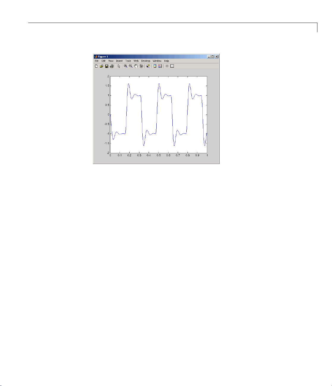
Logging Signals to the Base Workspace
3 The variable ScopeDa ta is not automatically saved to your hard disk. To
save the variable
ScopeData,type
save ScopeData
The MATLAB environment saves the scope data to the file Sc opeD ata.mat.
3-33

3 Basic Procedures
Logging Signals to a Disk Drive
In this section...
“About Signal Logging” on page 3-34
“Entering Scope Parameters” on page 3-34
“Entering Signal and Triggering Properties” on pag e 3-37
“Entering Data Archiving Parameters” on page 3-39
“Plotting Logged Signal Data” on page 3-41
About Signal Logging
Logging signals to a disk drive is th e process of saving (logging) data to a
variable in your MATLAB workspace and then saving that data to a MAT-file
on your disk drive. This allows you to use MATLAB functions for data
analysis and MATLAB plotting functions for visualization.
3-34
Using the data archiving feature p r ovided in the External Mode Control
Panel, you can save data to a file during execution. Simulink external mode
does not support data logging with Outport blocks in your Simulink model.
This means you do not enter or select parameters on the Data I/O pane in the
Configuration Parameters dialog box.
To use the data archiving feature with a Real-Time W in d ows Target
application, you must add a Scope block to your Simulink model, and you
mustexecuteareal-timeapplication.
Entering Scope Parameters
YousavedatatoadiskdrivebyfirstsavingthedatatotheMATLAB
workspace through a Simulink Scope block. You need to set scope block
parameters for data to be saved.
After you create a Simulink model and add a Scope block, you can enter the
scope parameters for signal logging to a disk drive. This procedure uses the
Simulink model
already loaded that model.
rtwin_model.mdl as an example, and assumes you have
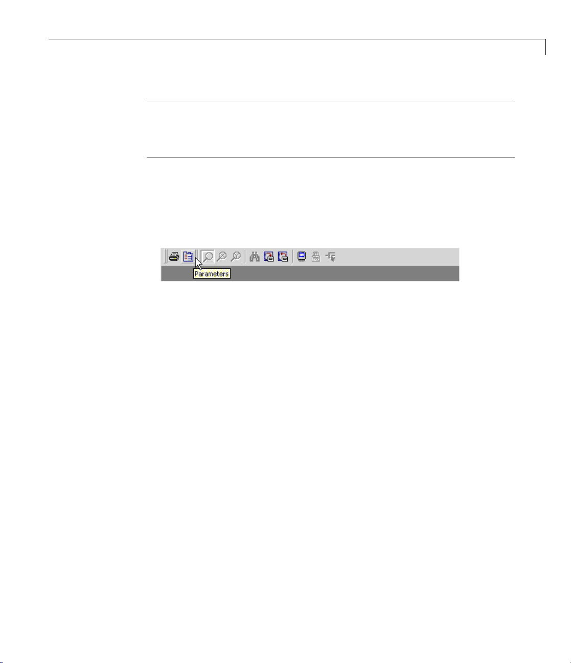
Logging Signals to a Disk Drive
Note If you entered the scope parameters for running a simulation, you
may want to look over this procedure, because the Scope parameters dialog
box is related to the External Signal & Triggering dialog box and the Data
Archiving dialog box.
1 In the Simulink window, doubl e- c li ck the Scope block.
A Scope window opens.
2 On the toolbar, click the Parameters button.
A Scope parameters dialog box opens.
3 Click the
4 Do one of the following:
Data history tab.
• If you are running a simulation, you can select the Limit data points
to last check box, and enter the number of sample points to save.
• If you are running an execution, do not select the Limit data points to
last check box.
The Limit data points to last check box is related to the Duration value
in the External Signal & Triggering dialog box. The smaller of either value
limits the number of sample points saved to the MA TLAB workspace.
When using Real-Time Window s Target software, we recommend that you
use the Duration valuetosetthenumberofsamplepointsyousave. To
set the Duration value, see “Entering Signal and Triggering Properties”
on page 3-37.
ect the Save data to workspace check b ox. In the Variable name
5 Sel
t box, enter the name of a MATLAB variable. The default name is
tex
Sco
peData
.
3-35

3 Basic Procedures
The Scope parameters dialog box is related to the Data Archiving dialog
box. In the Scope parameters dialog box, you must select the Save data
to workspace check box to be able to save data to a disk drive, for two
reasons:
• The data is first transferred f rom the data buffer to the M ATLA B
workspace before being written to a MAT-file.
• The Variable name entered in the Scope parameters dialog box is the
same as the one in the MATLAB workspace and the MAT-file.
If you do not select the Save data to workspace check box, the MAT-files
for data logging will be created, but they w ill be e mpty .
6 From the Format list, c hoose eitherStructure with time, Structure,or
Array(compatible with Version 2.0 through Version 2.2). For example, to
save the sample times and signal values at those times, choose
with time
.YourData history pane looks similar to the next figure.
Structure
3-36
7 Do one of the following:
• Click Apply to apply the changes to your model and leave the dialog
box open.
• Click OK to apply the changes to your model and close the dialog box.

Logging Signals to a Disk Drive
You must rebuild your real-time application before connecting and starting
the application with changed settings. If you do not rebuild after making
changes, an error will occur.
Entering Signal and Triggering Properties
Data is saved to a disk drive by first saving the data to the MATLAB
workspace through a Simulink Scope block. Signal and triggering properties
need to be set when running a real-time application.
After you create a Simulink model and add a Scope block, you can enter
the signal and triggering properties fordataloggingtoadiskdrive. This
procedure uses the Simulink model
assumes you have already loaded that model:
1 In the Simulink window, and from the Tools menu, click External Mode
Control Panel.
The External Mode Control Panel dialog box opens.
rtwin_model.mdl as an example, and
2 Click the Signal & Triggering button.
The E xternal Signal & Triggering dialog box opens.
3 Click the Select all button. From the Source list, choosemanual.From
the
Mode list, choose normal.
The
X under Signal selection designates that a signal has been tagged
for data collection, and
T designates that the signal has been tagged as
atriggersignal.
4 In the Duration field, enter the number of sample points in a data buffer.
For example, if you have a sample rate of 1000 samples/second and a stop
time of 10 seconds, then enter
10000
The Duration value is related to the Limit data points to last value in
the Scope parameters dialog box. The smaller of either value limits the
number of sample points saved to the MATLA B workspace. We recomm end
that you do not select the Limit data points to last check box, and use
the Duration valuetosetthenumberofsamplepointssaved.
3-37

3 Basic Procedures
The Duration valuespecifiesthenumberofcontiguous points of data to be
collected in each buffer of data. W e recommend that you enter a Duration
value equal to the total number of sample points you need to collect for a
run. If you enter a value much less than the total number of sample points,
you may lose logging sample points due to the time needed to transfer
values from the data buffer to the MATLAB workspace.
We also recommend setting the time axis for Simulink Scope blocks equal
to the sample interval (in seconds) times the number of points in each
data buffer. This setting will display one buffer of data across the entire
Simulink Scope plot.
The External Signal & Triggering dialog box looks similar to the next figure.
3-38
5 Do one of the following:
• Click Apply to apply the changes to your model and leave the dialog
box open.
• Click Close to apply the changes to your model and close the dialog box.
You must click the Apply or Close button on the External Signal &
Triggeringdialogboxforthechangesyoumadetotakeeffect,butyoudo
not have to rebuild your real-time application.

Logging Signals to a Disk Drive
Entering Data Ar
The Data Archivi
box. In the Scope
workspace chec
• The data is fir
workspace bef
• The Variable n
same as the on
thedatatobe
parameter t
If you do not
parameters
they will b
After you c
Paramete
1 In the Sim
Mode Con
The External Mode Control Panel dialog box opens:
eempty.
rsfordataloggingtoadiskdrive:
ng dialog box is related to the Scope parameters dialog
k box to be able to save data to a disk drive, for two reasons:
st transferred from the scope data buffer to the MATLAB
ore being written to a MAT-file.
eintheMATLABworkspaceandtheMAT-file. Enabling
saved enables a variable named with the Variable name
obesavedtoaMAT-file.
select the Save data to workspace check box in the Scope
dialog box, the MAT-files for data logging will be created, but
reate a Simulink model, you can enter the Data Archiving
ulation window, and from the Tools menu, click External
trol Panel.
chiving Parameters
parameters dialog box, you must select the Save data to
ame entered in the Scope parameters dialog box is the
3-39

3 Basic Procedures
2 Click the Data Archiving button.
3-40
The Exter
to specif
3 Select the Enable archiving check box.
4 In the Directory text box, enter the path to a directory on your disk drive.
For example, if your MATLAB working directory is named
c:\mwd
5 In the File text box, enter the file name prefix for the data files to be
nal Data Archiving dialog box opens. This dialog box allows you
y data a rchiving options.
mwd,enter
saved. For example, enter
data
The MATLAB environment names the files data_0.mat, data_1.mat,etc.
The number of files equals the total sample points. For example, if you set
Duration to
ect the Append file suffix to variable names check box.
6 Sel
Total sample points, then only one file is created.

Logging Signals to a Disk Drive
Within each MAT-file, a variable is saved with the same name you
entered in the Variable name text box (Data history pane on the
Scope parameters dialog box). By selecting the Append file suffix to
variable names check box, the same suffix that is added to the MAT-file
is added to the variable name. For example, if you entered the variable
name
ScopeData, then within the file data_0.mat will be a variable
ScopeData_0.
Your External Data Archiving dialog box looks similar to the next figure.
7 Click the Close button.
The parameters you entered are applied to your model.
There is no Apply button with this dialog box. You must click the Close
button for the changes you make to take effect.
Plotting Logged Signal Data
You can use the MATLAB plotting functions for visualization of your
non-real-time simulated data or your real-time executed data.
After running your real-time application and logging data to a disk drive, you
can plot the data. This procedure uses the Simulink model
as an example, and assumes you saved your data to the variable ScopeData:
1 In the MATLAB Command Window, type
ScopeData
rtwin_model.mdl
3-41

3 Basic Procedures
The MATLAB Command Window shows the structure of the variable
ScopeData.ThevariableScopeData is a MATLAB structure containing the
fields time vector, signal structure, and a string containing the block name.
ScopeData =
time: [10000x1 double]
signals: [1x1 struct]
blockName: 'rtwin_model/Scope'
2 To list the MAT-files saved to your disk drive , type
dir *.mat
The MATLAB Command Window shows the MAT-files in your current
working directory.
ScopeData.mat
3 To clear the MATLAB workspace and load the scope data, type
3-42
clear
load ScopeData
who
The MATLAB Command Window displays:
Your variables are:
ScopeData
4 To plot the first 1000 points, type
plot(ScopeData.time(1:1000), ScopeData_0.signals.values(1:1000))
The MATLAB environment plots the first 1000 samples from 0.0000 to
0.9990 second.

Logging Signals to a Disk Drive
3-43

3 Basic Procedures
Tuning Parameters
In this section...
“About Parameter Tuning” on page 3-44
“Changing M odel Parameters” on page 3-45
About Parameter Tuning
Simulink external mode connects your Simulink model to your real-time
application. The block diagram becomes a graphical user interface to the
real-time application You can change parameter values while running the
real-time application by changing the values in
• Block parameters — Change block parameters by changing the values
in the dia log bo xes associated with the Simulink blocks. Once you change
a value, and click OK, the new value is downloaded to the real-time
application.
3-44
Note Opening a dialog box for a source block causes Simulink to pause.
While Simulink is paused, you can edit the parameter val ues. You must
close the dialog box to have the changes take effect and allow Simulink
to continue.
• MATLAB variables — Change MATLAB v ariables by entering the
changes through the MATLAB command line, and then press Ctrl+D for
the changes to be downloaded to your executable. An alternative method to
download parameters is to click Update Diagram from the Edit menu
in your Simulink window. Simply changing the value of the MATLAB
variable at the MATLAB command line is not sufficient for the Simulink
software to know that the value has changed.
Simulink external mode also supports side-effects functions. For example,
given an expression in a Gain block of
the resulting value is exported to the real-time application during execution.
2*a+b, the expression is evaluated and

Tuning Parameters
When a parameter in a Simulink model is changed, the communication
module
rtwinext.mex* transfers the data to the external real-time
application and changes the model parameters. Only the parameters that do
not result in model structure modification can be changed. If the structure
is modified, you must recompile the model. Model structure changes are
detected automatically using model checksum and reported to the MATLAB
Command Window to avoid conflicts.
Changing Model Parameters
You must use Simulink external mode to change model parameters. While
external mode is running, you can open Simulink blocks and change
parameter values. External mode will transferthenewvaluetothereal-time
application.
Note Opening a dialog box for a source block causes Simulink to pause. While
Simulink is paused, you can edit the parameter values. You must close the
dialog box to have the chan g es take effect and allow Simulink to continue.
After you start running your real-time application, you can change para m eters
and observe the changes to the signals. To start a real-time application, see
“Running a Real-Time Application” on page 3-23.
The following procedure uses the Simulink model
rtwin_model.mdl as
an example. It assum es you have created a real-time application and are
executing it.
1 From the Simulation menu, click Start Real-Time.
The real-time execution starts running and signal data is displayed in
the Scope window.
3-45

3 Basic Procedures
2 From the Simulink block diagram, double-click the Transfer Function block.
The Block Parameters: Transfer Fcn dialog box opens:
3-46
3 In the Denominator field, change 70 to 30.ClickOK.

Tuning Parameters
The effect of changing a block parameter is shown in the Scope window.
3-47

3 Basic Procedures
3-48

4
Boards, Blocks, and Drivers
• “Introduction” on page 4-2
• “Using I/O Boards” on page 4-3
• “Using I/O Driver Blocks” on page 4-10
• “Using Analog I/O Drivers” on page 4-16
• “Using Vector CAN Dr ivers” on page 4-21

4 Boards, Blocks, and Drivers
Introduction
Real-Time W indo ws Target software includes driver blocks for more than 200
I/O boards. These driver blocks connect the physical world to your real-time
application.
4-2

Using I/O Boards
In this section...
“About I/O Boards” on page 4-3
“Installing and Configuring I/O Boards and Drivers” on page 4-3
“ISA Bus Board” on page 4-7
“PCI Bus Board” on page 4-7
“PC/104 Board” on page 4-8
“Compact PCI Board” on page 4-8
“PCMCIA Board” on page 4-9
About I/O Boards
Typically I/O boards are preset from the factory for certain base addresses,
voltage levels, and unipolar or bipolar modes of operation. Boards often
include switches or jumpers that allow you to change many of these initial
settings. For information about setting up and installing any I/O board, read
the board manufacturer’s documentation.
Using I/O Boards
For a n online list of all I/O boards that Real-Time Windows Target software
supports, see Supported I/O Boards.
Installing and Configuring I/O Boards and Drivers
A R eal-Time Windows Target model connects to a board by including an I/O
driver block. This block provides an interface to the board’s device driver and
all b oard-specific settings. The device drivers included with the Real-Time
Windows Target software usually provide the same flexibility of settings
offered by the board manufacturer. You can enter I/O board settings by using
the I/O Block Parameters dialog box; setting jumpers and switches on the
board; or both. The three types of board settings are:
• Software selectable — Specify the desired settings in the I/O Block
Parameters dialog box. The driver writes the settings you specify to the
board. Examples include A/D gain inputs and selecting unipolar or bipolar
D/A outputs.
4-3

4 Boards, Blocks, and Drivers
• Hardware selectable and software readable — Specify the desired
• Hardware selectable, but not software readable —Setjumpersor
You can configure a Real-Time Windows Target model to use an I/O board
whether or not the board exists in the computer, but you will not be able to run
the model u ntil th e board is installed with any jumpers or switches correctly
set. Details o f installation and configuration depend on the data transfer
direction and the specific board, but are essentially similar in all cases.
Details for various types of boards and drivers appear later in this chapter.
settings by configuring jumpers or switches on the board. The driver reads
the settings you selected and displays them in the I/O Block Parameters
dialog box.
switches on the physical board, and then enter the same settings in the I/O
Block Parameters dialog box. These entries must match the hardware
jumpers or switches you set on the board. This type of setting is necessary
when the board manufacturer does not provide a means for the I/O driver
to write or read all board settings. Examples include base address, D/A
gain, a nd differential or single-ended A/D inputs.
4-4
The following instructions use the Humusoft
®
AD512 I/O board as an example,
configure the board for analog input, and assume that you have physically
configured and installed the board in your computer before you add its driver
to your model. Cu stomize the steps t o provide the results that you need.
To install and configure an I/O board and its driver,
1 Install the board in the computer, setting any jumpers or switches as
needed.
2 In the model window, choose View > Library Browser to display the
Simulink Library Browser.
3 Clone an appropriate Input or Output driver block to your model from the
Real-Time Windows Target library.
4 Double-click the cloned I/O driver block.
The I/O Block Parameters dialog box opens. For an Analog Input block, the
dialog box initially looks like this:
 Loading...