

Page 1

Fuzzy Logic Toolbo
User’s Guide
x™ 2
Page 2

How to Contact The MathWorks
www.mathworks.
comp.soft-sys.matlab Newsgroup
www.mathworks.com/contact_TS.html Technical Support
suggest@mathworks.com Product enhancement suggestions
bugs@mathwo
doc@mathworks.com Documentation error reports
service@mathworks.com Order status, license renewals, passcodes
info@mathwo
com
rks.com
rks.com
Web
Bug reports
Sales, prici
ng, and general information
508-647-7000 (Phone)
508-647-7001 (Fax)
The MathWorks, Inc.
3 Apple Hill Drive
Natick, MA 01760-2098
For contact information about worldwide offices, see the MathWorks Web site.
Fuzzy Logic Toolbox™ User’s Guide
© COPY R IGHT 1995–2010 The MathW orks, Inc.
The software described in this document is furnished under a license agreement. The software may be used
or copied only under the terms of the license agreement. No part of this manual may be photocopied or
reproduced in any form without prior written consent from The MathW orks, Inc.
FEDERAL ACQUISITION: This provision applies to all acquisitions of the Program and Documentation
by, for, or through the federal government of the United States. By accepting delivery of the Program
or Documentation, the government hereby agrees that this s oftware or docume n tation qualifies as
commercial computer software or commercial computer software documentation as such terms are used
or defined in FAR 12.212, DFARS Part 227.72, and DFARS 252.227-7014. Accordingly, the terms and
conditions of this Agreement and only those rights specified in this Agreement, shall pertain to and govern
theuse,modification,reproduction,release,performance,display,anddisclosureoftheProgramand
Documentation by the federal government (or other entity acquiring for or through the federal government)
and shall supersede any conflicting contractual terms or conditions. If this License fails to meet the
government’s needs or is inconsistent in any respect with federal procurement law, the government agrees
to return the Program and Docu mentation, unused, to The MathWorks, Inc.
Trademarks
MATLAB and Simulink are registered trademarks of The MathWorks, Inc. See
www.mathworks.com/trademarks for a list of additional trademarks. Other product or brand
names may be trademarks or registered trademarks of their respective holders.
Patents
The MathWorks products are protected by one or more U.S. patents. Please see
www.mathworks.com/patents for more information.
Page 3

Revision History
January 1995 First printing
April 1997 Second printing
January 1998 Third printing
September 2000 Fourth printing Revised for Version 2 (Release 12)
April 2003 Fifth printing
June 2004 Online only Updated for Version 2.1.3 (Release 14)
March 2005 Online only Updated for Version 2.2.1 (Release 14SP2)
September 2005 Online only Updated for Version 2.2.2 (Release 14SP3)
March 2006 Online only Updated for Version 2.2.3 (Release 2006a)
September 2006 Online only Updated for Version 2.2.4 (Release 2006b)
March 2007 Online only Updated for Version 2.2.5 (Release 2007a)
September 2007 Online only Revised for Version 2.2.6 (Release 2007b)
March 2008 Online only Revised for Version 2.2.7 (Release 2008a)
October 2008 Online only Revised for Version 2.2.8 (Release 2008b)
March 2009 Online only Revised for Version 2.2.9 (Release 2009a)
September 2009 Online only Revised for Version 2.2.10 (Release 2009b)
March 2010 Online only Revised for Version 2.2.11 (Release 2010a)
Page 4

Page 5

Getting Started
1
Product Overview ................................. 1-2
Fuzzy Logic Toolbox Description
Installation
Using This Guide
...................................... 1-3
................................. 1-3
..................... 1-2
Contents
What Is Fuzzy Logic?
Description of Fuzzy Logic
Why Use Fuzzy Logic?
When Not to Use Fuzzy Logic
What Can Fuzzy Logic Toolbox Software Do?
An Introductory Example: Fuzzy Versus Nonfuzzy
Logic
The Basic Tipping Problem
The Nonfuzzy Approach
The Fuzzy Logic Approach
Problem Solution
........................................... 1-12
............................... 1-5
.......................... 1-5
............................. 1-8
....................... 1-9
........... 1-10
......................... 1-12
............................ 1-12
.......................... 1-16
.................................. 1-17
2
Overview ......................................... 2-2
Foundations of Fuzzy Logic
Fuzzy Sets
Membership Functions
Logical Operations
If-Then Rules
....................................... 2-4
................................ 2-13
..................................... 2-16
........................ 2-4
............................. 2-8
Tutorial
Fuzzy Inference Systems
........................... 2-20
v
Page 6

WhatAreFuzzyInferenceSystems? .................. 2-20
Overview o f Fuzzy Inference Process
TheFuzzyInferenceDiagram
Customization
Building Systems with Fuzzy Logic Toolbox
Software
Fuzzy L og ic Toolbox Graphical User Interface Tools
Getting Started
The FIS Editor
The Membership Function Editor
The Rule Editor
The Rule Viewer
The Surface Viewer
Importing and Exporting from the GUI Tools
Building Fuzzy Inference System s Using Custom
Functions
How to Build Fuzzy Inference Systems Using Custom
Functions in the GUI
Specifying Custom Membership Functions
Specifying Custom Inference Functions
.................................... 2-30
........................................ 2-31
................................... 2-34
.................................... 2-35
................................... 2-50
.................................. 2-54
................................ 2-56
....................................... 2-59
............................ 2-59
.................. 2-21
....................... 2-27
..... 2-31
.................... 2-40
........... 2-58
............. 2-61
............... 2-67
vi Contents
Working from the Command Line
The Tipping Problem from the Command Line
System Display Functions
Building a System from Scratch
FIS Evaluation
The FIS Structure
Working in Simulink Environment
An Example: Water Level Control
Building Your Own Fuzzy Simulink Models
Sugeno-Type Fuzzy Inference
What is Sugeno-Type Fuzzy Inference?
An Example: Two Lines
Comparison of Sugeno and Mamdani Methods
anfis and the ANFIS Editor GUI
Introduction
................................... 2-82
................................. 2-82
...................................... 2-108
.......................... 2-76
............................ 2-104
................... 2-73
...................... 2-79
.................. 2-87
.................... 2-87
....................... 2-100
..................... 2-108
.......... 2-73
............ 2-94
................ 2-100
.......... 2-106
Page 7

A Modeling Scenario ............................... 2-109
Model Learning and Inference Through ANFIS
Know Your Data
Constraints of anfis
Training Adaptive Neuro Fuzzy Inference Systems Using
the ANFIS Editor GUI
ANFIS Editor GUI Example 1: Checking Data Helps Model
Validation
ANFIS Editor GUI Example 2: Checking Data Does Not
Validate Model
anfis from the Command Line
Example — Saving Training Error Data to the MATLAB
Workspace
anfis Arguments and ANFIS Editor GUI ............. 2-143
.................................. 2-110
................................ 2-112
........................... 2-112
..................................... 2-116
................................. 2-126
....................... 2-130
..................................... 2-136
......... 2-109
Fuzzy Clustering
What is Data Clustering
Fuzzy C-Means Clustering
Subtractive Clustering
Data Clustering Using the Clustering GUI Tool
Simulating Fuzzy Inference Systems Using the Fuzzy
Inference Engine
Uses of the Fuzzy Inference Engine
About the Fuzzy Inference Engine
Example — Using the Fuzzy Inference Engine on Windows
Platforms
Example — Using the Fuzzy Inference Engine on UNIX
Platforms
.................................. 2-150
............................ 2-150
.......................... 2-150
............................. 2-156
......... 2-168
................................ 2-172
................... 2-172
.................... 2-172
...................................... 2-173
...................................... 2-177
Function Reference
3
GUI Tools and Plotting ............................. 3-2
Membership Functions
FIS Data Structure
................................ 3-4
............................. 3-3
vii
Page 8

Advanced Fuzzy Inference Techniques .............. 3-5
Simulink E nvironment
............................. 3-6
Functions — Alphabetical List
4
Block Reference
5
Controllers ........................................ 5-2
Logical Operators
Membership F unctions
................................. 5-3
............................. 5-4
viii Contents
Blocks — Alphabetical List
6
Examples
A
Introductory Examples ............................. A-2
Dinner for Two, from the Top
Simulink Examples
................................ A-2
....................... A-2
Page 9

Cart and Pole Simulation ........................... A-2
Sugeno Fuzzy Inference Example
ANFIS Editor GUI Examples
B
................... A-2
........................ A-2
Bibliography
Glossary
Index
ix
Page 10

x Contents
Page 11

Getting Started
• “Product Overview” on page 1-2
• “What Is Fuzzy Lo gic?” on page 1-5
• “An Introductory Example: Fuzzy V e rsus Nonfuzzy Logic” on page 1-12
1
Page 12

1 Getting Started
Product Overview
Fuzzy Logic Toolbox Description
Fuzzy Logic Toolbox™ software is a c ollection of functions built on the
MATLAB
create and edit fuzzy inference systems within the framework of MATLAB.
You can also integrate your fuzzy systems into simulations with Simulink
software. You can even build stand-alone C programs that call on fuzzy
systems you build with MATLAB. This toolbox relies heavily on graphical
user interface (GUI) tools to help you accomplish your work, although you can
work entirely from the command line if you prefer.
In this section...
“Fuzzy Logic Toolbox Description” on page 1-2
“Installation” on page 1-3
“Using This Guide” on page 1-3
®
technical computing environment. It provides tools for you to
®
1-2
The toolbox provides three categories o f tools:
• Command line functions
• Graphical interactive tools
• Simulink blocks and examples
The first category of tools is made up of functions that you can call from the
command line or from your own applications. Many of these functions are
files containing a series of MATLAB statements that implement specialized
fuzzy logic algorithms. You can view the M ATLAB code for these functions
using the statement
type function_name
You can change the way any toolbox function works by copying and renaming
the file, then modifying your copy. You can also extend the toolbox by adding
your own files.
Page 13

Product Overview
Secondly, the toolbox provides a number of interactive tools that let you
access many of the functions through a GUI. Together, the GUI-based tools
provide an environment for fuzzy inference system design, analysis, and
implementation.
The third category of tools is a set of blocks for use with Simulink. T h ese are
specifically designed for high s p eed fuzzy logic inference in the Si mulink
environment.
What makes the toolbox so powerful is the fact that most of human reasoning
and concept formation is linked to the use of fuzzy rules. By providing a
systematic framework for computing with fuzzy rules, the toolbox greatly
amplifies the power of human reasoning. Further amplification results
from the use of MATLAB and graphical user interfaces, areas in which The
MathWorks™ has unparalleled expertise.
Installation
To install this toolbox on a workstation, large machine, or a PC, see the
installation documentation for that platform.
To determine if Fuzzy Logic Toolbox software is already installed on your
system, c heck for a subfolder named
fuzzy w ithin the main toolbox folder.
Using This Guide
If you are new to fuzzy logic, begin with “What Is Fuzzy Logic?” on page
1-5. This introduces the motivation behind fuzzy logic and leads you smoothly
into the tutorial.
If you are an experienced fuzzy logic user,youmaywanttostartatthe
beginning of Chapter 2, “Tutorial” to make sure you are comfortable with
the Fuzzy Logic Toolbox terminology. Ifyoujustwantanoverviewofeach
graphical tool and examples of specific fuzzy system tasks, turn directly
to “Building Systems with Fuzzy Logic Toolbox Software” on page 2-31.
This section does not include information on the adaptive data modeling
application covered by the toolbox function
this tool can be found in “Training Adaptive Neuro Fuzzy Inference Systems
Using the ANFIS Editor GUI” on page 2-112.
ANFIS. The basic functionality of
1-3
Page 14

1 Getting Started
If you just want to start as soon as possible and experiment, you can open an
example system right away by typing
fuzzy tipper
This displays the Fuzzy Inference System (FIS) editor for an example
decision-making problem that has to do with how to tip in a restaurant.
All toolbox users should use Chapter 4, “Functions — Alphabetical List” for
information on specific tools or functions. Reference descriptions include a
synopsis of the function’s syntax, as well as a complete explanation of options
and operation. Many reference descriptions also include helpful examples, a
description of the function’s algorithm, and references to additional reading
material. For GUI-based tools, the descriptions include options for invoking
the tool.
1-4
Page 15

What Is Fuzzy Logic?
In this section...
“Description of Fuzzy Logic” on page 1-5
“Why Use Fuzzy Logic?” on page 1-8
“When Not to Use Fuzzy Logic” on page 1-9
“What Can Fuzzy Logic Toolbox Software Do?” on page 1-10
Description of Fuzzy Logic
In recent years, the number and variety of applications of fuzzy logic have
increased significantly. The applications range from consumer products
such as cameras, camcorders, washing machines, and microwave ovens
to industrial process control, medical instrumentation, decision-support
systems, and portfolio selection.
To understand why use of fuzzy logic has grown, you must first understand
what is meant by fuzzy logic.
What Is Fuzzy Logic?
Fuzzy logic has two different meanings. In a narrow sense, fuzzy logic is a
logical system, which is an extension of multivalued logic. Howev er, in a wider
sense fuzzy logic (FL) is almost synonymous with the theory of fuzzy sets, a
theory which relates to classes of objects with unsharp boundaries in which
membership is a matte r of degree. In this perspective, fuzzy logic in its narrow
sense is a branch of FL. Even in its more n arrow definition, fuzzy logic differs
both in concept and substance from traditional multivalued logical systems.
In Fuzzy Logic Toolbox software, fuzzy logic should be interpreted as FL, that
is, fuzzy logic i n its wide sense. The basic ideas underlying FL are explained
very clearly and insightfully in “Foundations of Fuzzy Logic” on page 2-4.
What might be added is that the basic concept underlying FL is that of a
linguistic variable, that is, a variable whose values are words rather than
numbers. In effect, much of FL may be viewed as a methodology for computing
with words rather than numbers. Although words are i nherently less
precise than numbers, their use is closer to human intuition. Furthermore,
computing with words exploits the tolerance for imprecision and thereby
lowers the cost of solution.
1-5
Page 16

1 Getting Started
Another basic concept in FL, which plays a central role in most of its
applications, is that of a fuzzy if-then rule or, simply, fuzzy rule. Although
rule-based systems have a long history of use in Artificial Intelligen ce (AI),
what is missing in such systems is a mechanism for dealing with fuzzy
consequents and fuzzy antecedents. In fuzzy logic, this mechanism is provided
by the calculus of fuzzy rules. The calculusoffuzzyrulesservesasabasis
for what might be called the Fuzzy Dependency and Command Language
(FDCL). Although FDCL is not used explicitly in the toolbox, it is effectively
one of its principal constituents. In most of the applications of fuzzy logic, a
fuzzy logic solution is, in reality, a translation of a human solution into FDCL.
A trend that is growing in visibility relates to the use of fuzzy logic in
combination w ith neurocomputing and genetic algorithms. More generally,
fuzzy logic, neurocomputing, and genetic algorithms m ay be viewed as the
principal constituents of what might be called soft computing. Unlike the
traditional, hard com puting, soft computing accommodates the imp r eci s ion
of the real world. The guiding principle of soft computing is: Exploit
the tolerance for imprecision, uncertainty, and partial truth to achieve
tractability, robustness, and low solution cost. In the future, soft computing
could play an increasingly important role in the conception and design of
systems whose MIQ (Machine IQ) is much higher than that of systems
designed by conventional methods.
1-6
Among various combinations of methodologies in soft computing, the
one that has highest visibility at this juncture is that of fuzzy logic and
neurocomputing, leading to neuro-fuzzy systems. Within fuzzy logic, such
systems play a particularly important role in the induction of rules from
observations. An effective method developed by Dr. Roger Jang for this
purpose is called ANFIS (Adaptive Neuro-Fuzzy Inference System). This
method is an important component of the toolbox.
Fuzzy logic is all about the relative importance of precision: How important is
it to be exactly right when a rough answer will do?
You can use Fuzzy Logic Toolbox software with MATLAB technical computing
software as a t ool for solving problems with fuzzy logic. Fuz zy logic is a
fascinating area of research because it does a good job of trading off between
significance and precision—something that humans have been managing
for a very long time.
Page 17
What Is Fuzzy Logic?
In this sense, fuzzy logic is both old and new because, although the modern
and methodical science of fuzzy logic is still young, the concepts of fuzzy logic
relies on age-old skills of human reasoning.
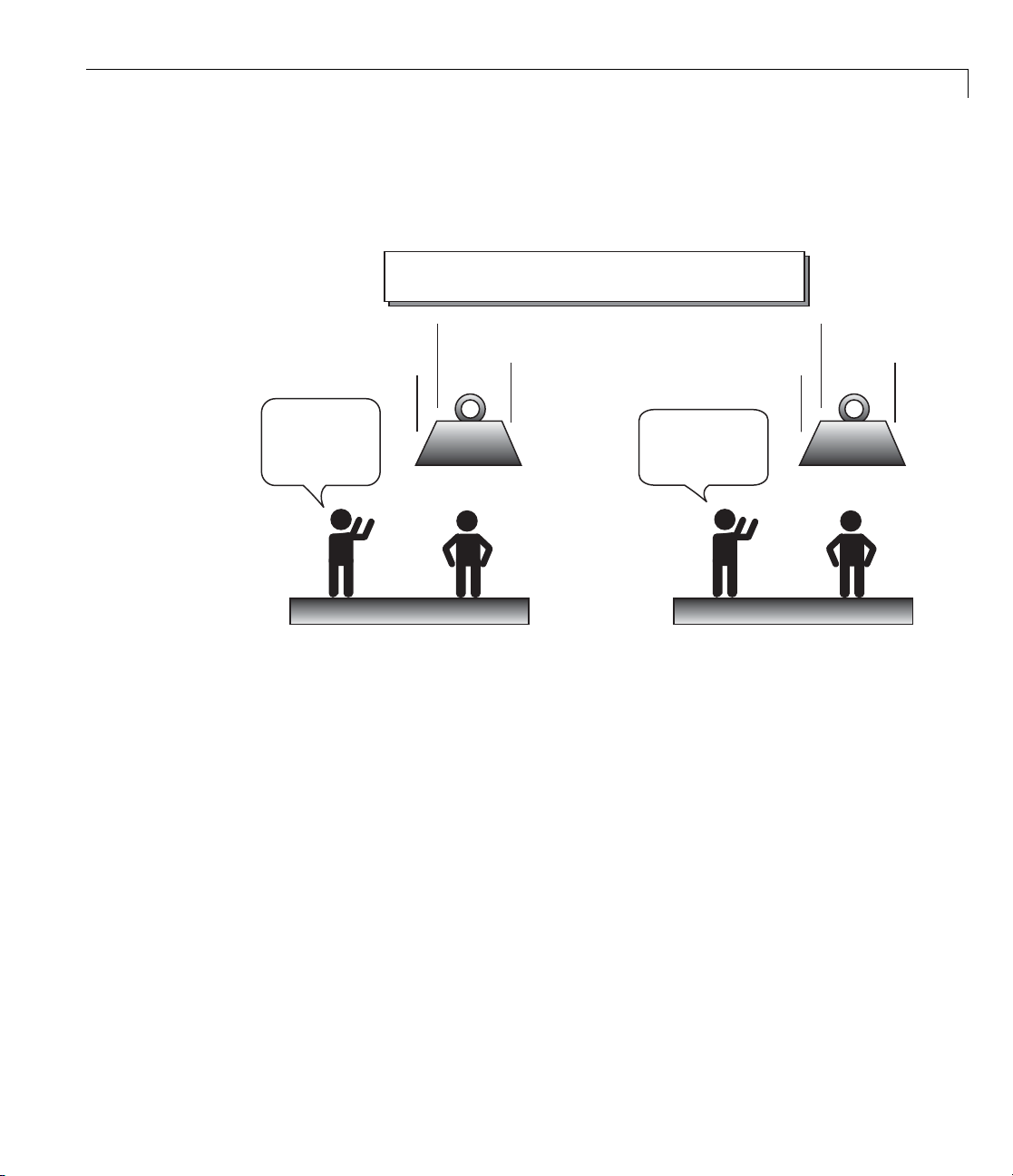
Precision and Significance in the Real World
A 1500 kg mass
is approaching
your head at
45.3 m/s
LOOK
OUT!!
Precision Significance
Fuzzy l
Mappin
follow
• With i
• With y
• With
• Wit
Ag
ogic is a convenient way to map an input space to an output space.
g input to output is the starting point for eve rything. Consider the
ing examples:
nformation about how good your service was at a restaurant, a fuzzy
system can tell you what the tip should be.
logic
our specification of how hot you want the water, a fuzzy logic system
djust the faucet valve to the right setting.
can a
information about ho w far away the subject of your photograph is,
zy logic system can focus the lens for you.
afuz
h information about how fast the car is going and how hard the motor is
king,afuzzylogicsystemcanshiftgearsforyou.
wor
raphical example of an input-output map is shown in the following figure.
1-7
Page 18

1 Getting Started
Input Space
(all possible service
quality ratings)
Output Space
(all possible tips)
Black
tonight's service
quality
Box
An input-output map for the tipping problem:
Given the quality of service, how much should I tip?
To determine the appropriate amount of tip requires mapping inputs to the
appropriate outputs. Between the input and the output, the preceding figure
shows a black box that can contain any number of things: fuzzy systems,
linear systems, expert systems, neural networks, differential equations,
interpolated m ultidimensio nal lookup tables, or even a spiritual advisor, just
to name a few of the possible optio ns. Clearly the list could go on and on.
Of the dozens of ways to make the black box work, it turns out that fuzzy
is often the very best way. Why should that be? As Lotfi Zadeh, who is
considered to be the father of fuzzy logic, once remarked: “In almost every
case you can build the same product without fuzzy logic, but fuzzy is faster
and cheaper.”
the "right" tip
for tonight
1-8
Why Use Fuzzy Logic?
Here is a list of general observations about fuzzy logic:
• Fuzzy logic is conceptually easy to understand.
The mathematical concepts behind fuzzy reasoning are very simple. Fuzzy
logic is a more intuitive approach without the far-reaching complexity.
• Fuzzy logic is flexible.
With any given system, it is easy to layer on more functionality without
starting again from scratch.
• Fuzzy logic is tolerant of imprecise data.
Page 19

What Is Fuzzy Logic?
Everything is imprecise if you look closely enough, but more than that, most
things are imprecise even on careful inspection. Fuzzy reasoning builds
this understanding into the process rather than tacking it onto the end.
• Fuzzy logic can model nonlinear functions of arbitrary complexity.
You can create a fuzzy system to match any set of input-output data. This
process is made particularly easy by adaptive techniques like Adaptive
Neuro-Fuzzy Inference Systems (ANFIS), which are available in Fuzzy
Logic Toolbox software.
• Fuzzy logic can be built on top of the expe rience of experts.
In direct contrast to neural networks, which take training data and
generate opaque, impenetrable models, fuzzy logic lets you rely on the
experience of people who already understand your system.
• Fuzzy logic can be blended with conventional control techniques.
Fuzzy systems don’t necessarily replace conventional control methods.
In many cases fuzzy systems augment them and simplify their
implementation.
• Fuzzy logic is based on natural language.
The basis for fuzzy logic is the basis for human communication. This
observation underpins many of the other statements about fuzzy logic.
Because fuzzy logic is built on the structures of qualitative description used
in everyday language, fuzzy logic is easy to use.
The last statement is perhaps the most important one and deserves more
discussion. Natural language, which is used by ordinary people on a daily
basis, has been shaped by thousands of years of human history to be
convenient and efficient. Sentences written in ordinary language represent a
triumph of efficient communication.
When Not to Use Fuzzy Logic
Fuzzy logic is not a cure-all. When should you not use fuzzy logic? The safest
statement is the first one made in this introduction: fuzzy logic is a convenient
way to map an input space to an output space. If you find it’s not convenient,
try something else. If a simpler solution already exists, use it. Fuzzy logic is
the codification of common sense — use common sense when you implement it
and you will probably make the right decision. Many controllers, for example,
1-9
Page 20

1 Getting Started
do a fine job without using fuzzy logic. However, if you take the time to
become familiar with fuzzy logic, you’ll see it can be a very powerful tool for
dealing quickly and efficiently with imprecision and nonlinearity.
What Can Fuzzy Logic Toolbox Software Do?
You can create and edit fuzzy inference systems with Fuzzy Logic Toolbox
software. You can create these systems using graphical tools or command-line
functions, or you can generate them automatically using either clustering
or adaptive neuro-fuzzy techniques.
If you have access to Simulink software, you can easily test your fuzzy system
in a block diagram simulation environment.
The toolbox also lets you run your own stand-alone C programs directly.
This is m ade possible by a stand-alone Fuzzy Inference Engine that reads
the fuzzy systems saved from a MATLAB session. You can customize the
stand-alone engine to build fuzzy inference into your own code. All provided
code is ANSI compliant.
1-10
Fuzzy
Inference
System
Fuzzy
Logic
Toolbox
Simulink
Stand-alone
Fuzzy Engine
User-written
M-files
Other toolboxes
MATLAB
Because of the integrated nature of the MATLAB environment, you can
create your own tools to customize the toolbox or harness it with another
Page 21

What Is Fuzzy Logic?
toolbox, such as the Control System Toolbox™, N eural Network Toolbox™,
or Optimization Toolbox™ software.
1-11
Page 22

1 Getting Started
An Introductory Example: Fuzzy Versus Nonfuzzy Logic
In this section...
“The Basic Tipping Problem” on page 1-12
“The Nonfuzzy Approach” on page 1-12
“The Fuzzy Logic Approach” on page 1-16
“Problem Solution” on page 1-17
The Basic Tipping Problem
To illustrate the value of fuzzy logic, examine both linear and fuzzy
approaches to the following problem:
What is the right amount to tip your waitperson?
First, work through this problem the conventional (nonfuzzy) way, writing
MATLAB commands that spell out linear and piecewise-linear relations.
Then, look at the same system using fuzzy logic.
1-12
The Basic Tipping Problem. Given a number between 0 and 10 that
represents the quality of service at a restaurant (where 10 is excellent), what
should the tip be?
Note This problem is based on tipping as it is typically practiced in the
United States. An average tip for a meal in the U.S. is 15%, though the actual
amount may vary d epending on the quality of the service provided.
The Nonfuzzy Approach
Begin with the simplest possible relationship. Suppose that the tip always
equals 15% of the total bill.
tip = 0.15
Page 23

An Introductory Example: Fuzzy Versus Nonfuzzy Logic
0
service
tip
0 2 4 6 8 10
0.05
0.1
0.15
0.2
0.25
service
tip
0.25
0.2
0.15
0.1
0.05
0
0 2 4 6 8 1
This relationship does not take into account the quality of the service, so you
need to add a new term to the equation. Because service is rated on a scale of
0 to 10, you m ight have the tip go linearly from 5% if the service is bad to 25%
if th e service is excellent. Now the relation looks like the following plot:
tip=0.20/10*service+0.05
The formula does what you want it to do, and is straightforward. How ev er,
you may want the tip to reflect the quality of the food as well. This extension
of the problem is defined as follows.
The Extended Tipping Problem. Given two sets of numbers between 0 and
10 (where 10 is excellent) that respectively represent the quality of the service
and the quality of the food at a restaurant, what should the tip be?
1-13
Page 24

1 Getting Started
0
service
tip
0
5
10
0
5
10
0.05
0.1
0.15
0.2
0.25
service
food
tip
See how the formula is affected now that you have added another v ariable.
Try the following equation:
tip = 0.20/20*(service+food)+0.05;
0.25
0.2
0.15
0.1
0.05
10
food
5
0
0
5
1
In this case, the results look satisfactory, but when you look at them closely,
they do not seem quite right. Suppose you w ant the service to be a more
important factor than the food quality. Specify that service accounts for 80%
of the overall tipping grade and the food makes up the other 20%. Try this
equation:
1-14
servRatio=0.8;
tip=servRatio*(0.20/10*service+0.05) + ...
(1-servRatio)*(0.20/10*food+0.05);
The response is still somehow too uniformly linear. Suppose you want more of
a flat response in the middle, i.e., you want to give a 15% tip in general, but
Page 25

An Introductory Example: Fuzzy Versus Nonfuzzy Logic
0 2 4 6 8 10
0.05
0.1
0.15
0.2
0.25
service
tip
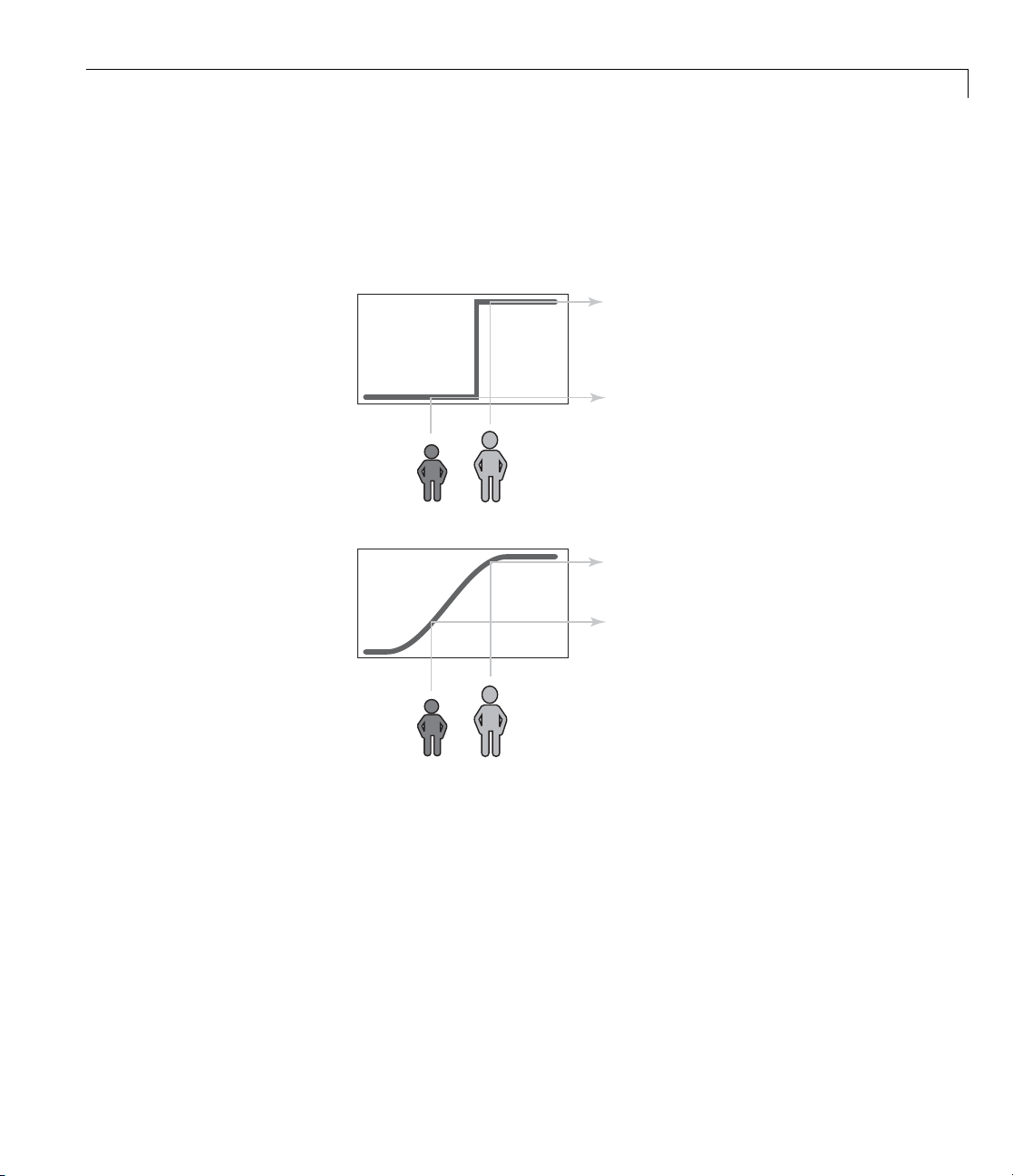
want to also specify a variation if the service is exceptionally good or bad. This
factor, in turn, means that the previous linear mappings no longer apply. You
can still use the linear calculation with a piecewise linear construction. Now,
return to the one-dimensional problem of just considering the service. You can
string together a simple conditional statement using breakpoints like this.
if service<3,
tip=(0.10/3)*service+0.05;
elseif service<7,
tip=0.15;
elseif service<=10,
tip=(0.10/3)*(service-7)+0.15;
end
The plot now looks like the following figure:
If you extend this to two dimensions, where you take food into account again,
something like the following output results.
servRatio=0.8;
if service<3,
elseif service<7,
tip=((0.10/3)*service+0.05)*servRatio + ...
(1-servRatio)*(0.20/10*food+0.05);
1-15
Page 26

1 Getting Started
0
service
tip
tip=(0.15)*servRatio + ...
(1-servRatio)*(0.20/10*food+0.05);
else,
tip=((0.10/3)*(service-7)+0.15)*servRatio + ...
(1-servRatio)*(0.20/10*food+0.05);
end
0.25
0.2
0.15
0.1
0.05
10
1
5
food
0
0
5
1-16
The plot looks good, but the function is surprisingly complicated. It was a
little d if fi cult to code this correctly, and it is definitely not easy to m odify this
code in the future. Moreover, it is even less apparent how the algorithm works
to someone who did not see the original design process.
The Fuzzy Logic Approach
You need to capture the essentials of this problem, leaving aside all the
factors that could be arbitrary. If you make a list of what really matters in
this problem, you mig ht end up with the following rule descriptions.
Tipping Problem Rules — Service Factor
If service is poor, then tip is cheap
If service is good, then tip is average
If service is excellent, then tip is generous
Page 27

An Introductory Example: Fuzzy Versus Nonfuzzy Logic
The order in which the rules are presented here is arbitrary. It does not
matter which rules come first. If you want to include the food’s effect on the
tip, add the following two rules.
Tipping Problem Rules — Food Factor
If food is rancid, then tip is cheap
If food is delicious, then tip is generous
You can combine the two different lists o f rules into one tight list of three
rules like so.
Tipping Problem — Both Service and Food Factors
If se rvice is poor or the food is rancid, then tip is cheap
If service is good, then tip is average
If service is excellent or food is delicious, then tip is generous
These three rules are the core of your solution. Coincidentally, you have just
defined the rules for a fuzzy logic system. When you give mathematical
meaning to the linguistic variables (what is an average tip, for example?)
you have a complete fuzzy inference sy stem. The methodology of fuzzy logic
must also consider:
• How are the rules all combined?
• How do I define mathematically what an average tip is?
The next few chapters provide detailed answers to these questions. The
details of the method don’t really change much from problem to problem—the
mechanics of fuzzy logic aren’t terribly complex. What matters is that you
understand that fuzzy logic is adaptable, simple, and easily applied.
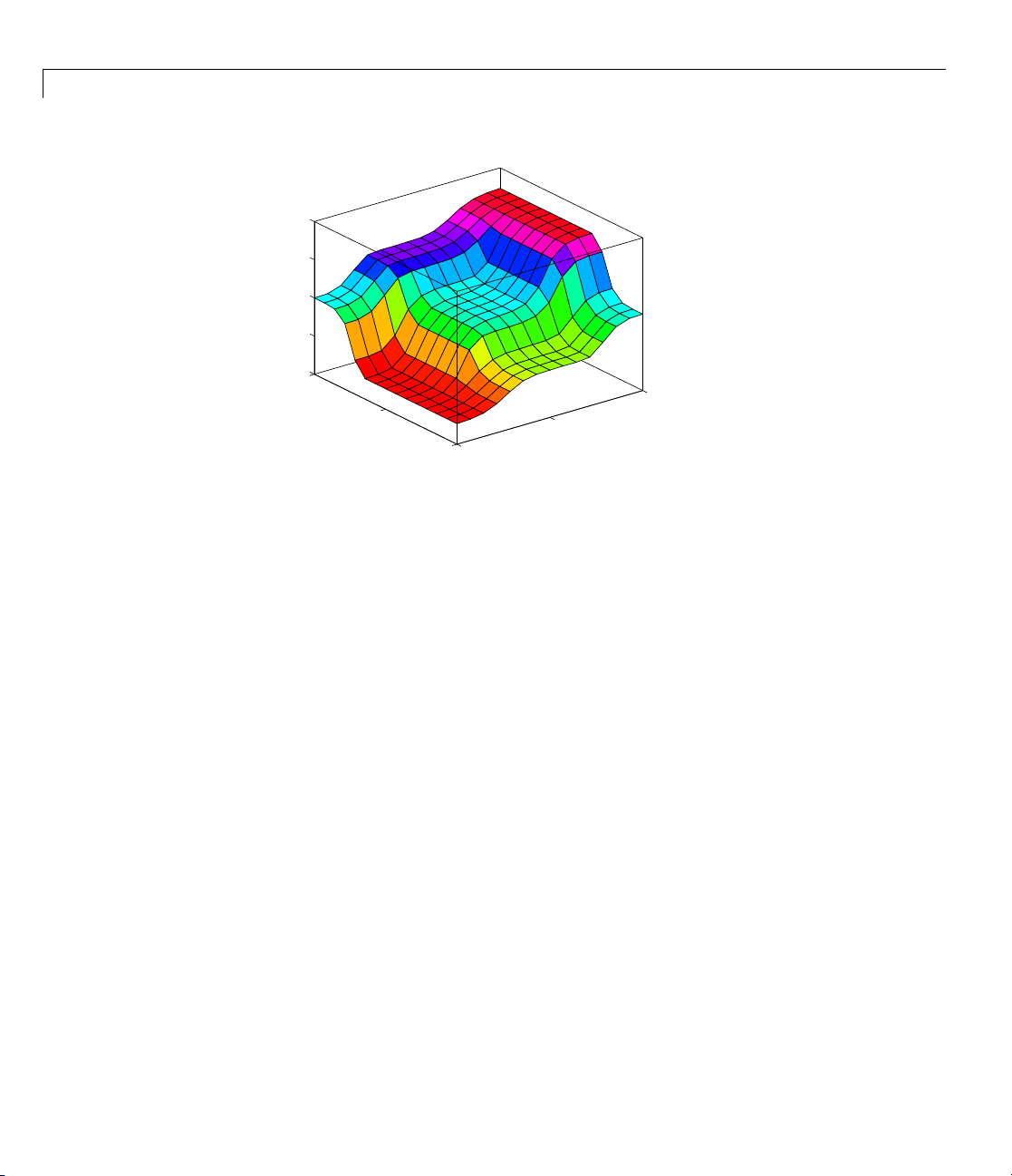
Problem Solution
The following plot represents the fuzzy logic system that solves the tipping
problem.
1-17
Page 28
1 Getting Started
0
service
tip
0.25
0.2
0.15
0.1
0.05
10
food
5
0
0
5
1
This plot was generated by the three rules that accounted for both service
and food factors. The mechanics of how fuzzy inference works is explained
in “Overview” on page 2-2, “Foundations of Fuzzy Logic” on page 2-4, and in
“Fuzzy Inference Systems” on page 2-20. In “Building Systems with Fuzzy
LogicToolboxSoftware”onpage2-31,theentiretippingproblemisworked
through using the Fuzzy Logic Toolbox graphical tools.
1-18
Observations
Consider so me observations about the examplesofar. Youfoundapiecewise
linear relation that solved the problem. It worked, but it was problematic to
derive, and when you wrote it down as code, it was not very easy to interpret.
Conversely, the fuzzy logic sys tem is based on some common sense statements.
Also, you were able to add two more rules to the bottom of the list that
influenced the shape of the overall output without needing to undo what had
already been done, making the subsequent modification was relatively easy.
Moreover, by using fuzzy logic rules, the maintenance of the structure of
the algorithm decouples along fairly cle an lines. The notion of an average
tip might change from day to day, city to city, country to country, but the
underlying logic is the same: if the service is good, the tip should be average.
Page 29

An Introductory Example: Fuzzy Versus Nonfuzzy Logic
Recalibrating the Method
You can recalibrate the method quickly by simply shifting the fuzzy set that
defines average without rewriting the fuzzy logic rules.
You can shift lists of piecewise linear functions, but there is a greater
likelihood that recalibration will not be so quick and simple.
In the following example, the piecew i se linear tipping problem slightly
rewritten to make it more generic. It performs the same function as before,
only now the constants can be easily changed.
% Establish constants
lowTip=0.05; averTip=0.15; highTip=0.25;
tipRange=highTip-lowTip;
badService=0; okayService=3;
goodService=7; greatService=10;
serviceRange=greatService-badService;
badFood=0; greatFood=10;
foodRange=greatFood-badFood;
% If service is poor or food is rancid, tip is cheap
if service<okayService,
tip=(((averTip-lowTip)/(okayService-badService)) ...
*service+lowTip)*servRatio + ...
(1-servRatio)*(tipRange/foodRange*food+lowTip);
% If service is good, tip is average
elseif service<goodService,
tip=averTip*servRatio + (1-servRatio)* ...
(tipRange/foodRange*food+lowTip);
% If service is excellent or food is delicious, tip is generous
else,
tip=(((highTip-averTip)/ ...
(greatService-goodService))* ...
(service-goodService)+averTip)*servRatio + ...
(1-servRatio)*(tipRange/foodRange*food+lowTip);
end
As with all code, the more generality that is introduced, the less precise the
algorithm becomes. While you can improve clarity by adding more comments,
1-19
Page 30

1 Getting Started
or perhaps rewriting the algorithm in slightly more self-evident ways, but the
piecewise linear methodology is not the optimal way to resolve this issue.
If you remove everything from the algorithm except for three comments, what
remain are exactly the fuzzy logic rules you previously wrote down.
% If service is poor or food is rancid, tip is cheap
% If service is good, tip is average
% If service is excellent or food is delicious, tip is generous
If, as with a fuzzy system, the comment is identical with the code, think
how much more likely your code is to have comments. Fuzzy logic lets the
language that is clearest to you, high level comments, also have meaning to
the machine, which is why it is a very successful technique for bridging the
gap between people and machines.
By making the eq u ation s as simple as possible (linear) you make things
simpler for the machine but more complicated for you. However, the
limitation is really no longer the computer—it is your mental model of what
the computer is doing. Computers have the ability to make things hopelessly
complex; fuzzy logic reclaims the middle ground and lets the machine work
with your preferences rather than the other way around.
1-20
Page 31

Tutorial
• “Overview” on page 2-2
• “Foundations of Fuzzy Logic” on page 2-4
• “Fuzzy Inference Systems” on page 2-20
• “Building Systems with Fuzzy Logic Toolbox Software” on page 2-31
• “Building Fuzzy Inf eren ce Systems Using Custom Functions” on page 2-59
• “Working from the Command Line” on page 2-73
• “Working in Simulink Environment” on page 2-87
2
• “Sugeno-Type Fuzzy Inference” on page 2-100
• “anfis and the ANFIS Editor GUI” on page 2-108
• “Fuzzy Clustering” on page 2-150
• “Simulating Fuzzy Inference Systems Using the Fuzzy Inference Engine”
on page 2-172
Page 32

2 Tutorial
Overview
The point of fuzzy logic is to map an input space to an output space, and the
primary mechanism for doing this is a list of if-then statements called rules.
All rules are evaluated in parallel, and the order of the rules is unimportant.
The rules themselves are useful because they refer to variables and the
adjectives that describe those variables. Before you can build a system that
interpretsrules,youmustdefineallthetermsyouplanonusingandthe
adjectives that describe them. To say that the water is hot, you need to define
the range that the water’s temperature can be expected to vary as well as
what we mean by the word hot. The following diagram provides a roadmap for
the fuzzy inference process. It shows the g eneral description of a fuzzy system
on the left and a specific fuzzy system (the tipping example from Chapter 1,
“Getting Started”) on the right.
The General Case A Specific Example
Input
Rules
Input
terms
(interpret)
To sum
infer
on so
This
step
fir
gen
imp
Th
marize the concept of fuzzy infe renc e depicted in this figure, fuzzy
ence is a method that interprets the values in the input vector and, based
me set of rules, assigns values to the output vector.
section i s designed to guide you through the fuzzy logic process step by
by providing an introduction to the theory and practice of fuzzy logic. The
st three sections of this section are the most important—they move from
eral to specif ic, first introducing underlying ideas and then discussing
lementation details specific to the toolbox.
ese three areas are as follows:
Output service
if service is poor then tip is cheap
if service is good then tip is average
if service is excellent then tip is generous
Output
terms
(assign)
service
is interpreted as
{poor,
good,
excellent}
tip
tip
is assigned to be
{cheap,
average,
generous}
2-2
Page 33

• “Foundations of Fuzzy Logic” on page 2-4, which is an introduction to the
general concepts. If you are already familiar with f uzzy logic, you can skip
this section.
• “Fuzzy Inference Systems” on page 2-20, which explains the specific
methods of fuzzy inference used in the toolbox. Because the field of fuzzy
logic uses many terms that do not y et have standard interpretations, read
this section to become familiar with the fuzzy inference process as it is
employed through the toolbox.
• “Building Systems with Fuzzy Logic Toolbox Software” on page 2-31,
which goes into detail about how you build and edit a fuzzy system using
this toolbox. This topic provides a quick start orientation to the Fuzzy
Logic Toolbox graph ical user interface tools and guides you through the
construction of a comple t e fuzzy infe rence system from start to finish.
After these three topics, there are additional topics, such as using the toolbox
in Simulink environment, automatic rule generation, and demonstrations.
Overview
2-3
Page 34

2 Tutorial
Foundations of Fuzzy Logic
In this section...
“Fuzzy Sets” on page 2-4
“Membership Functions” on page 2-8
“Logical Operations” on page 2-13
“If-Then Rules” on page 2-16
Fuzzy Sets
Fuzzy logic starts with the concept of a fuzzy set. A fuzzy set is a set without a
crisp, clearly defined boundary. It can contain elements with only a partial
degree of membership.
To understand what a fuzzy set is, first consider the definition of a classical
set. A classical set is a container that wholly includes or wholly excludes
any give n element. For e xample , the set of days of the week unquestionably
includes Monday, Thursday, and Saturday. It just as unquestionably excludes
butter, liberty, and dorsal fins, and so on.
2-4
Shoe
Polish
Butter
This type of set is called a classical set because it has been around for a long
time. It was Aristotle who first formulated the Law of the Excluded Middle,
which says X must either be in set A or in set not-A. Another version of this
law is:
Of any subject, one thing must be either asserted or denied.
To restate this law with annotations: “O f any s ub je c t (say M on d ay ), one th ing
(a day of the week) must be either asserted or denied (I assert that Monday
Monday
Thursday
Saturday
Days of the week
Liberty
Dorsal
Fins
Page 35

Foundations of Fuzzy Logic
is a day of the week).” This law demands that opposites, the two categories
A and not-A, should between them contain the entire universe. Everything
falls into either one group or the other. There is no thing that is both a day of
the week and not a day of the week.
Now, consider the set of days comprising a weekend. The following diagram
attempts to classify the weekend days.
Shoe
Liberty
Polish
Monday
Saturday
Friday
Sunday
Thursday
Dorsal
Butter
Days of the weekend
Most would
It feels l
technica
“straddl
classif
somethi
Of cour
accoun
imprec
to Mond
stops being helpful. Fuzzy reasoning becomes valuable exactly when you
logic
work w
e-minded classification useful for accounting purposes only. More than
simpl
hing else, the following statement lays the foundations for fuzzy logic.
anyt
agree that Saturday and Sunday belong, but what about Friday?
ike a part of the weekend, but somehow it seems like it should be
lly excluded. Thus, in the preceding diagram, Friday tries its best to
e on the fence.” Classical or normal sets would not tolerate this kind of
ication. Either something is in or it is out. H u m an experience suggests
ng different, however, straddling the fence is part of life.
se individual perceptions and cultural background must be taken into
t when you define what constitutes the weekend. Even the dictionary is
ise, defining the weekend as the period from Friday night or Saturday
ay morning. You are entering the realm where sharp-edged, yes-no
ith how people really perceive the concept weekend as opposed to a
Fins
In fuzzy logic, the truth of any statement becomes a matter of degree.
Any statement can be fuzzy. The major advantage that fuzzy reasoning
offers is the ability to reply to a yes-no question with a not-quite-yes-or-no
answer. Humans do this kind of thing all the time (think how rarely you get
a straight answer to a seemingly simple question), but it is a rather new
trick for computers.
2-5
Page 36

2 Tutorial
How does it work? Reasoning in fuzzy logicisjustamatterofgeneralizing
the f amiliar yes-no (Boolean) logic. If you give true the numerical value of 1
and false the numerical value of 0, this value indicates that fuzzy logic also
permits in-between values like 0.2 and 0.7453. For instance:
Q: Is Saturday a weekend day?
A: 1 (yes, or true)
Q: Is Tuesday a weekend day?
A: 0 (no, or false)
Q: Is Friday a weekend day?
A: 0.8 (for the most part yes, but not completely)
Q: Is Sunday a weekend day?
A: 0.95 (yes, but not quite as much as Saturday).
The following plot on the left shows the truth values for weekend-ness if you
areforcedtorespondwithanabsoluteyesornoresponse. Ontheright,isa
plot that shows the truth value for weekend-ness if you are allowed to respond
with fuzzy in-between values.
2-6
1.0
weekend-ness
0.0
FridayThursday
Days of the weekend two-valued membership
Saturday Sunday Monday
1.0
weekend-ness
0.0
Friday Saturday Sunday MondayThursday
Days of the weekend multivalued membership
Technically, the representation on the right is from the domain of multivalued
logic (or multivalent logic). If you ask the question “Is X a member of set
A?” the answer might be yes, no, or any one of a thousand intermediate
values in between. Th us, X might h ave parti al membership in A. Multivalued
logic stands in direct contrast to the more familiar concept of two-valued (or
bivalent yes-no) logic.
To return to the example, now consider a continuous scale time plot of
weekend-ness shown in the following plots.
Page 37

Foundations of Fuzzy Logic
1.0
weekend-ness
0.0
Friday Saturday Sunday MondayThursday
Days of the weekend two-valued membership
1.0
weekend-ness
0.0
Friday Saturday Sunday MondayThursday
Days of the weekend multivalued membership
By making the plot continuous, you are defining the degree to which any given
instant belongs in the weekend rather than an entire day. In the plot on the
left, notice that at midnight on Friday, just as the second hand sweeps past
12, the weekend-ness truth value jumps discontinuously from 0 to 1. This is
one way to define the w eekend, and while it may be useful to an accountant, it
may not really connect with your own real-world experience of weekend-ness.
Theplotontherightshowsasmoothlyvarying curve that accounts for the fact
that all of Friday, and, to a small degree, parts of Thursday, partake of the
quality of weekend-ness and thus deserve partial mem bership in the fuzzy set
of weekend moments. The curve that defines the w eekend-ne ss of any instant
in time is a function that maps the input space (time of the week) to the output
space (weekend-ness). Specifically it is known as a membership function.See
“Membership Functions” on page 3-3 for a more detailed discussion.
As another example of fuzzy sets, consider the question of seasons. What
season is it right now? In the northern hemisphere, summer officially begins
at the exact moment in the earth’s orbit when the North Pole is pointed most
directly toward the sun. It occurs exactly once a year, in late June. Using the
astronomical definitions for the season, you get sharp boundaries as shown
on the left in the figure that follows. But what you experience as the seasons
vary more or less continuously as shown on the right in the following figure
(in temperate northern hemisphere climates).
2-7
Page 38

2 Tutorial
springsummer fall winter
1.0
degree
of
member-
ship
0.0
March March
June September December
Time of the
year
degree
member-
ship
springsummer fall winter
1.0
of
0.0
March March
June September December
Time of the
year
Membership Functions
A membership function (MF) is a curve that defines how each point in the
input space is mapped to a membership value (or degree of membership)
between 0 and 1. The input space is sometimes referred to as the universe of
discourse,afancynameforasimpleconcept.
One of the most commonly used examples of a fuzzy set is the set of tall
people. In this case, the universe of discourse is all potential heights, say from
3 feet to 9 feet, and the word tall would correspond to a curve that defines
thedegreetowhichanypersonistall. Ifthesetoftallpeopleisgiventhe
well-defined (crisp) boundary of a classical set, you might say all people taller
than 6 feet ar e officially considered tall. However, such a distinction is clearly
absurd. It may make sense to consider the set of all real numbers greater
than 6 because numbers belong on an abstract plane, but when we want to
talk abou t real people, it is unreasonable to call one person short and another
one tall when they differ in height by the width of a hair.
2-8
excellent!
You must be
taller than
this line to
be
considered
TALL
If the kind of distinction shown previously is unworkable, then what is the
right way to define the set of tall peop le ? Much as with the plot of weekend
days, the figure following shows a smoothly varying curve that passes from
Page 39
Foundations of Fuzzy Logic
not-tall to tall. The output-axis is a number known as the membership value
between 0 and 1. The curve is known as a membership function and is often
given the designation of µ. This curve defines the transition from not tall to
tall. Both people are tall to some degree, but one is significantly less tall
than the other.
tall (m = 1.0)
not tall (m = 0.0)
definitely a tall
person (m = 0.95)
really not very
tall at all (m = 0.30)
degree of
membership, µ
degree of
membership, µ
1.0
0.0
1.0
0.0
sharp-edged
membership
function for
continuous
membership
function for
TALL
TALL
height
height
Subjective interpretations and appropriateunitsarebuiltrightintofuzzy
sets. If you say “She’s tall,” the membership function tall should already take
into account whether you are referring to a six-year-old or a grown woman.
Similarly, the units are included in the curve. Certainly it makes no sense to
say “Is she tall in inches or in meters?”
Membership Functions in Fuzzy Logic Toolbox Software
The only condition a membership function must really satisfy is that it must
vary between 0 and 1. The function itself can be a n arbitrary curve whose
shape we can define as a function that suits us from the point of view of
simplicity, convenience, speed, and efficiency.
2-9
Page 40

2 Tutorial
A classical set might be expressed as
A={x | x >6}
A fuzzy set is an extension of a classical set. If X is the universe of discourse
and its elements are denoted by x,thenafuzzysetAinXisdefinedasa
set of ordered pairs.
A={x,µ
µ
(x) is called the m embers hip function (or MF) of x in A. The membership
A
(x) | x X}
A
function maps each element of X to a membership value between 0 and 1.
The toolbox includes 11 built-in membership function types. These 11
functions are, in turn, built from several basic functions:
• piece-wise linear functions
• the Gaussian distribution function
• the sigmoid curve
• quadratic and cubic polynomial curves
For detailed i nformatio n on any of the membership functions mentioned
next, turn to Chapter 4, “Functions — Alphabetical List”. By convention, all
membership functions have the letters
mf at the end of their names.
The simplest membership functions are formed using straight lines. Of these,
the simplest is the triangular membership function, and it has the function
name
trimf. This function is nothing more than a collection of three points
forming a triangle. The trapezoidal membership function,
trapmf,hasa
flat top and really is just a truncated triangle curve. These straight line
membership functions have the advantage of simplicity.
2-10
Page 41

Foundations of Fuzzy Logic
0
0
0
trimf, P = [3 6 8]
0
0
0
trapmf, P = [1 5 7 8]
0
0
0
gaussmf, P = [2 5]
0
0
0
gauss2mf, P = [1 3 3 4]
0
0
0
gbellmf, P = [2 4 6]
1
.75
0.5
.25
0
0 2 4 6 8 1
trimf
1
.75
0.5
.25
0
0 2 4 6 8 1
trapmf
Two membership functions are built on the Gaussian distribution curve: a
simple Gaussian curve and a two-sided composite of two different Gaussian
curves. The two functions are
gaussmf and gauss2mf.
The generalized bell membership function is specified by three parameters
and has the function name
gbellmf. The bell membership function has one
more parameter than the Gaussian membership function, so it can approach
a non-fuzzy set if the free parameter is tuned. Because of their smoothness
and concise notation, Gaussian and bell membership functions are popular
methods for specifying fuzzy sets. Both of these curves have the advantage of
being smooth and nonzero at all points.
1
.75
0.5
.25
0
0 2 4 6 8 1
1
.75
0.5
.25
0
0 2 4 6 8 1
1
.75
0.5
.25
0
0 2 4 6 8 1
gaussmf
gauss2mf
gbellmf
Although the Gaussian membership functions and bell membership functions
achieve smoothness, they are unable to specify asymmetric membership
functions, which are important in certain applications. Next, you define the
sigmoidal membership function, which is either open left or right. Asymmetric
and closed (i.e. not open to the left or right) membership functions can be
synthesized using two sigmoidal functions, so in addition to the basic
you also have the difference between two sigmoidal functions,
product of two sigmoidal functions
psigmf.
dsigmf,andthe
sigmf,
2-11
Page 42

2 Tutorial
0
0
0
dsigmf, P = [5 2 5 7]
0
0
0
psigmf, P = [2 3 −5 8]
0
0
0
sigmf, P = [2 4]
0
0
0
pimf, P = [1 4 5 10]
0
0
0
smf, P = [1 8]
0
0
0
zmf, P = [3 7]
1
.75
0.5
.25
0
0 2 4 6 8 1
sigmf
1
.75
0.5
.25
0
0 2 4 6 8 1
dsigmf
1
.75
0.5
.25
0
0 2 4 6 8 1
psigmf
Polynomial based curves account for several of the membership functions in
the toolbox . Three related membership functions are the Z, S,andPi curves,
all named because of their shape. The function
polynomial curve open to the left,
to the right, and
1
.75
0.5
.25
0
0 2 4 6 8 1
pimf is zero on both extre m es with a rise in the middle.
zmf
smf is the mirror-image function that opens
1
.75
0.5
.25
0
0 2 4 6 8 1
pimf
zmf is the asymmetrical
1
.75
0.5
.25
0
0 2 4 6 8 1
smf
Thereisaverywideselectiontochoosefromwhenyou’reselectinga
membership function. You can also create your own membership functions
with the toolbox. However, if a list based on expanded membership functions
seems too complicated, jus t remember that you could probably get along very
well with just one or two types of membership functions, for example the
triangle and trapezoid functions. The selection is wide for those who want
to explore the possibilities, but expansive membership functions are not
necessary for good fuzzy inference systems. Finally, remember that more
details are available on all these functions in the reference section.
Summary of Membership Functions
• Fuzzy sets describe vague concepts (e.g., fast runner, hot weather, weekend
days).
2-12
Page 43

Foundations of Fuzzy Logic
• A fuzzy set admits the possibility of partial membership in it. (e.g., Friday
is sort of a weekend day, the weather is rather hot).
• The degree an object belongs to a fuzzy set is denoted by a members hip
value between 0 and 1. (e.g., Friday is a weekend day to the degree 0.8).
• A membership function associated with a given fuzzy set maps an input
valuetoitsappropriatemembershipvalue.
Logical Operations
Now that you understand the fuzzy inference, you need to se e how fuzzy
inference connects with logical operations.
The most important thing to realize about fuzzy logical reasoning is the fact
that it is a superset of standard Boolean logic. In other words, if you keep the
fuzzy values at their extremes of 1 (completely true), and 0 (completely false),
standard logical operations will hold. As an example, consider the following
standard truth tables.
A B A and B A B A or B A not A
0
0
1
1
0
1
0
1
AND
0
0
0
1
0
0
1
1
0
1
0
1
0
1
1
1
OR
0
1
NOT
1
0
Now, because in fuzzy logic the truth of any statem ent is a matter of degree,
can these truth tables be a ltered? The input values can be real numbers
between 0 and 1. What function preserves the results of the AND truth table
(for example) and also extend to all real numbers between 0 and 1?
One answer is the min operation. That is, resolve the statement A AND B,
where A and B are limited to the range (0,1), by using the function min(A,B).
Using the same reasoning, you can replace the OR operation with the max
function, so that A OR B becomes equivalent to max(A,B). Finally, the
operation NOT A become s equivalent to the operation
.Noticehowthe
1− A
previous truth table is com pletely unchanged by this substitution.
2-13
Page 44

2 Tutorial
A B min(A,B) A B max(A,B) A 1 - A
0
0
1
1
0
1
0
1
0
0
0
1
0
0
1
1
0
1
0
1
0
1
1
1
0
1
1
0
AND
OR
NOT
Moreover, because there is a function behind the truth table rather than just
the truth table itself, you can now consider values other than 1 and 0.
The next figure uses a graph to show the same information. In this figure, the
truth table is converted to a plot of two fuzzy sets applied together to create
onefuzzyset.Theupperpartofthefiguredisplaysplotscorrespondingtothe
preceding two-value d truth tables , while the lower part of the figure displays
how the operations work over a continuously varying range of truth values A
and B according to the fuzzy operations you have defined.
A
B
A or B
B
A or B
Two-valued
logic
Multivalued
logic
A
B
A and
B
A
B
A and
B
A
A
not A
A
not A
2-14
AND
min(A,B) max(A,B) (1-A)
OR NOT
Page 45

Foundations of Fuzzy Logic
Given these three functions, you can resolve any construction using fuzzy sets
and the fuzzy logical operation AND, OR, and NOT.
Additional Fuzzy Operators
In this case, you defined only one particular correspondence between
two-valued and multivalued logical operations for AND, OR, and NOT. This
correspondence is by no means unique.
In more general terms, you are defining what are known as the fuzzy
intersection or conjunction (AND), fuzzy union or disjunction (OR), and fuzzy
complement (NOT). The classical operators for these functions are: AND =
min,OR=max, and NOT = additive complement. Typically, most fuzzy logic
applications make use of these operations and leave it at that. In general,
however, these functions are a rbitrary to a surprising degree. Fuzzy Logic
Toolbox software uses the classical operator for the fuzzy complement as
shown in the previous figure, but also enables you to customize the AND
and OR operators.
The intersection of two fuzzy sets A and B is specified in general by a binary
mapping T, which aggregates two membership functions as follows:
µ
(x)=T(µA(x), µB(x))
A∩B
For example, the binary operator T may represent the multiplication of
μμ
xx
and
() ()
A
. These fuzzy intersection operators, which are usually
B
referred to as T-norm (Triangular norm) operators, meet the following basic
requirements:
A T-norm operator is a binary mapping T(
.,.) satisfying
boundary: T(0, 0) = 0, T(a,1)=T(1, a) = a
monotonicity: T(a, b) <= T(c, d) if a<=cand b<=d
commutativity: T(a, b) = T(b, a)
associativity: T(a, T(b, c)) = T (T(a, b), c)
The first requirement imposes the correct generalization to crisp sets. The
second requirement implies that a decrease in the membership values in A or
B cannot produce an increase in the membership value in A intersection B.
The third requirement indicates that theoperatorisindifferent to the order of
2-15
Page 46

2 Tutorial
the fuzzy sets to be combined. Finally, the fourth requirement allows us to
take the intersection of any number of sets in any order of pair-wise groupings.
Like fuzzy intersection, the fuzzy union operator is specified in general by
a binary mapping S:
µ
(x)=S(µA(x), µB(x))
A∩B
For example, the binary operator S can represent the addition of
μμ
xx
and
() ()
A
. These fuzzy union operators, which are often referred
B
to as T-conorm (or S-norm) operators, must satisfy the following basic
requirements:
A T-conorm (or S-norm) operator is a binary mapping S(
.,.)satisfying
boundary: S(1, 1) = 1, S(a, 0)=S(0,a)=a
monotonicity: S(a, b) <= S(c, d) if a<=cand b<=d
commutativity: S(a, b) = S(b, a)
associativity: S(a, S(b, c)) = S(S(a, b), c)
Several parameterized T-norms and dual T-conorms have been proposed in
the past, such as those of Yager[19], Dubois and Prade [3], Schweizer and
Sklar [14], and Sugeno [15], found in the Appendix B, “Bibliography”. Each
of these provides a way to vary the gain on the function so that it can be
very restrictive or very permissive.
If-Then Rules
Fuzzy sets and fuzzy operators are the subjects and verbs of fuzzy logic. These
if-then rule statements are used to formulate the conditional statements that
comprise fuzzy logic.
A single fuzzy if-then rule assumes the form
if x is A then y is B
2-16
where A and B are linguistic values defined by fuzzy sets on the ranges
(universes of discourse) X and Y, respectively. The if-part of the rule “x is A”
is called the antecedent or prem ise , while the then-part of the rule “y is B”is
called the consequent or conclusion. An example of such a rule might be
Page 47

Foundations of Fuzzy Logic
If service is good then tip is average
The concept good is represented as a number between 0 and 1, and so the
antecedent is an interpretation that returns a single number between 0 and
1. Conversely, average is represented as a fuzzy set, and so the consequent
is an assignment that assigns the entire fuzzy set B to the output variable
y. Intheif-thenrule,thewordis gets used in two entirely different ways
depending on whether it appears in the antecedent or the consequent. In
MATLAB terms, this usage is the distinction between a relational test using
“==” and a variable assignment using the “=” symbol. A less confusing way
of writing the rule woul d be
If service == good then tip = average
In general, the input to an if-then rule is the current value for the input
variable (in this case, service) and the output is an entire fuzzy set (in this
case, average). This set will later be defuzzified, assigning one value to the
output. The concept of defuzzification is described in the next section.
Interpreting an if-then rule involves distinct parts: first evaluating the
antecedent (which involves fuzzifying the input and applying any necessary
fuzzy operators) and second applying that result to the consequent (known
as implication). Inthecaseoftwo-valuedorbinarylogic,if-thenrulesdonot
present much difficulty. If the premise is true, then the conclusion is true.
If you relax the restrictions of two-valued logic and let the antecedent be a
fuzzy statement, how does this reflect on the conclusion? The answer is a
simple one. if the antecedent is true t o some deg ree of membership, then the
consequent is also true to that same degree.
Thus:
in binary logic: p → q (p and q areeitherbothtrueorbothfalse.)
in fuzzy logic: 0.5 p → 0.5 q (Partial antecedents provide partial implication.)
The antecedent of a rule can have multiple parts.
if sky is gray and wind is strong and barometer is falling, then ...
in which case all parts of the antecedent are calculated simultaneously and
resolved to a single number using the logical operators described in the
preceding section. The consequent of a rule can also have multiple parts.
2-17
Page 48

2 Tutorial
if temperature is cold then hot water valve is open and cold water valve is
shut
in which case all consequents are affected equally by the result of the
antecedent. How is the consequent affected by the antecedent? The
consequent specifies a fuzzy set be assigned to the output. The implication
function then modifies that fuzzy set to the degree specified by the antecedent.
The most common ways to modify the output fuzzy set are truncation using
the
min function (where the fuzzy set is truncated as shown in the following
figure) or scaling using the
prod function (where the output fuzzy set is
squashed). Both are supported by the toolbox, but you use truncation for
theexamplesinthissection.
Antecedent Consequent
If service is excellent food is delicious thenor tip = generous
2-18
1. Fuzzify
inputs
2. Apply
OR operator
(max)
3. Apply
implication
operator (min)
excellent
0.0
service (crisp)
µ
(service==excellent)
If ( 0.0 0.7 ) thenor tip = generous
If ( 0.7 ) then tip = generous
= 0 .0
delicious
food (crisp)
µ
(food==delicious)
0.7 0.7
0.0
max(0.0, 0.7) = 0.7
0.7
= 0 .7
0.7
generous
min(0.7, generous)
tip (fuzzy)
Page 49

Foundations of Fuzzy Logic
Summary of If-Then Rules
Interpreting if-then rules is a three-part process. This process is explained
in detail in the next section:
1 Fuzzify inputs: Resolve all fuzzy statements in the antecedent to a degree
of membership between 0 and 1. If there is only one part to the antecedent,
then this is the degree of support for the rule.
2 Apply fuzzy operator to multiple part antecedents:Ifthereare
multiple parts to the antecedent, apply fuzzy logic operators and resolve
the antecedent to a single number between 0 and 1. This is the degree of
support for the rule.
3 Apply implication method: Use the degree of support for the entire
rule to shape the output fuzzy set. The consequent of a fuzzy rule
assigns an entire fuzzy set to the output. This fuzzy set is represe nte d
by a membership function that is chosen to indicate the qualities of the
consequent. If the antecedent is only partially true, (i.e., is assigned a
value less than 1), then the output fuzzy set is truncated according to the
implication method.
In general, one rule alone is not effective. Two or more rules that can play
off one another are needed. The output of each rule is a fuzzy set. The
output fuzzy sets for each rule are then aggregated into a single output fuzzy
set. Finally the resulting set is defuzzified, or resolved to a single number.
“Fuzzy Inference Systems” on page 2-20 shows how the whole process works
from beginning to end for a particular type of fuzzy inference system called
a Mamdani type.
2-19
Page 50

2 Tutorial
Fuzzy Inference Systems
In this section...
“What Are Fuzzy Inference Systems?” on page 2-20
“Overview of Fuzzy Inference Process” on page 2-21
“The Fuzzy Inference Diagram” on page 2-27
“Customization” on page 2-30
WhatAreFuzzyInferenceSystems?
Fuzzy inference is the process of formulating the mapping from a given input
to an output using fuzzy logic. The mapping then provides a basis from
which decisions can be made, or patterns discerned. The process of fuzzy
inference involves all of the pieces that are described in the previous sections:
“Membership Functions” on page 2-8, “Logical Operations” on page 2-13, and
“If-Then Rules” on page 2-16. You can implement two types of fuzzy inference
systems in the toolbox: Mamdani-type and Sugeno-type. These two types of
inference systems vary somewhat in the way outputs are determined. See
the Bibliography for references to descriptions of these two types of fuzzy
inferencesystems,[8],[11],[16].
2-20
Fuzzy inference systems have been successfully applied in fields such as
automatic control, data classification, decision analysis, expert systems, and
computer vision. Because of its multidisciplinary nature, fuzzy inference
systems are associated with a number of names, such as fuzzy-rule-based
systems, fuzzy expert systems, fuzzy modeling, fuzzy associative memory,
fuzzy logic controllers, and simply (and ambiguously) fuzzy systems.
Mamdani’s fuzzy inference method is the most commonly seen fuzzy
methodology. Mamdani’s method was among the first control systems built
using fuzzy set theory. It was proposed in 1975 by Ebrahim Mamdani [11] as
an attempt to control a steam engine and boiler combination by synthesizing
a set of linguistic control rules obtained from experienced human operators.
Mamdani’s effort was based on Lotfi Zadeh’s 1973 paper on fuzzy algorithms
for complex systems and decision processes [22]. Although the inference
process described in the next few sections differs somewhat from the methods
described in the original paper, the basic idea is much the same.
Page 51

Fuzzy Inference Systems
Mamdani-type inference, as defined for the toolbox, expects the output
membership functions to be fuzzy sets. After the aggregation process,
there is a fuzzy set for each output variable that needs defuzzification. It
is possible, and in many cases much more efficient, to use a single spike
as the output membership function rather than a distributed fuzzy set.
This type of output is sometimes known as a singleton output membership
function, and it can be thought of as a pre-defuzzified fuzzy set. It enhances
the efficiency of the defuzzification process because it greatly simplifies the
computation required by the more general Mamdani method, which finds the
centroid of a two-dimensional function. Rather than integrating across the
two-dimensional function to find the centroid, you use the weighted average
of a few data points. Sugeno-type systems support this type of model. In
general, Sugeno-type systems can be used to model any inference system in
which the output membership functions are either linear or constant.
Overview of Fuzzy Inference Process
This section describes the fuzzy inference process and uses the example of
the two-input, one-output, three-rule tipping problem “The Basic Tipping
Problem” on page 1-12 that you saw in the introduction in more detail. The
basic structure of this example is shown in the following diagram:
Input 1
Service (0-10)
Input 2
Food (0-10)
The inputs are crisp
(non-fuzzy)
numbers limited to a
specific range.
Dinner for Two
a 2 input, 1 output, 3 rule system
If service is poor or food is rancid,
Rule 1
then tip is cheap.
If service is good, then tip is average.
Rule 2
If service is excellent or food is
Rule 3
delicious, then tip is generous.
All rules are
evaluated in parallel
using fuzzy
reasoning.
S
The results of the
rules are combined
and distilled
(defuzzified).
Output
Tip (5-25%)
The result is a
crisp (non-fuzzy)
number.
2-21
Page 52

2 Tutorial
Information flows from left to right, from two inputs to a single output. The
parallel nature of the rules is one of the more important aspects of fuzzy logic
systems. Instead of sharp switching between modes based on breakpoints,
logic flows smoothly from regions where the system’s behavior is dominated
by either one rule or another.
Fuzzy inference process comprises of five parts: fuzzification of the input
variables, application of the fuzzy operator (AND or OR ) in the antecedent,
implication from the antecedent to the consequent, aggregation of the
consequents a cross the rules, and defuzzification. These sometimes cryptic
and o dd names have very specific m eaning that are defined in the following
steps.
Step 1. Fuzzify Inputs
The first step is to take the inputs and determine the degree to which they
belong to each of the appropriate fuzzy sets via membership functions. In
Fuzzy Logic Toolbox software, the input is always a crisp numerical value
limited to the universe of discourse of the input variable (in this case the
interval between 0 and 10) and the output is a fuzzy degree of membership
in the qualifying linguistic set (always the interval between 0 and 1).
Fuzzification of the input amounts to either a table lookup or a fu nction
evaluation.
2-22
This example is built on three rules, and each of the rules depends on
resolving the inputs into a number of different fuzzy linguistic sets: service
is poor, se rvice is good, food is rancid, food is delicious, and so on. Before
therulescanbeevaluated,theinputsmust be fuzzified according to each of
these linguistic sets. For example, to what extent is the food really delicious?
The following figure shows how well the food at the hypothetical restaurant
(rated on a scale of 0 to 10) qualifies, (via its membership function), as the
linguistic variable delicious. In this case, we rated the food as an 8, which,
given your graphical definition of delicious, corresponds to µ = 0.7 for the
delicious membership function.
Page 53

Fuzzy Inference Systems
1
i
. Fuzzify
nputs.
delicious
food is delicious
food = 8
0.7
Result of
fuzzification
input
In this manner, each input is fuzzified over all the qualifying membership
functions required by the rules.
Step 2. Apply Fuzzy Operator
After the inputs are fuzzified, you know the degree to which each part of
the antecedent is satisfied for each rule. If the antecedent of a given rule
has m ore than one part, the fuzzy operator is applied to obtain one number
that represents the result of the antecedent for that rule. This number is
then applied to the output function. The input to the fuzzy operator is two
or more membership values from fuzzified input variables. The output is
a single truth value.
As is described in “Logical Operations” on page 2-13 section, any number of
well-defined methods can fill in for the AND operation or the OR operation.
Inthetoolbox,twobuilt-inANDmethodsaresupported:min (minimum) and
prod (product). Two built-in OR methods are also supported: max (maximum),
and the probabilistic OR method probor. The probabilistic OR method (also
known as the algebraic sum) is calculated according to the equation
probor(a,b)=a + b - ab
In addition to these built-in methods, you can create your own methods for
AND and OR by writing any function and setting that to be your method
of choice.
The following figure shows the OR operator max at work, evaluating the
antecedent of the rule 3 for the tipping calculation. The two different pieces
of the antecedent (service is excellent and food is delicious) yielded the fuzzy
membership values 0.0 and 0.7 respectively. The fuzzy OR operator simply
2-23
Page 54

2 Tutorial
selects the maximum of the two values, 0.7, and the fuzzy operation for rule 3
is com plete. The probabilistic OR method w ould still result in 0.7.
1. Fuzzify
inputs.
excellent
delicious
2. Apply
OR operator (max).
0.7
0.00.0
0.7
result of
fuzzy operator
service is excellent food is delicious
service = 3
input 1
or
food = 8
input 2
Step 3. Apply Implication Method
Before applying the implication method, you must determine the rule’s
weight. Every rule has a weight (a number between 0 and 1), which is applied
to the number given by the antecedent. Generally, this weight is 1 (as it is
for this example) and thus has no effect at all on the implication process.
From time to time you may want to weight one rule relative to the others by
changing its weight value to something other than 1.
After proper weighting has been assigned to each rule, the implication method
is implemented. A consequent is a fuzzy set represented by a membership
function, which weights appropriately the linguistic characteristics that are
attributed to it. The consequent is reshaped using a function associated with
the antecedent (a single number). The input for the implication process
is a single number given by the antecedent, and the output is a fuzzy set.
Implication is implemented for e ach rule. Two built-in methods are supported,
and they are the same functions that are used by the AND method: min
(minimum), which truncates the output fuzzy set, and prod (product), which
scales the output fuzzy set.
2-24
Page 55

Antecedent Consequent
Fuzzy Inference Systems
1. Fuzzify
inputs.
excellent
delicious
If service is excellent food is delicious thenor tip = generous
service = 3
input 1
food = 8
input 2
2. Apply
OR operator (max).
generous
3. Apply
Implication
operator (min).
result of
implication
Step 4. Aggregate A ll Outputs
BecausedecisionsarebasedonthetestingofalloftherulesinaFIS,therules
must be combined in some manner in order to make a decision. Aggregation is
the process by which the fuzzy sets that represent the outputs of each rule are
combined into a single fuzzy set. Aggregation o nly occurs once for each output
variable, just prior to the fifth and final step, defuzzification. The input of the
aggregation process is the list of truncated output functions returned by the
implication process for each rule. The output of the aggregation process is one
fuzzy set for each output variable.
As long as the aggregation method is commutative (which it always should
be), then the order in which the rules are executed is unimportant. Three
built-in methods are supported:
•
max (maximum)
probor (probabilistic OR)
•
sum (simply the sum of each rule’s output set)
•
2-25
Page 56

2 Tutorial
In the following diagram, all three rules have been placed together to show
how the output of each rule is combined, or aggregated, into a single fuzzy set
whose membership function assigns a weighting for every output (tip) value.
1. Fuzzify inputs.
1.
If
poor
service is poor
2.
good
If
service is good
excellent
3.
If
service is excellent food is delicious
service = 3
input 1
rancid
food is rancid
rule 2 has
no dependency
on input 2
delicious
food = 8
input 2
2. Apply
fuzzy
operation
(OR = max).
thenor
then
thenor
cheap
0 25%
tip = cheap
average
0 25%
tip = average
generous
0 25%
tip = generous
3. Apply
implication
method (min).
0 25%
0 25%
0 25%
0 25%
aggregation
Result of
4. Apply
aggregation
method (max).
2-26
Step 5. Defuzzify
The input for the defuzzification process is a fuzzy set (the aggregate output
fuzzy set) and the output is a single number. As much as fuzziness helps
the rule evaluation during the intermediate steps, the final desired output
for each variable is g en era lly a single number. Howev er, the aggregate of a
fuzzy set encompasses a range of output values, and so must be defuzzified in
ordertoresolveasingleoutputvaluefromtheset.
Perhaps the most popular defuzzification method is the centroid calculation,
which returns the center of area under the curve. There are five built-in
Page 57

Fuzzy Inference Systems
methods supported: centroid, bisector, middle of maximum (the average of
the maximum value of the output set), largest of maximum, and smallest
of maximum.
5. Defuzzify the
aggregate output
0 25%
(centroid).
tip = 16.7%
Result of
defuzzification
TheFuzzyInferenceDiagram
The fuzzy inference diagram is the composite of all the smaller d iagram s
presented so far in this section. It simultaneously displays all parts of the
fuzzy inference process you have examined. Information flows through the
fuzzy inference diagram as shown in the following figure.
2-27
Page 58

2 Tutorial
1. if and then
Interpreting the
fuzzy inference
diagram
2. if and then
input 1
input 2
output
In this figure, the flow proceeds up from the inputs in the lower left, then
across each row, or rule, and then down the rule outputs to finish in the lower
right. This compact flow shows everything at once, from linguistic variable
fuzzification all the way through defuzzification of the agg reg ate output.
2-28
Page 59

Fuzzy Inference Systems
The following figure shows the actual full-size fuzzy inference diagram. There
is a lot to see in a fuzzy inference diagram, but after you become accustomed
to it, you can learn a lot about a system very quickly. For instance, from this
diagram with these particular inputs, you can easily see that the implication
method is truncation with the min function. The max function is being used
for the fuzzy OR operation. Rule 3 (the bottom-most row in the diagram
shown previously) is having the strongest influence on the output. and so on.
TheRuleViewerdescribedin“TheRuleViewer”onpage2-54isaMATLAB
implementation of the fuzzy inference diagram.
2-29
Page 60

2 Tutorial
Customization
OneoftheprimarygoalsofFuzzyLogicToolboxsoftwareistohavean
open and easily modif ied fuzzy inference system structure. The toolbox is
designed to give you as much freedom as possible, within the basic constraints
of the process described, to customize the fuzzy inference process for your
application.
“Building Systems with Fuzzy Logic Toolbox Software” on page 2-31 describes
exactly h ow to build and implement a fuzzy inference system using the tools
provided. To learn how to customize a fuzzy inference system, see “Building
Fuzzy Inference Systems Using Custom Functions” on page 2-59.
2-30
Page 61

Building Systems with Fuzzy Logic Toolbox™ Software
Building Systems with Fuzzy Logic Toolbox Software
In this section...
“Fuzzy Logic Toolbox Graphical User Interface Tools” on page 2-31
“Getting Started” on page 2-34
“The FIS Editor” on page 2-35
“The Membership Function Editor” on page 2-40
“The Rule Editor” on page 2-50
“The Rule Viewer” on page 2-54
“The Surface Viewer” on page 2-56
“Importing and Exporting from the GUI Tools” on page 2-58
Fuzzy Logic Toolbox Graphical User Interface Tools
In this section, you use the Fuzzy Logic Toolbox graphical user interface
(GUI) tools to build a Fuzzy Inference System (FIS) for the tipping example
described in “The Basic Tipping Problem” on page 2-34. Although you can
build a FIS by working strictly from the comma n d line, it is much easier t o
build a system graphically.
The Fuzzy Logic Toolbox GUI does not support building FIS using data. If
you want to use data for building a FIS, use one of the following techniques:
•
genfis1, genfis2,orgenfis3 commands to ge nerate a Sugeno-type FIS.
You can then select File > Import in the FIS Editor to import the FIS and
perform fuzzy inference, as described in “The FIS Editor” on page 2-35.
• Neuro-adaptiv e learning techniques to model the FIS, as described in “anfis
and the ANFIS Editor GUI” on page 2-108.
You c an use f iv e primary GUI tools for building, editing, and observing fuzzy
inference systems in the toolbox:
• Fuzzy Inference System (FIS) Editor
• Membership Function Editor
2-31
Page 62

2 Tutorial
• Rule Editor
• Rule Viewer
• Surface Viewer
These GUIs are dynamically linked, in that changes you make to the FIS
using one of them, can affect what you see on any of the other open GUIs. You
can have any or all of them open for any given system.
In addition to these five primary GUIs, the toolbox includes the graphical
ANFIS Editor GUI, which is used for building and analyzing Sugeno-type
adaptive neuro-fuzzy inference systems. The ANFIS Editor GUI is discussed
in “anfis and the ANFIS Editor GUI” on page 2-108.
FIS Editor
Membership
Rule Editor
Function Editor
2-32
Fuzzy
Inference
System
Read-only
tools
Rule Viewer Surface Viewer
The FIS Editor handles the high-level issues for the system: How many input
and output variables? What are their names? Fuzzy Logic Toolbox software
Page 63

Building Systems with Fuzzy Logic Toolbox™ Software
does not limit the number of inputs. However, the number of inputs may be
limited by the available memory of your machine. If the number of inputs is
too large, or the number of membership functions is too big, then it may also
be difficult to analyze the FIS using the other GUI tools.
The Membership Function Editor is used to define the shapes of all the
membership functions associated with each variable.
TheRuleEditorisforeditingthelistof rules that defines the behavior of
the system.
The Rule Viewer and the Surface View er are used for looking at, as opposed
to editing, the FIS. They are strictly read-only tools. The Rule Viewer is
a MATLAB technical computing environment based display of the fuzzy
inference diagram shown at the end of the last section. Used as a diagnostic, it
can show (for example) which rules are active, or how individual member ship
function shapes are influencing the results. The Surface Viewer is used
to display the dependency of one of the outputs on any one or two of the
inputs—that is, it generates and plots an output surface map for the system.
This section began with an illustration similar to the following one describing
the main parts of a fuzzy inference system, only the next one shows how
the three editors fit together. The two viewers examine the behavior of the
entire system.
The General Case... A Specific Example...
Input
Input
terms
(interpret)
five primary GUIs can all interact and exchange information. Any one of
The
em can read and write both to the workspace and to a file (the read-only
th
ewers can still exchange plots with the w ork sp ace and save them to a file).
vi
Output service
Rules
Output
terms
(assign)
tip
if service is poor then tip is cheap
if service is good then tip is average
if service is excellent then tip is generous
service = tip =
{poor,
good,
excellent}
{cheap,
average,
generous}
The GUI Editors...
The FIS Editor
The Rule Editor
The Membership
Function Editor
2-33
Page 64

2 Tutorial
For any fuzzy inference system, any or all of these five GUIs may be open.
If more than one of these edito rs is open for a single system, the various
GUI windows are aware of the existence of the others, and, if necessary,
updates related windows. Thus, if the names of the membership functions
are changed using the Membership Function Editor, those changes are
reflected in the rules shown in the Rule Editor. The editors for any number
of different FIS systems may be open simultaneously. The FIS Editor, the
Membership Function Editor, and the Rule Editor can all read and modify
the FIS data, but the Rule Viewer a nd the S urface Viewer do not modify the
FIS data in any way.
Getting Started
We’ll start with a basic description of a two-input, one-output tipping problem
(based on tipping practices in the U.S.).
The Basic Tipping Problem
Given a number between 0 and 10 that represents the quality of service at
a restaurant (where 10 is excellent), and another number between 0 and
10 that represents the quality of the food at that restaurant (again, 10 is
excellent), what should the tip be?
2-34
The starting point is to write down the thre e golden rules of tipping, based on
years of personal experience in restaurants.
1. If the service is poor or the food is rancid, then tip is cheap.
2. If the service is good, then tip is average.
3. If the service is excellent or the food is delicious, then tip is generous.
Assume that an average tip is 15%, a generous tip is 25%, and a cheap tip is
5%.
Page 65

Building Systems with Fuzzy Logic Toolbox™ Software
Obviously the numbers and the shape of the curve are subject to local
traditions, cultural bias, and so on, but the three rules are generally universal.
Now that you know the rules and have an idea of what the output should look
like, begin working with the GUI tools to construct a fu zzy inference system
for this decision process.
The FIS Editor
The FIS Editor displays information about a fuzzy inference system. To open
the FIS Editor, type the following command at the MATLAB prompt:
fuzzy
2-35
Page 66

2 Tutorial
Menu commands for
saving, opening, or editing
a fuzzy system.
Name of the system.
To change it, select
File > Export > To Workspace.
Double-click an input
variable icon to open the
Membership Function Editor.
Double-click the
system diagram to
open the Rule Editor.
Double-click the output
variable icon to open the
Membership Function Editor.
2-36
Options for adjusting the fuzzy
inference functions, such
as the defuzzification method.
Status line describes
the most recent operation.
Name of the selected input
or output variables.
Page 67

Building Systems with Fuzzy Logic Toolbox™ Software
The d iagram at the top shows the names of each input variable on the left,
and those of each output variable on the right. The sample membership
functions shown in the boxes are just icons and do not depict the actual
shapes of the membership functions:
• Below the diagram is the name of the system and the type of inference
used. The default, Mamdani-type inference, is what is described so far and
what you continue to use for this example. Another slightly different type
of inf erence, ca ll ed Sugeno-type inference, is also availab le. This method is
explained in “Sugeno-Type Fuzzy Inference” on page 2-100.
• Belowthenameofthefuzzyinferencesystem,ontheleftsideofthefigure,
are the pop-up menus that allow you to modify the various pieces of the
inference process.
• On the right side at the bottom of the figure is the area that displays the
name of either an input or output variable, its associated membership
function type, and its range.
• Thelattertwofieldsarespecifiedonly after the membership functions
have been.
• Below that region are the Help an d Close buttons that call up online help
and close the window, respectively. At the bottom is a status line that
relays information about the system.
The following discussion tells you how to build a new fuzzy inference system
from scratch. If you want to save time and follow along quickly, you can load
the prebuilt system by typing
fuzzy tipper
This command loads the FIS associated with the file tipper.fis (the .fis
is implied) and launches the FIS Editor. However, if you load the prebuilt
system, you will not build rules or construct membership functions.
To start building the Fuzzy Inference System described in “The Basic Tipping
Problem” on page 2-34 fro m scratch, type the following command at the
MATLAB prompt.
fuzzy
2-37
Page 68

2 Tutorial
The generic untitled FIS Editor opens, with one input labeled input1,and
one output labeled output1.
2-38
In this example, you construct a two-input, one output system. The two
inputs are service and food.Theoneoutputistip.
To add a second input variable and change the variable names to reflect these
designations:
1 Select Edit > Add variable > Input.
A second yellow box labeled input2 appears.
2 Click the yellow box input1. This box is highlighted with a red outline.
3 Edit the Name field from input1 to service, and press Enter.
4 Click the yellow box input2. This box is highlighted with a red outline.
5 Edit the Name field from input2 to food, and press Enter.
Page 69

Building Systems with Fuzzy Logic Toolbox™ Software
6 Click the blue box output1.
7 Edit the Name field from output1 to tip, and press Enter.
8 Select File > Export > To Workspace.
9 Enter the Workspace variable name tipper, and click OK.
The diagram is updated to reflect the new names of the input and output
variables. There is now a new variable in the workspace called
tipper that
contains all the information about this system. By saving to the workspace
with a new name, you also rename the entire system. Your window looks
something like the following diagram.
2-39
Page 70

2 Tutorial
2-40
Leave the inference options in the lower left in their default positions for now.
You have entered all the information you need for this particular GUI. Next,
define the membership functions associated with each of the variables. To do
this, open the Membership Function Editor.
YoucanopentheMembershipFunctionEditorinoneofthreeways:
• Within the FIS Editor window, select Edit > Mem bership Functions..
• Within the FIS Editor window, double-click the blue icon called tip.
• At the command line, type
mfedit.
The Membership Function Editor
The Membership Function Editor is the tool that l ets you display and edit
all of the membership functions associated with all of the input and output
variables for the entire fuzzy inference system. The Membership Function
Page 71

Building Systems with Fuzzy Logic Toolbox™ Software
Editor shares some features with the FIS Editor, as shown in the next figure.
In fact, all of the five basic GUI tools have similar menu options, status lines,
and Help an d Close buttons.
Menu commands for
saving, opening, and editing
a fuzzy system.
Graph displays all
membership functions
for the selected variable.
"Variable Palette" area.
Click a variable to edit its
membership functions.
Click a line to change its attributes,
such as name, type, and numerical parameters.
Drag the curve to move it or to change its shape.
2-41
Page 72
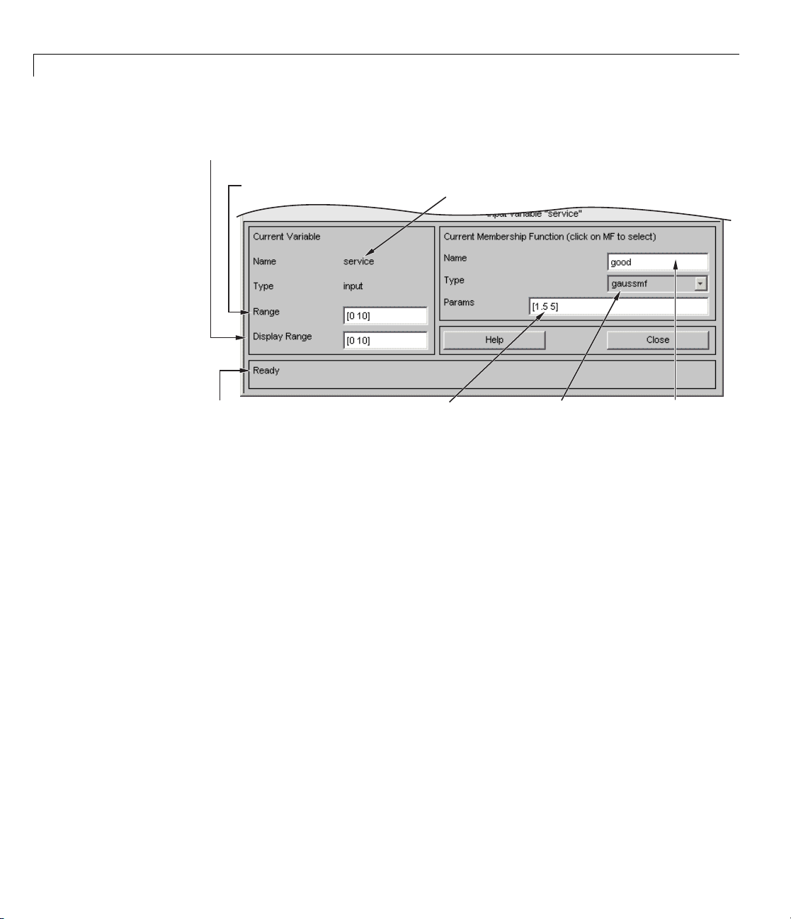
2 Tutorial
Set the display range
of the current plot.
Set the range
of the current variable.
This status line
describes the most
recent operation.
Change the numerical
parameters for current
membership function.
Name and type of
current variable.
Select the type of
current membership
function.
Edit name of current
membership function.
When you open the Membership Function Editor to work on a fuzzy inference
system that does not already exist in the workspace, there are no membership
functions associated with the variables that you defined with the FIS Editor.
On the upper-left side of the graph area in the Membership Function Editor is
a “Variable Palette” that lets you set the membership functions for a given
variable.
2-42
To set up the me mbership functions associated with an input or an output
variable for the FIS, select a FIS variable in this region by clicking it.
Next select the Edit pull-down menu, and choose Add MFs ..Anewwindow
appears, which a ll ows you to select both the membership function type and
the number of membership functions associated with the selected variable.
In the lower-right corner of the window are the controls that let you change
the name, type, and parameters (shape), of the membership function, after
it is selected.
The membership functions from the current variable a re displayed in the main
graph. These membership functions can be manipulated in two ways. You
Page 73

Building Systems with Fuzzy Logic Toolbox™ Software
can first use the mouse to select a particular membership function associated
with a given variable quality, (such as poor, for the variable, service), and
then drag the membership function from side to side. This action affects the
mathematical description of the quality associated with that membership
function for a given variable. The selected membership function can also be
tagged for dilation or contraction by clicking on the small square drag points
on the membership function, and then dragging the function with the mouse
toward the outside, for dilation, or toward the inside, for contraction. This
action changes the parameters associated with that membership function.
Below the Variable Palette is some information about the type and name of
the current variable. There is a text field in this region that lets you change
the limits of the current variable’s range (universe of discourse) and another
that lets you set the limits of the current plot (which has no real effect on
the system).
The p rocess of specify ing the membership functions for the two input tipping
example,
tipper,isasfollows:
1 Double-click the input variable service to open the Membership Function
Editor.
2-43
Page 74

2 Tutorial
2-44
2 In the Membership Function Editor, enter [0 10] in the Range and the
Display Range fields.
3 Create
a Select
funct
b Selec
c In th
Type
membership functions for the input variable
Edit > Remove All MFs to remove the default membership
ions for the input variable
service.
t Edit > Add MFs. to open the Mem be rship Functions dialog box.
e Membership Functions dialog box, select
.
service.
gaussmf as the MF
Page 75

Building Systems with Fuzzy Logic Toolbox™ Software
d Verify that 3 is selected as the Number of MFs.
e Click OK to add three Gaussian curves to the input variable service.
4 Rename the membership functions for the input variable service,and
specify their parameters.
a Click on the curve named mf1 to select it, and specify the following fields
in the Current Membersh ip Function (click on MF to select) area:
• In the Name field, enter
• In the Params field, enter
poor.
[1.5 0].
The two inputs of Params represent the standard deviation and
center for the Gaussian curve.
Tip To adjust the shape of the membership function, type in a desired
parameters or use the mouse, as described previously.
The Membership Function Editor: tipper window looks similar to
the following figure.
2-45
Page 76
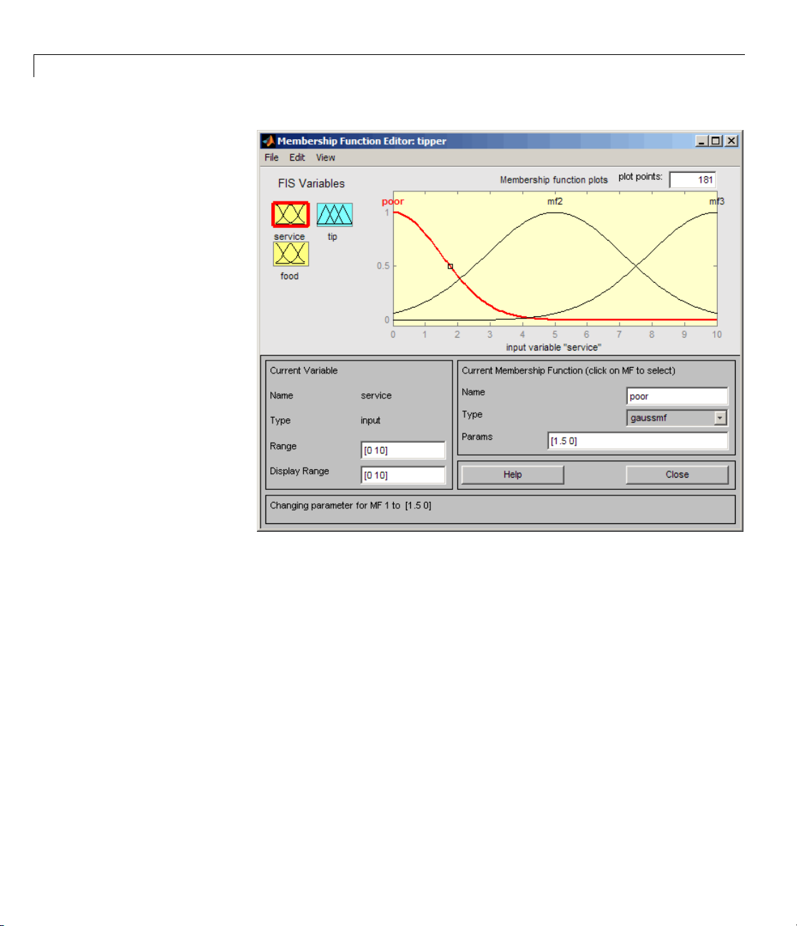
2 Tutorial
2-46
b Click on the curve named mf2 to select it, and specify the following fields
in the Current Membersh ip Function (click on MF to select) area:
• In the Name field, enter
• In the Params field, enter
c Click on the curve named mf3, and specify the following fields in the
good.
[1.5 5].
Current M embership Function (click on M F to select) area:
• In the Name field, enter
• In the Params field, enter
excellent.
[1.5 10].
The Membership Function Editor window looks similar to the following
figure.
Page 77

Building Systems with Fuzzy Logic Toolbox™ Software
5 In the FIS Variables area, click the input variable food to select it.
010]
6 Enter [
7 Create the membership functions for the input variable food.
a Select Edit > Remove All MFs to remove the default Membership
Functions for the input variable
b Select Edit > Add MFs to open the Membership Functions dialog box.
c In the Membership Functions dialog box, select trapmf as the MF Type.
d Select 2 in the Number of MFs drop-down list.
e Click OK to add two trapezoidal curves to the input variable food.
in the Range and the Display Range fields.
food.
2-47
Page 78

2 Tutorial
8 Rename the membership functions for the input variable food,andspecify
their parameters:
a In the FIS Variables area, click the input variable food to select it.
b Click on the curve named mf1, and specify the following fields in the
Current M embership Function (click on M F to select) area:
• In the Name field, enter
• In the Params field, enter
c Click on the curve named mf2 to select it, and enter delicious in the
rancid.
[0 0 1 3].
Name field.
Reset the associated parameters if desired.
9 Click on the output variable tip to select it.
10 Enter [0 30] in the Range and the Display Range fields to cover the
output range.
The inputs ranges from 0 to 10, but the output is a tip between 5% and 25%.
11 Rename the default triangular membership functions for the output
variable
a Click the curve named mf1 to select it, and specify the following fields in
tip, and specify their parameters.
the Current Membership Function (click on MF to select) area:
• In the Name field, enter
• In the Params field, enter
b Click the curve named mf2 to select it, and specify the following fields in
cheap.
[0 5 10].
the Current Membership Function (click on MF to select) area:
2-48
• In the Name field, enter
• In the Params field, enter
c Click the curve named mf3 to select it, a nd specify the following:
• In the Name field, enter
• In the Params field, enter
average.
[10 15 20].
generous.
[20 25 30].
The Membership Function Editor looks similar to the following figure.
Page 79

Building Systems with Fuzzy Logic Toolbox™ Software
Now that the variables have been named and the membership functions
have appropriate shapes and names, you can enter the rules. To call up the
RuleEditor,gototheEdit menu and select Rules,ortype
ruleedit at the
command line.
2-49
Page 80

2 Tutorial
The Rule Editor
The menu items allow
you to save, open, or
edit a fuzzy system
using any of the five
basic GUI tools.
Link input
statements in rules.
Input or output selection menus.
The rules are
entered
automatically
using the GUI
tools.
2-50
This status line
describes the most
recent operation.
Negate input or output
statements in rules.
Create or edit rules with the GUI buttons and
choices from the input or output selection menus.
The Help button
gives some
information about
how the Rule Editor
works, and the
Close button closes
the window.
Constructing rules using the graphical Rule Editor interface is fairly self
evident. Based on the descriptions of the input and output variables defined
with the FIS Editor, the Rule Editor allows you to construct the rule
statements automatically, From the GUI, you can:
• Create rules by selecting an item in each input and output variable box,
selecting one Connection item, and clicking Add Rule. You can choose
Page 81

Building Systems with Fuzzy Logic Toolbox™ Software
none as one of the variable qualities to exclude that variable from a given
rule and choose
not under any variable name to negate the associated
quality.
• Delete a rule by selecting the rule and clicking Delete Rule.
• Edit a rule by changing the selection in the variable box and clicking
Change Rule.
• Specify weight to a rule by typing in a desired number betwee n
Weight. If you do not specify the weight, it is assumed to be unity
0 and 1 in
(1).
Similar to those in the FIS Editor and the Membership Function Editor, the
Rule Editor has the menu bar and the status line. The menu items allow
you to open, close, save and edit a fuzzy system using the five basic GUI
tools. From the menu, you can also:
• Set the format for the display by s electing Options > Format.
• Set the language by selecting Options > Language.
You can access information abouttheRuleEditorbyclickingHelp and c lose
the GUI using Close.
To insert the first rule in the Rule Editor, select the following:
•
poor under the variable service
rancid under the variable food
•
• The or radio button, in the Connection block
cheap, under the output variable, tip.
•
Then, click Add rule.
The resulting rule is
1. If (service is poor) or (food is rancid) then (tip is cheap) (1)
The numbers in the parentheses represent weights.
Follow a similar procedure to insert the seco nd and third rules in the Rule
Editor to get
2-51
Page 82

2 Tutorial
1 If (service is poor) or (food is rancid) then (tip is cheap) (1)
2 If (service is good) then (tip is average) (1)
3 If (service is excellent) or (food is delicious) then (tip is generous) (1)
Tip To change a rule, first click on theruletobechanged. Nextmakethe
desired changes to that rule, and then click Change rule. For example, to
change the first rule to
1. If (service not poor) or (food not rancid) then (tip is not cheap) (1)
Select the not check box under each variable, and then click Change rule.
The Format pop-up menu from the Options menu indicates that you are
looking at the verbose form of the rules. Try changing it to
symbolic.You
will see
2-52
1. (service==poor) | (food==rancid) => (tip=cheap) (1)
2. (service==good) => (tip=average) (1)
3. (service==excellent) | (food==delicious) => (tip=generous) (1)
There is not much difference in the display really, but it is slightly more
language neutral, because it does not depend on terms like if and then.If
you change the format to indexed, you see an extremely compressed version
of the rules.
11,1(1): 2
20,2(1): 1
32,3(1): 2
This is the version of the rules that the machine deals with.
• The first column in this structure corresponds to the input variables.
• The second column corresponds to the output variable.
• The third column displays the weight a pplie d to each rule.
• The fourth column is shorthand that indicates whether this is an OR (2)
rule or an AND (1) rule.
Page 83

Building Systems with Fuzzy Logic Toolbox™ Software
• The numbers in the first two columns refer to the index number of the
membership function.
A literal interpretation of rule 1 is “If input 1 is MF1 (the first m em b ersh ip
function associated with input 1) or if input 2 is MF1, then output 1 should
be MF1 (the first membership function associated with o utput 1) with the
weight 1.
The symbolic format does not consider the terms, if, then, and so on. The
indexed format doesn’t even bother with the names of your variables.
Obviously the functionality of your system doesn’t depend on how well you
have named your variables and membership functions. The whole point of
naming variables descriptively is, as always, making the system easier for
you to interpret. Thus, unless you have some special purpose in mind, it is
probably be easier for you to continue with the verbose format.
At this point, the fuzzy inference system has been completely defined, in that
the variables, membership functions, and the rules necessary to calculate tips
are in place. Now, look at the fuzzy inference diagram pres ented at the end of
the previous section and verify that everything is behaving the way you think
itshould. YoucanusetheRuleViewer,thenextoftheGUItoolswe’lllookat.
From the View menu, select Rules.
2-53
Page 84

2 Tutorial
The Rule Viewer
2-54
TheRuleViewerdisplaysaroadmapofthe whole fuzzy inference process . It
is based on the fuzzy inference diagram described in the previous section. You
see a single figure window with 10 plots nested in it. The three plots across
the top of the figure represent the antecedent and consequent of the first rule.
Each rule is a row of plots, and each column is a variable. The rule numbers
are displayed on the left of each row. You can click on a rule number to view
the rule in the status line.
• Thefirsttwocolumnsofplots(thesixyellow plots) show the membership
functions referenced by the antecedent, or the if-part of each rule.
• The third column of plots (the three blue plots) shows the mem bership
functions referenced by the consequent, or the then-part of each rule.
Page 85

Building Systems with Fuzzy Logic Toolbox™ Software
Notice that under food, there is a plot which is blank. This corresponds to
the characterization of
none for the variable food in the second rule.
• The fourth plot in the third c olumn of plots represents the aggregate
weighted decision for the given inference system.
This decision will depend on the input values for the system. The
defuzzified output is displayed as a bold vertical line on this plot.
The variables and their current values are displayed on top of the columns. In
the lower left, there is a text field Input in which you can enter specific input
values. For the two-input system, you will enter an input vector,
[9 8],for
example, and then press Enter. Youcanalsoadjusttheseinputvaluesby
clicking on any of the three plots for each input. This will move the red index
line horizontally, to the point where you have clicked. Alternatively, you can
also click and drag this line in order to change the input values. When you
release the line, (or after manually specifying the input), a new calculation is
performed, and you can see the whole fuzzy inference process take place:
• Where the index line representing service crosses the membership function
line “service is poor” in the upper-left plot determines the degree to which
rule one is activated.
• A yellow patch of color under the actual membership function curve is used
to make the fuzzy membership value visually apparent.
Each o f the characterizations of each of the variables is specified with respect
to the input index line in this manner. If you follow rule 1 across the top of
the diagram, you can see the consequent “tip is cheap” has been truncated to
exactly the same degree as the (composite) anteceden t —this is the implication
process in action. The aggregation occurs down the third column, and the
resultant aggregate plot is shown in the single plot appearing in the lower
right corner of the plot field. The defuzzified output value is shown by the
thick line passing through the aggregate fuzzy se t.
You can shift the plots using left, right, down,andup.Themenuitemsallow
you to save, open, or edit a fuzzy system using any of the five basic GUI tools.
The Rule Viewer allows you to interpret the entire fuzzy inference process
at once. The Rule Viewer also shows how the shape of certain membership
functions influences the overall result. Because it plots every part of every
2-55
Page 86

2 Tutorial
rule, it can become unwieldy for particularly large systems, but, for a
relatively small number of inputs and outputs, it performs well (depending on
how m uch screen space you devote to it) with up to 30 rules and as many as
6 or 7 variables.
The Rule Viewer shows one calculation at a time and in great detail. In this
sense, it presents a sort of micro view of the fuzzy inference system. If you
want to see the entire output surface of your system—the e ntire span of the
output set based on the entire span of the input set—you need to open up the
Surface Viewer. This viewer is the last of the five basic Fuzzy Logic Toolbox
GUI tools. To open the Surface Viewer, select Surface from the View menu.
The Surface Viewer
2-56
Page 87

Building Systems with Fuzzy Logic Toolbox™ Software
Upon opening the Surface Viewer, you see a three-dimensional curve that
represents the mapping from food and service quality to tip amount. Because
this curve represents a two-input one-output case, you can see the entire
mapping in one plot. When we move beyond three dimensions overall, we
start to encounter trouble displaying the results.
Accordingly, the Surface Viewer is equipped with drop-down menus X
(input):, Y(input): and Z(output): that let you select any two inputs
and any one output for plotting. Below these menus are two input fields X
grids: and Ygrids: that let you specify how many x-axis and y-axis grid
lines you want to include. This capability allows you to keep the calculation
time reasonable for complex problems.
If you want to create a smoother plot, use the Plot points field to specify the
number of points on which the membership functions are evaluated in the
input or output range. By default, th e value of this field is 101.
Clicking Evaluate initiates the calculation, and the plot is generated after
the calculation is complete. To change the x-axis or y-axis grid after the
surface is in view, change the appropriate input field, and press Enter.The
surface plot is updated to reflect the new g rid settings.
The Surface Viewer has a special capability that is very helpful in cases with
two (or more) inputs and one output: you can grab the axes, using the mouse
and reposition them to get a different three-dimensional view on the data.
The Ref. Input field is used in situations when there are more inputs
required by the system than the surface is m apping. You can edit this field to
explicitly set inputs not specified in the surface plot.
Suppose you have a four-input one-output system and would like to see the
output surface. The Surface Viewer can generate a three-dimensional output
surface where any two of the inputs vary, but two of the inputs must be held
constant because computer monitors cannot display a five-dimensional shape.
In such a case, the input is a four-dimensional vector with
NaNsholdingthe
place of the varying inputs while numerical values indicates those values that
remain fixed. A NaN is the IEEE
®
symbol for Not a Number.
2-57
Page 88

2 Tutorial
The menu items allow you to open, close, save and edit a fuzzy system using
the five basic GUI tools. You can access information about the Surface Viewer
by clicking Help and close the GUI using Close.
This concludes the quick walk-through of each of the main GUI tools. For the
tipping problem, the output of the fuzzy system matches your original idea of
the shape of the fuzzy mapping from service to tip fairly well. In hindsight,
you might say, “Why bother? I could have just drawn a quick lookup table
and been done an hour ago!” How eve r, if you are interested in solving an
entire class of similar decision-making problems, fuzzy logic may provide
an appropriate tool for the solution, given its ease with which a system can
be quickly modified.
Importing and Exporting from the GUI Tools
When you save a fuzzy system to a file, you are saving an ASCII text FIS file
representation of that system with the file suffix
edited and modified and is simple to understand. When you save your fuzzy
system to the MATLAB workspace, you are creating a variable (whose name
you choose) that acts as a MATLAB structure for the FIS system. FIS files
and FIS structures represent the same system.
.fis. This text file can be
2-58
Note If you do not save your FIS to a file, but only save it to the MATLAB
workspace, y ou cannot recover it for use in a new MATLAB session.
Page 89

Building Fuzzy Inference Systems Using Custom Functions
Building Fuzzy Inference Systems Using Custom Functions
In this section...
“How to Build Fuzzy Inference Systems Using Custom Functions in the
GUI” on page 2-59
“Specifying Custom Membership Functions” on page 2-61
“Specifying C ustom Inference Functions” on page 2-67
How to Build Fuzzy Inference Systems Using Custom
Functions in the GUI
When you build a fuzzy inference system, as described in “Overview of Fuzzy
Inference Process” on page 2-21, you can replace the built-in membership
functions or inference functions, or both with custom functions. In this
section, you learn how to b uild a fuzzy inference system using custom
functions in the GUI. To learn how to build the system using custom functions
at the command line, see “Specifying Custom Membership and Inference
Functions” on page 2-82 in “Working from the Command Line” on page 2-73.
To build a fuzzy inference system using custom functions in the GUI:
1 Open the FIS Editor by typing fuzzy at the MATLAB prompt.
2 Specify the number of inputs and outputs of the fuzzy system, as described
in “The FIS Editor” on page 2-35.
3 Create custom membership functions, and replace the built-in membership
functions with them, as described in “Specifying Custom Membership
Functions” on page 2-61.
Membership functions define h ow each point in the input space is mapped
to a membership value between 0 and 1.
4 Create rules using the Rule Editor, as described in “The Rule Editor” on
page 2-50.
Rules define the logical relationship between the inputs and the outputs.
2-59
Page 90

2 Tutorial
5 Create custom inference functions, and replace the built in inference
functions with them, as described in “Specifying Custom Inference
Functions” on page 2-67.
Inference methods include the AND, OR, implication, aggregation and
defuzzification methods. This action generates the output values for the
fuzzy system.
The next figure shows the tipping problem example where the built-in
Implication and Defuzzification functions are replaced with a custom
implication function,
customdefuzz,respectively.
customimp, and custom defuzzification function,
2-60
ect View > Surface to view the output of the fuzzy inference system in
6 Sel
Surface Viewer, as described in “The Surface Viewer” on page 2-56.
the
Page 91

Building Fuzzy Inference Systems Using Custom Functions
Specifying Custom Membership Functions
You can create custom membership functions, and use them in the fuzzy
inference process. The values of these functions must lie between 0 and 1. You
must save the custom membership functions in your current working folder.
To learn how to build fuzzy systems using custom membership functions,
see “How to Build Fuzzy Inference Systems Using Custom Functions in the
GUI” on page 2-59.
To create a custom membership function, and replace the built-in membership
function:
1 Create a MATLAB function, and save it in your current working folder.
To learn how to create MATLAB functions, see the “Functions and Scripts”
section in the MATLAB documentation.
The following code is an example of a multi-step custom membership
function,
% Function to generate a multi-step custom membership function
% using 8 parameters for the input argument x
function out = custmf1(x, params)
for i=1:length(x)
if x(i)<params(1)
elseif x(i)<params(2)
elseif x(i)<params(3)
elseif x(i)<params(4)
elseif x(i)<params(5)
elseif x(i)<params(6)
elseif x(i)<params(7)
elseif x(i)<params(8)
else
custmf1, that depends on eight parameters between 0 and 10.
y(i)=params(1);
y(i)=params(2);
y(i)=params(3);
y(i)=params(4);
y(i)=params(5);
y(i)=params(6);
y(i)=params(7);
y(i)=params(8);
2-61
Page 92

2 Tutorial
y(i)=0;
end
end
out=.1*y'; % scaling the o utp ut to lie between 0 and 1
Note Custom membership functions can include a maximum of 16
parameters for the input argument.
2 Open the FIS Editor by typing fuzzy at the MATLAB prompt, if you have
notdonesoalready.
The FIS Editor opens with the default FIS name,
one input input1, and one output output1.
Untitled, and contains
2-62
Page 93

Building Fuzzy Inference Systems Using Custom Functions
3 In the F IS Editor, select Edit > Membership Functions to open the
Membership Function Editor.
Three triangular-shaped membership functions for input1 are displayed
by default.
4 To replace the default membership function with a custom function in
the Membership Function Editor:
a Select Edit > Remove All MFs to remove the default membership
functions for input1.
2-63
Page 94

2 Tutorial
b Select Edit > Add Custom MF to open the Custom Membership
Function dialog box.
5 To specify a custom function in the Custom Membership Function dialog
box:
a Specify a name for the custom membership function in the MF name
field.
2-64
Note When adding additional custom membership functions, you must
specify a different MF name for each function.
b Specify the name of the custom membership function file in the M-file
function name field.
c Specify a vector of parameters in the Parameter list field.
These
func
Note
to t
valuesdeterminetheshapeandpositionofthemembership
tion, and the function is evaluated using these parameter values.
The length of the parameter vector must be greater than or equal
he number of parameters in the custom membership function.
Page 95

Building Fuzzy Inference Systems Using Custom Functions
Using the custmf1 example in step 1, the Custom Membership Function
dialog box looks similar to the following figure.
d Click OK to add the custom membership function.
The Membership Function E ditor displays the custom membership function
plot.
2-65
Page 96

2 Tutorial
2-66
This action also adds the custom membership function to the Rule Viewer,
and is now available for creating rules for the fuzzy inference process. To
view the custom function in the Rule Viewer, select Edit > Rules in either
the FIS Editor or the Membership Function Editor.
Page 97
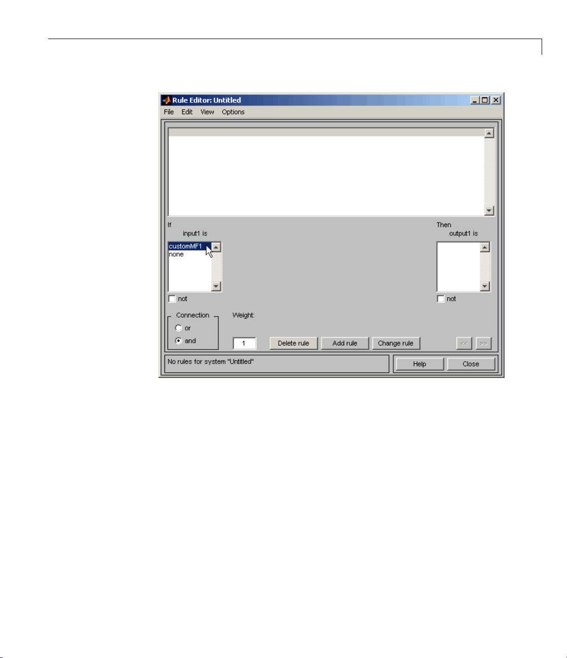
Building Fuzzy Inference Systems Using Custom Functions
6 To add custom membership functions for output1, select it in the
Membership Function Editor, and repeat steps 4 and 5.
Specifying Custom Inference Functions
You can replace the built-in AND, OR, imp li cati on, aggregation, and
defuzzification inference methods with custom functions. After you create the
custom inference function, save it in your current working folder. To learn
how to build fuzzy systems using custom inference functions, see the “How
to Build Fuzzy Inference Systems Using Custom Functions in the GUI” on
page 2-59 section.
You must follow a few guidelines when creating custom inference functions.
The guidelines for creating and specifying the functions for building fuzzy
inference systems are described in the following sections.
2-67
Page 98

2 Tutorial
• “Guidelines for Creating Custom AND and OR Functions” on page 2-68
• “Guidelines for Creating Custom Implication Functions” on page 2-69
• “Guidelines for Creating Custom Aggregation Functions” on page 2-69
• “Guidelines for Creating Custom Defuzzification Functions” on page 2-70
• “Steps for Specifying Custom Inference Functions” on page 2-70
Guidelines for Creating Custom AND and OR Functions
The custom AND and OR inference functions must operate column-wise on a
matrix, in the same way as the MATLAB functions
max, min,orprod.
For a row or column matrix
x=[1 2 3 4];
min(x)
ans =
1
x, min(x) returns the minimum element.
For a matrix x, min( x) returns a row vector containing the minimum element
from each column.
x=[1 2 3 4;5 6 7 8;9 10 11 12];
min(x)
ans =
1234
For N -D arrays, m in(x) operates along the first non-singleton dimension.
The function
minimum elements from
Functions such as
min(x,y) returns an array that is same size as x and y with the
x or y. Either of the input arguments can be a scalar.
max,andprod operate in a similar manner.
2-68
Page 99

Building Fuzzy Inference Systems Using Custom Functions
In the toolbox, the AND implication methods perform an element by element
matrix operation, similar to the MATLAB function
a=[1 2; 3 4];
b=[2 2; 2 2];
min(a,b)
ans =
12
22
min(x,y).
The OR implication methods perform an element by element matrix operation,
similar to the MATLAB function
max(x,y).
Guidelines for Creating Custom Implication Functions
The custom implication functio n s must operate in the same way as
the MATLAB functions
custom_imp(w,outputmf)
Here w is an nr-by-ns matrix and contains the weight of each rule. nr is the
number of rules, and ns isthenumberofparametersusedtodefinethe
output membership functions. w(:,j) = w(:,1) for all j,andw(i,1) is the firing
strength of the i
th
max, min,orprod and must be of the form y=
.
rule.
outputmf is an nr-by-ns matrix and contains the data for each output
membership function, where the i
th
row is the data for the ithoutput
membership function.
The following is an example of a custom implication function:
function impfun = custom_ imp(w,outputmf)
impfun = min(w,outputmf);
Guidelines for Creating Custom Aggregation Functions
The custom aggregation functions must operate in the same way as
the MATLAB functions
custom_agg(x)
.
x is an nv-by-nr matrix, which is the list of truncated output functions
returned by the implication method for each rule. nv is the number of output
max, min,orprod and must be of the form y=
2-69
Page 100

2 Tutorial
variables, and nr is the number of rules. The output of the aggregation
method is one fuzzy set for each output variable.
The following is an example of a custom aggregation function:
function aggfun = custom_ agg(x)
aggfun=(sum(x)/2).^0.5;
Guidelines for Creating Custom Defuzzification Functions
The custom defuzzification functions must be o f the form y=
custom_defuzz(xmf,ymf)
function values. xmf is the vector of values in the membership function input
range. ymf is the value of the membership function at xmf.
The following is an example of a custom defuzzification function:
function defuzzfun= custom_defuzz(xmf,ymf);
total_area=sum(ymf);
defuzzfun=sum(ymf*xmf)/total_area;
,where(xmf,ymf) is a finite set of membership
2-70
Steps for Specifying Custom Inference Functions
After you create and save a custom inference function, use the following steps
to specify the function in the fuzzy inference process:
 Loading...