

Page 1

Filter Design HDL Coder™
Release Notes
Page 2
How to Contact The MathWorks
www.mathworks.
comp.soft-sys.matlab Newsgroup
www.mathworks.com/contact_TS.html Technical Support
suggest@mathworks.com Product enhancement suggestions
bugs@mathwo
doc@mathworks.com Documentation error reports
service@mathworks.com Order status, license renewals, passcodes
info@mathwo
com
rks.com
rks.com
Web
Bug reports
Sales, prici
ng, and general information
508-647-7000 (Phone)
508-647-7001 (Fax)
The MathWorks, Inc.
3 Apple Hill Drive
Natick, MA 01760-2098
For contact information about worldwide offices, see the MathWorks Web site.
Filter Design HDL Coder™ Release Notes
© COPYRIGHT 2005–20 10 by The MathWorks, Inc.
The software described in this document is furnished under a license agreement. The software may be used
or copied only under the terms of the license agreement. No part of this manual may be photocopied or
reproduced in any form without prior written consent from The MathW orks, Inc.
FEDERAL ACQUISITION: This provision applies to all acquisitions of the Program and Documentation
by, for, or through the federal government of the United States. By accepting delivery of the Program
or Documentation, the government hereby agrees that this software or documentation qualifies as
commercial computer software or commercial computer software documentation as such terms are used
or defined in FAR 12.212, DFARS Part 227.72, and DFARS 252.227-7014. Accordingly, the terms and
conditions of this Agreement and only those rights specified in this Agreement, shall pertain to and govern
theuse,modification,reproduction,release,performance,display,anddisclosureoftheProgramand
Documentation by the federal government (or other entity acquiring for or through the federal government)
and shall supersede any conflicting contractual terms or conditions. If this License fails to meet the
government’s needs or is inconsistent in any respect with federal procurement law, the government agrees
to return the Program and Docu mentation, unused, to The MathWorks, Inc.
Trademarks
MATLAB and Simulink are registered trademarks of The MathWorks, Inc. See
www.mathworks.com/trademarks for a list of additional trademarks. Other product or brand
names may be trademarks or registered trademarks of their respective holders.
Patents
The MathWorks products are protected by one or more U.S. patents. Please see
www.mathworks.com/patents for more information.
Page 3

Summary by Version ............................... 1
Version 2.6 (R2010a) Filter Design HDL Coder
Software
Version 2.5 (R2009b) Filter Design H DL Coder
Software
Version 2.4 (R2009a) Filter Design HDL Coder
Software
Version 2.3 (R2008b) Filter Design H DL Coder
Software
Version 2.2 (R2008a) Filter Design HDL Coder
Software
........................................ 5
........................................ 13
........................................ 21
........................................ 25
........................................ 29
Contents
Version 2.1 (R2007b) Filter Design H DL Coder
Software
Version 2.0 (R2007a) Filter Design HDL Coder
Software
Version 1.5 (R2006b) Filter Design H DL Coder
Software
Version 1.4 (R2006a) Filter Design HDL Coder
Software
Compatibility Summary for Filter Design HDL Coder
Software
........................................ 39
........................................ 49
........................................ 64
........................................ 72
........................................ 76
iii
Page 4

iv Contents
Page 5

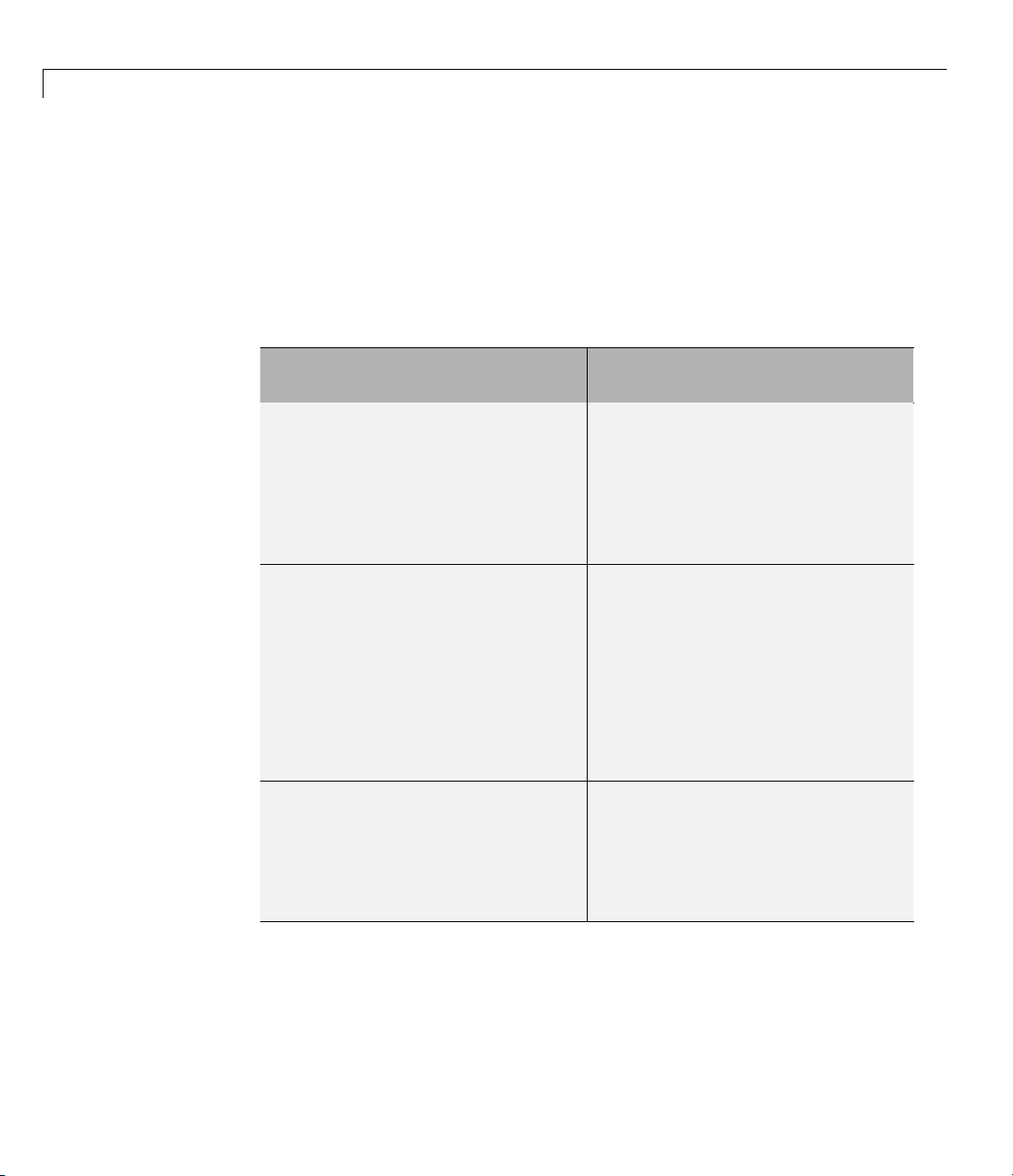
SummarybyVersion
This table provides quick access to what’s new in each version. For
clarification, see “Using Release Notes” on page 2 .
Filter Design HDL Coder™ Release Notes
Version
(Release)
Latest Versi
V2.6 (R2010a
V2.5 (R2009b)
V2.4 (R2009a)
V2.3 (R2
V2.2 (R2008a)
V2.1 (R2007b)
008b)
New Features
and Changes
on
Yes
)
Details
Yes
Details
Yes
Details
Yes
Details
Yes
Details
Yes
Deta
ils
Version
Compatibilit
Consideratio
Yes
Summary
Yes
Summary
Yes
Summary
Yes
Summary
Yes
Summary
Yes
Summ
ary
Fixed Bugs
y
and Known
ns
Problems
No
No No
No No
No No
No No
No No
Related
Documentation
at Web Site
YesPrintable
Release Notes:
PDF
Current product
documentation
0 (R2007a)
V2.
Yes
Details
No No No
1
Page 6
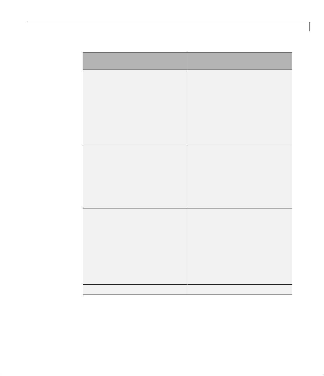
Filter Design HDL Coder™ Release Notes
Version
(Release)
V1.5 (R2006b)
V1.4 (R2006a)
New Features
and Changes
Yes
Details
Yes
Details
Version
Compatibility
Considerations
Yes
Summary
Yes
Summary
Fixed Bugs
and Known
Problems
Bug Reports No
Bug Reports No
Related
Documentation
at Web Site
Using Release Notes
Use release notes when upgrading to a newer version to learn about:
• New features
• Changes
• Potential impact on your existing files and practices
Review the release notes for other MathWorks™ products required for this
product (for example, MATLAB
bugs, or compatibility considerations in other products impact you.
®
or Simulink®). Determine if enhancements,
If you are upgrading from a software version other than the m ost recent one,
review the current release notes and all interim versions. For example, when
you upg rade from V1.0 to V1.2, review the release notes for V1.1 and V1.2.
What Is in the Release Notes
New Features and Changes
• New functionality
• Changes to existing functionality
2
Page 7

SummarybyVersion
Version Compatibility Con si derations
When a new feature or change introduces a reported incompatibility between
versions, the Compatibility Considerations subsection explains the
impact.
Compatibility issues reported after the product release appear under Bug
Reports at The MathWorks™ Web site. Bug fixes can sometimes result
in incompatibilities, so review the fixed bugs in Bug Reports for any
compatibility impact.
Fixed Bugs and Known Problems
The MathWorks offers a user-searchable Bug Reports database so you can
view Bug Reports. The development team updates this database at release
time and as more information becomes available. Bug Reports include
provisions for any known workarounds or file replacem ents. Information is
available for bugs existing in or fixed in Release 14SP2 or later. Information
is not avail able for all bugs in earlier releases.
Access Bug Reports using y our MathWorks Account.
About Functions an d Properties Being Removed
This section lists functions or properties removed or in the process of being
removed. Functions and properties typically go through several stages across
multiple releases before being completely removed. This provides time for you
to make adjustments to your code.
• Announcement — The release notes announce the planned removal, but
there are no functional changes; the function runs as it did before.
• Warning — When you run the function, it displays a warning message
indicating it will be removed in a future release; otherwise the function
runs as it did before.
• Error — When you run the function, it produces an error. The error
message indicates the function was removed and suggests a replacement
function, if one is available.
• Removal — When you run the function, it fails. The error message is the
standard message when MATLAB does not recognize an entry.
3
Page 8

Filter Design HDL Coder™ Release Notes
Functions and properties might be in a stage for one or more releases before
moving to another stage. Functions and properties are listed in the Functions
and Properties Being Removed section only when they enter a new stage
and their behavior changes. For example, if a function displayed a warning
in the previous release and errors in this release, it appears on the list. If it
continues to display a warning, it does not appear on the list because there
was no change between the releases.
Not all functions and properties go through all stages. For example, a
function’s impending removal might not be announced, but instead, the first
notification might be that the function displays a warning.
The release notes include actions you can take to mitigate the effects of
function or property removal, such as adapting your code to use a replacement
function.
4
Page 9

Version 2.6 (R2010a) Filter Design HDL Coder™ Software
Version 2.6 (R2010a) Filter Design HDL Coder Software
This table summarizes what’s new in Version 2.6 (R2010a).
New Features and
Changes
Yes
Details below
Version
Compatibility
Considerations
Yes—Details labeled
as Compatibility
Considerations,
below. See also
Summary.
New features and changes introduced in this version are:
• “Multiplier Input and Output Pipelining for FIR Filters” on page 5
• “Support for Partly Serial Architecture for FIR Decimators” on page 7
• “Enhancements for Serial Architectures” on page 7
• “GUI Support for Programmable FIR FIlter Coefficients” on page 9
• “Option to Suppress Reset Logic Generation for Shift Registers” on page 11
Fixed Bugs an d
Known Problems
No
Related
Documentation at
Web Site
Printable Release
Notes: PDF
Current product
documentation
• “GenerateCosimModel ’IN’ and ’MQ’ Property Values Removed” on page 12
Multiplier Input and Output Pipelining for FIR Filters
Release R2010a lets you specify generation of pipeline stages at multiplier
inputs or outputs for all FIR filter structures. Multiplier pipelining can help
you achieve significan tly higher clock rates. You can select input pipelining,
output pipelining, or both. You can also specify the desired number of pipeline
stages.
The following figure shows the new GUI options for multiplier pipelining
options. These are:
5
Page 10

Filter Design HDL Coder™ Release Notes
• Multiplier input pipeline: Enter the desired number of pipeline stages
to be added before each multiplier.
• Multiplier output pipeline: Enter the desired number of pipeline stages
to be added after each multiplier.
6
Page 11

Version 2.6 (R2010a) Filter Design HDL Coder™ Software
The coder enables the Multiplier input pipeline and Multiplier output
pipeline options when Coefficient multipliers is set to
Alternatively, you can specify the desired number of pipeline stages as
generatehdl property/value pairs as follows:
•
'MultiplierInputPipeline', nStages
• 'MultiplierOutputPipeline', nStages
Multiplier.
Support for Partly Serial Architecture for F IR
Decimators
Release R2010a lets you specify a partly serial architecture for FIR decimator
filters (
for detaile d information about parallel and serial architectures supported for
HDL code generation.
mfilt.firdecim ). See “Speed vs. Area Optim izations for FIR Filters”
Enhancements for Serial Architectures
When you select the Partly serial Architecture option, the Generate HDL
dialog box now displays additional information and data entry fields related
to serial partitioning, as shown in the following figure.
7
Page 12

Filter Design HDL Coder™ Release Notes
The Specified by pulldown menu lets you define the serial partitioning in
any the following ways:
• Directly specify a vector of integers having
N elements, where N is the
number of serial partitions. Each e lem ent of the vector specifies the length
of the corresponding partition.
8
Page 13

Version 2.6 (R2010a) Filter Design HDL Coder™ Software
• Specify the desired hardware folding factor ff, an integer greater than 1.
Given the folding factor, the coder computes the serial partition and the
number of multipliers.
• Specify the desired number of multipliers
1. Given the number of multipliers, the coder computes the serial partition
nmults, an integer greater than
and the folding factor.
See “Speed vs. Area Optimizations for FIR Filters” for detailed information
about parallel and serial architectures supported for HDL code generation.
The coder also provides the new
define an optimal serial partition for your filter.
hdlgetserialpartition function to help you
hdlgetserialpartition
calculates and displays an exhaustive table of SerialPartition values for
a given filter, with corresponding values of folding factor and number of
multipliers. See hdlgetserialpartition for further information.
GUI Support for Programmable FIR FIlter Coefficients
For FIR filters with serial architectures, the Coefficient memory pulldown
menu now supports generation of a register or RAM based interface for
loading coefficients. The following figure shows the Coefficient memory
pulldown menu.
9
Page 14

Filter Design HDL Coder™ Release Notes
10
For detailed information, see “Specifying Programmable Filter Coefficients
for FIR Filters” in the F ilter Design HDL Coder™ documentation.
Page 15
Version 2.6 (R2010a) Filter Design HDL Coder™ Software
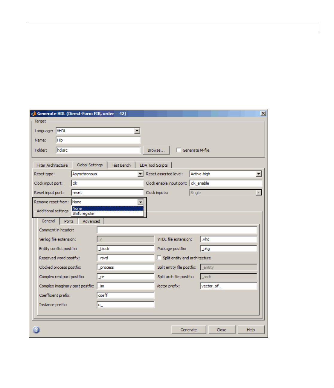
Option to Suppress Reset Logic Generation for Shift
Registers
R2010a lets you suppress generation of reset logic for shift registers. To
suppress reset logic, select
pulldown in the Global Settings pane of the Generate HDL dialog box, as
shown in the following figure.
Shift register from the Remove reset from
11
Page 16
Filter Design HDL Coder™ Release Notes
You can also use generatehdl function with the property RemoveResetFrom
to suppress generation of resets from shift registers.
GenerateCosimModel ’IN’ and ’MQ’ Property Values
Removed
Release R2010a no longer supports the 'IN' and 'MQ' property values. Use
the equivalent property values
in the following table.
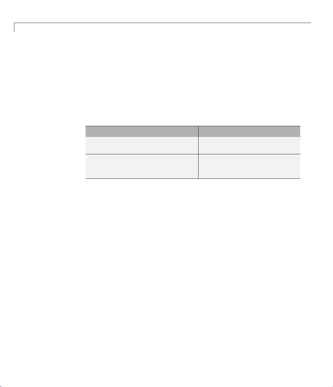
Current Property Value Deprecated Property Value
generatehdl(filterObj,
'GenerateCosimModel','
generatehdl(filterObj,
'GenerateCosimModel','
);
'Incisive' and 'ModelSim’, as summarized
generatehdl(filterObj,
Incisive’ );
ModelSim’
'GenerateCosimModel','IN’ );
generatehdl(filterObj,
'GenerateCosimModel','
MQ’ );
12
Compatibility Considerations
Replace any occurrences of ’IN’ and ’MQ’ in your control files and scripts
with the new property values ’Incisive’ and ’ModelSim’. In R2010a, the coder
raises an error a warning if it encounters the old property values during code
generation.
Page 17

Version 2.5 (R2009b) Filter Design HDL Coder™ Software
Version 2.5 (R2009b) Filter Design HDL Coder Software
This table summarizes what’s new in Version 2.5 (R2009b).
New Features and
Changes
Yes
Details below
Version
Compatibility
Considerations
Yes—Details labeled
as Compatibility
Considerations,
below. See also
Summary.
New features and changes introduced in this version are:
• “Graphical User Interface Improved and Revised” on page 13
• “Test Bench GUI Reorganized” on page 15
• “GenerateCosimModel ’IN’ and ’MQ’ Property Values Replaced” on page 17
• “Extended Complex Data Type Support” on page 18
• “Generation of Model for Cosimulation Now Supports Multirate Filters”
on page 19
Fixed Bugs an d
Known Problems
No
Related
Documentation at
Web Site
Printable Release
Notes: PDF
Current product
documentation
• “RAM Based Programmable Coefficients Supported for FIR Filters with
Serial Architectures” on page 20
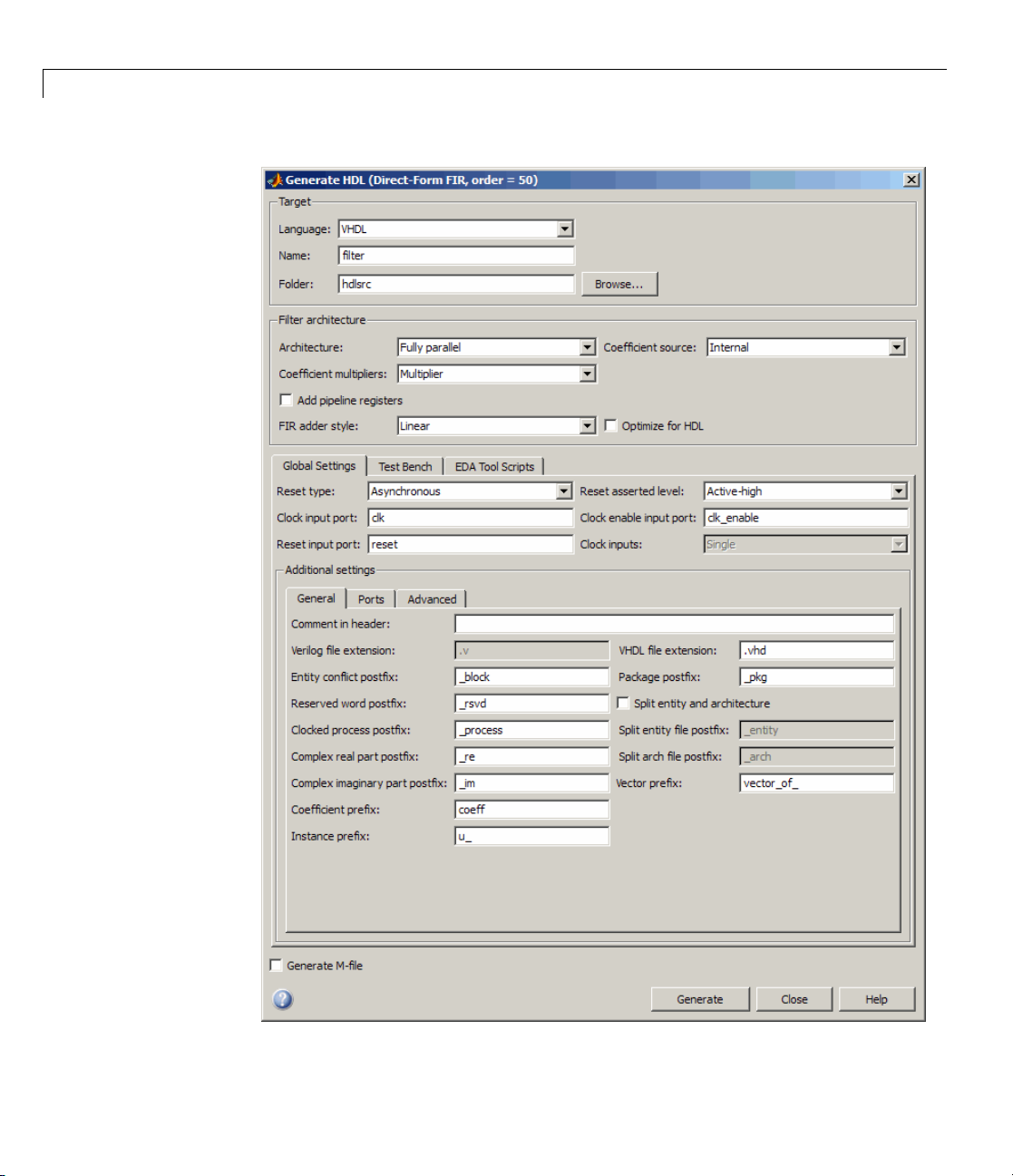
Graphical User Interface Improved and Revised
R2009b includes an improved and revised Filter Design HDL Coder graphical
user interface (GUI). The GUI now supports all functions within a single
dialog box. The following figure shows the Generate HDL dialog box.
13
Page 18
Filter Design HDL Coder™ Release Notes
14
Page 19
Version 2.5 (R2009b) Filter Design HDL Coder™ Software
Compatibility Considerations
Some property labels have changed in the new GUI. The following tale lists
the previous and current property labels.
Previous Property Label Current Property Label
Language
Folder Target directory
Filter target language
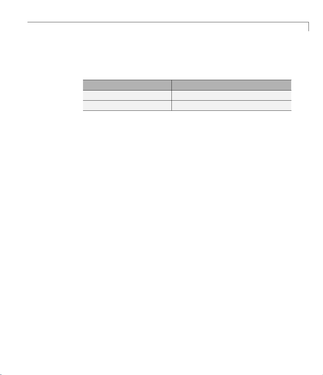
Test Bench GUI Reor ganized
The following figure shows the reorganized Test bench pane of the Generate
HDL dialog box.
15
Page 20
Filter Design HDL Coder™ Release Notes
16
Page 21
Version 2.5 (R2009b) Filter Design HDL Coder™ Software
The new Testbench generation output section contains three options:
• HDL test bench: Selecting this option enables generation of an HD L
test bench, and also enables all options in the Configuration section of
the Test Bench pane.
• Cosimulation blocks: Selecting this option enables Generate a model
containing HDL Cosimulation block(s) for use in testing the DUT. Selecting
this option also enables all options in the Configuration section o f the
Test Bench pane.
• Cosimulation model for use with: Selecting this option enables
generation of a model containing an HDL Cosimulation block for use in
testing the DUT, and lets you select the desired cosimulation tool. Selecting
this option also enables all options in the Configuration section o f the
Test Bench pane.
To configure test bench options and generate test bench code, you must select
one or more of the options of the Testbench generation output section. If
you deselect all three options of the Testbench generation output section,
the coder disables all options in the Configuration section of the Test
Bench pane.
GenerateCosimModel ’IN’ and ’MQ’ Property Values
Replaced
Release R2009b deprecates the 'IN' and 'MQ' property values. Use the
equivalent property values
the following table.
Current Property Value Deprecated Property Value
generatehdl(filterObj,
'GenerateCosimModel','
generatehdl(filterObj,
'GenerateCosimModel','
);
'Incisive' and 'ModelSim’, as summarized in
generatehdl(filterObj,
Incisive’ );
ModelSim’
'GenerateCosimModel','IN’ );
generatehdl(filterObj,
'GenerateCosimModel','
MQ’ );
17
Page 22
Filter Design HDL Coder™ Release Notes
Compatibility Considerations
Replace any occurrences of ’IN’ and ’MQ’ in your control files and scripts with
the new property values ’Incisive’ and ’ModelSim’. In R2009b, the coder issues
a warning if it encounters the old property values during code generation. In
subsequent releas es, use of the old property values will raise an error.
Extended Com plex Data Type Support
The coder now supports use of complex coefficients and complex input signals
for additional filter structures. In many cases, you can use complex data
and complex coefficients in combination. The following table shows the
added filter structures that support complex data and/or coefficients, and
the permitted combinations.
Filter Structure Complex
Data
dfilt.df1sos
dfilt.df1tsos
dfilt.df2sos
dfilt.df2tsos
mfilt.holdinterp
mfilt.firsrc
mfilt.firtdecim
YY Y
YY Y
YY Y
YY Y
YY
YY Y
YY Y
Complex
Coefficients
Complex Data
and Coefficients
N/A
The coder also supports use of complex data and complex coefficients in
combination for the
mfilt.firdecim and mfilt.firinterp filter structures.
Thefollowingtablesummarizescomplex data type support for these filter
structures.
Filter Structure Complex
Data
mfilt.firdecim
mfilt.firinterp
YY
YY
Complex
Coefficients
Complex Data
and Coefficients
Y (newly supported)
Y (newly supported)
18
Page 23

Version 2.5 (R2009b) Filter Design HDL Coder™ Software
For a list of filter structures supporting co m plex data, coefficients or both,
see “Using Complex Data and Coefficients” in the Filter Design HDL Coder
documentation.
Additional GUI Suppor t for Complex Data
R2009baddsthefollowingGUIoptionssupportinguseofcomplexdataand
coefficients.
• The Input complexity menu lets you select or disable generation of ports
and signal paths for the real and imaginary components of a complex signal.
The Input complexity setting defaults to
ports for complex input data. T o enable generation o f ports for co m plex
input data, set Input complexity to
• The Complex real part postfix option (corresponding to the
ComplexRealPostfix command-line property) specifies a string appended
to names generated for the real part of complex signals. The default postfix
is
'_re'.
• The Complex imaginary part postfix option (corresponding to the
ComplexImagPostfix command-line line property) specifies a string
appended to names generated for the imaginary part of complex signals.
The default postfix is
'_im'.
Real, disabling generation of
Complex.
Seealso“UsingComplexDataandCoefficients” in the Filter Design HDL
Coder documentation.
Generation of Model for Cosimulation Now Supports
Multirate Filters
The coder now supports generation of cosimulation m odels for multirate
filters. In previous releases, the coder supported generation of cosimulaton
models for single-rate models only.
See “Generating a Simulink M odel fo r Cosimulation with an HDL Si m ulator”
for further information.
19
Page 24

Filter Design HDL Coder™ Release Notes
RAM Based Programmable Coefficients Supported
for FIR Filters with Serial A rchitectures
For FIR filters with serial architectures, the coder now supports generation
of a single-port or dual-port RAM interface for loading coefficients. Previous
releases supported programmable coefficients stored in a register file.
For detailed information, see “Specifying Programmable Filter Coefficients
for F IR Filters” in the Filter Design HDL Coder documentation.
20
Page 25

Version 2.4 (R2009a) Filter Design HDL Coder™ Software
Version 2.4 (R2009a) Filter Design HDL Coder Software
This table summarizes what’s new in Version 2.4 (R2009a).
New Features and
Changes
Yes
Details below
Version
Compatibility
Considerations
Yes—Details labeled
as Compatibility
Considerations,
below. See also
Summary.
New features and changes introduced in this version are:
• “Complex Data Type Support for FIR, CIC, and Other Filter Structures”
on page 21
• “Generation of Simulink Model for Cosimulation of Generated HDL Code”
on page 23
• “Support for Programmable Coefficients for FIR Filters with Serial
Architectures” on page 23
• “Support for Programmable Coefficients for IIR Filters” on page 24
• “Default Entity C onflict Postfix Changed” on page 2 4
Fixed Bugs an d
Known Problems
No No
Related
Documentation at
Web Site
Complex Data Type Support for FIR, CIC, and Other
Filter Structures
The coder now supports use of complex coefficients and complex input signals
for fully parallel FIR, CIC, and some other filter structures. In many cases,
you can use complex data and complex coefficients in combination. The
following table shows the filter structures that support complex data and/or
coefficients, and the permitted combinations.
21
Page 26

Filter Design HDL Coder™ Release Notes
Filter Structure Complex
Data
dfilt.dffir
dfilt.dfsymfir
dfilt.dfasymfir
dfilt.dffirt
dfilt.scalar
dfilt.delay
mfilt.cicdecim
mfilt.cicinterp
mfilt.firdecim
mfilt.firinterp
mfilt.linearinterp
YY Y
YY Y
YY Y
YY Y
YY Y
Y
Y
Y
YY N
YY N
Y
Complex
Coefficients
Complex Data
and Coefficients
N/A N/A
N/A N/A
N/A N/A
N/A N/A
Properties Supporting Complex Data Types
The new InputComplex code generation property instructs the coder whether
or not to generate the appropriate ports and signal paths for the real and
imaginary components of a complex signal. To enable generation of ports for
complex input data, set
InputComplex 'on', as in the following code example:
22
Hd = design(fdesign.lowpass,'equiripple','Filterstructure','dffir');
generatehdl(Hd, 'InputComplex', 'on');
Two new code generation properties have been added to help you customize
naming conventions for the real and imaginary components of complex signals
in generated HDL code. The new properties are:
• The
ComplexRealPostfix property specifies a string to be appended to the
names generated for the real part of complex signals. The default postfix is
'_re'. See also ComplexRealPostfix.
• The
ComplexImagPostfix property specifies a string to be appended to the
names generated for the imaginary part of complex signals. The default
postfix is
'_im'. See also ComplexImagPostfix.
Page 27

Version 2.4 (R2009a) Filter Design HDL Coder™ Software
See “Using Complex Data and Coefficien t s” in the Filter Design HDL Coder
User’s Guide for complete details on complex data type support.
Generation of Simulink Model for Cosimulation of
Generated HDL Code
The coder supports gene ration of a Simulink model that is configured for:
• Simulink simulation of your filter design
• Cosimulation of your design with an HDL simulator
The generated model includes a behavioral model of the filter design, realized
in a Simulink subsystem, and a corresponding HDL Cosimulation block,
configured to cosimulate the filter design using Simulink. You can generate
an HDL Cosimulation block for either of the following EDA S imulator Link™
products:
• EDA Simulator Link (default)
• EDA Simulator Link
See “Generating a Simulink M odel fo r Cosimulation with an HDL Si m ulator”
for further information.
Support for Programmable Coefficients for FIR Filters
with Serial Architectures
For FIR filters with serial architectures, the coder now supports generation
of a memory interface for loading coefficients, and gene ration of testbench
coefficients to test the interface. In previous releases, these options were
supported only for fully parallel FIR filters.
Programmable coefficients are supported for all serial architecture options
(fully serial, partly serial, and cascade seria l) of the following direct-form
FIR filter types:
•
dfilt.dffir
• dfilt.dfsymfir
23
Page 28

Filter Design HDL Coder™ Release Notes
• dfilt.dfasymfir
For detailed information, see “Specifying Programmable Filter Coefficients
for FIR Filters” in the Filter Design HDL Coder User’s Guide.
Support for Programmable Coefficients for IIR Filters
For IIR filters, the coder now supports generation of a memory interface
for loading coefficients, and generation of testbench coefficients to test the
interface. In previous releases, this option was supported only for FIR filters.
The following IIR filter types support programmable filter coefficients:
• Second-order section (SOS) infinite impulse response (IIR) Direct Form I
(
dfilt.df1sos )
• SOS IIR D irect Form I transposed (
• SOS IIR Direct Form II (
• SOS IIR D irect Form II transposed (
For detailed information, see “Specifying Programmable Filter Coefficients
for IIR Filters” in the Filter Design HDL Coder documentation.
dfilt.df2sos)
dfilt.df1tsos)
dfilt.df2tsos)
Default Entity Conflict Postfix Changed
The default value for the Entity conflict postfix property (and the
corresponding CLI property,
from
'_entity' to '_block' .
Compatibility Considerations
If your scripts rely on the previous default value ('_entity')fortheEntity
conflict postfix property, you will need to explicitly se t the property value to
'_entity'.
EntityConflictPostfix) has been changed
24
Page 29

Version 2.3 (R2008b) Filter Design HDL Coder™ Software
Version 2.3 (R2008b) Filter Design HDL Coder Software
This table summarizes what’s new in Version 2.3 (R2008b).
New Features and
Changes
Yes
Details below
Version
Compatibility
Considerations
Yes—Details labeled
as Compatibility
Considerations,
below. See also
Summary.
New features and changes introduced in this version are:
• “Test Bench Enhancements” on page 25
• “Distributed Arithmetic Restriction Removed for Symmetrical and
Asymmetrical FIR Filters” on page 27
• “-novopt Flag Added to the Default Simulation Command in Generated
Compilation Scripts” on page 28
• “ModelSim .do T est Bench Option Removed” on page 28
Fixed Bugs an d
Known Problems
No No
Related
Documentation at
Web Site
Test Bench Enhancements
TheappearanceoftheMoreTestBenchSettings dialog box has been revised,
and a number of options have been added. The following figure shows the
default set of options in the More Test Bench Settings dialog box. Options
that have been added to the GUI are highlighted.
25
Page 30

Filter Design HDL Coder™ Release Notes
Each new option (except Setup time (ns)) has a corres ponding command-line
property. The following table lists the new options and their corresponding
command-line properties, and provides hyperlinks to the relevant
documentation.
GUI Option
Setup time (ns): See “Setting a Hold Time for
Data Input Signals” and “Configuring Resets”.
Clock enable delay (in clock cycles):See
“Configuring the Clock”.
26
Command-Line Property
This display-only field does not have a
corresponding user-settable command-line
property.
TestBenchClockEnableDelay
Page 31

Version 2.3 (R2008b) Filter Design HDL Coder™ Software
GUI Option
Reset length: See “Configuring Resets”.
Hold input data between samples:See
“Holding Input Data in a Valid State”.
Initialize test bench inputs: See “Setting an
Initial Value for Test Bench Inputs”.
Multi-file test bench: See “Splitting Test
Bench Code and Data into Separate Files”.
Test bench data file name postfix:See
“Splitting Test Bench Code and Data into
Separate Files”.
Test bench reference postfix: See “Setting
a P ostfix for Reference Signal Names”.
Generate cosimulation blocks:See
“Generating HDL Cosimulation Blocks for Use
with HDL Simulators”.
Distributed Arithmetic Restriction Removed for
Symmetrical and Asymmetrical FIR Filters
The DARadix property specifies the number of bits pro c esse d simultaneously in
a d istributed arithmetic architecture. In previous releases, when generating
code for symmetrical (
FIR filters, the
Specification of a
warning to be issued during code generation.
dfilt.dfsymfir) or asymmetrical (dfilt.dfasymfir)
DARadix value was required to be less than or equal to 2.
DARadix value greater than 2 for these filter types caused a
Command-Line Property
ResetLength
HoldInputDataBetweenSamples
InitializeTestBenchInputs
MultifileTestBench
TestBenchDataPostFix
TestBenchReferencePostFix
GenerateCoSimBlock
In Release 2008b, the coder permits use of
for these filter types. Other requirements for setting the
still apply. For details, see “DARadix Property” and “Considerations for
Symmetrical and Asymmetrical Filters” in the Filter Design HDL Coder
documentation.
For general information on distributed arithmetic support, se e “Distributed
Arithmetic for FIR Filters” in the Filter Design HDL Coder d ocu m en ta ti on.
DARadix values greater than 2
DARadix property
27
Page 32

Filter Design HDL Coder™ Release Notes
-novopt Flag Added to the Default Simulation
Command in Generated Compilation Scripts
For improved operation with the ModelSim®(Version 6.2 and late r) simulator,
the default values of the
Command GUI option) now includes the
'vsim -novopt work.%s\n'
The -novopt flag directs the ModelSim simulator not to perform optimizations
that remove signals from the simulatio n view.
Compatibility Considerations
If you are using ModelSim 6.0 or an earlier version, you should s et the
HDLSimCmd property string (or the Simulation Command GUI option) to
omit the
-novopt option, as follows:
'vsim work.%s\n'
HDLSimCmd property string (and the Simu lation
-novopt flag, as follows:
28
ModelSim .do Test B ench Option Removed
The Modelsim .do file test bench generation option, and the
corresponding
function, are no longer supported and have been removed from the current
release.
In the current release,
test bench generation if the
Compatibility Considerations
If your scripts use the 'Modelsim' test bench type argument for the
generatetb function, you should remove the 'Modelsim' argument. The test
bench type will then default to the current setting of the
property ('VHDL' or 'Verilog').
See also
'Modelsim' test bench type argument for the generatetb
generatetb displays an error message and terminates
'Modelsim' testbenchtypeoptionisspecified.
TargetLanguage
generatetb.
Page 33

Version 2.2 (R2008a) Filter Design HDL Coder™ Software
Version 2.2 (R2008a) Filter Design HDL Coder Software
This table summarizes what’s new in Version 2.2 (R2008a).
New Features and
Changes
Yes
Details below
Version
Compatibility
Considerations
Yes—Details labeled
as Compatibility
Considerations,
below. See also
Summary.
New features and changes introduced in this version are:
• “Code Generation Support for Multirate Farrow Sample Rate Converter
Filters” on page 29
• “Multifile Test Bench Generation” on page 30
• “Additional command-line Properties Supported” on page 30
• “GUI Support for Processor Interface for FIR Filter Coefficients” on page 30
• “generatetb Supports Default Specification of Test Bench Type” on page 33
• “Functions and Properties Being Removed” on page 33
• “ModelSim .do Test Bench Option Deprecated” on page 34
• “ScaleWarnBits Property No Longer Supported” on page 35
Fixed Bugs an d
Known Problems
No No
Related
Documentation at
Web Site
• “Summary of GUI Enhancements and Revisions” on page 35
Code Generation Support for Multirate Farrow
Sample Rate Converter Filters
The coder now supports HDL code generation for multirate Farrow sample
rate converter (
The coder also supports code generation for cascades that include a
mfilt.farrowsrc filter, provided that the mfilt.farrowsrc filter is in the
last position of the cascade.
mfilt.farrowsrc)filters.
29
Page 34

Filter Design HDL Coder™ Release Notes
See “Generating Code for Multirate Farrow Sample Rate Converters” for
further information.
Multifile Test Bench Generation
You can now direct the coder to generate separate files for test bench code,
helper functions, and test bench data using the fo llowing command–line
properties:
•
MultifileTestBench: This property lets you divide the generated test
bench into separate files containing helper functions, data, and HDL test
bench code. See
TestbenchDataPostfix: This property lets you specify a suffix added to
•
the test bench data file nam e when generating a multi-file test bench. See
TestBenchDataPostFix for details.
Additional command-line Properties Supported
The following command-line properties are supported in the current release:
MultifileTestBench for details.
30
•
HoldInputDataBetweenSamples: You can apply this property to filters
that do not have parallel architectures. In such filters, data can be
delivered to the outputs
HoldInputDataBetweenSamples property determines how long (in terms of
clock cycles) input data values for these signals are held in a valid state.
See
HoldInputDataBetweenSamples for details.
TestBenchReferencePostFix: This property lets you specify a string
•
appended to the names of reference signals generated in test bench code.
See
TestBenchReferencePostFix for details.
N cycles (N>=2) later than the inputs. The
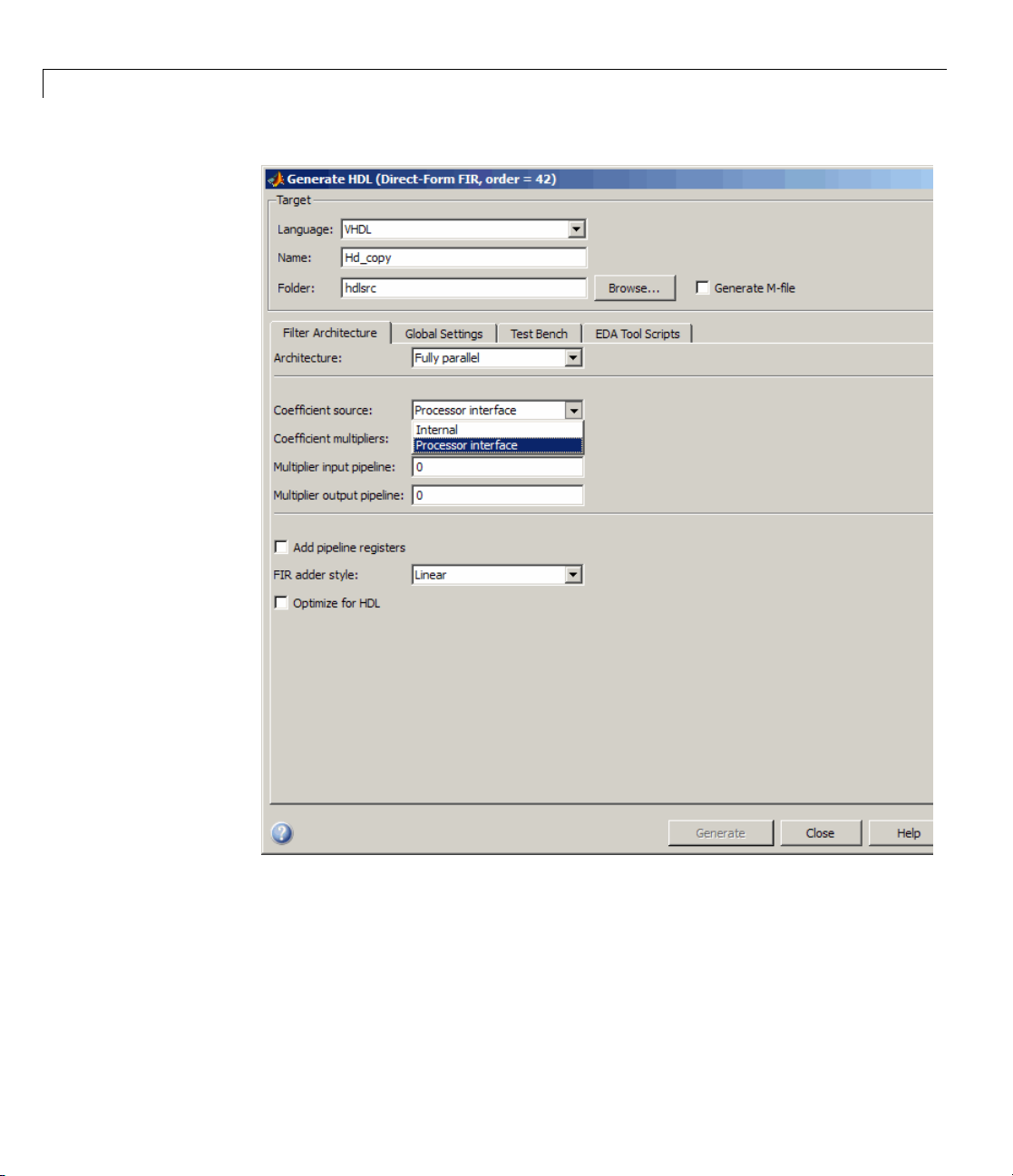
GUI Support for Processor Interface for FIR Filter
Coefficients
For direct-form FIR filters, the coder now provides two GUI options that
let you generate a processor interface for loading coefficients, and test
the interface. These options correspond to the
TestbenchCoeffStimulus properties, introduced in the previous release.
The new GUI options are:
CoefficientSource and
Page 35
Version 2.2 (R2008a) Filter Design HDL Coder™ Software
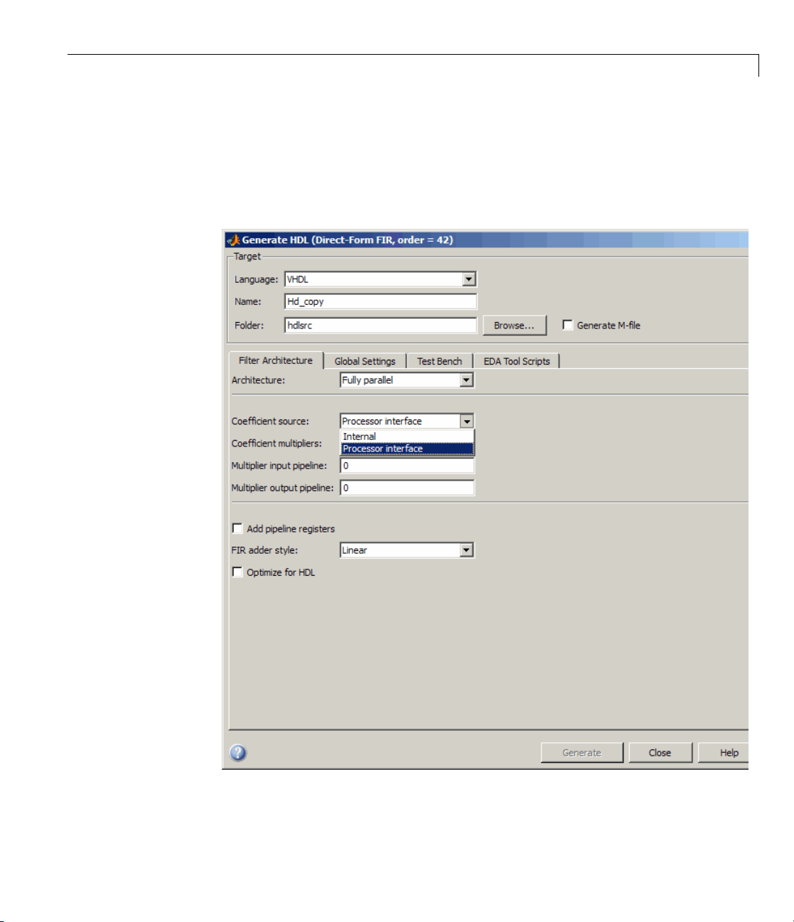
• The Coefficient source menu on the Generate HDL dialog box (shown in
the follo wing figure) lets you select whether coefficients are obtained from
the filter object and hard-coded (
(
Processor interface). The corresponding command-line property is
CoefficientSource.
Internal), or from a generated interface
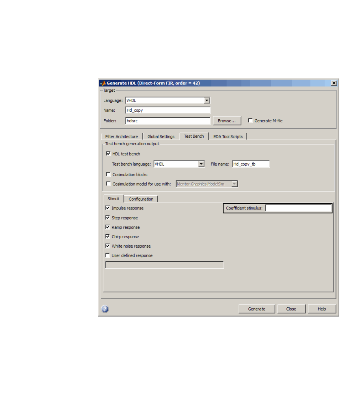
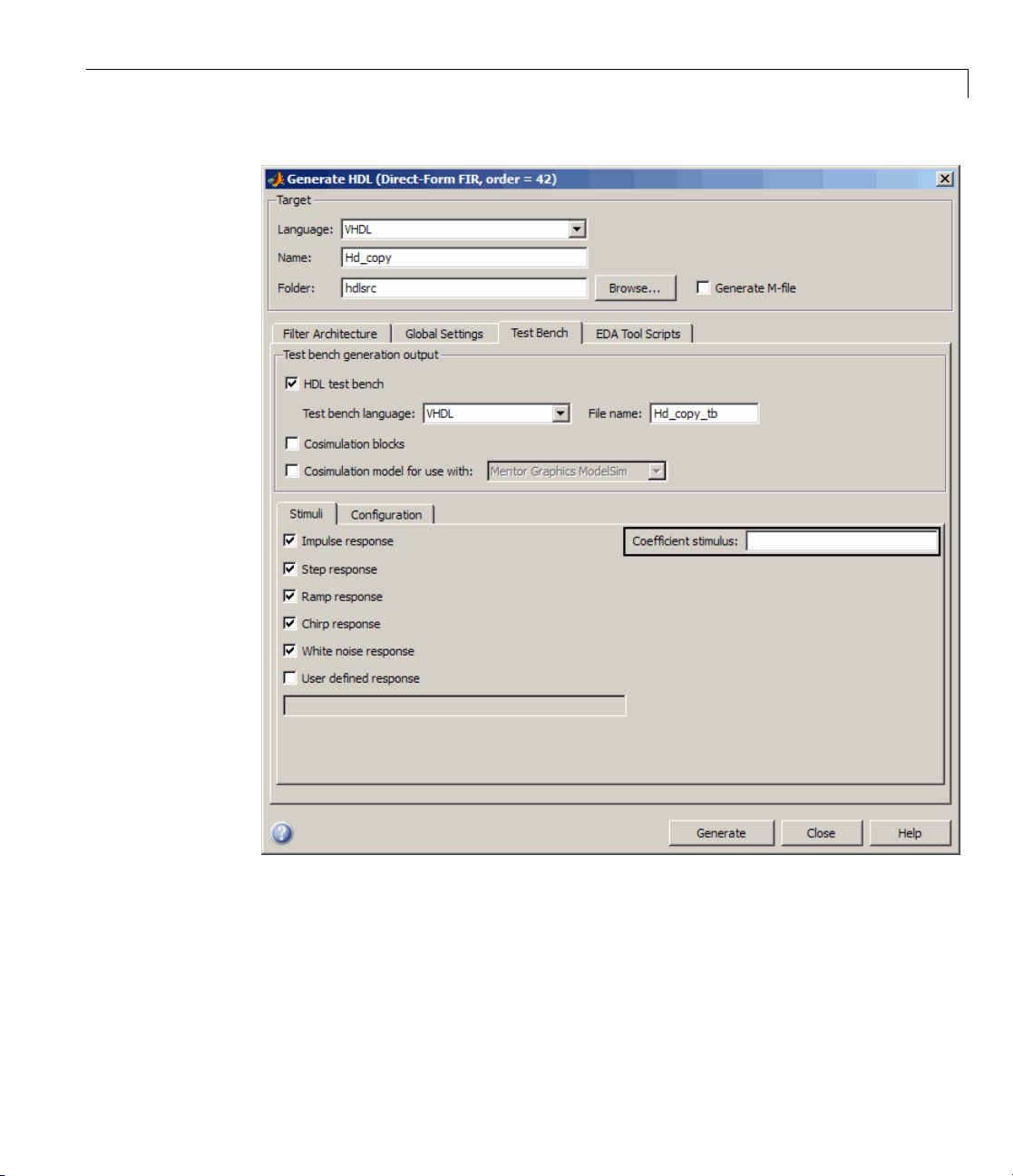
• The Coefficient stimulus option on the More Test Bench Settings
dialog box lets you specify how the test bench tests the generated
31
Page 36
Filter Design HDL Coder™ Release Notes
processor interface . The corresponding command-line property is
TestbenchCoeffStimulus.
32
For detailed information on these options, see “Specifying Programmable
Filter Coefficients for FIR Filters” in the Filter Design HDL Coder User’s
Guide.
Page 37

Version 2.2 (R2008a) Filter Design HDL Coder™ Software
generatetb Supports Default Specification of Test
Bench Type
In previous releases, the generatetb function required an explicit argument
specifying the test bench type.
In the current release, you can optionally omit the test bench type argument.
In this case, the test bench type defaults to the current setting of the
TargetLanguage property ('VHDL' or 'Verilog'). The TargetLanguage
property is set by the most recent execution of the generat ehdl command.
In the following example,
TargetLanguage is set to 'Verilog' by the
generatehdl command. Then, generatetb generates a Verilog test bench, by
default.
>> generatehdl(my_filter,'TargetLanguage','Verilog')
### Starting Verilog code generation process for filter: my_filter
### Starting Verilog code generation process for filter: my_filter
### Generating: H:\hdlsrc\my_filter.v
### Starting generation of my_filter Verilog module
### Starting generation of my_filter Verilog module body
### HDL latency is 2 samples
### Successful completion of Verilog code generation process for filter: my _filter
>> generatetb(my_filter, 'TestBenchName', 'MyFilterTB_V')
### Starting generation of VERILOG Test Bench
### Generating input stimulus
### Done generating input stimulus; length 3312 samples.
### Generating Test bench: H:\hdlsrc\MyFilterTB_V.v
### Please wait .......
### Done generating VERILOG Test Bench
See also gener atetb.
Functions and Properties Being Removed
For more information about the process of removing functions and properties,
see “About Functions and Properties Being Removed” in “What Is in the
Release Notes” on page 2.
33
Page 38
Filter Design HDL Coder™ Release Notes
Function or Property Name
'Modelsim' test bench type
argument for
generatetb
function
ScaleWarnBits property
ModelSim .do Test B ench Option Deprecated
The Modelsim .do file test bench generation option, and the
corresponding
function, are deprecated in the current release and will not be supported in
future releases.
What
Happens
Use This Instead Compatibility
Considerations
When
You Us e
Function
or
Property?
Warns
No replacement
See “ModelSim .do
Test Bench Option
Deprecated” on
page 34.
Property is
ignored
No replacement
See
“ScaleWarnBits
Property No
Longer Supported”
on page 35.
'Modelsim' test bench type argument for the generatetb
34
In the current release, the coder displays a warning during test bench
generation if this option is specified.
Compatibility Considerations
If your scripts use the 'Modelsim' test bench type argument for the
generatetb function, you should remove the 'Modelsim' argument. The test
bench type will then take a default value as described in “generatetb Supports
Default Specification of Test Bench Type” on page 33.
See also
generatetb.
Page 39

Version 2.2 (R2008a) Filter Design HDL Coder™ Software
ScaleWarnBits P
The ScaleWarnBi
option, Minimum
the Advanced pa
roperty No Longer Supported
ts
property is no longe r supported. The corresponding GUI
overlap of scale values (bits) , has been removed from
ne of the More HDL Settings dialog box.
Compatibility Considerations
If you have fil
property, su
from your cod
Summary of G
This sectio
the Filter
es that contain commands that reference the
ch reference s are ignored. Remove references to
e.
UI Enhancements and Revisions
n summarizes revisions and enhancements that have been made to
Design HDL Coder G UI.
Generate HDL Dialog Box
The Gener
See “GUI S
page 30.
ate HDL dialog box now includes the Coefficient source menu.
upport for Processor Interface for FIR Filter C oefficie nts” on
ScaleWarnBits
ScaleWarnBits
35
Page 40
Filter Design HDL Coder™ Release Notes
36
More Test Bench Settings Dialog Box
The More Test B ench Settings dialog box now includes the Coefficient
stimulus option. See “GUI Support for Processor Interface for FIR Filter
Coefficients” on page 30.
Page 41
Version 2.2 (R2008a) Filter Design HDL Coder™ Software
More HDL Settings Dialog Box
The Minimum overlap of scale values (bits) option has been removed
from the Advanced pane of the More HDL Settings dialog box. (See
“ScaleWarnBits Property No Longer Su pported” on page 35.) The following
figure shows the default settings for the Advanced pane.
37
Page 42

Filter Design HDL Coder™ Release Notes
38
Page 43
Version 2.1 (R2007b) Filter Design HDL Coder™ Software
Version 2.1 (R2007b) Filter Design HDL Coder Software
This table summarizes what’s new in Version 2.1 (R2007b).
New Features and
Changes
Yes
Details below
Version
Compatibility
Considerations
Yes—Details labeled
as Compatibility
Considerations,
below. See also
Summary.
New features and changes introduced in this version are:
• “Processor Interface for Loading FIR Filter Coefficients” on page 39
• “Generate M-file Option Captures GUI Settings to Generated Command
File” on page 40
• “Fixed-Point Round Mode Supported for H D L Code Generation” on page 42
• “New Code Generation Properties Supported” on page 42
• “Default Hardware Target for Synthesis Scripts Updated to Virtex-4” on
page 43
• “Summary of GUI Enhancements and Revisions” on page 45
Fixed Bugs an d
Known Problems
No No
Related
Documentation at
Web Site
Processor Interface for Loading FIR Filter Coefficients
In previous releases, the coder obtained filter coefficients from the filter object
and directly coded them into the generated code. An HDL filter realization
generated for a particular set of coefficients could not be used with a different
set of coefficients.
For direct-form FIR filters, the coder now provides two command-line
properties that let you generate a processor interface for loading coefficients,
and test the interface. These properties are:
•
CoefficientSource: T his property specifies whether coefficients are
directly coded, or loaded via a processor interface.
39
Page 44

Filter Design HDL Coder™ Release Notes
• TestbenchCoeffStimulus: This property specifies how the test bench tests
the generated processor interface and the performance of the filter.
See “Specifying Programmable Filter Coefficients for FIR Filters” for a
detailed description of this feature.
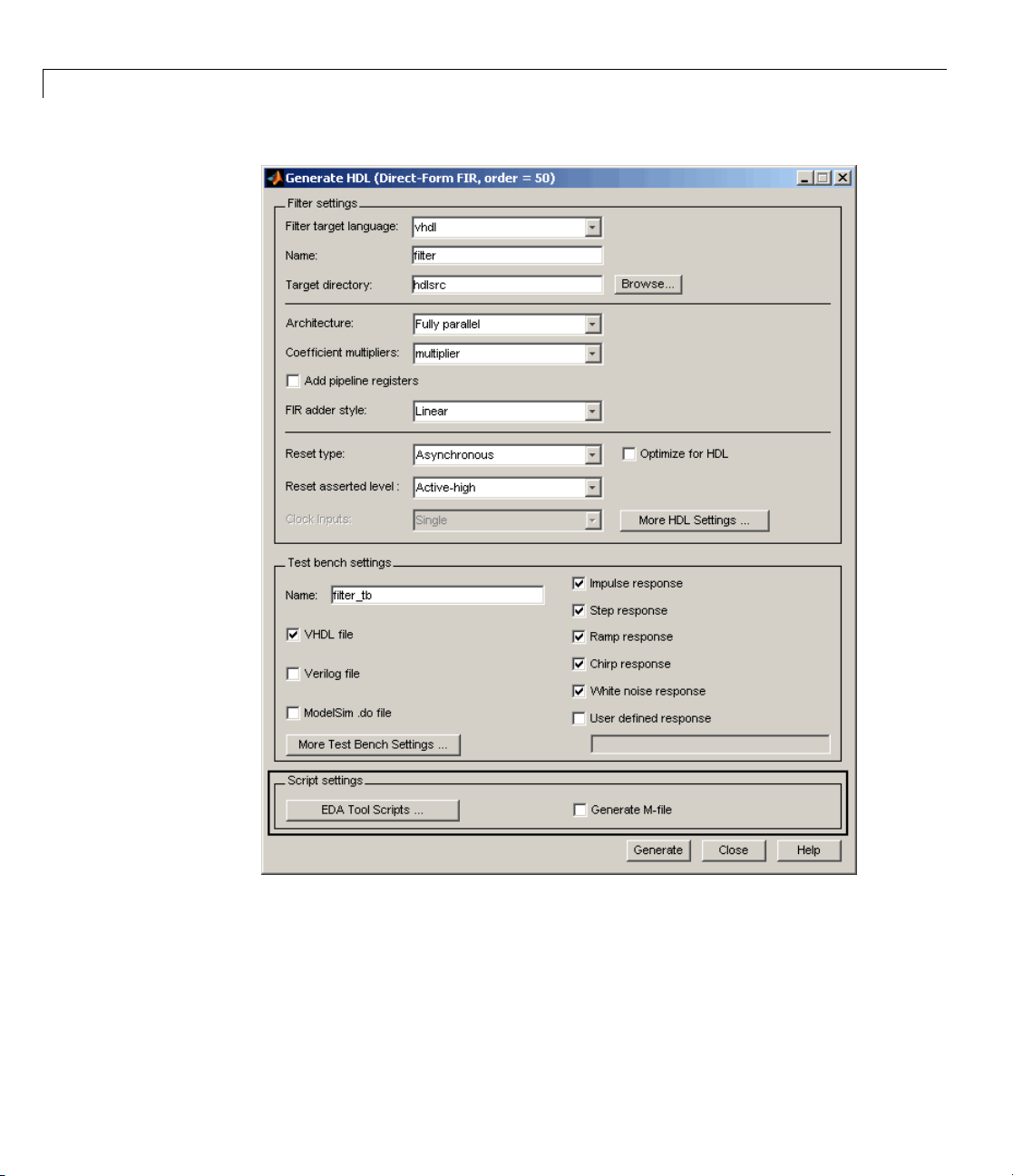
Generate M-file Option Captures GUI Settings to
Generated Command File
The new Generate M-file option of the Generate H D L dialog box makes
command-line scripting of HDL filter code and test bench generation easier.
The following figure shows the new option.
40
Page 45

Version 2.1 (R2007b) Filter Design HDL Coder™ Software
By default, Generate M-file is cleared.
When you select Generate M-file and generate code, the coder captures all
nondefault HDL code and test bench generation settings from the GUI and
writes out a MATLAB file that you can use to regenerate HDL code for the
filter.
41
Page 46

Filter Design HDL Coder™ Release Notes
For detailed information, see “Capturing Code Generation Settings to a
Script”.
Fixed-Point Round Mode Supported for HDL Code
Generation
The coder now supports t he fixed-point Round rounding mode for HDL code
generation. This rounding mode behaves identically to the MATLAB
function.
Compatibility Considerations
In previous releases, the coder did not support this roundin g behavior in
generated HDL code. When generating code from a filter that had the
RoundMode property se t to Round,thecoderusednearest rounding mode
instead. (See “Rounding Behavior in Generated HDL Code” on page 75 for a
detailed description of the rounding behavior in previous releases.)
If you have scripts or other programs that generate HDL code from filter
objects that have the
your generated HDL filters may differ from results obtained from previous
releases. You may w an t to update your scripts a ccordingly.
round
RoundMode property set to Round, the behavior of
42
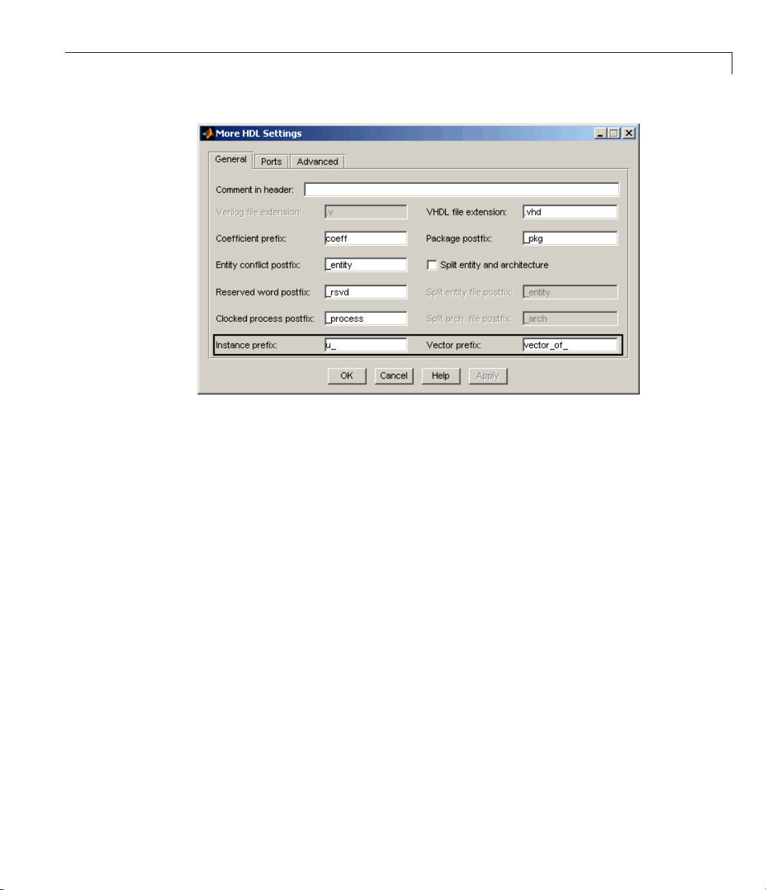
New Code Generation Properties Supported
The coder supports two new code generation properties:
•
InstancePrefix: This property specifies a string to be prefixed to
component instance names in generated code. The default string is
VectorPrefix: This property specifies a stringtobeprefixedtovector
•
names in generated VHDL code. The default string is
Note VectorPrefix is supported only for VHDL code generation
You can view and edit these new properties via the Instance prefix and
Vector prefix edit fields on the General pane of the More HDL Settings
dialog box, show n in the following figure.
vector_of_.
u_.
Page 47

See also:
Version 2.1 (R2007b) Filter Design HDL Coder™ Software
• “Setting a Prefix for Component Instance Names”
• “Setting a Prefix for Vector Names”
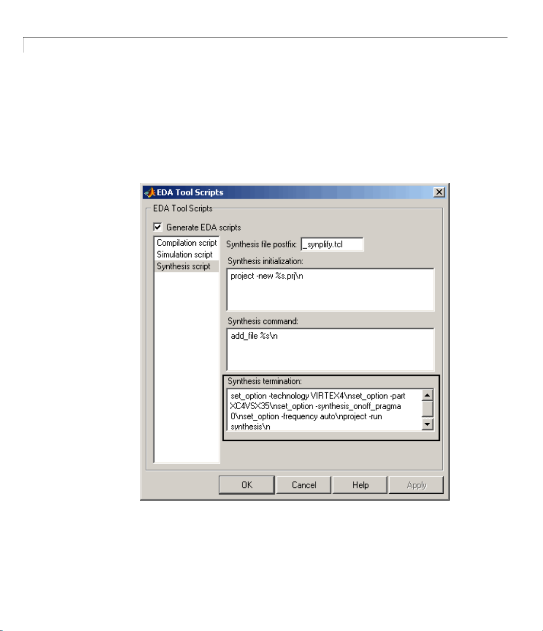
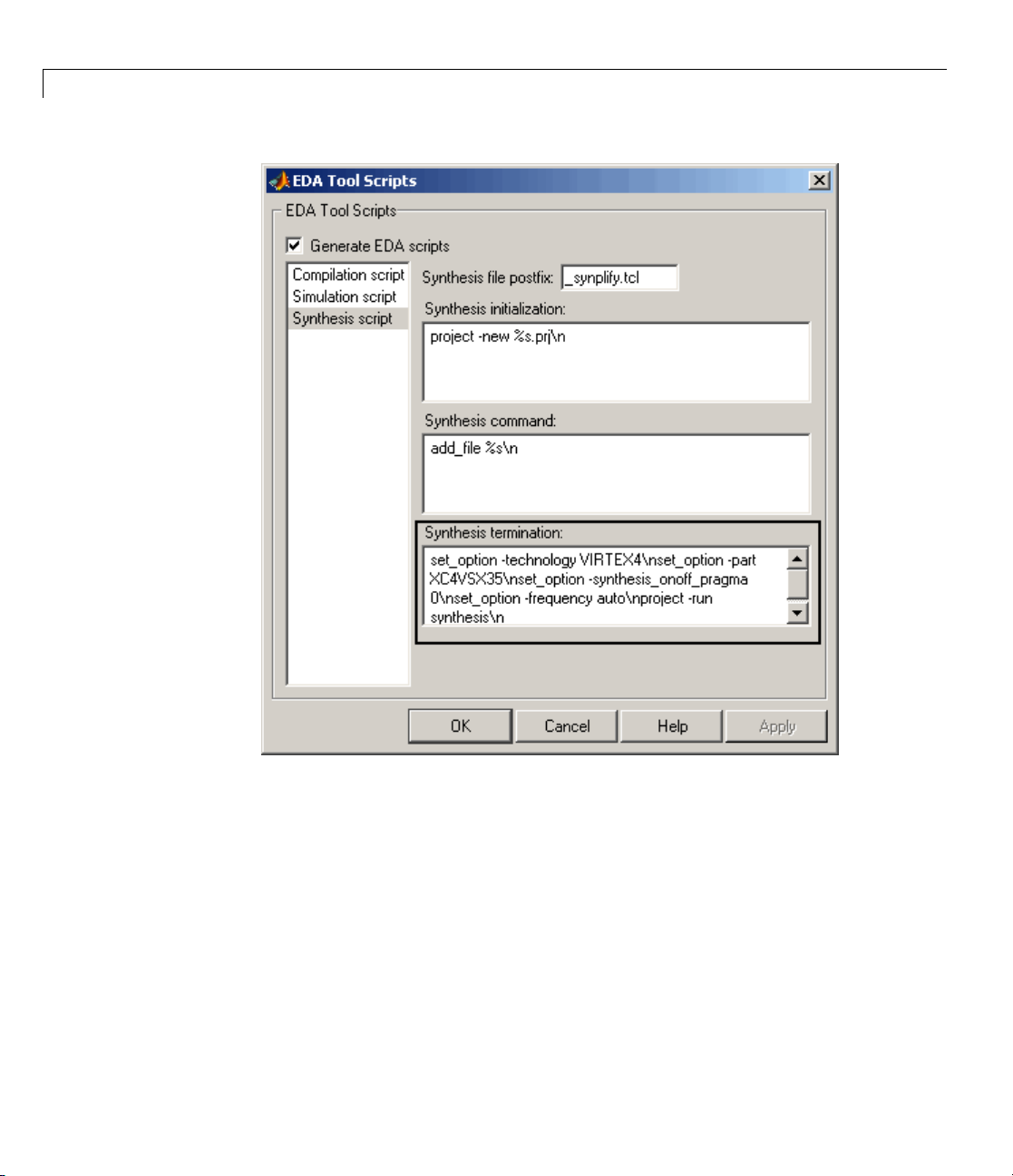
Default H ardware Target for Synthesis Scripts
Updated to V irtex-4
The default hardware target string in generated synthesis scripts now
specifies:
•
technology option: VIRTEX4
In previous releases, this option defaulted to VIRTEX2.
part option: XC4VSX35
•
In previous releases, this option defaulted to XC2V500.
Theseupdatesaffectthedefaultvalueforthe
default is:
['set_option -technology VIRTEX4\n',...
'set_option -part XC4VSX35\n',...
HDLSynthTerm property. The
43
Page 48
Filter Design HDL Coder™ Release Notes
'set_option -synthesis_onoff_pragma 0\n',...
'set_option -frequency auto\n',...
'project -run synthesis\n']
ThedefaultvaluefortheHDLSy nthT erm property appears in the Synthesis
termination field of the EDA Tool Scripts dialog box, as shown in the
following figure.
44
See also “Generating Scripts for EDA Tools”.
Page 49

Version 2.1 (R2007b) Filter Design HDL Coder™ Software
Compatibility Considerations
If you have existing code that generates synthesis scripts using the previous
defaults for
regenerate synthesis scripts.
technology or part, you may want to update your code and
Summary of GUI Enhancements and Revisions
For Version 2.1, revisions and enhancements have been made to the Filter
Design HDL Coder GUI.
Generate HDL Dialog Box
The following figure shows the Generate HDL dialog box. Revisions and
enhancements to this dialog box include:
• The new Generate M-file option. When you select this option, the code
generator captures all nondefault HDL code and test be nch generation
settings from the GUI and writes out a file that you can use to reconstruct
the filter and regenerate HDL code. See “Generate M-file Option Captures
GUI S ettings to Generated Command File” on page 40 for details.
• The EDA Tool Scripts button and the Generate M-file option are
grouped together in a new Script settings section.
45
Page 50
Filter Design HDL Coder™ Release Notes
46
More HDL Settings Dialog Box
The General pane of the More H DL Settings dialog box supports the new
Instance prefix and Vector prefix properties, as shown in the following
figure. See “New Code Generation Properties Supported” on page 42 for
details.
Page 51
Version 2.1 (R2007b) Filter Design HDL Coder™ Software
EDA Tool Scripts Dialog Box
In the EDA Tool Scripts dialog box, the default value for the Synthesis
termination field has changed (see “Default Hardware Target for Synthesis
Scripts Updated to Virtex-4” on page 43) as shown in the following figure.
47
Page 52
Filter Design HDL Coder™ Release Notes
48
Page 53

Version 2.0 (R2007a) Filter Design HDL Coder™ Software
Version 2.0 (R2007a) Filter Design HDL Coder Software
This table summarizes what’s new in Version 2.0 (R2007a).
New Features and
Changes
Yes
Details below
Version
Compatibility
Considerations
No No No
New features and changes introduced in this version are:
• “Farrow Filter Code Generation” on page 49
• “Code Generation Support for Pol yphase Sample Rate Converters
(mfilt.firsrc)” on page 50
• “filterbuilder Supports HDL Code Generation” on page 50
• “fdhdltool Function Opens Generate HD L Dialog Box from the Command
Line” on page 52
• “GUI Enhancements and Revisions” on page 52
• “EDA Tool Scripts Dialog Box” on page 57
• “Multiple Clocks Supported for Multirate Filters with Distributed
Arithmetic and Fully Serial Architectures” on page 61
Fixed Bugs an d
Known Problems
Related
Documentation at
Web Site
Farrow Filter Code Generation
The coder now supports HDL code generation for Farrow filters. The Farrow
filter structures supported are:
•
farrow.fd
• farrow.linearfd
A Farrow filter differs from a conventional filter because it has a fractional
delay input in addition to a signal input. The fractional delay input enables
the use of time-varying delays, as the filter operates. The fractional delay
input receives a signal taking on values between 0 and 1.0. For general
49
Page 54

Filter Design HDL Coder™ Release Notes
information how to construct and use Farrow filter objects, see the farrow
function refere nce section of the Filter Design Toolbo x™ documentation.
The coder provides
GUI options that let you:
• Define the fractional delay port name used in generated code.
• Apply a variety of test bench stimulus signals to the fractional delay port,
or define your own stimulus signal.
See “Generating Code for Single-Rate Farrow Filters” in the Filter Design
HDL Coder User’s Guide for a complete description of this feature.
generatetb and generatehdl properties and equivalent
Code Generation Support for Polyphase Sample Rate
Converters (mfilt.firsrc)
The coder now supports code generation for direct-form FIR polyphase sample
rate converters (
that com bin es an interp olation factor an d a decim ation factor, allowing you to
perform fractional interpolation or decimation on an input signal.
For detailed information on this feature, see “Generating Code for Polyphase
Sample Rate Converters” in the Filter Design HDL Coder User’s Guide.
mfilt.firsrc). mfi lt.firsrc is a multirate filter structure
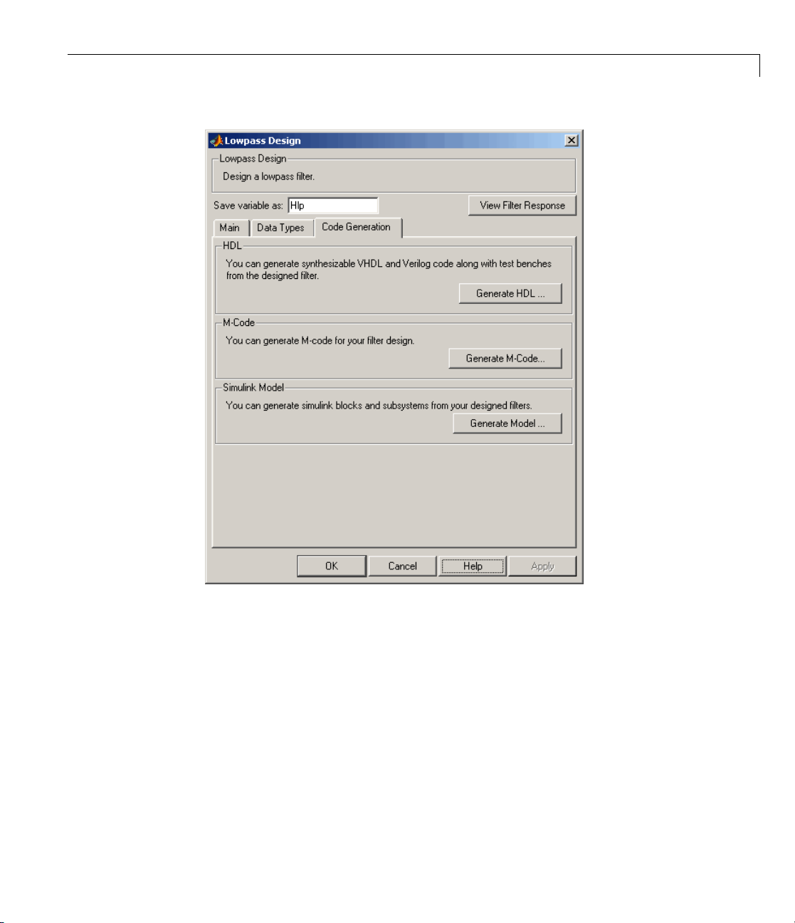
filterbuilder Supports HDL Code Generation
You can now use the filterbuilder tool to generate HDL code for any filter
object designed in
Code Generation pane (shown in the following figure).
filterbuilder.Thefilterbuilde r GUI now includes a
50
Page 55
Version 2.0 (R2007a) Filter Design HDL Coder™ Software
To generate HDL code from filterbuilder:
1 Click the Code Generation tab.
2 In the Code Generation pane, click the Generate HDL button. This
opens the Generate HDL dialog box, passing in the current filter object
from
filterbuilder.
3 Set the desired code generation and test bench options and generate code in
the Generate H D L dialog box.
51
Page 56

Filter Design HDL Coder™ Release Notes
Seealso“GUIEnhancementsandRevisions”onpage52tolearnabout
changesthathavebeenmadetotheGenerateHDLdialogboxandits
subordinate dialog boxes.
fdhdltool Function Opens Generate HDL Dialog Box
from the Command Line
fdhdltool is a convenience function that lets you o pe n the Generate HDL
dialog box from the command line.
The command syntax is
fdhdltool(Hd)
where Hd is a filter object.
The
fdhdltool function is particularly useful when you need to use the Filter
Design HDL Coder GUI to generate HDL code for filter structures that are
not supported by FDATool or
commands create a Farrow linear fractional delay filter object
passed in to the
filterbuilder. For example, the following
Hd,whichis
fdhdltool function.
52
D=.3;
Hd = farrow.linearfd(D);
Hd.arithmetic = 'fixed';
fdhdltool(Hd);
fdhdltool
operates on a copy of the filter object, rather than the original
object in the workspace. Any changes made to the original filter object after
fdhdltool is invoked will not affect the copy and will not update the Generate
HDL dialog box.
The naming convention for the copied object is filt
_copy,wherefilt is the
name of the original filter object.
GUI Enhancements and Revisions
For Release 2.0, significant revisions and enhancements have been made to
the Filter Design HDL C o der GUI.
Page 57

Generate HDL Dialog Box
Version 2.0 (R2007a) Filter Design HDL Coder™ Software
The preceding figure shows the Generate HDL dialog box. Revisions and
enhancements to this dialog box include:
• The new EDA Tool Scripts button opens the EDA Tool Scripts dialog
box, which lets you set properties that control generation of script files
53
Page 58
Filter Design HDL Coder™ Release Notes
for third-party electronic design automation (EDA) tools. See “EDA Tool
Scripts Dialog Box” on page 57.
• The More HDL Settings button opens the More HDL Settings dialog box,
which replaces the HDL Options dialog box.
• The More Test Bench Settings button opens the More Test Bench
Settings dialog box, which replaces the Test Bench Options dialog box.
More HDL Settings Dialog Box
TheMoreHDLSettingsdialogboxdiffers slightly from the HDL Settings
dialog box, which it replaces.
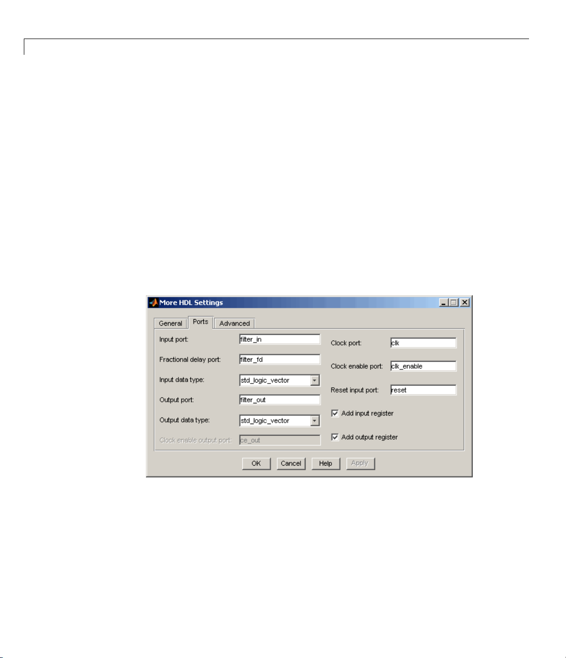
In the Ports pane, when the current filter object is a Farrow filter (see
“Farrow Filter Co de Generation” on page 49), the new Fractional delay
port field is displayed, as shown in the following figure.
54
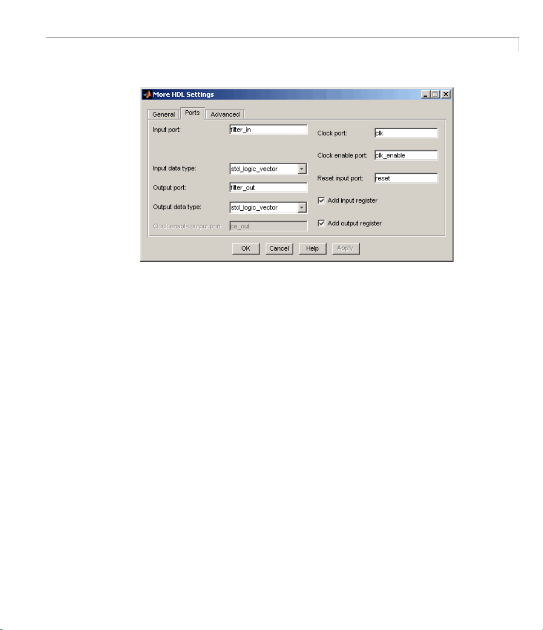
Forallotherfiltertypes,theFractional delay port field is omitted, as
shown in the following figure.
Page 59
Version 2.0 (R2007a) Filter Design HDL Coder™ Software
More Test B
The M o re Test Bench Settings dialog box differs slightly from the Test Bench
Settings dialog box, which it replaces.
When the current filter object is a Farrow filter (see “Farrow Filter Code
Generation” on page 49), the new Fractional delay stimulus and User
defined stimulus options are displayed, as shown in the following figure.
ench Settings Dialog Box
55
Page 60

Filter Design HDL Coder™ Release Notes
56
Forallotherfiltertypes,theFractional delay stimulus and User defined
stimulus options are omitted, as shown in the following figure.
Page 61

Version 2.0 (R2007a) Filter Design HDL Coder™ Software
EDA Tool Scripts Dialog Box
The new EDA Tool Scripts dialog box lets you set all options that control
generation of script files for third-party electronic design automation (EDA)
tools. In previous releases, script generation options were available only
through
To open the EDA Tool Scripts dialog box, click on the EDA Tool Scripts
button in the Generate HDL dialog box (shown in the following figure).
generatehdl properties.
57
Page 62
Filter Design HDL Coder™ Release Notes
58
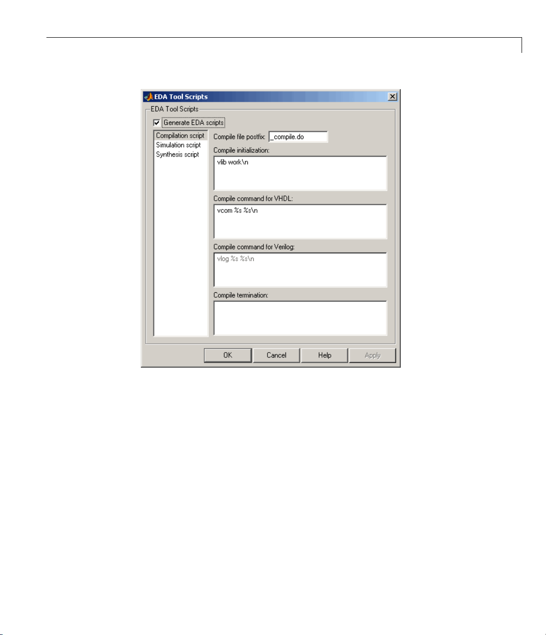
The following figures show the three panes of the EDA Tool Scripts dialog box.
The Compilation script pane displays options related to customizing scripts
for compilation of generated VHDL or Verilog code.
Page 63
Version 2.0 (R2007a) Filter Design HDL Coder™ Software
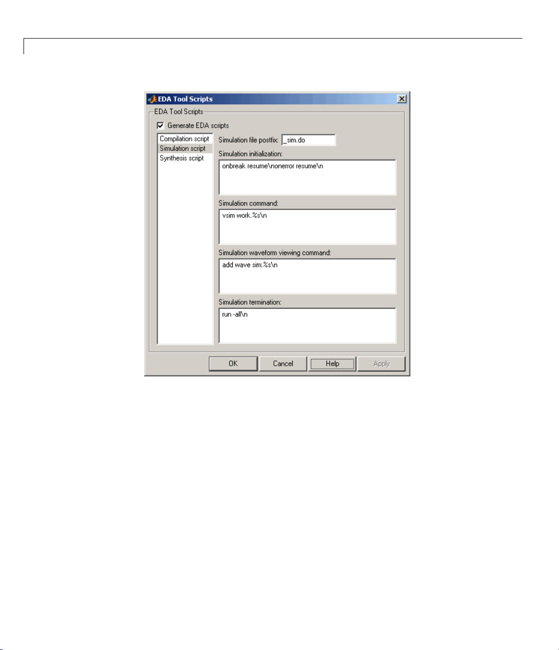
The Simulation script pane displays options related to customizing scripts
for HDL simulators.
59
Page 64
Filter Design HDL Coder™ Release Notes
60
The Synthesis script pane displays options related to customizing scripts for
synthesis tools.
Page 65

Version 2.0 (R2007a) Filter Design HDL Coder™ Software
See “Generating Scripts for EDA Tools” for a detailed description of script
generation options.
Multiple Clocks Supported for Multirate Filters with
Distributed Arithmetic and Fully Serial Architectures
In previous releases, for multirate filters with a distributed arithmetic (DA)
or fully serial architecture specified, the Clock inputs options was set to
Single and disabled.
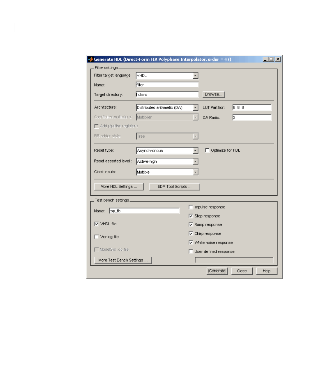
The coder now supports specification of either single or multiple clock inputs
for multirate filters with a DA or full y serial architecture.
For example, in the following figure, the Clock inputs option was set to
Multiple for a direct-form FIR polyphase interpolator (mfilt.firinterp).
with a DA architecture.
61
Page 66
Filter Design HDL Coder™ Release Notes
62
Note For multirate filters with the Partly serial architecture option
selected, the Clock inputs optionsissetto
Single and disabled.
See also:
Page 67

Version 2.0 (R2007a) Filter Design HDL Coder™ Software
• “Distributed Arithmetic for FIR Filters” in the Filter Design HDL Coder
User’s Guide for a complete description of DA related options and
properties.
• “Speed vs. Area Optimizations for FIR Filters” in the Filter Design HDL
Coder User’s Guide for a complete description of serial architectures.
63
Page 68
Filter Design HDL Coder™ Release Notes
Version 1.5 (R2006b) Filter Design HDL Coder Software
This table summarizes what’s new in Version 1.5 (R2006b).
New Features and
Changes
Yes
Details below
Version
Compatibility
Considerations
Yes—Details labeled
as Compatibility
Considerations,
below. See also
Summary.
New features and changes introduced in this version are
• “Distributed Arithmetic Support f o r FIR Filters” on page 64
• “Multirate Support for Fully Serial Architectures” on page 66
• “Generate HDL Dialog Box Supports All Parallel and Serial Architecture
Options” on page 67
• “Enhanced Code Generation for Symmetric Multirate FIR Filters” on page
70
• “EDAScriptGeneration Property Added” on page 70
• “ResetValue Property Merged with ResetAssertedLevel Property” on page
70
• “Clock EnableValue for Test Benches Always Active-High” on page 71
Fixed Bugs an d
Known Problems
Bug Reports No
Related
Documentation at
Web Site
64
Distributed Arithmetic Support for FIR Filters
The coder now supports Distributed Arithmetic (DA) in HDL code generated
for several single-rate and multirate FIR filter structures. DA i s a
widely-used technique for implementing sum of products computations
without use of multipliers. Designers frequently use DA to build efficient
Multiply-Accumulate Circuitry (MAC ) for filters and o the r DSP a pplications.
DA code generation is supported for fixed-point realizations of the following
FIR filter structures:
Page 69

Version 1.5 (R2006b) Filter Design HDL Coder™ Software
• dfilt.dffir
• dfilt.dfsymfir
• dfilt.dfasymfir
• mfilt.firdecim
• mfilt.firinterp
You can enable and control DA code generation using generatehdl properties
provided for that purpose, or by selecting the
Distributed Arithmetic (DA)
option from the Architecture pop-up menu in the Generate HDL dialog
box (shown in the following figure).
See “Distributed Arithmetic for FIR Filters” in the Filter Design HDL Coder
documentation for a complete description of DA related options and properties.
65
Page 70
Filter Design HDL Coder™ Release Notes
66
Multirate Support for Fully Serial Architectures
The coder adds support for generation of fully serial architectures for the
following multirate filter types:
•
mfilt.firdecim
• mfilt.firinterp
Page 71

Version 1.5 (R2006b) Filter Design HDL Coder™ Software
The following table summarizes the filter types that are available for parallel
and serial architecture choices. See “Speed vs. Area Optimizations for FIR
Filters”intheFilterDesignHDLCoderUser’sGuideforafulldescription
of these options.
Architecture
Fully parallel (default) All filter types that are supported for
Fully serial • dfilt.dffir
Partly serial • dfilt.dffir
Cascade serial • dfilt.dffir
Available for Filter Types...
HDL code generation
• dfilt.dfsymfir
• dfilt.dfasymfir
• mfilt.firdecim
• mfilt.firinterp
• dfilt.dfsymfir
• dfilt.dfasymfir
• dfilt.dfsymfir
• dfilt.dfasymfir
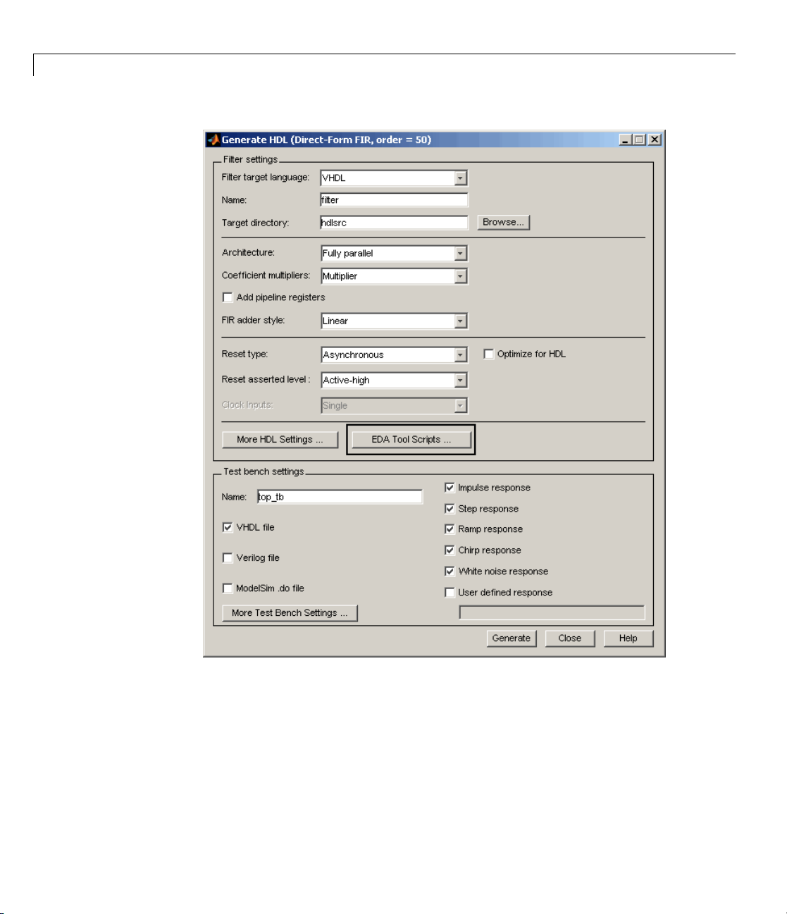
Generate HDL Dialog Box Supports All Parallel and
Serial Architecture Options
Previously, the Architecture po p-u p menu on the HDL Options dialog box
provided a choice between two basic (
architectures. O ther architecture options were available only by setting
generatehdl properties (ReuseAccum and SerialPartiti on).
Fully parallel or Fully serial)
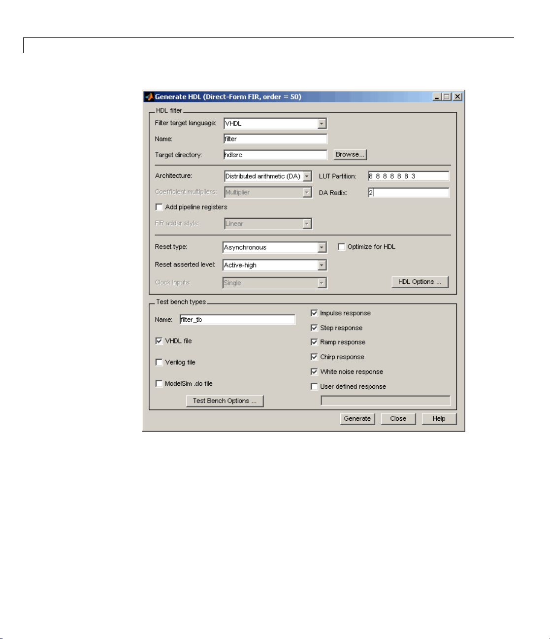
The Generate HDL dialog box now supports the full range of architecture
options. As shown in the following figure, the Architecture pop-up menu
now includes
Partly serial and Cascade serial options.
67
Page 72

Filter Design HDL Coder™ Release Notes
68
When the Partl y serial or Cascade serial option is selected, the Generate
HDL dialog box displays the Serial Partition field (shown in the following
figure). See “Speed vs. Area Optimizations for FIR Filters” in the Filter
Design HDL Coder User’s Guide for a full description of serial and parallel
architecture options.
Page 73

Version 1.5 (R2006b) Filter Design HDL Coder™ Software
Note The Architecture pop-up menu also includes the new Distributed
arithmetic (DA)
option (see “Distributed Arithmetic Support for FIR
Filters” on page 64).
69
Page 74

Filter Design HDL Coder™ Release Notes
Enhanced Code Generation for Symmetric Multirate
FIR Filters
In this release, the coder enhances code generation for Direct-Form FIR
Polyphase Decimator (
polyphase coefficients for each FIR subfilter. The code generator inserts
adders before multipliers to sum the input samples that correspond to the
symmetric taps.
EDAScriptGeneration Property Added
The EDAScriptGeneration property controls the generation of script files. By
default,
EDAScriptGeneration to 'off', as in the following example:
See “Generating Scripts for EDA Tools” in the Filter Design HDL Coder
User’s Guide for further information.
EDAScriptGeneration is set 'on'. To disable script generation, set
generatehdl(Hd,'EDAScriptGeneration','off')
mfilt.firdecim) filters by using the symmetry in
70
ResetValue Property Merged with ResetAssertedLevel
Property
In previous releases, the ResetValue property (or the Reset value option in
the Test Bench Options dialog box) allowed test bench reset input signal
levels (
specified for resets in the generated f ilter code.
In this release, the
ResetAssertedLevel property (Re set asserted level menu in the HDL
filter pane of the Generate HDL dialog box). The Reset asserted level
setting determines the rest level for both filter and test bench reset input
signals, ensuring consistency among reset signals.
Compatibility Considerations
If you have existing scripts or saved FDATool settings that rely on setting the
ResetValue property independently of ResetAssertedLevel,youshould
change them to use only
active-high or active-lo w)tobesetindependentlyfromthelevel
ResetValue property has been merged with the
ResetAssertedLevel.
Page 75

Version 1.5 (R2006b) Filter Design HDL Coder™ Software
Clock EnableValue for Test Benches Always
Active-High
The clock enable value for test benches is now always active-high. The
ClockEnableValue property and the corresponding Clock enable value
option in the Test Bench Options dialog box have been removed. Setting an
active-low clock enable value for test benches is no longer supported.
Compatibility Considerations
You should remove any code that sets or references the ClockEnableValue
property from your existing scripts.
71
Page 76

Filter Design HDL Coder™ Release Notes
Version 1.4 (R2006a) Filter Design HDL Coder Software
This table summarizes what’s new in V1.4 (R2006a):
New Features and
Changes
Yes
Details below
Version
Compatibility
Considerations
Yes—Details labeled
as Compatibility
Considerations,
below. See also
Summary.
New features and changes introduced in this version are
• “Speed vs. Area Tradeoff Options for FIR Filters” on page 72
• “Code Generation Support for Delay Filter” on page 74
• “Rounding Behavior in Generated HDL Code” on page 75
Fixed Bugs an d
Known Problems
Bug Reports
at Web site
Related
Documentation at
Web Site
No
Speed vs. Area Tradeoff Options for FIR Filters
The coder now provides options that extend your control over speed vs. area
tradeoffs in the realization of single-rate direct-form FIR filter designs.
This release note summarizes the new options. See “Speed vs. Area
Optimizations for FIR Filters” in the Filter Design HD L Coder User’s Guide
for full details and examples. Further examples are given in the HDL Serial
Architectures for FIR Filters demo (
hdlserialfir.m).
72
To achieve the desired speed vs. area tradeoff, you can either specify a fully
parallel architecture for generated HDL filter code, or choose one of several
serial architectures. The following architectures are supported:
• Fully parallel: This is the default option. A fully parallel architecture
uses a dedicated multiplier and a dder for each filter tap; all taps execute
in parallel. A fully parallel architecture is optimal for speed. However,
it requires more multipliers and adders than a serial architecture, and
therefore consumes more chip area.
Page 77

Version 1.4 (R2006a) Filter Design HDL Coder™ Software
• Fully serial: A fully serial architecture conserves area by reusing multiplier
and adder resources sequentially. For example, a four-tap filter design
would use a single multiplier and adder, executing a multiply/accumulate
once for each tap. The multiply/accumulate section of the design runs at
four times the filter’s input/output sample rate. This saves area at the cost
of some speed loss and higher p ower consumption.
• P artly serial: Partly serial architectures cover the full r ang e of speed vs.
area tradeoffs that lie between the two extreme cases, fully parallel and
fully serial architectures.
In a partly serial architecture, the filter taps are grouped into a number of
serial partitions. The taps within each partition execute serially, but the
partitions execute in parallel with respect to one another. The outputs of
the partitions are summed at the final output.
• C ascade-serial: A cascade-serial architecture closely resembles a partly
serial architecture. As in a partly serial architecture, the filter taps are
grouped into a number of serial partitions that execute in parallel with
respect to one another. However, the accumulated output of each partition
is cascaded to the accumulator of the previous partition. The output of all
partitions is therefore computed at the accumulator of the first partition.
This technique is termed accumulator reuse. No final adder is required,
which saves area.
The full range of parallel/serial architecture options is supported by new
properties passed in to the
generatehdl command.
Alternatively, you can use the new Architecture option on the HDL O p tions
dialog box (see the following figure) to choose between the basic
Parallel
or Fully Serial architectures.
Fully
73
Page 78

Filter Design HDL Coder™ Release Notes
74
The new options are supported for the following filter types:
•
dfilt.dffir
• dfilt.dfsymfir
• dfilt.dfasymfir
Code Generation Support for Delay Filter
The coder now supports code generation for the Delay filter type
(
dfilt.delay). See the Signal Processing Toolbox™ documentation for
information on this filter type.
Page 79

Version 1.4 (R2006a) Filter Design HDL Coder™ Software
TheDelayfilterisoftenusedinacascadewithotherfiltertypes. See
“Generating Code for Cascade Filters” Filter D esign HDL Coder User’s Guide
for gene ral considerations on using cascade filters in code generation.
Rounding Behavior in Generated HDL Code
In Release 2006a, filter objects (and fixed-point arithmetic in general) support
a fixed-point rounding mode (
round function. However, the coder does n ot support this rounding behavior
in generated HDL code. When generating code from a filter that has the
RoundMode property set to Round,ThecoderusesNearest rounding mode
instead. A warning is issued when code generation is initiated, as shown in
the following example.
b = [0.05 0.9 0.05];
Hd = dfilt.dffir(b);
Hd.arithmetic = 'fixed';
Hd.FilterInternals = 'SpecifyPrecision';
Hd.RoundMode = 'Round';
generatehdl(Hd);
Warning: RoundMode 'round' is not supported for HDL generation. Using 'near est' instead.
.
.
.
### Successful completion of VHDL code generation process for filter: Hd
Round) that behaves identically to the MATLAB
If you are generating code from a fixed-point filter created in FDATool, th is
situation does not occur because the FDATool Round towards menu does
not include the
Round option.
Compatibility Considerations
Before generating HDL code from your existing filter objects, check the
RoundMode property and if it is set to Round, use another mode to avoid the
warning.
75
Page 80
Filter Design HDL Coder™ Release Notes
Compatibility Summary for Filter Design HDL Coder
Software
This table summarizes new features and changes that might cause
incompatibilities when you upgrade from an earlier version, or wh en you
use files on multiple versions. Details are provided in the description of the
new feature or change.
Version (Release) New Features and Changes with
Version Compatib ility Impact
Latest Version
V2.6 (R2010a)
V2.5 (R2009b) See the Compatibility
V2.4 (R2009a) See the Compatibility
See the Compatibil ity
Considerations subheading
for this new feature or change:
• “GenerateCosimModel ’IN’ and
’MQ’ Property Values Removed”
on page 12
Considerations subheading
for this new feature or change:
• “Graphical User Interface
Improved and Revised” on page 13
• “GenerateCosimModel ’IN’ and
’MQ’ Property Values Replaced”
on page 17
Considerations subheading
for this new feature or change:
• “Default Entity Conflict Postfix
Changed” on page 24
76
Page 81
Compatibility Summary for Filter Design HDL Coder™ Software
Version (Release) New Features and Changes with
Version Compatib ility Impact
V2.3 (R2008b) See the Compatibility
Considerations subheading
for this new feature or change:
• “-novopt Flag Added to the
Default Simulation Command in
Generated Compilation Scripts”
on page 28
• “ModelSim .do Test Bench Option
Removed” on page 28
V2.2 (R2008a) See the Compatibility
Considerations subheading
for this new feature or change:
• “ScaleWarnBits Property No
Longer Supported” on page 35
• “ModelSim .do Test Bench Option
Deprecated” on page 34
V2.1 (R2007b) See the Compatibility
Considerations subheading
for this new feature or change:
• “Fixed-Point Round Mode
Supported for HDL Code
Generation” on page 42
• “Default Hardware Target for
Synthesis Scripts Updated to
Virtex-4” on page 43
V2.0 (R2007a)
None
77
Page 82

Filter Design HDL Coder™ Release Notes
Version (Release) New Features and Changes with
V1.5 (R2006b) See the Compatibility
V1.4 (R2006a) See the Compatibility
Version Compatib ility Impact
Considerations subheading
for this new feature or change:
• “ResetValue Property Merged
with ResetAssertedLevel
Property” on page 70
• “Clock EnableValue for Test
Benches Always Active-High” on
page 71
Considerations subheading
for this new feature or change:
• “Rounding Behavior in Generated
HDL Code” on page 75
78
 Loading...