

Page 1

EDA Simulator Link
User’s Guide
™3
Page 2

How to Contact The MathWorks
www.mathworks.
comp.soft-sys.matlab Newsgroup
www.mathworks.com/contact_TS.html T echnical Support
suggest@mathworks.com Product enhancement suggestions
bugs@mathwo
doc@mathworks.com Documentation error reports
service@mathworks.com Order status, license renewals, passcodes
info@mathwo
com
rks.com
rks.com
Web
Bug reports
Sales, prici
ng, and general information
508-647-7000 (Phone)
508-647-7001 (Fax)
The MathWorks, Inc.
3 Apple Hill Drive
Natick, MA 01760-2098
For contact information about worldwide offices, see the MathWorks Web site.
EDA S imulator Link™ User’s Guide
© COPYRIGHT 2003–2010 by The MathWorks, Inc.
The software described in this document is furnished under a license agreement. The software may be used
or copied only under the terms of the license agreement. No part of this manual may be photocopied or
reproduced in any form without prior written consent from The MathW orks, Inc.
FEDERAL ACQUISITION: This provision applies to all acquisitions of the Program and Documentation
by, for, or through the federal government of the United States. By accept ing delivery of the Program
or Documentation, the government hereby agrees that this software or documentation qualifies as
commercial computer software or commercial computer software documentation as such terms are used
or defined in FAR 12.212, DFARS Part 227.72, and DFARS 252.227-7014. Accordingly, the terms and
conditions of this Agreement and only those rights specified in this Agreement, shall pertain to and govern
theuse,modification,reproduction,release,performance,display,anddisclosureoftheProgramand
Documentation by the federal government (or other entity acquiring for or through the federal government)
and shall supersede any conflicting contractual terms or conditions. If this License fails to meet the
government’s needs or is inconsistent in any respect with federal procurement law, the government agrees
to return the Program and Docu mentation, unused, to The MathWorks, Inc.
Trademarks
MATLAB and Simulink are registered trademarks of The MathWorks, Inc. See
www.mathworks.com/trademarks for a list of additional trademarks. Other product or brand
names may be trademarks or registered trademarks of their respective holders.
Patents
The MathWorks products are protected by one or more U.S. patents. Please see
www.mathworks.com/patents for more information.
Page 3

Revision History
August 2003 Online only New for Version 1 (Release 13SP1)
February 2004 Online only Updated for Version 1.1 (Release 13SP1)
June 2004 Online only Updated for Version 1.1.1 (Release 14)
October 2004 Online only Updated for Version 1.2 (Release 14SP1)
December 2004 Online only Updated for Version 1.3 (Release 14SP1+)
March 2005 Online only Updated for Version 1.3.1 (Release 14SP2)
September 2005 Online only Updated for Version 1.4 (Release 14SP3)
March 2006 Online only Updated for Version 2.0 (Release 2006a)
September 2006 Online only Updated for Version 2.1 (Release 2006b)
March 2007 Online only Updated for Version 2.2 (Release 2007a)
September 2007 Online only Updated for Version 2.3 (Release 2007b)
March 2008 Online only Updated for Version 2.4 (Release 2008a)
October 2008 Online only Updated for Version 2.5 (Release 2008b)
March 2009 Online only Updated for Version 2.6 (Release 2009a)
September 2009 Online only Updated for Version 3.0 (Release 2009b)
March 2010 Online only Updated for Version 3.1 (Release 2010a)
Page 4

Page 5

Cosimulating HDL with MATLAB and
Simulink
Simulating an HDL C omponent in a MATLAB
Test Bench Environment
1
Contents
Using MATLA
Overview to
Workflow f
MATLAB Tes
Code HDL M
Overview
MATLAB
Choosin
Test Ben
Specify
with Tes
ying Port Data Types in HDL Modules for Use with
Specif
Test Be
Compil
Test B
Sampl
Code
Func
Proc
Syn
Sam
e VHDL Entity Definition
an EDA Simulator Link MATLAB Test Bench
tion
ess for Coding MATLAB EDA Simulator Link
Func
tax of a Test Bench Function
ple MATLAB Test Bench Function
BasaTestBench
MATLAB Test Bench Functions
or Simulating an HDL Component with a
t Bench Function
odules for Verification Using MATLAB
to Coding HDL Modules f or Verification with
...................................... 1-7
g an HDL Module Name for Use with a MATLAB
ch
.....................................
ing Port Direction Modes in HDL Module for Use
tBench
nch
ingandElaboratingtheHDLDesignforUsewith
ench
................................
.....................................
.....................................
........................................
tions
......................................
.....................
....................
.....................
.....................
...........
..
................
1-2
1-2
1-4
1-7
1-8
1-8
1-8
1-10
1-12
1-14
1-14
1-1
1-1
5
5
ace Test Bench Function on MATLAB Search Path
Pl
e MATLAB which Function to Find Test Bench
Us
d Test Bench Function to MATLAB Search Path
Ad
..
.......
......
111-
21
21
21
v
Page 6

Start Connection to HDL Simulator for Test Bench
Session
Start MATLAB Server for Test Bench Session
Example of Starting MATLAB Server for Test Bench
Session
Launch HDL Simulator for Use with MATLAB Test
Bench
Launching the HDL Simulator for Test Bench Session
Loading an HDL Design for Verification
Invoke matlabtb to Bind MATLAB Test Bench Function
Calls
Invoking the MATLAB Test Bench Command matlabtb
Binding the HDL Module Component to the MATLAB Test
Bench Function
......................................... 1-22
.......... 1-22
........................................ 1-23
.......................................... 1-24
... 1-24
............... 1-24
........................................... 1-26
.. 1-26
................................. 1-29
Schedule Options for a Test Bench Session
About Scheduling Options for Test Bench Sessions
Scheduling Test Bench Session Using matlabtb
Arguments
Scheduling Test Bench Functions Using the tnext
Parameter
Run MATLAB Test B ench Simulation
Process for Running MATLAB Test Bench Cosimulation
Checking the MATLAB Server’s Link Status for Test Bench
Cosimulation
Running a Test Bench Cosimulation
Applying Stimuli to Test B ench Session with the HDL
Simulator force Command
Restarting a Test Bench Simulation
Stop T est Bench Simulation
Tutorial – Running a Sample ModelSim and MATLAB
Test Bench Session
Tutorial Overv iew
Setting Up Tutorial Files
Starting the MATLAB Server
Setting Up the ModelSim Simulator
..................................... 1-31
..................................... 1-32
................................... 1-35
.................. 1-36
........................ 1-41
.................. 1-43
........................ 1-44
.............................. 1-45
................................. 1-45
........................... 1-46
....................... 1-46
.................. 1-47
........... 1-31
...... 1-31
................ 1-35
.. 1-35
vi Contents
Page 7

Developing the VHDL Code ......................... 1-49
Compiling the VHDL File
Developing the MATLAB Function
Loading the Simulation
Running the Simulation
Shutting Down the Simulation
........................... 1-51
................... 1-52
............................ 1-54
............................ 1-56
....................... 1-61
Replacing an HDL Component with a MATLAB
Component Function
2
Overview to Using a MATLAB Function as a
Component
How MATLAB and the HDL Simulator Communicate
During a Component Session
Workflow for Creating a MATLAB Component Function for
Use with the HDL Simulator
..................................... 2-2
...................... 2-2
...................... 2-4
Code HDL Modules for Visualization Using MATLAB
Overview to Coding HDL Modules for Visualization with
MATLAB
Choosing an HDL Module Name for Use with a MATLAB
Component Function
Specifying Port Direction Modes in HDL Module for Use
with Component Functions
Specifying Port Data Types in HDL Modules for Use with
Component Functions
Compiling and Elaborating t he HDL Desig n for Use with
Component Functions
Create an EDA Simulator Link MATLAB Component
Function
Overview to Coding an EDA Simulator Link Component
Function
Syntax of a Component Function
Place Component Function on MATLAB Search
Path
............................................ 2-15
...................................... 2-7
............................ 2-8
....................... 2-8
............................ 2-8
............................ 2-10
........................................ 2-13
....................................... 2-13
..................... 2-14
.. 2-7
vii
Page 8

Use MATLAB which Function to Find Component
Function
Add Component Function to MATLAB Search Path
Start Connection to HDL Simulator for Component
Function Session
Start MATLAB Server for Component Function Session
Example of Starting MATLAB Server for Component
Function Session
Launch HDL Simulator for Use with MATLAB
Component Session
Launching the HDL Simulator for Component Session
Loading an HDL Design for Visualization
Invoke matlabcp to Bind MATLAB Component Function
Calls
Invoking the MATLAB Component Function Command
matlabcp
Binding the HDL Module Component to the MATLAB
Component Function
....................................... 2-15
..... 2-15
................................ 2-16
.. 2-16
................................ 2-17
.............................. 2-18
... 2-18
.............. 2-18
........................................... 2-20
...................................... 2-20
............................ 2-23
viii Contents
Schedule Options for a Component Session
About Scheduling Options for Component Sessions
Scheduling Component Session Using matlabcp
Arguments
Scheduling Component Functions Using the tnext
Parameter
Run M ATLAB Component Function Simulation
Process for Running MATLAB Component Function
Cosimulation
Checking the MATLAB Server’s Link Status for Component
Cosimulation
Running a Component Function Cosimulation
Applying Stimuli to Component Function with the HDL
Simulator force Command
Restarting a Component Simulation
Stop Component Simulatio n
..................................... 2-25
..................................... 2-26
................................... 2-29
................................... 2-29
........................ 2-35
.................. 2-37
........................ 2-38
.......... 2-25
...... 2-25
...... 2-29
.......... 2-30
Page 9

Simulating an HDL Component in a Simulink
Test Bench Environment
3
Overview to Using Simulink as a Test Bench ......... 3-2
Understanding How the HDL Simulator and Simulink
Software Communicate Using EDA Simulator Link For
Test Bench Simulation
HDL Cosimulation B lo ck Features for Test Bench
Simulation
Workflow for Simulating an HDL Component in a Simulink
Test Bench Environment
Create a Simulink Model for Test Bench Cosimulation
with the HDL Simulator
Creating Your Simulink Model
Running Test Bench Hardware Model in Simulink
Adding a Value Change Dump (VCD) File (Optional)
Code an HDL Component for Use with Simulink Test
Bench Applications
Overview to Coding HDL Components for Simulink Test
Bench Sessions
Specifying Port Direction Modes in the HDL Component for
Test Bench Use
Specifying Port Data Types in the HDL Component for Test
Bench Use
Compiling and Elaborating the HDL Desi gn for Test Bench
Use
........................................... 3-13
..................................... 3-5
................................. 3-10
................................. 3-10
..................................... 3-11
........................... 3-2
......................... 3-6
.......................... 3-9
...................... 3-9
...... 3-9
.............................. 3-10
.... 3-9
Launch HDL Simulator for Test Bench Cosimulation
with Simulink
Starting the HDL Simulator from MATLAB
LoadinganInstanceofanHDLModuleforTestBench
Cosimulation
Add the HDL Cosimulation Block to the Simulink Test
Bench Model
Insert HDL Cosimulation Block
Connect Block Ports
................................... 3-14
............ 3-14
................................... 3-14
.................................... 3-16
...................... 3-16
............................... 3-17
ix
Page 10

Define the HDL Cosimulation Block Interface for Test
Bench Cosimulation
Accessing the HDL Cosimulation Block Interface
Mapping HDL Signals to Block Ports
Specifying the Signal Data Types
Configuring the Simulink and HDL Simulator Timing
Relationship
Configuring the Communication Link in the HDL
Cosimulation Block
Specifying Pre- and Post-Simulation Tcl Commands with
HDL Cosimulation Block Parameters Dialog Box
Programmatically Controlling the Block Parameters
................................... 3-35
............................. 3-18
....... 3-18
................. 3-19
.................... 3-35
.............................. 3-36
..... 3-39
..... 3-41
RunaTestBenchCosimulationSession
Setting Simulink Software Configuration Parameters
Determining an Available Socket Port Number
Checking the Connection Status
Running and Testing a Test Bench Cosimulation Model
Avoiding Race Conditions in HDL Simulation with Test
Bench Cosimulation and the EDA Simulator Link HDL
Cosimulation Block
Tutorial — Verifying an HDL Model Using Simulink,
the HDL Simulator, and the EDA Sim ulator Link
Software
Tutorial Overv iew
Developing the VHDL Code
Compiling the VHDL File
Creating the Simulink Model
Setting Up ModelSim for Use with Simulink
Loading Instances of the VHDL Entity for Cosimulation
with Simulink
Running the Simulation
Shutting Down the Simulation
........................................ 3-52
.............................. 3-50
................................. 3-52
........................... 3-54
.................................. 3-65
............................ 3-67
..................... 3-46
......................... 3-53
........................ 3-55
....................... 3-70
............. 3-44
.... 3-44
......... 3-46
........... 3-65
.. 3-46
x Contents
Page 11

Replacing an HDL Component with a Simulink
Algorithm
4
Overview to Component Simulation with Simulink ... 4-2
Understanding How the HDL Simulator and Simulink
Software Communicate Using EDA Simulator Link For
Component Simulation
HDL Cosimulation Block Features for Component
Simulation
Workflow for Using Simulink as HDL Component
Code an HDL Component for U se with Simulink
Applications
Overview to Coding H D L Modules for Simulink Component
Simulation
Specifying Port Direction Modes in the HDL Module for
Component Simulation
Specifying Port Data Types in the HDL Module for
Component Simulation
Compiling and Elaborating the HDL Des ign for Component
Simulation
..................................... 4-4
.................................... 4-8
..................................... 4-8
..................................... 4-10
........................... 4-2
....... 4-6
........................... 4-8
........................... 4-9
Create Simulink Model for Component Cosimulation
with the HDL Simulator
Creating the S imulink Model for Component
Cosimulation
Running and Testing a Component Hardware Model in
Simulink
Adding a Value Change Dump (VCD) File to Component
Model (Optional)
Launch HDL Simulator for Component Cosimulation
with Simulink
Starting the HDL Simulator from MATLAB
Loading an Instance of an HDL Module for Component
Cosimulation
Add the HDL Cosimulation Block to the Simulink
Component Model
Insert HDL Cosimulation Block
................................... 4-11
...................................... 4-11
................................ 4-11
................................... 4-13
................................... 4-13
.......................... 4-11
............ 4-13
............................... 4-15
...................... 4-15
xi
Page 12

Connect Block Ports ............................... 4-16
Define the HDL Cosimulation Block Interface for
Component Simulation
Accessing the HDL Cosimulation Block Interface
Mapping HDL Signals to Block Ports
Specifying the Signal Data Types
Configuring the Simulink and HDL Simulator Timing
Relationship
Configuring the Communication Link in the HDL
Cosimulation Block
Specifying Pre- and Post-Simulation Tcl Commands with
HDL Cosimulation Block Parameters Dialog Box
Programmatically Controlling the Block Parameters
................................... 4-33
.......................... 4-17
....... 4-17
................. 4-18
.................... 4-33
.............................. 4-34
..... 4-37
..... 4-39
Run a Component C osimulation Session
Setting Simulink Software Configuration Parameters
Determining an Available Socket Port Number
Checking the Connection Status
Running and Testing a Component Cosimulation Model
Avoiding Race Conditions in HDL Simulation with
Component Cosimulation and the EDA Simulator Link
HDL Cosimulation Block
..................... 4-44
......................... 4-48
............. 4-42
......... 4-44
Recording Simulink Signal State Transitions
for Post-Processing
5
Adding a Value Change Dump (VCD) File ............ 5-2
Introduction to the EDA Simulator Link To VCD File
Block
Using the To VCD File Block
To VCD File Block Tutorial
Tutorial: Overview
Tutorial: Instructions
......................................... 5-2
........................ 5-3
......................... 5-6
................................ 5-6
.............................. 5-6
.... 4-42
.. 4-44
xii Contents
Page 13

Additional Deployment Options
6
Adding Questa ADMS Support ...................... 6-2
Adding Libraries for Questa ADMS Support
Linking M ATLAB or Simulink Software to ModelSim in
Questa ADMS
Diagnosing and Customizing Your Setup for Use
with the HDL Sim ulator and EDA Simulator Link
Software
Overview to the EDA SimulatorLinkConfigurationand
Diagnostic Script
Using the Configuration and Diagnostic Script for
UNIX/Linux
Using the Configuration and Diagnostic Script with
Windows
........................................ 6-5
.................................. 6-2
................................ 6-5
.................................... 6-6
...................................... 6-13
............ 6-2
Performing Cross-Network Cosimulation
Why P erform Cross-Network Cosimulation?
Preparing for Cross-Network Cosimulation (MATLAB or
Simulink)
Performing Cross-Network Cosimulation with the HDL
Simulator and MATLAB
Performing Cross-Network Cosimulation with the HDL
Simulator and Simulink
Establishing EDA Simulator Link Machine
Configuration R equirements
Valid Configurations For Using the EDA Simulator Link
Software with MATLAB Applications
Valid Configurations For Using the EDA Simulator Link
Software with Simulink Software
Specifying TCP/IP Socket Comm unication
Communication Modes and Socket Ports
Choosing TCP/IP Socket Ports
Specifying TCP/IP Values
TCP/IP Services
Improving Simulation Speed
...................................... 6-15
......................... 6-18
.......................... 6-22
..................... 6-26
.................. 6-27
....................... 6-30
........................... 6-32
................................... 6-33
....................... 6-34
............ 6-15
............ 6-15
............... 6-26
........... 6-29
.............. 6-29
xiii
Page 14

Obtaining Baseline Performance Numbers ............. 6-34
Analyzing Simulation Performance
Cosimulating Frame-Based Signals with Simulink
................... 6-34
...... 6-36
Advanced Operational Topics
7
Avoiding Race Conditions in HDL Simulators ........ 7-2
Overview to Avoiding R ace Conditions
Potential Race Conditions in Simulin k Link Sessions
Potential Race Conditions in MATLAB Link Sessions
Further Reading
.................................. 7-4
................ 7-2
.... 7-2
.... 7-3
Performing Data Type Conversions
Converting HDL Data to Send to MATLAB
Array Indexing Differences Between MATLAB and
HDL
.......................................... 7-7
Converting Data for Manipulation
Converting Data for Return to the HDL Simulator
Understanding the Representation of Simulation
Time
Overview to the Representation of Simulation Time
Defining the Simulink and HDL Simulator Timing
Setting the Timing Mode with EDA Simulator Link
Relative Timing Mode
Absolute Timing Mode
Timing Mode Usage Considerations
Setting HDL Cosimulation Block Port Sample Times
Driving Clocks, Resets, and Enables
Options for Driving Clocks, Resets, and Enables
Adding Signals Using Simulink Blocks
Creating O ptional Clocks with the Clocks Pane of the HDL
Driving Signals by Adding Force commands
........................................... 7-14
Relationship
................................... 7-15
.............................. 7-17
............................. 7-23
Cosimulation Block
.............................. 7-30
................. 7-5
............ 7-5
.................... 7-9
...... 7-10
.................. 7-25
................. 7-29
........ 7-29
................ 7-29
............ 7-33
..... 7-14
..... 7-16
.... 7-27
xiv Contents
Eliminating Block Simulation Latency
.............. 7-37
Page 15

Applying Direct Feedthrough to Eliminate Block Simulation
Latency
Defining EDA Simulator Link MATL AB Functions and
Function Parameters
MATLAB Function Syntax and Function Argument
Definitions
Oscfilter Function Example
Gaining Access to and Applying Port Information
....................................... 7-37
............................ 7-42
..................................... 7-42
......................... 7-44
....... 7-45
Exporting Simulink Algorithms to
SystemC TLM 2.0 Components
Overview to TLM Component Generation
8
How T LM Component G eneration Works ............ 8-2
TLM Component Generation
How EDA Simulator Link Software G ene rates a TLM
Component
.................................... 8-3
........................ 8-2
Setting TLM Component Generation Configuration
Parameters
User Workflow for TLM Component Generation
Basic Workflow Steps
Select System Target File to Activate TLM Component
Generation Options
Select Features for Generated TLM Component
Select Option s for Associated Test Bench
Specify Attributes for Generated makefile
Generate TLM Component
Verify the Generated TLM Component
..................................... 8-7
...... 8-8
.............................. 8-8
.............................. 8-10
......... 8-11
.............. 8-13
............. 8-15
.......................... 8-16
................ 8-17
xv
Page 16

Selecting Features for the Generated TLM
Component
9
Overview of Component Features ................... 9-2
Memory Mapping
No Memory Map
Automatically Generated Memory Map w ith Single
Address
Automatically Generated Memory Map with Individual
Addresses
Command and Status Register
Interrupt
Test and Set Register
The Quantum
Buffering
TLM Component Timing Values
TLM Component Naming and Packaging
......................................... 9-14
......................................... 9-17
.................................. 9-4
.................................. 9-4
....................................... 9-5
...................................... 9-5
....................... 9-6
.............................. 9-15
..................................... 9-16
..................... 9-18
............ 9-19
xvi Contents
10
Creating and Applying a Test Bench for the
Generated TLM Component
Testing TLM Components .......................... 10-2
TLM Component Test Bench Overview
TLM Component Compilation
Automatic Verification of the Generated Component
Report Generation
Working with Configurations
................................. 10-3
....................... 10-2
........................ 10-3
................ 10-2
..... 10-3
Page 17

Considerations When Creating a TLM Component Test
Bench
......................................... 10-4
11
TLM Component Test Bench Generation Options
Verbose Me ssaging
Run-Time Timing Mode
Input and Output Buffer Triggering Modes
Verify TLM Component
................................ 10-6
............................ 10-6
............ 10-6
............................ 10-7
Using TLM Components in a SystemC
Environment
TLM Compon
About the T
SystemC In
SystemC Li
TLM Inclu
Compile w
Using th
How to Id
Create S
Create
and Tes
de Path
ith Debug Flags
e Generated TLM Component Files
entify Generated Files
tatic Library with the TLM Component
Standalone Executable with the TLM Component
tBench
ent Compiler Options
LM Component Compiler Options
clude Path
brary Path
.............................
.............................
.................................
..........................
.................................
..................
..........
..........
.....................
........
..... 10-6
11-2
11-2
11-2
11-2
11-3
11-3
11-4
11-4
11-5
11-6
12
Confi
TLM Generation Pane .............................. 12-2
TLM Component Generation Overview
Memory Map Type
Auto-Generated Memory Map Type
Include a command and status register in the memory
guration Parameters for TLM Generator
................ 12-4
................................ 12-5
................... 12-6
map
.......................................... 12-7
Targ
et
xvii
Page 18

Include a test and set register in the m emory map ...... 12-8
Create an interrupt request port on the generated TLM
component
Enable payload buffering
Payload input buffer depth
Payload output buffer depth
Enable quantum for loosely-timed simulation
Quantum for loosely-timed components (ns)
Algorithm step function (ns)
Single write transfer or the first write transfer in a burst
transaction (ns)
Subsequent write transfers in a burst transaction (ns)
Single read transaction or the first read transfer in a burst
transaction (ns)
Subsequent read transfers in a burst transaction (in ns)
User-tag for TLM component names
..................................... 12-9
........................... 12-10
.......................... 12-11
......................... 12-12
.......... 12-13
............ 12-14
......................... 12-15
................................. 12-16
... 12-17
................................. 12-18
.. 12-19
.................. 12-20
TLM Testbench Pane
TLM Component Testbench Pane Overview
Generate testbench
Generate ve rbo se messages during testbench execution
Run-time tim ing mode
Input buffer triggering mode
Output buffer triggering mode
TLM Compilation Pane
TLM Component Compilation Overview
SystemC include path
SystemC library path
TLM include path
Compile with debug flags
.............................. 12-21
............ 12-22
................................ 12-23
............................. 12-25
........................ 12-26
....................... 12-27
............................. 12-28
............... 12-29
.............................. 12-30
.............................. 12-31
................................. 12-32
........................... 12-34
.. 12-24
xviii Contents
Page 19

Creating and Managing Xilinx Projects for
FPGA Development
FPGA Project Generation Overview
13
EDA Simulator Link FPGA Project Generation
Overview
Introduction to EDA Simulator Link FPG A Project
Generation
Generated Project Files
Clock Modules
User Constraint Files (UCF) for Multicycle Paths
FPGA Hardw are-in-the-Loop (HIL)
For More Information
....................................... 13-2
..................................... 13-2
............................ 13-3
.................................... 13-4
....... 13-5
................... 13-7
.............................. 13-8
FPGA Project Development
14
Create New FPGA Project .......................... 14-2
Workflow for Creating a New FPGA Project
Create New or Open Existing Model
SetUpMATLABtoUseXilinxISE(NewProject)
Set Up FPGA Project Configuration Parameters for New
Project
Set Project Generation Settings with E DA Link
Configuration Parameters
Generate FPGA Project
Add Generated Files to Existing FPGA Project
Workflow for Adding Generated Files with Existing FPGA
Project
Create New or O pe n Existing Model for Adding to
Project
SetUpMATLABtoUseXilinxISE(AddtoProject)
Set Up FPGA W orkflow Configuration Parameters (Add to
Project)
Open E DA Link FPG A Workflow Pane (Add to Project)
........................................ 14-3
........................ 14-3
............................ 14-9
........................................ 14-11
........................................ 14-13
........................................ 14-13
.................. 14-3
............ 14-2
....... 14-3
....... 14-11
..... 14-13
.. 14-14
xix
Page 20

Specify FPGA Project Settings with EDA Link Configuration
Parameters
Add Generated Files to Project with Associate Project
Update Generated Files for Associated FPGA
Project
Workflow for Updating Generated Files
Open E DA Link FPGA Workflow Pane
Specify FPGA Project Settings with EDA Link Configuration
Parameters
Update FPGA Project
.................................... 14-15
......................................... 14-17
............... 14-17
................ 14-19
.................................... 14-20
.............................. 14-20
.... 14-15
15
Remove Project Association
Workflow for Removing Project Association
When to Remove Project Association
Generate Tcl Script for Project Generation
When to Use Gene rated Tcl Scripts
Workflow for Tcl Script Generation
........................ 14-22
............ 14-22
.................. 14-22
.......... 14-23
................... 14-23
................... 14-23
FPGA Hardware-in-the-Loop (HIL)
Introduction to FPGA Hardware-in-the-Loop (HIL) ... 15-2
Overview of FPGA Hardware-in-the-Loop (HIL)
Functionality
Simulink Emulation
Communication Channel
Downstream Workflow Automation
Design Considerations for FPGA HIL Project
Generation
................................... 15-2
............................... 15-3
........................... 15-4
................... 15-4
..................................... 15-4
xx Contents
Workflow for Generating FPGA HIL
Create Model for FPGA HIL
Set Up FPGA Project Configuration Parameters GUI
Specify Simulink
Parameters
Specify FPGA HIL Configuration Parameters
Generate FPGA Project
®
HDL Coder Configuration
.................................... 15-6
......................... 15-5
............................ 15-7
................. 15-5
.... 15-5
.......... 15-6
Page 21

Load Bitstream ................................... 15-8
Run Simulation
................................... 15-8
Index
xxi
Page 22

xxii Contents
Page 23

Cosimulating HDL with M ATLAB and Simulink
• Chapter 1, “Simulating an HDL Component in a MATLAB Test
Bench Environment”
• Chapter 2, “Replacing an HDL Component with a MATLAB
Component Function”
• Chapter 3, “Simulating an HDL Component in a Simulink Test
Bench Environment”
• Chapter 4, “Replacing an HDL Component with a Simulink
Algorithm”
• Chapter 5, “Recording Simulink Signal State Transitions for
Post-Processing”
• Chapter 6, “Additional Deployment Options”
• Chapter 7, “Advanced Operational Topics”
Page 24

Page 25

Simulating an HDL Component in a MATLAB Test Bench Environment
• “Using MATLAB as a Test Bench” on page 1-2
• “Code HDL Modules for Verifica tion Using MATLAB ” on page 1-7
• “Code an EDA Simulator Link MATLAB Test Bench Function” on page 1-14
1
• “Place Test Bench Function on MATLAB Search Path” on page 1-21
• “Start Connection to HDL Simulator for Test Bench Session” on page 1-22
• “LaunchHDLSimulatorforUsewithMATLABTestBench”onpage1-24
• “Invoke matlabtb to Bind MATLAB Test Bench Function Calls” on page
1-26
• “Schedule Options for a Test Bench Session” on page 1-31
• “Run MATLAB Test Bench Simulation” on page 1-35
• “Stop Test Bench Simulation” on page 1-44
• “Tutorial – Running a Sample ModelSim and MATLAB Test Bench
Session” on page 1-45
Page 26

1 Simulating an HDL Component in a MATLAB
®
Test Bench Environment
UsingMATLABasaTestBench
In this section...
“Overview to MATLAB Test Bench Functions” on page 1-2
“Workflow for Simulating an HDL Component with a MATLAB Test Bench
Function” on page 1-4
Overview to MATLAB Test Bench Functions
The EDA Simulator Link™ softw are provides a means for verifying HDL
modules within the MATLAB
model and a MATLAB function that can share data with the HDL model. This
chapter discusses the program ming, interfacing, and scheduling conventions
for MATLAB test bench functions that communicate with the HDL simulator.
MATLAB test bench functions let you verify the performance of the HDL
model, or of components within the model. A test bench function drives
values o nto signals connected to input ports of an HD L design unde r test and
receives signal values from the output ports of the module.
®
environment. YoudosobycodinganHDL
1-2
The following figure shows how a MATLAB function wraps around and
communicates with the HDL simulator during a test bench simulation session.
Page 27

MATLAB
MATLAB test bench M-Function
Using MATLAB as a Test Bench
Output
Arguments
Stimulus
HDL Simulator
HDL Entity
IN
OUT
Response
Input
Arguments
When linked with MATLAB, the HDL simulator functions as the client, with
MATLAB as the server. The following figure shows a multiple-client scenario
connecting to the server at TCP/IP socket port 4449.
HDL Simulator
Client
HDL Simulator
Client
Link
Port
4449
Link
MATLAB
Server
TheMATLABservercanservicemultiple simultaneous HDL simulator
sessions and HDL modules. How eve r, you should follow recommended
guidelines to ensure the server can track the I/O associated with each
module and session. The MATLAB server, which you start with the supplied
MATLAB function
hdldaemon, waits for connection requests from instances
of the HDL simulator running on the same or different computers. When
1-3
Page 28

1 Simulating an HDL Component in a MATLAB
the server receiv es a request, it ex ecutes the specified MATLAB function
you have coded to perform tasks on behalf of a module in your HDL design.
Parameters that you specify when you start the server indicate whether the
server establishes shared memory or TCP/IP socket communication links.
Refer to “Establishing EDA Simulator Link Machine Configuration
Requirements” on page 6 -26 for valid machine configurations.
Note The programming, interfacing, and scheduling conventions for test
bench functions and component functions are virtually identical (see Chapter
2, “Replacing an HDL Component with a MATLAB Compo ne nt Function”).
For the most part, the same procedures apply to both types of functions.
Workflow for Simulating an HDL Component with a
MATLAB Test Bench Function
The following workflow shows the steps nece ssary to create a MATLAB test
bench session for cosimulation with the HDL simulator using EDA Simulator
Link.
®
Test Bench Environment
1-4
Page 29

Using MATLAB as a Test Bench
1-5
Page 30

1 Simulating an HDL Component in a MATLAB
Theworkflowisasfollows:
1 “Code HDL Modules for Verification Using MA TLAB ” on page 1-7
2 “Code an ED A Simulator Link MATLAB Test Bench Function” on page 1-14
3 “Place Test Bench Function on MATLAB Search Path” on page 1-21
4 “Start Connection to HDL Simulator for Test Bench Session” on page 1-22
5 “LaunchHDLSimulatorforUsewithMATLABTestBench”onpage1-24
6 “Invoke matlabtb to Bind MATLAB Test Bench Function Calls” on page
1-26
7 “Schedule Options for a Test Bench Session” on page 1-31
8 Set breakpoints for interactive HDL debug (optional).
9 “Run MATLAB Test Bench Simulation” on page 1-35
®
Test Bench Environment
1-6
10 “Stop Test Bench Simulation” on page 1-44
Page 31

Code HDL Modules for Verification Using MATLAB
Code HDL Modules for Verification Using MATLAB
In this section...
“Overview to Coding HDL Modules for Verification with MATL AB” on
page 1-7
“Choosing an HDL Module Name for Use with a MATLAB Test Bench”
on page 1-8
“Specifying Port Direction Modes in HDL Module for Use with Test Bench”
on page 1-8
“Specifying Port Data Types in HDL Modules for Use with Test Bench”
on page 1-8
“Compiling and Elaborating the HDL Design for Use with Test Bench”
on page 1-10
“Sample VHDL Entity Definition” on page 1-12
Overview to Coding HDL Modules for Verification with MATLAB
The most basic element of communication in the EDA Simulator Link
interface is the HDL module. The interface passes all data between the HDL
simulator and MATL AB as port data. The EDA Simulator Link software
works with any existing HDL module. Howeve r, when you code an HDL
module that is targeted for MATLAB verification, you should consider its
name, the types of data to be shared between the two environments, and the
direction modes. The sections within this chapter cover these topics.
The process for coding HDL modules for MATLAB verification is as follows:
• Choose an HDL module name.
• Specify port d irection modes in HDL components.
• Specify port data types in HDL components.
• Compile and debug the HDL model.
1-7
Page 32
1 Simulating an HDL Component in a MATLAB
Choosing an HDL Module Name for Use with a MATLAB Test Bench
Although not required, when naming the HDL module, consider choosing a
name that also can be used as a MATLAB function name. (Generally, naming
rules for VHDL or V erilog and MATLAB are compatible.) By default, EDA
Simulator Link software assumes that an HDL module and its simulation
function share the same name. See “Invoke m atlabtb to Bind MATLAB Test
Bench Function Calls” on page 1-26.
For details on MATLAB function-naming guidelines, see “MATLAB
Programming Tips” on files and file names in the MATLAB documentation.
Specifying Port Direction Modes in HDL Module for
UsewithTestBench
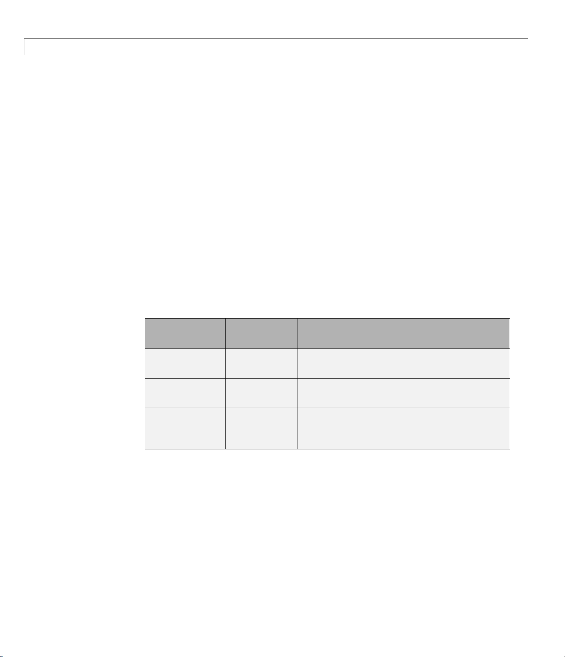
In your module statement, you must specify each port with a direction mode
(input, output, or bidirectional). The following table defines these three modes.
®
Test Bench Environment
1-8
Use VHDL
Mode...
IN input
OUT output
INOUT inout
Use Verilog
Mode...
For Ports That...
Represent signals that can be driven by a
MATLAB function
Represent signal values that are passed to
a MATLAB function
Represent bidirectional signals that can
be driven by or pass values to a MATLAB
function
Specifying Port Data Types in HDL Modules for Use
with Test Bench
This section describes how to specify data types compatible with MATLAB
for ports in your HDL modules. For details on how the EDA Simulator Link
interface converts data types for the MATLAB environment, see “Performing
Data Type Conversions” on page 7-5.
Page 33

Code HDL Modules for Verification Using MATLAB
Note If you use unsupported types, the EDA Simulator Link software issues
a warning and ignores the port at run time. For example, if you define your
interface with f ive ports, one of which is a VHDL access port, at run time,
then the interface displays a warning and your code sees only four ports.
Port Data Types for VHDL Entities
In your entity statement, you must define each port that you plan to test with
MATLAB with a VHDL data type that is supported by the EDA Simulator
Link software. The interface can convert scalar and array data of the
following VHDL types to comparable MATLAB types:
•
STD_LOGIC, STD_ULOGIC, BIT, STD_LOGIC_VECTOR, STD_ULOGIC_VECTOR,
and
BIT_VECTOR
• INTEGER and NATURAL
• REAL
• TIME
• Enumerated types, including user-defined enumerated types and
CHARACTER
The interface also supports all subtypes and arrays of the preceding types.
Note The EDA Simulator Link software does not support VHDL extended
identifiers for the following components:
• Port and signal names used in cosimulation
• Enum literals when used as array indices of port and signal names used
in cosimulation
However, the software does support basic identifiers for VHDL.
1-9
Page 34

1 Simulating an HDL Component in a MATLAB
Port Data Types for Verilog Modules
In your modu le definition, you must defin e each port that you plan to t e s t
with MATLAB with a Verilog port data type that is supported by the EDA
Simulator Link software. The interface can convert data of the following
Verilog port types to comparable MATLAB types:
• reg
• integer
• wire
Note EDA Simulator Link software does not support Verilog escaped
identifiers for port and signal names used in cosimulation. However, it does
support simple identifiers for Verilog.
Compiling and Elaborating the HDL Design for Use with Test Bench
After you create or edit your HDL source files, use the HDL simulator
compiler to compile and debug the code.
®
Test Bench Environment
1-10
Compilation for ModelSim
You have the option of invoking the compiler from menus in the ModelSim
graphic interface or from the command line with the
following sequence of ModelSim commands creates and maps the design
library
The following sequence of ModelSim commands crea t es and maps the design
library
work and compiles the VHDL file modsimrand.vhd:
ModelSim> vlib work
ModelSim> vmap work work
ModelSim> vcom modsimrand.vhd
work and compiles the Verilog file test.v:
ModelSim> vlib work
ModelSim> vmap work work
ModelSim> vlog test.v
vcom command. The
Page 35

Code HDL Modules for Verification Using MATLAB
Note You should provide read/write access to the signals that are connecting
to the MATLAB session for cosimulation. For higher performance, you
want to provide access only to those signals used in cosimulation. You can
check read/write access through the HDL simulator—see HDL simulator
documentation for details.
Compilation for Incisive
The Cadence Incisive simulator allows for 1-step and 3-step processes for HDL
compilation, elaboration, and simulation. The following Cadence Incisive
simulator command compiles the Verilog file test.v:
sh> ncvlog test.v
The following Cadence Incisive simulator command compiles and elaborates
the Verilog design
test.v, and then loads it for si mulation, in a single step:
sh> ncverilog +gui +access+rwc +linedebug test.v
The following sequence of Cadence Incisive simulator commands performs all
thesameprocessesinmultiplesteps:
sh> ncvlog -linedebug test.v
sh> ncelab -access +rwc test
sh> ncsim test
Note You should provide read/write access to the signals that are connecting
to the MATLAB session for cosimulation. The previous example shows
how to provide read/write access to all signals in your design. For higher
performance, you want to provide access only to those signals used in
cosimulation. See the description of the
-access argument to ncelab for details.
+access flag to ncverilog and the
1-11
Page 36

1 Simulating an HDL Component in a MATLAB
Compilation for Discovery
Compilation of source files for use with MATLAB and Discovery is most
easily accomplished using the scripts automatically generated by the EDA
Simulator Link HDL simulator launch command
Examples section of the reference page for
Note You should provide read/write access to the signals that are connecting
to the MATLAB session for cosimulation. For higher performance, you want to
provide access only to those signals used in cosimulation. A tab file is included
in the simulation via the required
For more examples, see the EDA Simulator Link tutorialsanddemos. For
details on using the HDL compiler, see the simulator documentation.
Sample VHDL Entity Definition
This sample VHDL code fragment defines the entity decoder.Bydefault,the
entity is associated with MATLAB test bench function
®
Test Bench Environment
launchDiscovery.Seethe
launchDiscovery.
launchDiscovery property "AccFile".
decoder.
1-12
The keyword
two
IN ports—isum and qsum—and three OUT ports—adj, dvalid,andodata.
PORT marks the start of the entity’s port clause, which defines
The output ports drive signals to MATLAB function input ports for processing.
The input ports receive signals from the MATLAB function output ports.
Both input ports are defined as vectors consisting of five standard logic
values. The output port
consists of only two values. The output ports
adj is also defined as a standard logic vector, but
dvalid and odata are defined as
scalar standard logic ports. For information on how the EDA Simulator Link
interface converts data of standard logic scalar and array types for use in the
MATLAB environment, see “Performing Data Type Conversions” on page 7-5.
ENTITY decoder IS
PORT (
isum : IN std_logic_vector(4 DOWNTO 0);
qsum : IN std_logic_vector(4 DOWNTO 0);
adj : OUT std_logic_vector(1 DOWNTO 0);
dvalid : OUT std_logic;
Page 37

odata : OUT std_logic);
END decoder ;
Code HDL Modules for Verification Using MATLAB
1-13
Page 38

1 Simulating an HDL Component in a MATLAB
®
Test Bench Environment
Code an EDA Simulator Link MATLAB Test Bench Function
In this section...
“Process for Coding MATLAB EDA Simulator Link Functions” on page 1-14
“Syntax of a Test Bench Function” on page 1-15
“Sample MATLAB Test Bench Function” on page 1-15
Process for Coding MATLAB EDA Simulator Link Functions
Coding a MATLAB function that is to verify an HDL module or component
requires that you follow specific coding conventions. You must also
understand the data type conversions that occur, and program data type
conversions for operating on data and returning data to the HDL simulator.
To code a MATLAB function that is to verify an HDL module or component,
perform the following steps:
1-14
1 Learn the syntax for a MATLAB EDA Simulator Link test bench function
(see “Syntax of a Test Bench Function” on page 1-15).
2 Understand how E DA Simulator Link software converts data from the
HDL simulator for use in the MATLAB environment (see “Performing
Data Type Conversions” on page 7-5).
3 Choos
4 Define expected parameters in the function definition line (see “MATLAB
5 Determine the types of port data being passed into the function (see
6 Ex
e a name for the MATLAB function (see “Binding the HDL Module
Compo
Function Syntax and Function Argument Definitions” on page 7-42).
“MATLAB Function Syntax and Function Argument Definitions” on page
7-42).
in
In
nent to the MATLAB Test B ench Function” on page 1-29).
tract and, if appropriate for the simulation, apply information received
the
portinfo structure (see “Gaining Access to and Applying Port
formation” on page 7-45).
Page 39

Code an EDA Simulator Link™ MATLAB®Test Ben c h F unct i on
7 Convert data for manipulation in the MATLAB environment, as necessary
(see “Converting HDL Data to Send to MATLAB” on page 7-5 ).
8 Convert data that needs to be returned to the HDL simulator (see
“Converting Data for Return to th e HDL Simulator” on page 7-10).
Syntax of a Test Bench Function
The syntax of a MATLAB test bench function is
function [iport, tnext] = MyFunctionName(oport, tnow, portinfo)
See the “MATLAB Function Syntax and Function Argument Definitions” on
page 7-42 for an explanation of each of the function arguments.
Sample MATLAB Test Bench Function
This section uses a sample MATLAB function to identify sections of a
MATLAB test bench function required by the EDA Simulator Link software.
Youcanseethefulltextofthecodeusedinthissampleinthesection
MATLAB Function Example: manchester_decoder.m on page 1-20.
For ModelSim Users This example uses a VHDL entity and MATLAB
function code drawn from the decoder portion of the Manchester Receiver
demo. For the complete VHDL and function code listings, see the following
files:
matlabroot\toolbox\edalink\extensions\modelsim\modelsimdemos\vhdl\manchester\decoder.vhd
matlabroot\toolbox\edalink\extensions\modelsim\modelsimdemos\manchester_decoder.m
As the first step to coding a MATLAB test bench function, you must
understand how the data modeled in the VH D L entity maps to data in the
MATLAB environment. The VHDL entity
ENTITY decoder IS
PORT (
isum : IN std_logic_vector(4 DOWNTO 0);
qsum : IN std_logic_vector(4 DOWNTO 0);
decoder is defined as follows:
1-15
Page 40

1 Simulating an HDL Component in a MATLAB
adj : OUT std_logic_vector(1 DOWNTO 0);
dvalid : OUT std_logic;
odata : OUT std_logic
);
END decoder ;
The following discussion highlights key lines of code in the definition of the
manchester_decoder MATLAB function:
1 Specify the MATLAB function name and required parameters.
®
Test Bench Environment
The following code is the function declaration of the
manchester_decoder
MATLAB function.
function [iport,tnext] = manchester_decoder(oport,tnow,portinfo)
See “MATLAB Function Syntax and Function Argum ent Definitions” on
page 7-42.
The function declaration performs the following actions:
• Names the function. This declaration names the function
manchester_decoder, which differs from the entity name decoder.
Because the names differ, the functionnamemustbespecifiedexplicitly
later when the entity is initialized for verification with the
matlabtbeval function. See “Binding the HDL Module Component to
matlabtb or
the MATLAB Test Bench Function” on page 1-29.
• Defines required argument and return param eters. A MATLAB test
bench function must return two parameters,
three arguments,
oport, tnow,andportinfo,andmust appear in the
iport and tnext,andpass
order shown. See “MATLAB Function Syntax and Function Argument
Definitions” on page 7-42.
The function outputs must be initialized to empty values, as in the
following code example:
tnext = [];
iport = struct();
1-16
You should initialize the function outputs at the beginning of the
function, to follow recommended best practice.
Page 41
Code an EDA Simulator Link™ MATLAB®Test Ben c h F unct i on
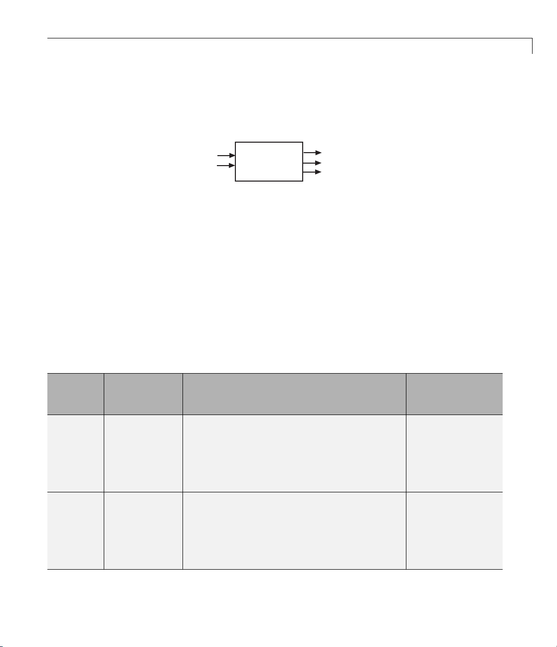
The following figure shows the relationship between the entity’s ports
and the MATLAB function’s
iport and oport parameters.
Input Signals
iport.isum (5)
iport.qsum (5)
decoder.vhd
Output Signals
oport.adj (2)
oport.dvalid(1)
oport.odata(1)
For more information on the required MATLAB test bench function
parameters, see “MATLAB Function Syntax and Function Argument
Definitions” on page 7-42.
2 Make note of the data types of ports defined for the entity being
simulated.
The ED A Simulator Link software converts HDL data types to comparable
MATLAB data types and vice versa. As you develop your MATLAB
function, you must know the types of the data that it receives from the
HDL simulator and needs to return to the HDL simulator.
The VHDL entity defined for this example consists of the following ports
VHDL Ex ample Port De fin itio ns
Port
isum IN STD_LOGIC_VECTOR(4 DOWNTO 0)
qsum IN STD_LOGIC_VECTOR(4 DOWNTO 0)
Direction
Type...
Converts
to/Requires
Conversion to...
A5-bitcolumn
or row vector of
characters where
each bit maps to
astandardlogic
character literal.
A5-bitcolumn
or row vector of
characters where
each bit maps to
astandardlogic
character literal.
1-17
Page 42

1 Simulating an HDL Component in a MATLAB
®
VHDL Example Port Definitions (Continued)
Test Bench Environment
Port
adj OUT STD_LOGIC_VECTOR(1 DOWNTO 0)
dvalid OUT STD_LOGIC
odata OUT STD_LOGIC
Direction
Type...
Converts
to/Requires
Conversion to...
A2-element
column vector of
characters. Each
character matches
a corresponding
character literal
that represents
alogicstateand
maps to a single
bit.
A character that
matches the
character literal
representing the
logic state.
A character that
matches the
character literal
representing the
logic state.
1-18
For more information on interface data type conversions, see “Performing
Data Type Co nvers ions” on page 7-5.
3 Set up any required timing parameters.
The
tnext assignment statem ent sets up timing parameter tnext such
that the simulator calls back the MATLAB function every nanosecond.
tnext = tnow+1e-9;
4 Convert output port data to appropriate MATLAB data types for
processing.
Page 43

Code an EDA Simulator Link™ MATLAB®Test Ben c h F unct i on
The following code excerpt illustrates data ty pe conversion of output port
data.
%% Compute one row and plot
isum = isum + 1;
adj(isum) = mvl2dec(oport.adj');
data(isum) = mvl2dec([oport.dvalid oport.odata]);
.
.
.
The two calls to mvl2dec convert the binary data that the MATLAB
function receives from the entity’s output ports,
adj, dvalid,andodata to
unsigned decimal values that MATLAB can compute. The function converts
the 2-bit transposed vector
4and
oport.dvalid and oport.odata to the decimal value 0 or 1.
oport.adj toadecimalvalueintherange0to
“Defining EDA Simulator Link MATLAB Functions and Function
Parameters” on page 7-42 provides a summary of the types of data
conversions to consider when coding simulation MATLAB functions.
5 Convert data to be returned to the HDL simulator.
The following code excerpt illustrates data type conversion of data to be
returned to the HDL simulator.
if isum == 17
iport.isum = dec2mvl(isum,5);
iport.qsum = dec2mvl(qsum,5);
else
iport.isum = dec2mvl(isum,5);
end
The three calls to dec2mvl convert the decimal values computed by
MATLAB to binary data that the MATLAB function can deposit to the
entity’s input ports,
isum and qsum. Ineachcase,thefunctionconvertsa
decimal value to 5-element bit vector with each bit representing a character
that m aps to a character literal representing a logic state.
1-19
Page 44

1 Simulating an HDL Component in a MATLAB
“Converting Data for Return to the HDL Simulator” on page 7-10 provides
a summary of the types of data conversions to consider when returning
data to the HDL simulator.
MATLAB Function Example: manchester_decoder.m
®
Test Bench Environment
1-20
Page 45

Place Test Bench Function on MATLAB Search Path
Place Test Bench Function on MATLAB Search Path
In this section...
“Use MATLAB which Function to Find Test Bench” on page 1-21
“Add Test Bench Function to MATLAB Search Path” on page 1-21
Use MATLAB which Function to Find Test Bench
The MATLAB function that you are associating with an HDL component must
be on the MATLAB search path or reside in the current working folder (see
the MATLAB
the MATL AB
function
which MyVhdlFunction
/work/incisive/MySym/MyVhdlFunction.m
If the specified function is on the search path, which displays the complete
path to the function. If the function is not on the search path,
you that the file was not found.
cd function). To verify whether the function is accessible, use
which function. The following call to which checks whether the
MyVhdlFunction is on the MATLAB search path, for example:
which informs
Add Test Bench Function to MATLAB Search Path
To add a M ATLA B function to the MATLAB search path, open the Set
Path window by clicking File > Set Path,orusethe
Alternatively, for temporary access, you can change the MATLAB working
folder to a desired location with the
cd command.
addpath command.
1-21
Page 46

1 Simulating an HDL Component in a MATLAB
®
Test Bench Environment
Start Connection to HDL Simulator for Test Bench Session
In this section...
“Start MATLA B Server for Test Bench Session” on page 1-22
“Example of Starting MATLAB Server for Test Bench Session” on page 1-23
Start MATLAB Server for Test Bench Session
Start the MATLAB server as follows:
1 Start MATLAB.
2 In the MATLAB Command Window, call the hdldaemon function with
property name/property value pairs that specify whether the EDA
Simulator Link software is to perform the following tasks:
• Use shared m emo ry or TCP/IP socket communication
• Return time values in seconds or as 64-bit integers
1-22
See
hdldaemon reference documentation for when and how to specify property
name/property value pairs and for more examples of using
The communication mode that you specify (shared memory or TCP/IP sockets)
must match what you specify for the communication mode when you initialize
the HDL simulator for use with a MATLAB link session using the
or matlabcp function. In addition, if you specify TCP/IP socket mode, the
socket port that you specify with
match. For more information on modes of communication, see “Specifying
TCP/IP Socket Communication” on page 6-29.
TheMATLABservercanservicemultiple simultaneous HDL simulator
modules and clients. However, your code must track the I/O associated with
each entity or client.
hdldaemon and matlabtb or matlabcp must
hdldaemon.
matlabtb
Page 47

Start Connection to HDL Simulator for Test Bench Session
Note You cannot begin an EDA Simulator Link transaction between
MATLAB and the HDL simulator from MATLAB. The MATLAB server simply
responds to function call requests that it receives from the HDL simulator.
Example of Starting MATLAB Server for Test Bench Session
The following com mand specifies using socket communication on port 4449
and a 64-bit time resolution format for the MATLAB function’s output ports.
hdldaemon('socket', 4449, 'time', 'int64')
1-23
Page 48

1 Simulating an HDL Component in a MATLAB
®
Test Bench Environment
Launch HDL Simulator for Use with MATLAB Test Bench
In this section...
“Launching the HDL Simulator for Test Bench Session” on page 1-24
“Loading an HDL Design for Verification” on page 1-24
Launching the HDL Simulator for Test Bench Session
Start the HDL simulator directly from MATLAB by calling the M ATLAB
function
Link with HDL Simulators ” for instructions on starting the HDL simulator
for use with EDA Simulator Link.
Loading an HDL Design for Verification
After you start the HDL simulator from MATLAB with a call to vsim or
nclaunch, load an instance of an HDL module for verification or visualization
with the function
start the HDL simulator from MATLAB and load an instance of an HDL
module for verification with a call to
'PropertyValue'...)
your HDL model. Issue the function
instance of an entity or module in your model that you want to cosimulate.
For example (for use with Incisive):
vsim, nclaunch,orlaunchDiscovery. See “Using EDA Simulator
vsimmatlab or hdlsimmatlab. If you are using Discovery,
launchDiscovery('PropertyType',
. At this p oint, you should have coded and compiled
vsimmatlab or hdlsimmatlab for each
1-24
hdlsimmatlab work.osc_top
This command loads the EDA Simulator Link library, opens a simulation
workspace for
simulator command window as the simulator loads the entity (see demo for
remaining code).
Another example is (for use with Discovery):
launchDiscovery( ...
'VerilogFiles','osc_top.v', ...
'TopLevel', 'osc_top', ...
'RunMode','GUI', ...
'RunDir',projdir,...
osc_top, and displayd a series of me ssages in the HDL
Page 49

Launch HDL Simulator for Use with MATLAB Test Bench
'LinkType','MATLAB',...
'PreSimTcl', preSimTclCmds, ...
'AccFile',tabaccessfile,...
'VlogAnFlags', '"+v2k"' ...
);
This command loads osc_top in the HDL simulator and executes the
preSimTclCmds commands (see Oscillator demo for remaining code).
1-25
Page 50

1 Simulating an HDL Component in a MATLAB
®
Test Bench Environment
Invoke matlabtb to Bind MATLAB Test Bench Function Calls
In this section...
“Invoking the MATLAB T est Bench Comm and matlabtb” on page 1-26
“Binding the HDL Module Component to the MATLAB Test Bench
Function” on page 1-29
Invoking the MATLAB Test Bench Command matlabtb
You invoke matlabtb by issuing the command in the HDL simulator. See
the Examples section of the
of invoking
Be sure to follow the path specifications for MATLAB test bench sessions
when invoking
Module Paths for MA TLAB Test Bench Cosimulation” on page 1-26.
matlabtb.
matlabtb, as explained in “Specifying HDL Signal/Port and
matlabtb reference page for several examples
For instructions in issuing the
Bench Cosimulation” on page 1-36.
matlabtb command, see “Running a Test
Specifying HDL Signal/Port and Module Paths for MATLAB Test
Bench C
EDA Simulator Link software has specific requirements for specifying HDL
design hierarchy, the syntax of which is described in the following sections:
one for Verilog at the top level, and one for VHDL at the top level. Do not use
a file name hierarchy in place of the design hierarchy name.
The rules stated in this section apply to signal/port and module path
specifications for MATLAB l in k sessions. Other specifications m ay work but
the EDA Simulator Link software does not officially recognize nor support
them.
In the following example:
matlabtb u_osc_filter -mfunc oscfilter
u_osc_filter is the top-level component. If you specify a subcompone n t, you
must follow valid module path specifications for MATLAB link sessions.
osimulation
1-26
Page 51

Invoke matlabtb to Bind MATLAB Test Bench Function Calls
Path Specifications for MATLAB Link Sessions with Verilog Top Level.
• The path specification must start w ith a top-level module name.
• The path specification can include "." or "/" path delimiters, but it cannot
include mixed delimiters.
• The leaf m odule or signal must match the HDL language of the top-level
module.
The following examples show valid signal an d module path specifications:
top.port_or_sig
/top/sub/port_or_sig
top
top/sub
top.sub1.sub2
The following examples show invalid signal and module path specifications:
•
top.sub/port_or_sig
Why this specification is invalid: You cannot use mixed delimiters.
:sub:port_or_sig
•
:
:sub
Why this specification is invalid: When you use VHDL-specific delimiters
you limit the interoperability with paths when moving between HDL
simulators and between VHDL and Verilog.
Path Specifications for MATLAB Link Sessions with VHDL Top Level.
• The path specification can include the top-level module name, but you do
nothavetoincludeit.
• The path specification can include "." or "/" path delimiters, but it cannot
include mixed delimiters.
• The leaf m odule or signal must match the HDL language of the top-level
module.
1-27
Page 52

1 Simulating an HDL Component in a MATLAB
Examples for ModelSim and Incisive Users
The following examples show valid signal an d module path specifications:
top.port_or_sig
/sub/port_or_sig
top
top/sub
top.sub1.sub2
The following examples show invalid signal and module path specifications:
•
top.sub/port_or_sig
Why this specification is invalid: You cannot use mixed delimiters.
:sub:port_or_sig
•
:
:sub
®
Test Bench Environment
1-28
Why this specification is invalid: When you use VHDL-specific delimiters
you limit the interoperability with paths when moving between HDL
simulators and between VHDL and Verilog.
Examples for Discovery Users
The following examples show valid signal an d module path specifications:
top.port_or_sig
top
top/sub
top.sub1.sub2
The following examples show invalid signal and module path specifications:
•
top.sub/port_or_sig
Why this specification is invalid: You cannot use mixed delimiters.
/sub/port_or_sig
•
Why this specification is invalid: You have not specified the top level.
Page 53

Invoke matlabtb to Bind MATLAB Test Bench Function Calls
• :sub:port_or_sig
:
:sub
Why this specification is invalid: When you use VHDL-specific delimiters
you limit the interoperability with paths when moving between HDL
simulators and between VHDL and Verilog.
Binding the HDL Module Component to the MATLAB
Test Bench Function
Bydefault,theEDASimulatorLinksoftwareassumesthatthenamefora
MATLAB function matches the name of the HDL module that the function
verifies. When you create a test bench or component function that has a
different name than the design under test, you must associate the design
with the MATLAB function using the -mfunc argument to
argument associates the HDL module instance to a MATLAB function that
has a different name from the HDL instance.
matlabtb.This
For more information on the -mfunc argument and for a full list of
parameters, see the matlabtb function reference.
For details on MATLAB function naming guidelines, see "MATLAB
Programming Tips" on files and file names in the MATLAB documentation.
matlabtb
Example of Binding Test Bench and Component Function Calls
In this first example, you form an as sociation between the inverter_vl
component and the MATLAB test bench function inverter_tb by invoking the
function
The matlabtb command instructs the HDL simulator to call back the
inverter_tb function when inverter_vl executes in the simulation.
In this second example, you bind the model osc_top.u_osc_filter to the
component function oscfilter:
matlabtb with the -mfunc argument when y ou set up the simulation.
matlabtb inverter_vl -mfunc inverter_tb
matlabcp osc_top.u_osc_filter -mfunc oscfilter
1-29
Page 54

1 Simulating an HDL Component in a MATLAB
When the HDL simulator calls the oscfilter callback, the function knows to
operate on the model osc_top.u_osc_filter.
®
Test Bench Environment
1-30
Page 55

Schedule Options for a Test Bench Session
Schedule Options for a Test Bench Session
In this section...
“About Scheduling Options for Test Bench Sessions” on page 1-31
“Scheduling Test Bench Session Using matlabtb Arguments” on page 1-31
“Scheduling Test Bench Functions Using the tnext Parameter” on page 1-32
About Scheduling Options for Test Bench Sessions
TherearetwowaystoscheduletheinvocationofaMATLABfunction:
• Using the arguments to the EDA Simulator Link function
matlabcp
• Inside the MATLAB function using the tnext parameter
The two types of scheduling are not mutually exclusive. You can combine
the
matlabtb or matlabcp timing arguments and the tnext parameter of a
MATLAB function to schedule test ben ch or co mpo nent session callbacks.
matlabtb or
Scheduling Test Bench Session Using matlabtb Arguments
By default, the EDA Simulator Link software invokes a MATLAB test
bench or component function once (at the time that you make the call to
matlabtb/matlabcp). If you want to apply more control, and execute the
MATLAB function more than once, use the command scheduling options.
With these options, you can specify when and how often the EDA Simulator
Link software invokes the relevant MATLAB function. If necessary, modify
the function or specify timing arguments when you begin a MATLAB test
bench or component function session with the
You can schedule a MATLAB test bench or component function to execute
using the command arguments under any of the following conditions:
• Discrete time values—Ba sed on time specifications that can also include
repeat intervals and a stop time
matlabtb/matlabcp function.
• Rising edge—When a specified signal experiences a rising edge
1-31
Page 56

1 Simulating an HDL Component in a MATLAB
- VHDL: Rising edge is {0 or L} to {1 or H} .
- V erilog: Rising edge is the transition from 0 to x, z, or 1, and from x
or z to 1.
• Falling edge—When a specified signal experiences a falling edge
- V H DL: Falling edge is {1 or H } to {0 or L}.
- Verilog: Falling edge i s the transition from 1 to x, z, or 0, and from
xorzto0.
• Signal state change—When a specified signal changes state, based on a
list using the -sensitivity argument to
Scheduling Test Bench Functions Using the tnext Parameter
You can control the callback timing of a MATLAB function by using that
function’s
simulator, and the value gets added to the simulation schedule for that
function. If the function returns a null value ([]) , the software does not add
any new entries to the schedule.
tnext parameter. This parameter passes a time value to the HDL
®
Test Bench Environment
matlabtb.
1-32
You can set the value of
double to express the callback time in seconds. For example, to schedule
acallbackin1ns,specify::
tnext = 1e-9
Specify int64 to convert to a n integer multiple of the curre nt HDL simulator
time resolution limit. For example: if the HDL simulator time precision is 1
ns, to schedule a callback at 100 ns, specify:
tnext=int64(100)
tnext to a value of type double or int64.Specify
Page 57

Schedule Options for a Test Bench Session
Note The tnext parameter represents time from the start of the simulation.
Therefore,
tnext m ust always be greater than tnow. If it is less, the software
does not schedule a callback.
For more information on tnext and the function prototype, see “Defining EDA
Simulator Link MATLAB Functions and Function Parameters” on page 7-42.
Examples of Scheduling with tnext
In this first example, each time the HDL simulator calls the test bench
function (via EDA Simulator Link), tnext schedules the next callback to the
MATLAB function for 1 ns later, relative to the current simulation time:
tnext = [];
.
.
.
tnext = tnow+1e-9;
Using tnext you can dynamically decide the callback scheduling based on
criteria specific to the operation of the test bench. For example, you can decide
to stop scheduling callbacks when a data signal has a certain value:
if qsum == 17,
qsum = 0;
disp('done');
tnext = []; % suspend callbacks
testisdone = 1;
return;
end
This next example demonstrates scheduling a component session using
tnext. In the Oscillator demo, the oscfilter function calculates a time interval
at which the HDL simulator calls the callbacks. The component function
calculates this interval on the first call to oscfilter and stores the result in the
variable fastestrate. The variable fastestrate represents the sample period of
the fastest oversampling rate supported by the filter. The function derives
this rate from a base sampling period of 80 ns.
1-33
Page 58

1 Simulating an HDL Component in a MATLAB
The following assignment statement sets the timing parameter tnext. This
parameter schedules the next callback to the MATLAB component function,
relative to the current simulation time (tnow).
tnext = tnow + fastestrate;
The function returns a new value for tnext each time the HDL simulator
calls the function.
®
Test Bench Environment
1-34
Page 59

RunMATLABTestBenchSimulation
In this section...
“Process for Running MATLAB Test B ench Cosimulation” on page 1-35
“Checking the MATLAB Server’s Link Status for Test Bench Cosimulation”
on page 1-35
“Running a Test Bench Cosimulation” on page 1-36
“Applying Stimuli to Test Bench Session with the HDL Simulator force
Command” on page 1-41
“Restarting a Test Bench Simulation” on page 1-43
Process for Running MATLAB Test Bench Cosimulation
To start and control the execution of a simulation in the MATLAB
environment, perform the following steps:
Run MATLAB Test Bench Simulation
1 “Checking the MATLAB Server’s L ink Status for Test Bench Cosimulation”
on page 1-35
2 Run and mo nitor the cosimulation session.
3 Apply
4 Restart simulator during a cosimulation session (if necessary).
stimuli (optional).
Checking the MATLAB Server’s Link Status for Test
Bench Cosimulation
The first step to starting an HDL simulator and MATLAB test bench or
component function session is to check the MATLAB server’s link status. Is
the server running? If the server is running, what mode of communication
and, if applicable, w hat TCP/IP socket port is the server using for its links?
You can retrieve this information b y using the MATLAB function
with the 'status' option. F or example:
hdldaemon('status')
hdldaemon
1-35
Page 60

1 Simulating an HDL Component in a MATLAB
The function displays a m essage that indicates whether the server is running
and, if it is running, the number of connections it is handling. For example:
HDLDaemon socket server is running on port 4449 with 0 connections
If the server is not running, the message reads
HDLDaemon is NOT running
See the Options: Inputs section in the hdldaemon reference documentation
for information on determining the mode of communication and the TCP/IP
socket in use.
Running a Test Bench Cosimulation
YoucanrunacosimulationsessionusingboththeMATLABandHDL
simulator GUIs (typical) or, to reduce memory demand, you can run the
cosimulation using the command line interface (CLI) or in batch mode.
®
Test Bench Environment
1-36
• “Cosimulation with MATLAB Using the HDL Simulator GUI” on page 1-36
• “Cosimulation with MATLAB Using the Command Line Interface (CLI)”
on page 1-38
• “Cosimulation with M ATLA B Using Batch Mode” on page 1-40
Cosimulation with MATLAB Using the HDL Simulator GUI
These steps describe a typical sequence for running a s imulation interactively
from the main HDL simulator window:
1 SetbreakpointsintheHDLandMATLABcodetoverifyandanalyze
simulation progress and correctness.
How you set breakpoints in the HDL simulator will vary depending on
what simulator application you are using.
In MAT LAB, there are several w ays you can set breakpoints; for example,
by using the Set/Clear Breakpoint button on the toolbar.
2 Issue matlabtb command at the HDL simulator prompt.
Page 61

Run MATLAB Test Bench Simulation
When you begin a specific test bench or component sessio n, you specify
parameters that identify the following informat ion :
• The mode and, if appropriate, TCP/IP data necessary for connecting to a
MATLAB server (see
matlabtb reference)
• The MATLAB function that is associated with and executes on behalf
of the HDL instance (see “Binding the HDL Module Component to the
MATLAB Test Bench Function” on page 1-29)
• Timing specifications and other control data that specifies when the
module’s MATLAB function is to be called (see “Schedule Options for a
Test Bench Session” on page 1-31)
For example:
hdlsim> matlabtb osc_top -sensitivity /osc_top/sine_out
-socket 4448 -mfunc hosctb
3 Start the simulation by entering the HDL simulator run command.
The
run comm and offers a variety of options for applying control over how
a simulation runs (refer to your HDL simulator documentation for details).
For example, you can specify that a simulation run for several time steps.
The following command instructs theHDLsimulatortoruntheloaded
simulation for 50000 time steps:
run 50000
4 Step through the simulation and examine values.
How you step through the simulation in the HDL simulator will vary
depending on what simulator application you are using.
In MATLAB, there are several w ays you can step through code; for
example, by clicking the Step toolbar button.
5 When you block execution of the MATLAB function, the HDL simulator
also blocks and remains blocked until you clear all breakpoints in the
function’s code.
6 Resume the simulation, as needed.
1-37
Page 62

1 Simulating an HDL Component in a MATLAB
How you resume the simulation in the HDL simulator will vary depending
on what simulator application you are using.
In MATLAB, there are several ways you can resume the simulation; for
example, by clicking the Continue toolbar button.
The following HDL simulator command resumes a simulation:
run -continue
For more information on HDL simulator and MATLAB debugging features,
see the appropriate HDL simulator documentation and MATLAB online help
or documentation.
Cosimulation with MATLAB Using the Command Line Interface (CLI)
Running your cosimulation session using the command-line interface allows
you to interact with the HDL simulator during cosimulation, which can be
helpful for debugging.
®
Test Bench Environment
1-38
To use the CLI, specify "CLI" as the property value for the run mode
parameter of the EDA Simulator Link HDL simulator launch command.
The Tcl command you build to pass to the HDL simulator launch command
must contain the run command or no cosimulation will take place.
Caution Close the terminal window by entering "quit -f" at the command
prompt. Do not close the terminal window by clicking the "X" in the upper
right-hand corner. This causes a memory-type error to be issued from the
system. This is not a bug with EDA Simulator Link but just the way the
HDL simulator behaves in this context.
You can type CTR L+C to interrupt and terminate the simulation in the HDL
simulator but this action also causes the memory-type error to be displayed.
Page 63

Run MATLAB Test Bench Simulation
Specifying CLI mode with ncl au nch (for use with Cadence Incisive)
Issue the
nclaunch command with "CLI" as the runmode property value, as
follows (example entered into the MATLAB editor):
tclcmd = { ['cd ',projdir],...
['exec ncvlog ' srcfile],...
'exec ncelab -access +wc lowpass_filter',...
['hdlsimmatlab -gui lowpass_filter ', ...
' -input "{@matlabtb lowpass_filter 10ns -repeat 10ns -mfunc filter_tb_incisive}"',...
' -input "{@force lowpass_filter.clk_enable 1 -after 0ns}"',...
' -input "{@force lowpass_filter.reset 1 -after 0ns 0 -after 22ns}"',...
' -input "{@force lowpass_filter.clk 1 -after 0ns 0 -after 5ns -repeat 10ns}"',...
' -input "{@deposit lowpass_filter.filter_in 0}"',...
]};
nclaunch('tclstart',tclcmd,'runmode','CLI');
Specifying CLI mode with vsim (for use with Mentor Graphics
ModelSim)
Issue the
vsim command with "CLI" as the runmode property value, as follows
(example entered into the MATLAB editor):
tclcmd = { ['cd ',unixprojdir],...
'vlib work',... %create library (if necessary)
'force /osc_top/clk_enable 1 0',...
'force /osc_top/reset 1 0, 0 120 ns',...
'force /osc_top/clk 1 0 ns, 0 40 ns -r 80ns',...
};
vsim('tclstart',tclcmd,'runmode','CLI');
Specifying CLI mode with launchDiscovery (for use with Synopsys
Discovery)
Issue the
launchDiscovery command with "CLI" as the RunMode parameter,
as follows:
preSimTclCmds = { ...
'matlabtb lowpass_filter 10ns -repeat 10ns -mfunc lpfiltertestbench',...
1-39
Page 64

1 Simulating an HDL Component in a MATLAB
'force lowpass_filter.clk_enable 1 0ns',...
'force lowpass_filter.reset 1 0ns, 0 22ns',...
'force lowpass_filter.clk 1 0ns, 0 5ns -repeat 10ns',...
'force lowpass_filter.filter_in 0 -deposit'...
};
launchDiscovery( ...
'VerilogFiles',srcfile, ...
'TopLevel', 'lowpass_filter', ...
'RunMode','CLI', ...
'RunDir',projdir,...
'LinkType','MATLAB',...
'PreSimTcl', preSimTclCmds, ...
'AccFile',tabaccessfile,...
'VlogAnFlags', '"+v2k"' ...
);
Cosimulation with MATLAB Using Batch Mode
Running your cosimulation session in batch mode allows you to keep the
process in the background, reducing demand on memory by disengaging the
GUI.
®
Test Bench Environment
1-40
To use the batch mode, specify "Batch" as the property value for the run mode
parameter of the EDA Simulator Link HDL simulator launch command.
After you issue the EDA Simulator Link HDL simulator launch command
with batch mode specified, start the simulation in Simulink. To stop the
HDL simulator before the simulation is completed, issue the
breakHdlSim
command.
Specifying Batch mode with ncl au nc h (for use with Cadence Incisive)
Issue the
nclaunch command with "Batch" as the runmode parameter, as
follows:
nclaunch('tclstart',manchestercmds,'runmode','Batch')
You can also set runmode to "Batch with Xterm", which starts the HDL
simulator in the background but shows the session in an Xterm.
Page 65

Run MATLAB Test Bench Simulation
Specifying Batch mode with vsim (for use with Mentor Graphics
ModelSim)
On Windows, specifying batch mode causes ModelSim to be run in a
non-interactive command window. On Linux, specifying batch mode causes
Modelsim to be run in the background with no window.
Issue the
>> vsim('tclstart',manchestercmds,'runmode','Batch')
vsim command with "Batch" as the runmode parameter, as follows:
Specifying Batch mode w ith launchDiscovery (for use with Synopsys
Discovery)
Issue the
launchDiscovery command with "Batch" as the RunMode
parameter, as follows:
pv = launchDiscovery( ...
'LinkType', 'Simulink', ...
langParam, 'vlog', ...
'TopLevel', 'gainx2', ...
'RunMode', 'Batch', ...
'PreSimTcl', {'force clk 0 0, 1 1 -repeat 2'}, ...
'AccFile', [srcbase '/gainx2.pli_acc.tab'] ...
You can also set RunMode to "Batch with Xterm", which starts the HDL
simulator in the background but shows the session in an Xterm.
Applying Stimuli to Test Bench Session with the HDL
Simulator force Command
After you establish a link betw een the HD L simulator and MATLAB, you can
then apply stimuli to the test bench or component cosimulation environment.
One way of applying stimuli is through the
MATLAB function. This parameter forces signal values by deposit.
iport parameter of the linked
Other ways to apply stimuli include issuing
force commands in the HDL
simulator main window (for ModelSim, you can also use the Ed it > Clock
option in the ModelSim Signals window).
1-41
Page 66

1 Simulating an HDL Component in a MATLAB
For exam ple, consider the following sequence of force comm ands:
• Incisive
force osc_top.clk_enable 1 -after 0ns
force osc_top.reset 0 -after 0ns 1 -after 40ns 0 -after 120ns
force osc_top.clk 1 -after 0ns 0 -after 40ns -repeat 80ns
• ModelSim
VSIM n> force clk 0 0 ns, 1 5 ns -repeat 10 ns
n> force clk_en 1 0
VSIM
n> force reset 0 0
VSIM
• Discovery
force osc_top.clk_enable 1 -after 0ns
force osc_top.reset 0 -after 0ns 1 -after 40ns 0 -after 120ns
force osc_top.clk 1 -after 0ns 0 -after 40ns -repeat 80ns
®
Test Bench Environment
1-42
Thesecommandsdrivethefollowingsignals:
• The
clk signal to 0 at 0 nanoseconds after the current simulation time
and to 1 at 5 nanoseconds after the current HDL simulation time. This
cycle repeats starting at 10 nanoseconds after the current simulation
time, causing transitions from 1 to 0and0to1every5nanoseconds,as
the following diagram shows.
1
0
t
0
5
10
20
...
30
For example,
force /foobar/clk 0 0, 1 5 -repeat 10
• The clk_en signal to 1 at 0 nanoseconds after the current simulation time.
• The
reset signal to 0 at 0 nanoseconds after the current simulation time.
Page 67

Run MATLAB Test Bench Simulation
Incisive Users: Using HDL to Code Clock Signals Instead of
the force Command
You should consider using HDL to code clock signals as force is a lower
performance solution in the current version of Cadence Incisive simulators.
Thefollowingarewaysthataperiodic force might be introduced:
• Via the Clock pane in the HDL Cosimulation block
• Via pre/post Tcl commands i n the HDL Cosimulation block
• Via a user-input Tcl script to ncsim
All three approaches may lead to performance degradation.
Restarting a Test Bench Simulation
Because the HDL simulator issues the service requests during a MATLAB
cosimulation session, you must restart the session from the HDL simulator.
To restart a session, perform the following steps:
1 Make the HDL simulator your active window, if your input focus was not
already set to that application.
2 Reload HDL design elements and reset the simulation tim e to zero.
3 Incisive and ModelSim Users: Reissue the matlabtb or matlabcp
command.
4 Discovery Users: Call the restart command. restart also sources
(runs) the pre-Tcl commands specified in
matlabtb or matlabcp was included in the pre-Tcl commands, there is
launchdiscovery. Therefore, if
no need to call the function again.
Note To restart a simulation that is in progress, issue a break command and
end the current s imulation session before restarting a new session.
1-43
Page 68

1 Simulating an HDL Component in a MATLAB
Stop Test Bench Simulation
When you are ready to stop a test bench session, it is best to do so i n an orderly
way to avoid possible corru ption of files and to ensure that all application
tasks shut down appropriately. You should stop a session as follow s:
1 Make the HDL simulator your active window, if your input focus was not
already set to that application.
2 Halt the simulation. You must quit the simulation at the HDL simulator
side or MATLAB may hang until the simulator is quit.
®
Test Bench Environment
3 Close your p
4 Exit the HDL simulator, if you are finished with the application.
5 Quit MATLAB, if you are finished with the application. If you want to
shut down the server manually, stop the server by calling
the
'kill' option:
hdldaemo
roject.
hdldaemon with
n('kill')
For more information on closing HDL simulator sessions, see the HDL
simulator documentation.
1-44
Page 69

Tutorial – Running a Sample ModelSim and MATLAB®Test Bench Session
Tutorial – Running a Sample ModelSim and MATLAB Test
Bench Session
In this section...
“Tutorial Overview” on page 1-45
“Setting Up Tutorial Files” on page 1-46
“Starting the MATLAB Server” on page 1-46
“Setting Up the ModelSim Simulator” on page 1-47
“Developing the VHDL Code” on page 1-49
“Compiling the VHDL File” on page 1-51
“Developing the MATLAB Function” on page 1-52
“Loading the Simulation” on page 1-54
“Running the Simulation” on page 1-56
“Shutting Down the Simulation” on page 1-61
Tutor
This t
Simu
In th
numb
VHD
Not
Mo
im
tu
T
M
ial Overview
utorial guides you through the basic steps for setting up an EDA
lator Link application that uses MATLAB to verify a simple HDL design.
is tu torial, you de velop, simulate, and verify a model of a pseudorandom
er generator based on the Fibonacci sequence. The model is coded in
L.
e This tutorial demonstrates creating and running a test bench using
delSim SE 6.5. If you are not using this version, the messages and screen
ages from ModelSim may not appear to you exactly as they do in this
torial.
his tutorial requires MATLAB, the EDA Simulator Link software, and the
odelSim HDL simulator.
1-45
Page 70

1 Simulating an HDL Component in a MATLAB
®
Test Bench Environment
Setting Up Tutor
To ensure that ot
foryourowntuto
1 Create a folder
which you can c
tutorial assu
2 Copy the following files to the folder you just created:
matlabroot\toolbox\edalink\extensions\modelsim\modelsimdemos\modsimrand_plot.m
matlabroot\toolbox\edalink\extensions\modelsim\modelsimdemos\VHDL\modsimrand\
modsimrand.vhd
mes that you create a folder named
ial Files
hers can access copies of the tutorial files, set up a folder
rial work:
outside the scope of your MATLAB installation folder into
opy the tutorial files. The folder must be writable. This
MyPlayArea.
Starting the MATLAB Server
This section describes starting MATLAB, setting up the current folder for
completing the tutorial, starting the product’s MATLAB server component,
and checking for client connections, using shared memory or the server’s
TCP/IP socket mode. These instructions assume you are familiar with the
MATLAB user interface.
Perform the following steps:
1 Start MATLAB.
1-46
2 Set your MATLAB current folder to the folder you created in “Setting Up
Tutorial Files” on page 1-46.
3 Verify that the MATLAB server is running by calling function hdldaemon
with the 'status' option in the MATLAB C ommand Window as show n
here:
hdldaemon('status')
If the server is not running, the function displays
HDLDaemon is NOT running
If the server is running in TCP/IP socket mode, the message reads
HDLDaemon socket server is running on Port portnum with 0 connections
Page 71

Tutorial – Running a Sample ModelSim and MATLAB®Test Bench Session
If the server is running in shared memory mode, the message reads
HDLDaemon shared memory server is running with 0 connections
If the server is not currently running, skip to step 5.
4 Shut down the server by typing
hdldaemon('kill')
You will see the following message that confirms that the server was shut
down.
HDLDaemon server was shutdown
5 Start the server in TCP/IP socket mode by calling hdldaemon with the
property name/property value pair
'socket' 0. The value 0 specifies
that the operating system assign the server a TCP/IP socket port that is
available on your system. For example
hdldaemon('socket', 0)
The server informs you that it h as started by displaying the following
message. The portnum will be specific to your system:
HDLDaemon socket server is running on Port portnum with 0 connections
Make note of portnum asyouwillneeditwhenyouissuethematlabtb
command in “Loading the Simulation” on page 1-54.
You can alternatively specify that the MATLAB server use shared memory
communication instead of TCP/IP socket communication; however, for this
tutorial we will use socket communication as means of demonstrating this
type of connection. For details on how to specify the various options, see
the description o f
hdldaemon.
Setting Up the ModelSim Simulator
This section describes the basic procedure for starting the ModelSim software
and setting up a ModelSim design library. These instructions assume you are
familiar with the ModelSim user interface.
Perform the following steps:
1-47
Page 72
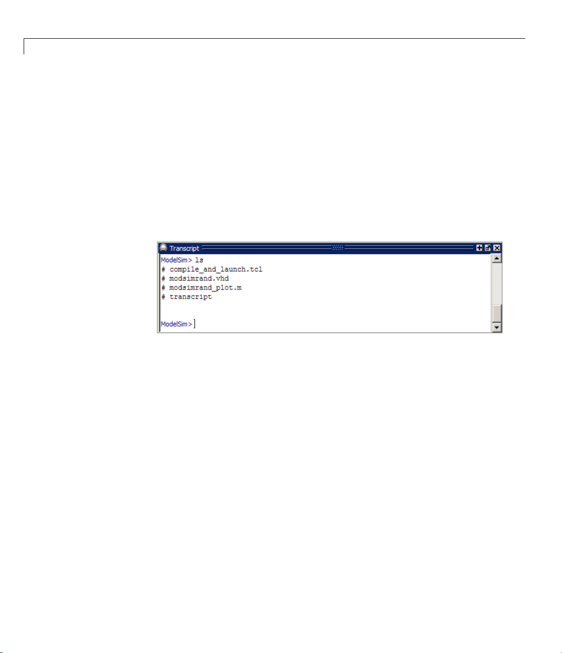
1 Simulating an HDL Component in a MATLAB
1 Start ModelSim from the MATLAB environment by calling the function
vsim in the MATLAB Command Window.
vsim
This function launches and configures ModelSim for use with the EDA
Simulator Link software. The first folder of ModelSim matches your
MATLAB current folder.
2 Verify the current ModelSim folder. You can verify that the current
ModelSim folder matches the MATLAB current folder by entering the
command in the ModelSim command window.
®
Test Bench Environment
ls
1-48
The command shou ld list the files modsimrand.vhd, modsimrand_plot.m,
transcript,andcompile_and_launch.tcl.
If it does not, change your ModelSim folder to the current MATLAB folder.
You can find the current MATLAB folder by looking in the Current Folder
Browser or by viewing the Current folder navigation bar. In ModelSim, you
can change the working folder by issuing the command
cd directory
Where directory is the folder you want to work from. Or you may also
change directory by selecting File > Change Directory....
3 Create a design library to
the library and required
hold your demo compilation results. To create
info
_
file, enter the vlib and vmap commands as
follows:
ModelSim> vlib work
ModelSim> vmap work work
Page 73
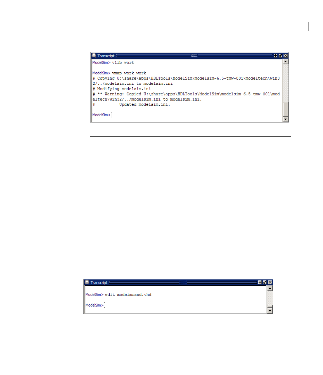
Tutorial – Running a Sample ModelSim and MATLAB®Test Bench Session
Note You must use the ModelSim File menu or vlib command to create
the library folder to ensure that the required
_info file is created. Do not
create the library with operating system commands.
Developing the VHDL Code
After setting up a design library, typically you would use the ModelSim Editor
to create and modify your HDL code. For this tutorial, you do not need to
create the VHDL code yourself. Instead, open and examine the existing file
modsimrand.vhd. This section highlights areas of code in modsimrand.vhd
that are of interest for a ModelSim and MATLAB test bench.
If you choose not to examine the H DL code at this time, skip to “Compiling
the VHDL File” on page 1-51.
You can open
modsimrand.vhd in the edit window with the edit command, as
follows:
ModelSim> edit modsimrand.vhd
1-49
Page 74

1 Simulating an HDL Component in a MATLAB
ModelSim opens its edit windo w and displays th e VHDL code for
modsimrand.vhd.
®
Test Bench Environment
1-50
While you are viewing the file, note the following:
• The line
modsimrand:
ENTITY modsimrand contains the definition for the VHDL entity
ENTITY modsimrand IS
PORT (
clk : IN std_logic ;
clk_en : IN std_logic ;
reset : IN std_logic ;
dout : OUT std_logic_vector (31 DOWNTO 0);
END modsimrand;
This is the entity that will be verified in the MATLAB environment during
the tutorial. Note the following:
Page 75

Tutorial – Running a Sample ModelSim and MATLAB®Test Bench Session
- Bydefault,theMATLABserverassumesthatthenameoftheMATLAB
function that verifies the entity in the MATLAB environment is the
same as the entity name. You have the option of naming the MATLAB
function explicitly. However, if you do not specify a name, the server
expects the function name to match the entity name. In this example,
the MATLAB function name is
modsimrand_plot and does not match.
- The entity must be defined with a PORT clause that includes at least one
port definition. Each port definition must specify a port mode (
INOUT)andaVHDLdatatypethatissupportedbytheEDASimulator
Link softw are. For a list of the supported types, see “Code HDL Modules
for Verification Using MATLAB ” on page 1-7.
IN, OUT,or
The entity
ports
of type STD_LOGIC_VECTOR. The output port passes simulation output
data out to the MATLAB function for verification. The optional input
ports receive clock and reset signals from the function. Alternatively, the
input ports can receive signals from ModelSim
For more information on coding port entities for use with MATLAB, see
“Code HD L Modules f or Verification Using MATLAB ” on page 1-7.
• The remaining code for
for
modsimrand that writes a randomly generated Fibonacci sequence to an
output register when the clock experiences a rising edge.
When you are finished examining the file, close the ModelSim edit window.
modsimrand in this example is defined with three input
clk, clk_en,andreset of type STD_LOGIC and output port dout
force commands.
modsimrand.vhd defines a behavioral architecture
Compiling the VHDL File
AfteryoucreateoredityourVHDLsourcefiles, compile them. As part of this
tutorial, compile
file name in the project workspace and select Compile > Compile All.An
alternativeistospecify
ModelSim> vcom modsimrand.vhd
If the compilation succeeds, messages appear in the command window and
the compiler populates the work library with the compilation results.
modsimrand.vhd. Onewayofcompilingthefileistoclickthe
modsimrand.vhd with the vcom command, as follows:
1-51
Page 76

1 Simulating an HDL Component in a MATLAB
Developing the MATLAB Function
The EDA Simulator Link software verifies HDL hardware in MATLAB as a
function. Typically, at this point you would create or edit a MATLAB function
that meets EDA Simulator Link requirements. For this tutorial, you do not
need to develop the MATLAB test bench function yourself. Instead, open and
examine the existing file
If you choose not to examine the HDL code a t this time, skip to “Loading
the Simulation” on page 1-54.
®
Test Bench Environment
modsimrand_plot.m.
1-52
Note modsimrand_plot.m is a lower-level component of the MATLAB
Random Number Generator Demo. Plotting code within
modsimrand_plot.m
is not discussed in the next section. This tutorial focuses only on those parts of
modsimrand_plot.m that are required for MATLAB to verify a VHDL model.
You can open modsimrand_plot.m in the MATLAB Edit/Debug window. For
example:
edit modsimrand_plot.m
While you are viewing the file, note the following:
• On line 1, you will find the MATLAB function name specified along with its
required parameters:
function [iport,tnext] = modsimrand_plot(oport,tnow,portinfo)
Page 77

Tutorial – Running a Sample ModelSim and MATLAB®Test Bench Session
This function definition is significant because it represents the
communication channel between MATLAB and ModelSim. Note:
- W hen coding the function, you must define the function with two output
parameters,
and
portinfo. S ee “Defining EDA Simulator Link MATLAB Functions
and Function Parameters” on page 7-42.
iport and tnext, and three input parameters, oport, tnow,
- You can use the iport parameter to drive input signals instead
of, or in addition to, using other signal sources, such as ModelSim
force commands. Depending on your application, you might use any
combination of input sources. However, if multiple sources drive signals
to a single
contention.
• On lines 22 and 23, you will find some parameter initialization:
tnext = [];
iport = struct();
In this case, function outputs iport and tnext are initialized to empty
values.
iport, you will need a resolution function to handle signal
• When coding a MATLAB function for use with EDA Simulator Link, you
need to know the types of the data that the test bench function receives from
and needs to return to ModelSim and how EDA Simulator Link handles
this data; see “Performing Data TypeConversions”onpage7-5. This
function includes the following port data type definitions and conversions:
- The entity defined for this tutorial consists of three input ports of type
STD_LOGIC and an output port of type STD_LOGIC_VECTOR.
- D ata of type STD_LOGIC_VECTOR consists of a column vector of characters
with one b it per character.
- T he interface converts scalar data of type STD_LOGIC to a character that
matches the character literal for the corresponding enumerated type.
On line 62, the line of code containing
a MATLAB function receives from ModelSim might need to be converted
for use in the MATLAB environment:
ud.buffer(cyc) = mvl2dec(oport.dout)
oport.dout show s how the data that
1-53
Page 78

1 Simulating an HDL Component in a MATLAB
In this case, the function receives STD_LOGIC_VECTOR data on oport.The
function
in arithmetic computations. “Performing Data Type Conversions” on page
7-5 provides a summary of the types of data co nversions to consider when
coding your own MATLAB functions.
mvl2dec converts the bit vector to a decimal value that can be used
®
Test Bench Environment
• Feel free to browse through the rest of
modsimrand_plot.m.Whenyouare
finished, go to “Loading the Simulation” on page 1-54.
Loading the Simulation
After you successfully compile the VHDL source file, you are ready to load the
model for simulation. This section explains how to load an instance of entity
modsimrand for simulation:
1 Loadtheinstanceofmodsimrand for verification. To load the instance,
specify the
ModelSim> vsimmatlab modsimrand
The vsimmatlab command starts the ModelSim simulator, vsim,
specifically for use with MATLAB. ModelSim displays a series of messages
in the command window as it loads the entity’s packages and architecture.
vsimmatlab command as follows:
1-54
Page 79

Tutorial – Running a Sample ModelSim and MATLAB®Test Bench Session
2 Initialize the simulator for verifying modsimrand with MATLAB. You
initialize ModelSim by using the EDA Simulator Link
matlabtb command.
This command defines the communication link and a callback to a
MATLAB function that executes in MATLAB on behalf of ModelSim. In
addition, the
matlabtb command can specify parameters that control when
the MATLAB function executes.
For this tutoria l, enter the following
matlabtb command:
1-55
Page 80

1 Simulating an HDL Component in a MATLAB
VSIM n> matlabtb modsimrand -mfunc modsimrand_plot -rising
/modsimrand/clk -socket portnum
Arguments in the command line specify the following conditions:
modsimrand—SpecifiestheVHDLmoduletocosimulate.
•
-mfunc modsimrand_plot—Links an instance of the entity modsimrand
•
to the MATLAB function modsimrand_plot.m. The argument is required
because the entity name is not the same as the test bench function name.
•
-rising /modsimrand/clk—Specifies that the test bench function be
called wh enever signal
-socketportnum—Specifies the port number issued w ith or returned by
•
the call to
3 Initialize clock and reset input signals. You can drive simulation input
signals using several mechanisms, including ModelSim
and an
1-15). For now, enter the following
iport parameter (see “Syntax of a Test Bench Function” on page
®
Test Bench Environment
/modsimrand/clk experiences a rising edge.
hdldaemon in “Starting the MATLAB Server” on page 1-46.
force commands
force commands:
1-56
VSIM n> force /modsimrand/clk 0 0 ns, 1 5 ns -repeat 10 ns
n> force /modsimrand/clk_en 1
VSIM
n> force /modsimrand/reset 1 0, 0 50 ns
VSIM
The first command forces the clk signal to value 0 at 0 nanoseconds and to
1 at 5 nanoseconds. After 10 nanoseconds, the cycle starts to repeat every
10 nanoseconds. The second and third
and
reset to 1 at 0 nanoseconds and to 0 at 50 nanoseconds.
force commands set clk_en to 1
The ModelSim environment is ready to run a simulation. Now, you need to
set up the MATLAB function.
Running the Simulation
This section explains how to start a n d monitor this simulation, and rerun it, if
necessary. When you have completed as many simulation runs as desired,
shut down the simulation as described in the next section.
Page 81

Tutorial – Running a Sample ModelSim and MATLAB®Test Bench Session
Running the Simulation for the First Time
Before running the simulation for the first time, you must verify the client
connection. You may also want to set breakpoints for debugging.
Perform the following steps:
1 Open ModelSim and MATLAB windows.
2 In MATLAB, verify the client connection by callin g hdldaemon with the
'status' option:
hdldaemon('status')
This function returns a messa
HDLDaemon socket server is running on port 4795 with 1 connection
ge indicating a connection exists:
Or
HDLDaemon shared memory server is running with 1 connection
Note If you attempt to run the simulation before starting the hdldaemon
in MATLAB, you will receive the following warning:
#ML Warn - MATLAB server not available (yet),
The entity 'modsimrand' will not be active
3 Open modsimrand_plot.m in the MATLAB Edit/Debug window .
4 Search for oport.dout andsetabreakpointatthatlinebyclickingnextto
the line number. A red breakpoint marker will appear.
5 Return to ModelSim and enter the following command in the command
window:
VSIM n> run 80000
This com m and instructs ModelSim to advance the simulation 80,000 time
steps (80,000 nanoseconds using the default time step period). Because
1-57
Page 82
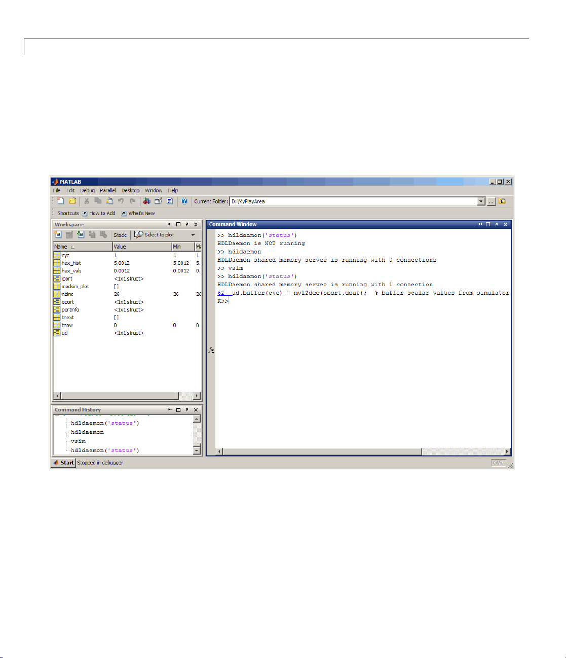
1 Simulating an HDL Component in a MATLAB
you previously set a breakpoint in modsimrand_plot.m, however, the
simulation runs in MATLAB until it reaches the breakpoint.
ModelSim is now blocked and remains blocked until you explicitly unblock
it. While the simu lation is blocked, note that MATL A B displays the data
that ModelSim passed to the MATLAB function in the Workspace window.
®
Test Bench Environment
1-58
In ModelSim, an empty figure window opens. You can use this window to
plot data generated by the simulation.
6 Examine oport, portinfo,andtnow by hovering over these arguments
inside the MATLAB Editor. Observe that
time, is set to
0. Also notice that, because the simulation has reached
a breakpoint during the first call to
tnow, the current simulation
modsimrand_plot,theportinfo
argument is visible in the MATLAB workspace.
Page 83

Tutorial – Running a Sample ModelSim and MATLAB®Test Bench Session
7 Click Debug > Continue in the MATLAB Edit/Debug window. The next
time the breakpoint is reached, notice that
the M ATLA B workspace. The
portinfo function does not show because it
portinfo no longer appears in
is passed in only on the first function invocation. Also note that the value
of
tnow advances from 0 to 5e-009.
8 Clear the breakpoint by clicking the red breakpoint marker.
9 Unblock ModelSim and continue the simulation by clicking
Debug > Continue in the MATLAB Edit/Debug w indow.
The simulation runs to completion. As the simulation progresses, it plots
generated data in a figure window. When the simulation completes, the
figure window appears as shown here.
1-59
Page 84
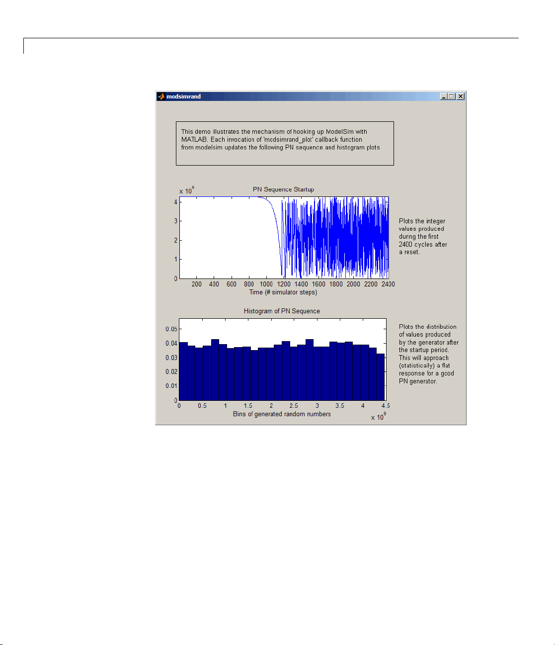
1 Simulating an HDL Component in a MATLAB
®
Test Bench Environment
1-60
The simulation runs in M ATLAB until it reaches the breakpoint that you just
set. Continue the simulation/debugging session as desired.
Rerunning the Simulation
If you want to run the simulation again, you must restart the simulation in
ModelSim, reinitialize the clock, and reset input signals. To do so:
1 Close the figure window.
2 Restart the simulation with the following command:
Page 85

Tutorial – Running a Sample ModelSim and MATLAB®Test Bench Session
VSIM n> restart
The Restart dialog box appears. Leave all the options enabled, and click
Restart.
Note The Restart button clears the simulation context established by a
matlabtb command. Thus, after restarting ModelSim, you must reissue
the previous command or issue a new command.
3 Reissue the matlabtb command.
VSIM n> matlabtb modsimrand -mfunc modsimrand_plot -rising
/modsimrand/clk -socket
4 Open modsimrand_plot.m in the MATLAB Edit/Debug window .
5 Set a breakpoint at the same line as in the previous run.
portnum
6 Return to ModelSim and re-enter the following commands to reinitialize
clock and input signals:
VSIM n> force /modsimrand/clk 0 0,1 5 ns -repeat 10 ns
VSIM
VSIM
7 Enter a command to start the simulation, for example:
n> force /modsimrand/clk_en 1
n> force /modsimrand/reset 1 0, 0 50 ns
VSIM n> run 80000
Shutting Down the Simulation
This section explains how to shut downasimulationinanorderlyway.
In ModelSim, perform the following steps:
1 Stop the simulation on the client side by selecting Simulate > End
Simulation or entering the
2 Quit ModelSim.
quit command.
1-61
Page 86

1 Simulating an HDL Component in a MATLAB
In MATLAB, you can just quit the application, which will shut down the
simulation and also close MATLAB.
To shut down the server without closing MATLAB, you have the option of
calling
The following message appears, confirming that the server was shut down:
hdldaemon with the 'kill' option:
hdldaemon('kill')
HDLDaemon server was shutdown
®
Test Bench Environment
1-62
Page 87

2
Replacing an HDL Component with a MATLAB Component Function
• “Overview to Using a MATLAB Function as a Component” on page 2-2
• “Code HDL Modules for Visualization Using MAT LAB” on page 2-7
• “Create an EDA Simulator Link MATLAB Component Function” on page
2-13
• “Place Component Function on MATLAB Search Path” on page 2-15
• “Start Connection to HDL Simulator for Component Function Session”
on page 2-16
• “Launch HDL Simulator for Use with MATLAB Component Session” on
page 2-18
• “Invoke matlabcp to Bind M ATLAB Component Function Calls” on page
2-20
• “Schedule Options for a Component Session” on page 2-25
• “Run MATLAB Component Function Simulation” on page 2-29
• “Stop Component Simulation” on page 2-38
Page 88

2 Replacing an HDL Component with a MATLAB
®
Component Function
Overview to Using a MATLAB Function as a Component
In this section...
“How MATLAB and the HDL Simulator Communicate During a Component
Session” on page 2-2
“Workflow for Creating a MATLAB Component Function for Use with the
HDL Simulator” on page 2-4
How MATLAB and the HDL Simulator Communicate
During a Component Session
The EDA Simulator Link software provides a means for visua l izi n g HDL
components w ithin the MATLAB environment. You do so by coding an HDL
model and a MATLAB function that can share data with the HDL model. This
chapter discusses the program ming, interfacing, and scheduling conventions
for MATLAB component functions that communicate with the HDL simulator.
2-2
MATLAB component functions simulate the behavior of components in the
HDL model. A stub module (providing port definitions only) in the HDL model
passes its input s ignals to the MATLAB component function. The MATLAB
component processes this data and returns the results to the outputs of the
stub module. A MATLAB component typically provides some functionality
(such as a filter) that is not yet implemented in the HDL code.
The follow i ng figure sho ws how an HDL simulator wraps around a MATLAB
component function and how MATLAB communicates with the HDL
simulator during a component simulation session.
Page 89
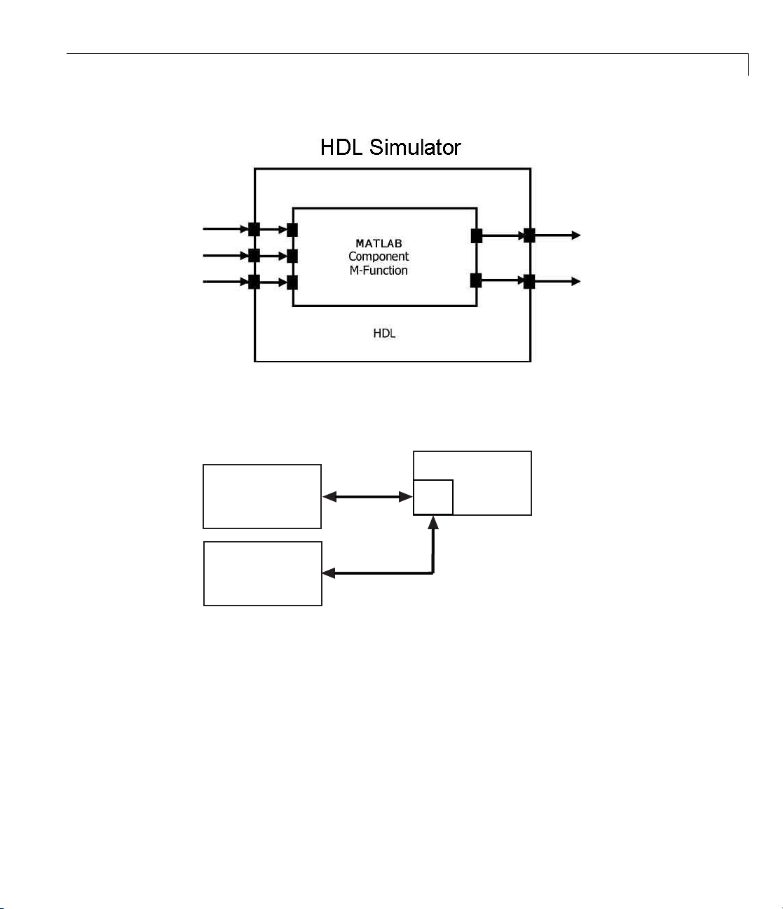
Overview to Using a MATLAB Function as a Component
When linked with MATLAB, the HDL simulator functions as the client, with
MATLAB as the server. The following figure shows a multiple-client scenario
connecting to the server at TCP/IP socket port 4449.
HDL Simulator
Client
HDL Simulator
Client
Link
Port
4449
Link
MATLAB
Server
TheMATLABservercanservicemultiple simultaneous HDL simulator
sessions and HDL modules. How eve r, you should follow recommended
guidelines to ensure the server can track the I/O associated with each
module and session. The MATLAB server, which you start with the supplied
MATLAB function
hdldaemon, waits for connection requests from instances
of the HDL simulator running on the same or different computers. When
the server receiv es a request, it ex ecutes the specified MATLAB function
you have coded to perform tasks on behalf of a module in your HDL design.
Parameters that you specify when you start the server indicate whether the
server establishes shared memory or TCP/IP socket communication links.
2-3
Page 90

2 Replacing an HDL Component with a MATLAB
Refer to“Establishing EDA Simulator Link Machine Configuration
Requirements” on page 6 -26 for valid machine configurations.
Note The programming, interfacing, and scheduling conventions for test
bench functions and component functions are virtually identical (see Chapter
1, “Simulating an HDL Component in a MATLAB Test Bench Environment”).
For the most part, the same procedures apply to both types of functions.
Workflow for Creating a MATLAB Com ponent
Function for Use with the HDL Simulator
The following workflow shows the steps necessary to create a MATLAB
component function for cosimulation with the HDL simulator using EDA
Simulator Link.
®
Component Function
2-4
Page 91
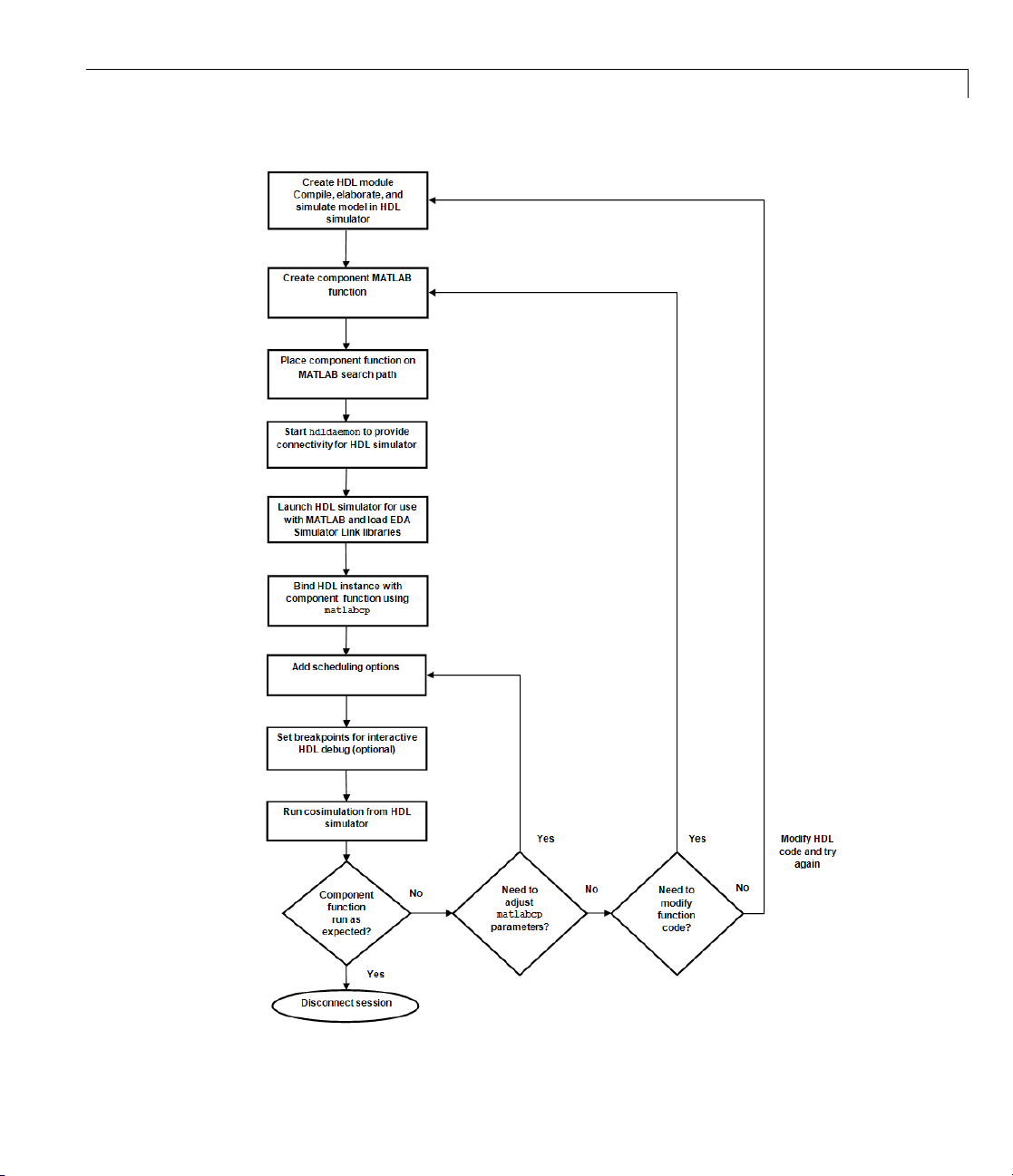
Overview to Using a MATLAB Function as a Component
2-5
Page 92

2 Replacing an HDL Component with a MATLAB
Theworkflowisasfollows:
1 Create HDL module Compile, elaborate, and simulate model in HDL
simulator . See “Code HDL Modules for Visualization Using MATLAB”
on page 2-7.
2 Create component MATLAB function. See “Create an EDA Simulator Link
MATLAB Component Function” on page 2-13.
3 Place component function on MATLAB search path. See “Place Test Bench
Function on MATLAB Search Path” on page 1-21.
4 Start hdldaemon to provide connectivity for HDL simulator. See “Start
ConnectiontoHDLSimulatorforTestBenchSession”onpage1-22.
5 Launch HDL simulator for use with MATLAB and load EDA Simulator
Link libraries. See “Launch HDL Simulator for Use with MATLAB Test
Bench” on page 1-24
6 Bind HDL instance with component function using matlabcp. See “Invoke
matlabtb to Bind MATLAB Test Bench Function Calls” on page 1-26.
®
Component Function
2-6
7 Add scheduling options. See “Schedule Options for a Test Bench Session”
on page 1-31.
8 Set breakpoints for interactive HDL debug (optional).
9 Run cosimulation from HDL simulator. See “Run MATLAB Test Bench
Simulation” on page 1-35.
10 Disconnect session. See “Stop Component Simulation” on page 2-38.
Page 93

Code HDL Modules for Visualization Using MATLAB
Code HDL Modules for Visualization Using MATLAB
In this section...
“Overview to Coding HDL Modules for Visualization with MATLAB” on
page 2-7
“Choosing an HDL Module Name for Use with a MATLAB Component
Function” on page 2-8
“Specifying Port Direction Modes in HDL M odule for Use with Component
Functions” on page 2-8
“Specifying Port Data Types in HDL Modules for Use with Component
Functions” on page 2-8
“Compiling and Elaborating the HDL Design for U se with Component
Functions” on page 2-10
Overview to Coding HDL Modules for Visualization with MATLAB
The most basic element of communication in the EDA Simulator Link
interface is the HDL module. The interface passes all data between the HDL
simulator and MATL AB as port data. The EDA Simulator Link software
works with any existing HDL module. Howeve r, when you code an HDL
module that is targeted for MATLAB verification, you should consider its
name, the types of data to be shared between the two environments, and the
direction modes. The sections within this chapter cover these topics.
The process for coding HDL modules for MATLAB visualization is a s follows:
• Choose an HDL module name.
• Specify port d irection modes in HDL components.
• Specify port data types in HDL components.
• Compile and debug the HDL model.
2-7
Page 94

2 Replacing an HDL Component with a MATLAB
Choosing an HDL Module Name for Use with a
MATLAB Component Function
Although not required, when naming the HDL module, consider choosing a
name that also can be used as a MATLAB function name. (Generally, naming
rules for VHDL or V erilog and MATLAB are compatible.) By default, EDA
Simulator Link software assumes that an HDL module and its simulation
function share the same name. See “Invoke m atlabtb to Bind MATLAB Test
Bench Function Calls” on page 1-26.
For details on MATLAB function-naming guidelines, see “MATLAB
Programming Tips” on files and file names in the MATLAB documentation.
Specifying Port Direction Modes in HDL Module for
Use with Component Functions
In your module statement, you must specify each port with a direction mode
(input, output, or bidirectional). The following table defines these three modes.
®
Component Function
2-8
Use VHDL
Mode...
IN input
OUT output
INOUT inout
Use Verilog
Mode...
For Ports That...
Represent signals that can be driven by a
MATLAB function
Represent signal values that are passed to
a MATLAB function
Represent bidirectional signals that can
be driven by or pass values to a MATLAB
function
Specifying Port Data Types in HDL Modules for Use
with Component Functions
This section describes how to specify data types compatible with MATLAB
for ports in your HDL modules. For details on how the EDA Simulator Link
interface converts data types for the MATLAB environment, see “Performing
Data Type Conversions” on page 7-5.
Page 95

Code HDL Modules for Visualization Using MATLAB
Note If you use unsupported types, the EDA Simulator Link software issues
a warning and ignores the port at run time. For example, if you define your
interface with f ive ports, one of which is a VHDL access port, at run time,
then the interface displays a warning and your code sees only four ports.
Port Data Types for VHDL Entities
In your entity statement, you must define each port that you plan to test with
MATLAB with a VHDL data type that is supported by the EDA Simulator
Link software. The interface can convert scalar and array data of the
following VHDL types to comparable MATLAB types:
•
STD_LOGIC, STD_ULOGIC, BIT, STD_LOGIC_VECTOR, STD_ULOGIC_VECTOR,
and
BIT_VECTOR
• INTEGER and NATURAL
• REAL
• TIME
• Enumerated types, including user-defined enumerated types and
CHARACTER
The interface also supports all subtypes and arrays of the preceding types.
Note The EDA Simulator Link software does not support VHDL extended
identifiers for the following components:
• Port and signal names used in cosimulation
• Enum literals when used as array indices of port and signal names used
in cosimulation
However, the software does support basic identifiers for VHDL.
2-9
Page 96

2 Replacing an HDL Component with a MATLAB
Port Data Types for Verilog Modules
In your modu le definition, you must defin e each port that you plan to t e s t
with MATLAB with a Verilog port data type that is supported by the EDA
Simulator Link software. The interface can convert data of the following
Verilog port types to comparable MATLAB types:
• reg
• integer
• wire
Note EDA Simulator Link software does not support Verilog escaped
identifiers for port and signal names used in cosimulation. However, it does
support simple identifiers for Verilog.
Compiling and Elaborating the HDL Design for Use
with Component Functions
After you create or edit your HDL source files, use the HDL simulator
compiler to compile and debug the code.
®
Component Function
2-10
Compilation for ModelSim
You have the option of invoking the compiler from menus in the ModelSim
graphic interface or from the command line with the
following sequence of ModelSim commands creates and maps the design
library
The following sequence of ModelSim commands crea t es and maps the design
library
work and compiles the VHDL file modsimrand.vhd:
ModelSim> vlib work
ModelSim> vmap work work
ModelSim> vcom modsimrand.vhd
work and compiles the Verilog file test.v:
ModelSim> vlib work
ModelSim> vmap work work
ModelSim> vlog test.v
vcom command. The
Page 97

Code HDL Modules for Visualization Using MATLAB
Note You should provide read/write access to the signals that are connecting
to the MATLAB session for cosimulation. For higher performance, you
want to provide access only to those signals used in cosimulation. You can
check read/write access through the HDL simulator—see HDL simulator
documentation for details.
Compilation for Incisive
The Cadence Incisive simulator allows for 1-step and 3-step processes for HDL
compilation, elaboration, and simulation. The following Cadence Incisive
simulator command compiles the Verilog file test.v:
sh> ncvlog test.v
The following Cadence Incisive simulator command compiles and elaborates
the Verilog design
test.v, and then loads it for si mulation, in a single step:
sh> ncverilog +gui +access+rwc +linedebug test.v
The following sequence of Cadence Incisive simulator commands performs all
thesameprocessesinmultiplesteps:
sh> ncvlog -linedebug test.v
sh> ncelab -access +rwc test
sh> ncsim test
Note You should provide read/write access to the signals that are connecting
to the MATLAB session for cosimulation. The previous example shows
how to provide read/write access to all signals in your design. For higher
performance, you want to provide access only to those signals used in
cosimulation. See the description of the
-access argument to ncelab for details.
+access flag to ncverilog and the
2-11
Page 98

2 Replacing an HDL Component with a MATLAB
Compilation for Discovery
Compilation of source files for use with MATLAB and Discovery is most
easily accomplished using the scripts automatically generated by the EDA
Simulator Link HDL simulator launch command
Examples section of the reference page for
Note You should provide read/write access to the signals that are connecting
to the MATLAB session for cosimulation. For higher performance, you want to
provide access only to those signals used in cosimulation. A tab file is included
in the simulation via the required
For more examples, see the EDA Simulator Link tutorialsanddemos. For
details on using the HDL compiler, see the simulator documentation.
®
Component Function
launchDiscovery.Seethe
launchDiscovery.
launchDiscovery property "AccFile".
2-12
Page 99

Create an EDA Simulator Link™ MATLAB®Component Function
Create an EDA Simulator Link MATLAB Component Function
In this section...
“Overview to Coding an EDA Simulator Link Component Function” on
page 2-13
“Syntax of a Component F unction” on page 2-14
Overview to Coding an EDA Simulator Link Component Function
Coding a MATLAB function that is to visualize an HDL module or component
requires that you follow specific coding conventions. You must also
understand the data type conversions that occur, and program data type
conversions for operating on data and returning data to the HDL simulator.
To code a MATLAB function that is to verify an HDL module or component,
perform the following steps:
1 Learn the syntax for a MATLAB EDA S imulator Link component function
(see “Syntax of a Component Function” o n page 2-14.).
2 Understand how E DA Simulator Link software converts data from the
HDL simulator for use in the MATLAB environment (see “Performing Data
Type Conversions” on page 7-5).
3 Choos
4 Define expected parameters in the component function definition line
5 Determine the types of port data being passed into the function (see
6 Ext
e a name for the MATLAB component function (see “Invoke matlabcp
d M AT LAB Component Function Calls” on page 2-20).
to Bin
(see “Defining EDA Simulator Link MATLAB Functions and Function
Parameters” on page 7-42).
“Defining EDA Simulator Link MATLAB Functions and Function
Parameters” on page 7-42).
ract and, if appropriate for the simulation, apply information received
the
in
In
portinfo structure (see “Gaining Access to and Applying Port
formation” on page 7-45).
2-13
Page 100

2 Replacing an HDL Component with a MATLAB
7 Convert data for manipulation in the MATLAB environment, as necessary
(see “Converting HDL Data to Send to MATLAB” on page 7-5).
8 Convert data that needs to be returned to the HDL simulator (see
“Converting Data for Return to th e HDL Simulator” on page 7-10).
Syntax of a Com ponent Function
The syntax of a MATLAB component function is
function [iport, tnext] = MyFunctionName(oport, tnow, portinfo)
The input/output arguments (iport and oport) for a MATLAB component
function are the reverse of the port arguments for a MATLAB test bench
function. That is, the MATLAB component function returns signal data to the
outputs and receives data from the inputs of the associated HDL module.
Initialize the function outputs to empty values at the beginning of the function
as in the following example:
®
Component Function
2-14
tnext = [];
oport = struct();
See the “Defining EDA Simulator Link MATLAB Functions and Function
Parameters” on page 7-42 for an explanation of each of the function
arguments. For more information on using
scheduling with
matlabcp, see “Scheduling C omponent Functions Using the
tnext and tnow for simulation
tnext Parameter” on page 2-26.
 Loading...