

Page 1

Data Acquisition Toolbox™ Adaptor Kit
User’s Guide
2
Page 2

How to Contact The MathWorks
www.mathworks.c
comp.soft-sys.matlab Newsgroup
www.mathworks.com/contact_TS.html Technical Support
suggest@mathworks.com Product enhancement suggestions
bugs@mathworks.c
doc@mathworks.com Documentation error reports
service@mathworks.com Order status, license renewals, passcodes
info@mathworks.c
om
om
om
Web
Bug reports
Sales, pricing, an
d general information
508-647-7000 (Phone)
508-647-7001 (Fax)
The MathWorks, Inc.
3 Apple Hill Drive
Natick, MA 01760-2098
For contact information about worldwide offices, see the MathWorks Web site.
Data Aquisition Toolbox™ Adaptor Kit User's Guide
© COPYRIG HT 2
The software described in this document is furnished under a license agreement. The software may be used
or copied only under the terms of the license agreement. No part of this manual may be photocopied or
reproduced in any form without prior written consent fr om The MathWorks, Inc.
FEDERAL ACQUISITION: This provision applies to all acquisitions of the Program and Documentation
by, for, or through the federal government of the United States. By accepting delivery of the Program or
Documentation, the government hereby agrees that this software or documentation qualifies as commercial
computer software or commercial computer software documentation as such terms are used or defined
in FAR 12.212, DFARS Part 227.72, and DFARS 252.227-7014. Accordingly, the terms and conditions of
this Agreement and only those right s specified in this Agreement, shall pertain to and govern the use,
modification, reproduction, release, performance, display, and disclosure of the Program and Documentation
by the federal government (or other entity acquiring for or through the federal government) and s hall
supersede any conflicting contractual terms or conditions. If this License fails to meet the government’s
needs or is inconsistent in any respect with federal procurement law, the government agrees to return the
Program and Documentation, unused, to The MathWorks, Inc.
Trademarks
MATLAB and Simulink are registered trademarks of The MathWorks, Inc. See
www.mathworks.com/trademarks for a list of additional trademarks. Other product or brand
names may be trademarks or registered trademarks of their respective holders.
Patents
The MathWorks products are protected by one or more U.S. patents. Please see
www.mathworks.com/patents for more information.
000–2010 by The MathWorks, Inc.
Page 3

Revision History
November 2000 Online only New for Version 1 (Release 12)
July 2002 Online only Revised for Version 2 (Release 13)
June 2004 Online only Minor revision for Version 2.5 (Release 14)
September 2005 Online only Minor revision for Version 2.7 (Release 14SP3)
March 2006 Online only Minor revision for Version 2.9 (Release 2006a)
March 2008 Online only Minor revision for Version 2.12 (Release 2008a)
October 2008 Online only Minor revision for Version 2.13 (Release 2008b)
March 2010 Online only Minor revision for Version 2.16 (Release 2010a)
Page 4

Page 5

Introduction
1
Overview . . . . . . . . . . . . . . . . . . . . . . . . . . . . . . . . . . . . . . . . . . . . 1-2
Who Should Read This Document? . . . . . . . . . . . . . . . . . . . . . . 1-2
What Knowledge Is Required? . . . . . . . . . . . . . . . . . . . . . . . . . . 1-2
What Effort Is Required? . . . . . . . . . . . . . . . . . . . . . . . . . . . . . . 1-2
Tools . . . . . . . . . . . . . . . . . . . . . . . . . . . . . . . . . . . . . . . . . . . . . . . 1-3
Writing an Adaptor Versus Writing a MEX File . . . . . . . . . . 1-4
What Is the Adaptor Kit? . . . . . . . . . . . . . . . . . . . . . . . . . . . . . . 1-6
Toolbox Architecture . . . . . . . . . . . . . . . . . . . . . . . . . . . . . . . . . 1-9
Using This Manual . . . . . . . . . . . . . . . . . . . . . . . . . . . . . . . . . . . 1-11
Contents
2
Overview . . . . . . . . . . . . . . . . . . . . . . . . . . . . . . . . . . . . . . . . . . . . 2-2
A Basic View of Toolbox-Engine-Adaptor Relationships . . . . . . 2-2
Example: an Analog Input Session . . . . . . . . . . . . . . . . . . . . . . 2-3
Example: an Analog Output Session . . . . . . . . . . . . . . . . . . . . 2-8
Example: a Digital I/O Session . . . . . . . . . . . . . . . . . . . . . . . . 2-10
Tutorial
i
Page 6

Step-by-Step Instructions for Adaptor Creation
3
Overview: Building the Adaptor . . . . . . . . . . . . . . . . . . . . . . . . 3-2
Toolbox Adaptors . . . . . . . . . . . . . . . . . . . . . . . . . . . . . . . . . . . . . 3-3
The winsound Adaptor . . . . . . . . . . . . . . . . . . . . . . . . . . . . . . . . . 3-3
The mcc Adaptor . . . . . . . . . . . . . . . . . . . . . . . . . . . . . . . . . . . . . . 3-3
The nidaq Adaptor . . . . . . . . . . . . . . . . . . . . . . . . . . . . . . . . . . . . 3-4
The hpe1432 Adaptor . . . . . . . . . . . . . . . . . . . . . . . . . . . . . . . . . . 3-5
The keithley Adaptor . . . . . . . . . . . . . . . . . . . . . . . . . . . . . . . . . . 3-5
About the Demo Adaptor Software . . . . . . . . . . . . . . . . . . . . . . 3-7
Features . . . . . . . . . . . . . . . . . . . . . . . . . . . . . . . . . . . . . . . . . . . . 3-7
Limitations . . . . . . . . . . . . . . . . . . . . . . . . . . . . . . . . . . . . . . . . . . 3-7
Modifying the Demo Adaptor . . . . . . . . . . . . . . . . . . . . . . . . . . . 3-7
Stage 1 Select Supported Features . . . . . . . . . . . . . . . . . . . . . . 3-9
Limitations of Software-Clocked Adaptors . . . . . . . . . . . . . . . . 3-11
Stage 2 Create the Adaptor Project and Adaptor Class . . 3-12
Step 2.1 Adaptor and Project Naming . . . . . . . . . . . . . . . . . . . 3-12
Step 2.2 Add Include, Link, and MIDL Directories to
Your Project . . . . . . . . . . . . . . . . . . . . . . . . . . . . . . . . . . . .
Step 2.3 Define Adaptor Classes in the IDL File . . . . . . . . . . 3-14
Step 2.4 Add the Demo Adaptor Class Code . . . . . . . . . . . . . . 3-14
Step 2.5 Modify the Adaptor Class AdaptorInfo() Method . . . 3-16
3-13
ii Contents
Stage 3 Implement the Analog Input Subsystem . . . . . . . .3-18
Step 3.1 Select Property Values, Ranges, and Defaults for
Analog Input . . . . . . . . . . . . . . . . . . . . . . . . . . . . . . . . . . . .
Step 3.2 Add the Demo Analog Input Code to Your Project . . 3-22
Step 3.3 Modify the OpenDevice Method of the Adaptor Class 3-24
Step 3.4 Modify the Analog Input Open and
SetDaqHwInfo Methods . . . . . . . . . . . . . . . . . . . . . . . . . . .
Step 3.5 Implement the SetProperty and
SetChannelProperty Methods . . . . . . . . . . . . . . . . . . . . . .
Step 3.6 Implement the ChildChange Method . . . . . . . . . . . . 3-33
Step 3.7 Implement the GetSingleValue Method . . . . . . . . . . 3-35
Step 3.8 Implement the GetSingleValues Method . . . . . . . . . 3-37
3-19
3-24
3-29
Page 7

Step 3.9 Implement the Start, Trigger, and Stop Methods . . 3-38
Returning Errors from Your Adaptor . . . . . . . . . . . . . . . . . . . . 3-45
Stage 4 Implement the Analog Output Subsystem . . . . . . . 3-46
Step 4.1 Select Property Values, Ranges, and Defaults for
Analog Output . . . . . . . . . . . . . . . . . . . . . . . . . . . . . . . . . .
3-47
Step 4.2 Add the Demo Analog Output Code to Your Project . 3-48
Step 4.3 Modify the OpenDevice Method of the Adaptor Class 3-48
Step 4.4 Modify the Analog Output Open and
SetDaqHwInfo Methods . . . . . . . . . . . . . . . . . . . . . . . . . . .
3-48
Step 4.5 Implement the SetProperty and
SetChannelProperty Methods . . . . . . . . . . . . . . . . . . . . . .
3-49
Step 4.6 Implement the ChildChange Method . . . . . . . . . . . . 3-49
Step 4.7 Implement the PutSingleValue Method . . . . . . . . . . 3-49
Step 4.8 Implement the PutSingleValues Method . . . . . . . . . 3-50
Step 4.9 Implement the Start, Trigger, and Stop Methods . . 3-51
Stage 5 Implement the Digital I/O Subsystem . . . . . . . . . . . 3-54
Step 5.1 Select Property Values, Ranges, and
Defaults for Digital I/O . . . . . . . . . . . . . . . . . . . . . . . . . . .
3-55
Step 5.2 Add the Digital I/O Code from an Adaptor to
Your Project . . . . . . . . . . . . . . . . . . . . . . . . . . . . . . . . . . . .
3-55
Step 5.3 Modify the OpenDevice Method of the Adaptor Class 3-56
Step 5.4 Modify the DigitalIO Open and
SetDaqHwInfo Methods . . . . . . . . . . . . . . . . . . . . . . . . . . .
3-57
Step 5.5 Modify the SetPortDirection Method . . . . . . . . . . . . . 3-57
Step 5.6 Implement the ReadValues Method . . . . . . . . . . . . . 3-58
Step 5.7 Implement the WriteValues Method . . . . . . . . . . . . . 3-59
iii
Page 8

Working with Properties
4
Overview . . . . . . . . . . . . . . . . . . . . . . . . . . . . . . . . . . . . . . . . . . . . . 4-2
Accessing Properties from Your Adaptor . . . . . . . . . . . . . . . . 4-4
Accessing a Property Using GetProperty . . . . . . . . . . . . . . . . . . 4-4
Attaching to a Property . . . . . . . . . . . . . . . . . . . . . . . . . . . . . . . . 4-5
Creating Adaptor-Specific Properties . . . . . . . . . . . . . . . . . . . 4-8
Modifying Property Values, Defaults, and Ranges . . . . . . . 4-10
Setting a Range to Infinity . . . . . . . . . . . . . . . . . . . . . . . . . . . . 4-11
Working with Enumerated Properties . . . . . . . . . . . . . . . . . 4-12
Passing Arrays to MATLAB Using Safe Arrays . . . . . . . . . . 4-14
Buffering Techniques
iv Contents
5
Overview . . . . . . . . . . . . . . . . . . . . . . . . . . . . . . . . . . . . . . . . . . . . . 5-2
Understanding Engine Buffers . . . . . . . . . . . . . . . . . . . . . . . . . 5-3
Implementing Buffering in Your Adaptor . . . . . . . . . . . . . . . 5-6
Direct Buffering . . . . . . . . . . . . . . . . . . . . . . . . . . . . . . . . . . . . . . 5-6
Intermediate Buffering . . . . . . . . . . . . . . . . . . . . . . . . . . . . . . . . 5-9
Page 9

6
A
Callbacks and Threading
Overview . . . . . . . . . . . . . . . . . . . . . . . . . . . . . . . . . . . . . . . . . . . . . 6-2
Monitoring Progress of Acquisition Tasks . . . . . . . . . . . . . . . 6-3
Event Messaging from Device Drivers . . . . . . . . . . . . . . . . . . . . 6-3
Polling the Driver for Acquisition Status . . . . . . . . . . . . . . . . . . 6-4
Threading Your Adaptor’s Task Monitoring Methods . . . . . 6-6
Implementing Callbacks in a Separate Thread . . . . . . . . . . . . . 6-6
Implementing Event Messaging in a Separate Thread . . . . . . . 6-7
Implementing Polling in a Separate Thread . . . . . . . . . . . . . . . 6-8
Adaptor Kit Interface Reference
Overview . . . . . . . . . . . . . . . . . . . . . . . . . . . . . . . . . . . . . . . . . . . . . A-2
ImwDevice . . . . . . . . . . . . . . . . . . . . . . . . . . . . . . . . . . . . . . . . . . . A-3
FreeBufferData . . . . . . . . . . . . . . . . . . . . . . . . . . . . . . . . . . . . . . A-4
SetChannelProperty . . . . . . . . . . . . . . . . . . . . . . . . . . . . . . . . . . A-4
SetProperty . . . . . . . . . . . . . . . . . . . . . . . . . . . . . . . . . . . . . . . . . . A-5
Start . . . . . . . . . . . . . . . . . . . . . . . . . . . . . . . . . . . . . . . . . . . . . . . A-6
Stop . . . . . . . . . . . . . . . . . . . . . . . . . . . . . . . . . . . . . . . . . . . . . . . . A-7
GetStatus . . . . . . . . . . . . . . . . . . . . . . . . . . . . . . . . . . . . . . . . . . . A-7
ChildChange . . . . . . . . . . . . . . . . . . . . . . . . . . . . . . . . . . . . . . . . . A-8
ImwAdaptor . . . . . . . . . . . . . . . . . . . . . . . . . . . . . . . . . . . . . . . . . A-10
AdaptorInfo . . . . . . . . . . . . . . . . . . . . . . . . . . . . . . . . . . . . . . . . A-10
OpenDevice . . . . . . . . . . . . . . . . . . . . . . . . . . . . . . . . . . . . . . . . . A-12
TranslateError . . . . . . . . . . . . . . . . . . . . . . . . . . . . . . . . . . . . . . A-14
ImwInput . . . . . . . . . . . . . . . . . . . . . . . . . . . . . . . . . . . . . . . . . . . A-15
GetSingleValues . . . . . . . . . . . . . . . . . . . . . . . . . . . . . . . . . . . . . A-15
PeekData . . . . . . . . . . . . . . . . . . . . . . . . . . . . . . . . . . . . . . . . . . A-15
Trigger . . . . . . . . . . . . . . . . . . . . . . . . . . . . . . . . . . . . . . . . . . . . A-17
v
Page 10

B
ImwOutput . . . . . . . . . . . . . . . . . . . . . . . . . . . . . . . . . . . . . . . . . . A-18
PutSingleValues . . . . . . . . . . . . . . . . . . . . . . . . . . . . . . . . . . . . . A-18
Trigger . . . . . . . . . . . . . . . . . . . . . . . . . . . . . . . . . . . . . . . . . . . . A-18
ImwDIO . . . . . . . . . . . . . . . . . . . . . . . . . . . . . . . . . . . . . . . . . . . . . A-19
ReadValues . . . . . . . . . . . . . . . . . . . . . . . . . . . . . . . . . . . . . . . . . A-19
WriteValues . . . . . . . . . . . . . . . . . . . . . . . . . . . . . . . . . . . . . . . . A-20
SetPortDirections . . . . . . . . . . . . . . . . . . . . . . . . . . . . . . . . . . . . A-21
Engine Interface Reference
IPropRoot . . . . . . . . . . . . . . . . . . . . . . . . . . . . . . . . . . . . . . . . . . . . B-2
GetRange . . . . . . . . . . . . . . . . . . . . . . . . . . . . . . . . . . . . . . . . . . . B-3
SetRange . . . . . . . . . . . . . . . . . . . . . . . . . . . . . . . . . . . . . . . . . . . . B-3
GetType . . . . . . . . . . . . . . . . . . . . . . . . . . . . . . . . . . . . . . . . . . . . B-4
get_DefaultValue . . . . . . . . . . . . . . . . . . . . . . . . . . . . . . . . . . . . . B-5
put_DefaultValue . . . . . . . . . . . . . . . . . . . . . . . . . . . . . . . . . . . . . B-5
get_IsHidden . . . . . . . . . . . . . . . . . . . . . . . . . . . . . . . . . . . . . . . . B-6
put_IsHidden . . . . . . . . . . . . . . . . . . . . . . . . . . . . . . . . . . . . . . . . B-6
get_IsReadonlyRunning . . . . . . . . . . . . . . . . . . . . . . . . . . . . . . . . B-7
put_IsReadonlyRunning . . . . . . . . . . . . . . . . . . . . . . . . . . . . . . . B-8
get_IsReadonly . . . . . . . . . . . . . . . . . . . . . . . . . . . . . . . . . . . . . . . B-9
put_IsReadonly . . . . . . . . . . . . . . . . . . . . . . . . . . . . . . . . . . . . . . B-9
get_User . . . . . . . . . . . . . . . . . . . . . . . . . . . . . . . . . . . . . . . . . . . B-10
put_User . . . . . . . . . . . . . . . . . . . . . . . . . . . . . . . . . . . . . . . . . . . B-11
get_Name . . . . . . . . . . . . . . . . . . . . . . . . . . . . . . . . . . . . . . . . . . B-12
put_Name . . . . . . . . . . . . . . . . . . . . . . . . . . . . . . . . . . . . . . . . . . B-12
IsValidValue . . . . . . . . . . . . . . . . . . . . . . . . . . . . . . . . . . . . . . . . B-13
vi Contents
Page 11

IDaqEngine . . . . . . . . . . . . . . . . . . . . . . . . . . . . . . . . . . . . . . . . . . B-14
DaqEvent . . . . . . . . . . . . . . . . . . . . . . . . . . . . . . . . . . . . . . . . . . B-15
GetBuffer . . . . . . . . . . . . . . . . . . . . . . . . . . . . . . . . . . . . . . . . . . B-16
GetBufferingConfig . . . . . . . . . . . . . . . . . . . . . . . . . . . . . . . . . . B-17
GetTime . . . . . . . . . . . . . . . . . . . . . . . . . . . . . . . . . . . . . . . . . . . B-18
PutBuffer . . . . . . . . . . . . . . . . . . . . . . . . . . . . . . . . . . . . . . . . . . B-19
WarningMessage . . . . . . . . . . . . . . . . . . . . . . . . . . . . . . . . . . . . B-20
PutInputData . . . . . . . . . . . . . . . . . . . . . . . . . . . . . . . . . . . . . . . B-21
GetOutputData . . . . . . . . . . . . . . . . . . . . . . . . . . . . . . . . . . . . . B-22
IDaqEnum . . . . . . . . . . . . . . . . . . . . . . . . . . . . . . . . . . . . . . . . . . . B-23
AddEnumValues . . . . . . . . . . . . . . . . . . . . . . . . . . . . . . . . . . . . B-23
ClearEnumValues . . . . . . . . . . . . . . . . . . . . . . . . . . . . . . . . . . . B-23
RemoveEnumValue . . . . . . . . . . . . . . . . . . . . . . . . . . . . . . . . . . B-24
EnumValues . . . . . . . . . . . . . . . . . . . . . . . . . . . . . . . . . . . . . . . . B-25
IDaqMappedEnum . . . . . . . . . . . . . . . . . . . . . . . . . . . . . . . . . . . B-26
AddMappedEnumValue . . . . . . . . . . . . . . . . . . . . . . . . . . . . . . . B-26
FindString . . . . . . . . . . . . . . . . . . . . . . . . . . . . . . . . . . . . . . . . . B-27
FindValue . . . . . . . . . . . . . . . . . . . . . . . . . . . . . . . . . . . . . . . . . . B-27
IPropValue . . . . . . . . . . . . . . . . . . . . . . . . . . . . . . . . . . . . . . . . . . B-29
get_Value . . . . . . . . . . . . . . . . . . . . . . . . . . . . . . . . . . . . . . . . . . B-29
put_Value . . . . . . . . . . . . . . . . . . . . . . . . . . . . . . . . . . . . . . . . . . B-30
IPropContainer . . . . . . . . . . . . . . . . . . . . . . . . . . . . . . . . . . . . . . B-31
CreateProperty . . . . . . . . . . . . . . . . . . . . . . . . . . . . . . . . . . . . . . B-32
GetMemberInterface . . . . . . . . . . . . . . . . . . . . . . . . . . . . . . . . . B-34
put_MemberValue . . . . . . . . . . . . . . . . . . . . . . . . . . . . . . . . . . . B-36
get_MemberValue . . . . . . . . . . . . . . . . . . . . . . . . . . . . . . . . . . . B-37
IChannel . . . . . . . . . . . . . . . . . . . . . . . . . . . . . . . . . . . . . . . . . . . . B-38
get_PropValue . . . . . . . . . . . . . . . . . . . . . . . . . . . . . . . . . . . . . . B-38
put_PropValue . . . . . . . . . . . . . . . . . . . . . . . . . . . . . . . . . . . . . . B-39
UnitsToBinary . . . . . . . . . . . . . . . . . . . . . . . . . . . . . . . . . . . . . . B-39
BinaryToUnits . . . . . . . . . . . . . . . . . . . . . . . . . . . . . . . . . . . . . . B-40
vii
Page 12

C
D
IChannelList . . . . . . . . . . . . . . . . . . . . . . . . . . . . . . . . . . . . . . . . B-41
GetChannelContainer . . . . . . . . . . . . . . . . . . . . . . . . . . . . . . . . B-41
GetChannelStruct . . . . . . . . . . . . . . . . . . . . . . . . . . . . . . . . . . . B-42
GetNumberOfChannels . . . . . . . . . . . . . . . . . . . . . . . . . . . . . . . B-43
CreateChannel (proposed) . . . . . . . . . . . . . . . . . . . . . . . . . . . . . B-44
DeleteChannel . . . . . . . . . . . . . . . . . . . . . . . . . . . . . . . . . . . . . . B-44
DeleteAllChannels . . . . . . . . . . . . . . . . . . . . . . . . . . . . . . . . . . . B-45
Engine Structures
The BUFFER_ST Structure . . . . . . . . . . . . . . . . . . . . . . . . . . . . C-3
The NESTABLEPROP Structure . . . . . . . . . . . . . . . . . . . . . . . . C-5
Sample Property and daqhwinfo Tables
viii Contents
Table of daqhwinfo Properties . . . . . . . . . . . . . . . . . . . . . . . . . D-3
Adaptor daqhwinfo Table . . . . . . . . . . . . . . . . . . . . . . . . . . . . . . D-3
Analog Input daqhwinfo Table . . . . . . . . . . . . . . . . . . . . . . . . . . D-3
Analog Output daqhwinfo Table . . . . . . . . . . . . . . . . . . . . . . . . . D-5
Digital I/O daqhwinfo Table . . . . . . . . . . . . . . . . . . . . . . . . . . . . D-6
Property Info Tables . . . . . . . . . . . . . . . . . . . . . . . . . . . . . . . . . . D-7
Analog Input Subsystem Properties . . . . . . . . . . . . . . . . . . . . . . D-7
Analog Output Subsystem Properties . . . . . . . . . . . . . . . . . . . . . D-9
Digital I/O Subsystem Properties . . . . . . . . . . . . . . . . . . . . . . . D-10
Page 13

Introduction
Overview . . . . . . . . . . . . . . . . . . . . . 1-2
Who Should Read This Document? . . . . . . . . . . . 1-2
What Knowledge Is Required? . . . . . . . . . . . . . 1-2
What Effort Is Required? . . . . . . . . . . . . . . . 1-2
Tools . . . . . . . . . . . . . . . . . . . . . . . . 1-3
Writing an Adaptor Versus Writing a MEX File . . . . 1-4
What Is the Adaptor Kit? . . . . . . . . . . . . . . 1-6
Toolbox Architecture . . . . . . . . . . . . . . . . 1-9
Using This Manual . . . . . . . . . . . . . . . . . 1-11
1
Page 14

1 Introduction
Overview
Who Should Read This Document?
You should read this document if you want to
• Develop an adaptor to support hardware that is not currently supported by
the Data Acquisition Toolbox
• Add new features to an existing adaptor
The Data Acquisition Toolbox Adaptor Kit addresses the needs of individuals
who want to interface the toolbox to a single board, and manufacturers wanting
to interface the toolbox to a range of hardware. Although this document is
aimed primarily at supporting a single board, hardware manufacturers should
use this document as the basis for developing a multiple-board adaptor,
generalizing the single-board support issues appropriately.
What Knowledge Is Required?
To build an adaptor, you should have a working knowledge of
1-2
• C++, Microsoft’s Component Object Model (COM), and the Active Template
Library (ATL)
• The functionality of your hardware device, and its associated Application
Programming Interface (API)
• Data Acquisition Toolbox concepts, functionality, and terminology as
described in the Data Acquisition Toolbox User’s Guide
What Effort Is Required?
The effort required to produce an adaptor depends on the capabilities of the
hardware device and your acquisition requirements.
The simplest type of adaptor supports only single-sample acquisition or burst
acquisition, and uses software clocking. You can create this type of adaptor by
modifying the demo adaptor.
Page 15

Overview
Note Some hardware does not support single-sample acquisition and, as a
result, it does not support software clocking. In this case, you cannot build this
simple type of adaptor.
The next level of complexity is an adaptor that implements hardware clocking
and buffering, but works only for a limited number of similar hardware devices.
In this case, you can decrease development time by hard-coding some
configuration information or by limiting the hardware features that you use.
For example, you might decide to ignore some triggering functionality.
The greatest level of complexity is an adaptor that provides complete support
to a line of data acquisition devices. To develop an adaptor of this type typically
requires a minimum of four months.
Tools
The example code for the Adaptor Kit was created using Microsoft Visual C++
Version 6, Service Pack 4.
1-3
Page 16

1 Introduction
Writing an Adaptor Versus Writing a MEX File
To communicate with your hardware, you can develop either an adaptor DLL,
which extends the existing Data Acquisition Toolbox, or you can create a MEX
file.
A MEX file is a shared library (DLL in Windows), which you call from MATLAB®
as if it is an internal MATLAB command or an M-file. It can contain multiple
functions, which are called from MATLAB as parameters added to the MEX file
name. MEX files can be implemented on any platform supported by MATLAB.
You might want to create a MEX file if the supported data acquisition
functionality is simple, for example, single-sample or burst mode acquisition.
You must create a MEX file in these circumstances:
• You want to use a platform not supported by the Data Acquisition Toolbox.
• You want to support features not included in the Data Acquisition Toolbox.
For advanced data acquisition tasks, you should develop an adaptor. This
approach gives you an advantage of having multiple prepackaged features,
such as high-speed storage to disk, multiple triggering modes, including analog
and pretriggering, and a standardized interface to the data acquisition device,
including units conversion.
1-4
The table below summarizes the capabilities of adaptor DLLs and MEX files.
Table 1-1: Adaptor DLLs Versus MEX Files
Feature Adaptor DLL MEX File
Supports all MATLAB
platforms
Counter/timer No Can be implemented
Software triggering
implementation
Software clocking
implementation
Logging to disk Implemented
No Yes
Implemented
automatically
Implemented
automatically
automatically
Very difficult to
implement
Very difficult to
implement
Very difficult to
implement
Page 17

Writing an Adaptor Versus Writing a MEX File
Table 1-1: Adaptor DLLs Versus MEX Files (Continued)
Feature Adaptor DLL MEX File
Integrated into MATLAB
Yes No
with MATLAB objects
Callbacks Provided in the
toolbox
Background (asynchronous)
and continuous acquisition
Provided in the
toolbox
Difficult to
implement
Difficult to
implement
1-5
Page 18

1 Introduction
What Is the Adaptor Kit?
The Data Acquisition Toolbox Adaptor Kit consists of three major parts:
• This document
• The demo adaptor source code, which is located in the
matlabroot\toolbox\daq\daqadaptor directory. This directory contains
two subdirectories:
AdaptorKit contains files that are common to all adaptors. Normally you
would place these files in the
specific to a particular adaptor — in this case the demo adaptor. The list of
files in both directories is given in the following table.
Table 1-2: Demo Adaptor Source Code
Subfolder File Description
AdaptorKit and Demo.
include subfolder. Demo contains files that are
AdaptorKit AdaptorKit.h
AdaptorKit.cpp Defines functions for the classes contained in AdaptorKit.h.
daqmex.idl Interface definition file used to define the COM interfaces of
daqmex.h Built from daqmex.idl by the Microsoft IDL compiler MIDL.
DaqmexStructs.h Defines most of the structures used by adaptor DLLs and the
SArrayAccess.h Defines classes and templates used for creating and
Contains definitions for non-device-specific classes and
templates that are used for creating all adaptors. The
defined classes provide support for software clocking,
buffering, and triggering.
Contains GUIDs for the engine. Defines high- and
low-resolution timers using Windows Multimedia methods.
the data acquisition engine (
daqmex).
data acquisition engine.
managing safe arrays and vectors.
1-6
Page 19

Table 1-2: Demo Adaptor Source Code (Continued)
Subfolder File Description
Demo demo.dsp Project file for building the demo adaptor.
demo_win32.def Definition file for building demo_win32.dll.
demo.cpp Defines the entry point into demo_win32.dll.
demo.rc Resource script file generated by the Microsoft Developer
Studio.
demo.idl Interface definition file for the demo adaptor. All demo
adaptor-specific interfaces are defined here.
resource.h File is generated by the Microsoft Developer Studio.
Contains definitions for constants used by the demo adaptor
program.
demoin.h Defines the class Cdemoin, which implements the analog
input interface
ImwInput. This interface provides for
software clocking.
What Is the Adaptor Kit?
demoin.cpp Defines functions for the Cdemoin class, which is defined in
demoin.h.
demoadapt.h Defines the class Cdemoadapt, which implements the
interface
ImwDemoadapt. This interface declares methods
that are common to the entire adaptor.
demoadapt.cpp Defines functions for the Cdemoadapt class, which is defined
in
demoadapt.h.
StdAfx.h Defines some directions for the compiler, and internally
includes standard system header files.
StdAfx.cpp Internally includes standard system headers. Both
StdAfx.cpp and StdAfx.h provide better organization of the
header sections of the files in the project.
• The full source code for the adaptor DLLs included with the Data Acquisition
Toolbox. All source code files are located in the folder
1-7
Page 20

1 Introduction
MATLABROOT/toolbox/daq/daq/src, which contains the subfolders listed
below.
Table 1-3: Data Acquisition Toolbox Adaptor Source Files
Folder Name Description
mwmcc
mwhpe1432
Contains full source code for building the adaptor DLL for Measurement Computing
devices. The adaptor name is
mcc
and the adaptor DLL name is
mwmcc.dll.
Contains full source code for building the adaptor DLL for the Agilent
Technologies E1432/33/34 devices. The adaptor name is
adaptor DLL name is
nidaq and the adaptor DLL name is mwnidaq.dll.
winsound and the adaptor DLL name is mwwinsound.dll.
mwhpe1432.dll.
keithley and the adaptor DLL
hpe1432 and the
1-8
AdaptorKit, included in the demo adaptor
daqtbxver.h — Version control file
thread.h — Contains definitions of the thread class and classes necessary
cirbuf.h — Defines a class that implements a circular buffer
Page 21

Toolbox Architecture
The Data Acquisition Toolbox consists of these components:
• M-files
M-files contain MATLAB commands that allow you to connect to and
communicate with your hardware. For example, you use the
M-file to create a MATLAB object associated with your analog input
subsystem. The M-files are located in the
folder.
• The data acquisition engine
The data acquisition engine contains functions that handle data acquisition
objects and manage their properties. The engine also provides support for
buffering and for managing acquired and output data.
• Adaptors
An adaptor is a DLL that interacts directly with the vendor-supplied
hardware device driver. The adaptor communicates with the device driver
via the vendor’s API. Normally the API functions are contained in a DLL
that supplements the device driver.
The flow of information between toolbox components is shown below. The COM
interface exists between the data acquisition engine and the adaptor DLL.
Toolbox Architecture
analoginput
MATLABROOT/toolbox/daq/daq
Figure 1-1: Flow of Information Between Toolbox Components
M-files (MATLAB commands)
Data acquisition engine (MEX file)
COM interface
Adaptor DLL
Vendor interface
Hardware
1-9
Page 22

1 Introduction
The relationship between the data acquisition engine and an adaptor DLL is
implemented as a Component Object Model (COM) interface. The
communication is always initiated by the engine when the data acquisition
object is first created.
Thus, you can apply a client-server architecture model to this interface with
the engine as a client and the adaptor as a server. However, when the data
acquisition object is initialized, the engine sends a pointer to its main interface
to the adaptor. This allows the adaptor to probe for all engine COM interfaces
and methods via the
pointer to the engine class, based on the main interface. This enables it to call
the necessary methods from the engine and use them in the acquisition
process. This approach allows for version maintenance on both the engine and
the adaptor sides. Additionally, it enables you to create adaptors as EXE files
rather than DLL files, and provides for remote communication between the
engine and adaptors.
The COM interface between the engine and the adaptor is described in detail
in this document. To facilitate your understanding of these interfaces, the
adaptor source code is provided as part of the Adaptor Kit.
QueryInterface function. The adaptor itself obtains the
1-10
Since these interfaces are based on COM, the data types you use while writing
adaptors must conform to COM standards. Many of the data types found in C
are supported, such as long and double. Other data types, such as BSTR and
VARIANT, are also commonly used in COM-based applications. These data
types are documented in many texts and in Microsoft’s online documentation.
Wrapper classes such as variant_t and bstr_t, and the ATL counterparts
CComVariant and CComBSTR make using these data types much easier.
These classes are documented by Microsoft as well.
Page 23

Using This Manual
The Adaptor Kit User’s Guide provides instructions and information required
to implement an adaptor in C++. As such, it is not a conventional MATLAB
Toolbox User’s Guide, and you should not expect to find a layout similar to a
MATLAB Toolbox User’s Guide.
The layout of this document is intended to provide sufficient information for
• First-time adaptor implementors, who need to read all chapters in the guide
carefully, and might need to refer to the Appendices for additional
information on engine and adaptor kit interfaces and data structures.
• Experienced adaptor implementors, who need a checklist of things to do
when implementing an adaptor. These implementors would use the Adaptor
Kit as a reference guide rather than as a recipe of implementation steps.
In either case, you need to understand how the Adaptor Kit User’s Guide is laid
out, in order to make most effective use of the information in this Guide.
Chapter 1, “Introduction,” provides an overview of the Adaptor Kit, the Toolbox
architecture, and the Adaptor Kit files. You should read this chapter to gain an
insight into how the Adaptor fits into the Data Acquisition Toolbox
architecture.
Using This Manual
Chapter 2 provides a tutorial that explains the relationship between a
MATLAB user’s interaction with the Data Acquisition Toolbox and the
adaptor. First-time users should read this document in order to understand
how and when the adaptor is called.
The main reference for all adaptor implementors should be Chapter 3,
“Step-by-Step Instructions for Adaptor Creation.” Both experienced and novice
adaptor implementors should use the step-by-step guide when implementing
new adaptors or modifying existing adaptors. The chapter is written to allow
for easy implementation guidelines, and does not contain all the information
required to implement a successful adaptor. Where relevant, information on
implementation details has been left for a later chapter, and referenced in
Chapter 3.
Chapter 4, “Working with Properties,” explains how to implement code that
allows you to query and modify adaptor properties. This chapter should be used
as an implementation reference for the steps listed in Chapter 3.
1-11
Page 24

1 Introduction
Chapter 5, “Buffering Techniques,” explains how the engine manages buffering
of data for continuous acquisition tasks. You should only need the information
in this chapter if you plan on implementing hardware-clocked acquisition in
your adaptor.
Chapter 6, “Callbacks and Threading,” provides some implementation
techniques for handling callbacks from hardware device drivers in your
adaptor. This chapter, together with Chapter 5, forms the basis for
implementing hardware-clocked acquisition in your adaptor. For
software-clocked adaptors, the information is not required.
Finally, experienced adaptor implementors wanting to understand the basic
COM Interfaces defined by the Data Acquisition Toolbox and the Adaptor Kit
should refer to the Appendices, which contain references for the interfaces and
for structures defined by the engine.
1-12
Page 25

Tutorial
Overview . . . . . . . . . . . . . . . . . . . . . 2-2
A Basic View of Toolbox-Engine-Adaptor Relationships . . . 2-2
Example: an Analog Input Session . . . . . . . . . . 2-3
Example: an Analog Output Session . . . . . . . . . 2-8
Example: a Digital I/O Session . . . . . . . . . . . . 2-10
2
Page 26
2 Tutorial
Overview
This chapter explains, by way of an example data acquisition session, how a
typical user interacts with the Data Acquisition Toolbox, and how those user
commands are handled by the engine and the adaptor. The examples include
• An analog input session
• An analog output session
• A digital I/O session
This chapter provides an understanding of how user commands are interpreted
by the adaptor. However, no actual C code is presented in this chapter; the
implementation details are deferred to Chapter 3, “Step-by-Step Instructions
for Adaptor Creation.”
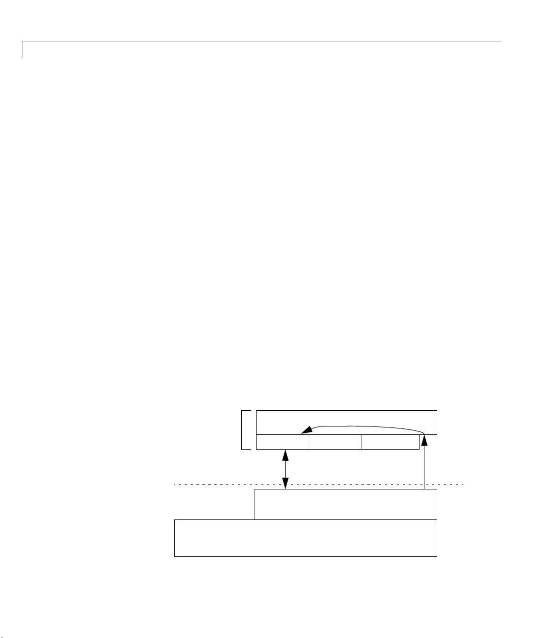
A Basic View of Toolbox-Engine-Adaptor Relationships
As discussed in “Toolbox Architecture” in Chapter 1, the Data Acquisition
Toolbox consists of M-files, the data acquisition engine, and adaptors. Each of
these components is used in a typical data acquisition session; although the
user only interfaces to the hardware through MATLAB code, the MATLAB
code uses the engine to create and manage the required data acquisition object,
and the engine uses the adaptor to control hardware and those properties’
changes that are deemed to be important to the adaptor. These relationships
are shown graphically below.
2-2
MATLAB
Adaptor Object
AI Object
Adaptor
Modify/Control
DAQ Engine
AO Object DIO Object
Create
COM
Page 27

Example: an Analog Input Session
A typical toolbox session using an analog input object is shown.
ai = analoginput('winsound');
set(ai,'SampleRate',11025)
set(ai,'Tag','WinsoundObject')
addchannel(ai,1);
set(ai.Channel,'InputRange',[-.5 .5])
start(ai)
wait(ai, 5);
data = getdata(ai);
delete(ai.Channel(1))
delete(ai)
Each command is described below.
Creating an Analog Input Object
The following command creates an analog input object associated with a sound
card.
Example: an Analog Input Session
ai = analoginput('winsound');
The analoginput M-file calls the data acquisition engine to construct the
analoginput object. When the constructor is first called, the engine must
determine what COM object to create. It does this by enumerating all class IDs
of objects that implement CATID {6FE55F7B-AF1A-11D3-A53600902757EA8D} (MATLAB Data Acquisition Adaptor), and then asks for the
short name of that GUID. In this case, the engine matches the short name to
winsound adaptor. The engine then constructs an mwAdaptor object and
the
calls the object’s
The adaptor’s
OpenDevice method for creating the analog input object.
OpenDevice method is responsible for creating a new device and
initializing it. Typically, this is done by creating a new COM object that
implements the appropriate interfaces. After creating the new object, the
engine interface can then be used to identify the characteristics of the current
driver or device to the MATLAB user. You can also create device-specific
properties at this time. The adaptor can also register an interest in some
properties by setting the User value of the property. This value serves two
purposes: Any value other than 0 causes the engine to call the
SetProperty
2-3
Page 28

2 Tutorial
method when the property is changed, and the value can be used in the
SetProperty method to identify the property being modified.
The
Open method creates any device-specific properties and defines any
device-specific values for existing properties. For example, the
adaptor has two device-specific properties:
StandardSampleRates. Both these properties are created with the
CreateProperty method of the IPropContainer interface. When the property
is created, a pointer to the
returned that allows you to call
IProp interface for the property just created is
IProp methods. The IProp methods allow you
to configure your property. For example, the
BitsPerSample and
IProp interface contains methods
winsound
that allow you to display the possible settings of the property, the default value
of the property, and the current value of the property.
Configuring the Sampling Rate
The following command configures the sound card to a sampling rate of 11.025
kHz.
set(ai,'SampleRate',11025)
The set M-file calls the data acquisition engine. In the Open method the
adaptor requested a notify on change for the
engine notifies the adaptor when you set the property to a new value. The data
acquisition engine calls the adaptor’s
SetProperty method with two input
arguments. The first input argument is a pointer to the
property being set. The second input argument is the value that the property
is being set to. Therefore, in this example, the first input argument is a pointer
SampleRate IProp interface, and the second input argument contains a
to the
pointer to
11025.
SampleRate property, and so the
IProp interface for the
2-4
From within the adaptor’s
SetProperty method, you can determine which
property is being set by examining the user value passed into the function. This
value can be compared to the values for each property that you have registered
with the engine.
Configuring the Object Tag
The following command configures the analog input object’s Tag property to the
string
WinsoundObject.
set(ai,'Tag','WinsoundObject');
Page 29

Example: an Analog Input Session
The set M-file calls the data acquisition engine. The Tag property was not
registered by the adaptor. Therefore, when you configure the property, the
engine modifies the value and does not notify the adaptor of the change.
Adding Channels to the Analog Input Object
The following command adds one channel to the analog input object ai.
addchannel(ai,1);
The addchannel M-file calls the data acquisition engine. The engine then calls
the adaptor’s
ChildChange method. This gives the adaptor the opportunity to
initialize the hardware and do any error checking for the channel that is added.
Configuring the Channel’s Input Range
The following command configures the channel’s InputRange property to
accept voltages between -5 and 5 volts.
set(ai.Channel,'InputRange',[-.5 .5]);
The set M-file calls the data acquisition engine. The engine then calls the
adaptor, because the
(within the adaptor's
adaptor's
SetChannelProperty method. SetChannelProperty takes four input
arguments. The first input argument is a pointer to the
channel property being modified. The second input argument is a pointer to the
IPropContainer interface for the channel being modified. The third input
argument contains a pointer to the
in Appendix C, “Engine Structures.” The last input argument contains the new
property value.
InputRange property was registered with the engine
Open method). The data acquisition engine calls the
IProp interface for the
NESTABLEPROP structure, which is described
Note The InputRange property is typically a combination of the hardware
device’s input range and the gain for a channel. For example, a hardware
input range of +/- 5 V with four gain settings of 1, 2, 5, and 10 results in
possible InputRange values of [-5 5], [-2.5 2.5], [-1 1], and [-0.5 0.5].
Starting the Analog Input Object
The following command starts the analog input object.
2-5
Page 30

2 Tutorial
start(ai);
wait(ai, 5);
The start M-file calls the data acquisition engine. The engine then calls the
adaptor’s
The
Start method.
Start method is responsible for initializing any routines necessary for
acquiring data from the hardware. Because triggering is by default immediate,
the engine then calls the adaptor’s
Trigger method, which starts the
acquisition. The adaptor must then run in the background using callbacks or a
separate thread. The buffers of data are transferred between the adaptor and
the data acquisition engine with the
IDaqEngine interface. The adaptor uses the GetBuffer method to obtain an
GetBuffer and PutBuffer methods of the
empty buffer from the data acquisition engine. When the buffer is filled with
data acquired from the hardware, the adaptor returns the buffer to the data
acquisition engine with the
PutBuffer method.
When the number of samples requested has been returned from the adaptor to
the data acquisition engine, the engine calls the adaptor's
The
wait M-file waits until the specified object has stopped, or a
Stop method.
particular time has passed (in this case, 5 seconds). The engine knows that the
adaptor has stopped when it receives a Stop Event notification from the
adaptor.
2-6
Extracting Data from the Engine
The following command extracts all the data from the engine and stores it in
the MATLAB variable
data = getdata(ai);
data.
The getdata M-file calls the data acquisition engine, which returns the data
buffered in the engine to the specified MATLAB variable. If the number of
samples requested by
getdata is not available, the engine blocks until the
adaptor returns the number of samples requested, or errors if the time
specified by
TimeOut elapses.
Deleting a Channel
The following command deletes the channel from the analog input object.
delete(ai.Channel(1))
Page 31

Example: an Analog Input Session
The delete M-file calls the data acquisition engine, which in turn calls the
adaptor’s
ChildChange method.
Deleting an Analog Input Object
The following command deletes the channel from the analog input object.
delete(ai)
The delete M-file calls the data acquisition engine, which calls the adaptor’s
destructor method. This should stop the device (call the
device was running, and close the hardware.
Stop method), if the
2-7
Page 32

2 Tutorial
Example: an Analog Output Session
A typical toolbox session using an analog output object is shown.
ao = analogoutput('winsound');
set(ao,'SampleRate',11025)
set(ao,'Tag','WinsoundObject')
addchannel(ao,1);
set(ao.Channel,'OutputRange',[-.5 .5])
data = sin(linspace(0,2*pi,8000));
putdata(ao,data')
start(ao)
wait(ao, 2);
delete(ao.Channel(1))
delete(ao)
The analgoutput, set, and addchannel commands are not described here
because they are functionally identical to the analog input commands
described in “Example: an Analog Input Session” on page 2-3. The
sin(linspace()) command is not described because it is handled entirely
within MATLAB. All other commands are described below.
2-8
Queuing Data in the Engine
The following command queues data in the engine.
putdata(ao,data')
The putdata M-file calls the data acquisition engine, and the data is converted
to the native data type and stored within the engine for output to the hardware.
Starting the Analog Output Object
The following command starts the analog output object.
start(ao)
The start M-file calls the data acquisition engine, which in turn calls the
adaptor's
The
outputting data that has been queued in the data acquisition. It often primes
the output with data before the trigger function is called. The engine then calls
the
Start method.
Start method is responsible for initializing any routines necessary for
Trigger function, at which point the hardware should be started. The
Page 33

Example: an Analog Output Session
buffers of data are transferred between the adaptor and the data acquisition
engine with the
GetBuffer and PutBuffer methods of the IDaqEngine
interface. The adaptor requests a buffer of data to be output from the data
acquisition engine with the
GetBuffer method. When the data buffer has been
output to the hardware, the adaptor returns the empty buffer to the data
acquisition engine with the
PutBuffer method.
For analog output objects, the adaptor must determine when the last buffer of
data is available for being output, call its own
event to the object’s
Flags field of the BUFFER_ST structure. The last buffer can also be detected if
the buffer obtained by the
null. An event can be posted with the
EventLog property. The last buffer can be detected with the
GetBuffer method of the IDaqEngine interface is
IDaqEngine's DaqEvent method.
Stop method, and post a Stop
Deleting a Channel
The following command deletes the channel from the analog output object.
delete(ao.Channel(1))
The delete M-file function calls the data acquisition engine. The engine then
calls the adaptor’s
and performs any necessary error checking for the channel that is being
deleted.
ChildChange method. The adaptor configures the hardware
Deleting an Analog Output Object
The following command deletes the analog output object.
delete(ao)
The delete M-file calls the data acquisition engine. The engine then calls the
adaptor’s destructor method. This should stop the device (call the
and close the hardware.
Stop method)
2-9
Page 34

2 Tutorial
Example: a Digital I/O Session
A typical toolbox session using a digital I/O object is shown.
dio = digitalio('nidaq',1);
lin = addline(dio,0:3,'in');
lout = addline(dio,4:7,'out');
p = addline(dio,0:7,1,'in');
data = getvalue(lin);
putvalue(lout,5)
data2 = getvalue(dio);
delete(dio)
Each command is described below.
Creating a Digital I/O Object
The following command creates the DIO object dio associated with a National
Instruments board.
dio = digitalio('nidaq',1);
2-10
A digital I/O (DIO) device need not implement all the interfaces that are
required for an analog input or analog output device. When the device is
opened, it must fill in the
portlinemask properties with the correct values. Given these values, the
portdirections, portids, portlineconfig, and
engine maintains the line information and generates the correct calls to
SetPortDirection, ReadValues, and WriteValues. The standard property and
child (line) property methods are supported. However, the adaptors
implemented so far have not needed to use them.
The object should initialize its properties to the correct values before returning.
For a DIO object, the
portdirections, portids, portlineconfig, and portlinemasks.
daqhwinfo property structure must initialize values for
Adding Lines to the Digital I/O Object
The following command adds four input lines from the default port (port 0) to
the DIO object
lin = addline(dio,0:3,'in');
The addline command works the same as the addchannel command for AI and
AO objects in that the adaptor’s
dio.
ChildChange method is called. However, most
Page 35

Example: a Digital I/O Session
adaptors need not implement ChildChange, because typically no adaptor
actions are necessary when adding or removing lines.
The following command adds four output lines to the DIO object
lout = addline(dio,4:7,'out');
dio.
After the lines are added, a call to SetPortDirection(0,0xf0) is made to set
the port direction to output.
The following command demonstrates that you can also add lines in reverse
order.
p = addline(dio,7:-1:0,1,'in');
Reading Line Values
The following command reads the values from lines 0 to 3 of port 0 and stores
the values in the MATLAB variable
data = getvalue(lin);
data.
The engine issues the command ReadValues(1,PortList,Data) to the device,
which must then return the values from the specified ports. The adaptor does
not keep track of exactly what lines have been added, and returns all line
values in
Data.
Writing Line Values
The following command writes the value 5 to lines 4 through 7 (the four most
significant bits) of port 0.
putvalue(lout,5);
The write is performed by calling WriteValues(1,PortList,Data,Mask)
Portlist, Data, and Mask are pointers to an array. Portlist points to 0,
where
Data points to 0x50, and Mask points to 0xf0.
The following three commands illustrate alternative ways to write the value 5
to port 0:
putvalue(lout,[1,0,1,0])
putvalue(dio.lines(8:-1:5),10);
putvalue(lout(4:-1:1),[0,1,0,1])
2-11
Page 36

2 Tutorial
Reading Line Values
The following command reads the values from all currently configured lines:
data2 = getvalue(dio);
The read is performed by calling ReadValues(2,PortList,Data).
Deleting a Digital I/O Object
The following command deletes the channel from the digital I/O object:
delete(dio);
It is up to the implementation to decide what state any output lines are left in.
The engine releases its reference to the
reference to the
Note The engine implements a pseudo line system and caches the values
written to output lines. It also takes care of reordering the lines (and data) for
the user.
mwAdaptor object.
mwDevice object and then releases its
2-12
Page 37

Step-by-Step Instructions for Adaptor Creation
Overview: Building the Adaptor . . . . . . . . . . . 3-2
Toolbox Adaptors . . . . . . . . . . . . . . . . . 3-3
About the Demo Adaptor Software . . . . . . . . . . 3-7
Stage 1 Select Supported Features . . . . . . . . . . . . . . . . . . . 3-9
Stage 2 Create the Adaptor Project and Adaptor Class 3-12
Stage 3 Implement the Analog Input Subsystem . . . . . . 3-18
Stage 4 Implement the Analog Output Subsystem . . . . 3-46
3
Stage 5 Implement the Digital I/O Subsystem . . . . . . . . 3-54
Page 38

3 Step-by-Step Instructions for Adaptor Creation
Overview: Building the Adaptor
This chapter provides step-by-step instructions for building an adaptor for your
hardware. Starting with the demo adaptor provided with the Data Acquisition
Toolbox, you can develop a complete adaptor, implementing all the
functionality available in the Data Acquisition Toolbox for your hardware,
using these instructions.
In this chapter, you learn how to build the adaptor by following these stages:
1 Choose the features of the Data Acquisition Toolbox the adaptor will
implement.
2 Create the Adaptor project and Adaptor class, based on the demo adaptor
supplied by The MathWorks.
3 Implement the Analog Input object code (if required).
4 Implement the Analog Output object code (if required).
5 Implement the Digital I/O object code (if required).
3-2
For each of the stages, the specific actions required to complete that stage are
discussed in this chapter. The stages have been designed so that testing can
take place often, and changes are typically restricted to a few files and methods
within one class.
Note Although this chapter discusses the steps required to implement each
stage, details of how to interact with properties, deal with buffers, and handle
event messaging are documented in later chapters. Refer to those chapters as
necessary.
The stages of development rely heavily on the demo adaptor source code
provided with the Adaptor Kit. In many instances, this document also refers to
existing adaptors supplied with the Data Acquisition Toolbox. Refer to the code
for these adaptors where necessary.
Page 39

Toolbox Adaptors
The technologies used in the adaptors shipped with the Data Acquisition
Toolbox have been presented in this document as approaches for implementing
your own adaptor. Each adaptor provides a unique combination of the
implementation approaches presented in this manual. The following sections
explain how each adaptor has been implemented. The code for each adaptor is
in a subdirectory of the Data Acquisition Toolbox. You can find the source code
$MATLABROOT\toolbox\daq\daq\src directory.
in the
The winsound Adaptor
The winsound adaptor is used to communicate with Windows-compatible sound
cards. The adaptor uses the Windows multimedia drivers and buffers acquired
data using multibuffering with direct callback threads.
This adaptor is the most basic of all the adaptors. However, because of the
power of the Windows multimedia device interface, it uses an efficient
acquisition method: This adaptor uses a linked list of buffers to acquire or
output data. The multimedia device is capable of filling (or emptying) these
buffers in the order that they are passed to the device. A thread is created to
feed buffers to the device from the engine, and to take the filled buffers from
the device and return them to the engine. The thread is paced with an event
generated by the device driver each time a buffer is filled. This driver also
supports variable data types.
Toolbox Adaptors
Note This adaptor was written prior to complete implementation of the
current Adaptor Kit. Although the concepts used in the adaptor are similar to
those presented here, you will find that some of the actual implementation of
code is more low-level than the ideas presented in this document.
The mcc Adaptor
The mcc adaptor is used to communicate with Measurement Computing devices.
The adaptor uses the Universal Library drivers, and buffers acquired data
using circular buffers with timer callbacks. It also implements software clocking.
3-3
Page 40

3 Step-by-Step Instructions for Adaptor Creation
The Measurement Computing adaptor has two unique features: First, because the
Universal Library does not support callbacks, this adaptor uses a timer to poll
the current acquisition. It does this by using the Windows multimedia timer
callback. The current transfer location is obtained from the Universal Library,
and the appropriate amount of data is then copied into or out of the circular
buffer. One disadvantage of this method is that there is no hardware guarantee
or protection for an overrun or an underrun condition. The adaptor tries to pick
a buffer size and a timer callback rate such that an overrun is unlikely, but
there is still the possibility that data can be lost.
The second unique feature of this adaptor is the support for software clocking.
Because some Measurement Computing devices do
adaptor implements a s
Note The Measurement Computing adaptor makes extensive use of many of the
Adaptor Kit macros used in this document. However, the Measurement Computing
adaptor does not implement the adaptor object separately from the analog
input class, so you should not use the entire adaptor as a template for creating
your own.
not have an onboard clock, this
oftware clock based on the Windows multimedia timer.
3-4
The nidaq Adaptor
The nidaq adaptor is used to communicate with National Instruments devices.
The adaptor uses the NI-DAQ driver, and buffers acquired data using circular
buffers with direct callbacks.
The NI-DAQ adaptor is one of the more extensive adaptors because of its
implementation of advanced triggering modes and the number of hardware
devices supported. It works by acquiring data to or from a circular buffer using
NI-DAQ’s callback and copy functions. A circular buffer is used because it is the
buffering mode supported by the NI-DAQ software. Many advanced triggering
modes are also supported by this adaptor. When the number of samples is
known and is sufficiently small, a burst acquisition is performed instead of
using continuous acquisition.
Page 41

Toolbox Adaptors
Note This adaptor was written prior to complete implementation of the
current Adaptor Kit. Although the concepts used in the adaptor are similar to
those presented here, you will find that some of the actual implementation of
code is more low-level than the ideas presented in this document.
The hpe1432 Adaptor
You use the hpe1432 adaptor to communicate with Agilent Technologies
E1432/33/34 devices. The adaptor uses the VXIplug&play driver, and buffers
acquired data using ping-pong buffers with callbacks.
For input data, the adaptor uses an unknown buffering method that is internal
to the VXIplug&play driver, and a callback to notify the adaptor when data is
available. In the callback function, a buffer of data is retrieved from the driver
and returned to the engine. For output data, the adaptor uses two buffers and
a vendor-supplied callback to send the data. The buffer size is defined by the
driver to have a maximum of 4096 values. Therefore, to simplify the copy
process, the adaptor limits the engine to this maximum buffer size. It also
supports more than 16 bit data output.
Note This adaptor was written prior to complete implementation of the
current Adaptor Kit. Although the concepts used in the adaptor are similar to
those presented here, you will find that some of the actual implementation of
code is more low-level than the ideas presented in this document.
The keithley Adaptor
You use the keithley adaptor to communicate with Keithley Instruments
devices. The adaptor uses the DriverLINX set of drivers, and implements direct
engine-driver buffer transfers using window messaging.
The Keithley adaptor supports a wide range of Keithley Instruments boards.
Because each board series uses a different device driver, the adaptor opens all
available DriverLINX drivers at initialization, and closes them when the
adaptor is destroyed. The adaptor can switch between software-clocked and
hardware-clocked acquisition as required.
3-5
Page 42

3 Step-by-Step Instructions for Adaptor Creation
A unique feature of the Keithley adaptor is the implementation of Window
message handling to monitor task progress. The adaptor uses a single message
window for all DriverLINX messaging, passing the message to the appropriate
subsystem as required. However, due to the implementation of the DriverLINX
drivers, the message window thread has to open all DriverLINX drivers in
order to receive any messages from those DLLs. Hence, two instances of
DriverLINX are open at any one time per driver installed on the machine.
The direct engine-adaptor buffering places some limitations on the minimum
size of the engine buffers. This is not enforced, but is rather communicated to
the user through warning messages when appropriate.
Note The Keithley adaptor has been implemented based solely on the
current Adaptor Kit ideas. You should refer to the Keithley adaptor for code
examples where possible.
3-6
Page 43

About the Demo Adaptor Software
The demo adaptor does not communicate with any actual hardware. Instead it
simulates data acquisition in order to demonstrate the basic functionality
common to most adaptors.
Features
The demo adaptor supports these features:
• Buffered acquisition
• Manual, software, and auto triggering
• Single-sample acquisition
• Saving (retrieving) collected data to (from) a MATLAB internal array
Limitations
The demo adaptor has these limitations:
• It works only with simulated data. The data is stored in the buffer
immediately after you open the device. This same buffer is reused whenever
data is required.
• It only supports software clocking. Note that the maximum software-clocked
sampling rate is 500 samples per second. Therefore, any adaptor you build
that uses software clocking includes this limitation. To achieve higher
sampling rates, you must use your hardware’s onboard timer. However,
supporting an onboard timer requires an entirely different software design,
which is described later in this guide.
About the Demo Adaptor Software
Modifying the Demo Adaptor
Modification of the demo adaptor takes place in each of the stages defined in
this chapter. Although you could simply modify the code from the demo adaptor
and create an adaptor named “demo” by building that modified adaptor code,
this chapter leads you through the process of creating your own project and
importing components of the demo adaptor into that project one at a time. In
this way, you can test modifications and restrict problems to a single file in the
project, which makes implementation quicker and easier to deal with.
The demo adaptor code contains many
3-7
Page 44

3 Step-by-Step Instructions for Adaptor Creation
// TODO
...
// END TODO
comment segments. These segments of comment code should be used in
conjunction with the steps outlined in this chapter, in order to produce a
successful adaptor with minimal trouble.
3-8
Page 45

Stage 1 Select Supported Features
The first stage of writing your adaptor is deciding which features of the Data
Acquisition Toolbox to support. Your decisions should be based on
• Hardware capabilities: Can the hardware provide the specified feature?
• Driver knowledge: Does the software driver support the required
programming requirements?
• Available time: Some aspects of implementation can be completed relatively
quickly, while others require more programming and testing time.
In general, these decisions are driven by the first two points, and only rarely
by the last.
The following questions provide an implementation roadmap for you to follow.
The questions provide a hierarchy of implementation possibilities based on
implementation complexity; as the list continues (for each subsystem) the
implementation becomes more complex. Each successive point is also inclusive:
to implement that point requires implementation of each previous point.
About the Demo Adaptor Software
1 Will the adaptor support analog input?
a Single-value transfers only?
b Buffered transfers (logging to memory and/or disk) using software
clocking?
c Hardware-clocked buffered transfers?
d Hardware triggering and/or gated acquisition?
2 Will the adaptor support analog output?
a Single-value transfers only?
b Buffered transfers (logging to memory and/or disk) using software
clocking?
c Hardware-clocked buffered transfers?
d Hardware triggering and/or gated acquisition?
3 Will the adaptor support digital I/O?
a Will any digital ports be configurable for write/read?
3-9
Page 46

3 Step-by-Step Instructions for Adaptor Creation
b Will any digital lines be configurable for write/read?
Based on the questions posed above, a roadmap to implementation can be
identified. This roadmap is presented in the following table as methods that
must be implemented for each of the steps defined above.
Table 3-1: Classes and Methods to Be Implemented in the Adaptor
Question Class/Methods to Implement
1) Analog Input AnalogInput class (derived from ImwDevice and ImwInput)
Open, SetDaqHwInfo methods.
1a) Single-value A/D
1b) Software-clocked
acquisition
1c) Hardware-clocked
acquisition
1d) Hardware
triggering or gated
acquisition
2) Analog Output
2a) Single-value D/A
2b) Software-clocked
transfer
2c) Hardware-clocked
transfer
2d) Hardware
triggering or gated
transfers
GetSingleValue and/or GetSingleValues methods.
No additional methods are required, but the adaptor must call
EnableSwClocking to set up correct sample rates.
Start, Trigger, Stop methods, and probably SetProperty,
ChildChange, and SetChannelProperty methods, as well as a message
handler.
Modify
Start, Trigger, and Stop methods, as well as property change
methods.
AnalogOutput class (derived from ImwDevice and ImwOutput)
Open, SetDaqHwInfo methods.
PutSingleValue and/or PutSingleValues methods.
No additional methods are required, but the adaptor must call
EnableSwClocking to set up correct sample rates.
Start, Trigger, Stop methods, and probably SetProperty,
ChildChange, and SetChannelProperty methods; message handler.
Modify
Start, Trigger, and Stop methods, as well as property change
methods.
3-10
Page 47

About the Demo Adaptor Software
Table 3-1: Classes and Methods to Be Implemented in the Adaptor (Continued)
Question Class/Methods to Implement
3) Digital I/O
3a) Port-configurable
I/O
3b) Line-configurable
I/O
Stages 2 through 4 discuss how to implement each of these methods.
By the end of Stage 1, you will have a roadmap defining how you will
implement your adaptor. Refer also to Appendix A, “Adaptor Kit Interface
Reference,” and Appendix B, “Engine Interface Reference,” for information on
the methods that all adaptors should implement (and which methods are
implemented in the Adaptor Kit).
Limitations of Software-Clocked Adaptors
One of the most important implementation issues is whether to support
hardware clocking in your adaptor. As long as you use the Adaptor Kit code,
software clocking is already implemented for your adaptor, and requires
minimal effort, as outlined in the section above. However, software clocking
has some limitations which might be too severe for your application:
• The maximum sample rate for any acquisition task is 500 Hz, regardless of
• You cannot use any hardware triggering without rewriting substantial
DigitalIO class (derived from ImwDevice and ImwDIO)
Open, SetDaqHwInfo, WriteValues, ReadValues methods.
SetPortDirection method, trapping DirectionValue of 0 (Input) or
0xff (Output).
SetPortDirection method, with variable DirectionValue settings.
the board’s published sampling rate and your computer’s processor speed.
portions of the adaptor code.
If you are able to achieve your desired objective within these limitations, then
you should not use anything other than software clocking. A complete adaptor,
however, should use the full features of the hardware for which the adaptor has
been written, and should implement hardware clocking.
3-11
Page 48

3 Step-by-Step Instructions for Adaptor Creation
Stage 2 Create the Adaptor Project and Adaptor Class
Once you have selected the required implementation details, you can create the
adaptor project. Use of a suitable compiler and IDE is required for this task.
This chapter assumes the use of Microsoft Visual Studio 2005 or 2008.
Although you are starting a new Microsoft Visual Studio project, you will make
extensive use of the demo adaptor code shipped with the Adaptor Kit by
importing that code into your project and modifying it. The benefit of starting
a new project is that modifications to the existing demo adaptor code are more
manageable. Adding the demo adaptor code initializes all Data Acquisition
Toolbox Engine interfaces, and creates shell classes and methods for
implementation of the custom-written adaptor.
The following sections describe how to implement this stage by completing the
following steps:
1 Choose a suitable name for your adaptor.
2 Create the Microsoft Visual Studio project.
3-12
3 Add the demo adaptor code to that project (including renaming the demo
files).
4 Test the adaptor with MATLAB.
In Stages 3 to 5, you will implement each of the subsystems of the adaptor.
Step 2.1 Adaptor and Project Naming
Before creating the adaptor, you should select a suitable name. In many cases,
the name would be the name of the data acquisition board manufacturer or
model. For example, if you are creating a board manufactured by “XYZ
Instruments” a suitable name is “xyz”. The name should not begin with
numbers, and should be sufficiently unique and representative of the
capabilities of the adaptor (if you are writing for a particular board, say the
“ad123”, you should name your adaptor after that board, i.e., “xyzad123”).
You must use all lowercase for the adaptor name, to conform to conventions
used on existing adaptors.
This adaptor kit provides examples based on a chosen adaptor name of “xyz”.
Page 49

About the Demo Adaptor Software
Note Do not use the word “adaptor” in your project name, as the project
name is used extensively in the COM object naming! Otherwise a user would
have to create an adaptor by referring to it as the “xyzadaptor” instead of just
by the board name, “xyz”.
Once you have named the adaptor, you can create the adaptor project by
starting a new project using the “ATL Com AppWizard”. You should not need
to use MFC, as all interaction with the adaptor takes place through MATLAB
and not other windows (the only exception is when you are creating adaptors
that use MFC, for example, the winsound adaptor).
All adaptors created to date are in-process servers. For the AppWizard, this
means selecting “Dynamic Link Library” as the server type. Use of out of
process servers has not been tested, and is likely to be more difficult, although
not impossible.
The created project forms the shell of the adaptor.
Step 2.2 Add Include, Link, and MIDL Directories to
Your Pro j e c t
To successfully compile the adaptor code, you must add the
$MATLAB\Toolbox\daq\daqadaptor\AdaptorKit directory to the following
include paths (
• To the “Additional include directories” option of the C/C++ Preprocessor
definitions panel.
• To the “Additional resource include directories” option of the Resources
panel.
• To the “Additional include directories” option of the MIDL panel.
Next you must add the
the $MATLAB\Toolbox\daq\daqadaptor\AdaptorKit directory.
You need to enable exception handling in your project. Select Project Settings
and select “All Configurations”. In the C/C++ tab, select “C/C++ Language” and
select the
$MATLAB refers to the directory in which MATLAB is installed):
Adaptorkit.cpp file to your project as source file from
Enable exception handling box.
3-13
Page 50

3 Step-by-Step Instructions for Adaptor Creation
Step 2.3 Define Adaptor Classes in the IDL File
The IDL file contains a definition of all COM interfaces defined in the project.
In this stage, you add the adaptor interfaces to the project, and the IDL file.
You should complete the following tasks in this stage (consult the demo
adaptor IDL file
demo.idl for more information):
• Add a line to import the
• Copy the implementation of the
daqmex.idl file.
demoadapt class into your IDL file. The
specific lines to copy are given below:
[
uuid(CE932327-3BD9-11D4-A584-00902757EA8D),
helpstring("demoadapt Class")
]
coclass demoadapt
{
[default] interface ImwAdaptor;
};
Note You must change the UUID by running GUIDgen to create a new
UUID, and you must change the references to “
demo” to the name of your
adaptor.
Note that this definition must appear within the definition of the type library.
Step 2.4 Add the Demo Adaptor Class Code
Copy the files demoadapt.h and demoadapt.cpp into your project directory, and
rename them by replacing “
this is to perform a global search and replace on both files, replacing “
with the name of your adaptor.
demo” with your adaptor name. The best way to do
demo”
3-14
You must remove or comment out some portions of the adaptor code in order to
test the adaptor in the next step.
• Remove the
#include lines that import the Analog Input and Analog Output
header files into your adaptor code. You will add those in later stages.
• Comment out the blocks of text surrounded by
Page 51

About the Demo Adaptor Software
//TO_DO
...
//END TO_DO
code segments in the adaptor’s OpenDevice method. You will require that
code in later stages, and you do not actually create a device until that stage.
Make the following changes to the main project file (
• Add a
#include for the adaptor header in the main project.
xyz.cpp in this example):
• You also need to add the adaptor definition to the OBJECT MAP in the main
project file. As an example, the following entry would be made for the
adaptor named “
BEGIN_OBJECT_MAP(ObjectMap)
OBJECT_ENTRY(CLSID_xyzadapt, Cxyzadapt)
END_OBJECT_MAP()
xyz”:
The class ID of your adaptor is generated automatically by the MIDL
compiler.
Building and Testing the Demo Adaptor
You should now be able to build and test your demo adaptor, using the Debug
settings. Once the adaptor has successfully built, you should be able to launch
MATLAB and register and query the adaptor using the following MATLAB
code:
daqregister <PathToProject>\Debug\<adaptorname>.dll
daqhwinfo <adaptorname>
where <PathToProject> is the full path to your adaptor project and
<adaptorname> is the name of your adaptor. You should get back fictitious
results similar to the following:
» daqhwinfo xyz
ans =
AdaptorDllName: 'c:\xyzadaptor\xyz.dll'
AdaptorDllVersion: '1, 0, 0, 1'
AdaptorName: 'xyz'
BoardNames: {'xyz Board 0' 'xyz Board 1'}
InstalledBoardIds: {'0' '1'}
ObjectConstructorName: {2x3 cell}
3-15
Page 52

3 Step-by-Step Instructions for Adaptor Creation
If this is successful, you are ready to implement the next step of the adaptor. If
the results are not similar, or if you get an error message, you need to check
that all steps outlined previously have been carried out.
Step 2.5 Modify the Adaptor Class AdaptorInfo()
Method
In Step 2.3, the adaptor reported fictitious board information. The previous
step simply confirmed that the adaptor was compiling correctly, and
registering as a valid data acquisition adaptor object. In the final step of Stage
2 you should implement code that checks the installed hardware on the system
by modifying the
information about the installed hardware systems supported by the adaptor.
Typically, this would take the form of querying a device driver for any board
information that it can find, from the registry or other means.
AdaptorInfo method of the adaptor class to provide
For an example of how
Measurement Computing adaptors.
Note The AdaptorInfo method makes extensive use of SafeArrays to pass
information back to MATLAB. See “Passing Arrays to MATLAB Using Safe
Arrays” in Chapter 4 for some ideas on how to do this in your adaptor.
The objective of this step is to make the information reported by a call to
daqhwinfo <adaptorname>
return the correct information for installed boards. For example, a call to the
Keithley adaptor on a machine with four hardware devices produces the
following results:
>> d=daqhwinfo('keithley')
d =
AdaptorDllName: [1x58 char]
AdaptorDllVersion: 'Version 1.1 (R12.1+) 23-Aug-2001'
AdaptorName: 'keithley'
BoardNames: {'KPCI-1801HC' 'KPCI-3110' 'KPCI-3108'
'KPCI-PIO96'}
InstalledBoardIds: {'0' '5' '1' '2'}
ObjectConstructorName: {4x3 cell}
AdaptorInfo is implemented, consult the Keithley or
3-16
Page 53

About the Demo Adaptor Software
Typically device drivers provide some mechanism for differentiating between
multiple hardware devices. The Data Acquisition Toolbox assumes that boards
are referenced by a unique integer board identifier, listed as the
InstalledBoardIds field from the result of the daqhwinfo call. If the device
driver for your adaptor does not implement this system, you should enforce a
board identifier on each unique board found by the device drivers, using an
appropriate convention. In the example above, four Keithley Instruments
boards have been installed on the machine, and their board IDs are 0, 5, 1, and
2, respectively.
ObjectConstructorName field returned by the daqhwinfo call lists the
The
object constructor code that can be used to create each of the Analog Input,
Analog Output, and Digital I/O subsystems (the columns of the cell array) for
each board (the rows of the cell array). If your adaptor is not implementing any
of the subsystems, you should remove the constructor string for that particular
subsystem. Similarly, if some boards implement a system while others do not,
you should leave the unsupported subsystem columns empty for that row of the
cell array.
3-17
Page 54

3 Step-by-Step Instructions for Adaptor Creation
Stage 3 Implement the Analog Input Subsystem
Although all subsystems of an adaptor should be considered equally important,
the most commonly implemented subsystem is analog input (since most users
of the Data Acquisition Toolbox require measurement of real-world signals).
The Adaptor Kit therefore implements the analog input subsystem as the first
subsystem of the adaptor. This stage presents a significant discussion of the
techniques used in developing the adaptor’s subsystems; the steps required to
implement the Analog Output and Digital I/O subsystems are similar. Stages
4 and 5 therefore draw heavily on material discussed in this stage.
Implementation of the Analog Input subsystem takes place in the following
steps:
1 Select the default values, ranges, and other characteristics of the analog
input subsystem properties.
2 Create the Analog Input COM interface and class definitions in the IDL file,
and incorporate the demo adaptor analog input implementation in your
project.
3-18
3 Modify the OpenDevice method of the adaptor class to create the required
subsystem when requested.
4 Modify the Open and SetDaqHwInfo methods of the Analog Input class to
handle device initialization, create custom properties, and set defaults and
ranges for all properties.
5 Implement the SetProperty and SetChannelProperty methods of the
Analog Input class to handle property changes.
6 If necessary, overload the ChildChange method of the Analog Input class to
handle channel addition and removal.
7 Implement the GetSingleValue method if software clocking is to be used.
8 Implement the GetSingleValues method if the device driver supports easy
single acquisition from multiple channels.
Page 55

About the Demo Adaptor Software
9 Implement the Start, Trigger, and Stop methods for buffered acquisition.
Typically, this step involves writing buffering routines and message
handlers, and might require multithreading of the adaptor.
Each of these steps is discussed in detail in the following sections.
Note You should use the answers to the questions posed in Stage 1 to decide
which of the preceding steps you will implement in your adaptor.
Step 3.1 Select Property Values, Ranges, and
Defaults for Analog Input
In order to control the behavior of a task (such as duration and volume of
acquisition, type of triggering, clocking, and event callbacks) the MATLAB
user modifies the properties of the Data Acquisition Toolbox
object representing the data acquisition hardware he/she is using. The adaptor
must use the property values during acquisition tasks to control driver
settings, return messages, and start and stop acquisition. The adaptor must
also provide the data acquisition engine with appropriate properties, ranges,
and default values for the specific hardware referenced by the adaptor.
Successfully creating an adaptor therefore requires careful thought about the
existing common Analog Input subsystem properties, and the addition of
adaptor-specific properties where appropriate.
analoginput
For both common and adaptor-specific properties, the adaptor might need to
control default values of a property in response to user changes in any
associated properties (for example, when the user changes the
ChannelSkewMode property, the range for the ChannelSkew property needs to
change to reflect the new mode). The first step in building any subsystem is to
plan these default values and ranges and decide on any additional properties
that are required in order to describe the hardware completely. For example,
the Keithley adaptor implements stop triggers using various additional
properties such as
Typically, this step consists of compiling a propinfo table of all common
properties for the particular subsystem, and filling in the following
information:
• Type: The MATLAB data type (one of
StopTriggerType, StopTriggerChannel, etc.
double or string)
3-19
Page 56

3 Step-by-Step Instructions for Adaptor Creation
• Constraint: The constraint on the property. Typically, this is Bounded, if the
property lies within a defined range,
enumerated list of available values, or
value.
• Constraint Value: The limits for a bounded constraint, or the list of
possible values for an enumerated list.
• Default Value: The value of the property when the object is first created. If
this might change, indicate all possible values with a note.
• Read Only: A flag indicating whether the property can be changed by the
user.
• Read Only Running: A flag indicating that the property cannot change
while an acquisition task is running.
• Device Specific: If the property is specific to the particular adaptor or is
defined by the engine.
• Attach: Whether the property is to be attached to (for information on
attaching to properties, see “Attaching to a Property” in Chapter 4).
• Notes: Any particular note about the property, including the source of the
default values (for example, the driver, or an INI file), how the property
might change based on other properties, and any additional implementation
information.
Enum if the property is one of an
None if the property can take on any
3-20
The
propinfo table should reflect the state of the desired output from a call to
propinfo method of the analoginput object. Thus, when you run
the
propinfo(analoginput(<adaptor>))
the result should be the data presented in the propinfo table. The output of
the MATLAB code given above provides a test to confirm that these properties
have been created and initialized successfully.
The table should include only those properties that are directly related to the
device hardware, and should not include properties that are used for logging to
disk, function callbacks, event information, or internal housekeeping.
For a complete list of properties supported by the adaptor, consult the Data
Acquisition Toolbox User’s Guide
A direct consequence of producing this table is discovering which properties
your adaptor will have to monitor closely. Monitoring of a property involves
registering that property with the data acquisition engine, effectively notifying
Page 57

About the Demo Adaptor Software
the engine that the adaptor has a particular interest in being notified
whenever the user changes that property. This process, called attaching to the
property, allows methods within the adaptor to be called whenever that
property changes. Consequently, the adaptor would be able to change other
property enumerated lists, or perform additional checks on a selection of
properties to ensure that the subsystem does not perform illegal operations
when an acquisition is started. For more information on attaching to
properties, see “Attaching to a Property” in Chapter 4.
A sample
propinfo table is presented in Table 3-2, showing only two properties
from an adaptor.
Table 3-2: Sample of Propinfo Table for Analog Input Object
Property/Field Value
ChannelSkew
Type
Constraint
Constraint Value
Default
ReadOnly
ReadOnly Running
Device Specific
Attach
Note
Double
fixed
for Minimum
5e-6
1/SampleRate for Equisample
if Minimum supported, else 1/1000.
5e-6
1
1
0
0
Check driver for burst mode support.
ChannelSkewMode
Type
Constraint
String
Enum
3-21
Page 58

3 Step-by-Step Instructions for Adaptor Creation
Table 3-2: Sample of Propinfo Table for Analog Input Object (Continued)
Property/Field Value
Constraint Value Minimum
Default Minimum
Equisample
ReadOnly
ReadOnly Running
Device Specific
Attach
Note
0
1
0
1
Mimimum
sets
ChannelSkew.
only if ADBURST is supported. Change
The outcome of Step 3.1 is a document that forms the blueprint for the
implementation of properties in later steps of this stage.
Step 3.2 Add the Demo Analog Input Code to Your
Project
When the IDL file was created, only the adaptor component was included. The
IDL file must expose the Analog Input interface to the engine, so that the
engine can access the methods in the analog input implementation.
Both the interface and the class need to be defined in the IDL file. Specify the
interface prior to the specification of the Adaptor Type Library, so that the
library can use the new interface in the Analog Input class. The following tasks
should be completed in this stage:
• Add the interface definition prior to the type library definition. The Analog
Input interface should inherit from the
IDispatch interface is not currently implemented, the engine assumes that
the Analog Input interface inherits from
XYZ adaptor follows:
[
object,
uuid(E721C893-C230-4eae-9F78-B33E30F74B4E),
IDispatch interface (although the
IDispatch). Sample code for the
3-22
Page 59

About the Demo Adaptor Software
dual,
helpstring("IxyzAin Interface"),
pointer_default(unique)
]
interface IxyzAin : IDispatch
{};
• Be sure to change the UUID, using GUIDgen, so that your adaptor has a
unique ID.
• Add the Analog Input class to the type library (if using the following code, be
sure to change the UUID of your class using GUIDGen):
// Define the xyzAin class:
[
uuid(83D8B96C-FE9A-46c7-AAB9-6B3C67FDE863),
helpstring("xyzAin Class")
]
coclass xyzAin
{
[default] interface IxyzAin;
interface ImwDevice;
interface ImwInput;
};
The Analog Input class should inherit the ImwDevice and ImwInput
interfaces, and your Analog Input interface defined in the adaptor.
• Copy the Analog Input files from the demo adaptor, renaming the files
appropriately. In order to facilitate the search and replace operation
described below, you should simply replace the word “demo” in the filenames
with your adaptor name. For example, the file
xyzain.cpp.
demoain.cpp would become
• Search for all instances of the word “demo” and replace that with your
adaptor name.
Note Remember to do this with both the .cpp and the .h files. Unfortunately,
the current Microsoft Visual C IDE does not support search and replace across
multiple files.
3-23
Page 60

3 Step-by-Step Instructions for Adaptor Creation
In the next step, you test the changes made in this step by providing sufficient
code to enable the creation of the your analog input object as a duplicate of the
demo adaptor with a new name.
Step 3.3 Modify the OpenDevice Method of the
Adaptor Class
In this step of the implementation of the analog input object, you ensure that
the renamed demo adaptor still works in MATLAB.
• Uncomment the analog input construction statements in the
method of the Adaptor class. Be sure to include the Analog Input class
header file in the adaptor class implementation file.
• Compile the project, and you should be able to launch MATLAB and create
an analog input object for your adaptor:
ai = analoginput('xyz');
If the compilation fails, you should ensure that all header files have been
created, and that your analog input class name is consistent throughout the
project. Also ensure that all the steps from the previous stage have been
implemented as well.
Your adaptor should now contain a complete analog input object, which
implements software clocking on a fake acquisition channel (the acquisition
returns a sine wave from an internal function, and not from any hardware
device). In future stages of the analog input implementation, you will
progressively implement hardware acquisition tasks. The first of these stages
is t o ensure tha t th e a d a p t or’s properties are initialized correctly, possibly from
hardware device detection.
OpenDevice
Step 3.4 Modify the Analog Input Open and
SetDaqHwInfo Methods
The Open method is called by the Adaptor class OpenDevice method to create
an analog input subsystem for a particular device. The
responsible for checking that the required device has the requested subsystem,
initializing the subsystem hardware (if necessary), and configuring the
subsystem properties correctly.
Open method is
3-24
You create analog input subsystems by specifying two parameters: the adaptor
name and the device ID. Your adaptor code needs to use the device ID to
Page 61

About the Demo Adaptor Software
provide the device driver with a specific reference to the desired hardware
device. The device ID is passed as the second parameter of the
Open method.
The first parameter is a pointer to the Engine interface, and this should also be
stored by the adaptor to gain access to engine methods.
Open method typically also calls the SetDaqHwInfo method, to define
The
hardware and driver information for the subsystem.
The demo adaptor provides a sample
Open method that illustrates the basic
ideas of opening an analog input subsystem:
• The base engine’s
defines a variable
Open method is called. This creates a link to the engine and
_engine containing a pointer to the engine’s interface
methods.
• The
ClockSource and InputType properties are initialized as remote
properties (for a discussion of properties, see Chapter 4, “Working with
Properties”).
• The
ClockSource and InputType properties are modified to reflect the demo
adaptor state more closely.
• The
All adaptors need to follow the preceding pattern (the
be replaced by a call to
DaqHwInfo properties are set by the call to InitHwInfo.
InitHwInfo method can
SetDaqHwInfo), and include the following additional
code:
• Code to initialize the device driver and hardware, if necessary
• Code to check the device ID to confirm that the requested hardware exists
• Code to attach to the required properties listed in Step 3.1 (see “Attaching to
a Property” in Chapter 4)
• Code to create adaptor-specific properties
A full discussion of interaction with properties is given in Chapter 4, “Working
with Properties.”
Because all
implement
Open methods typically include a call to SetDaqHwInfo, you should
SetDaqHwInfo prior to testing the hardware-specific adaptor.
The Data Acquisition Toolbox allows the user to query a specific subsystem to
obtain hardware information for that specific subsystem. A MATLAB user
would type the following code to obtain information about the XYZ adaptor
analog input device 5:
3-25
Page 62

3 Step-by-Step Instructions for Adaptor Creation
>> daqhwinfo(analoginput('xyz', 5))
Note You could split this MATLAB statement into two by assigning the
analoginput object to a variable. Either way, the Data Acquisition Toolbox
first creates the subsystem and then provides hardware information about
that subsystem.
The information for a call to a subsystem’s
calling the
SetDaqHwInfo method should also be called by the Open method to initialize
SetDaqHwInfo method of the requested subsystem. The
daqhwinfo method is obtained by
these values on startup.
The
SetDaqHwInfo method should use the _daqhwinfo IPropContainer
member variable defined in the I
inherits from
ImwDevice, and so already defines the _daqhwinfo member
variable. You put information into the
IPropContainer put_memberValue method. Table 3-3 lists the values that
the
you should place in
_daqhwinfo, and describes the type of data that should be
used for each member value. For sample code, see the
mwDevice interface class. Every subsystem
_daqhwinfo IPropContainer by using
SetDaqHwInfo method of
any of the adaptors included with the Data Acquisition Toolbox.
Table 3-3: SetDaqHwInfo Member Variables and Descriptions
Member Value Description Data Type (C++)
adaptorname
bits
coupling
devicename
Name of the adaptor String
Resolution of analog input subsystem Double
Device coupling (can be set to “Unknown”)String
Name of device. Typically, the name is
given as “
<adaptorname>AI-<id>”.
String
differentialids
gains
3-26
Channel IDs for differential channels (or
SafeArray (1 x nD)
empty if differential mode is not supported)
Allowable gains for channels SafeArray (1 x nG)
Page 63

About the Demo Adaptor Software
Table 3-3: SetDaqHwInfo Member Variables and Descriptions (Continued)
Member Value Description Data Type (C++)
id
inputranges
maxsamplerate
minsamplerate
nativedatatype
polarity
sampletype
singleendedids
subsystemtype
totalchannels
vendordriverdescription
Device ID Double
Allowable input ranges SafeArray (n x 2)
Maximum permissible sample rate Double
Minimum permissible sample rate Double
The data type of raw data that MATLAB
Varian tTy pe
can send to the hardware device. The
engine uses this value to convert voltages to
units that the hardware understands.
Vector of allowable polarities SafeArray
Either Scanning or Simultaneous Sample
Enum
and Hold (SSH)
Channel IDs for single-ended channels (or
SafeArray (1 x nS)
empty if single-ended mode is not
supported)
Always set to "AnalogInput" String
Total number of available channels Double
Description of the vendor driver used by the
String
adaptor for this device
vendordriverversion
Compiling and Testing Analog Input Property Creation
After creating the DaqHwInfo method and implementing the Open method
correctly, you should be able to compile your project and test your adaptor’s
analog input subsystem. Tests should take place in MATLAB, by creating an
analog input object and calling the
example, to test the XYZ adaptor, the code is as follows:
Version information for the vendor driver
used by the adaptor for this device
ai = analoginput('xyz');
String
daqhwinfo and propinfo methods. For
3-27
Page 64

3 Step-by-Step Instructions for Adaptor Creation
props = propinfo(ai)
dhinfo = daqhwinfo(ai)
You can now check the structures returned in props and dhinfo to ensure that
the correct default values and ranges are returned from a newly created object.
If you find that some values in
modifying the
information, check the
The next step in implementing analog input is ensuring that your adaptor
responds appropriately to changes in properties.
About Native Data Types and Bits Properties
The NativeDataType property is important for the correct operation of the
adaptor. This property is defined by the adaptor in the
and refers to the native data type that the adaptor uses to return values to the
engine or receive data from the engine. Typically, the native data type is an
unsigned 16 bit integer (CComVariant type
The Winsound adaptor, for example, provides support for 8 bit, 16 bit, and 32
bit native data types.
Open method. Similarly, if the dhinfo structure returns incorrect
props are incorrect, you can correct them by
SetDaqHwInfo method.
SetDaqHwInfo method,
VT_I2), but can be other data types.
3-28
Closely linked with the
defines the resolution of the analog input subsystem. The
to indicate to the user the actual resolution of the device; the
NativeDataType property is the Bits property, which
Bits property is used
NativeDataType
property is used by the engine to convert engineering values to native data, and
the reverse. Typically,
Bits should be less than or equal to NativeDataType.
Note The Data Acquisition Toolbox does not currently support floating-point
native data types (floats or doubles). If your adaptor does not support reading
or writing of raw data values, you must use a “fake” native data type and
convert the data to floating point when you read data from a MATLAB buffer
or write data to a MATLAB buffer.
Page 65

About the Demo Adaptor Software
Step 3.5 Implement the SetProperty and
SetChannelProperty Methods
In Step 3.4 you created default values and valid ranges for the properties you
defined in Step 3.1. In this step you implement code that monitors changes to
properties and/or channels in the analog input subsystem.
All Data Acquisition Toolbox adaptor properties are managed by the engine.
This includes any properties that are specific to your adaptor (as defined in
Step 3.1). The engine understands the following types of properties:
• Arbitrary strings. For example, the
Name property can be set to any string
by the user. Arbitrary strings have no specific range.
• Enumerated string values. For example, the
the engine sets to one of
Manual, Immediate, or Software. Also known as
TriggerType property, which
enum values, these properties can take on only one of a specific number of
values. Although the user sets these values using a string (or a portion of a
string) the values are stored internally as an enumerated data type. An
example of an enum type is the
one of
Manual, Immediate, or Software.
• Scalars. For example, the
TriggerType property, which can be set to
SampleRate property is a scalar value. Although
scalar properties can be any valid numeric data type in C++, MATLAB
converts the value to a double when presenting the information to the user.
Scalars typically have a range of valid values. The engine does not allow a
user to set the property to values outside that range.
• Vectors. For example, the
BufferingConfig property, which is a
two-element vector. The engine provides these properties to the user, but
adaptors cannot create vector properties.
For most properties, your adaptor need only specify the default values, ranges,
additional (or reduced) enumerated values for enum property types, and
read-only status. However, some properties need to be closely monitored by the
adaptor, because they can change the behavior of other properties, or need to
be checked with the values of other properties. The adaptor therefore would in
these circumstances need to be notified each time a user makes changes that
affect such properties.
The Data Acquisition Toolbox provides this functionality by allowing an
adaptor to attach to a property. The process involves attaching a user value on
that property with the engine. The user value can be any nonzero integer. The
3-29
Page 66

3 Step-by-Step Instructions for Adaptor Creation
Adaptor Kit provides functionality that makes registering and checking a user
value intuitive. For more information on attaching to properties, see
“Attaching to a Property” in Chapter 4.
For all analog input properties that are attached to by an adaptor, the engine
calls the
value and the new value that the user has specified. For all analog input
channel properties that are registered by an adaptor, the engine calls the
SetChannelProperty method of the analog input interface, passing similar
information. For instance, modifying the
SetChannelProperty.
The
defined by the Adaptor Kit) to determine which property has been modified.
You should perform one of the following functions in the
SetChannelProperty methods:
• Error, if the new value is invalid. The following example, from the Keithley
adaptor, checks whether the hardware supports the requested
property, and errors out appropriately:
SetProperty method of the analog input interface, passing it the user
SetProperty method can check the user value (using the USER_VAL macro
if (User == USER_VAL(pTransferMode))
{
if((long)(*val) == TRANSFER_DMA)
{
SelectDriverLINX(m_driverHandle);
if(!(DoesDeviceSupportDMA(m_pSR)))
{
}
m_usingDMA = true;
}
else
{
m_usingDMA = false;
}
}
InputRange of a channel calls the
SetProperty or
TransferMode
return Error(_T("Keithley: This device does not
support DMA Transfers."));
3-30
• Change the new value if the property needs to be quantized or set to values
that the hardware can implement. The following example from the
Page 67

About the Demo Adaptor Software
Measurement Computing adaptor calls UpdateRateandSkew to quantize the sample
rate and change the channel skew when the user changes the sample rate:
else if (User==USER_VAL(pSampleRate))
{
RETURN_HRESULT(UpdateRateAndSkew(pChannelSkewMode,*val));
_RequestedRate=*val;
*val=pSampleRate;
}
• Change the values, defaults, and/or ranges of other properties based on the
new value. The following example from the Measurement Computing adaptor
modifies the
TriggerType property:
else if (User==USER_VAL(pTriggerType))
{
if (static_cast<long>(*val)==HW_DIGITAL_TRIG)
{
pTriggerCondition->AddMappedEnumValue(GATE_LOW,
pTriggerCondition->AddMappedEnumValue(TRIG_HIGH,
pTriggerCondition->AddMappedEnumValue(TRIG_LOW,
pTriggerCondition=TRIG_NEG_EDGE;
pTriggerCondition.SetDefaultValue(TRIG_NEG_EDGE);
}
else if (static_cast<long>(*val)==HW_ANALOG_TRIG)
{
pTriggerCondition->ClearEnumValues();
pTriggerCondition->AddMappedEnumValue(GATE_NEG_HYS,
pTriggerCondition->AddMappedEnumValue(GATE_POS_HYS,
pTriggerCondition->AddMappedEnumValue(GATE_ABOVE,
pTriggerCondition->AddMappedEnumValue(GATE_BELOW,
TriggerCondition property based on changes to the
pTriggerCondition->ClearEnumValues();
pTriggerCondition->AddMappedEnumValue(GATE_HIGH,
L"GateHigh");
L"GateLow");
L"TrigHigh");
L"TrigLow");
L"GateNegHys");
L"GatePosHys");
L"GateAbove");
3-31
Page 68

3 Step-by-Step Instructions for Adaptor Creation
pTriggerCondition->AddMappedEnumValue(TRIGABOVE,
pTriggerCondition->AddMappedEnumValue(TRIGBELOW,
pTriggerCondition=TRIGABOVE;
pTriggerCondition.SetDefaultValue(TRIGABOVE);
RANGE_INFO *rInfo=*_validRanges.begin();
pTriggerConditionValue.SetRange(rInfo->minVal,
}
}
Once you have completed the SetProperty and SetChannelProperty methods,
you can test the changes you make to your properties, by compiling your
adaptor and modifying properties of the adaptor in MATLAB. The easiest
technique for modifying properties is to use the
MATLAB, by calling
ai = analoginput('xyz');
daqpropedit(ai)
L"GateBelow");
L"TrigAbove");
L"TrigBelow");
rInfo->maxVal);
daqpropedit function in
3-32
Page 69

About the Demo Adaptor Software
A view of the Data Acquisition Toolbox Property Editor is shown below.
For more information on
User’s Guide.
daqpropedit, consult the Data Acquisition Toolbox
Step 3.6 Implement the ChildChange Method
Data acquisition cannot take place without a list of channels from which to
sample data. The Data Acquisition Toolbox stores channels as children of the
analog input and analog output objects. Typically, an adaptor should know
when the user creates, removes, or reorders the channel list. If the adaptor
needs to track these changes to children, you must overload the
method. Adaptors typically take one or more of the following actions in
response to a call to
ChildChange:
ChildChange
3-33
Page 70

3 Step-by-Step Instructions for Adaptor Creation
• Ensure that the hardware can handle the additional or removed channel.
• Check that the number of channels is within the limits of the hardware’s
channel list.
• Check whether the added channel is repeated elsewhere in the channel list;
some hardware does not allow repeated channels in a channel list.
• Some hardware can only support a channel range; the user would have to
add channels in strict order, and the adaptor would have to check this order.
• Update maximum sample rates based on added or removed channels.
Most adaptors should also keep track of each channel’s required input range,
either as a channel gain or a channel gain code. This list is updated whenever
a channel is added or removed through
is changed through
method is usually implemented to deal with the channel list. For an example
of such a private method, see the
Understanding the ChildChange Type of Change Parameter
The ChildChange method is called whenever the channel list changes,
regardless of the reason for that change. Often it is useful to know why the
change occurred. The
the parameter
determine the reason for the change as follows:
ChildChange, and when the input range
SetChannelProperty. For this reason, a separate private
UpdateChans method in the Keithley adaptor.
ChildChange method is passed as the first argument to
typeofchange as a DWORD. Using typeofchange, you can
3-34
• If
(typeofchange & START_CHANGE) is true, then the ChildChange method is
being called before the change has taken place. You should check to ensure
that the change is valid, by querying the reason for the change (see below).
• If
(typeofchange & END_CHANGE) is true, then the ChildChange method is
being called after the change has happened. You should requery channel
properties and modify any other properties based on the modified channel
list.
• If you mask
(typeofchange & CHILDCHANGE_REASON_MASK), you are left with
the reason for the change, which can be one of
-
ADD_CHILD: A channel has been added.
-
REINDEX_CHILD: The channel list has been reordered.
-
DELETE_CHILD: A channel has been removed.
For examples of the use of the
adaptor’s
ChildChange method.
typeofchange parameter, see the Keithley
Page 71

About the Demo Adaptor Software
Testing the ChildChange Method
Once you have implemented the ChildChange method, you can test the
addition, removal, and modification of channels in your adaptor. A typical test
might look like the following:
>> ai = analoginput(‘xyz’);
>> ch(1) = addchannel(ai, 0);
>> ch(2:3) = addchannel(ai, [1 2])
>> ch(4) = addchannel(ai,1)
>> set(ch(3), 'InputRange', [0 10])
>> delete(ch(2))
Your particular tests should include testing that the adaptor produces an error
when too many channels are added, and that channel deletion is handled well.
Step 3.7 Implement the GetSingleValue Method
Up to now, the adaptor you have written does not actually read data from the
hardware device. The code you have written so far provides good housekeeping,
and a consistent interface to the user to ensure flexibility and access to
complete hardware capabilities while preventing invalid states in the adaptor.
In this step you write the first (and sometimes only) code that actually reads
values from the data acquisition hardware.
GetSingleValue method is called when
The
• The user requests data using the MATLAB
GetSingleValues is not implemented (see Step 3.8).
getsample function and
• The user has selected software clocking and starts an acquisition task.
Note Even if you have implemented GetSingleValues, you must implement
GetSingleValue if you support software clocking for your device. The engine
does not use GetSingleValues for software-clocked acquisitions.
GetSingleValue method should sample a single value from a single
The
channel. The
HRESULT GetSingleValue(int chan, RawDataType* value)
GetSingleValue method is defined as follows:
3-35
Page 72

3 Step-by-Step Instructions for Adaptor Creation
The channel number is defined by the variable chan, and the sampled raw data
value must be returned in
this code is as follows (note how the adaptor returns the value directly from the
device driver to
HRESULT Ckeithleyain::GetSingleValue(int chan, RawDataType*
value)
{
WORD ResultCode;
if (!m_isInitialized)
{
RETURN_CODE(InitializeDriverLINXSubsystem(m_pSR,
if (ResultCode != 0)
{
}
}
SetupDriverLINXSingleValueIO(m_pSR, chan,
m_chanGain[chan], SYNC);
DriverLINX(m_pSR);
if (m_pSR->result != 0)
{
return CComCoClass<ImwDevice>::Error(
}
GetDriverLINXAIData(m_pSR, (unsigned short*)value ,0,1,1);
return S_OK;
}
value. For example, the Keithley implementation of
value):
&ResultCode));
char tempMsg[255];
ReturnMessageString(NULL, ResultCode,tempMsg, 255 );
return CComCoClass<ImwDevice>::Error(tempMsg);
TranslateResultCode(m_pSR->result));
3-36
Testing GetSingleValue
When you have implemented this method, you can test acquisition of data by
calling
getsample with your analog input object, as follows:
ai = analoginput(‘xyz’);
addchannel(ai, 0); % Set up channel 0
s = getsample(ai); % Return a single value from channel 0
addchannel(ai, 1); % Add another channel
Page 73

About the Demo Adaptor Software
s2 = getsample(ai); % Return data from channels 0 and 1
For adaptors that implement software clocking only, this is the last method you
need to implement. Software-clocked adaptors should not require any
additional methods to acquire data, as the software clocking methods are
created in the Adaptor Kit code. For limitations on software-clocked adaptors,
see “Limitations of Software-Clocked Adaptors” on page 3-11.
For adaptors that implement internal clocking, you need to follow the
remaining steps of Stage 3.
Step 3.8 Implement the GetSingleValues Method
The GetSingleValues method should only be implemented if the device driver
supports the acquisition of a single immediate sample from multiple channels
in one driver call. For drivers that only allow single immediate samples from
one channel, the
takes care of looping through all channels in the channel list.
The
GetSingleValues method should simply implement code that acquires a
single immediate sample from all the channels defined in the channel list. The
result should be returned in a SafeArray vector, and should contain raw data
in the data type defined by the adaptor for that hardware.
GetSingleValue method is appropriate, as the engine then
A typical example of a
HRESULT CAin::GetSingleValues(VARIANT * Values)
{
UpdateChans(true); // Update channel lists.
TSafeArrayVector <unsigned short > binarray;
binarray.Allocate(_nChannels);
// Code to call hardware here.
// Return result in binarray
return binarray.Detach(Values);
}
GetSingleValues implementation is as follows:
When you have written the GetSingleValues method, you should retest the
adaptor using the
getsamples func tion from MATLAB. S ee Step 3.7 for sam ple
MATLAB code.
3-37
Page 74

3 Step-by-Step Instructions for Adaptor Creation
Step 3.9 Implement the Start, Trigger, and Stop
Methods
The final step in implementing the analog input subsystem is to provide
functionality for hardware-clocked or hardware-triggered acquisition tasks.
This final step is by far the most complex step in the implementation of the
analog input subsystem, and should not be implemented unless software
clocking is insufficient for your required task. If you are intending to
implement this step, it is assumed that you can configure the device driver to
continuously acquire data from a list of channels, clocking the device using the
hardware’s onboard clock. If this is not possible, you will have to resort to
software clocking and live with the limitations of that implementation.
Hardware-clocked adaptors require a number of technologies to be
implemented correctly in order to handle the data transfer between the engine
and the hardware device. To successfully implement hardware clocking, your
adaptor must
• Set up the acquisition task correctly so that continuous data acquisition can
take place at the desired rate, using the desired channels and triggering
• Handle buffering of data between the engine and the hardware device, so
that the hardware can provide the data to the engine without missing
samples or overrunning the hardware buffer on the device
• Handle messaging between the engine and the hardware device, so that the
hardware device stops when the engine has sufficient data or when the user
stops the acquisition, and so that the engine can keep track of the number of
samples acquired since starting the task
• Implement and/or manage multithreading in the adaptor to allow the device
to transfer data to the engine without interfering with MATLAB processing,
and to prevent MATLAB from blocking messages from the device driver
3-38
Support for hardware clocking requires, at a minimum, implementation of the
Start, Trigger, and Stop methods. These three methods are used by the
engine for managing a data acquisition task. Adaptors also typically write
methods to handle event notification or polling of the running task, and data
transfer methods to synchronize exchange of data between the engine and the
device driver.
Page 75

About the Demo Adaptor Software
Implementing the Start Method
The Start method is called by the engine in response to a user’s issuing a start
command in MATLAB. The
task and initialize any buffers being used for acquisition. Typical actions in the
Start method include
• Initializing the hardware device subsystem (if this can be done without
interfering with other subsystems, such as the analog output subsystem)
• Choosing buffer sizes based on the
properties of the analog input object, and hardware and device driver
buffering characteristics
• Performing a final check on all properties to ensure that the acquisition can
be run as requested
• Configuring the device driver with the correct channel list, gains, and
triggers
The
Start method should not start the analog input acquisition task. The
Trigger method is responsible for starting the task, setting the running flag,
and initializing any device driver event notification mechanisms.
Start method should configure the acquisition
BufferingConfig and SampleRate
Note For more information on buffering, particularly on how the engine
handles buffers, see Chapter 5, “Buffering Techniques.”
The following example code shows how the Keithley adaptor implements the
Start method:
HRESULT Ckeithleyain::Start()
{
if (pClockSource == CLCK_SOFTWARE)
return InputType::Start();
WORD ResultCode;
CComBSTR _error;
m_samplesThisRun=0;
m_triggersProcessed=0;
m_triggerPosted = false;
// First Check if the device is in use.
if(GetParent()->IsOpen((analoginputMask + m_deviceID)))
3-39
Page 76

3 Step-by-Step Instructions for Adaptor Creation
return CComCoClass<ImwDevice>::Error(
// Check if there is an active Service request waiting to stop?
if (m_daqStatus!=STATUS_STOPPED)
{
return CComCoClass<ImwDevice>::Error(
}
// Initialize the subsystem.
SELECTMYDRIVERLINX(m_driverHandle);
RETURN_CODE(InitializeDriverLINXSubsystem(m_pSR,
if (ResultCode != 0)
{
char tempMsg[255];
ReturnMessageString(NULL, ResultCode,tempMsg, 255 );
return CComCoClass<ImwDevice>::Error(tempMsg);
}
RETURN_HRESULT(SetupSRForStart( true ));
CComBSTR("Keithley: The device is in use."));
CComBSTR("Keithley: Attempt to start a device
before previous task stopped."));
&ResultCode));
3-40
// Audit the Service Request to check for errors.
Ops ops = m_pSR->operation;
m_pSR->operation = AUDITONLY;
SELECTMYDRIVERLINX(m_driverHandle);
DriverLINX(m_pSR);
if (m_pSR->result != 0)
{
// Now remove the device from the message window:
GetParent()->DeleteDev((analoginputMask + m_deviceID));
char tempMsg[255];
ReturnMessageString(NULL, m_pSR->result,tempMsg, 255 );
return CComCoClass<ImwDevice>::Error(tempMsg);
}
m_pSR->operation = ops;
return S_OK;
}
Page 77

About the Demo Adaptor Software
Implementing the Trigger Method
The Trigger method is responsible for actually initiating the acquisition task.
Trigger method is called immediately after the Start method unless
The
TriggerType is set to Manual and ManualHwTriggerOn is set to Trigger. See
“How Start and Trigger Work Together” on page 3-42 for more information on
these properties.
Trigger method should simply start the acquisition task and set a running
The
flag. Additional operations to perform in the
• Ensuring that the message handler has a link to the analog input object that
initiates the task (see the Keithley adaptor implementation for an example)
• Trapping a failed task and calling the
the device has stopped, and removing this device from the running list of the
adaptor (see the Keithley implementation of the
example)
The
Trigger method should not necessarily handle hardware triggers.
Hardware triggers should be configured during the
processed by the event handler for your adaptor.
Trigger method include
Stop method to inform MATLAB that
Stop method for an
Start method and
A typical implementation of the
HRESULT Ckeithleyain::Trigger()
{
if(pClockSource == CLCK_SOFTWARE)
return InputType::Trigger();
AUTO_LOCK;
// Register the device ID with the message window
if (GetParent()->AddDev((analoginputMask + m_deviceID),this))
{
return Error(_T("Keithley: The device is in use."));
}
//Start DriverLINX
SELECTMYDRIVERLINX(m_driverHandle);
DriverLINX(m_pSR);
if (m_pSR->result != 0)// If the Service request fails
{
// Remove the device from the message window:
Trigger method is from the Keithley adaptor:
3-41
Page 78

3 Step-by-Step Instructions for Adaptor Creation
GetParent()->DeleteDev((analoginputMask + m_deviceID));
return CComCoClass<ImwDevice>::Error(
}
m_daqStatus = STATUS_RUNNING;
return S_OK;
}
How Start and Trigger Work Together
The Start and Trigger methods enable the user complete flexibility in how the
acquisition task is launched. A variety of data acquisition analog input object
properties influence how these two methods are called:
TranslateResultCode(m_pSR->result));
• When the user issues a
Start method in the adaptor.
• If the
TriggerType is set to Immediate or Software, the Trigger method is
called immediately after the
• If the
TriggerType is set to Manual, the engine checks the
ManualHwTriggerOn property. If this property is set to Start, the Trigger
method is called immediately after the
is set to
trigger command in MATLAB.
When the
Trigger, the Trigger method is only called when the user issues the
Trigger method is called, MATLAB starts acquiring data into
internal buffers. If
immediately. If
TriggerType is Software or Manual, the data is logged once
start command in MATLAB, the engine calls the
Start method.
Start method. If ManualHwTriggerOn
TriggerType is Immediate, this data is logged
a software or manual trigger is issued. The engine uses the acquired data to
check for software triggers and to provide data to the user, using
You do not need to handle
ManualHwTriggerOn in any special way in order for
peekdata.
these operations to take place: The Data Acquisition Toolbox engine provides
all this functionality transparently to the user or the adaptor developer.
However, you do need to understand how the methods are called for debugging
purposes.
Implementing the Stop Method
The Stop method is responsible for
3-42
• Stopping the acquisition task
Page 79

About the Demo Adaptor Software
• Removing the device from the list of running analog input subsystems
• Sending a stop event notification to the engine, which resets the object’s
Running property to off and allows the user to configure properties that are
read only when running
The
Stop method is called in response to the user’s stopping a running task by
calling
stop, and should also be called by the adaptor code:
• When the engine returns a buffer with the
Buffer_Is_Last flag set (see
“Understanding Engine Buffers” in Chapter 5). This check is usually
performed in the device driver callback routines.
• When the adaptor’s event handlers detect that the device has stopped
acquiring data (calling
Stop and sending a stop event notification to the
engine allows the engine to configure the analog input object appropriately).
• From the
Start method, if the device cannot be configured properly for the
requested task.
An example of the
HRESULT Ckeithleyain::Stop()
{
if (pClockSource == CLCK_SOFTWARE)
return InputType::Stop();
AUTO_LOCK;
if (m_daqStatus == STATUS_RUNNING)
{
if (pStopTriggerType==STP_TRIGT_NONE)
{
}
Stop method implementation is from the Keithley adaptor:
WORD ResultCode = StopDriverLINXSR(m_pSR);
if(ResultCode !=0)
{
_engine->WarningMessage(
TranslateResultCode(ResultCode));
}
// Now remove the device from the message window:
GetParent()->DeleteDev((analoginputMask + m_deviceID));
m_daqStatus = STATUS_STOPPED;
3-43
Page 80

3 Step-by-Step Instructions for Adaptor Creation
_engine->DaqEvent(EVENT_STOP, -1, m_samplesThisRun,
}
return S_OK;
}
Note in the example how a failed hardware stop is provided to the user as a
warning message, and not an error. This ensures that the
terminates successfully and allows the user to restart an acquisition task.
Keeping Track of Samples Acquired
During an acquisition task, your adaptor should keep track of the number of
samples that have been acquired by the hardware device. This information is
used by the engine to report on events (events can be sample-based or
time-based; sample-based timing is common in events) and to provide status
information to the user during an acquisition task. The engine also uses the
value to run various callback functions.
The engine keeps track of the number of samples processed by checking the
StartPoint field of the buffers returned by your adaptor. You should also use
the number of samples processed when posting other events, such as Data
Missed or Stop events.
NULL);
Stop method
3-44
Managing and Posting Events
Your adaptor is responsible for posting the following events:
• The Stop event (
message (i.e., in your
the running status of an analog input object.
• Data Missed events (
detect any missed data events from your hardware device. If the device
driver does not support these events, you can check for them in your adaptor.
• Error events (
an error during a task.
• Overrange events (
hardware is capable of registering when signals are over the input range
defined for a channel.
• Trigger events (
adaptor when hardware triggers are being used.
EVENT_STOP), posted when your adaptor receives a Stop
Stop method). This event is used by the engine to reset
EVENT_DATAMISSED), which should be posted if you
EVENT_ERR), which should be posted if the device driver issues
EVENT_OVERRANGE), which should be posted if your
EVENT_TRIGGER), which should only be posted by your
Page 81

About the Demo Adaptor Software
To post an event, use the engine’s DaqEvent method, defined as follows:
HRESULT DaqEvent(DWORD event, double time, __int64 sample, BSTR
Message)
You should always pass as much accurate information as you can with your
type of event (
sample at which the event occurred (in
event) but should at least post the event time (using time) or the
sample). If you pass a time value of -1,
the engine calculates the time of the event based on the sample number. For
error events, you can pass the error string in the last parameter (
Message).
For a complete discussion of the
DaqEvent method, see “DaqEvent” in Appendix
B.
Implementing Callbacks and Threading
If you are using hardware clocking, you will need to implement callbacks from
your device driver to inform the engine of the progress of the acquisition, and
to pass data back to the engine as necessary. The level of support that your
device driver provides for callbacks defines how you implement this feature in
your adaptor. For a complete discussion of callbacks and threading, see
Chapter 6, “Callbacks and Threading.”
Returning Errors from Your Adaptor
There are two ways to return a meaningful error from an adaptor.
The first method is to return an error code in an
The error code should be a valid
code greater than
PRIVATE_BASE defined in daqmexstruct.h. One way to make
such an error code is to use the macro
HRESULT with a facility of FACILITY_ITF and a
MAKE_PRIVATE_ERROR(x) defined in the
same file. If you add a descriptive string for the error to the adaptor’s resource
file and use the implementation of
ImwAdaptor::TranslateError from the
demo adaptor, the string is returned as an error message in MATLAB.
A second method to return a descriptive error message is to have your adaptor
support
COM methods. See the ATL function
ISupportErrorInfo, and return an IErrorInfo object using standard
CComCoClass::Error and its use by the
mcc adaptor for an example of how to return this type of error.
HRESULT from a function call.
3-45
Page 82

3 Step-by-Step Instructions for Adaptor Creation
Stage 4 Implement the Analog Output Subsystem
Implementation of the analog output subsystem follows the same pattern as
implementation of the analog input subsystem. Much of the discussion of how
to perform the implementation is covered in “Implement the Analog Input
Subsystem” on page 3-18 and is not covered in this section. If you are not
implementing analog input, you will have to refer to that chapter where
appropriate.
Implementation of the analog output subsystem takes place in the following
steps (compare these to the analog input subsystem steps for a comparison of
the implementation):
1 Select the default values, ranges, and other characteristics of the analog
output subsystem properties.
2 Create the analog output COM interface and class definitions in the IDL file,
and incorporate the demo adaptor analog output implementation in your
project.
3-46
3 Modify the OpenDevice method of the adaptor class to create the required
subsystem when requested.
4 Modify the Open and SetDaqHwInfo methods of the Analog Output class to
handle device initialization, create custom properties, and set defaults and
ranges for all properties.
5 Implement the SetProperty and SetChannelProperty methods of the
Analog Output class, to handle property changes.
6 If necessary, overload the ChildChange method of the Analog Output class
to handle channel addition and removal.
7 Implement the PutSingleValue method if software clocking is to be used.
8 Implement the PutSingleValues method if the device driver supports easy
single acquisition from multiple channels.
9 Implement the Start, Trigger, and Stop methods for buffered acquisition.
Typically, this step involves writing buffering routines and message
Page 83

About the Demo Adaptor Software
handlers, and can often use the multithreading built during implementation
of the analog input subsystem.
As the steps outlined above are no different from those implementing the
analog input subsystem, only the differences in implementation are discussed
directly in this stage.
Note You should use the answers to the questions posed in Stage 1 to decide
which of the preceding steps you will implement in your adaptor.
Step 4.1 Select Property Values, Ranges, and
Defaults for Analog Output
In order to control the behavior of a task (such as duration and volume of
acquisition, type of triggering, clocking, and event callbacks) the MATLAB
user modifies the properties of the Data Acquisition Toolbox
object representing the data acquisition hardware he/she is using. The adaptor
must use the property values during acquisition tasks to control driver
settings, return messages, and start and stop acquisition. The adaptor must
also provide the data acquisition engine with appropriate properties, ranges,
and default values for the specific hardware referenced by the adaptor.
Successfully creating an adaptor therefore requires careful thought about the
existing common analog output subsystem properties, and the addition of
adaptor-specific properties where appropriate.
analogoutput
For the analog output subsystem, you should construct the same
table you compiled for the analog input subsystem. Properties that should be
considered in the table are given in Appendix D, “Sample Property and
daqhwinfo Tables.”
The
propinfo table should reflect the state of the desired output from a call to
propinfo method of the analoginput object. Thus, when you run
the
propinfo(analogoutput(<adaptor>))
the result should be the data presented in the propinfo table. The output of
the MATLAB code given above provides a test to confirm that these properties
have been created and initialized successfully.
propinfo
3-47
Page 84

3 Step-by-Step Instructions for Adaptor Creation
The outcome of Step 4.1 is a document that forms the blueprint for the
implementation of properties in later steps of this stage.
Step 4.2 Add the Demo Analog Output Code to
Your P r o je ct
This step is exactly the same as for the analog input subsystem, except that you
import the analog output code (
input to output as appropriate.
Step 4.3 Modify the OpenDevice Method of the
Adaptor Class
In this step of the implementation of the analog output object, you ensure that
the renamed demo adaptor analog output object works in MATLAB. This stage
is the same as for the analog input subsystem.
demoaout.cpp and demoaout.h) and change the
• Uncomment the analog output construction statements in the
method of the Adaptor class. Be sure to include the Analog Output class
header file in the adaptor class implementation file.
• Compile the project, and you should be able to launch MATLAB and create
an analog output object for your adaptor:
ai = analogoutput('xyz');
If the compilation fails, you should ensure that all header files have been
created, and that your analog output class name is consistent throughout the
project. Also ensure that all the steps from the previous stage have been
implemented as well.
Your adaptor should now contain a complete analog output object, which does
not output any data to any device. In future stages of the analog output
implementation, you will progressively implement hardware output tasks. The
first of these stages is to ensure that the subsystem’s properties are initialized
correctly, possibly from hardware device detection.
OpenDevice
Step 4.4 Modify the Analog Output Open and
SetDaqHwInfo Methods
This step is identical for analog input and for analog output. The only
differences are in the properties that must be implemented in the analog
output subsystem and
SetDaqHwInfo method. For a discussion of the important
3-48
Page 85

About the Demo Adaptor Software
properties for both of these methods, consult Appendix D, “Sample Property
and daqhwinfo Tables.”
Step 4.5 Implement the SetProperty and
SetChannelProperty Methods
This step is identical to Step 3.5 for analog input SetProperty and
SetChannelProperty methods.
Step 4.6 Implement the ChildChange Method
This step is identical to Step 3.6 for analog input ChildChange method.
Step 4.7 Implement the PutSingleValue Method
The PutSingleValue method is almost identical to the GetSingleValue
method and should be implemented in a similar fashion. The following point
should be noted:
PutSingleValue must transfer a single value to a single channel. The
PutSingleValue method is defined as follows:
HRESULT PutSingleValue(int chan, RawDataType value)
The channel number is defined by the variable chan, and the raw data value to
be output is passed in
Note Even if you have implemented PutSingleValues, you must implement
PutSingleValue if you support software clocking for your device. The engine
does not use PutSingleValues for software-clocked acquisitions.
For example, the Keithley implementation of this code is as follows:
HRESULT Ckeithleyaout::PutSingleValue(int chan,
value.
3-49
Page 86

3 Step-by-Step Instructions for Adaptor Creation
RawDataType value)
{
SELECTMYDRIVERLINX(m_driverHandle);
SetupDriverLINXSingleValueIO(m_pSR,chan,
m_chanGain[0], SYNC);
PutDriverLINXAOData(m_pSR, (unsigned short*)&value , 0, 1, 1);
SELECTMYDRIVERLINX(m_driverHandle);
DriverLINX(m_pSR);
if (m_pSR->result != 0)
{
return CComCoClass<ImwDevice>::Error(
}
return S_OK;
}
Testing PutSingleValue
When you have implemented this method, you can test data output by calling
putsample with your analog input object, as follows:
TranslateResultCode(m_pSR->result));
3-50
ao = analogoutput(‘xyz’);
addchannel(ao, 0); % Set up channel 0
putsample(ao, 2.5); % Send 2.5V to channel 0
addchannel(ao, 1); % Add another channel (if possible)
putsample(ao, [1 2.5]); % Send data to channels 0 and 1
For adaptors that implement software clocking only, this is the last method you
need to implement. Software-clocked adaptors should not require any
additional methods to acquire data, as the software clocking methods have
been created in the Adaptor Kit code. For limitations on software-clocked
adaptors, see “Limitations of Software-Clocked Adaptors” on page 3-11.
For adaptors that implement internal clocking, you need to follow the
remaining steps of Stage 4.
Step 4.8 Implement the PutSingleValues Method
The PutSingleValues method should only be implemented if the device driver
supports the output of a single immediate sample to multiple channels in one
driver call. For drivers that only allow single immediate output to one channel,
Page 87

About the Demo Adaptor Software
the PutSingleValue method is appropriate, as the engine then takes care of
looping through all channels in the channel list.
The
PutSingleValues method is passed a SafeArray of raw data values that
must be output to the channels defined in the analog output channel list. If you
implemented the ChildChange method correctly, you already have the channel
numbers and gains set up in local storage (or you can retrieve them from the
engine).
For a typical example of a
PutSingleValues implementation, consult the
Keithley adaptor’s analog output subsystem.
When you have written the
adaptor using the
putsample function from MATLAB. See Step 4.7 for sample
PutSingleValues method, you should retest the
MATLAB code.
Step 4.9 Implement the Start, Trigger, and Stop
Methods
The final step in implementing the analog output subsystem is to provide
functionality for hardware-clocked or hardware-triggered acquisition tasks.
This step follows almost identically the implementation for the analog input
subsystem, and so is not discussed in this stage in as much detail. However, the
following sections note some differences in approach and implementation for
the analog output subsystem that are particular to that system.
Basic Approach of Hardware-Clocked Analog Output
The basic approach of the analog output subsystem is as follows:
• In the
channels, gains, and clock frequency, plus any hardware triggers you might
be supporting. If you are using adaptor buffering (see Chapter 5, “Buffering
Techniques,” for more information), allocate the adaptor buffers. Following
initialization, you should prime the internal (or driver) buffers with as much
data as possible from MATLAB. This process should occur in the
method.
• In the
task. Also, set the property
• In the event handler routines, refill the adaptor or driver buffers until
MATLAB no longer provides any data (when the buffer pointer is null, or the
Start method, initialize the device and configure the output task
Start
Trigger method, set up the event handlers and start the acquisition
_running to true (see below).
3-51
Page 88

3 Step-by-Step Instructions for Adaptor Creation
BUFFER_IS_LAST flag has been set in a MATLAB buffer), then continue
queuing any correct data to the driver and/or wait until the hardware has
output all relevant data before calling the
continue queuing data is to write
you know that the last valid output data has been sent.
• During the task, you should update the
to reflect how many values have been sent to the hardware DAC.
About the _samplesOutput and _running Properties
All adaptors that inherit the TDADevice class (which your adaptor must
inherit) include the two properties
_samplesOutput property (a 64 bit integer) should reflect as closely as
practically possible the number of samples sent to the hardware DAC at any
time. The
output task is running, and
Trigger method sets _running to true and the Stop method sets _running to
false.
_running property, a Boolean, should be set to true when the analog
Stop method. The simplest way to
OutOfDataMode values to the buffers until
_samplesOutput property (see below)
_samplesOutput and _running. The
false when the task is stopped. Typically, the
These two properties are used by the
GetStatus method, which is used by the engine to query the status of a running
TDADevice class’s implementation of the
task.
Understanding OutOfDataMode
After the output hardware has sent all the data requested by the user, most
hardware systems hold the last value output on each until a new value is set
for that channel. However, some applications require that the channels be
placed in some default mode of operation (e.g., output of zero) to protect
hardware and/or systems connected to that channel. MATLAB supports the
use of default channel values for each channel of an analog output subsystem.
The user can control whether the last output value for each channel is held or
whether the channel should be set to the default value by changing the
OutOfDataMode property. The valid values are DefaultValue and Hold, with
Hold being the default.
Your adaptor should handle the
example, the Keithley adaptor handles the
overwriting the internal default channel values with the last output values
OutOfDataMode is set to Hold. When the engine no longer passes buffers
when
to the adaptor, the data in the internal default channel values is repeatedly
OutOfDataMode settings appropriately. For
OutOfDataMode settings by
3-52
Page 89

About the Demo Adaptor Software
output to the driver, effectively filling the hardware FIFO with those values
(see below). The acquisition is then stopped after at least one of those samples
is sent to the output channels.
Dealing with the Output Hardware FIFO Buffer
Many hardware device drivers only report when data has been sent to the
hardware FIFO, and not necessarily how much data the device has sent to the
DAC. You may need to monitor and test the output sequences carefully to
ensure that all the required data is output to the DAC and not just to the FIFO.
An example of such a driver is the Keithley Instruments DriverLINX driver,
which provides feedback on a task only when a driver buffer has been emptied
(and not when the hardware FIFO buffer has sent the data). To handle this, the
Keithley adaptor queues at least a FIFO buffer of default values after the last
buffer has been received from MATLAB. The task then waits for the FIFO
buffer to be filled with these values before stopping the task. In this way, the
FIFO is emptied of real data, and the last value output is always the default
value for each channel.
3-53
Page 90

3 Step-by-Step Instructions for Adaptor Creation
Stage 5 Implement the Digital I/O Subsystem
The digital I/O (DIO) subsystem implemented in MATLAB is not as
full-featured as the analog input and analog output subsystems and hence
requires far less implementation. The most notable difference is that the DIO
subsystem does not support continuous or timed reading or writing of digital
data through DIO lines. Instead, the adaptor provides techniques for reading
or writing only a single value at a time to the DIO subsystem. Hence, most
adaptors implement only five methods for DIO subsystems. This stage
discusses these five methods.
Implementation of the digital I/O subsystem takes place in the following steps:
1 Select the default values, ranges, and other characteristics of the DIO
subsystem properties.
2 Create the DIO COM interface and class definitions in the IDL file, and
incorporate an adaptor’s DIO implementation in your project.
3 Modify the OpenDevice method of the adaptor class to create the DIO
subsystem when requested.
3-54
4 Modify the Open and SetDaqHwInfo methods of the DIO class to handle
device initialization, create custom properties, and set defaults and ranges
for all properties.
5 Implement the SetPortDirection method of the DIO class to handle port
and/or line direction changes.
6 Implement the ReadValues method to read data from digital lines.
7 Implement the WriteValues method to write bits to digital lines.
Each of these steps is discussed in detail in the following sections.
Note You should use the answers to the questions posed in Stage 1 to decide
which of the preceding steps you will implement in your adaptor.
Page 91

About the Demo Adaptor Software
Step 5.1 Select Property Values, Ranges, and
Defaults for Digital I/O
Because the Digital I/O (DIO) subsystem does not use continuous acquisition
tasks, the DIO object in the Data Acquisition Toolbox contains far fewer
properties than the analog input and analog output objects do. However,
planning the behavior of the existing properties for the DIO subsystem is just
as important as for the other two objects.
For the DIO subsystem, you should construct a
one you compiled for the analog input subsystem. Properties that should be
considered in the DIO table are given in Appendix D, “Sample Property and
daqhwinfo Tables.”
propinfo table should reflect the state of the desired output from a call to
The
propinfo method of the digitalio object. Thus, when you run
the
propinfo(digitalio(<adaptor>))
the result should be the data presented in the propinfo table. The output of
the MATLAB code given above provides a test to confirm that these properties
have been created and initialized successfully.
The outcome of Step 5.1 is a document that forms the blueprint for the
implementation of properties in later steps of this stage.
propinfo table similar to the
Step 5.2 Add the Digital I/O Code from an
Adaptor to Your Project
Because the DIO subsystem is so small relative to the other objects, digital I/O
is not included in the demo adaptor. The easiest way to implement the DIO
subsystem is to use an existing class from another adaptor. We recommend the
Keithley adaptor as an example of implementation of digital I/O.
For the Keithley adaptor, the following methods are specific to the Keithley
implementation, and should be removed from your adaptor code.
3-55
Page 92

3 Step-by-Step Instructions for Adaptor Creation
Method Description (Reason for Removing)
GetParent
IsChanClockOrTrig
SetParent
Used to control the message window for Keithley acquisition tasks. You
should not implement this method in your digital I/O subsystem.
Excludes all ports that are reported by the Keithley DriverLINX driver
as being digital I/O ports when they are in fact external clock or trigger
lines. Not required for your implementation.
Used to control the message window for Keithley acquisition tasks. You
should not implement this method in your digital I/O subsystem.
To include the Keithley DIO files in your project, perform the following:
• Copy the
adaptor to your adaptor project directory, and rename them for your adaptor
(for example,
• Search for all instances of “
your adaptor name. Be sure to do this for both the
• Add those files to your project.
keithleydio.cpp and keithleydio.h files from the Keithley
xyzdio.cpp and xyzdio.h).
keithley” in these files and replace them with
.cpp and .h files.
Step 5.3 Modify the OpenDevice Method of the
Adaptor Class
In this step of the implementation of the digital I/O object, you ensure that the
adaptor can create a digital I/O object. This stage is the same as for the analog
input subsystem.
3-56
Uncomment the digital I/O construction statements in the
of the Adaptor class. Be sure to include the digital I/O class header file in the
adaptor class implementation file.
Note You are unable to test the adaptor at this stage, as you need to modify
the methods written for the Keithley adaptor.
OpenDevice method
Page 93

About the Demo Adaptor Software
Step 5.4 Modify the DigitalIO Open and
SetDaqHwInfo Methods
This step is identical to the previous subsystem implementations. The Open
method typically just checks the device ID and initializes the subsystem, then
calls the
for
SetDaqHwInfo method. For a discussion of the important properties
SetDaqHwInfo, consult Appendix D, “Sample Property and daqhwinfo
Tables.”
Step 5.5 Modify the SetPortDirection Method
The SetPortDirection m e t h o d is used to set up the read or write st a t u s o f e a ch
line in each port. The calling syntax of the method is as follows:
HRESULT ::SetPortDirection(LONG Port, ULONG DirectionValues)
The first argument is the port number, and the second argument is a masked
list of directions for that particular port. A 0 in any bit position means that the
particular line should be an input (reading), while a 1 in any bit position means
that the line must be configured for output (writing).
Note For port-configurable devices, the DirectionValues variable is always
set to 0 for input, or 255 for output, regardless of the size of the port.
A typical example of the
SetPortDirection method is given below for the
Measurement Computing adaptor:
HRESULT CDio::SetPortDirection(LONG Port, ULONG DirectionValues)
{
if (PortNum[Port]==AUXPORT)
return S_OK;
if (DirectionValues==0)
{
CBI_CHECK(cbDConfigPort(_BoardNum,
PortNum[Port],DIGITALIN));
}
else
{
CBI_CHECK(cbDConfigPort(_BoardNum,
PortNum[Port],DIGITALOUT));
3-57
Page 94

3 Step-by-Step Instructions for Adaptor Creation
}
return S_OK;
}
Step 5.6 Implement the ReadValues Method
The ReadValues method is used to read data from a number of digital lines. The
ReadValues method is called whenever the user requests digital input using
getvalue function in MATLAB (see “Reading Line Values” in Chapter 2 for
the
more information on the
A typical implementation of this method is shown for the Measurement Computing
adaptor:
HRESULT CDio::ReadValues(LONG NumberOfPorts, LONG * PortList,
ULONG * Data)
{
if (Data == NULL)
return E_POINTER;
USHORT val;
for (int i=0;i<NumberOfPorts;i++)
{
CBI_CHECK(cbDIn(_BoardNum,PortNum[PortList[i]],&val));
Data[i]=val;
}
return S_OK;
}
getvalue function).
3-58
The data is always returned to MATLAB as unsigned long data.
Note Some boards allow lines on a given port to be configured separately. In
this case,
ReadValues still assumes that the whole port will be read. However,
the values obtained from the lines configured for output are meaningless,
because they reflect values latched from a previous write operation. The
engine returns only the requested line information to the user.
Page 95

About the Demo Adaptor Software
Testing the ReadValues Method
Once you have written the ReadValues method, you can test your device. The
code given in “Reading Line Values” in Chapter 2 provides example code to test
your adaptor.
Step 5.7 Implement the WriteValues Method
The WriteValues method is used to write data to a number of digital lines. The
WriteValues method is called whenever the user sends digital input data using
putvalue function in MATLAB (see “Writing Line Values” in Chapter 2 for
the
more information on the
A typical implementation of this method is shown for the Measurement Computing
adaptor:
HRESULT CDio::WriteValues(LONG NumberOfPorts,
LONG * PortList, ULONG * Data, ULONG * Mask)
{
for (int i=0;i<NumberOfPorts;i++)
{
CBI_CHECK(cbDOut(_BoardNum,PortNum[PortList[i]],Data[i]));
}
return S_OK;
}
putvalue function).
Testing the WriteValues Method
Once you have written the WriteValues method, you can test your device. The
code given in “Writing Line Values” in Chapter 2 provides example code to test
your adaptor.
3-59
Page 96

3 Step-by-Step Instructions for Adaptor Creation
3-60
Page 97

Working with Properties
Overview . . . . . . . . . . . . . . . . . . . . . 4-2
Accessing Properties from Your Adaptor . . . . . . . 4-4
Accessing a Property Using GetProperty . . . . . . . . . 4-4
Attaching to a Property . . . . . . . . . . . . . . . . 4-5
Creating Adaptor-Specific Properties . . . . . . . . 4-8
Modifying Property Values, Defaults, and Ranges . . . 4-10
Setting a Range to Infinity . . . . . . . . . . . . . . . 4-11
Working with Enumerated Properties . . . . . . . . 4-12
4
Passing Arrays to MATLAB Using Safe Arrays . . . . 4-14
Page 98

4 Working with Properties
Overview
This chapter contains information on dealing with Data Acquisition Toolbox
properties in your adaptor. This information provides you with techniques for
using the Adaptor Kit templates for
• Accessing properties from your adaptor
• Attaching to properties to monitor property changes (or for frequent
interaction with the property)
• Creating adaptor-specific properties
Once you have created a reference to the property (using one of the preceding
techniques), this chapter also provides you with information on
• Setting values, defaults, and ranges
• Adding and removing items from enumerated lists
The Data Acquisition Toolbox uses properties of data acquisition objects to
control how the object behaves in response to user requests. Any action taken
by a data acquisition object should be due to specific property values, or
combinations of values of many properties.
4-2
MATLAB users interact with properties by using the
the data acquisition object. However, users cannot set properties to any
arbitrary value. Properties have defined types, and can have defined ranges or
enumerated lists from which the user can select a value.
Adaptors can access properties through their
methods are generally called from within
• The adaptor’s
• The adaptor’s
property
• The adaptor’s
affects the characteristics of other properties or requires special attention
because of hardware limitations (for example, quantization of sampling
rates)
• The adaptor’s
property affects the characteristics of another property
Open method, when creating an adaptor-specific property
Open method, when changing the characteristics of an existing
SetProperty method, when the user modifies a property that
SetChannelProperty method, when modifying one channel
IPropRoot interfaces. Property
get and set methods on
Page 99

Overview
• The adaptor’s Start method, when accessing values of a property that are
needed to set up the acquisition task
Note This chapter should be used as a reference for techniques, and not as a
reference for the Adaptor Kit ATL code. The Adaptor Kit ATL code does not
need to be understood in order for you to use the ATL templates.
4-3
Page 100

4 Working with Properties
Accessing Properties from Your Adaptor
The data acquisition engine provides property management functions,
exposing a number of methods to your adaptor through the
IPropValue, and IPropContainer interfaces. Although you can use these
interface methods directly, the Adaptor Kit includes some helper functions to
allow you to interact with properties more easily.
The first requirement for interacting with a property is to be able to access that
specific property. Some properties require frequent interaction from the
adaptor, and those should be accessed using the
Properties that require less frequent interaction should be accessed through
GetProperty method, which your adaptor inherits from CmwDevice.
the
Note Even if you do not need to monitor changes in a property, if you
frequently need the value of that property in your adaptor, you should attach
to that property.
IPropRoot,
ATTACH_PROP macro.
4-4
For information on attaching to properties, see “Attaching to a Property” on
page 4-5.
Accessing a Property Using GetProperty
You can obtain a pointer to a property by using the GetProperty method
provided in the
you can use this method anywhere in your adaptor.
GetProperty method takes two arguments: the property name (a wide
The
character array) and a pointer to an
ClockSource property in variable propCS:
the
CComPtr<IProp> propCS;
GetProperty(L"ClockSource", &propCS);
You can now access the properties through propCS. When you finish using the
property, you should call the
propCS.Release();
CmwDevice class. Because your adaptor inherits from this class,
IProp interface. The following code returns
Release method:
 Loading...