

Page 1
Data Acquisition Toolbox™
Quick Reference Guide
Getting Started
If you have a sound card installed, you can run the
following code, which collects one second of data.
ai = analoginput('winsound');
addchannel(ai,1);
set(ai,'SampleRate',11025)
set(ai,'SamplesPerTrigger',11025)
start(ai)
data = getdata(ai);
plot(data)
delete(ai)
clear ai
To list all the toolbox functions and demos, type
help daq
To display the command line help for a function, type
daqhelp function_name
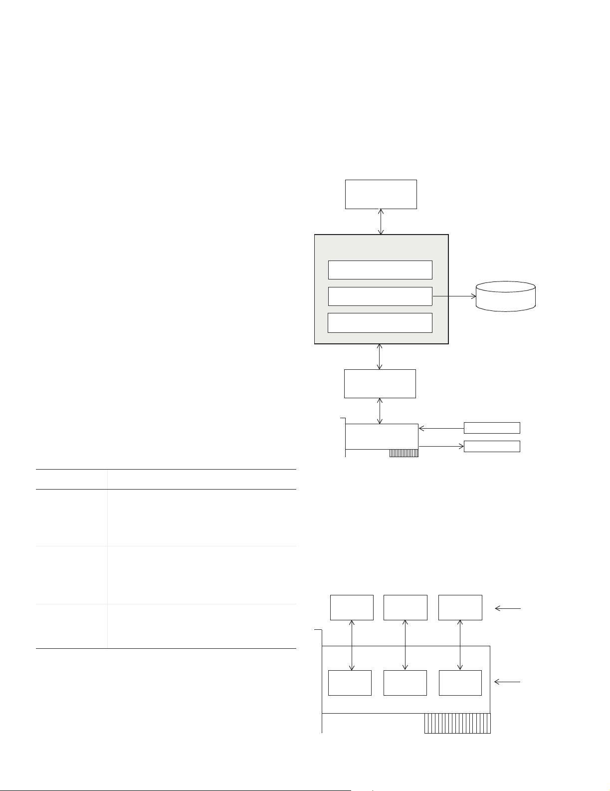
Toolbox Components
The Data Acquisition Toolbox™ components are
described below.
These components are shown below.
MATLAB
Data Acquisition Toolbox
M-file functions
Data acquisition engine
Hard ware driver ada ptors
Hardware driver
Hardware
®
Interactive commands and data
Properties, data, and events
Properties, data, and events
Disk file
Sensors
Actuators
Component Purpose
M-files Create device objects, acquire or
output data, configure property
values, and evaluate your acquisition
status and resources.
Engine Store device objects and their
property values, control the storage of
acquired or queued data, and control
the synchronization of events.
Adaptors Pass properties, data, and events
between the hardware and the
engine.
Device Objects
Device objects allow you to access specific hardware
subsystems. The device objects supported by the toolbox
include analog input (AI), analog output (AO), and digital
I/O (DIO) objects.
AI
object
AI
subsystem
AO
object
AO
subsystem
DIO
object
DIO
subsystem
Toolbox device
objects
Hardware
subsystems
1
Page 2
The Data Acquisition Session
A complete data acquisition session consists of five steps:
1 Creating a device object
2 Adding channels or lines to the device object
3 Configuring property values to control the behavior of
your data acquisition application
4 Acquiring data (AI) or outputting data (AO)
5 Cleaning up
Adding Channels or Lines
Before you can use a device object, you must add at least
one channel or line to it. To add channels to a device
object, you must use the
example, to add two channels to
chans = addchannel(ai,1:2);
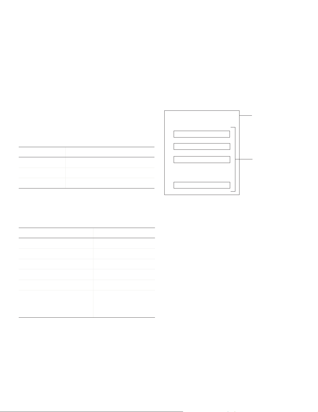
You can think of a device object as a channel or line
container, the added channels as a channel group, and
the added lines as a line group.
The relationship between an analog input object and the
channels it contains is shown below.
Analog Input Object
addchannel function. For
ai:
Creating a Device Object
To create a device object, you must call the appropriate
creation function (constructor). As shown below, creation
functions are named for the device object they create.
Subsystem Type Creation Function
Analog input
Analog output
Digital I/O
ID is the hardware device identifier. This is an optional
argument for sound cards with an
name of the hardware driver adaptor. The supported
adaptors are shown below.
Hardware Vendor Adaptor Name
Advantech
®
Measurement Computing™ mcc
National Instruments
Parallel port
Microsoft® Windows®
sound cards
analoginput('adaptor',ID);
analogoutput('adaptor',ID);
digitalio('adaptor',ID);
ID of 0. adaptor is the
advantech
®
nidaq
parallel
winsound
Container
(device object)
Channel 1
Channel 2
Channel 3
.
.
.
Channel n
Channel group
For digital I/O objects, this diagram looks the same
except that lines replace channels.
Configuring Properties
You can control the behavior of your data acquisition
application by configuring properties. The rules
associated with configuring properties include
• Property names are not case sensitive.
• You can abbreviate property names.
•
set(ai) returns all settable properties for ai, while
set(ai.Channel(index)) returns all settable
properties for the specified channel.
•
get(ai) returns the current property values for ai,
while
get(ai.Channel(index)) returns the current
property values for the specified channel.
For example, to create the analog input object
sound card:
ai = analoginput('winsound');
ai for a
2
Page 3

Property Types
Toolbox properties are divided into these two main types:
• Common properties that apply to every channel or line
contained by a device object
• Channel/line properties that you can configure for
individual channels or lines
Common and channel/line properties are divided into
these two types:
• Base properties that apply to all supported hardware
subsystems of a given type (AI, AO, DIO)
• Device-specific properties that apply to the specific
hardware you are using
set and get display the base properties followed by the
device-specific properties.
Issuing a Trigger
To log data to the engine or a disk file (AI), or to output
data from the engine (AO), a trigger must occur. The
trigger types supported for all hardware are given below.
Trigger Type Description
Immediate
Manual The trigger occurs after you manually
Software
(AI only)
The trigger occurs just after you issue
start. This is the default trigger type.
issue the
trigger function.
The trigger occurs when a signal
satisfying the specified condition is
detected. You must specify a channel
as a trigger source.
Property Syntax
You can configure and return property values three
ways: the
get or set functions, dot notation, or named
indexing.
The
get and set syntax is similar to the Handle
Graphics®
out = get(ai,'SampleRate');
set(ai,'SampleRate',11025)
get and set syntax.
The dot notation has the following syntax:
out = ai.SampleRate;
ai.SampleRate = 11025;
Named indexing allows you to associate a descriptive
name with a channel or line. For example, to associate
the name
set(ai.Channel(1),'ChannelName','Chan1');
out = ai.Chan1.UnitsRange;
ai.Chan1.UnitsRange = [0 10];
Chan1 with the first channel contained by ai:
Acquiring or Outputting Data
To acquire (AI) or output (AO) data, you must
1 Start the device object.
2 Log or send data.
3 Stop the device object.
After the trigger occurs, the
property is automatically set to
Logging (AI) or Sending (AO)
On.
Stopping a Device Object
A device object stops when the requested data is acquired
(AI) or output (AO), a run-time error occurs, or you issue
the
stop function.
stop(ai)
Managing Data
Previewing Data
While an AI object is running, you can preview acquired
data with the
1000 samples for
out = peekdata(ai,1000);
peekdata
MATLAB® and does not extract data from the engine.
Extracting Data
At any time after data is acquired by an AI object, you can
extract it from the engine with the
example, to extract 1000 samples for
out = getdata(ai,1000);
getdata
when all requested samples are returned.
peekdata function. For example, to preview
ai:
returns execution control immediately to
getdata function. For
ai:
returns execution control to MATLAB only
Starting the Device Object
To start the device object, use the start function.
start(ai)
After the device object is started, the Running (AI) or
Sending (AO) property is automatically set to On.
Outputting Data
To output data, you must first queue it in the engine with
the
putdata function. For example, to queue 1000
samples for the analog output object
putdata(ao,[1:1000]')
Once data is queued, you can start the AO object.
3
ao:
Page 4

Reading and Writing Digital Values
Transferring digital values to and from a DIO subsystem
is not clocked at a specific rate in the way that data is
sampled by an analog input subsystem. Instead, values
are either written directly to digital lines with
or read directly from digital lines with
getvalue.
putvalue,
Additionally, DIO objects do not store data in the engine.
Therefore, they do not require starting or triggering. For
example, to write the value 23 to eight DIO lines:
dio = digitalio('nidaq','Dev1');
addline(dio,0:7,'out');
data = 23;
putvalue(dio,data)
getvalue(dio)
Events and Callbacks
An event occurs at a particular time after a condition is
met. Unless an error occurs, all AI and AO data
acquisition sessions contain a start, trigger, and stop
event.
You can access event information with the
property:
EventLog
Deleting and Clearing Device Objects
The delete function removes the specified device object
from the engine but not from the MATLAB® workspace.
delete(ai)
ai
still exists in the MATLAB workspace, but is an
invalid object since it is no longer associated with
hardware. You should remove invalid device objects with
the
clear command.
clear ai
If you clear a valid device object, the object no longer
exists in the workspace, but does exist in the engine. You
can return device objects from the engine with the
daqfind function.
out = daqfind;
ai = out(1);
Saving and Loading Device Objects
You can save a device object to a MAT-file with the save
command.
save ai
Events = ai.EventLog;
EventTypes = {Events.Type}
EventTypes =
'Start' 'Trigger' 'Stop'
When an event occurs, you can execute an M-file callback
function. You can select the callback function to be
executed by specifying the name of the M-file as the value
for the associated callback property.
For example, the following commands configure
that the M-file
daqcallback is executed when a trigger,
ai so
run-time error, or stop event occurs.
set(ai,'TriggerFcn',@daqcallback)
set(ai,'RuntimeErrorFcn',@daqcallback)
set(ai,'StopFcn',@daqcallback)
To see how you construct a callback function, type
type daqcallback
You can load a device object into the MATLAB®
workspace with the
load ai
load command.
You can convert a device object to equivalent MATLAB
code with the
obj2code(ai,'ai_save')
obj2code function.
You can recreate the device object by running the M-file.
ai = ai_save
Logging Information to Disk
For an AI object, you can log acquired data, events, device
objects, and hardware information to a disk file using
these properties.
set(ai,'LoggingMode','Disk&Memory')
set(ai,'LogFileName','data.daq')
set(ai,'LogToDiskMode','Index')
You can retrieve information from an existing log file
using the
daqread function. To retrieve all logged data:
data = daqread('data.daq');
To retrieve only object and hardware information:
daqinfo = daqread('data.daq','info');
4
Page 5

Getting Information and Help
You can obtain information or help about installed
hardware, driver adaptors, device objects, functions, or
properties using the functions shown below.
Function Description
daqhelp
Display help for device objects,
constructors, adaptors, functions, and
properties.
daqhwinfo Display data acquisition hardware
information.
propinfo Return property characteristics for
device objects, channels, or lines.
PDF and HTML versions of the Data Acquisition
Toolbox™ User’s Guide are available through the Help
browser.
5
Page 6

Functions
Toolbox functions and the device objects they are associated with are organized into the groups shown below. The
supported device objects include analog input (AI), analog output (AO), and digital I/O (DIO).
Creating Device Objects AI AO DIO
analoginput
analogoutput Create an analog output object. 3
digitalio Create a digital I/O object. 3
Adding Channels and Lines AI AO DIO
addchannel
addline Add hardware lines to a digital I/O object. 3
Getting and Setting Properties AI AO DIO
get
set Configure or display device object properties. 333
setverify Configure and return the specified property. 333
Create an analog input object. 3
Add hardware channels to an analog input or analog output object. 33
Return device object properties. 333
Executing the Object AI AO DIO
start
stop Stop a device object. 333
trigger Manually execute a trigger. 33
wait Wait for the device object to stop running. 33
Working with Data AI AO DIO
flushdata
getdata Extract data, time, and event information from the data acquisition engine. 3
getsample Immediately acquire one sample. 3
getvalue Read values from lines. 3
peekdata Preview most recent acquired data. 3
putdata Queue data in the engine for eventual output. 3
Start a device object. 333
Remove data from the data acquisition engine. 3
6
Page 7

Working with Data AI AO DIO
putsample Immediately output one sample. 3
putvalue Write values to lines. 3
Getting Information and Help AI AO DIO
daqhelp
Display help for device objects, constructors, adaptors, functions, and
333
properties.
daqhwinfo Display data acquisition hardware information. 333
propinfo Return property characteristics for device objects, channels, or lines. 333
General Purpose AI AO DIO
binvec2dec
clear Remove device objects from the MATLAB
daqcallback A callback function that displays event information for the specified event. 333
daqfind Return device objects, channels, or lines from the data acquisition engine
Convert binary vector to decimal value. 3
®
workspace. 333
333
to the MATLAB workspace.
daqmem Allocate or display memory resources. 33
daqread Read a Data Acquisition Toolbox™ (.daq) file. 3
daqregister Register or unregister a hardware driver adaptor. 333
daqreset Remove device objects and data acquisition DLLs from memory. 333
dec2binvec Convert decimal value to binary vector. 3
delete Remove device objects, channels, or lines from the data acquisition engine. 333
disp Display summary information for device objects, channels, or lines. 333
ischannel Check for channels. 333
isdioline Check for lines. 333
isvalid Determine whether device objects, channels, or lines are valid. 333
length Return the length of a device object, channel group, or line group. 333
load Load device objects, channels, or lines into the MATLAB workspace. 333
makenames Generate a list of descriptive channel or line names. 333
obj2mfile Convert device objects, channels, or lines to MATLAB code. 333
save Save device objects to a MAT-file. 333
showdaqevents Display event log information. 33
size Return the size of a device object, channel group, or line group. 333
7
Page 8

Analog Input Base Properties
A
nalog input base properties are divided into two main categories: common properties and channel properties.
Common properties apply to every channel contained by the analog input object, while channel properties can be
configured for individual channels.
Common Properties
Analog Input Basic Setup Properties
SamplesPerTrigger
Specify the number of samples to acquire for each channel group member for each
trigger that occurs.
SampleRate Specify the per-channel rate at which analog data is converted to digital data.
TriggerType Specify the type of trigger to execute.
Analog Input Logging Properties
LogFileName
Logging Indicate whether data is being logged to memory or to a disk file.
LoggingMode Specify the destination for acquired data.
LogToDiskMode Specify whether data, events, and hardware information are saved to one disk file or to
Specify the name of the disk file to which information is logged.
multiple disk files.
Analog Input Trigger Properties
InitialTriggerTime
Indicate the absolute time of the first trigger.
ManualTriggerHwOn Specify that the hardware device starts when a manual trigger is issued.
TriggerFcn Specify the M-file callback function to execute when a trigger occurs.
TriggerChannel Specify the channel serving as a trigger source.
TriggerCondition Specify the condition that must be satisfied before a trigger executes.
TriggerCondition
Value
TriggerDelay Specify the delay value for data logging.
TriggerDelayUnits Specify the units in which trigger delay data is measured.
TriggerRepeat Specify the number of additional times the trigger executes.
TriggersExecuted Indicate the number of triggers that execute.
TriggerType Specify the type of trigger to execute.
Specify one or more voltage values that must be satisfied before a trigger executes.
8
Page 9

Analog Input Status Properties
Logging
Running Indicate whether the device object is running.
SamplesAcquired Indicate the number of samples acquired per channel.
SamplesAvailable Indicate the number of samples available per channel in the engine.
Analog Input Hardware Configuration Properties
ChannelSkew
ChannelSkewMode Specify how the channel skew is determined.
ClockSource Specify the clock used to govern the hardware conversion rate.
InputType Specify the analog input hardware channel configuration.
SampleRate Specify the per-channel rate at which analog data is converted to digital data.
Analog Input Callback Properties
Indicate whether data is being logged to memory or to a disk file.
Specify the time between consecutive scanned hardware channels.
DataMissedFcn
InputOverRangeFcn Specify the M-file callback function to execute when acquired data exceeds the valid
Specify the M-file callback function to execute when data is missed.
hardware range.
RuntimeErrorFcn Specify the M-file callback function to execute when a run-time error occurs.
SamplesAcquiredFcn Specify the M-file callback function to execute every time a predefined number of
samples is acquired for each channel group member.
SamplesAcquired
FcnCount
StartFcn Specify the M-file callback function to execute just before the device object starts
Specify the number of samples to acquire for each channel group member before a
samples acquired event is generated.
running.
StopFcn Specify the M-file callback function to execute just after the device object stops running.
TimerFcn Specify the M-file callback function to execute whenever a predefined period of time
passes.
TimerPeriod Specify the period of time between timer events.
TriggerFcn Specify the M-file callback function to execute when a trigger occurs.
9
Page 10

Analog Input General Purpose Properties
BufferingConfig
BufferingMode Specify how memory is allocated.
Channel Contain hardware channels added to the device object.
EventLog Store information for specific events.
Name Specify a descriptive name for the device object.
Tag Specify a device object label.
Timeout Specify an additional waiting time to extract data.
Type Indicate the device object type.
UserData Store data that you want to associate with a device object.
Specify the per-channel allocated memory.
Channel Properties
Analog Input Channel Properties
ChannelName
HwChannel Specify the hardware channel ID.
Specify a descriptive channel name.
Index Indicate the MATLAB
InputRange Specify the range of the analog input subsystem.
NativeOffset Indicate the offset to use when converting between the native data format and doubles.
NativeScaling Indicate the scaling to use when converting between the native data format and doubles.
Parent Indicate the parent (device object) of a channel.
SensorRange Specify the range of data you expect from your sensor.
Type Indicate a channel.
Units Specify the engineering units label.
UnitsRange Specify the range of data as engineering units.
®
index of a hardware channel.
10
Page 11

Analog Output Base Properties
A
nalog output base properties are divided into two main categories: common properties and channel properties.
Common properties apply to every channel contained by the analog output object, while channel properties can be
configured for individual channels.
Common Properties
Analog Output Basic Setup Properties
SampleRate
TriggerType Specify the type of trigger to execute.
Analog Output Trigger Properties
InitialTriggerTime
TriggerFcn Specify the M-file callback function to execute when a trigger occurs.
TriggersExecuted Indicate the number of triggers that execute.
TriggerType Specify the type of trigger to execute.
Analog Output Status Properties
Running
SamplesAvailable Indicate the number of samples available per channel in the engine.
SamplesOutput Indicate the number of samples output per channel from the engine.
Specify the per-channel rate at which digital data is converted to analog data.
Indicate the absolute time of the first trigger.
Indicate whether the device object is running.
Sending Indicate whether data is being sent to the hardware device.
Analog Output Hardware Configuration Properties
ClockSource
SampleRate Specify the per-channel rate at which digital data is converted to analog data.
Analog Output Data Management Properties
MaxSamplesQueued
RepeatOutput Specify the number of additional times queued data is output.
Timeout Specify an additional waiting time to queue data.
Specify the clock used to govern the hardware conversion rate.
Indicate the maximum number of samples that can be queued in the engine.
11
Page 12

Analog Output Callback Properties
RuntimeErrorFcn
SamplesOutputFcn Specify the M-file callback function to execute every time a predefined number of
Specify the M-file callback function to execute when a run-time error occurs.
samples is output for each channel group member.
SamplesOutput
FcnCount
StartFcn Specify the M-file callback function to execute just before the device object starts
Specify the number of samples to output for each channel group member before a
samples output event is generated.
running.
StopFcn Specify the M-file callback function to execute just after the device object stops running.
TimerFcn Specify the M-file callback function to execute whenever a predefined period of time
passes.
TimerPeriod Specify the period of time between timer events.
TriggerFcn Specify the M-file callback function to execute when a trigger occurs.
Analog Output General Purpose Properties
BufferingConfig
BufferingMode Specify how memory is allocated.
Specify the per-channel allocated memory.
Channel Contain hardware channels added to the device object.
EventLog Store information for specific events.
Name Specify a descriptive name for the device object.
OutOfDataMode Specify how the value held by the analog output subsystem is determined.
Tag Specify a device object label.
Type Indicate the device object type.
UserData Store data that you want to associate with a device object.
12
Page 13

Channel Properties
Analog Output Channel Properties
ChannelName
DefaultChannel
Value
HwChannel Specify the hardware channel ID.
Index Indicate the MATLAB
NativeOffset Indicate the offset to use when converting between the native data format and doubles.
NativeScaling Indicate the scaling to use when converting between the native data format and doubles.
OutputRange Specify the range of the analog output hardware subsystem.
Parent Indicate the parent (device object) of a channel.
Type Indicate a channel.
Units Specify the engineering units label.
UnitsRange Specify the range of data as engineering units.
Specify a descriptive channel name.
Specify the value held by the analog output subsystem.
®
index of a hardware channel.
13
Page 14

Digital I/O Base Properties
Digital I/O base properties are divided into two main categories: common properties and line properties. Common
properties apply to every line contained by the digital I/O object, while line properties can be configured for individual
lines.
Common Properties
Digital I/O Common Properties
Line
Name Specify a descriptive name for the device object.
Running Indicate whether the device object is running.
Tag Specify a device object label.
TimerFcn Specify the M-file callback function to execute whenever a predefined period of time
Contain hardware lines added to the device object.
passes.
TimerPeriod Specify the period of time between timer events.
Type Indicate the device object type.
UserData Store data that you want to associate with a device object.
Line Properties
Digital I/O Line Properties
Direction
HwLine Specify the hardware line ID.
Index Indicate the MATLAB
Specify whether a line is used for input or output.
®
index of a hardware line.
LineName Specify a descriptive line name.
Parent Indicate the parent (device object) of a line.
Port Specify the port ID.
Type Indicate a line.
COPYRIGHT 1999 - 2008 by The MathWorks, Inc. MATLAB and Simulink are registered trademarks of The MathWorks, Inc. See
www.mathworks.com/trademarks for a list of additional trademarks. Other product or brand names may be trademarks or registered
trademarks of their respective holders.
The MathWorks products are protected by one or more U.S. patents. Please see www.mathworks.com/patents for more information.
14
 Loading...