


Communications Bl
Reference
ockset™ 4

How to Contact The MathWorks
www.mathworks.
comp.soft-sys.matlab Newsgroup
www.mathworks.com/contact_TS.html T echnical Support
suggest@mathworks.com Product enhancement suggestions
bugs@mathwo
doc@mathworks.com Documentation error reports
service@mathworks.com Order status, license renewals, passcodes
info@mathwo
com
rks.com
rks.com
Web
Bug reports
Sales, prici
ng, and general information
508-647-7000 (Phone)
508-647-7001 (Fax)
The MathWorks, Inc.
3 Apple Hill Drive
Natick, MA 01760-2098
For contact information about worldwide offices, see the MathWorks Web site.
Communications Blockset™ Reference
© COPYRIGHT 2001–20 10 by The MathWorks, Inc.
The software described in this document is furnished under a license agreement. The software may be used
or copied only under the terms of the license agreement. No part of this manual may be photocopied or
reproduced in any form without prior written consent from The MathW orks, Inc.
FEDERAL ACQUISITION: This provision applies to all acquisitions of the Program and Documentation
by, for, or through the federal government of the United States. By accepting delivery of the Program
or Documentation, the government hereby agrees that this software or documentation qualifies as
commercial computer software or commercial computer software documentation as such terms are used
or defined in FAR 12.212, DFARS Part 227.72, and DFARS 252.227-7014. Accordingly, the terms and
conditions of this Agreement and only those rights specified in this Agreement, shall pertain to and govern
theuse,modification,reproduction,release,performance,display,anddisclosureoftheProgramand
Documentation by the federal government (or other entity acquiring for or through the federal government)
and shall supersede any conflicting contractual terms or conditions. If this License fails to meet the
government’s needs or is inconsistent in any respect with federal procurement law, the government agrees
to return the Program and Docu mentation, unused, to The MathWorks, Inc.
Trademarks
MATLAB and Simulink are registered trademarks of The MathWorks, Inc. See
www.mathworks.com/trademarks for a list of additional trademarks. Other product or brand
names may be trademarks or registered trademarks of their respective holders.
Patents
The MathWorks products are protected by one or more U.S. patents. Please see
www.mathworks.com/patents for more information.

Revision History
May 2001 Online only New for Version 2.0.1 (Release 12.1)
July 2002 Online only Revised for Version 2.5 (Release 13)
June 2004 Online only Revised for Version 3.0 (Release 14)
October 2004 Online only Revised for Version 3.0.1 (Release 14SP1)
March 2005 Online only Revised for Version 3.1 (Release 14SP2)
September 2005 Online only Revised for Version 3.2 (Release 14SP3)
March 2006 Online only Revised for Version 3.3 (Release 2006a)
September 2006 Online only Revised for Version 3.4 (Release 2006b)
March 2007 Online only Revised for Version 3.5 (Release 2007a)
September 2007 Online only Revised for Version 3.6 (Release 2007b)
March 2008 Online only Revised for Version 4.0 (Release 2008a)
October 2008 Online only Revised for Version 4.1 (Release 2008b)
March 2009 Online only Revised for Version 4.2 (Release 2009a)
September 2009 Online only Revised for Version 4.3 (Release 2009b)
March 2010 Online only Revised for Version 4.4 (Release 2010a)


Block Reference
1
Communications Sources ........................... 1-2
Random Data Sources
Noise G enerators
Sequence Generators
.............................. 1-2
.................................. 1-2
.............................. 1-2
Contents
Communications Sinks
Source Coding
Error Detection and Correction
Block Coding
Convolutional Coding
Cyclic Redundancy Check Coding
Interleaving
Block Interleaving
Convolutional Interleaving
MIMO
Modulation
Digital Baseband AM Sublibrary
Digital Baseband PM Sublibrary
Digital Baseband FM Sublibrary
Digital Baseband CPM Sublibrary
Digital Baseband TCM Sublibrary
Analog Pa ssb an d Modulation
............................................ 1-8
..................................... 1-3
..................................... 1-4
....................................... 1-6
....................................... 1-8
............................. 1-3
.............................. 1-5
................................. 1-6
.......................... 1-7
........................ 1-11
..................... 1-4
.................... 1-6
..................... 1-8
..................... 1-9
..................... 1-10
.................... 1-10
.................... 1-11
Communications F ilters
Channels
.......................................... 1-12
............................ 1-12
v

RF Impairments ................................... 1-13
Synchronization
Carrier Phase Recovery
Timing Phase Recovery
Synchronization Components
Equalizers
Sequence Operations
Utility Blocks
2
3
................................... 1-13
............................ 1-14
............................. 1-14
........................ 1-14
........................................ 1-15
.............................. 1-16
..................................... 1-17
Blocks — Alphabetical List
Function Reference
vi Contents
Algorithm Used to Decode BCH and
Reed-Solomon Codes
A
Errors-only Decoding .............................. A-2
Errors and Erasures Decoding
References
........................................ A-4
...................... A-3

Index
vii

viii Contents

Block Reference
Communications Sources (p. 1-2) Sources of random and nonrandom
1
data
Communications Sinks (p. 1-3)
Source Coding (p. 1-3) Quantization, companding, and
Error Detection and Correction
(p. 1-4)
Interleaving (p. 1-6)
MIMO (p. 1-8) Multiple Input Multiple Output
Modulation (p. 1-8)
Communications Filters (p. 1-12)
Channels (p. 1-12)
RF Impairments (p. 1-13)
Synchronization (p. 1-13)
Equalizers (p. 1-15) Adaptive and MLSE equalizers
Sequence Operations (p. 1-16) Scrambling, puncturing, and other
Error statistics and plotting
differential coding
Block, convolutional, and CRC
coding
Block and convolutional interleaving
blocks
Digital baseban d and analog
passband modulation
Filtering a nd pulse shaping
Modeling channel impairments
Modeling impairments caused by the
radio frequency components
Phase recovery methods and
phase-locked loops
operations on sequences
Utility Blocks (p. 1-17)
Miscellaneous relevant blocks

1 Block Reference
Communications Sources
These are the sublibraries of Communications Sources:
Random Data Sources (p. 1-2)
Noise Generators (p. 1-2)
Sequence Generators (p. 1-2)
Random Data Sources
Bernoulli Binary Generator Generate Bernoulli-distributed
Poisson Integer Generator Generate Poisson-distributed
Random Integer Generator Generate integers randomly
random binary numbers
random integers
distributed in range [0, M-1]
1-2
Noise Generators
Gaussian Noise Generator Generate Gaussian distributed noise
with given mean and variance values
Rayleigh Noise Generator Generate Rayleigh distributed noise
Rician Noise Generator Generate Rician distributed noise
Uniform Noise Generator Generate uniformly distributed noise
between upper and lower bounds
Sequence Generators
Barker Code Generator Generate Barker Code
Gold Sequence Generator Generate Gold sequence from set of
sequences

Hadamard Code Generator Generate Hadamard code from
Kasami Se quence Generator Generate Kasami sequence from set
OVSF Code Generator Generate orthogonal variable
PN Sequence Generator Generate pseudonoise sequence
Walsh Code Generator Generate Walsh code from
Communications Sinks
Discrete-Time Eye Diagram Scope Display multiple traces of modulated
Communications Sinks
orthogonal set of codes
of Kasami sequences
spreading factor (OVSF) code from
set of orthogonal codes
orthogonal set of codes
signal
Discrete-Time Scatter Plot Scope
Discrete-Time Signal Trajectory
Scope
Error Rate Calculation Compute bit error rate or symbol
Source Coding
A-Law Compressor Implement A-law compressor for
A-Law Expander Implement A-law expander for
Display in-phase a nd quadrature
components of modulated signal
constellation
Plot modulated signal’s in-pha s e
component versus its quadrature
component
error rate of input data
source coding
source coding
1-3

1 Block Reference
Differential Decoder
Differential Encoder
Mu-Law Compressor Implement µ-law compressor for
Mu-Law Expander
Quantizing Decoder
Quantizing Encoder Quantize signal using partition and
Error Detection and Correction
ThesearethesublibrariesofError Detection and Correction:
Block Coding (p. 1-4)
Convolutional Coding (p. 1-5)
Decode binary signal using
differential coding
Encode binary s ignal using
differential coding
source coding
Implement µ-law expander for
source coding
Decode quantization index according
to codebook
codebook
1-4
Cyclic Redundancy Check Coding
(p. 1-6)
Block Coding
BCH Decoder Decode BCH code to recover binary
vector data
BCH Encoder Create BCH code from binary vector
data
Binary Cyclic Decoder
Decode systematic cyclic code to
recover binary vector data

Error Detection and Correction
Binary Cyclic Encoder Create systematic cyclic code from
binary vector data
Binary Linear Decoder Decode linear block code to recover
binary vector data
Binary Linear Encoder
Binary-Input RS Encoder Create Reed-Solomon code from
Binary-Output RS Decoder Decode Reed-Solomon code to recover
Hamming Decoder Decode Hamming code to recover
Hamming Encoder
Integer-Input RS Encoder Create Reed-So lomon code from
Integer-Output RS Decoder Decode Reed-Solomon code to recover
LDPC Decoder
LDPC Encoder
Create linear block code from binary
vector data
binary vector data
binary vector data
binary vector data
Create Hamming code from binary
vector data
integer vector data
integer vector data
Decode binary low-density
parity-check code specified by
parity-check matrix
Encode binary low-density
parity-check code specified by
parity-check matrix
Convolutional Coding
APP Decoder
Convolutional E ncoder Create convolutional code from
Viterbi Decoder Decode convolutionally encoded data
Decode convolutional code using a
posteriori probability (APP) method
binary data
using Viterbi al gorithm
1-5

1 Block Reference
Interleaving
Cyclic Redundan
CRC-N Generator Generate CRC bits according to CRC
CRC-N Syndrome Detector Detect errors in input data frames
General CRC Generator Generate CRC bits according to
General CRC Syndrome Detector Detect errors in input data frames
These are the sublibraries of Interleaving:
Block In
Convolu
terleaving (p. 1-6)
tional Interleaving (p. 1-7)
cy Check Coding
methodandappendtoinputdata
frames
according to selected CR C method
generator polynomial and append to
input data frames
according to generator polynomial
1-6
Block Interleaving
raic Deinterleaver
Algeb
braic Interleaver
Alge
General Block Deinterleaver Restore ordering of symbols in input
General B lock Interleaver
re ordering of input symbols
Resto
algebraically derived
using
tation
permu
Reorder input symbols using
algebraically derived permutation
table
vector
Reorder symbols in input vector

Interleaving
Matrix Deinterleaver
Matrix Helical Scan Deinterleaver Restore ordering of input symbols by
Matrix Helical Scan Interleaver
Matrix Interleaver
Random Deinterleaver
Random Interleaver Reorder input symbols using random
Permute input symbols by filling
matrix by columns and emptying it
by rows
filling matrix alon g diagonals
Permute input symbols by selecting
matrix elements along diag onals
Permute input symbols by filling
matrix by rows and emptying it by
columns
Restore ordering of input symbols
using random permutation
permutation
Convolutional Interleaving
Convolutional Deinterleaver Restore ordering of symbols that
were permuted using shift registers
Convolutional Interleaver Permute input symbols using set of
shift registers
General Multiplexed Deinterleaver Restore ordering of symbo ls using
specified-delay shift regi sters
General Multiplex ed Interleaver Permute input sy mbols using set of
shift re gi sters with specified delays
Helical Deinterleaver
Helical Interleaver Permute input symbols using helical
Restore ordering of symbols
permuted by helical interleaver
array
1-7

1 Block Reference
MIMO
OSTBC Combiner Combine inputs for received signals
and channel estimate according to
orthogonal space-time block code
(OSTBC)
Modulation
OSTBC Encoder
These are the sublibraries of Modulation:
Digital Baseband AM Sublibrary
(p. 1-8)
Digital Baseband PM Sublibrary
(p. 1-9)
Digital Baseband FM Sublibrary
(p. 1-10)
Digital Baseband CPM Sublibrary
(p. 1-10)
Digital Baseband TCM Sublibrary
(p. 1-11)
Analog Passband Modulation
(p. 1-11)
Encode input message using
orthogonal space-time block code
(OSTBC)
1-8
Digital Baseband AM Sublibrary
General Q AM De modulator
Baseband
General QAM Modulator Baseband
Demodulate QAM-modulated data
Modulate using quadrature
amplitude modulation

M-PAM D emodulator Baseband Demodulate PAM-modulated data
Modulation
M-PAM Modulator Baseband
Rectangular QAM Demodulator
Baseband
Rectangular QAM Modulator
Baseband
Modulate using M-ary pulse
amplitude modulation
Demodulate
rectangular-QAM-modulated data
Modulate using rectangular
quadrature amplitude modulation
Digital Baseband PM Sublibrary
BPSK Demodulator Baseband Demodulate BPSK-modulated data
BPSK Modulator Baseband Modulate using binary phase shift
keying method
DBPSK D emodulator Baseband Demodulate DBPSK-modulated data
DBPSK Modulator Baseband Modulate using differential binary
phase shift keying method
DQPSK Demodulator Baseband Demodulate DQPSK-modulated
data
DQPSK M odulator Baseband Modulate using differential
quaternary phase shift keying
method
M-DPSK Demodulator Baseband Demodulate D PSK-modulated data
M-DPSK M odulator Baseband Modulate using M-ary differential
phase shift keying method
M-PSK Demodulator Baseband Demodulate PSK-modulated data
M-PSK Modulator Baseband Modulate using M-ary phase shift
keying method
OQPSK Demodulator Baseband Demodulate OQPSK-modulated
data
OQPSK M odulator Baseband Modulate using offset quadrature
phase shift keying method
1-9

1 Block Reference
QPSK Dem odulator Baseband Demodulate QPSK-modulated data
QPSK Modulator Baseband
Modulate using quaternary phase
shift keying method
Digital Baseband F M Sublibrary
M-FSK Demodulator Baseband Demodulate FSK-modulated data
M-FSK M odulator Baseband Modulate using M-ary frequency
shift keying method
Digital Baseband CPM Sublibrary
CPFSK Demodulator Baseband Demodulate CPFSK-modulated data
CPFSK Modulator Baseband
CPM Demodulator Baseband Demodulate CPM-modulated data
CPM Modulator Baseband
GMSK Demodulator Baseband Demodulate GMSK-modulated data
GMSK Modulator Baseband Modulate using Gaussian minimum
Modulate using continuous phase
frequency shift keying method
Modulate using continuous phase
modulation
shift keying method
1-10
MSK D emodulator Baseband Demodulate MSK-modulated data
MSK Modulator Ba seb an d Modulate using minimum shift
keying method

Modulation
Digital Baseban
General TCM Decoder
General TCM En
M-PSK TCM Dec
M-PSK TCM Encoder Convolutionally encode binary data
Rectangular QA M TCM Decoder
Rectangular QAM TCM Encoder Convolutionally encode binary data
Analog
DSB AM Demodulator Passband Demodulate DSB-AM-modulated
Passband Modulation
dTCMSublibrary
coder
oder
Decode trellisdata, mapped us
constellation
Convolutiona
data and map us
constellati
Decode trellis-coded modulation
data, modulated using PSK method
and modulate using PSK method
Decode trellis-coded modulation
data, modulated using QAM method
and modulate using QAM method
data
coded modulation
ing arbitrary
lly encode binary
ing arbitrary
on
late using double-sideband
DSB AM Modulator Passband
SC AM Demodulator Passband
DSB
SC AM Modulator Passband
DSB
FM Demodulator Passband Demodulate FM-modulated data
FM Modulator Passband
PM Demodulator Passband Demodulate PM-modulated data
PM Modulator Passband Modulate using phase modulation
Modu
itude modulation
ampl
odulate DSBSC-AM-modulated
Dem
a
dat
Modulate using double-sideban d
suppressed-carrier amplitude
modulation
Modulate using frequency
modulation
1-11

1 Block Reference
SSB AM Demodulator Passband Demodulate SSB-AM-modulated
data
SSB AM Modulator Passband
Communications Filters
Gaussian Filter
Ideal Rectangular Pulse Filter
Integrate and Dump Integrate discrete-time signal,
Raised Cosine Receive Filter
Raised Cosine Transmit Filter Upsample and filter input signal
Windowed Integrator
Modulate using single-sideband
amplitude modulation
Filter input signal, possibly
downsampling, using Gaussian FIR
filter
Shape input signal using ideal
rectangular pulses
resettingtozeroperiodically
Filter input signal, possibly
downsampling, using raised cosine
FIR filter
using raised cosine FIR filter
Integrateovertimewindowoffixed
length
Channels
1-12
AWGN Channel Add white Gaussian noise to input
signal
Binary Symmetric Channel
Introduce binary errors

Multipath Rayleigh Fading Channel Simulate multipath Rayleigh fading
Multipath Rician Fading Channel Simulate multipath Rician fading
RF Impairments
Free Space Path Loss Reduce amplitude of input signal by
I/Q Imbalance Create complex baseband m odel
RF Impairments
propagation channel
propagation channel
amount specified
of signal impairments caused by
imbalances between in-phase and
quadrature receiv er components
Memoryless Nonlinearity
Phase Noise
Phase/Frequency Offset Apply phase and frequency offsets to
Receiver Thermal Noise
Synchronization
These are the sublibraries of Synchronization:
Carrier Phase Recovery (p. 1-14)
Timing Phase Recovery (p. 1-14)
Synchronization Components
(p. 1-14)
Apply memoryless nonlinearity to
complex baseband signal
Apply receiver phase noise to
complex baseband signal
complex baseband signal
Apply receiver thermal noise to
complex baseband signal
1-13

1 Block Reference
covery
covery
Recover carrier
2P-Power metho
Recover carrier phase using M-Pow er
method
phase using
d
Carrier Phase Re
CPM Phase Recovery
M-PSK Phase Re
Timing Phase Recover y
Early-Late Gate Timing Recovery
Gardner Timing Recovery
MSK-Type
Mueller-Muller Timing Recovery Recover symbol timing phase using
Squaring Timing Recovery
Signal Timing Recovery
Recover symbol timing phase using
early-late gate method
Recover sy
Gardner’s
Recover symbol timing phase using
fourth-order nonlinearity method
Mueller-Muller method
Recov
squar
mbol timing phase using
method
er symbol timing phase using
ing method
1-14
Synchronization Components
Baseband PLL Implement baseband phase-locked
loop
Charge Pump PLL
Continuous-Time VCO
Discrete-Time VCO
Implement charge pump
phase-locked loop using digital
phase detector
mplement voltage-controlled
I
scillator
o
Implement voltage-controlled
oscillator in discrete time

Equalizers
Equalizers
Linearized B aseband PLL
Phase-Locked Loop Impleme nt phase-locke d loop to
CMA Equalizer
LMS Decisio n Feedback E qualizer Equalize using decision feedback
LMS Linear Equalizer
MLSE Equalizer
Normalized L M S Decision Feedback
Equalizer
Implement linearized version of
baseband phase-locked loop
recover phase of input signal
Equalize using constant modulus
algorithm
equalizer that updates weights with
LMS algorithm
Equalize using linear equalizer
that updates weights with LMS
algorithm
Equalize using Viterbi algorithm
Equalize using decision feedback
equalizer that updates weights with
normalized LMS algorithm
Normalized LMS Linear Equalizer
RLS Decision Feedback Equalizer Equalize using decision feedback
RLS Linear Equalizer
Sign LMS Decision Feedback
Equalizer
Equalize using linear equalizer that
updates weights with normalized
LMS algorithm
equalizer that updates weights with
RLS algorithm
Equalize using linear equalizer
that updates weights using RLS
algorithm
Equalize using decision feedback
equalizer that updates weights with
signed LMS algorithm
1-15

1 Block Reference
Sign LMS Linear Equalizer
Variable Step LMS Decision
Feedback Equalizer
Variable Step LMS Linear Equalizer
Sequence Operations
Deinterlacer
Derepeat
Descrambler Descramble input signal
Insert Zero
Equalize using linear equalizer that
updates weights with signed LMS
algorithm
Equalize using decision feedback
equalizer that updates weights with
variable-step-size LMS algorithm
Equalize using linear equalizer
that updates weights with
variable-step-size LMS algorithm
Distribute elements of input vector
alternately between two output
vectors
Reduce sampling rate by averaging
consecutive samples
Distribute input elements in output
vector
1-16
Interlacer
Puncture
Scrambler Scramble input signal
Alternately select elements from
two input vectors to generate output
vector
Output elements which correspond
to 1s in binary Puncture vector

Utility Blocks
Utility Blocks
Align Signals Align two signals by finding delay
between them
Bipolar to Unipolar Converter
Bit to Integer Converter Map vector of bits to corre sponding
Complex Phase Difference Output phase difference between
Complex Phase Shift Shift phase of complex input signal
Data Mapper
EVM Measurement
Find De
Integ
MER Measurement
Uni
lay
er to Bit Converter
polar to Bipolar Converter
Map bipolar signal into unipolar
signal in range [0, M-1]
vector of integers
two complex input signals
by second input value
Map integer symbols from one coding
scheme to another
Calculate vector magnitude
difference between ideal reference
signal and measured signal
Find de
Map ve
bits
Meas
in di
Map unipolar signal in range [0, M-1]
into bipolar signal
lay betw een two signals
ctor of integers to vector of
ure signal-to-noise ratio (SNR)
gital modulationapplications
1-17

1 Block Reference
1-18

2
Blocks — Alphabetical List

A-Law Compressor
Purpose Implement A-law compressor for source coding
Library Source Coding
Description The A-Law Compressor block implements an A-law compressor for the
input signal. The formula for the A-law compressor is
Ax
⎧
⎪
+
1
log
⎪
y
=
⎨
VAxV
+
1
log( / )
()
⎪
⎪
1
⎩
where A is the A-law parameter of the compressor, V is the peak signal
magnitude for x, log is the natural logarithm, and sgn is the signum
function (
The most commonly used A value is 87.6.
The input can have any shape or frame status. This block processes
each vector element independently.
sign in MATLAB
xx
sgn( )
A
x
A
+
log
sgn( )
®
software).
for
for
0
V
A
V
≤≤
A
<<≤
xV
2-2
Dialog
Box
A value
The A-law parameter of the compressor.

A-Law Compressor
Peak signal m agnitude
The peak value of the input signal. This is also the peak value of
the output signal.
Supported
Data Type
Port
In
Out
Supported Data Types
• double
• double
Pair Block A-Law Expander
See Also Mu-Law Compressor
References [1] Sklar, Bernard. Digital Communications: Fundamentals and
Applications. Englewood Cliffs, N.J., Prentice-Hall, 1988.
2-3

A-Law Expander
Purpose Implement A-law e xpander for source coding
Library Source Coding
Description The A-Law Expander block recovers data that the A-Law Compressor
block compressed. The formula for the A-law expander, shown below , is
the inverse of the compressor function.
( log )
Dialog
Box
1
yA
+
⎧
⎪
A
⎪
x
=
⎨
⎪
exp ( log ) / sgn( )
⎪
⎩
The input can have any shape or frame status. This block processes
each vector element independently.
11
y for
()
AV
+−
V
y
A
for
0
y
≤≤
V
11+logA
V
1+logA
<≤
yV
2-4
A valu
Peak
e
The A-
signal magnitude
The p
utput signal.
the o
law parameter of the compressor.
eak value of the input signal. This is also the peak value of

A-Law Expander
Match these parameters to the ones in the corresponding A-Law
Compressor block.
Supported
Data Type
Port
In
Out
Supported Data Types
• double
• double
Pair Block A-Law Compressor
See Also Mu-Law Expander
References [1] Sklar, Bernard. Digital Communications: Fundamentals and
Applications. Englewood Cliffs, N.J., Prentice-Hall, 1988.
2-5

Algebraic Deinterleaver
Purpose Restore ordering of input symbols u sing algebraically derived
permutation
Library Block sublibrary of Interleaving
Description The Algebraic Deinterleaver block restores the original ordering of a
sequence that was interleaved using the Algebraic Interleaver block. In
typical usage, the parameters in thetwoblockshavethesamevalues.
The Number of elements parameter, N, indicates how many numbers
are in the input vector. If the input is frame-based, then it must be a
column vector.
The block can accept the data types
uint32, boolean, single, double,andfixed-point. Thedatatypeofthis
output will be the same as that of the input signal.
The Type parameter indicates the algebraic method that the block
uses to generate the appropri ate permutation table. Choices are
Takeshita-Costello and Welch-Costas.Eachofthesemethodshas
parameters and restrictions that are specific to it; these are described
on the reference page for the Algebraic Interleaver block.
int8, uint8, int16, uint16, int32,
2-6

Dialog
Box
Algebraic Deinterleaver
Type
The type of permutation table that the block uses for
deinterleaving. Choices are
Welch-Costas.
Number of elements
The number of elements, N, in the input vector.
Multiplicative factor
Thefactorusedtocomputethecorresponding interleaver’s
cycle vector. This field appears only if Type is set to
Takeshita-Costello.
Cyclic shift
The amount by which the block shifts indices when creating the
corresponding interleaver’s permutation table. This field appears
only if Type is set to
Takeshita-Costello.
Takeshita-Costello and
2-7

Algebraic Deinterleaver
Primitive element
An element of order N in the finite field GF(N+1). This field
appears only if Type is set to
Pair Block Algebraic Interleaver
See Also General Block Deinterleaver
References [1] Heegard, Chris and Stephe n B. Wicker. Turbo Coding.Boston:
Kluwer Academic Publishers, 1999.
[2]Takeshita,O.Y.andD.J.Costello,Jr. "NewClassesOfAlgebraic
Interleavers for Turbo-Codes." Proc. 1998 IEEE International
Symposium on Information Theory, Boston, Aug. 16-21, 1998. 419.
Welch-Costas.
2-8

Algebraic Interleaver
Purpose Reorder input symbols u sing algebraically derived permutation table
Library Block sublibrary of Interleaving
Description The Algebraic Interleaver block rearranges the elements of its input
vector using a permutation that is algebraically derived. The Number
of elements parameter, N, indicates how many numbers are in the
input vector. If the input is frame-based, then it m ust be a column
vector.
The block can accept the data types
uint32, boolean, single, double,andfixed-point. Thedatatypeofthis
output will be the same as that of the input signal.
The Type parameter indicates the algebraic method that the block
uses to generate the appropri ate permutation table. Choices are
Takeshita-Costello and Welch-Costas.Eachofthesemethodshas
parameters and restrictions that are specific to it:
• If Type is set to
Primitive element parameter is an integer, A, between 1 and N
that represents a primitive element of the finite field GF(N+1). This
means that every nonzero element of GF(N+1) can be expressed as
A raised to some integer power.
In a Welch-Costas interleaver, the permutation maps the integer k
to mod(A
• If Type is set to
integer m. The Multiplicative factor parameter, h, must be an
odd integer less than N. The Cyclic shift parameter, k, must be a
nonnegative integer less than N.
A Takeshita-Costello interleaver uses a length-N cycle vector whose
nth element is
mod(k*(n-1)*n/2, N)
k
,N+1) - 1.
Welch-Costas,thenN+1mustbeprime. The
Takeshita-Costello,thenNmustbe2
int8, uint8, int16, uint16, int32,
m
for some
for integers n between 1 and N. The block creates a permutation
vector by listing, for each element of the cycle vector in ascending
2-9

Algebraic Interleaver
order, one plus the element’s successor. The interleaver’s actual
permutation table is the result of shifting the elements of the
permutation vector left by the Cyclic shift parameter. (The block
performs all computations on numbers and indices modulo N.)
Dialog
Box
2-10
Type
Thetypeofpermutationtablethatthe block uses for interleaving.
Number of elements
The number of elements, N, in the input vector.
Multiplicative factor
The factor used to compute the interleaver’s cycle vector. This
field appears only if Type is set to
Cyclic shift
The amount by which the block shifts indices when creating
the permutation table. This field appears only if Type is set to
Takeshita-Costello.
Takeshita-Costello.

Algebraic Interleaver
Primitive element
An element of order N in the finite field GF(N+1). This field
appears only if Type is set to
Pair Block Algebraic Deinterleaver
See Also General Block Interleaver
References [1] Heegard, Chris and Stephe n B. Wicker. Turbo Coding.Boston:
Kluwer Academic Publishers, 1999.
[2]Takeshita,O.Y.andD.J.Costello,Jr. "NewClassesOfAlgebraic
Interleavers for Turbo-Codes." Proc. 1998 IEEE International
Symposium on Information Theory, Boston, Aug. 16-21, 1998. 419.
Welch-Costas.
2-11

Align Signals
Purpose Align two signals by finding delay between them
Library Utility Blocks
Description The Align Signals block aligns a signal with a delayed, and possibly
distorted, version of itself. The block is particularly useful when you
want to compare a transmitted and received signal to find the bit error
rate, but do not know the delay in the received signal.
The input port labeled
port labeled
signals must have the same sample times. The block calculates the
delay between the two signal, and then
• Delays the first signal,
through the port labeled
• Outputs the second signal
labeled
• Outputs the delay value through the port labeled
See “Computing Delays” in the Communications Blockset™ online
documentation for more information about signal delays.
The block’s Correlation window length parameter specifies
how many samples of the signals the block uses to calculate the
cross-correlation. The delay output is a nonnegative integer less than
the Correlation window length.
As the Correlation window length is increased, the reliability of
the computed delay also increases. However, the processing time to
compute the delay increases as well.
You can make the Align Signals block stop updating the delay after it
computes the same delay value for a specified number of samples. To
do so, select the Disable recurring updates check box, and enter a
positive integer in the Num ber of constant delay outputs to disable
updates field. For example, if you set Number of constant delay
outputs to disable updates to
s2 receives the delayed version of the signal. The two input
s2.
s1 receives the original signal, while the input
s1, by the calculated value, and outputs it
s1 del.
s2 without change through the port
delay.
20, the block will stop recalculating
2-12

Align Signals
and updating the delay after it calculates the same value 20 times in
succession. Disabling recurring updates causes the simulation to run
faster after the target number of constant delays occurs.
Tips for Using the Block Effectively
• Set the Correlation window length parameter sufficiently large so
that the computed delay eventually stabilizes at a constant value. If
the computed delay is not constant, you should increase Correlation
window length. If the increased value of Correlation window
length ex ceeds the duratio n of the simulation, then you should also
increase the duration of the simulation accordingly.
• If the cross-correlation between the two signals is broad, then
Correlation window length should be much larger than the
expected delay, or else the algorithm might stabilize at an incorrect
value. For example, a CPM signal has a broad autocorrelation, so
it has a broad cross-correlation with a delayed version of itself. In
this case, the Correlation window length value should be much
larger than the expected delay.
• If the block calculates a delay that is greater than 75 percent of
Correlation window length,thesignal
relative to the signal
lines leading into the two input ports.
• If you use the Align Signals block with the Error Rate Calculation
block, you should set the Receive delay parameter of the Error Rate
Calculation block to
for the delay. Also, you might want to set the Error Rate Calculation
block’s Computation delay parameter to a nonzero value to account
for the possibility that the Align Signals block takes a nonzero
amount of time to stabilize on the correct amount by which to delay
one of the signals.
s2. Inthiscase,youshouldswitchthesignal
0 because the Align Signals block compensates
s1 is probably delayed
Examples See the“Computing Delays” section of Communications Blockset User’s
Guide for an example that uses the Align Signals block in conjunction
with the Error Rate Calculation block.
2-13
Align Signals
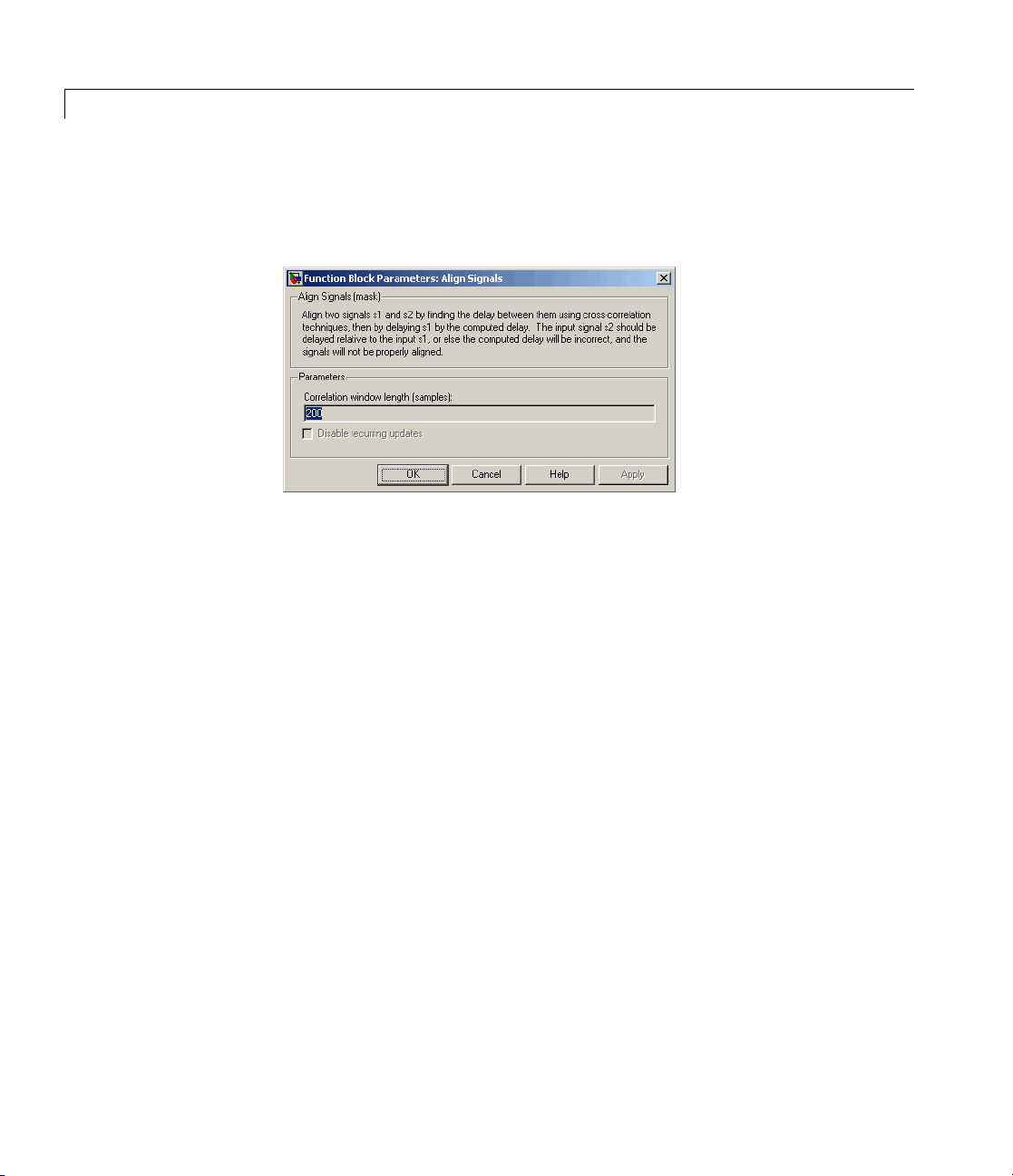
Dialog
Box
See S etting the Correlation Window Length, on the reference page for
the Find Delay block, for an example that illustrates how to set the
correlation window length properly.
Correlati
Disable r
Number o
on window length
The number
cross-co
ecurring updates
Selectin
after it
of sampl
f constant delay outputs to disable updates
Aposit
comput
appear
of samples the block uses to calculate the
rrelations of the two signals.
g this option causes the block to stop computing the delay
computes the same delay value for a specified number
es.
ive integer specifying how many times the block must
e the same delay before ceasing to update. This field
sonlyifDisable recurring updates is selected.
Algorithm The Align Signals block finds the delay by calculatin g the
cross-correlations of the first signal with time-shifted versions of the
second signal, and then finding the index at which the cross-correlation
is maximized.
See Also Find Delay, Error Rate Calculation
2-14

APP Decoder
Purpose Decode convolutional code using a posteriori probability (APP) method
Library Convolutional sublibrary of Channel Coding
Description The APP Decoder block performs a posteriori probability (APP) decoding
of a convolutional code.
Inputs and Outputs
The input L(u) represents the sequence of log-likelihoods of encoder
input bits, while th e input L(c) r epresents the sequence of log-likelihoods
of code bits. The outputs L(u) and L(c) are updated versions of these
sequences, based on information about the encoder.
If the convolutional code uses an alphabet of 2
this block’s L(c) vectors have length Q*n for some positive integer Q.
Similarly, if the decoded data uses an alphabet of 2
symbols, then this block’s L(u) vectors have length Q* k.TheintegerQ
is the number of frames that the block processes in each step.
The inputs can be either
n
possible symbols,
k
possible output
• Sample-based vectors having the same dimension and orientation,
with Q = 1
• Frame-based column vectors with any positive integer for Q
If you only need the input L(c) and output L(u), you can attach a
Simulink Ground block to the input L(u) and a Simulink Terminator
block to the output L(c).
This block accepts
however, must be of the s am e type. The output data type is the same as
the input data type.
single and double data types. Both inputs,
Specifying the Encoder
To define the convolutional encoder that produced the coded
input, use the Trellis structure parameter. This parameter is a
MATLAB structure whose format is described in “Trellis Description
2-15

APP D ecoder
of a Convolutional Encoder” in the Communications Toolbox™
documentation. You can use this parameter field in two ways:
• IfyouhaveavariableintheMATLAB workspace that contains the
trellis structure, enter its name as the Trellis structure parameter.
This way is preferable because it causes Simulink
®
to spend less time
updating the diagram at the beginning of each simulation, compared
to the usage described next.
• If you want to specify the encoder using its constraint length,
generator polynomials, and possibly feedback connection polynomials,
use a
poly2trellis command within the Trellis structure field.
For example, to use an encoder with a constraint length of 7, code
generator polynomials of 171 and 133 (in octal numbers), and a
feedback connection of 171 (in octal), set the Trellis structure
parameter to
poly2trellis(7,[171 133],171)
To indicate how the encoder treats the trellis a t the beginning and
end of each frame, set the Termination method parameter to either
Truncated or Terminated.TheTruncated option indicates that the
encoder resets to the all-zeros state at the beginning of each frame. The
Terminated option indicates that the encoder forces the trellis to end
each frame in the all-zeros state. If you use the Convolutional Encoder
block w ith the Operation mode parameter set to
every frame)
,usetheTruncated option in this block. If you use the
Truncated (reset
Convolutional Encoder block with the Operation mode parameter set
to
Terminate trellis by appending tail bits,usetheTerminated
option in this block.
2-16
Specifying Details of the Algorithm
You can control part of the decoding algorithm using the Algorithm
parameter. The
True APP option implements a posteriori probability
decoding as per equations 20–23 in section V of [1]. To gain speed, both
the
Max* and Max options approximate expressions like

APP Decoder
Dialog
Box
log exp( )a
∑
i
by other quantities. The Max option uses max(ai) as the approximation,
while the
ln( exp( ))11+−−
Max* option enables the Scaling bits parameter in the dialog box.
The
This parameter is the number of bits by which the block scales the data
it processes internally (multiplies the input by (2^
divides the pre-output by the same factor). Use this parameter to avoid
losing precision during the computations.
i
Max* option uses max(a
aa
−
ii
[3].
) plus a correction term given by
i
numScalingBits)and
Trellis structure
MATLAB structure that contains the trellis description of the
convolutional encoder.
Termination method
Either
the convolutional encoder treats the trellis at the beginning and
end of frames.
Truncated or Terminated. This parameter indicates how
2-17

APP D ecoder
Algorithm
Either
Number of scaling bits
An integer between 0 and 8 that indicates by how many bits the
decoder scales data in order to avoid losing precision. This field is
active only when Algorithm is set to
See Also Viterbi Decoder, Convolutional Encoder;poly2trellis
References [1] Benedetto, S., G. Montorsi, D. Divsalar, and F. Polla ra , “A S of t-In p ut
Soft-Output Maximum A Posterior (MAP) Module to Decode Parallel
and Serial Concatenated Codes,” JPL TDA P rogress Report, Vol. 42-127,
November 1996.
[2] Benedetto, Sergio and Guido Montorsi, “Performance of Continuous
and Blockwise Decoded Turbo Codes.” IEEE Communications Letters,
Vol. 1, May 1997, 77–79.
[3] Viterbi, Andrew J., “An Intuitive Justification and a Simplified
Implementation of the MAP Decoder for Convolutional Codes,” IEEE
Journal on Selected Areas in Communications, Vol. 16, February 1998,
260–264.
True APP, Max*,orMax.
Max*.
2-18

AWGN Channel
Purpose Add white Gaussian noise to input signal
Library Channels
Description TheAWGNChannelblockaddswhiteGaussiannoisetoarealor
complex input signal. When the input signal is real, this block adds
real Gaussian noise and produces a real output signal. When the input
signal is complex, this block adds complex Gaussian noise an d produces
a complex output signal. This block inherits its sample time from the
input signal.
This block uses the Signal Processing Blockset™ Random Source block
to generate the noise. Random numbers are generated using the
Ziggurat method, which is the same method used by the MATLAB
randn function. The Initial seed parameter in this block initializes the
noise generator. Initial seed canbeeitherascalaroravectorwhose
length matches the number of channels in the input signal. For details
on Initial seed, see the Random Source block reference page in the
Signal Processing Blockset documentation set.
The signal inputs can only be of type
types are inherited from the signals that drive the block.
Note All values of pow er assume a nominal impedance of 1 ohm.
single or double. The port data
Frame-Based Processing and Input Dimensions
This block can process multichannel signals that are frame-based or
sample-based. The guidelines below in dicate how the block interprets
your data, depending on the data’s shape and frame status:
• If your input is a sample-based scalar, then the block adds scalar
Gaussian noise to your signal.
• If your input is a sample-based vector or a frame-based row vector,
then th e block adds independent Gaussian noise to each channel.
2-19

AWGN Channel
• If your input is a frame-based column vector, then the block adds a
• If your input is a frame-based m-by-n m atrix, then the block adds
The input cannot be a sample-based m-by-n matrix if both m and n
are greater than 1.
Specifying the Variance Directly or Indirectly
You can specify the variance of the noise generated by the AWGN
Channel block using one of these modes:
•
frame of Gaussian noise to your single-channel signal.
a length-m frame of Gaussian noise independently to each of the
n channels.
Signal to noise ratio (Eb/No), where the block calculates the
variance from these quantities that you specify in the dialog box:
- Eb/No, the ratio of bit energy to noise power spectral density
- Number of bits per symbol
2-20
- Input signal power, the actual power of the symbols at the input
of the block
- Symbol period
Signal to noise ratio (Es/No), where the block calculates the
•
variance from these quantities that you specify in the dialog box:
- Es/No, the ratio of signal energy to noise power spectral density
- Input signal power, the actual power of the symbols at the input
of the block
- Symbol period
Signal to noise ratio (SNR), where the block calculates the
•
variance from these quantities that you specify in the dialog box:
- SNR, the ratio of signal power to noise power
- Input signal power, the actual power of the samples at the input
of the block

AWGN Channel
• Variance from mask, where you specify the variance in the dialog
box. The value must be positive.
•
Variance from port, where you provide the variance as an input
to the block. The variance input must be positive, and its sampling
rate must equal that of the input signal. If the first input signal
is sample-based, then the variance input must be sample-based. If
the first input signal is frame-based, then the variance input can be
either fram e-based with exactly one row, or sample-based.
Changing the symbol period in the
AWGN Channel block affects the
variance of the noise added per sample, which also causes a change in
the final error rate.
NoiseVariance
SignalPower S ymbolPeriod
=
SampleTime
×
Es No
/
10
×10
A good rule of thumb for selecting the Sym b ol period value is to
setittobewhatyoumodelasthesymbolperiodinthemodel. The
value would depend upon what constitutes a symbol and what the
oversampling applied to it is (e.g., a symbol could have 3 bits and be
oversampled by 4).
In both
Variance from mask mode and Variance from port mode,
these rules describe how the block interprets the variance:
• If the variance is a scalar, then all signal channels are uncorrelated
but share the same variance.
• Ifthevarianceisavectorwhoselengthisthenumberofchannelsin
the input signal, then each element represents the variance of the
corresponding signal channel.
2-21

AWGN Channel
Relationship Among Eb/No, Es/No, and SNR Modes
Note If you apply complex input signals to the AWGN Channel
block, then it adds complex zero-mean Gaussian noise with the
calculated or specified variance. T he variance of each of the
quadrature components of the complex noise is half of the calculated
or specified value.
For complex input signals, the AWGN Channel block relates Eb/N
0,
Es/N0, and SNR according to the following equations:
E
=(T
s/N0
E
s/N0=Eb/N0
sym/Tsamp
)·SNR
+10log10(k) in dB
where
• E
= Signal energy (Joules)
s
= Bit energy (Joules)
• E
b
= Noise power spectral density (Watts/Hz)
• N
0
• T
is the Symbol period parameter o f the block in Es/No mode
sym
• k is the number of information bits per input symbol
• T
For real signal inputs, the AWGN Channel block relates E
is the inherited sample time of the block, in seconds
samp
s/N0
and S NR
according to the following equation:
E
s/N0
=0.5(T
sym/Tsamp
)·SNR
Note that the e quation for the real case differs from the corresponding
equation for the complex case by a factor of 2. This is so because the
block uses a noise power spectral density of N
signals, versus N
Watts/Hz for complex signals.
0
/2 Watts/Hz for real input
0
2-22

AWGN Channel
For more information about t hes e quantities, see “Describing the
Noise Level of an AWGN Channel” in the Communications Toolbox
documentation.
Tunable Block Parameters
The following table indicates which parameters are tunable, for
different block modes.
Mode Tunable Parameters
Eb/No
Es/No
SNR
Variance from mask
You can tune parameters in normal mode, Accelerator mode and the
Rapid Accelerator mode.
If you use the Re al-Time Workshop® rapid simulation (RSI M) target
to build an RSIM executable, then you can tune the parameters listed
in the previous table without recompiling the model. This is useful
for Monte Carlo simulations in which you run the simulation multiple
times (perhaps on multiple computers) with different amounts of noise.
Eb/No, In put signal power
Es/No, Input signal power
SNR, Inpu t signal power
Variance
2-23

AWGN Channel
2-24
Dialog
Box
Initial seed
The seed for the Gaussian noise generator.
Mode
The mode by which you specify the noise variance:
noise ratio (Eb/No)
Signal to noise ratio (SNR), Variance from mask,or
Variance from port.
Eb/No (dB)
The ratio of bit energy per symbol to noise power spectral density,
in decibels. This field appears only if Mode is set to
Es/No (dB)
The ratio of signal energy per symbol to noise power spectral
density, in decibels. This field appears only if Mode is set to
Es/No.
, Signal to noise ratio (Es/No),
Signal to
Eb/No.

AWGN Channel
SNR (dB)
The ratio of signal power to noise power, in decibels. This field
appears only if Mode is set to
Number of bits per symbol
The number of bits in each input symbol. This field appears only
if Mode is set to
Input signal power, referenced to 1 ohm (watts)
The mean square power of the input symbols (if Mode is
or Es/No) or input samples (if Mode is SNR), in watts. This field
appears only if Mode is set to
Symbol period (s)
The duration of a channel symbol, in seconds. This field appears
only if Mode is set to
Variance
ThevarianceofthewhiteGaussiannoise. This field appears only
if Mode is set to
Eb/No.
Eb/No or Es/No.
Variance from mask.
SNR.
Eb/No, Es/No,orSNR.
Eb/No
Examples Many demonstration models and documentation examples use this
block, including:
• Gray Coded 8-PSK demo,
• Phase Noise Effects in 256-QAM demo,
• “Building a Frequency-Shift Keying Model” (
• “Example: Using Raised C osine Filters” (
• Discrete Multitone Signaling Demo,
mode)
commgraycode (EbNo mode)
commphasenoise (EsNo mode)
EsNo mode)
SNR mode)
commdmt (Variance from mask
See Also Random Source (Signal Processing Blockset documentation)
Reference [1] Proakis, John G., Digital Communications, 4th Ed., McGraw - Hill,
2001.
2-25

Barker Code Generator
Purpose Generate Barker Code
Library Sequence Generators sublibrary of Comm Sources
Description Barker codes, which are subsets of PN sequences, are commonly used
for frame synchro n iza t ion in digital communication systems. Barker
codes have length at most 13 and have low correlation sidelobes. A
correlation sidelobe is the correlation of a codeword with a time-shifted
version of itself. The correlation sidelobe, C
N-bit code sequence, {X
Nk
−
CXX
=
kjjk
∑
j
=
1
j
+
}, is given by
where Xjis an individual code symbol taking values +1 or -1 for
j=1, 2, 3,..., N, and the adjace n t symbols are assumed to be zero.
The Barker Code Generator block provide s the codes listed in the
following table:
, for a k-symbol shift of an
k
2-26
Code
length Barker Code
1[-1]
2[-11];
3 [-1 -1 1]
4 [-1 -1 1 -1]
5 [-1 -1 -1 1 -1]
7 [-1 -1 -1 1 1 -1 1]
11 [-1-1-1111-111-11]
13 [-1-1-1-1-111-1-11-11-1]

Dialog
Box
Barker Code Generator
Opening this dialog box causes a running simulation to pause.
See “ Changing Source Block Param eters ” in the online Simulink
documentation for details.
Code length
The length of the Barker code.
Sample time
Period of each element of the output signal.
Frame-based outputs
Determines whether the block’s output is frame-based or
sample-based.
Samples per frame
The number of samples in a frame-based output signal. This field
appears if you select the Frame-based outputs check box.
Output data type
The output type of the block can be specified as an
By default, the block sets this to
See Also PN Sequence Generator
int8 or double.
double.
2-27

Baseband PLL
Purpose Implement baseband phase-locked loop
Library Components sublibrary of Synchronization
Description The Baseband PLL (phase-locked loop) block is a feedback control
system that automatically adjusts the phase of a locally generated
signal to match the phase of an input signal. Unlike thePhase-Locked
Loop block, this block uses a baseband method and does not depend on
a carrier frequency.
This PLL has these three components:
• An integrator used as a phase detector.
• A filter. You s pecify the filter’s transfer function using the Lowpass
filter numerator and Lowpass filter denominator parameters.
Each is a vector that gives the respective polynomial’s coefficients in
order of descending powers of s.
To design a filter, you can use the Signal Processing Toolbox™
functions
II filter whose transfer function arises from the command below .
cheby1,andcheby2. The default filter is a Chebyshev type
2-28
[num, den] = cheby2(3,40,100,'s')
• A voltage-controlled oscillator (VCO). You specify the sensitivity
of the VCO signal to its input using the VCO input sensitivity
parameter. This parameter, measured in Hertz per volt, is a scale
factor that determines how much the VCO shifts from its quiescent
frequency.
The input signal represents the received signal. The input must be a
sample-based scalar signal. The three output ports produce:
• The output of the filter
• The output of the phase detector
• The output of the VCO

Dialog
Box
Baseband PLL
This model is nonlinear; for a linearized version, use theLinearized
Baseband PLL block.
Lowpass filter numerator
The numerator of the lowpass filter’s transfer function,
represented as a vector that lists the coefficients in order of
descending powers of s.
Lowpass filter denominator
The denominator of the lowpass filter’s transfer function,
represented as a vector that lists the coefficients in order of
descending powers of s.
VCO input sensitivity (Hz/V)
This value scales the input to the VCO and, consequently, the
shift from the VCO’s quiescent frequency.
See Also Linearized Baseband PLL, Phase-Locked Loop
Refe
rences
ore information about phase-locked loops, see the works listed
For m
elected Bibliography for Synchronization” in Communications
in “S
kset User’s Guide.
Bloc
2-29

BCH Decoder
Purpose Decode BCH code to recover binary vector d ata
Library Block sublibrary of Channel Coding
Description The BCH Decoder block recovers a binary message vector from a binary
BCH codeword ve ctor. For proper decoding, the first two parameter
values in this block should match the parameters in the corresponding
BCH Encoder block.
The input must be a frame-based column vector with an integer
multiple of (N - the number of punctures) elements. Each group of N
input elements represents one codeword to be decoded. The values of (N
+ shortening length) and (K + shortening length) must produce a valid
narrow-sense BCH code.
If the decoder is processing multiple codewords per frame, then the
same puncture pattern holds for all codewords.
For a given codeword length N,onlyspecificmessagelengthsK are
validforaBCHcode. ForafulllengthBCHcode,N must be of the
form 2
that the code has been shortened by length 2
greaterthanorequalto2
to appropriately set the value of M.
M
-1, where
316≤≤M
.IfN is less than 2M-1, the block a ssumes
M-1
, Primitive polynomial must be specified
M -1
- N. However, if N is
2-30
No known analytic formula describes the relationship among the
codeword length, message length, and error-correction capability. For
a list of some valid values of K corresponding to values of N up to
511, see the
documentation.
The primitive and generator polynomials may be specified in their
respective fields, which appear after selecting their corresponding check
boxes.
To have the block output error information, select Output number of
corrected errors. Selecting this option causes a second output port
to appear. The second output is the number of errors detected during
bchenc reference page in the Communications Toolbox

BCH Decoder
decoding of the codeword. A negative integer indicates that the block
detected more errors than it could correct using the coding scheme.
Inthecaseofadecoderfailure,themessage portion of the decoder input
is returned unchanged as the decoder output.
The sample times of all input and output signals are equal.
For i nformation about the data types each block port supports, see the
“Supported D ata Type” on page 2-34 table on this page.
Punctured
Codes
This block supports puncturing when you select the Punctured code
parameter. This selection enables the Puncture vector parameter,
which takes in a binary vector to specify the puncturing pattern. For a
puncture vector,
0 means that the data symbol is punctured (i.e., removed) from the data
stream. This convention is carried for both the encoder and the decoder.
For more information, see “Shortening, Puncturing, and Erasures”.
Note 1sand0s have precisely opposite meanings for the puncture and
erasure vectors. For an erasure vector,
is to be replaced with an erasure symbol, and
symbol is passed unaltered. This convention is carried for both the
encoder and the decoder.
1 means that the data symbol is passed unaltered, and
1 means that the data symbol
0 means that the data
2-31

BCH Decoder
Dialog
Box
2-32
Codeword length, N
The codeword length.
Message length, K
The message length.

BCH Decoder
Specify primitive polynomial
Selecting this check box enables the field Primitive polynomial.
Primitive polynomial
A row vector that represents the binary coefficients of the
primitive polynomial in order of descending powers.
This field defaults to
'left-msb')
This field appears only when you select Specify primitive
polynomial.
Specify generator polynomial
Selecting this check box enables the field Generator polynomial.
Generator polynomial
A row vector that represents the binary coefficients of the
generator polynomial in order of descending powers.
The length of the Generator polynomial must be N-K+1.
This field defaults to
This field appears only when you select Specify generator
polynomial.
Disable generator polynomial checking
This check box appears only when you select Specify generator
polynomial.
Each time a model initializes, the block performs a polynomial
check. This check verifies that X
user-defined generator polynomial, where N represents the
full code word length. Selecting this check box disables the
polynomial check. For larger codes, dis abling the check speeds up
the simulation process. You should always run the check at least
once before disabling this feature.
, corresponding to a (15,5) code.
de2bi(primpoly(4, 'nodisplay'),
bchgenpoly(15,5).
N
+1isdivisiblebythe
2-33

BCH Decoder
Puncture code
Selecting this check box enables the field Puncture vector.
Puncture vector
This field is available onl y when Puncture code is selected.
Supported
Data Type
A column vector of length N-K.Avalueof
vector corresponds to a bit that is not punctured, and a
corresponds to a bit that is punctured.
The default value is
Enable erasures input port
Selecting this check box will open the
Through the
vectorthesamesizeasthecodewordinput.
Erasure values of
in the codeword, and values of
Output number of corrected errors
Selecting this check box gives the block an additional output port,
Err, which indicates the number of errors the block corrected in
the input codeword.
Port
In
Era port, you can input a frame-based binary column
[ones(8,1); zeros(2,1)].
1 correspond to erased bits in the same position
0 correspond to nonerased bits.
Supported Data Types
• Double-precision floating point
• Single-precision floating point
1 in the Puncture
Era port.
0
2-34
• Boolean
• 8-, 16-, and 32-bit signed
integers
• 8-, 16-, and 32-bit unsigned
integers

BCH Decoder
Port
Out • Double-precision floating point
Era
Err
Pair Block BCH Encoder
Supported Data Types
• Single-precision floating point
• Boolean
• 8-, 16-, and 32-bit signed
integers
• 8-, 16-, and 32-bit unsigned
integers
• Double-precision floating point
• Boolean
• Double-precision floating point
• Single-precision floating point
• Boolean
• 8-, 16-, and 32-bit signed
integers
• 8-, 16-, and 32-bit unsigned
integers
References [1] Wicker, Stephen B., Error Control Systems for Digital
Communication and Storage, Upper Saddle River, N.J., Prentice Ha ll,
1995.
[2] Berlekamp, Elwyn R., Algebraic Coding Theory,NewYork,
McGraw-Hill, 1968.
[3] Clark, George C., Jr., and J . Bibb Cain, Error-Correction Coding for
Digital Communications, New York, Plenum Press, 1981.
2-35

BCH Decoder
See Also bchdec (in Communications Toolbox documentation)
2-36

BCH Encoder
Purpose Create BCH code from binary vector data
Library Block sublibrary of Channel Coding
Description This block supports punctures (“Shortening, Puncturing, and Erasures”
provides a tutorial).
The BCH Encoder block creates a BCH code with message length K and
codeword length (N - number of punctures). You specify both N and K
directly in the dialog box.
The input must be a frame-based column vector with an integer
multiple of K elements. Each group of K input elements represents
one message word to be encoded.
If the encoder is processing multiple codewords per frame, then the
same puncture pattern holds for all codewords.
For a given codeword length N,onlyspecificmessagelengthsK are
validforaBCHcode. ForafulllengthBCHcode,N must be of the
form 2
that the code has been shortened by length 2
greaterthanorequalto2
to appropriately set the value of M.
M
-1, where
316≤≤M
.IfN is less than 2M-1, the block a ssumes
M-1
, Primitive polynomial must be specified
M -1
- N. However, if N is
No known analytic formula describes the relationship among the
codeword length, message length, and error-correction capability. For
a list of some valid values of K corresponding to values of N up to
511, see the
documentation.
The primitive and generator polynomials may be specified in their
respective fields, which appear after selecting their corresponding check
boxes.
For i nformation about the data types each block port supports, see the
“Supported D ata Type” on page 2-41 table on this page.
bchenc reference page in the Communications Toolbox
2-37

BCH Encoder
Puncture
Codes
This block supports puncturing when you select the Puncture code
parameter. This selection enables the Puncture vector parameter,
which takes in a binary vector to specify the puncturing pattern. For a
puncture vector,
0 means that the data symbol is punctured (i.e., removed) from the data
stream. This convention is carried for both the encoder and the decoder.
For more information, see “Shortening, Puncturing, and Erasures”.
Note 1sand0s have precisely opposite meanings for the puncture and
erasure vectors. For an erasure vector,
is to be replaced with an erasure symbol, and
symbol is passed unaltered. This convention is carried for both the
encoder and the decoder.
1 means that the data symbol is passed unaltered, and
1 means that the data symbol
0 means that the data
2-38

Dialog
Box
BCH Encoder
Codeword length, N
The codeword length.
Message length, K
The message length.
Specify primitive polynomial
Selecting this check box enables the field Primitive polynomial.
Primitive polynomial
A row vector that represents the binary coefficients of the
primitive polynomial in order of descending powers.
2-39

BCH Encoder
This field defaults to de2bi(primpoly(4, 'nodisplay'),
'left-msb')
This field is available only when you select Specify primitive
polynomial.
Specify generator polynomial
Selecting this check box enables the field Generator polynomial.
Generator polynomial
A row vector that represents the binary coefficients of the
generator polynomial in order of descending powers.
The length of the Generator polynomial must be N-K+1.
, corresponding to a (15,5) code.
This field defaults to
This field appears only when you select Specify generator
polynomial.
Disable generator polynomial checking
This check box appears only when you select Specify generator
polynomial.
Each time a model initializes, the block performs a polynomial
check. This check verifies that X
user-defined generator polynomial, where N represents the
full code word length. Selecting this check box disables the
polynomial check. For larger codes, dis abling the check speeds up
the simulation process. You should always run the check at least
once before disabling this feature.
Puncture code
Selecting this check box enables the field Puncture vector.
Puncture vector
A column vector of length N-K.Avalueof
vector corresponds to a bit that is not punctured, and a
corresponds to a bit that is punctured.
bchgenpoly(15,5).
N
+1isdivisiblebythe
1 in the Puncture
0
2-40

BCH Encoder
The field defaults to [ones(8,1); zeros(2,1)].
This field appears only when you select Puncture code.
Supported
Data Type
Port
In
Out • Double-precision floating point
Supported Data Types
• Double-precision floating point
• Single-precision floating point
• Boolean
• 8-, 16-, and 32-bit signed
integers
• 8-, 16-, and 32-bit unsigned
integers
• Single-precision floating point
• Boolean
• 8-, 16-, and 32-bit signed
integers
• 8-, 16-, and 32-bit unsigned
integers
Pair Block BCH Decoder
References [1] Clark, George C., Jr., and J. Bibb Cain, Error-Correction Coding for
Digital Communications, New York, Plenum Press, 1981.
See Also bchenc (in Communications Toolbox documentation)
2-41

Bernoulli Binary Generator
Purpose Generate Bernoulli-distributed random binary numbers
Library Random Data Sources sublibrary of Comm Sources
Description The Bernoulli Binary Generator block generates random binary
numbers using a Bernoulli distribution. The Bernoulli distribution with
parameter p produces zero with probability p and one with probability
1-p. The Bernoulli distribution has mean value 1-p and variance p(1-p).
The Probability of a zero parameter specifies p, and can be any real
number between zero and one.
Attributes of Output Signal
The output signal can be a frame-based matrix, a sample-based row
or column vector, or a sample-based one-dimensional array. These
attributes are controlled by the Frame-based outputs, Samples per
frame,andInterpret vector parameters as 1-D parameters. See
“Signal Attribute Parameters for Random Sources” in Communications
Blockset User’s Guide for more details.
The number of elements in the Initial seed and Probability of a zero
parameters becomes the number of columns in a frame-based output
or the number of elements in a sample-based vector output. Also, the
shape (row or column) of the Initial seed and Probability of a zero
parameters becomes the shape of a sample-based two-dimensional
output signal.
2-42

Dialog
Box
Bernoulli Binary G en erator
Opening this dialog box causes a running simulation to pause.
See “Changing Source Block Parameters” in the online Simulink
documentation for details.
Probability of a zero
The probability with which a zero output occurs.
Initial seed
The initial seed value for the random number generator. The seed
canbeeitheravectorofthesamelengthastheProbability of
azeroparameter, or a scalar.
Sample time
The period of each sample-based vector or each row of a
frame-based matrix.
Frame-based outputs
Determines whether the output is frame-based or sample-based.
This box is active only if Interpret vector parameters as 1-D
is unchecked.
2-43

Bernoulli Binary Generator
Samples per frame
The number of samples in each column of a frame-based output
signal. This field is active only if Frame-based outputs is
checked.
Interpret vector parameters as 1-D
If this box is checked, then the output is a one-d imensional signal.
Otherwise, the output is a two-dimensional signal. This box is
active only if Frame-based outputs is unchecked.
Output data type
The output type of the block can be specified as a
uint8, int16, uint16, int32, uint32, single,ordouble.By
default, the block sets this to
to different results when compared with double outputs for the
same set of parameters.
double.Singleoutputsmaylead
See Also Random Integer Generator, Binary Symmetric Channel; randint (in
Communications Toolboxdocumentation),
function)
rand (built-in M ATLAB
boolean, int8,
2-44

Binary Cyclic Deco der
Purpose Decode systematic cyclic code to recover binary vector d ata
Library Block sublibrary of Channel Coding
Description The Binary Cyclic Decoder block recovers a messag e vector from
a codeword vector of a binary systematic cyclic code. For proper
decoding, the parameter values in this block should match those in the
correspondingBinary Cyclic Encoder block.
If the cyclic code has message length K and codeword length N, then N
must have the form 2
The input must contain exactly N elements. If it is frame-based, then it
must be a column vector. The output is a vector of length K.
You can determine the systematic cyclic coding schem e in one of two
ways:
• To create an [N,K] code, enter N and K as the first and second
dialog parameters, respectively. The block computes an appropriate
generator polynomial, namely,
• To create a code with codeword length N and a particular
degree-(N-K) binary generator polynomial, enter N as the first
parameter and a binary vector as the second parameter. The vector
represents the generator polynomial by listing its coefficients in order
of ascending exponents. You can create cyclic generator polynomials
using the Communications Toolbox
For i nformation about the data types each block port supports, see the
“Supported D ata Type” on page 2-46 table on this page.
M
-1 for some integer M greater than or equal to 3.
cyclpoly(N,K,'min').
cyclpoly function.
2-45

Binary Cyclic Decoder
Dialog
Box
Codeword length N
The codew ord length N, which is also the input vector length.
Message length K, or generator polynomial
Either the message length, which is also the output vector length;
or a binary vector that represents the generator polynomial for
the code.
Supported
Data Type
2-46
Port
In
Out • Double-precision floating point
Supported Data Types
• Double-precision floating point
• Single-precision floating point
• Boolean
• 8-, 16-, and 32-bit signed
integers
• 8-, 16-, and 32-bit unsigned
integers
• Fixed-point
• Single-precision floating point

Binary Cyclic Deco der
Port
Pair Block Binary Cyclic Encoder
See Also cyclpoly (Communications Toolbox)
Supported Data Types
• Boolean
• 8-, 16-, and 32-bit signed
integers
• 8-, 16-, and 32-bit unsigned
integers
• Fixed-point
2-47

Binary Cyclic Encoder
Purpose Create systematic cyclic code from binary vector data
Library Block sublibrary of Channel Coding
Description The Binary Cyclic Encoder block creates a system atic cyclic code with
message length K and codeword length N. The number N must have the
form 2
The input must contain exactly K elements. If it is frame-based, then it
must be a column vector. The output is a vector of length N.
You can determine the systematic cyclic coding schem e in one of two
ways:
• To create an [N,K] code, enter N and K as the first and second
• To create a code with codeword length N and a particular
M
-1, w he re M is an integer greater than or equal to 3.
dialog parameters, respectively. The block computes an appropriate
generator polynomial, namely,
degree-(N-K) binary generator polynomial, enter N as the first
parameter and a binary vector as the second parameter. The vector
represents the generator polynomial by listing its coefficients in order
of ascending exponents. You can create cyclic generator polynomials
using the Communications Toolbox
cyclpoly(N,K,'min').
cyclpoly function.
2-48
For i nformation about the data types each block port supports, see the
“Supported D ata Type” on page 2-49 table on this page.

Dialog
Box
Binary Cyclic En co der
Codeword length N
The codew ord length, w hich is also the output vector length.
Message length K, or generator polynomial
Either the message length, which is also the input vector length;
or a binary vector that represents the generator polynomial for
the code.
Supported
Data Type
Port
In
Out • Double-precision floating point
Supported Data Types
• Double-precision floating point
• Single-precision floating point
• Boolean
• 8-, 16-, and 32-bit signed
integers
• 8-, 16-, and 32-bit unsigned
integers
• Fixed-point
• Single-precision floating point
2-49

Binary Cyclic Encoder
Port
Pair Block Binary Cyclic Decoder
See Also cyclpoly (in the Communications Toolbox documentation)
Supported Data Types
• Boolean
• 8-, 16-, and 32-bit signed
integers
• 8-, 16-, and 32-bit unsigned
integers
• Fixed-point
2-50

Binary-Input RS Encoder
Purpose Create Reed-Solomon code from binary vector data
Library Block sublibrary of Channel Coding
Description The Binary-Input RS Encoder block creates a Reed-Solomon code with
message length, K, and codeword length, (N - number of punctures).
You specify both N and K directly in the dialog box. The symbols for
the code are binary sequences of length M, corresponding to elements of
the Galois field GF(2
significant bit. Restrictions on M and N are given in “Restrictions on
the M and the Codeword Length N” on page 2-52 below. The difference
N-Kmustbeaneveninteger.
This block can output shortened codewords when N and K are
appropriately specified. To specify output codewords that are shortened
by a length S, N and K must be specified in the dialog box as N
and K
code. If
the value of N
–S,whereN
full
SN
<+()12
full
polynomial must be specified in order to properly define the e xtension
field for the code.
full
M
), where the first bit in each sequence is the most
full
and K
are the N and K of an unshortened
full
, the encoder can automatically determine
SN
and K
. However, if
full
≥+()12
full
, Primitive
full
–S
The input and output are binary-valued signals that represent messages
and codew ords, respectively. The i nput must be a frame-based column
vector whose leng th is an integer multiple of M*K. The output is a
frame-based column vector whose length is the same integer multiple of
M*(N - number of punctures), and whose data type is inherited from the
input. For information about the data types each block port supports,
see the “Supported Data Type” on page 2-56 table on this page.
For m ore information o n representing data for R eed-So lom on codes, see
the section “Integer Format (Reed-Solomon Only)” in Communications
Blockset User’s Guide.
If the encoder is processing multiple codewords per frame, then the
same puncture pattern holds for all codewords.
2-51

Binary-Input RS Encoder
The default val u e of M is the smallest integer that is greater than or
equal to log2(N+1), that is,
valueofMfromthedefaultbyspecifyingtheprimitivepolynomialfor
M
GF(2
), as described in “Specifying the Primitive Polynomial” on pag e
2-52 below. If N is less than 2
been shortened by length 2
Each M*K input bits represent K integers between 0 and 2
Similarly, each M*(N - number of punctures) output bits represent N
integers between 0 and 2
of the Galois field GF(2
ceil(log2(N+1)). You can change the
M
-1, the block assumes that the code has
M-1
-N.
M
-1.
M
-1. These integers in turn represent elements
M
).
An (N,K) Reed-Solomon code can correct up to
floor((N-K)/2) symbol
errors (not bit errors) in each codeword.
Specifying the Primitive Polynomial
You can specify the primitive polynomia l tha t defi nes the finite
field GF(2
M
), corresponding to the integers that form messages and
codewords. To do so, first select Specify primitive polynomial. Then,
set Primitive polynomial to a binary row vector that represents a
primitive polynomial over GF(2) of degree M, in descending order of
powers. For example, to specify the polynomial x
[1 0 1 1].
3
+x+1, enter the vector
If you do not select Specify primitive polynomial,the
block uses the default primitive polynomial of degree M =
ceil(log2(N+1)). You can display the defa u lt polynomial by entering
primpoly(ceil(log2(N+1))) at the MATLAB prompt.
Restrictions on the M and the Codeword Length N
The restrictions on the degree M of the primitive polynomial a nd the
codeword length N are as follows:
• If you do not select Specify primitive polynomial,Nmustliein
the range 3 < N < 2
16
–1.
• If you do select Specify primitive polynomial,Nmustlieinthe
range 3 ≤ N<2
16
–1 and M must lie in the range 3 ≤ M ≤ 16.
2-52

Binary-Input RS Encoder
Specifying the Generator Polynomial
You can specify the generator polynomial for the Reed-Solomon code.
To do so, first select Specify generator polynomial. Then, in the
Generator polynomial field, enter an integer row vector whose
entries are between 0 and 2
in descending order of powers, whose coefficients are elements of
M
GF(2
) represented in integer format. See the section “Integer Format
(Reed-Solomon Only)” for more information about integer format. The
generator polynomial must be equal to a polynomial with a factored form
b
g(x) = (x+A
)(x+A
b+1
where A is the primiti ve element of the Galois field over which the input
message is defined, and b is a non-negative integer.
If you do not select Specify generator polynomial, the block uses the
default g enerator polynomial, corresponding to b=1, for Reed-Solomon
encoding. You can display the default generator polynomial by
entering
rsgenpoly(N1,K1),whereN1=2^M-1 and K1=K+(N1-N),atthe
MATLAB prompt, if you are using the default primitive polynomial. If
the Specify primitive polynomial box is selected, and you specify
the primitive polynomial specified as
polynomial is
rsgenpoly(N1,K1,poly).
)(x+A
M
-1. The vector represents a polynomial,
b+2
)...(x+A
b+N-K-1
)
poly, the default generator
Puncture Codes
The block supports puncturing when you select the Puncture code
parameter. This enables the Puncture vector parameter, which takes
in a binary vector to specify the puncturing pattern. For a puncture
vector, a 1 means that the data symbol is passed unaltered, and a 0
means that the data symbol is punctured (i.e., removed) from the data
stream. This convention is carried for both the encoder and the decoder.
For more information, see “Shortening, Puncturing, and Erasures”.
Examples Suppose M = 3, N = 2
vector of length 15 that represents 5 three-bit integers. A corresponding
codeword is a binary vector of length 21 that represents 7 three-bit
integers. The following figure shows the codeword that w ould result
3
-1 = 7, and K = 5. Then a message is a binary
2-53

Binary-Input RS Encoder
from a particular message word. The integer format equivalents
illustrate that the highest order bit is at the left.
Dialog
Box
Message input:
Code output: ]001000001011011 [
[0111110
[]0111110
Binary-Input RS Encoder
with N = 7, K = 5
01000001 ][
37101
in integer format
37101 ]33
in integer format
2-54

Binary-Input RS Encoder
Codeword length N
The codeword length. The output has vector length NC*M*(N NP), where NC is the number of codewords being output, and NP
is the number of punctures per codeword.
Message length K
The message length. The input has vector length NM*M*K,
where NM is the number of messages per frame being input.
Specify primitive polynomial
Selecting this check box enables the field Primitive polynomial.
Primitive polynomial
This field is available only when Specify primitive polynomial
is selected.
Binary row vector representing the primitive polynomial in
descending order o f powers.
Specify generator polynomial
Selecting this check box enables the field Generator polynomial.
Generator polynomial
This field is available only w hen Specify generator polynomial
is selected.
Integer row vector, whose entries are in the range from 0 to
M
2
-1, representing the generator polynomial in descending order
of powers.
Puncture code
Selecting this check box enables the field Puncture vector.
Puncture vector
This field is available onl y when Puncture code is selected.
A column vector of length N-K. A value of
vector corresponds to an M-bit symbol that is not punctured, and
a
0 corresponds to an M-bit symbol that is punctured.
1 in the Puncture
2-55

Binary-Input RS Encoder
The default value is [ones(2,1); zeros(2,1)].
Output data type
The output type of the block can be specified as
boolean,ordouble. By default, the block sets this to Same as
.
input
Same as input,
Supported
Data Type
Port
In
Out • Double-precision floating point
Supported Data Types
• Double-precision floating point
• Single-precision floating point
• Boolean
• 8-, 16-, and 32-bit signed
integers
• 8-, 16-, and 32-bit unsigned
integers
• 1-bit unsigned integer (ufix(1))
• Single-precision floating point
• Boolean
• 8-, 16-, and 32-bit signed
integers
• 8-, 16-, and 32-bit unsigned
integers
• 1-bit unsigned integer (ufix(1))
Pair Block Binary-Output RS Decoder
See Also Integer-Input RS Encoder
2-56

Binary Linear Decoder
Purpose Decode linear block code to recover binary vector data
Library Block sublibrary of Channel Coding
Description The Binary Linear Decoder block recovers a binary message vector from
a binary codeword vector of a linear block code.
The Generator matrix parameter is the generator matrix for the block
code. For proper decoding, this should match the Generator matrix
parameter in the corresponding Binary Linear Encoder block. If N is
the codeword length of the code , then Generator matrix must have N
columns. If K is the message length of the code, then the Generator
matrix parameter must have K rows.
The input must contain exactly N elements. If it is frame-based, then it
must be a column vector. The output is a vector of length K.
The decoder tries to correct errors, using the Decoding table
parameter. If Decoding table is the scalar 0, then the block defaults to
the table produced by the Comm unications Toolbox function
Otherwise, Decoding table must be a 2
row of this matrix is the correction vector for a received binary codeword
whosesyndromehasdecimalintegervaluer-1. The syndrome of a
received codew ord is its product with the transpose of the parity-check
matrix.
N-K
-by-N binary matrix. The rth
syndtable.
For i nformation about the data types each block port supports, see the
“Supported D ata Type” on page 2-58 table on this page.
2-57

Binary Linear Decoder
Dialog
Box
Supported
Data Type
Generator
Generator
block.
Decoding
Either a 2
codeword
default
paramet
Port
In
matrix
matrix for the code; same a s in Binary Linear Encoder
table
N-K
-by-N matrix that lists correction vectors for each
’s syndrome; or the scalar 0, in which case the block
stothetablecorrespondingtotheGenerator matrix
er.
Suppor
• Doubl
• Singl
• Boole
• 8-, 1
tedDataTypes
e-precision floating point
e-precision floating point
an
6-, and 32-bit signed
gers
inte
2-58

Binary Linear Decoder
Port
Out • Double-precision floating point
Pair Block Binary Linear Encoder
Supported Data Types
• 8-, 16-, and 32-bit unsigned
integers
• Fixed-point
• Single-precision floating point
• Boolean
• 8-, 16-, and 32-bit signed
integers
• 8-, 16-, and 32-bit unsigned
integers
• Fixed-point
2-59

Binary Linear Encoder
Purpose Create linear block code from binary vector data
Library Block sublibrary of Channel Coding
Description The Binary Linear Encoder block creates a binary linear block code
using a generator matrix that you specify. If K is the message length of
the code, then the Generator matrix parameter must have K rows.
If N is the codeword length of the code, then Generator matrix must
have N columns.
The input must contain exactly K elements. If it is frame-based, then it
must be a column vector. The output is a vector of length N.
For i nformation about the data types each block port supports, see the
“Supported D ata Type” on page 2-61 table on this page.
Dialog
Box
2-60
Generator matrix
A K-by-N matrix, where K is the message length and N is the
codeword length.

Binary Linear Encoder
Supported
Data Type
Port
In
Out • Double-precision floating point
Supported Data Types
• Double-precision floating point
• Single-precision floating point
• Boolean
• 8-, 16-, and 32-bit signed
integers
• 8-, 16-, and 32-bit unsigned
integers
• Fixed-point
• Single-precision floating point
• Boolean
• 8-, 16-, and 32-bit signed
integers
• 8-, 16-, and 32-bit unsigned
integers
• Fixed-point
Pair Block Binary Linear Decoder
2-61

Binary-Output RS Decoder
Purpose Decode Reed-Solomon code to recover binary vector data
Library Block sublibrary of Channel Coding
Description The Binary-Output RS Decoder b lock recovers a binary message vector
from a binary R eed-So lom on codeword v ector. For proper decoding, the
parameter values in this block should match those in the corresponding
Binary-Input RS Encoder block.
The Reed-Solomon c od e has message le n gth , K, and codew ord length,
(N - number of punctures). You specify both N and K directly in the
dialog box. The symbols for the code are binary sequences of length M,
corresponding to elements of the Galois field GF(2
in each sequence is the most significant bit. Restrictions on M and N
are described in “Restrictions on the M and the Codeword Length N” on
page 2-52. The difference N-K must be an even integer.
This block can output shortened codewords when N and K are
appropriately specified. To specify output codewords that are shortened
by a length S, N and K must be specified in the dialog box as N
and K
code. If
the value of N
–S,whereN
full
SN
<+()12
full
full
and K
full
and K
are the N and K of an unshortened
full
, the encoder can automatically determine
SN
. However, if
full
≥+()12
polynomial must be specified in order to properly define the extension
field for the code.
M
), where the first bit
full
, Primitive
full
–S
2-62
The input and output are binary-valued signals that represent
codewords and messages, respectively. The input must be a frame-based
column vector whose length is an integer multiple of M*(N - number of
punctures). The output is a frame-based column vector whose length
is the same integer multiple of M*K, and whose data type is inherited
from the input. For information about the data ty pes each block port
supports, see the table on this page.
For m ore information o n representing data for R eed-So lom on codes, see
“Integer Format (Reed-Solomon Only)” in Communications Blockset
User’s Guide.

Binary-Output RS Decoder
If the decoder is processing multiple codewords per frame, then the
same puncture pattern holds for all codewords.
Punctured
Codes
ThedefaultvalueofMis
ceil(log2(N+1)),thatis,thesmallestinteger
greater than or equal to log2(N+1). You can change the value of M
from the default by specifying the primitive polynomial for GF(2
M
), as
described in “Specifying the Primitive Polynomial” on page 2-52 below.
If N is less than 2
M
-1, the block uses a shortened Reed-Solomon code.
You can also specify the generator polynomial for the Reed-Solomon
code, as described in “Specifying the Generator Polynomial” on page
2-53.
Each M*K input bits represent K integers between 0 and 2
M
-1.
Similarly, each M*(N - number of punctures) output bits represent N
integers between 0 and 2
of the Galois field GF(2
M
-1. These integers in turn represent elements
M
).
The second output is a vector of the number of errors detected during
decoding of the codeword. A -1 indicates that the block detected
more errors than it could correct using the coding scheme. An (N,K)
Reed-Solomon code can correct up to
floor((N-K)/2) symbol errors
(not bit errors) in each codeword.
You can disable the second output by deselecting Output port for
number of corrected errors. This removes the block’s second output
port.
This block supports puncturing when you select the Punctured code
parameter. This selection enables the Puncture vector parameter,
which takes in a binary vector to specify the puncturing pattern. For a
puncture vector,
0 means that the data symbol is punctured (i.e., removed) from the data
1 means that the data symbol is passed unaltered, and
stream. This convention is carried for both the encoder and the decoder.
For more information, see “Shortening, Puncturing, and Erasures”.
2-63

Binary-Output RS Decoder
Note 1sand0s have precisely opposite meanings for the puncture and
erasure vectors. For an erasure vector,
is to be replaced with an erasure symbol, and
symbol is passed unaltered. This convention is carried for both the
encoder and the decoder.
1 means that the data symbol
0 means that the data
2-64

Dialog
Box
Binary-Output RS Decoder
2-65

Binary-Output RS Decoder
Codeword length N
The codeword length. The input has vector length NC*M*(N NP), where NC is the number of codewords being output, and NP
is the number of punctures per codeword.
Message length K
The message length. The first output has vector length NM*M*K,
where NM is the number of messages per frame being output.
Specify primitive polynomial
Selecting this check box enables the field Primitive polynomial.
Primitive polynomial
This field is available only when Specify primitive polynomial
is selected.
Binary row vector representing the primitive polynomial in
descending order o f powers.
Specify generator polynomial
Selecting this check box enables the field Generator polynomial.
2-66
Generator polynomial
This field is available only w hen Specify generator polynomial
is selected.
Integer row vector, whose entries are in the range from 0 to
M
2
-1, representing the generator polynomial in descending order
of powers.
Puncture code
Selecting this check box enables the field Puncture vector.
Puncture vector
This field is available onl y when Puncture code is selected.
A column vector of length N-K. A value of
vector corresponds to an M-bit symbol that is not punctured, and
a
0 corresponds to an M-bit symbol that is punctured.
1 in the Puncture

Binary-Output RS Decoder
The default value is [ones(2,1); zeros(2,1)].
Enable erasures input port
Selecting this check box will open the port,
Through the port, you can input a frame-based binary column
vector that is 1/M times as long as the codeword input.
Era.
Supported
Data Type
Erasure values of
position in the bit-packed codeword, and values of
nonerased symbols.
Output number of corrected errors
When you select this box, the block outputs the number of
corrected errors in each word through a second output port.
Output data type
The output type of the block can be specified as
boolean,ordouble. By default, the block sets this to Same as
.
input
Port
In
1 correspond to erased symbols in the same
Same as input,
Supported Data Types
• Double-precision floating point
• Single-precision floating point
• Boolean
• 8-, 16-, and 32-bit signed
integers
• 8-, 16-, and 32-bit unsigned
integers
0 correspond to
• 1-bit unsigned integer (ufix(1))
Out • Double-precision floating point
• Single-precision floating point
• Boolean
2-67

Binary-Output RS Decoder
Port
Era
Err
Supported Data Types
• 8-, 16-, and 32-bit signed
integers
• 8-, 16-, and 32-bit unsigned
integers
• 1-bit unsigned integer (ufix(1))
• Double-precision floating point
• Boolean
• Double-precision floating point
Algorithm This block uses the Berlekamp-Massey decoding algorithm. For
information about this algorithm, see the references listed below.
Pair Block Binary-Input RS Encoder
References [1] Wicker, Stephen B., Error Control Systems for Digital
Communication and Storage, Upper Saddle River, N.J., Prentice Ha ll,
1995.
[2] Berlekamp, Elwyn R., Algebraic Coding Theory,NewYork,
McGraw-Hill, 1968.
[3] Clark, George C., Jr., and J . Bibb Cain, Error-Correction Coding for
Digital Communications, New York, Plenum Press, 1981.
See Also Integer-Output RS Decoder
2-68

Binary Symmetric Channel
Purpose Introduce binary errors
Library Channels
Description The Binary Symmetric Channel block introduces binary errors to the
signal transmitted through this channel.
The input port is the transmitted binary signal. The input can be either
a scalar, a sample-based vector, or a frame-based row vector. This block
processes each vector element independently, and introduces an error
in a given spot with probability Error probability.
This block uses the Signal Processing Blockset Random Source block
to generate the noise. Random numbers are generated using the
Ziggurat method, which is the same method used by the MATLAB
randn function. The Initial seed parameter in this block initializes the
noise generator. Initial seed canbeeitherascalaroravectorwhose
length matches the number of channels in the input signal. For details
on Initial seed, see the Random Source block reference page in the
Signal Processing Blockset documentation set.
The first output port is the binary signal that has passed through
the channel. The second output port is the vector of errors that were
introduced. To suppress the second output port, clear the Output
error vector check box.
2-69

Binary Symmetric Channel
Dialog
Box
Error probability
The probability that a binary error will occur. The value of this
parameter must be between z ero and one.
Initial seed
The initial seed value for the random number generator.
Output error vector
Output datatype
Suppor
ted
Data
Types
Port Supported Data Types
Input
2-70
• Double-precision floating point
• Single-precision floating point
• Fixed point (signed and unsigned)
• Boolean
If this box is checked, then the block outputs the vector of errors.
You can set the output data type to double or boolean.

Port Supported Data Types
• 8-, 16-, and 32-bit signed integers
• 8-, 16-, and 32-bit unsigned integers
Output • Double-precision floating point
• Boolean
See Also Bernoulli Binary Generator
Binary Symmetric Channel
2-71

BipolartoUnipolarConverter
Purpose Map bipolar signal into unipolar signal in range [0, M-1]
Library Utility Blocks
Description The Bipolar to Unipolar Converter block maps the bipolar i np ut s ig nal
to a unipolar output signal. If the input consists of integers in the set
{-M+1, -M+3, -M+5,..., M-1}, where M is the M-ary number parameter,
then the output consists of integers between 0 and M-1. This block is
only designed to work when the input value is within the set {-M+1,
-M+3, -M+5,..., M-1}, where M is the M-ary number parameter. If the
input value is outside of this set of integers the output may not be valid.
The table below shows how the block’s mapping depends on the
Polarity parameter.
Output Corresponding to
Polarity Parameter Value
Positive
Negative
Input Value of k
(M-1+k)/2
(M-1-k)/2
2-72
Dialog
Box
M-ary number
The number of symbols in the bipolar or unipolar alphabet.

Bipolar to Unipolar Conv erter
Polarity
Avalueof
ordering of symbols in the alphabets. A value of
causes the block to reverse the relative ordering of symbols in
the alphabets.
Output Data Type
The type of b ipolar signal produced at the block’s output.
The block supports the following o utput data types:
•
Inherit via internal rule
• Same as input
• double
• int8
• uint8
• int16
Positive causes the block to maintain the relative
Negative
• uint16
• int32
• uint32
• boolean
When the parameter is set to its default setting, Inherit via
internal rule
on the input data type.
• If the input signal is floating-point (either
the output data type is the same as the input data type.
• If the input data type is not floating-point:
— Based on the M-ary number parameter, the output data
type is the ideal unsigned integer output word length
required to contain the range [0 M-1] and is computed as
follows:
, the block determines the output data type based
single or double),
2-73

BipolartoUnipolarConverter
ideal word length = ceil(log2(M))
— Theblocksetstheoutputdatatypetobeanunsigned
integer, based on the smallest word length (in bits) that can
fit best the computed ideal word length.
Note The selections in the Hardware Implementation pane
pertaining to word length constraints do not affect how this block
determines output data types.
Examples If the input is [-3; -1; 1; 3], the M-ary number parameter is 4,and
the Polarity parameter is
Changing the Polarity parameter to
[3;2;1;0].
If the value for the M-ary number is 2
uint8.
If the value for the M -ary number is 2
uint16.
Positive, then the output is [0; 1; 2; 3].
Negative changes the output to
8
the block gives an output of
8
+1 the block gives an output of
Pair Block Unipolar to Bipolar Converter
2-74
 Loading...