

Page 1
USER’S MANUAL
Have a technical question?
Americas:
If you have questions, or require technical service, please
contact our trained service technicians at:
1-314-679-4200 ext. 4782
Monday – Friday 7:30 am to 4:15 pm CST
Visit our web site at www.mityvac.com for new products,
catalogs, and instructions for product use.
Need service parts?
To order replacement or service parts, visit us online at
www.mityvacparts.com or call toll free 1-800-992-9898.
MARCH 2011 Form 824889 Section - MV103-1
It is the responsibility of the user of this equipment to read this user’s manual entirely,
and understand the safe and proper use and application of this equipment.
Specifications:
Reservoir Capacity (w/ pump): 1 quart/1 liter
Maximum Pressure: 20 psi/1.4 bar/140 kPa
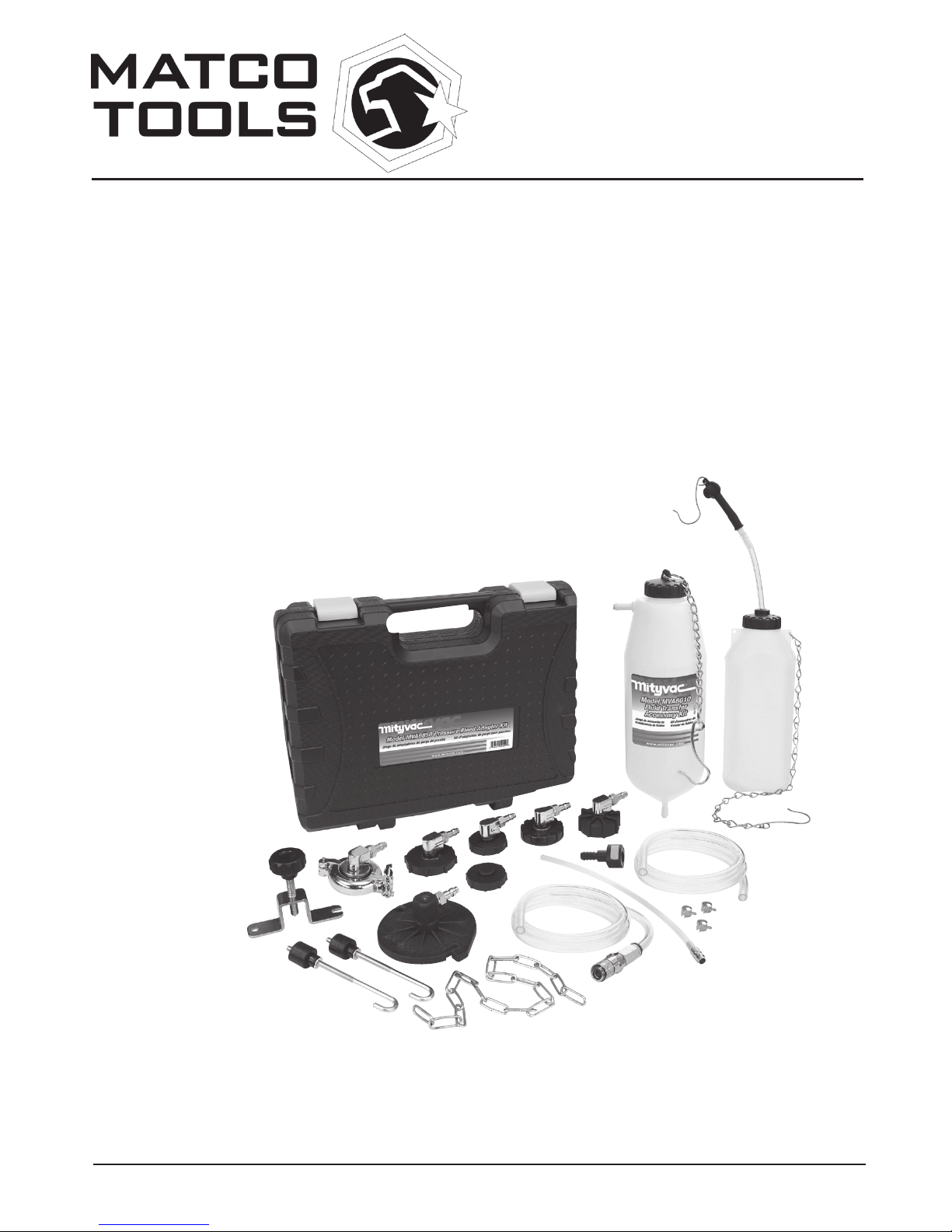
PRESSURE BLEED
ACCESSORY KIT
MODEL MVP6000
Page 2

Page Number - 2 Form 824889
TABLE OF CONTENTS
Service Parts & Accessories . . . . . . . . . . . . . . . . . . . . . . . . . . . 3
Pressure Bleed Adapter Chart . . . . . . . . . . . . . . . . . . . . . . . . . . 4
Principal of Operation . . . . . . . . . . . . . . . . . . . . . . . . . . . . . . . . 5
Instructions for Use . . . . . . . . . . . . . . . . . . . . . . . . . . . . . . . . . . 6
Page 3
Form 824889 Page Number - 3
1
3
2
6
4
7
5
4
8
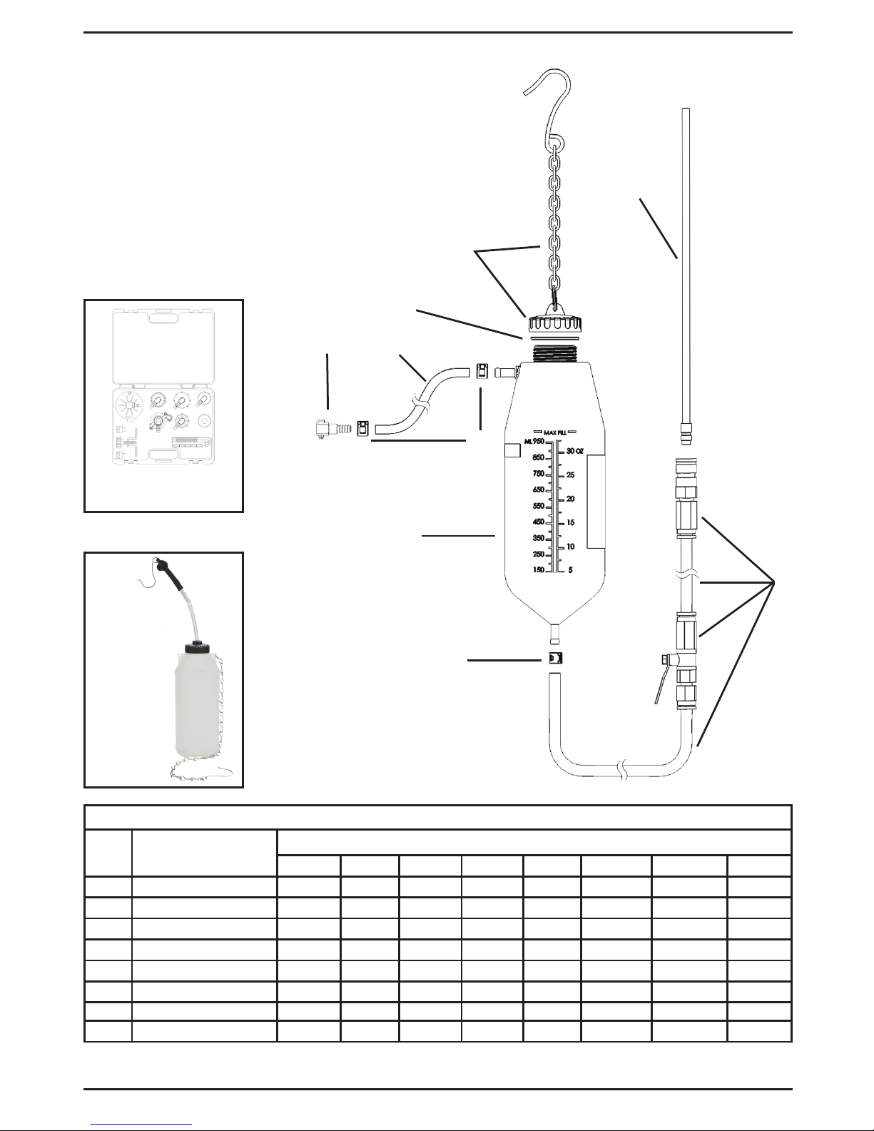
SERVICE/REPLACEMENT PARTS AND KITS
Ref.
No.
Description
PART/KIT NUMBERS
824820 824821 824822 824823 824824 MVA570 MVA7210 824461
1 Cap with Chain 1 pc
2 Cap Seal 1 pc 1 pc
3 8’ Inlet Hose 1 pc
4 Clamp 3 pcs
5 Bottle 1 pc
6 Fluid Hose Assembly 1 pc
7 Dispensing Wand 1 pc
8 Tube Connectors 2 pcs
MVA6839 –
Pressure
Bleed
Reservoir
MVA6850 –
Pressure Bleed Adapter Kit
SERVICE PARTS & ACCESSORIES
Page 4
Page Number - 4 Form 824889
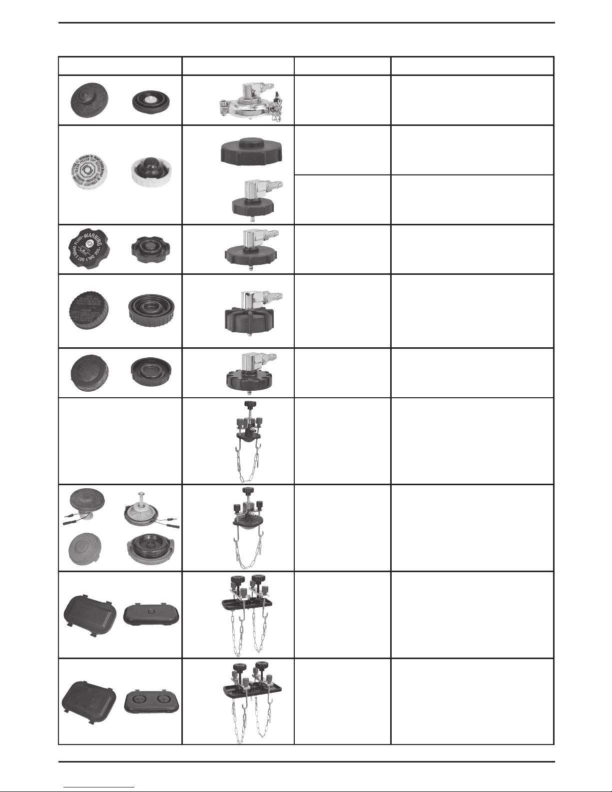
PRESSURE BLEED ADAPTER CHART
Pressure Cap System Adapter # Type Application(s)
MVA800* Locking collar Toyota, Lexus
MVA801*
MVA802*
3-Tab camlock Chrysler, Dodge, Jeep, Plymouth
3-Tab camlock Chrysler, Dodge, Jeep, Plymouth
MVA803* 3-Tab camlock Most late model GM cars (Buick,
Cadillac, Chevrolet, GMC, Hummer,
Oldsmobile, Pontiac) Some Mazda
MVA804* 45 mm thread Most European cars (Alfa Romeo,
Audi, BMW, Jaguar, Land Rover,
Mercedes, Peugeot, Porsche,
Renault, Saab, VW, Volvo), Chrysler
Crossfire, Daewoo, Late model
Ford, Kia, some Mazda, and Mini
MVA808* 3-Tab camlock All Hyundai, Mitsubishi, Nissan,
and Subaru, some Chrysler/Dodge,
some Ford/Lincoln
MVA809 Universal round
cone secured
with chain
Master cylinders with/ small round
necks from 1¼" (32mm) up to 2
1
/8"
(54 mm) internal diameter
MVA810* Universal round
cone secured
with chain
All Acura, Honda, Isuzu, and Suzuki,
some Mitsubishi. Master cylinders
with/ large round necks from 1¾"
(50mm) to 3
5
/16" (80 mm) internal
diameter
MVA811 Face seal secured
with dual chains
Rectangular shaped master cylinders ranging in size up to 3½" x 6"
(90mm x 150mm)
MVA812 Face seal secured
with dual chains
Rectangular shaped master cylinders ranging in size from 3½" x 6"
(90mm x 150 mm) to 4¼" x 7¾"
(108 mm x 200 mm)
*Included in MVA6850 Pressure Bleed Adapter Kit
Page 5

Form 824889 Page Number - 5
This equipment is designed and intended for
use as an accessory to dispense or evacuate
fluids using a Matco hand pressure/vacuum
pump MVP5000 (sold separately). The hand
pump is utilized to build pressure or vacuum in
the fluid transfer bottle. Pressure can be used to
dispense fluid out of the bottle for the purpose
of bleeding hydraulic brake or clutch systems, or
for filling or topping-off various automotive reservoirs. Vacuum can be used to bleed hydraulic
brake or clutch systems, or to evacuate fluids
from various automotive reservoirs.
Fluid is added or emptied from the fluid transfer
bottle through the top by removing the threaded
cap. Pressure or vacuum is applied to the bottle
via a hand pump connected to the inlet hose extending from a nipple near the top of the bottle.
Fluid is dispensed or evacuated through the
fluid hose connected to a nipple extending from
the bottom of the fluid transfer bottle. A fluid
wand is included for connection to the output of
the fluid hose via a quick-change coupler. It can
be used to direct the flow of fluid into a reservoir
or to reach into a reservoir to evacuate fluid out.
The quick-change coupler has an automatic
shut-off valve that will stop fluid flow when the
wand or other accessory is not connected. A
ball valve is installed in the fluid hose to shut-off
or control the flow of fluid to or from the fluid
transfer bottle.
Additional accessories including ATF adapters for topping-off sealed transmissions, are
available for separate purchase, and will greatly
expand the applications of this equipment.
PRECAUTIONS
This equipment is designed for servicing a
variety of vehicles in a safe, convenient manner.
However, differences in vehicle models may
make it impossible to use this equipment as
intended. Do not attempt to force the use of this
equipment on an application for which it is not
designed to perform.
The procedures documented in this manual are
to serve as guidelines for the use of this equipment. In addition to these guidelines, always
follow the manufacturer’s recommended procedures when servicing each unique vehicle.
The use of this equipment is simple and
straightforward if you follow the instructions.
However, always keep in mind that you are
working with a system that may be under
pressure, with fluid that is just waiting to be
expelled. When operating this equipment, use
common sense, and always stop to think before
disconnecting a hose or other component.
This equipment should never be operated above
a safe level of pressure, depending on the
application. When pressurizing the fluid transfer
bottle, always use a hand pump with a pressure gauge installed. When operating the pump,
observe the gauge to ensure the pressure in the
bottle remains at or below the recommended
pressure for the application. Never pressurize the
fluid transfer bottle above 20 psi/1.4 bar/140 kPa.
• This equipment is intended only for profes-
sional use by personnel trained in performing the service functions for which it is has
been designed.
• Read carefully and understand all instruc-
tions prior to using this equipment.
• Always wear eye protection and proper
clothing when operating this equipment
• Some fluids, including brake fluid, are cor-
rosive, and proper care should be taken
to protect painted surfaces and skin from
exposure.
• Do not use this equipment with flammable
liquids, or with fluids at temperatures above
175° Fahrenheit (80° Celsius).
• Consult and follow the vehicle manufac-
turer’s recommended procedure when
using this equipment to perform automotive
service.
ASSEMBLY
1. Using one of the finger clamps (4), secure
the 8' (2.5 m) long clear inlet hose (3) to the
barb located on the side of the fluid transfer
bottle (5).
2. Install the hose adapter (8) into the other
end of the tube (3) and secure it with a hose
clamp (4).
3. Use a finger clamp (4) to secure the 5' (1.5 m)
long hose, valve and quick-change coupler
(6) assembly to the barb extending from the
bottom of the fluid transfer bottle (5).
4. Ensure the cap seal (2) is installed in the
cap, and thread the cap w/ chain assembly
(1) onto the top of the fluid transfer bottle.
PRINCIPAL OF OPERATION
Page 6
Page Number - 6 Form 824889
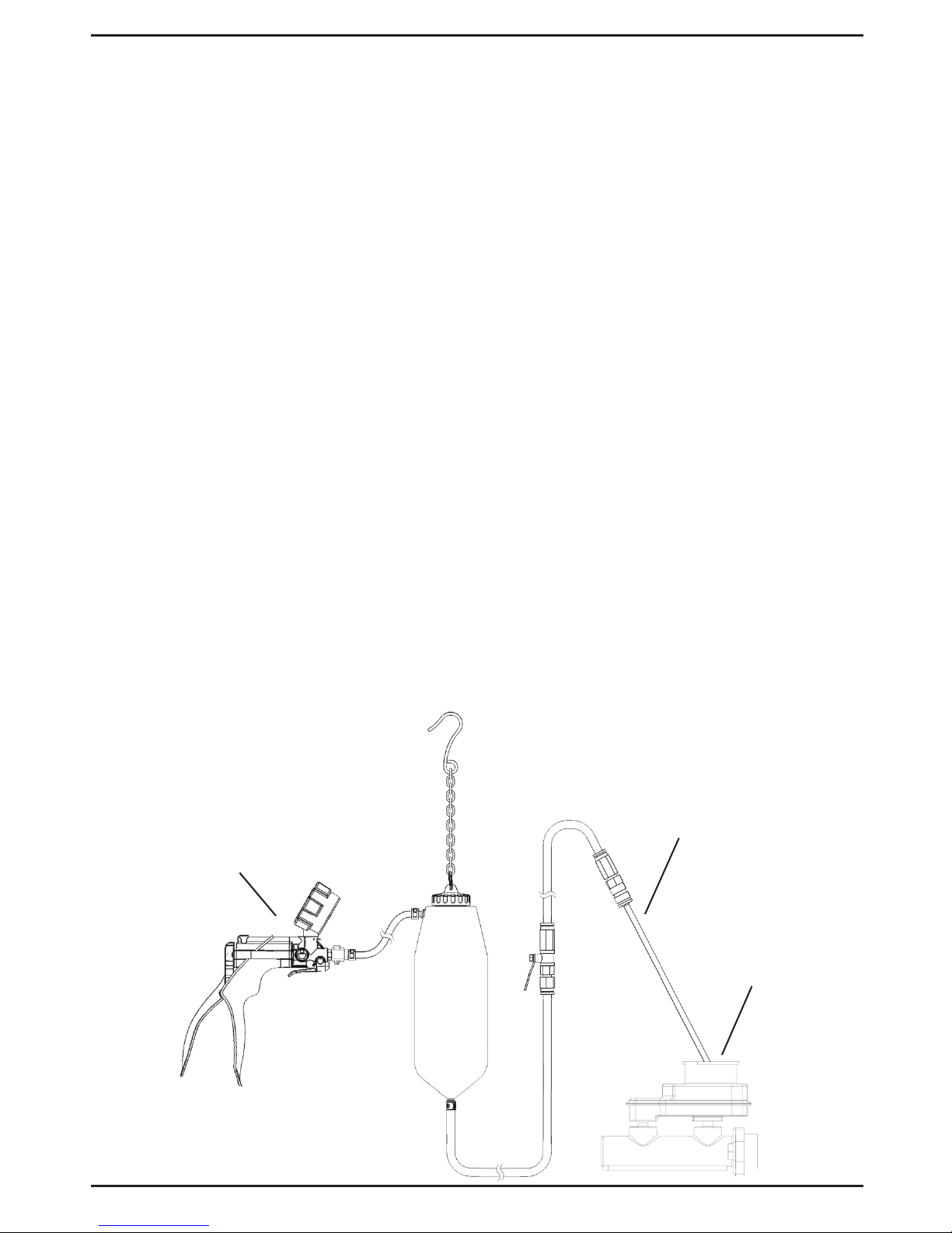
Hand pump
(sold separately)
Fluid dispensing wand
Brake master cylinder
TYPICAL DISPENSING/
EVACUATION APPLICATION
INSTRUCTIONS FOR USE
Fluid Dispensing
1. Unscrew the cap from the fluid transfer
bottle, and fill to desired level with clean
fluid.
2. Reinstall the cap onto the bottle and hang
the assembly in a safe, secure location
within reach of the application.
3. Close the ball valve located on the fluid hose
assembly extending from the bottom of the
bottle.
4. Connect the fluid dispensing wand or other
accessory to the quick-change coupler on
the end of the fluid hose assembly. Ensure
the coupler sleeve snaps forward to lock the
connection.
5. Connect a Mityvac hand pressure pump w/
pressure gauge to the inlet hose extending
from the side of the fluid transfer bottle.
6. While observing the gauge, operate the
pump to build pressure in the fluid transfer
bottle to the desired level. Do not exceed
1.4 bar (20 psi) pressure.
7. Insert the fluid wand into the reservoir you
wish to fill or top-off, and open the ball valve
to allow the flow of fluid.
NOTE: Continual operation of the pump is
not required to maintain fluid flow. Fluid will
continue to flow as long as there is pressure
in the reservoir and the shutoff valve is open.
8. Once the proper amount of fluid has been
dispensed, close the shutoff valve and
release the pressure in the system by activating the pressure relief lever on the hand
pump.
9. Depending on the type of fluid and future
intended use, you may store the remaining
fluid in the reservoir. Otherwise empty the
bottle assembly, clean it with denatured
alcohol or a common household cleaner,
and store it properly.
Fluid Evacuation
1. Hang the fluid transfer bottle assembly in
a safe, secure location within reach of the
application.
2. Close the ball the valve located on the fluid
hose assembly extending from the bottom
of the fluid transfer bottle.
3. Connect the fluid dispensing wand or other
accessory to the quick-change coupler on
the end of the fluid hose assembly. Ensure
the coupler sleeve snaps forward to lock the
connection.
4. Connect a Mityvac hand vacuum pump to
the inlet hose extending from the side of the
fluid transfer bottle.
5. Operate the pump to build vacuum in the
bottle.
Page 7

Form 824889 Page Number - 7
6. Insert the fluid wand into the reservoir from
which you intend to draw fluid, and open the
ball valve to allow the flow of fluid.
NOTE: Continual operation of the pump is
not required to maintain fluid flow. Fluid will
continue to flow as long as there is vacuum
in the reservoir and the shutoff valve is open.
7. Once the required amount of fluid has
been evacuated or the fluid transfer bottle
is full, close the shutoff valve and release
the vacuum in the system by activating the
pressure relief lever on the hand pump.
8. If no future use of the evacuated fluid is
intended, dispose of it properly, clean the
fluid transfer bottle assembly with denatured
alcohol or a common household cleaner,
and store it properly.
Brake Bleeding
Many brake systems today feature Anti-Lock
functions and electronic controls that use a high
pressure electric pump to keep the system
pressurized. Bleeding or servicing these systems requires special procedures and cautions.
Always observe the following precautions when
servicing Anti-Lock brake system:
• ALWAYS wear safety goggles when servicing high pressure brake systems
• ALWAYS depressurize the ABS system
prior to adding fluid or attempting service or
repair
• Unless instructed to by the manufacturer’s
procedure, NEVER open a bleeder valve or
loosen a hydraulic line while the ABS system
is pressurized
• ONLY use recommended brake fluids.
DO NOT use silicone brake fluid in ABS
equipped vehicles.
• Always refer to an appropriate repair manual
for additional information on Anti-Lock brake
systems.
Depressurizing Anti-lock Brake Systems
Always refer to the vehicle owner’s manual or
appropriate service manual for additional information on the depressurizing procedure. The
following procedure will work on most Anti-Lock
brake systems:
1. Ensure ignition switch is in the OFF position
or disconnect the negative battery cable.
2. Pump the brake pedal 25 to 40 times, until a
noticeable change is felt. Continue to pump
the pedal a few additional times. This should
eliminate most system pressure.
3. Open fluid reservoir or brake lines carefully.
Top off reservoir fluid and reconnect battery
cable when finished.
Bleeding Anti-lock Brake Systems
• Always refer to the vehicle owner’s manual
or appropriate service manual for manufacturer’s brake bleeding procedure.
• The front brakes on most Anti-Lock brake
systems may be bled in the conventional
manner.
• Most hydraulic pump/pressure accumulator
units are fitted with a bleeder valve which
must be bled when the system has lost fluid
or is being replaced.
• Some vehicles require the system be
pres¬surized when the rear brakes are bled.
• Some automotive manufacturers use bleeding procedures that require specialized
equipment.
Pressure Bleeding
The Pressure Bleed Accessory Kit is appropriate
for use as a pressure bleeder for hydraulic brake
and clutch systems.
Pressure bleeding is quick and easy because:
• it does not require an assistant
• it maintains pressure in the system while
bleeding multiple locations
• it keeps the master cylinder full during
bleeding
The kit can also be used to identify the presence of leaks in an automotive hydraulic brake
or clutch system. Leaks are indicated by a
drop in pressure over a few seconds or minutes. The locations of leaks can be pinpointed
by visible seepage of fluid from the system
while under pressure.
WARNING: Hydraulic/brake fluid is hazardous
and corrosive. Take precautions to protect
painted surfaces and skin from exposure,
and read and follow the fluid manufacturer’s
warnings and instructions. Always wear safety
goggles when working with brake fluid.
CAUTION: Use your Mityvac Pressure Bleeder
only as directed. Read these instructions completely before attempting to service brakes. The
Mityvac Pressure Bleeder is intended for use
only by individuals experienced with bleeding
and servicing brake systems. If you are unsure
about how to properly service your vehicles
brake system, consult a trained professional.
Always follow the vehicle manufacturer’s directions when bleeding the brake system.
Page 8
Page Number - 8 Form 824889
1. Ensure the vehicle is properly positioned
for safe, convenient access to the master
cylinder and the brake bleed screw located
on each wheel brake cylinder. Set the parking brake, turn off the engine, and open and
secure the hood.
2. Locate the brake or clutch master cylinder
and remove the cap.
3. Extract as much used hydraulic fluid from
the master cylinder reservoir as possible,
and refill it with new fluid.
4. Select the appropriate master cylinder pressure bleed adapter and install it securely
onto the master cylinder reservoir.
5. Hang the fluid transfer bottle assembly in
a safe, secure location within reach of the
master cylinder reservoir.
6. Perform the following procedure before adding any fluid to the fluid transfer bottle:
a. Connect the fluid hose to the male quick-
connect coupler on the master cylinder
pressure bleed adapter. Ensure the coupler
sleeve snaps forward to lock the connection.
b. Consult the vehicle manufacturer’s guide-
lines for the proper bleeding pressure.
c. Connect a Mityvac hand pressure pump
w/ pressure gauge to the inlet hose extending from the side of the fluid transfer bottle.
d. Ensure the shutoff valve on the fluid hose
assembly is open, and operate the manual
pump to pressurize the system to the recommended pressure.
e. Watch the pressure gauge to ensure there
are no leaks. If the pressure drops, relieve
the remaining pressure in the system by activating the pressure relief lever on the hand
pump. Remove and retighten the cap from
the fluid transfer bottle and the adapter on
the master cylinder reservoir, and recheck
the system for leaks.
WARNING: Serious injury and/or equipment
damage can occur if the lid is removed from
the fluid transfer bottle or the adapter from
the master cylinder, without first relieving
the system pressure.
7. Once all connections are proven secure and
the master cylinder adapter does not leak,
remove the cap from the fluid transfer bottle
and add up to 1 liter (1 quart ) of the vehicle
manufacturer’s recommended new hydraulic
fluid from a sealed container.
8. Reinstall the cap onto the fluid transfer
bottle and tighten it securely.
9. Consult the vehicle manufacturer’s guidelines for the proper wheel bleeding sequence and pressure bleeding procedure.
10. Observing the pressure gauge, operate the
hand pressure pump to achieve the recom-
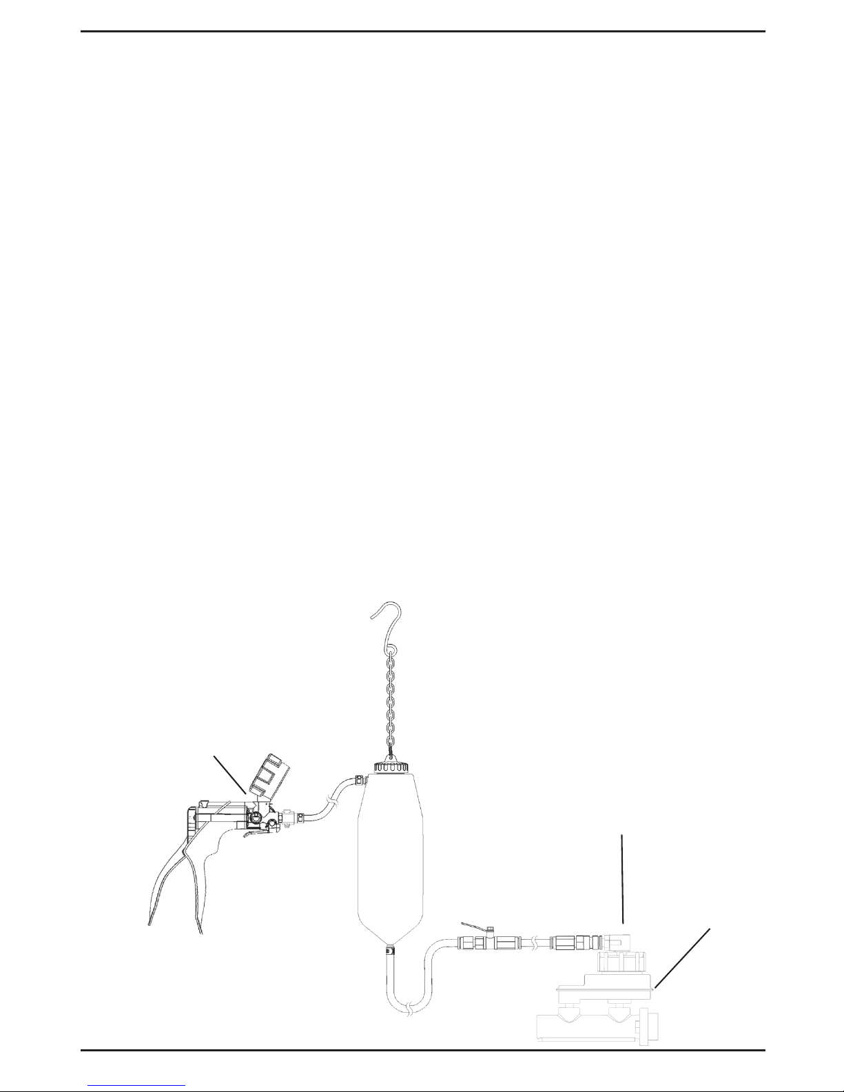
Hand pump
(sold separately)
Brake
master
cylinder
TYPICAL PRESSURE BLEED APPLICATION
Pressure
Bleed
Adapter
Page 9

Form 824889 Page Number - 9
mended pressure. Do not exceed 1.4 bar
(20 psi) pressure.
11. Connect a bleed reservoir to the bleed
screw of the first cylinder to be bled.
12. Open the bleed screw. Allow fluid to flow
out until only clear new fluid with no visible
air bubbles is streaming from the screw,
and then re-tighten the bleed screw to the
manufacturer’s recommended torque.
13. Perform the same procedure on all remaining bleed screws. Operate the pressure
pump as required to maintain adequate
pressure.
NOTE: Do not allow the fluid transfer bottle
and master cylinder reservoir to run dry. Use
the pressure relief lever on the hand pump
to relieve the system pressure and add new
fluid if necessary.
14. Once bleeding is complete, relieve the pressure in the system by activating the pressure
relief lever on the hand pump.
15. Close the fluid dispensing hose shutoff
valve, disconnect the fluid hose by pulling
back on the coupler sleeve, and carefully remove the adapter from the master cylinder,
being careful not spill any brake fluid.
16. Extract excess fluid or top-off the master
cylinder as required, and replace the cap.
17. Dispose of any hydraulic fluid remaining in
the fluid transfer bottle. Do not store hydraulic fluid in the bottle. Clean the fluid transfer
bottle assembly with denatured alcohol and
store it properly.
18. Test the brake or clutch system for leaks
before driving the car.
Vacuum Brake Bleeding
The Fluid Transfer Accessory Kit provides a
simple, clean, and quick method for vacuum
bleeding the fluid lines in an automotive brake
system. It operates by creating a vacuum in the
bottle, which draws fluid from the lines via the
wheel cylinder bleed screws.
1. Ensure the vehicle is properly positioned
for safe, convenient access to the master
cylinder, and the brake bleed screw located
on each wheel brake cylinder. Set the parking brake, turn off the engine, and open and
secure the hood.
NOTE: Make certain the master cylinder
reservoir is filled and a supply of new, clean
brake fluid of the proper type is on hand to
top off the reservoir as the fluid level drops
during bleeding. Make sure all the bleeding
fittings are clean prior to beginning of the
bleeding procedure.
NOTE: Consult the vehicle manufacturer’s
guidelines for the proper wheel bleeding
sequence and vacuum bleeding procedure.
2. Disconnect the quick-change coupler from
the end of the fluid hose extending from the
bottom of the fluid transfer bottle by pulling
back on the blue sleeve of the coupler to
release it from the hose.
3. Insert the appropriate brake bleed adapter
into the end of the fluid hose in place of the
coupler.
NOTE: Brake bleed adapters are not in-
cluded with the fluid transfer accessory kit,
but come standard with most Mityvac hand
pump kits, or can be purchased separately.
In many cases, the end of the fluid hose can
be slipped directly onto the bleed screw
nipple, eliminating the need for a brake
bleed adapter.
4. Following the vehicle manufacturer’s recommended bleed procedure, hang the fluid
transfer bottle assembly in a safe, secure
location within reach of the first wheel cylinder to be bled, and open the shut-off valve
located on the fluid hose assembly.
5. Connect a Mityvac hand vacuum pump to
the inlet hose extending from the side of the
fluid transfer bottle.
6. Slide a wrench securely onto the hex of the
wheel cylinder bleed screw, and then slip
the bleed screw adapter or fluid hose over
the bleed screw nipple.
7. Operate the hand pump 10 to 15 times to
build vacuum in the fluid transfer bottle,
and turn the wrench to open the fitting only
enough to allow fluid to flow; usually 1/4 to
1/2 turn.
NOTE: A tiny stream of bubbles may be
noticed in the hose after all of the air is bled
from the lines. This is caused by air seeping
around the threads of the loosened bleeder
fitting and being drawn back through the
fitting by the suction of the pump. Once the
air is removed from within the system, these
tiny bubbles will in no way jeopardize the
bleeding operation, since they are present
only at the fitting and do not enter the system. Applying grease or Teflon tape around
the threads of the fitting will eliminate most
of the bubbles.
Page 10

Page Number - 10 Form 824889
8. Keep the bleed screw open and continue to
operate the vacuum pump as required until
new fluid is visibly flowing through the bleed
tube.
9. Without over-tightening, close the bleed
screw firmly prior to removing the bleed
screw adapter or hose from the bleed
screw, or relieving the vacuum from the
system.
NOTE: It is important to ensure the bleed
screw adapter remains connected to the
bleed screw, and the bleeder is still pulling
a vacuum while the bleed screw is closed.
This prevents air from being sucked back
into the wheel cylinder from around the
bleed screw threads, before the bleed screw
is tightened and sealed.
NOTE: If an automatic master cylinder refill
accessory is not being used, be sure to
periodically check the level and top off the
brake fluid in the master cylinder so it does
not run dry.
Topping-off Sealed Automatic
Transmissions
The Fluid Transfer Accessory Kit is appropriate
for use to refill or top-off sealed automatic transmissions. Additional accessories and adapters
may be required and available from Matco for
performing this function.
1. Unscrew the cap from the fluid transfer bottle, and fill to desired level with the vehicle
manufacturer’s recommended transmission
fluid.
CAUTION: Lifetime “sealed” transmissions
require the use of special manufacturer
recommended fluids. Use of any other fluids
may cause severe damage to the transmission and void the manufacturer’s warranty
2. Reinstall the cap onto the bottle and hang
the assembly in a safe, secure location
within reach of the transmission fill port.
3. Close the ball the valve located on the fluid
hose assembly extending from the bottom
of the bottle.
4. Connect a Mityvac hand pressure pump w/
pressure gauge to the inlet hose extending
from the side of the fluid transfer bottle.
5. Depending on the application, select the appropriate ATF refill adapter and perform one
of the following series of steps:
Connect the ATF refill adapter to the trans-
mission fill port; then connect the fluid hose
extending from the bottom of the fluid transfer bottle to the other end of the adapter.
-or-
Connect the ATF refill adapter to the fluid
hose extending from the bottom of the fluid
transfer bottle; then insert the adapter into
transmission fill port.
6. Open the shut-off valve, and while observing
the pressure gauge, operate the pump to
build pressure in the reservoir to the desired
level, or until the proper amount of fluid has
been dispensed. Do not exceed 1.4 bar (20
psi) pressure in the system.
NOTE: Check the vehicle’s service manual
to determine the proper method to check
the transmission fluid level. Failure to follow
the manufacturer’s recommended procedure could result in under- or over-filling the
transmission, causing severe transmission
damage.
It is not necessary to relieve the pressure in
the fluid transfer bottle or close the shut-off
valve if the hose must be disconnected from
the adapter to check the transmission fluid
level. An automatic shut-off valve is built
into the quick-change coupler, which will
prevent the discharge of fluid if the coupler
is disconnected from the adapter.
Continual operation of the pump is not
required to maintain fluid flow. Fluid will
continue to flow as long as there is pressure
in the reservoir, the hose is connected to the
adapter, and the shutoff valve is open.
If the transmission is over-filled, you may
reverse the hand pump to pull a vacuum
on the system to remove and capture the
excess fluid.
7. Once the proper amount of fluid has been
dispensed, close the shutoff valve and
release the pressure in the system by activating the pressure relief lever on the hand
pump.
8. Depending on the type of fluid and future
intended use, you may store the remaining fluid from the reservoir. Otherwise,
empty the fluid transfer bottle, clean it with
denatured alcohol or a common household
cleaner, and store it properly.
 Loading...