

Page 1
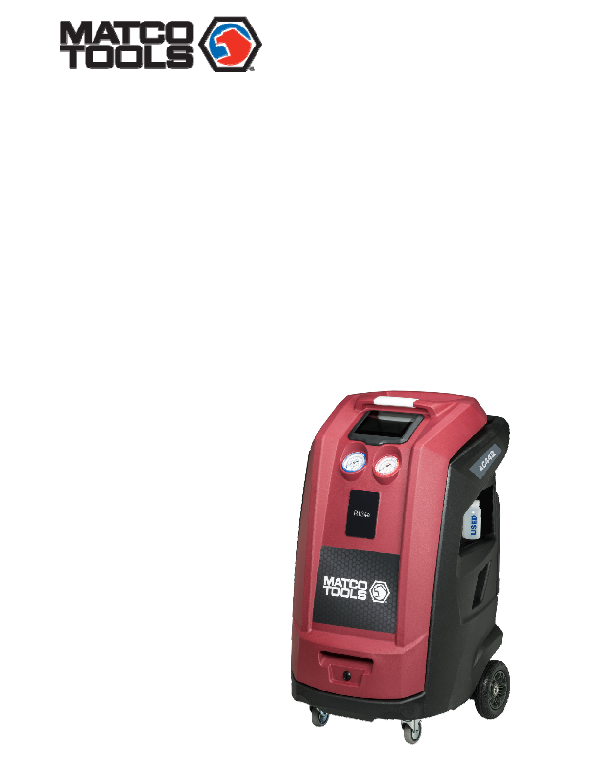
Foreword
AC442
TSL-50 | 1
R134a TOUCHSCREEN AUTOMATIC RRR
Operation Manual
EN
A/C Service Equipment
1901016-85
Page 2

2
en
| AC442 |
1901016-85
Page 3

Contents
1Symbols use
1.1
In the documentation...............................4
1.1.1
Warning notices- Structure and
meaning...................................................................4
1.1.2Symbols in this documentation
1.2
On the product...........................................4
2 Important notes ........................... 4
2.1
User group
2.2
Agreement
2.3
Obligation of contractor
2.4
Safety regulations
2.4.1AC442
2.5
Safety devices............................................8
2.6
Proper disposal..........................................8
2.7
Recycled material disposal.....................8
2.8
Packaging disposal....................................8
2.9
Disposal of combo filter...........................8
2.10
Technical Data............................................8
2.11
Glossary.......................................................8
3 Product description ..................... 9
3.1
Application
3.2
Scope of delivery
Description of unit ..................... 10
4
5
Input Selection .......................... 12
5.1
Selection and function key....................12
5.2
Display screen..........................................13
5.3
Main Menu Options................................13
5.4
Unit Features............................................13
5.4.1
EcoLOCK ® couplers (optional)......13
5.4.2Locking caster brakes
5.4.3Power supply cable and switch
5.5
Functional description
6 Equipment installation............... 15
6.1
Unpacking AC442
................................................... 4
.....4
................................................4
.................................................4
......................5
..................................6
.......................................................6
.................................................9
....................................9
......................13
...13
........................14
.................................15
| AC442 | 3
7
Commissioning .......................... 16
7.1
Connections and positioning
7.2
7.3
7.4
First start-up verification
Setup
Internal Bottle Fill
.........................................................17
.................................17
...................16
8 A/C service preparation .............. 18
8.1
8.2
8.3
8.3.1Quick Modes
Preliminary preparation
Non-condensable gas discharge
Charge Modes
.........................................18
........................................18
8.3.2Zero tolerance mode
.....................18
.......................18
9 A/C system service ..................... 19
9.1
Automatic cycle setup............................19
9.2
Manual cycle setup.................................19
9.3
Recovery process....................................20
9.4
Vacuum process......................................20
9.5
Charge process........................................20
9.6
Vehicle Pressure Check
9.7
Unit of measure
9.8
Clock
9.9
Setting language.....................................21
Adjustment...................................21
....................................21
......................21
10
Maintenance ............................... 22
10.1
Maintenance interval
10.2
Filling internal refrigerant cylinder
10.3
10.4
10.5
10.6
10.7
10.8
10.9
Self test
Pressure zero
Counters
Long life pump test
Vacuum pump oil change
Replace filter dryer
Printer maintenance (optional)
.....................................................23
..........................................23
....................................................23
10.10Periodic checks
..........................22
..............................23
..................24
................................24
......................................25
11
Spare parts ................................. 26
12
Maintenance ............................... 27
12.1
Vacuum pump oil change.....................27
12.2
Filter dryer change..................................29
12.3
Refrigerant load cell calibration check32
12.4
Other checks/maintenance/repairs......33
12.5
Notes..........................................................35
en
............16
.....18
22
.......25
1901016-85
Page 4
4
en
1 Symbols use
| AC442 |
1.1 In the documentation
1.1.1 Warning notices- Structure and
meaning
Warning notices warn of dangers to the user or
people in the vicinity. Warning notices also indicate
the consequences of the hazard as well as preventive
action. Warning notices have the following structure
Warning
symbol
KEYWORD - Nature and source of
hazard!
event of failure
Consequences of hazard in the
to observe action and
information given.
Hazard prevention action information.
The key word indicates the likelihood of occurrence and
severity of the hazard in the event of non-observance:
the
Key wor d
DANGER Immediate impending
WARNING Possible impending
CAUTION
Probability of
occurrence
danger
danger
Possible dangerous
situation
Severity of danger
if instructions not
observed
Death or severe injury
Death or severe injury
Minor injury
1.1.2 Symbols in this documentation
Symbol
Designation Explanation
1.
2.
Attention
Information
Multi-step
operation
One-step
operation
Intermediate
result
Final result
Warns about possible property
damage
Practical hints and other useful
information.
Instruction consisting of several steps.
Instruction consisting of one step.
An instruction produces a visible
intermediate result.
There is a visible final result on
completion of the instruction.
1.2 On the product
Observe all warning notices on products and
ensure they remain legible.
Wear protective goggles.
Wear protective gloves.
2 Important notes
Before start up, connecting and
operating MATCO
absolutely essential that the
Original
:
manual and, in particular, the
studied carefully. By doing so you can eliminate any
uncertainties in handling MATCO products and thus
associated safety risks upfront; something which
in the interests of your own safety and will
ultimately help avoid damage to the device. When
a MATCO product is handed over to another
person, not only the Original instructions but also
the safety instructions and information on its
designated use mu st
person.
2.1 User group
The product may be used by skilled and instructed
personnel only. Personnel scheduled to be trained,
familiarized, and instructed or to take part in a general
training course may only work with the product under
the supervision of an experienced person. All work
conducted on pressurized equipment may be
performed by persons with sufficient knowledge and
experience in the field of refrigeration, cooling
systems and coolants and, also be aware of the risks
involved in the use of pressurized devices
2.2 Agreement
By using the product you agree to the following
regulations:
Copyright
instructions/owner’s
be handed over to the
products it is
safety instructions are
is
Software and data are the property of MATCO or its
suppliers
copyright laws, international
national legal regulations. Copying or sell
and software or an y part th ereof is imp ermiss ible an d
punishable; in the event of any infringements
MATCO reserves
prosecution and to claim for damages.
and protected against copying by
agreements and other
ing of data
the right to proceed with criminal
1901016-85
Page 5

Liability
All data in this program is based—where possible—on
manufacturer and importer details. MATCO does not
accept liability for the
software and data; MATCO shall not be liable for damage
caused by faulty software and data. Whatever the event,
MATCO’s liability is restricted to the amount the customer
actually pays for the product. The disclaimer of liability
does not apply to intentional damages or damages caused
by gross negligence of MATCO.
correctness and completeness of
Warranty
Any use of non-approved hardware and software will
result in a modification to our product and thus to
exclusion of any liability and warranty, even if the
hardware or software has in the meantime been removed
or deleted.
No changes may be made to our products. Our products
may only be used in combination with original
accessories and original service parts. Failing to do so,
will render null and void all warranty claims.
This product may only be operated using MATCO
approved
using an operating
then our warranty obligation
conditions will be rendered null and void.
will not be held liable for damage and consequential
damage incurred through the use of a non-approved
operating system.
operating systems. If the product is operated
system other than the approved one,
pursuant to our supply
Furthermore, we
| AC442 | 5
en
2.3 Obligation of contractor
The contractor is obliged to ensure that all
measures geared
accidents, industrial diseases, laborrisks are taken and measures towards making the
workplace fit for people
towards the prevention of
related health
to work in are carried out.
Basic rules
The contractor is bound to ensure that all electrical
equipment
modified and maintained by
only or under the guidance and supervision
skilled electrician in accordance with electrical
engineering principles.
and operating material is set up,
skilled electricians
of a
Furthermore, the contractor must ensure that all
electrical equip
operated in keeping with electrical engineering
principles.
ment and operating material is
If a piece of electrical equipment or operating
material is found to be defective, i.e. It does not
or no longer complies with electrical engineering
principles, the contractor must ensure that the
fault is rectified immediately and, in the event
that imminent danger exists, also ensure that the
electrical equipment or the electrical operating
material is not used.
Tests (taking Germany as an example)
The contractor must ensure that all electrical systems and
equipment are tested by a qualified electrician or under
the guidance of a qualified electrician to ensure they are in
proper
working order:
— Before starting for the first time.
— After modifications or repairs before starting
— At given intervals. Set intervals such as to ensure
that faults that can be expected to occur are
determined in good time.
The test is to take the electrical engineering principles
relating hereto into account.
Upon request of the free trade association, a test manual
is to be maintained into which specific entries are made.
1901016-85
Page 6
6
en
| AC442 |
2.4 Safety regulations
2.4.1
Always carefully study and follow all the safety regulations before using
the MATCO product.
AC442
Avoid all skin contact with the refrigerant. The low
boiling point of the refrigerant (approx. -30° C) can
lead to frostbite. Should refrigerant come into
contact with the skin, remove any moistened
clothing immediately and rinse the area of skin
affected with generous amounts of water.
Avoid all skin contact with the UV dye. Should UV dye
come into contact with the skin, remove any moistened
clothing immediately and rinse the area affected with
generous amounts of water.
R134a is colorless, with weak characteristic smell and
heavier than air. It may flow into repair pits. Should
refrigerant escape, Provide for sufficient ventilation
(particularly in repair pits) and leave the workshop.
Never inhale refrigerant, dye and oil vapors. The
vapors can irritate the eyes, nose and respiratory
system. If liquid refrigerant or UV dye comes into
contact with the eyes, rinse them thoroughly with
water for 15 minutes. Then obtain medical attention
even if no pain is felt
Never swallow UV dye. Should it be swallowed
inadvertently, never attempt to induce vomiting. Drink
generous amounts of water and obtain medical attention.
Before connecting the AC442 to a vehicle air conditioning
system or an external refrigerant bottle, make sure the
quick-release couplings are not leaking. Only ever use
external refrigerant bottles provided with safety valves
and certified in line with applicable standards.
Before switching off the AC442, make sure all charging
and drainage operations have been completed. This
prevents damage to the unit and reduces the risk of
refrigerant escaping into the environment.
Never use compressed air with R134a. Certain
mixtures of air and R134a are highly flammable.
Such mixtures are a potential hazard and may
lead to fire or explosions and thus cause damage
or injury.
Refrigerant extracted from a vehicle air conditioning
system may be contaminated wi th moisture, lubricant, dirt
and traces
of other gases.
If the refrigerant has been contaminated by being
mixed with other gases, remove the
contaminated refrigerant and add fresh R134a
before using the AC442 for A/C service.
R134a is not to be used in areas in which there is
a danger of explosion. Fire, open flames and
smoking are prohibited.
The AC442 unit should not be exposed to excess
moisture or be operated in wet areas
R134a is not to be mixed with other refrigerants. The
mixing of refrigerants could damage the vehicle air
conditioning system.
De-energizing is only to be performed by a qualified
electrician, a qualified electrician for specific tasks
(hybrid) or a power systems engineer.
If high-voltage components or high-voltage wires
are
handled incorrectly, there is a risk of fata l
injury from high voltage and the possible
transmission of current
through the body.
Work on vehicles with high-voltage components is only
ever to be performed in a safe de-energized condition by
persons with the minimum qualification “Trained to
perform electrical work”.
Even after deactivating a high-voltage vehicle electrical
tem, the high-voltage battery may still be live.
sys
Operating condition cannot be established from any
running
stationary.
In gear positions "P" and "N" the engine or electric
motor
charge of the
Never open or damage high-voltage batteries.
noise, as the electric machine is silent when
may start spontaneously depending on the
high-voltage battery.
On vehicles that have been in an accident, never touch
high-
voltage components or exposed high-voltage
wires before
electrical system.
deactivating the high-voltage vehicle
The AC442 must be con stantly monitored when i n
tion. Never leave the AC442 unattended when in
opera
operation.
prepared and implemented such that the vehicle air
conditioning system circuit does not have to be opened
(for exam ple by removing
Vehicle A/C service using the AC442 must be
the radiator or engine).
Position the AC442 on all four wheels on a flat,
vibration- proof surface so that proper operation of the
scales is guaranteed
Vehicle A/C service using the AC442 must be prepared
and implemented such that the vehicle air conditioning
system circuit does not have to be opened (for example
by removing the radiator or engine).
The AC442 can be secured in position by locking
the caster brake.
1901016-85
Page 7

The AC442 must al ways be transported in its operating
position. Never lay the AC442 on its side, as oil could
then escape from the vacuum pump or the built in
compres
safety systems for protecting the
damage resulting from natural catastrophes.
sor could be damaged.
There are no additional
AC442 again st
We recommend calibrating the scales at least once per
Contact customer service for calibration of the scales.
year.
The AC442 must be subjected to regular maintenance by
service personnel or authorized agents to ensure the safety
of the unit.
Disconnect power before performing any maintenance
service to unit.
or
Never perform any maintenance work which is not
expressly
customer service if
other than in the course of
The AC442 must be connected to a properly grounded
electrical connection.
recommended in this manual. Contact
components have to be replaced
maintenance work.
| AC442 | 7
en
If there i s dama ge to th e AC442, terminate u sage
imme
diately and contact customer service.
The service hoses and service quick-release couplings must
be regularly checked for wear and replaced if damaged.
The AC442 must be operated in an environment
corresponding to the directive BGR 157 with respect to
the exchange of air.
Observe local laws or directives as to ensure the safety of the
pressurized device.
Follow the pertinent legal regulations or directives to
ensure
safe handling of pressurized devices.
For safety reasons it is advisable to use a residual current
operated circuit breaker (rccb) with the following
specifications:
Parameters
Rated voltage
Rated frequency
Rated current
Rated tripping current 30mA
Tripping switch
50/60Hz
10A
Never remove any components from inside the AC442
except for maintenance or repair purposes.
110 VAC ± 10%
C
Avoid using an extension cord with the unit. If
necessary, use a good condition (three wire grounded,
#14AWG or larger) extension cord of the shortest
possible length. In addition, the current drawn by all
devices connected to the wall socket must not exceed
15A total.
1901016-85
Page 8
8
en
| AC442 |
2.5 Safety devices
Description Function
Pressure
switch
Safety valve The safety valve opens if the design pressure is
Circuit
Breaker
Vents The AC442 is provided with vents in the housing to
Switches the compressor off in the normal operating
pressure is exceeded
exceeded
Interrupts the power supply if overcurrent is applied to
the AC442
ensure the exchange of air even when switched off.
2.6 Proper disposal
At the end of its service life, this equipment must
be disposed of as follows:
— Contact the service center to have the refrigerant
in the unit recovered and recycled.
— Consign the unit to an authorized collection
center according to local legislation.
2.7 Recycled material disposal
Return the refrigerant recovered from
—
the unit to the refrigerant supplier for
proper disposal or recycling.
— Lubricants extracted from the vehicle's
A/C system must be returned to an
official oil collection center
2.8 Packaging disposal
Electronic and electrical A/C service
equipment must never be disposed of with
domestic waste, but recycled
appropriately.
— The packaging must be disposed of in
conformity with local legislation.
— This contributes to protecting the
environment
2.9 Disposal of combo filter
Dispose of the filter via official
—
collection points or in accordance with
the local regulations. This contributes
to protecting the environment
2.10 Technical Data
Description Specification
R134a tank capacity 12L
Service pressure 400PSI
Maximum content 22lbs.
Method to weigh gas content Load cell
Recovered oil container 250ml
Vacuum pump 2CFM dual stage
Vacuum pump oil quantity 250ml
Compressor capacity 0.87cu in/14cc
Dryer filter 90kg recovered R134a
Non-condensable gas purge Automatic via solenoid valve
HP and LP taps Automatic
Display 7 inch capacitive touch screen
Software updating
Printer (optional) Thermal, 24 columns
All functions Automatic and manual
Recycling mode Single pass
Memory for customized
cycles
Flushing With integrated solenoid valves
System pressure diagnostics Manual and automatic
Dryer filter replacement alarm Active
Vacuum pump oil
replacement alarm
Full/empty tank check alarm Active
Full oil container check alarm Visual
Empty oil container alarm Visual
Dimension H x W x D 119 x 74 x 74 cm
Dry weight 98kg
Power supply frequency 60Hz
Voltage 120VAC, 1 phase
Total max load 7.5A
Overcurrent protection 12A (circuit breaker)
Operating temperature 50 - 122°F
Humidity 10 90%RH (non-condensing)
Storage temperature and
humidity
Max operating altitude 6562 ft.
Pollution degree 2
Water degree 0
Certifications
USB type A or USB type B direct
connect to PC
100 records
Active
-13 to 50°F
10 - 90%RH (non-condensing)
SAE J2788
UL 1963
CAN/CSA STD C22.2NO. 120 –
M91
2.11 Glossary
Recovery phase: The refrigerant is extracted from the
vehicle air conditioning system, cleaned and routed into the
internal bottle of the AC442. The refrigerant oil collected in
the process is drained into the used oil bottle at the AC442.
Vacuum phase: A vacuum is generated in the vehicle air
conditioning system. Measurement of the drop in pressure
begins as soon as the vacuum has been generated.
Charging phase: A certain quantity of refrigerant is added
to the vehicle air conditioning system.
1901016-85
Page 9

Description of unit |
AC442 | 9 en
3 Product description
3.1 Application
AC442 is suitable for vehicles with a conventional engine
well as for hyb rid and electric vehicles. AC442 featu res all
as
the
functions required for vehicle A/C service.
The following functions can be implemented:
Refrigerant recovery and recharging.
Vacuum generation.
Flushing.
The AC442 can only be operated with R134a. The
m
AC442 is not to be used for service work on vehicles
with air conditioning systems employing refrigerants
other
than R134a, as this will cause damage. Prior to A/C
service
air condition
3.2 Scope of delivery
Description
Service hose (high pressure)
Service hose (low pressure)
Quick-release coupling (high pressure)
Quick-release coupling (low pressure)
Used oil bottle
Original instructions
Adapter (external bottle) - US Acme 1/2
Calibration check weight
check the type of refrigerant used in the vehicle
ing system.
1901016-85
Page 10

10
en
| AC442 | Description of unit
4 Description of unit
Fig. 1: Front Right View
1.
Rear Handle
2.
Tool Tray
3.
Status indicator light
4.
LCD display
5.
Low Pressure Gauge
6.
High Pressure Gauge
7.
Front Cover
8.
Locking Caster
9.
Rear Wheel
10.
Printer (optional)
11.
Used oil bottle
Fig. 2: Rear View
1.
Service Hoses
2.
Fan
3.
Vent
4.
Hose Storage
Figure A: Rear Connection View
1.
High Side Parking Coupler
2.
Low Side Parking Coupler
3.
Refrigerant Identifier (Optional)
4.
Power Switch with circuit breaker
5.
Power Cord socket
Fig. 3 Front left view
1.
Vacuum pump oil level sight glass
1901016-85
Page 11
Description of unit |
AC442 | 11 en
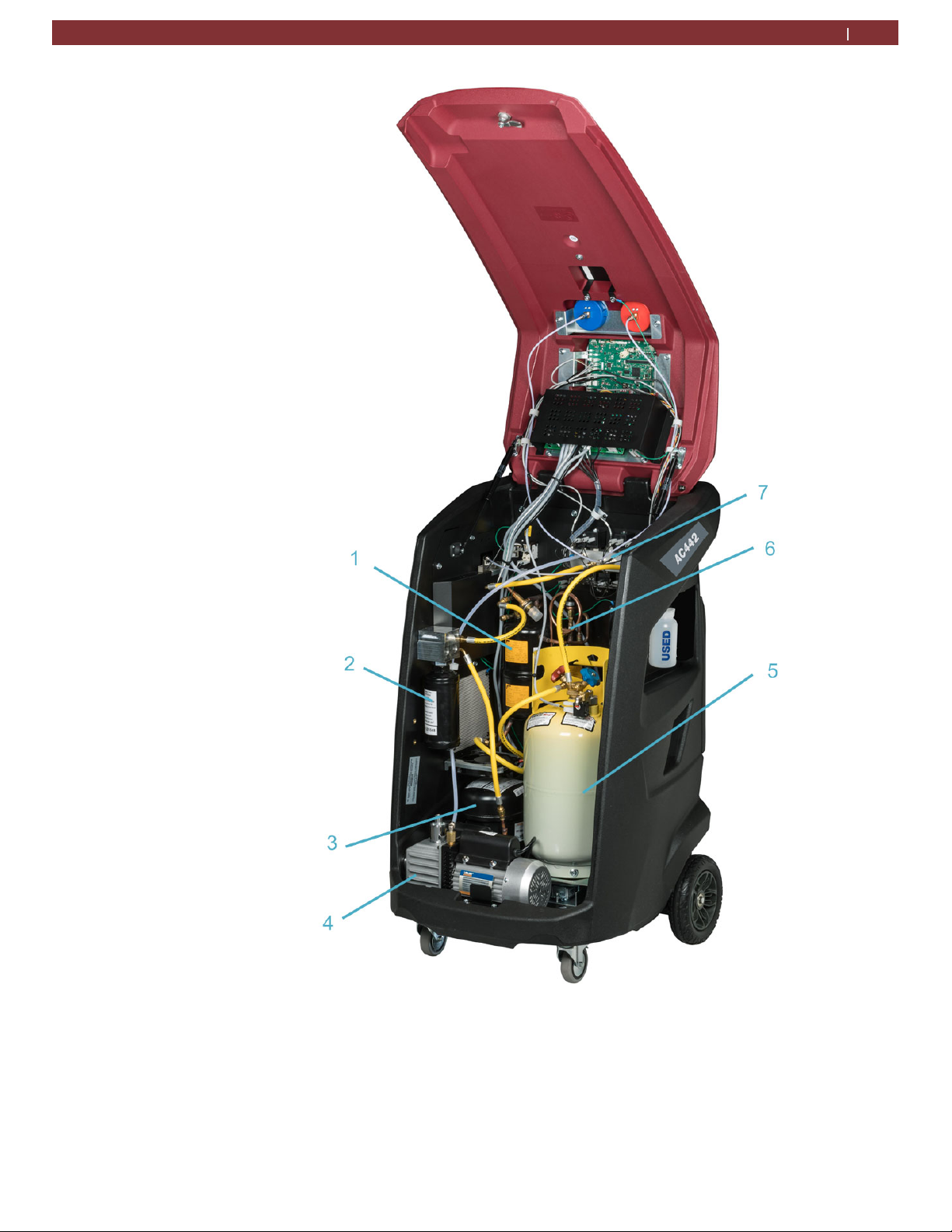
Fig. 4: Internal components
1.
Accumulator/Oil separator
2.
Combo filter
3.
Compressor
4.
Vacuum pump
5.
Refrigerant tank
6.
HS compressor oil separator
7.
Manifold
1901016-85
Page 12
Description of unit | AC442 | 12 en
To select a function in the menu, press the text name of the
function and the selection occurs when finger is released. The
selected entry is highlighted with a different color (from blue to
gray) and the menu screen pages changes.
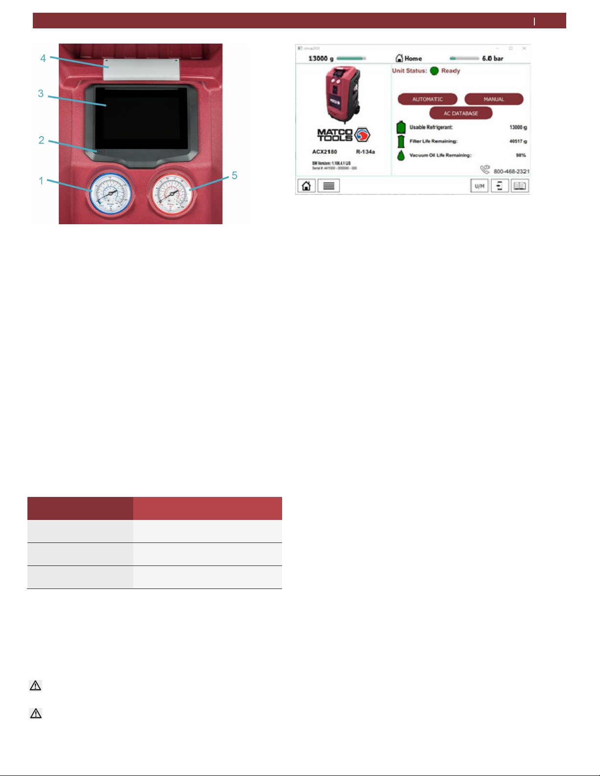
Fig. 5: Display and control panel
1.
Low pressure gauge
2.
LCD Touch Screen
3.
Status and warning Indicator light
4.
High pressure gauge
5.
USB port
Fig. 6: AC442 Home Screen
If there are menus that cannot fit on one screen, there will be
arrows located on a side of the screen. By placing finger on
screen and swiping left/right, the screen options will also move.
The menu selection and necessary entries are made by way of the
LCD touch screen (Fig. 5, Pos. 2) integrated in the panel.
The pressure gauges (Fig. 5, Pos.1,4) of the display and operating
unit are used to monitor the pressure during the individual
vehicle A/C service phases. The status of the various service
phases during maintenance is displayed on the LCD screen (Fig.
5, Pos. 2).
The status and warning indicator light (Fig. 5 Pos. 3) indicates the
service status. See chart below for further definition.
Status and warning light color Maintenance status
Red Light Error/warning
Flashing green Operation in progress
Green light Operation complete/Attention Operator
5
Input Selection
5.1 Selection and function key
All settings, controls and service functions are available on the
LCD touch display. Data entry and moving of the cursor is
performed with user's finger or another object such as a pen or
stylus. The LCD displays the service equipment's status, the
progress of A/C system service and any alarms/error messages.
Do not use a sharp, pointed object on the touch screen.
Damage may occur!
Although the LCD touch screen is glass, do not use harsh
chemicals to clean the surface. Standard glass cleaner is
recommended.
1901016-85
Page 13
en
13 | AC442 | Description of unit
5.2 Display screen
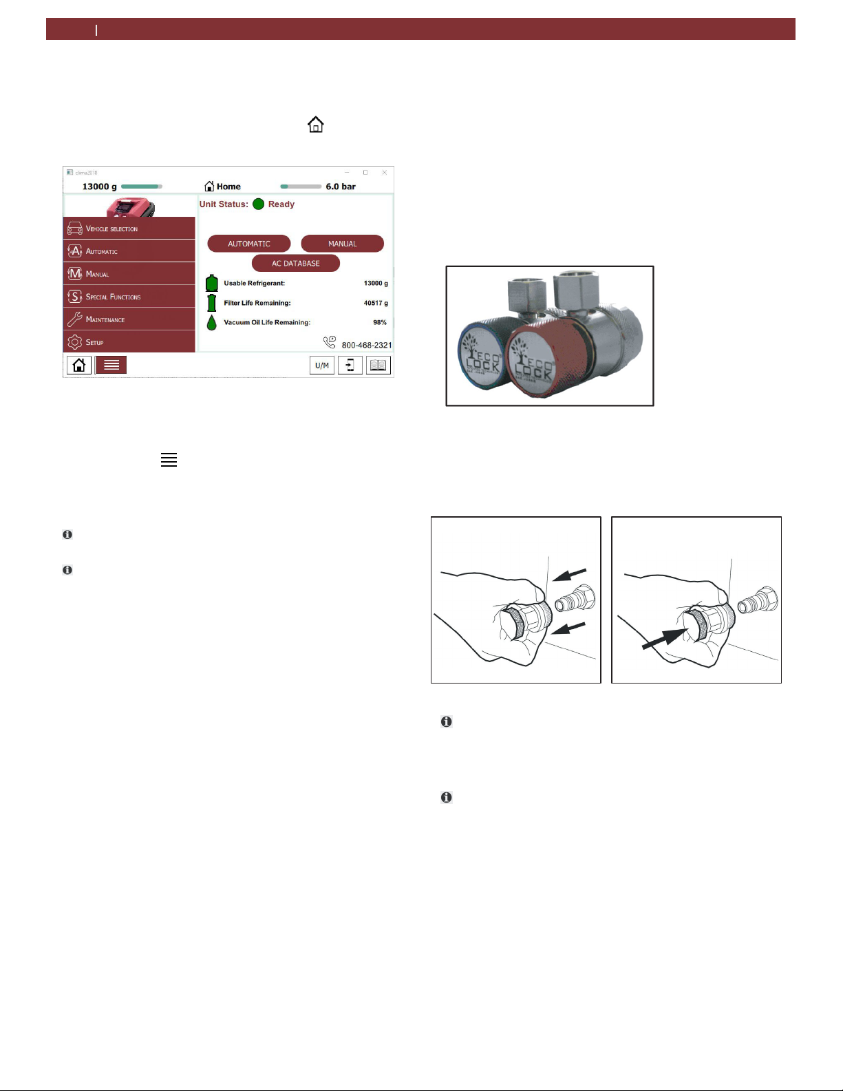
When unit loads, the home screen will be displayed (Fig.
6). This screen is accessible by pressing ( ) button in
lower left corner of the screen.
Fig. 7: AC442 Menu Selections
An Automatic or Manual process can be selected by
touching the word on the upper right side of the screen or
by touching the
of the screen and selecting which type of process is
desired.
To select a function in the menu, touch finger to option.
If you need to enter free text, the numerical keypad can
be used.
(MENU) button in the lower left corner
5.3 Main Menu Options
The main menu of the graphical user interface allows user to
select the following functions:
Vehicle Selection
Automatic
Manual
Special functions
Maintenance
Setup
Each of the menu options will be described in detail later in
the manual.
5.4 Unit Features
5.4.1
Fig. 8: EcoLOCK ® Couplers
Fig. 9: Fastening quick release coupling
EcoLOCK ® couplers (optional)
EcoLOCK ® is the intelligent coupler that with t he suit able
automated procedure i n the softwar e enables to:
Reduce the amount of non-condensable gases
formed inside the cylinder
Avoid the refrigerant (loss) dispersion in the air
during the disconnection of the couplers (Puffeffect)
Check possible Schrader valve leaks before
disconnection
To connect the coupling, position the coupling on the
parking
coupling element
(Fig. 9).
coupler, pull back the knurled section of the
and press carefully onto the connection
The service quick-release couplings are connected to the
service connections of the vehicle air conditioning
system during A/C service. When not in use, the service
quick-release couplings can be connected to the
parking/flush couplers
To remove the service quick-release couplings from the
park coupler, press the coupling slightly towards the
connection and carefully pull the knurled section back to
5.4.2
5.4.3
unfasten it from the coupler.
Locking caster brakes
Rolling of the AC442 can be prevented by locking the
caster brakes (Fig. 1, Pos. 8) at the front wheels.
Power supply cable and switch
The power supply cable is connected to the main
power input. When not in operation, the power supply
cable can be disconnected and hung on the handle. The
AC442 is switched on by toggling the rocker switch to
the on position.
1901016-85
Page 14

5.5 Functional description
The refrigerant recovered from the air conditioning
system
pass through the combo filter to remove suspended
particles and moisture.
The purpose of the vacuum pump is to generate a
vacuum in the air conditioning system which removes
excess moisture and to detect possible leaks in the
vehicle air conditioning system.
Used oil is separated from the recovered vehicle
refrigerant and drained into the used oil bottle.
The vehicle air conditioning system is partly filled with
UV dye to facilitate the detection of leaks in the event of
damage to the vehicle air conditioning system.
The refrigerant in the internal refrigerant bottle is
used for filling the vehicle air conditioning system.
The purging unit for the non-condensable gases,
consisting of a temperature sensor, pressure sensor,
coil and orifice always takes effect when the internal
refrigerant bottle pressure is higher than the saturation
pressure
Description of unit | AC442 | 14 en
1901016-85
Page 15
en
15 | AC442 | Equipment installation
6 Equipment installation
6.1 Unpacking AC442
Warning – Risk of personal injury!
Incorrect handling could cause equipment
to overturn.
The manufacturer disclaims all responsibility
for damage to objects and/or persons resulting
from the equipment being wrongly removed
from the pallet, or if the operation is performed
by unsuitable personnel, with improper means
protections and without complying with the
existing laws on manual handling of loads and
with the operations described in this manual.
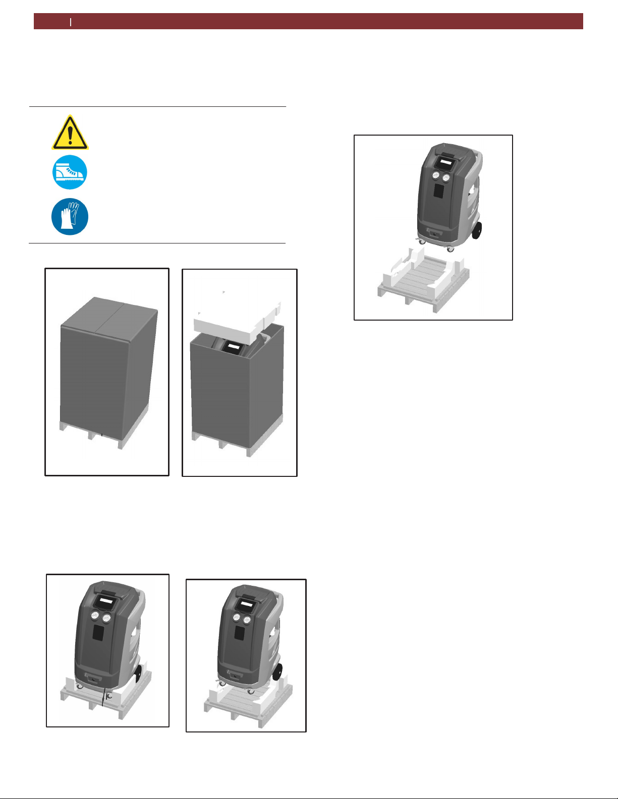
Remove staples and remove the carton (Fig. 10)
Slowly lower the unit from pallet by means of the rear
Fig. 12: Lowering unit from the pallet
wheels (Fig. 12).
Keep the pallet, carton, and scratch protection film for use in
case of a need to return unit.
Fig. 10: Removing carton
Cut straps securing unit to pallet.
With 2 people, lift both front wheels by levering with the
handle so unit is setting on the rear wheels (Fig. 11).
Fig. 11: Tilting unit backwards
1901016-85
Page 16
7 Commissioning
All the operations described in Section 7 must be
t
performed prior to first A/C service
7.1 Connections and positioning
The AC442 is designed for 110V, 50/60Hz.
m
Follow the information on the AC442 rating
plate.
1 Set the AC442 on a flat, vibration proof surface.
2 Actuate the caster brake to stop the AC442 from rolling.
3 Connect the power supply cable to the power supply.
4 Switch on the main switch.
The unit must be positioned on a stable, horizontal
m
surface to ensure correct operation. Unit must be in an
area with proper ventilation and at least 10cm from
any potential obstacle to
Keep unit out of rain and excessive humidity as
moisture could cause irreparable damage.
its internal ventilation.
Prevent exposure to direct sunlight and excessive dust.
m
m
Unit must be properly grounded with the power plug
ground
constitutes
t
Do not unplug any internal electrical connections and
only
by trained
t
Contact customer service in the event of any transportation
damage (e.g. oil leakage).
t
Leave quick couplings closed when unit is not in use and
at end of vehicle service operations.
pin. Failure to ground unit can cause damage and
a
risk of fatal injury or shock to the operator.
have internal components opened and repaired
customer service personnel.
Commissioning | AC442 | 16 en
7.2 First start-up verification
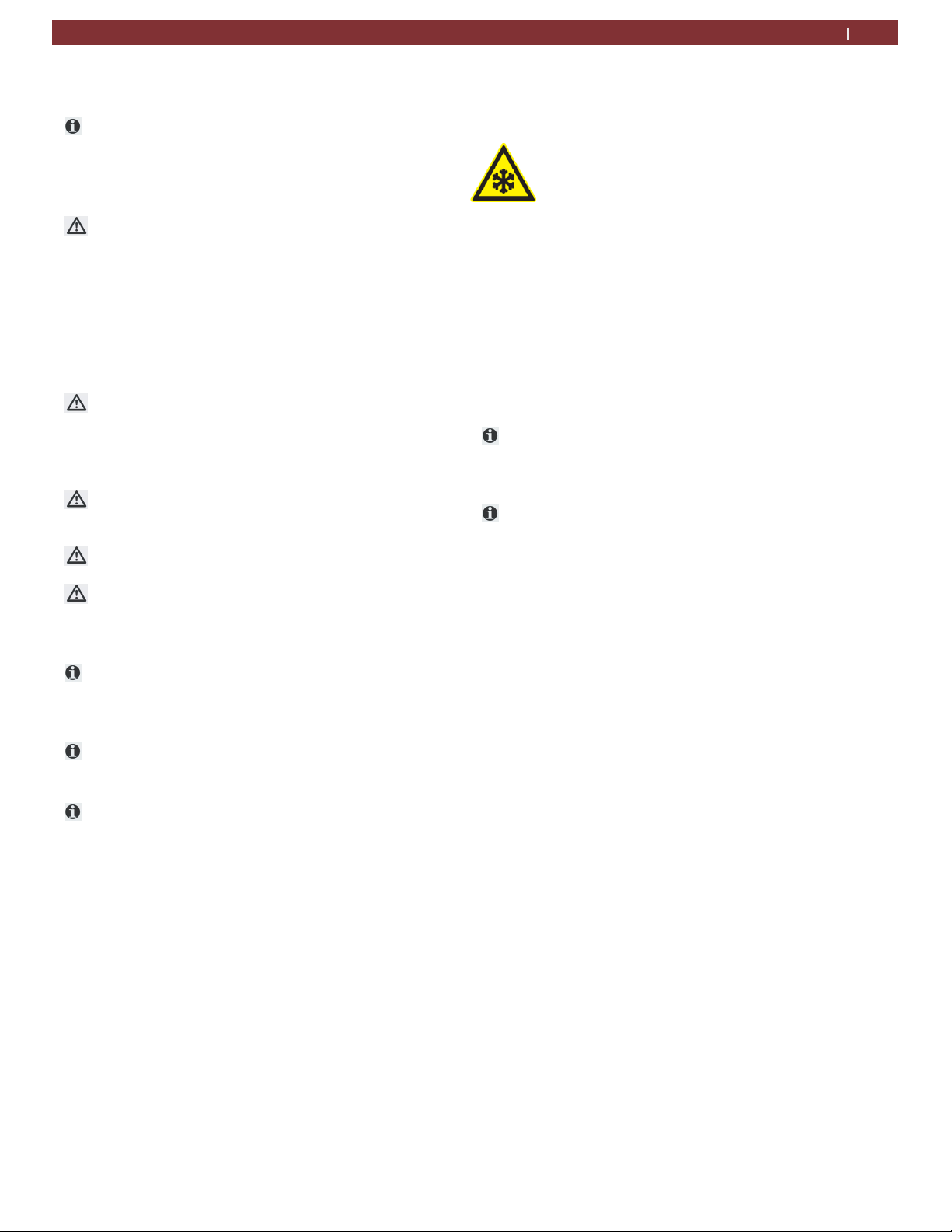
Warning – Risk of frostbite from
escaping refrigerant
Refrigerant causes frostbite on the skin
Check the service hoses for damage
Firmly connect the service quick-
release couplings to the service
hoses.
Wear protective goggles.
Wear protective gloves.
Execute the following actions in sequential order by
following the procedure as shown on the display:
—
Gas weight check (vacuums entire
refrigerant circuit to ensure no
contaminants are in system prior
to filling
—
First internal cylinder fill
It is possible to interrupt the initial check and print a
o
report in which the status of the check is reported (if
printer option
was purchased).
t
Equipment cannot operate in automatic mode until all
steps of initial check are completed.
the
1.
Set the internal cylinder fill to desired quantity (min. 3kg).
2.
Follow on-screen instructions.
3.
Make sure hoses are disconnected from any external
source at this time.
4.
Start the procedure that initially creates vacuum in the
internal refrigerant circuit (approximately 15 minute
process).
5.
Once message is displayed, the unit can be connected
to the external cylinder and the valves opened.
6.
Just before the targeted refrigerant amount is
reached, unit will pause and prompt user to close
external refrigerant tank connection.
7.
Once this is done, the unit will continue to recover the
refrigerant from the hoses and end once this is
completed. The total amount recovered will then be
displayed.
1901016-85
Page 17
en
17| AC442 | A/C System service
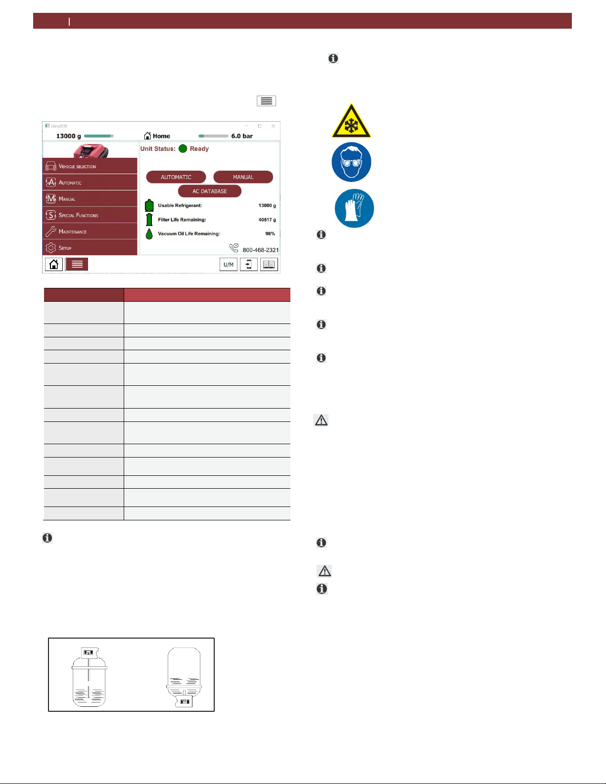
7.3 Setup
From the SETUP menu, it is possible to enable/disable and
set certain parameters prior to performing A/C system
service. To access SETUP from the main menu, press,
and the SETUP menu will be displayed
Parameter Description
Wi-Fi
Print Provide print options
Update Allows software updating
Brightness Adjustment of screen backlight
Maintenance
Counters
Units of
measurement
Account User information definitions
Language
Remote Control Used for remote tech service diagnostics
System
Information
Date and Time Adjustment of date and time
Settings
Configure Password protected service information
Check the type of source tank, 2 types are available:
Allows connection to wireless internet
access
Displays historical unit information
Allows metric and empirical unit changes for
all unit parameters
Allows adjustment of user language on
display
Displays all internal system information
Allows enable and disable for selected
functions
.
— Refrigerant cylinder with plunger (typically 2
valves):
Connect to the liquid valve and keep tank in the
upright position to transfer refrigerant.
— Refrigerant cylinder without plunger (single
valve):
Connect to the available valve and invert tank to
transfer refrigerant.
Fig. 13: Virgin refrigerant cylinder tank types
The LP (blue) gauge indicates the pressure inside the
external cylinder
7.4 Internal Bottle Fill
Check the service hoses for damage.
Firmly connect the service quick-release
Wear protective goggles.
Wear protective gloves.
Before the AC442 can be used, the internal refrigerant
bottle must be filled with liquid refrigerant. Use only
R134a refrigerant.
A menu-driven refrigerant check is performed before
filling the internal refrigerant bottle.
The refrigerant can be obtained from your gas supplier. It
can be stored normally and transported in bottles with
connection fittings.
To ensure a reliable procedure, it is advisable to use the
optimum quantity of refrigerant. The optimum quantity
of refrigerant for the ACX2250 is 4kg – 9.5kg.
An inadequate quantity may make efficient filling of the
vehicle air conditioning system impossible. Also, if there
is an insufficient quantity, the ACX2250 may not be able
to operate efficiently. In the event of an excessive
quantity, there may not be sufficient space for the
refrigerant recovered from the vehicle air conditioning
system.
Generally speaking, the actual quantity of refrigerant
added exceeds the set quantity by approx. 200g as there
is no refrigerant in the internal refrigerant circuit. Add
200g to the set quantity when filling with refrigerant for
the first time.
1. Select "Maintenance>>Internal bottle fill".
2. Follow the menu prompting.
The current pressure inside the external refrigerant bottle
is indicated on the low-pressure gauge.
Any amount of refrigerant between 200g and 10500g can
be added.
Do not interrupt the automatic filling process prior to
automatic termination by the AC442.
Press the Home key to check the quantity of refrigerant in
the internal refrigerant bottle upon completion of the
filling operation.
Warning – Risk of frostbite from
escaping refrigerant
Refrigerant causes severe frostbite
on the skin.
couplings to the service hoses.
1901016-85
Page 18
8 A/C service preparation
8.1 Preliminary preparation
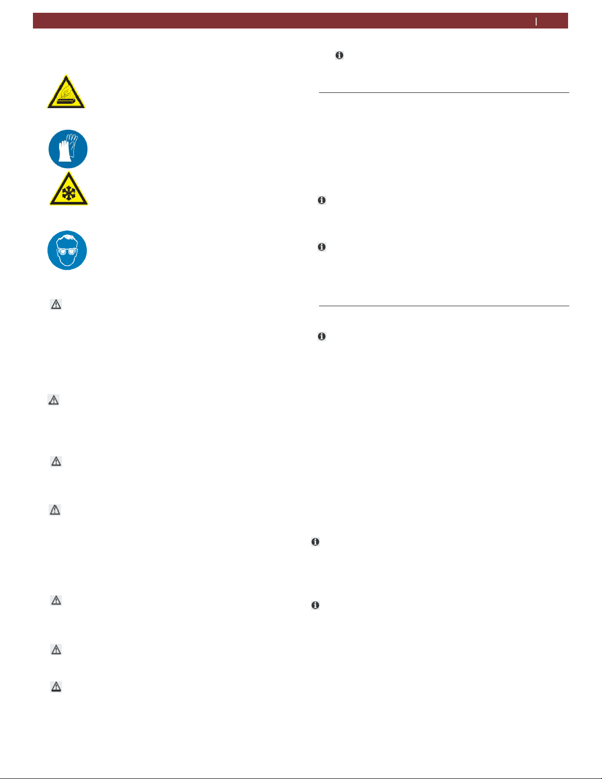
Warning - risk of burns from hot
engine
Contact with hot engine
components will cause severe
burns.
Warning - risk of frostbite from
escaping
Refrigerant causes frostbite on the
skin.
Perform the following preparatory work prior to
vehicle A/C service: Service hoses must be
constructed of the proper materials and have the
lengths as supplied by the unit. Hoses must have
shut-off devices (quick-release couplers) at the
connection point to the A/C to minimize the
introduction of air into the AC442 and to minimize the
amount of refrigerant released while disconnecting
the hoses.
Inspect hoses for signs of damage prior to
performing A/C service. Use of damaged hoses will
result in the loss of refrigerant and the possibility of
refrigerant contamination.
Follow the vehi cle manufacturer's r ecommendations
for A/C
connection only.
A/C service operations (especially recovery) should be
performed after the vehicle has been run for a period
of time to
This allows for the
amount to occur. If system is excessively hot, the
recharge phase could be adversely effected
The AC442 is only to be operated with R134a
refrigerant. Check with refrigerant is used for the
vehicle before performing A/C service.
Never attempt to close the valves of the internal
refrigerant bottle while the AC442 is in operation.
Only new lubricant as specified by the system
manufacturer shall be installed in vehicle A/C system.
Lubricant removed from the system and or equipment
shall be disposed of in accordance with the applicable
federal, state and local procedure and regulations.
service on vehicles with a low-pressure
allow engine heat to raise system pressure.
components
Allow the engine to cool down.
Wear protective goggles.
Wear protective gl oves.
refrigerant
Check the service hoses for damage.
Firmly connect the service quick-
release couplings to the service
hoses.
Wear protective goggles.
Wear protective gl oves.
maximum refrigerant recovery
A/C System service
The service parameters (recharge quantity) can be
found in the owner's manual or the vehicle repair
manual.
8.2 Non-condensable gas discharge
| AC442 | 18
en
If the AC442 detects non-condensable gases in the
internal cylinder, the unit will prompt technician to
allow unit to run an air purge. This prompt will occur
every time unit is powered on (if unit has been
powered off for at least 1 hour.)
The process will perform automatically upon the
start of a charge procedure if non-condensables are
detected.
Air purge is a necessary process to ensure ideal working
parameters for the AC442. Presence of non-condensable
gases will increase tank pressure and reduce efficiency of
recharge cycles.
8.3 Charge Modes
The AC442 has 2 different refrigerant charge
methods. If charge does not complete using Quick
mode, the zero tolerance method automatically
commences
8.3.1
Quick Modes
In Quick mode, the AC442 injects refrigerant through HP port.
The refrigerant remains in the hoses at the end of the cycle
and is then recovered during a hose clearing process.
8.3.2
.
Zero tolerance mode
While the Zero tolerance mode is slightly longer in time, it
provides a more accurate recharge and guarantees a
successful charge.
In Zero tolerance mode, the AC442 will by default charge
through the HP (red) hose, then refrigerant that remains in
the hoses is pulled into the vehicle's A/C system through the
LP (blue) hose.
In the instance where only a LP coupling is available for
A/C service, the AC442 will charge the system with 50%
of the total charge amount with the vehicle A/C
compressor off. The unit then waits 10 minutes to allow
the liquid refrigerant to evaporate to prevent damage to
the compressor. The vehicle must be started and the A/C
system turned on. The AC442 will continue to charge the
refrigerant whenever the LP hose pressure is less than 3
bar.
1901016-85
Page 19
en
19| AC442 | A/C System service
9 A/C system service
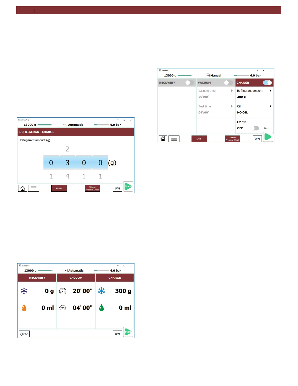
9.1 Automatic cycle setup
Access to automatic cycles is available through the
main menu by selecting AUTOMATIC.
Do not connect hoses/couplers to vehicle A/C system
until prompted by the unit.
All values in the AUTOMATIC cycle mode are preset
and unable to be modified from the Automatic menu,
except for the refrigerant charge amount. If changing
the value of the vacuum amount is desired, select a
MANUAL process and choose all 3 services to be
performed.
1. From the main menu, select AUTOMATIC.
2. Adjust the charge value to match that of the vehicle
manufacturer’s recommended value.
Fig. 14: Adjusting charge value
3. To change which hose the unit will charge, touch the
blue box at the bottom of the screen that says LP-HP. A
menu will pop up that allows technician to select which
hoses/couplers to charge through.
4. If the technician wishes to perform a pressure check of
the A/C system, they should select Vehicle Pressure
check at the bottom of the screen. (When highlighted
BLUE, the pressure check function is selected; when in
GREY, the unit will not perform a pressure check.)
5. After options are properly adjusted, press the green
9.2 Manual cycle setup
Access to manual cycles is available through the main menu
by selecting MANUAL CYCLES.
Do not connect hoses/couplers to vehicle A/C system until
prompted by the unit.
1. From the main menu, select MANUAL.
Fig. 16: Manual setting selection
2. Select the services desired by touching button at the
upper right corner of each column. (Figure shows charge
service selected)
See the sections about Recovery, Vacuum, and Charge on
the next page for more detailed cycle setting information.
3. To change the charge hose, touch the blue box at the
bottom of the screen that says LP-HP. A menu will pop
up that allows technician to select which hoses/couplers
to charge through.
4. If the technician wishes to perform a pressure check of
the A/C system, they should select Pressure check at the
bottom of the screen. (When highlighted BLUE, the
pressure check function is selected; when in GREY, the
unit will not perform a pressure check.)
5. After options are properly adjusted, press the green
arrow in the lower right corner of the screen.
6. The unit will display a screen to confirm process
settings. Press the START button to begin process.
7. Follow on-screen instructions to complete cycle.
arrow in the lower right corner of the screen.
Fig. 15: Automatic setting confirmation
6. If settings are correct, press START button to begin
process
1901016-85
Page 20
9.3 Recovery process
1. From the main menu, select MANUAL, and then
deselect all options except for RECOVERY.
2. To change the service hose, touch the blue box at the
bottom of the screen that says LP-HP. A menu will pop
up that allows technician to select which hoses to
perform service through.
3. Press green arrow in lower right corner to begin
service.
4. Follow on screen instructions to begin recovery
process.
If no pressure is detected in the system, this function will
not start. Technician should ensure couplers are open. If
the system is empty, operator must exit and select a
vacuum process.
There is potential for unit to display an error during this
service for high internal pressure. This can occur due to
high operating temperatures or hot refrigerant gasses
entering the AC442
9.4 Vacuum process
1 From the main menu, select MANUAL, and then
deselect all options except for VACUUM.
2 To change the service hose, touch the blue box at the
bottom of the screen that says LP-HP. A menu will pop
up that allows technician to select which hoses to
perform service through.
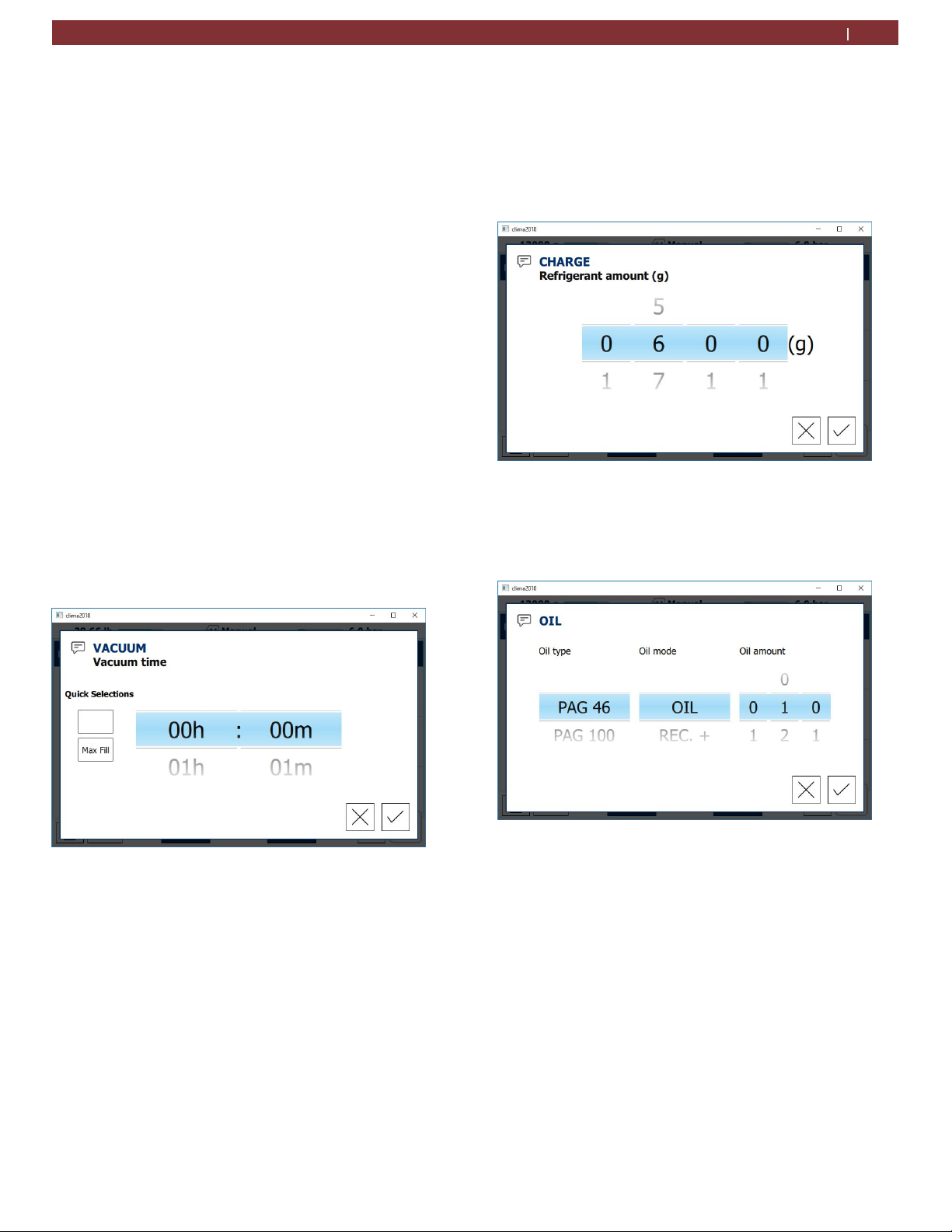
3 To adjust vacuum time, touch in the VACUUM TIME
box. The screen in Figure below will appear.
A/C System Service
| AC442 | 20
en
9.5 Charge process
1. From the main menu, select MANUAL, and then deselect all
options except for CHARGE.
2. To change the service hose, touch the blue box at the bottom
of the screen that says LP-HP. A menu will pop up that allows
technician to select which hoses to perform service through.
3. To adjust Charge amount, touch in the REFRIGERANT
AMOUNT box. The screen in Figure below will appear.
Fig. 18: Charge amount adjustment
4. Swipe finger up or down to adjust the refrigerant value to the
vehicle manufacturer’s recommended value, then press the
to accept or the X to cancel time adjustment.
5. Then click the Oil amount box to adjust oil amount and type.
Fig. 17: Vacuum time adjustment
4 Swipe finger up or down to adjust the hours and
minutes, then press the
time adjustment.
5 If the vacuum test time needs adjusted, touch in the
TEST TIME box.
6 Press green arrow in lower right corner to begin
service.
7 Follow on screen instructions to begin vacuum
process
to accept or the X to cancel
1901016-85
Fig. 19: Oil amount adjustment
6. Swipe finger up or down to adjust the oil values, then press
the
to accept or the X to cancel oil value adjustments.
7. If desired, turn the Tracer injection on to inject UV Dye into
the vehicle A/C system.
8. Press the green arrow in lower right corner to begin service.
9. Follow on screen instructions to complete charge process.
Page 21
en
21| AC442 | A/C System service
9.6 Flushing after changing type of Oil
When servicing a vehicle, the type of oil in the vehicle's
A/C system should be noted to prevent a crosscontamination inside the AC440. If a PAG system is
serviced and another vehicle with a POE system is to be
serviced next, a flush routine must be performed to
prevent a cross-contamination of the oils.
If the AC440 is not flushed the internal hydraulic system
and the vehicle air conditioning system could be
damaged as a result of cross-contamination. MATCO
cannot accept liability for any such damage.
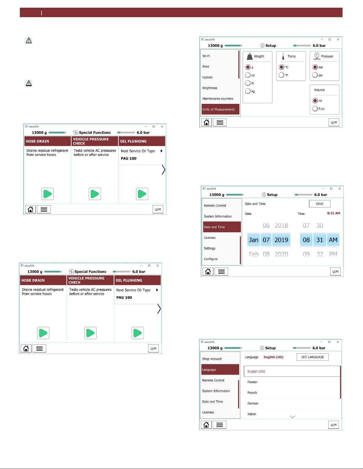
1. From the MENU, scroll to SPECIAL FUNCTIONS and
select. The SPECIAL FUNCTIONS screen will now be
displayed.
Fig. 22: Oil Flushing
2. Follow the menu prompting to complete oil flushing.
9.7 V
ehicle Pressure Check
1. From the MENU, scroll to SPECIAL FUNCTIONS and
select. The SPECIAL FUNCTIONS screen will now be
displayed.
Fig. 23: Vehicle pressure check
2. This will test vehicle A/C pressures before and after service
9.8 Unit of measure
1.
From the SETUP menu, scroll to UNITS OF MEASURE.
2.
The user has the option of selecting the units of
measure for:
Weight
Temperature
Pressure
Volume
Fig. 24: Unit of measure
9.9 Clock
Adjustment
1. From the SPECIAL FUNCTIONS menu, scroll to SET UP
and select DATE and TIME .
2. The operator can now scroll to the desired date and
time settings.
3. After selection is complete, press save.
Fig. 22: Clock Adjustment
9.10 Setting language
1. From the SETUP menu, scroll to LANGUAGE
2. The user now has the option of seven language
selections.
3. Scroll to the desired language and select.
4. Press SET LANGUAGE to save your selection.
Fig. 23: Language
1901016-85
Page 22
Maintenance
| AC442 | 22
en
10 Maintenance
Please contact an authorized technical service
center for purchasing factory replacement parts.
10.1 Maintenance interval
Description Period
Calibration of scales
Vacuum pump oil replacement and
system leak test
Combo filter replacement and system
leak test
System leak test
1x per year to ensure accuracy
m
Make sure AC442 is disconnected from power before
removing plastic housing.
Never perform any maintenance work which is not
expressly
recommended in this Section.
Contact customer service if components have to be
m
replaced
other than in the course of maintenance work.
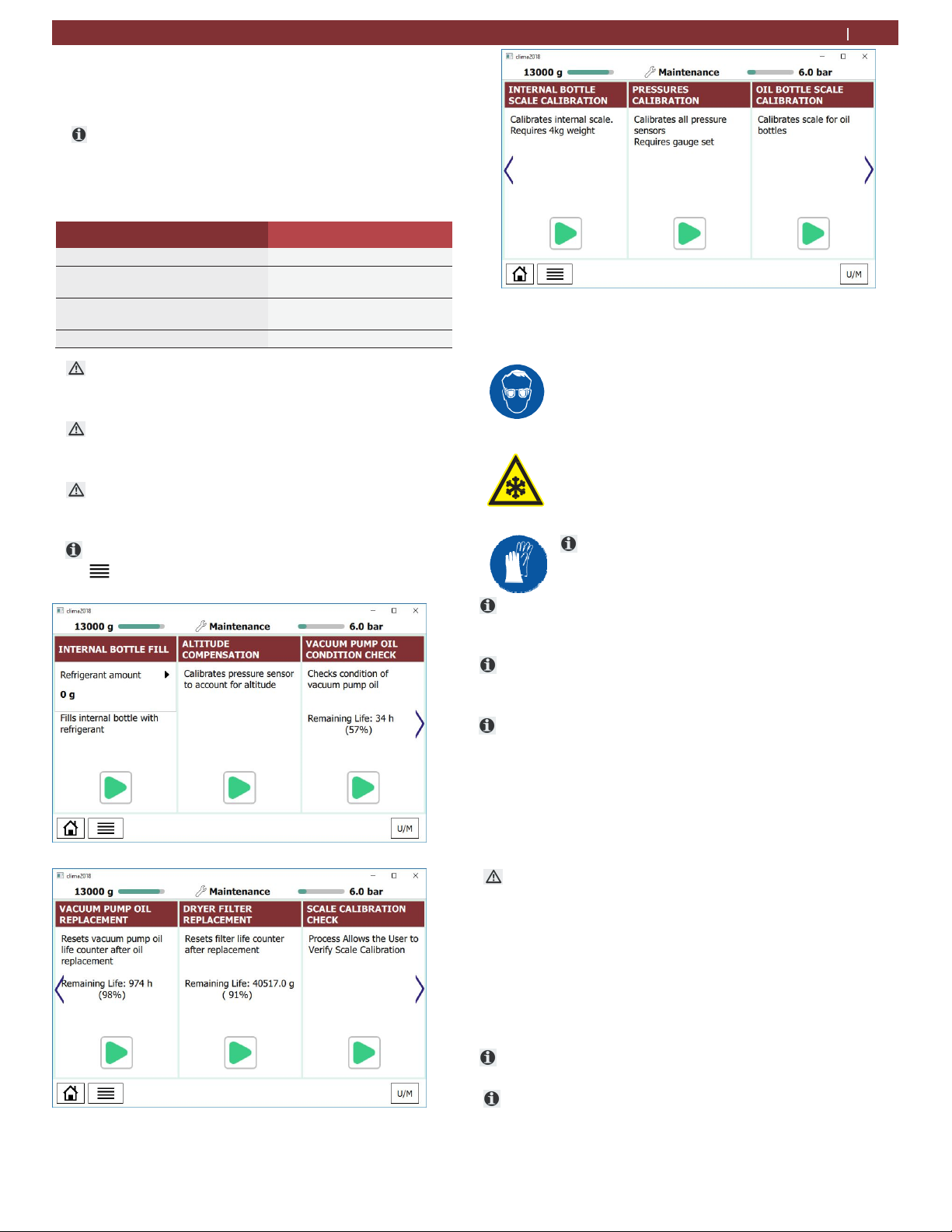
To access MAINTENANCE from the MAIN MENU, press
and s
croll to MAINTENANCE and then select.
After 1000 hours of service
After 75kg of refrigerant
processed
As required
Fig. 25: Maintenance screens
10.2 Filling internal refrigerant cylinder
Warning - Risk of frostbite from
escaping
Refrigerant causes severe frostbite on the
skin.
Check the service hoses for damage.
Firmly connect the service quick-release
couplings to the service hoses.
Wear protective goggles.
Wear protective gloves.
refrigerant
Before the AC442 can be used, the internal
refrigerant
refrigerant. Use only R134a refrigerant.
t
The refrigerant can be obtained from your gas supplier. It
can be stored normally and transported in bottles with
connection fittings
t
To ensure a reliable procedure, it is advisable to use
optimum quantity of refrigerant. The optimum
the
quantity of
refrigerant for the AC442 is 4kg – 10.0kg.
cylinder must be filled with liquid
An inadequate quantity of refrigerant may make
effectiveness of filling the vehicle air conditioning
system impossible. Also, if there is an insufficient
quantity, the AC442 may not be able to operate
efficiently. In the event of an excessive quantity, there
may not be space for the refrigerant recovered from
the vehicle air conditioning system.
Do not open coupler until unit prompts technician to open.
m
1.
From the MAINTENANCE menu, scroll until
INTERNAL BOTTLE FILL is highlighted and press.
2.
To adjust the charge amount, highlight the value and press to
adjust the value higher or lower.
3.
Press the to accept and begin process. or the X to cancel
adjustment.
4.
Follow the menu prompting.
t
The current pressure inside the external refrigerant
bottle is
Do not interrupt the automatic filling process prior to
automatic
indicated on the low-pressure gauge.
termination by the AC442.
-
Page 23
en
23| AC442| Maintenance
10.3 Self test
t
This test is designed to check the internal AC442 circuit for
any leaks.
To perform Self test:
1.
From th e MAINTENANCE menu, scroll until SELF TEST
is highlighted and press.
2.
Allow unit to perform test to completion.
If a test fails, check charge hoses and quick couplers for
leaks first. If repair is possible, fix the leak and repeat
test.
10.4 Pressure zero
This function allows technician to determine and store the
atmospheric pressure value.
This procedure should be performed everytime the
AC442 is moved from one location to another that has
a different altitude
1. From the MAINTENANCE menu, scroll until PRESSURE
ZERO is highlighted and press arrow.
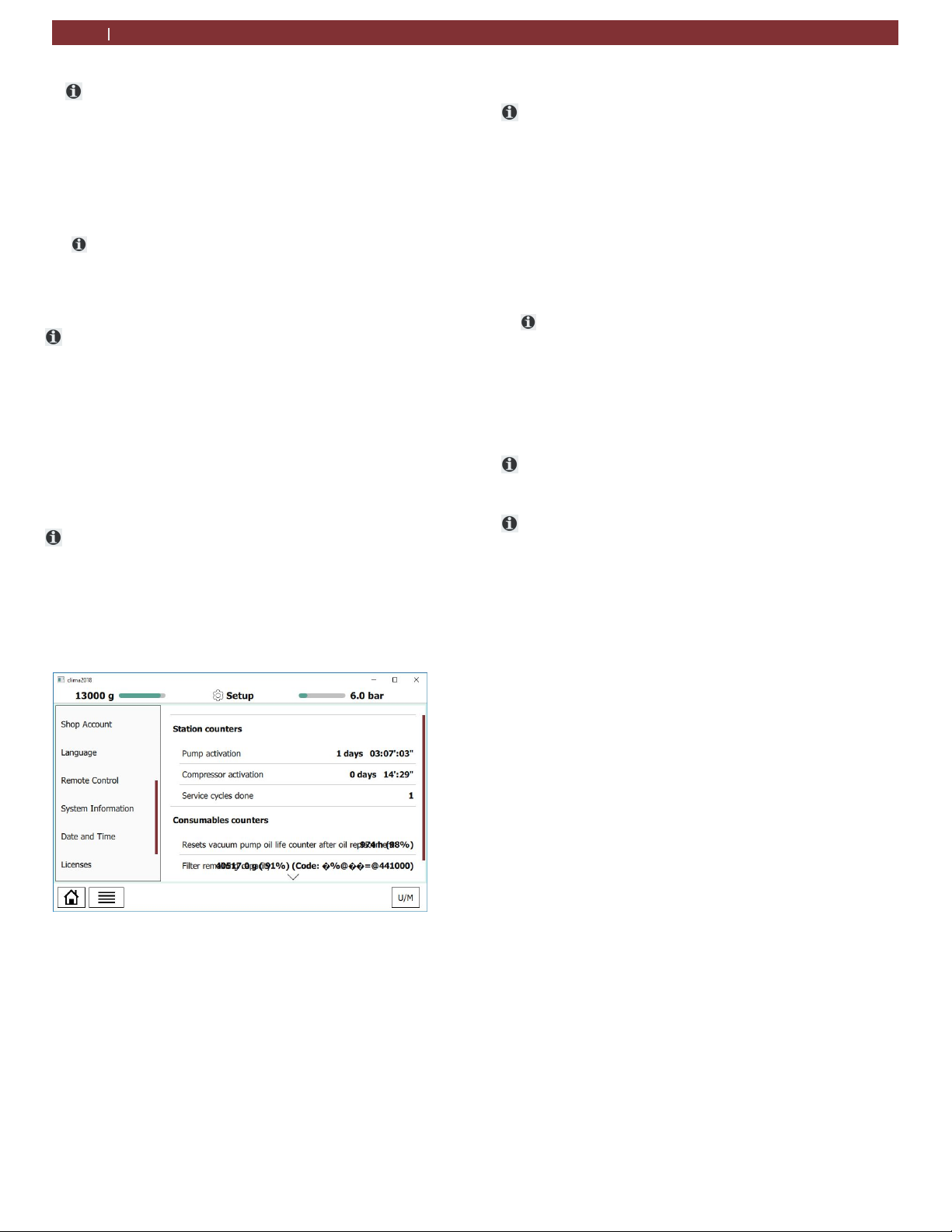
10.5 Counters
These screens will display the vacuum pump and
compressor hours of life and the remaining time before
vacuum pump oil and the filter dryer need replacement.
1.
From the MAINTENANCE menu, scroll u ntil
MAINTENANCE COUNTERS is shown and make selection.
2.
Press to display all counters.
Fig. 26: Maintenance counters
10.6 Long life pump test
The Long Life Pump function equipped on the AC442
enables the unit to optimize the vacuum pump oil use and
avoid the need to replace after every 60 hours of operation.
1.
After the first 60 hours of vacuum pump operation, check
the vacuum pump oil level and top off if necessary.
2.
From the MAINTENANCE menu, scroll until LONG
LIFE PUMP TEST is highlighted and press arrow.
3.
The process will run for approximately 1 hour.
During this process, the vacuum pump oil is automatically
purified from the gaseou s residues absorbed by the oil
during
4.
At end of procedure, vacuum pump performance check is
executed and the result is di splayed on the display.
If the result of the Long Lif e Pump test is negative, the oil
must be changed.
If the results pass, the pump oil remaining time will change
to 1000 hours. After 1000 hours of runtime, the oil must be
changed.
the vacuuming of vehicle A/C systems.
1901016-85
Page 24
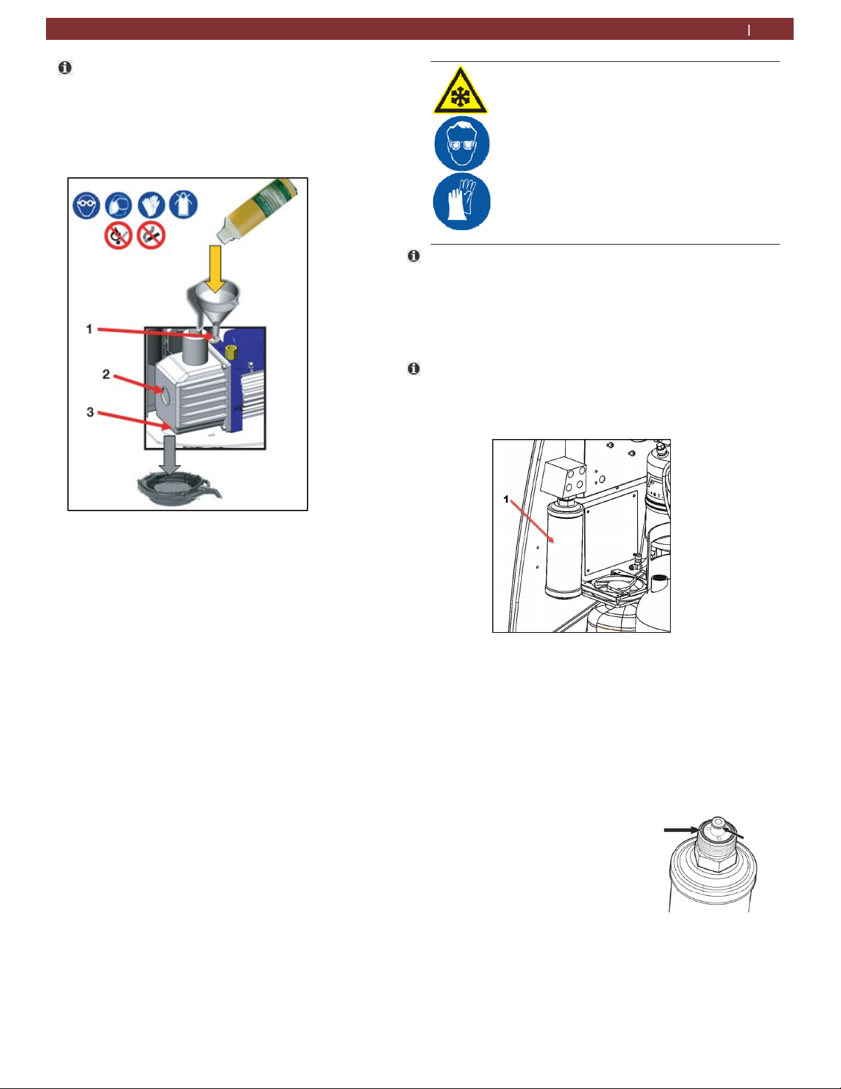
10.7 Vacuum pump oil change
After 60 hours of runtime (or 1000 hours if the
Long Life
the vacuum pump oil
Pump test is completed successfully),
must be replaced.
1.
Disconnect AC442 from power.
2.
Using a flathead screwdriver, rotate the front locking
screw and lift the front housing.
Fig. 27: Changing vacuum pump oil
1
Oil filling plug
2
Oil inspection window
3
3.
4.
5.
6.
7.
8.
9.
Lower drain plug
Place a bowl under the vacuum pump oil drain hole.
Remove the upper filling plug and the lower drain
plug to allow the oil to drain from unit.
Once the pump has been emptied, reinstall the lower
drain plug.
Fill the pump with new oil through the upper fill port
using a funnel if needed. Fill until the oil appears
halfway up the oil level inspection window.
Once the pump has been filled, reinstall the upper fill
plug.
Close front housing and secure locking screw.
Connect to power and turn on.
From the MAINTENANCE menu, press until
PUMP OIL
press arrow. Press the RESET key to set the counter.
The level and clearness of the vacuum pump oil can
be checked by removing the rubber plug located on
the front-left side of the unit.
REPLACEMENT is highlighted and
Maintenance
10.8 Replace filter dryer
Warning - Risk of frostbite from escaping
refrigerant
Refrigerant causes severe frostbite on the
skin.
Check the service hoses for damage.
Firmly connect the service quick-release
couplings to the service hoses.
| AC442 | 24
en
Wear protective goggles.
Wear protective gloves.
Unit operation is disabled at the end of the filter service life.
Each filter is marked with a unique code. This code must be
entered when replacing the filter. It is not possible to
operate the AC442 if the same code is re-used. It is
advisable to keep a supply of filters in stock to avoid
downtimes due to the unit being disabled.
The AC442 is disabled once 90kg (198lb) of R134a
refrigerant has passed through the filter. A new filter must
be installed and its unique code entered in the AC442 before
vehicle A/C service can be performed.
Fig. 28: Changing filter dryer
1
Filter dryer
1.
To begin the f i lter replacement process, from the
MAINTENANCE menu, scroll until FILTER REPLACEMENT
is highlighted and press arrow .
2.
Insert the new filter code using the keypad.
3.
Using a flathead screwdriver, rotate the front locking screw and
lift the front housing.
4.
Verify that the 2 o-rings are included and positioned correctly
prior to attaching to housing.
5.
Loosen the filter using a 1-3/8”
(35mm) wrench.
6.
Remove the filter
7.
Insert a new filter
8.
Tighten the filter to 74 ft-lbs (100N-
m)
9.
Carefully close front housing and
secure locking screw.
10.
Allow unit to perform the
automatic leak test requested by the software when unit loads
1901016-85
Page 25
en
25 | AC442 | Maintenance
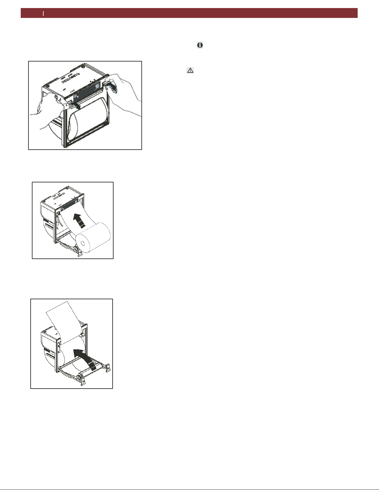
10.9 Printer maintenance (optional)
1.
Open the lid of the printer as shown in Fig. 28.
Fig. 29: Opening printer
2.
Position the roll of paper inside the housing in the
rotation direction indicated in Fig. 29.
Fig. 30: Installing new paper roll
3.
Pull the paper out of the housing as shown in Fig. 30
and close the lid.
Fig. 31: Completing Installation
4.
The printer is ready for printing
10.10 Periodic checks
The AC442 service station must be checked over
regularly as set by local legislation.
The following checks should be performed to ensure safe
and reliable operation:
— Make sure no corrosion or leakage is present in the
internal cylinder and other metallic parts of the
equipment (under normal conditions the internal
cylinder life is at
least 20 years).
— If automatic safety valve trips, contact technical support
to have unit inspected, resolve any issues and
replace valve if necessary.
— If the safety pressure switch trips, check the connection
of the cables and correct connection to the PCB.
Contact technical support for additional assistance.
— Check that external charging hoses - both red (HP) and
blue (LP) - are in good order and undamaged. In the
of damaged hoses, discontinue use of AC442
case
until
replacement hoses are procured.
— Verify that vacuum pump oil and filter dryer have been
replaced according to schedule for proper functioning
equipment.
1901016-85
Page 26
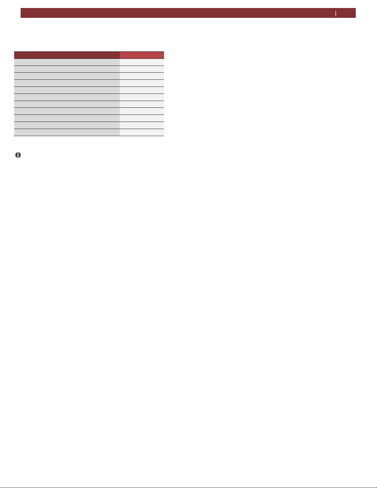
Spare parts | AC442 | 26 en
11 Spare parts
Description Order number
Combo filter AC83254
Vacuum pump oil AC80070
Paper for printer (5 rolls) AC83110
Service hose (HP) AC80532
Service hose (LP) AC80533
Quick release coupling (HP) AC80495
Quick release coupling (LP) AC80496
Safety goggles (accessory item) AC82956
Protective gloves(accessory item) AC82957
Adaptor LP (external bottle) USACME1/2 AC80147
Calibration Check Ball AC82744
Additional spare/replacement parts are available
through the service centers authorized by MATCO or by
its reseller. Contact technical support for replacement
parts not listed above.
1901016-85
Page 27
en
27 | AC442 | Maintenance
12 Maintenance
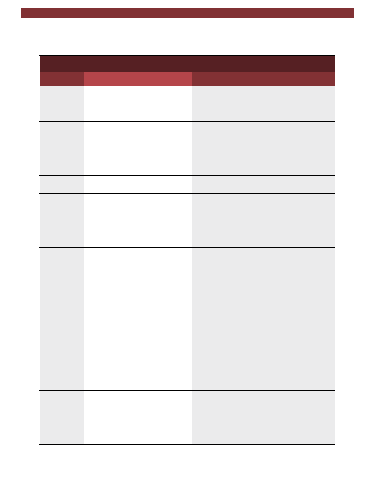
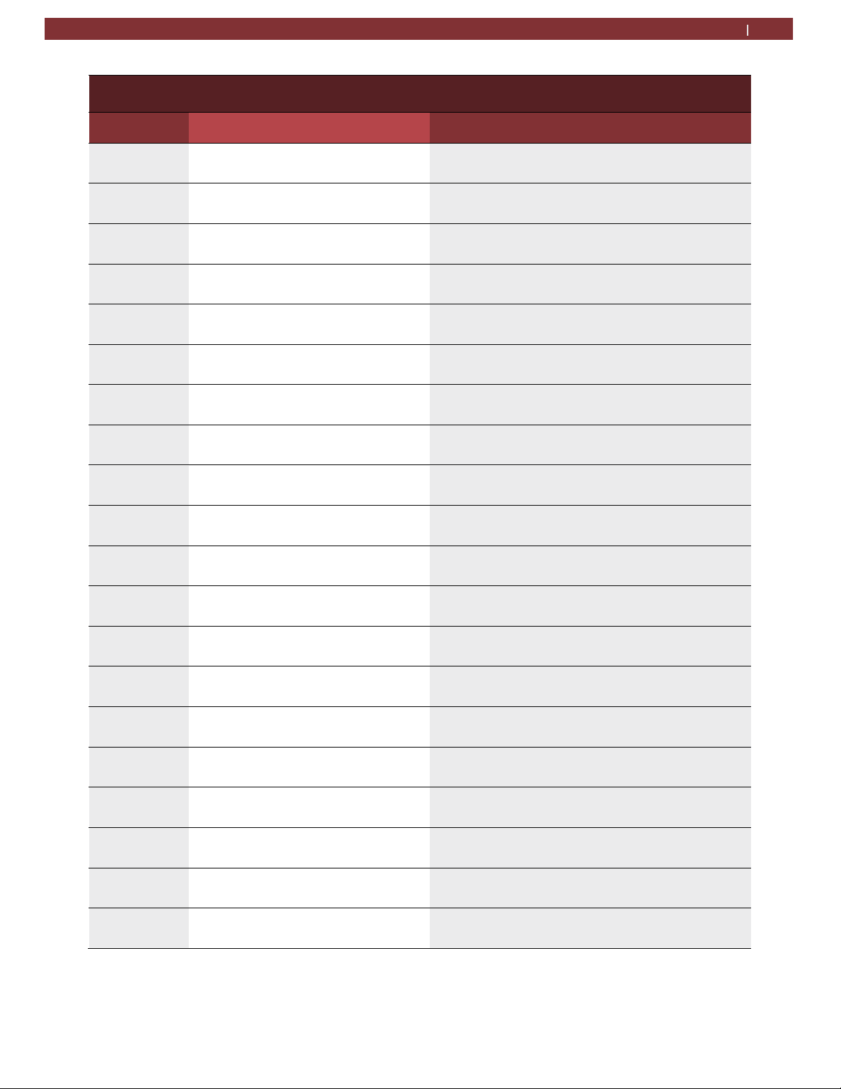
12.1 Vacuum pump oil change
Date Maintenance technician identification Maintenance technician signature and stamp
Vacuum pump oil change record
1901016-85
Page 28
Maintenance | AC442 | 28 en
Vacuum pump oil change record
Date Maintenance technician identification Maintenance technician signature and stamp
-
Page 29
en
29 | AC442 | Maintenance
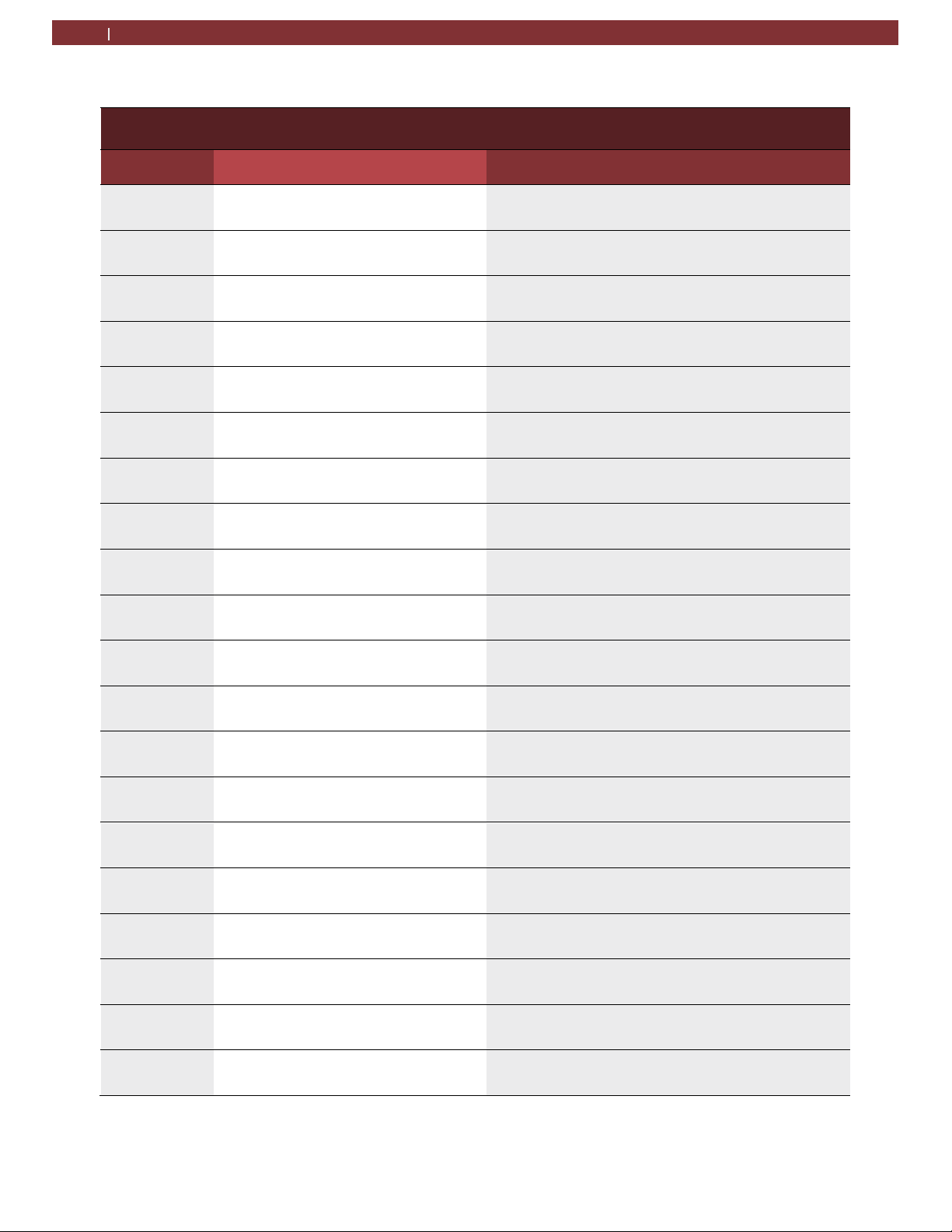
12.2 Filter dryer change
Date Maintenance technician identification Maint. Tech. signature and stamp
Filter Dryer Change Record
1901016-85
Page 30

Maintenance | AC442 | 30 en
Filter Dryer Change Record
Date Maintenance technician identification Maint. Tech. signature and stamp
-
Page 31

en
31 | AC442 | Maintenance
Filter Dryer Change Record
Date Maintenance technician identification Maint. Tech. signature and stamp
1901016-85
Page 32

12.3 Refrigerant load cell calibration check
Refrigerant Load Cell Calibration Check Record
Maintenance | AC442 | 32 en
Date
Result of check
(pass/fail)
Maintenance technician identification Maintenance technician signature and stamp
-
Page 33

en
33 | AC442 | Maintenance
12.4 Other checks/maintenance/repairs
Other checks/maintenance/repairs
Job Date
Result of check
(pass/fail)
Maintenance technician identification
Maintenance Technician
signature and stamp
1901016-85
Page 34

Maintenance | AC442 | 34 en
Other checks/maintenance/repairs
Job Date
Result of check
(pass/fail)
Maintenance technician identification
Maintenance Technician
signature and stamp
1901016-85
Page 35

en
35 | AC442 | Maintenance
12.5 Notes
1901016-85
Page 36

1901016-85
035 82688 00 (REV A)
2019-05-01
 Loading...