

Page 1
deutsch / english
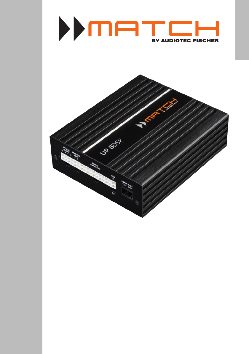
UP 8DSP
UPGRADE
8-Kanal Upgrade-Verstärker mit integriertem
9-Kanal 64 Bit DSP für universelle Anwendungen
8-channel upgrade amplier with integrated
9-channel 64 Bit DSP for universal applications
Page 2

Page 3

Herzlichen Glückwunsch!
de
Sehr geehrter Kunde,
wir gratulieren Ihnen zum Kauf dieses hochwertigen
MATCH Verstärkers mit integriertem DSP.
MATCH setzt mit dem UP 8DSP neue Maßstäbe im
Bereich der Verstärkertechnik. Dabei protieren Sie
als Kunde direkt von unserer mehr als 30-jährigen
Erfahrung in der Forschung und Entwicklung von
Audiokomponenten.
Allgemeine Hinweise
Allgemeines zum Einbau von MATCH-Komponenten
Um alle Möglichkeiten des Produktes optimal ausschöpfen zu können, lesen Sie bitte sorgfältig die
nachfolgenden Installationshinweise. Wir garantieren, dass jedes Gerät vor Versand auf seinen einwandfreien Zustand überprüft wurde.
Vor Beginn der Installation unterbrechen Sie
den Minusanschluss der Autobatterie.
Wir empfehlen Ihnen, die Installation von einem
Einbauspezialisten vornehmen zu lassen, da der
Nachweis eines fachgerechten Einbaus und Anschlusses des Gerätes Voraussetzung für die Garantieleistungen sind.
Dieser Upgrade-Verstärker wurde von uns nach
neuesten technischen Erkenntnissen entwickelt und
zeichnet sich durch hervorragende Verarbeitung
und eine überzeugende Anwendung ausgereifter
Technologien aus.
Viel Freude an diesem Produkt wünscht Ihnen das
Team von
AUDIOTEC FISCHER
den. Achten Sie bitte darauf, dass sich solche Teile
auch in der doppelten Wandverkleidung verbergen
können.
Allgemeines zum Anschluss des UP 8DSP
Verstärkers
Der Verstärker darf nur in Kraftfahrzeuge eingebaut
werden, die den 12 V-Minuspol an Masse haben.
Bei anderen Systemen können der MATCH Verstärker und die elektrische Anlage des Kfz beschädigt
werden. Die Plusleitung für die gesamte Anlage
sollte in einem Abstand von max. 30 cm von der
Batterie mit einer Hauptsicherung abgesichert werden. Der Wert der Sicherung errechnet sich aus der
maximalen Stromaufnahme der Car-Hi Anlage.
Installieren Sie Ihren Verstärker an einer trockenen
Stelle im Auto und vergewissern Sie sich, dass
der Verstärker am Montageort genügend Kühlung
erhält. Montieren Sie das Gerät nicht in zu kleine,
abgeschlossene Gehäuse ohne Luftzirkulation oder
in der Nähe von wärmeabstrahlenden Teilen oder
elektronischen Steuerungen des Fahrzeuges.
Im Sinne der Unfallsicherheit muss der Verstärker professionell befestigt werden. Verwenden
Sie hierzu die zwei im Lieferumfang enthaltenen
Montagebleche. Diese werden mit jeweils zwei
kurzen Schrauben (im Lieferumfang enthalten) an
der Unterseite des Verstärkers befestigt. Wenn Sie
den Verstärker mittels Schrauben an der Karosserie befestigen, so vergewissern Sie sich, dass die
Montageäche genügend Halt bietet und keine
elektrischen Kabel und Komponenten, hydraulische
Bremsleitungen, der Benzintank etc. dahinter verborgen sind. Diese könnten sonst beschädigt wer-
Verwenden Sie zur Verbindung des MATCH
UP 8DSP Verstärkers ausschließlich die beiliegenden Anschlusskabel oder einen optional erhältlichen MATCH-Kabelbaum! Die Verwendung
anderer Kabel kann zu Schäden an ihrer Anlage
führen. Die Sicherungen im Verstärker dürfen
nur mit den gleichen Werten (2 x 25 A) ersetzt
werden, um eine Beschädigung des Gerätes zu
verhindern. Höhere Werte können zu gefährlichen Folgeschäden führen!
Die Kabelverbindungen müssen so verlegt sein,
dass keine Klemm-, Quetsch- oder Bruchgefahr besteht. Bei scharfen Kanten (Blechdurchführungen)
müssen alle Kabel gegen Durchscheuern gepolstert sein. Ferner darf das Versorgungskabel niemals
mit Zuleitungen zu Vorrichtungen des Kfz (Lüftermotoren, Brandkontrollmodulen, Benzinleitungen
etc.) verlegt werden.
3
Page 4
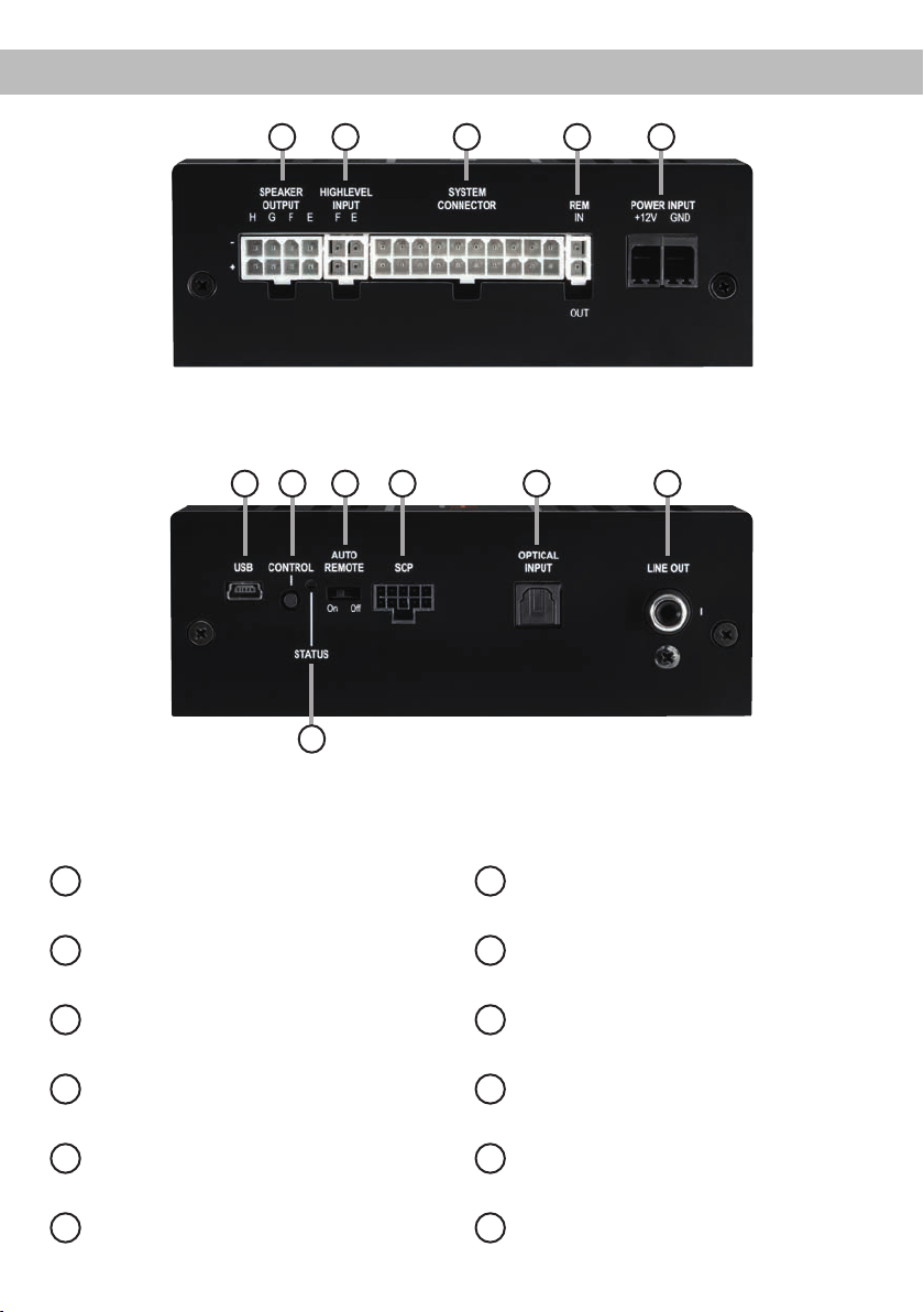
Anschluss- und Bedienelemente
1 2 3 4 5
7 8 9 10 11
6
12
Lautsprecherausgänge E - H
1
Seite 7, Punkt 3
Highlevel-Lautsprechereingäge E & F
2
Seite 7, Punkt 2
System Connector Eingang
3
Seite 7, Punkt 1
Remote-Anschlüsse
4
Seite 8, Punkt 6
Anschluss Stromversorgung
5
Seite 9, Punkt 7
USB Eingang
6
Seite 9, Punkt 8
4
Control Taster
7
Seite 11, Punkt 2
Auto Remote-Schalter
8
Seite 8, Punkt 5
SCP (Smart Control Port)
9
Seite 11, Punkt 3
Optischer Digitaleingang
10
Seite 8, Punkt 4
Vorverstärkerausgang
11
Seite 11, Punkt 12
Status LED
12
Seite 11, Punkt 1
Page 5
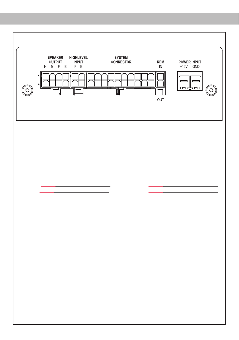
Hardware-Konguration
Abb. 1: Pinbelegung UP 8DSP
28272625
2221 10987654321
System Connector
1. Highlevel-Lautsprechereingang hinten links (-) / C
2. Highlevel-Lautsprechereingang vorne links (-) / A
3. Highlevel-Lautsprechereingang vorne rechts (-) / B
4. Highlevel-Lautsprechereingang hinten rechts (-) / D
5. Lautsprecherausgang hinten rechts (-) / D
6. Lautsprecherausgang hinten links (-) / C
7. Lautsprecherausgang vorne rechts (-) / B
8. Lautsprecherausgang vorne links (-) / A
9. Masse* / Wichtig: Pin darf nicht belegt werden!
10. Masse*/ Wichtig: Pin darf nicht belegt werden!
de
2019181716151413121132313029 2423
11. Highlevel-Lautsprechereingang hinten links (+) / C
12. Highlevel-Lautsprechereingang vorne links (+) / A
13. Highlevel-Lautsprechereingang vorne rechts (+) / B
14. Highlevel-Lautsprechereingang hinten rechts (+) / D
15. Lautsprecherausgang hinten rechts (+) / D
16. Lautsprecherausgang hinten links (+) / C
17. Lautsprecherausgang vorne rechts (+) / B
18. Lautsprecherausgang vorne links (+) / A
19. +12 Volt* / Wichtig: Pin darf nicht belegt werden!
20. +12 Volt* / Wichtig: Pin darf nicht belegt werden!
Highlevel Input E - F
21. Highlevel-Lautsprechereingang Kanal F (-)
22. Highlevel-Lautsprechereingang Kanal E (-)
Speaker Output E - H
25. Subwooferausgang 2 (-) / H
26. Subwooferausgang 1 (-) / G
27. Lautsprecherausgang F (-)
28. Lautsprecherausgang E (-)
23. Highlevel-Lautsprechereingang Kanal F (+)
24. Highlevel-Lautsprechereingang Kanal E (+)
29. Subwooferausgang 2 (+) / H
30. Subwooferausgang 1 (+) / G
31. Lautsprecherausgang F (+)
32. Lautsprecherausgang E (+)
* Nicht belegt beim beiliegenden System Connector Anschlusskabel.
5
Page 6
Hardware-Konguration
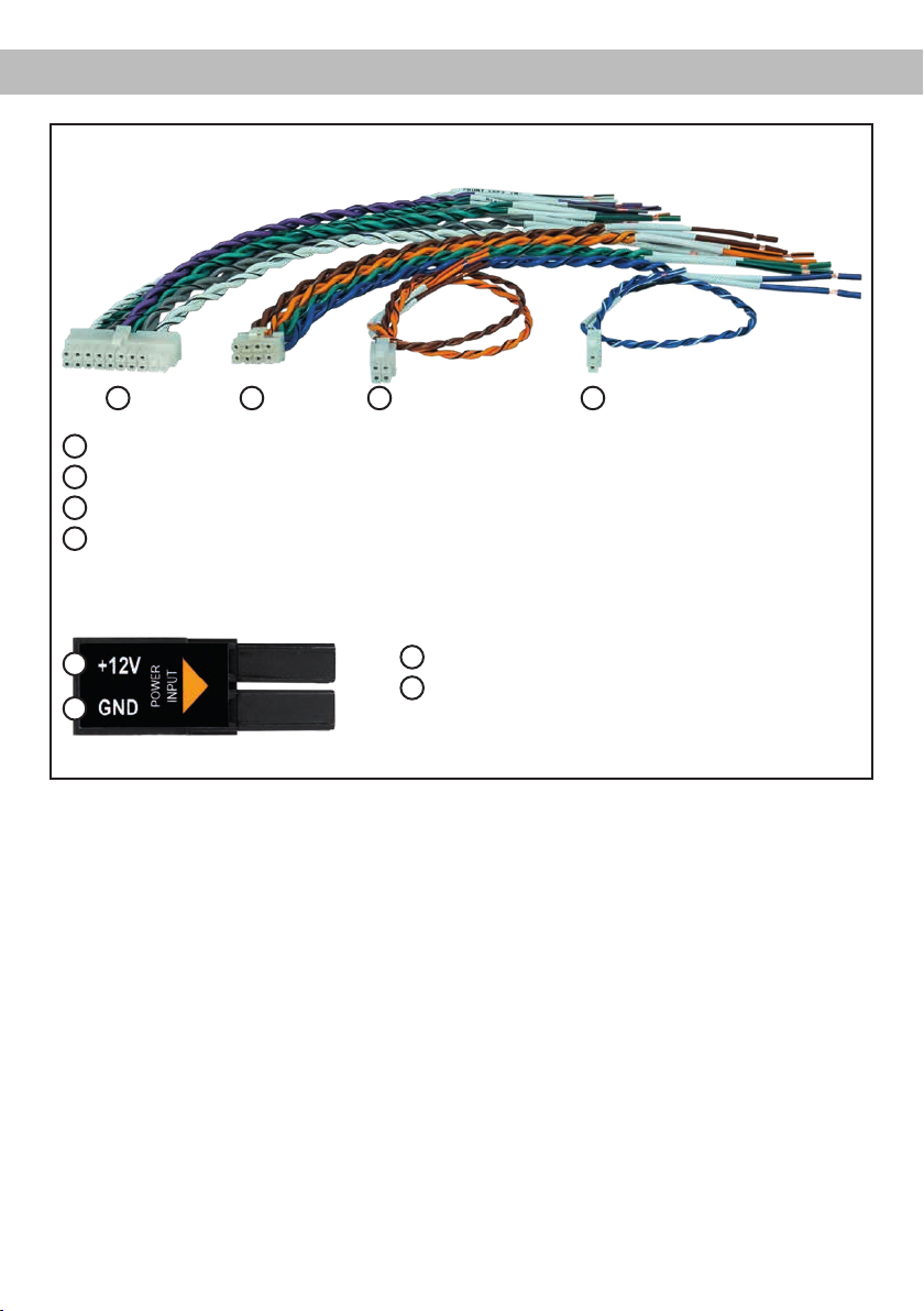
Abb. 2: Übersicht Anschlusskabel
1 2 3
1
System Connector Anschlusskabel
2
Speaker Output E - H Anschlusskabel
3
Highlevel Input E - F Anschlusskabel
4
Remote (REM IN / OUT) Anschlusskabel
Abb. 3: Belegung Power Input Stecker
A
B
Steckeroberseite
4
A
+12 V – Zum Anschluss des +12 V Versorgungskabels.
B
GND – Zum Anschluss des Massekabels.
6
Page 7

de
Kongurieren Sie den MATCH UP 8DSP in der
nachfolgenden Reihenfolge
Achtung: Für die Durchführung der nachfolgenden
Schritte werden Spezialwerkzeuge und Fachwissen
benötigt. Um Anschlussfehler und Beschädigungen
zu vermeiden, fragen Sie im Zweifelsfall Ihren Einbauspezialisten und beachten Sie zwingend die
allgemeinen Anschluss- und Einbauhinweise (siehe
Seite 2).
1. Anschluss des System Connector
1. Anschluss der Highlevel-Lautsprechereingänge A - D: Die Highlevel-Lautsprechereingänge (siehe Seite 5, Abb. 1, Nr. 1 - 4
und Nr. 11 - 14) können mit Hilfe des beiliegenden MATCH Anschlusskabels direkt mit
den Lautsprecherausgängen des Werksbzw. Nachrüstradios verbunden werden.
Dabei müssen nicht zwingend alle Eingänge
belegt werden. Es ist ausreichend, zwei der
vier Highlevel-Lautsprechereingänge zu belegen. Mit Hilfe der DSP PC-Tool Software
können die Eingangssignale auf die 9 Ausgangskanäle des Verstärkers individuell aufgeteilt werden.
Achten Sie bitte auf eine korrekte Polung!
Wenn Sie einen oder mehrere Anschlüsse
verpolen, kann dadurch die Funktion des
Verstärkers beeinträchtigt werden. Bei Verwendung dieses Eingangs muss der Remote-Eingang (REM IN) nicht belegt werden, da
sich der Verstärker automatisch einschaltet,
sobald ein Lautsprechersignal anliegt.
2. Anschluss der Lautsprecherausgänge A - D:
Die Lautsprecherausgänge (siehe Seite 5,
Abb. 1 Nr. 5 - 8 und Nr. 15 - 18) können mit
Hilfe des beiliegenden MATCH Anschlusskabels direkt mit den Lautsprecherleitungen
verbunden werden. Verbinden Sie niemals
die Lautsprecherleitungen mit der Kfz-Masse (Fahrzeugkarosserie). Dieses kann Ihren
Verstärker zerstören. Achten Sie darauf,
dass alle Lautsprechersysteme phasenrichtig angeschlossen sind, d.h. Plus zu Plus
und Minus zu Minus. Vertauschen von Plus
und Minus hat einen Totalverlust der Basswiedergabe zur Folge. Der Pluspol ist bei
den meisten Lautsprechern gekennzeichnet.
Die Impedanz pro Kanal darf 4 Ohm nicht
unterschreiten, da sonst die Schutzschaltung des Verstärkers aktiviert wird.
Achtung: Verwenden Sie zum Anschluss
ausschließlich das mitgelieferte System
Connector Anschlusskabel oder einen passenden Kabelbaum aus dem MATCH Zubehörprogramm.
2. Anschluss der Highlevel-Lautsprechereingänge E & F (optional)
Die Highlevel-Lautsprechereingänge E & F
können direkt mit den Lautsprecherausgängen
des Werks- bzw. Nachrüstradios mit Hilfe des
beiliegenden Anschlusskabels verbunden werden (siehe Seite 5, Abb. 1, Nr. 21 - 28). Achten
Sie bitte auf eine korrekte Polung! Wenn Sie
einen oder mehrere Anschlüsse verpolen, kann
dadurch die Funktion des Verstärkers beeinträchtigt werden. Bei Verwendung dieses Eingangs muss der Remote-Eingang (REM IN /
Seite 4, Punkt 4) nicht belegt werden, da sich
der Verstärker automatisch einschaltet, sobald
ein Lautsprechersignal anliegt.
Achtung: Verwenden Sie zum Anschluss ausschließlich das mitgelieferte Anschlusskabel mit
dem 4-poligen Stecker und den oenen Kabel-
enden (Seite 6, Abb. 2) oder einen passenden
Kabelbaum aus dem MATCH Zubehörprogramm.
3. Optional: Anschluss der Lautsprecherausgänge E - H
An die Lautsprecherausgänge können mit Hilfe des beiliegenden MATCH Anschlusskabels
Lautsprechersysteme sowie an die zwei Leistungs-Kanäle G & H Subwoofer angeschlossen
werden (siehe Seite 5, Abb. 1, Nr. 25 - 32).
Verbinden Sie die Lautsprecherleitungen niemals mit der Kfz-Masse (Fahrzeugkarosserie).
Dieses kann Ihren Verstärker zerstören. Achten Sie darauf, dass alle Lautsprechersysteme
phasenrichtig angeschlossen sind, d.h. Plus
zu Plus und Minus zu Minus. Vertauschen von
Plus und Minus hat einen Totalverlust der Basswiedergabe zur Folge. Der Pluspol ist bei den
meisten Lautsprechern gekennzeichnet. Die
Impedanz pro Kanal darf 4 Ohm für die Kanäle
E - F und 2 Ohm für die Kanäle G und H nicht
7
Page 8

Hardware-Konguration
unterschreiten, da sonst die Schutzschaltung
des Verstärkers aktiviert wird.
Achtung: Verwenden Sie zum Anschluss ausschließlich das mitgelieferte Anschlusskabel mit
dem 8-poligen Stecker und den oenen Kabel-
enden (Seite 6, Abb. 2) oder einen passenden
Kabelbaum aus dem MATCH Zubehörprogramm.
4. Anschluss einer digitalen Signalquelle im
SPDIF Format
Sofern Sie über eine Signalquelle mit optischem Digitalausgang verfügen, kann diese
an den Verstärker angeschlossen werden. Die
„Sampling Rate“ muss zwischen 12 - 96 kHz
liegen
. Das Eingangssignal wird automatisch
an die interne Abtastrate angepasst. Werkseitig ist die manuelle Einschaltung des Eingangs
über eine optionale Fernbedienung konguriert.
Möchten Sie den Eingang automatisch bei Anliegen eines Audiosignals aktivieren, können
Sie dies in der DSP PC-Tool Software unter
dem Menüpunkt Signalmanagement im DCM
kongurieren.
Die Einschaltautomatik des Verstärkers funktioniert bei Verwendung des Digitaleingangs nicht,
so dass der Remote-Eingang (REM IN / Seite 4, Punkt 4) zwingend belegt werden muss.
Wichtig: Das digitale Audiosignal einer Quelle ist üblicherweise nicht lautstärkegeregelt.
Das bedeutet, dass an den Signalausgängen
des MATCH UP 8DSP der volle Pegel anliegt
und die angeschlossenen Verstärker voll ausgesteuert werden. Dies kann im Extremfall
die Lautsprecher zerstören. Wir raten deshalb
dringend dazu, eine optionale Fernbedienung
zur Einstellung der Lautstärke der digitalen
Signaleingänge zu verwenden!
Hinweis: Der MATCH UP 8DSP kann nur unkomprimierte, digitale Stereo PCM-Signale mit
einer Abtastrate zwischen 12 kHz und 96 kHz
verarbeiten. Es können keine MP3- oder Dolbycodierten Daten verarbeitet werden, sondern
ausschließlich Stereosignale.
5. Konguration des Remote-Eingangs
Die Einschaltung der MATCH UP 8DSP erfolgt automatisch bei Ansteuerung über die
Highlevel-Lautsprechereingänge des System
8
Connectors und/oder Highlevel Inputs E & F
oder sobald ein Remote-Signal am RemoteEingang (REM IN) anliegt. Mit Hilfe des Auto
Remote Schalters (Seite 4, Punkt 8) kann die
automatische Einschaltung über die HighlevelLautsprechereingänge deaktiviert werden. Dies
sollte vorgenommen werden, wenn es beispielsweise zu Störgeräuschen beim Ein- und
Ausschalten des Verstärkers kommt.
On: Einschaltung über Highlevel-Lautspreche-
reingänge aktiviert (Werkseinstellung).
O: Einschaltung über Highlevel-Lautspreche-
reingänge deaktiviert.
Hinweis: Wird die automatische Einschaltung
des Verstärkers deaktiviert, muss der RemoteEingang belegt werden. Eine automatische
Einschaltung über den Highlevel-Lautsprechereingang ist dann nicht mehr möglich.
6. Anschluss der Remote-Leitungen
Schließen Sie die Remote-Leitungen ausschließlich über das mitgelieferte Anschlusska-
bel mit dem 2-poligen Stecker und den oenen
Kabel enden (Seite 6, Abb. 2) oder einen passenden Kabelbaum aus dem MATCH Zubehörprogramm.
REM IN: Der Remote-Eingang
schalten der UP 8DSP, sofern die am System
Connector oder Highlevel Input E & F angeschlossene Signalquelle die automatische
Einschaltung nicht aktiviert oder der Verstärker
bewusst nur über ein Remote-Signal ein- und
ausgeschaltet werden soll.
Dazu muss der Remote-Eingang des Verstärkers mit dem Remote-Ausgang des Radios /
der Head Unit verbunden werden. Somit wird
die UP 8DSP über das Radio ein- und ausgeschaltet. Es wird dringend davon abgeraten,
den Remote-Eingang des Verstärkers über das
Zündungsplus des Fahrzeugs zu steuern, um
Störgeräusche beim Ein- und Ausschalten zu
vermeiden.
Hinweis: Bei Verwendung einer der HighlevelEingänge A - F muss der Remote-Eingang nicht
belegt werden, sofern das angeschlossene Radio über BTL-Ausgangsstufen verfügt. Wie Sie
die automatische Einschaltung über die Highlevel-Lautsprechereingänge deaktivieren kön-
nen, ist auf Seite 8 unter Punkt 5 „Konguration
dient zum Ein-
Page 9

de
des Remote-Eingangs“ nachzulesen.
REM OUT: Der Remote-Ausgang dient zum prozessorgesteuerten Einschalten eines am Line
Out angeschlossenen Verstärkers. Verbinden
Sie dazu den Remote-Ausgang der UP 8DSP
mit dem Remote-Eingang des Verstärkers, um
diesen über den internen DSP störungsfrei einund auszuschalten.
Dieser Ausgang aktiviert sich automatisch, so
bald der Bootvorgang des DSP abgeschlossen
ist. Zudem wird dieser Ausgang bei aktiviertem
„Power Save Mode“ und bei BetriebssoftwareUpdates abgeschaltet.
Wichtig: Verwenden Sie niemals ein anderes
Signal als den Remote-Ausgang, um einen
angeschlossenen Verstärker einzuschalten!
7. Anschluss der Stromversorgung
Vor dem Anschluss des +12 V Versorgungskabels an das Bordnetz muss die Autobatterie abgeklemmt werden.
Schließen Sie die Stromversorgung ausschließlich über den mitgelieferten Power Input
Stecker (siehe Seite 6, Abb. 3) an. Achten Sie
unbedingt auf eine korrekte Polarität.
+12 V: Das +12 V Stromkabel ist am Pluspol der
Batterie anzuschließen. Die Plusleitung sollte in
einem Abstand von max. 30 cm von der Batterie mit einer Hauptsicherung (50 A) abgesichert
werden. Verwenden Sie bei kurzen Leitungen
(< 1 m) einen Querschnitt von mindestens 6
mm². Bei längeren Leitungen empfehlen wir einen Querschnitt von 10 mm² bis 16 mm².
GND: Anschluss für die Masseleitung. Das
Massekabel muss an einer nicht isolierten Stelle mit dem Kfz-Chassis verbunden werden. Der
Kabelquerschnitt sollte den gleichen Durchmesser wie die Plusleitung haben. Ein nicht ausreichender Massekontakt führt zu unerwünschten
Störgeräuschen und Fehlfunktionen.
8. Anschluss an den Computer & Einschalten
Mit Hilfe des USB Eingangs kann die UP 8DSP
über das beiliegende Kabel mit dem Computer verbunden und anschließend über das
DSP PC-Tool konguriert werden.
Hinweis: Es können keine USB Speichermedien
an den Verstärker angeschlossen werden.
Bevor Sie die UP 8DSP das erste Mal an einen
Computer anschließen, gehen Sie auf unsere
Homepage und laden die aktuellste Software
Version des DSP PC-Tools herunter. Es ist
ratsam, regelmäßig nach Updates der Software
zu schauen, damit das Gerät immer auf dem
aktuellsten Stand ist.
Die Software sowie eine umfang-
reiche Knowledge Base nden Sie auf
www.audiotec-scher.com.
Es wird dringend empfohlen, die DSP PC-Tool
Knowledge Base vor der ersten Benutzung
durchzulesen, um Komplikationen und Fehler
zu vermeiden.
Wichtig: Stellen Sie sicher, dass der UP 8DSP
Verstärker bei der ersten Installation der Software noch nicht am PC angeschlossen ist. Verbinden Sie diesen erst, wenn die Software samt
der USB-Treiber vollständig installiert ist.
Im folgenden Abschnitt lesen Sie die wichtigsten Schritte zum Anschluss und der ersten
Inbetriebnahme:
1. Laden Sie die DSP PC-Tool Software unter
www.audiotec-scher.com herunter und
installieren diese auf ihrem Computer.
2. Schließen Sie danach den Verstärker mit
dem beiliegenden USB-Kabel an den Computer an. Wenn Sie längere Distanzen zu
überbrücken haben, verwenden Sie bitte
eine aktive USB-Verlängerung mit integriertem Repeater.
3. Schalten Sie erst die UP 8DSP ein und star-
ten Sie anschließend die Software. Sofern
die Betriebssoftware des Verstärkers nicht
mehr aktuell ist, wird diese automatisch aktualisiert.
9. Einstellen der Eingangsempndlichkeit der
analogen Signaleingänge
ACHTUNG: Es ist zwingend notwendig, die
Eingangsempndlichkeit der UP 8DSP an
die Signalquelle anzupassen, um Schäden
am Verstärker zu vermeiden.
Mit Hilfe der DSP PC-Tool Software kann die
Eingangsempndlichkeit optimal an die Signalquelle angepasst werden.
Die Eingangsempndlichkeit ist für alle Kanäle
ab Werk auf 11 Volt eingestellt. Dies ist in nahezu allen Fällen bereits die optimale Einstellung.
9
Page 10
Hardware-Konguration
Nur wenn die Signalquelle einen zu kleinen
Max imalpegel liefert, sollte die Eingangsemp-
ndlichkeit vorsichtig angehoben werden.
Hinweis: Muten Sie während dieser Prozedur
die Signalausgänge der UP 8DSP.
Zur Anpassung der Eingangsempndlichkeit
führen Sie bitte die folgenden Schritte durch:
1. Schalten Sie den Verstärker ein.
2. Starten Sie die DSP PC-Tool Software.
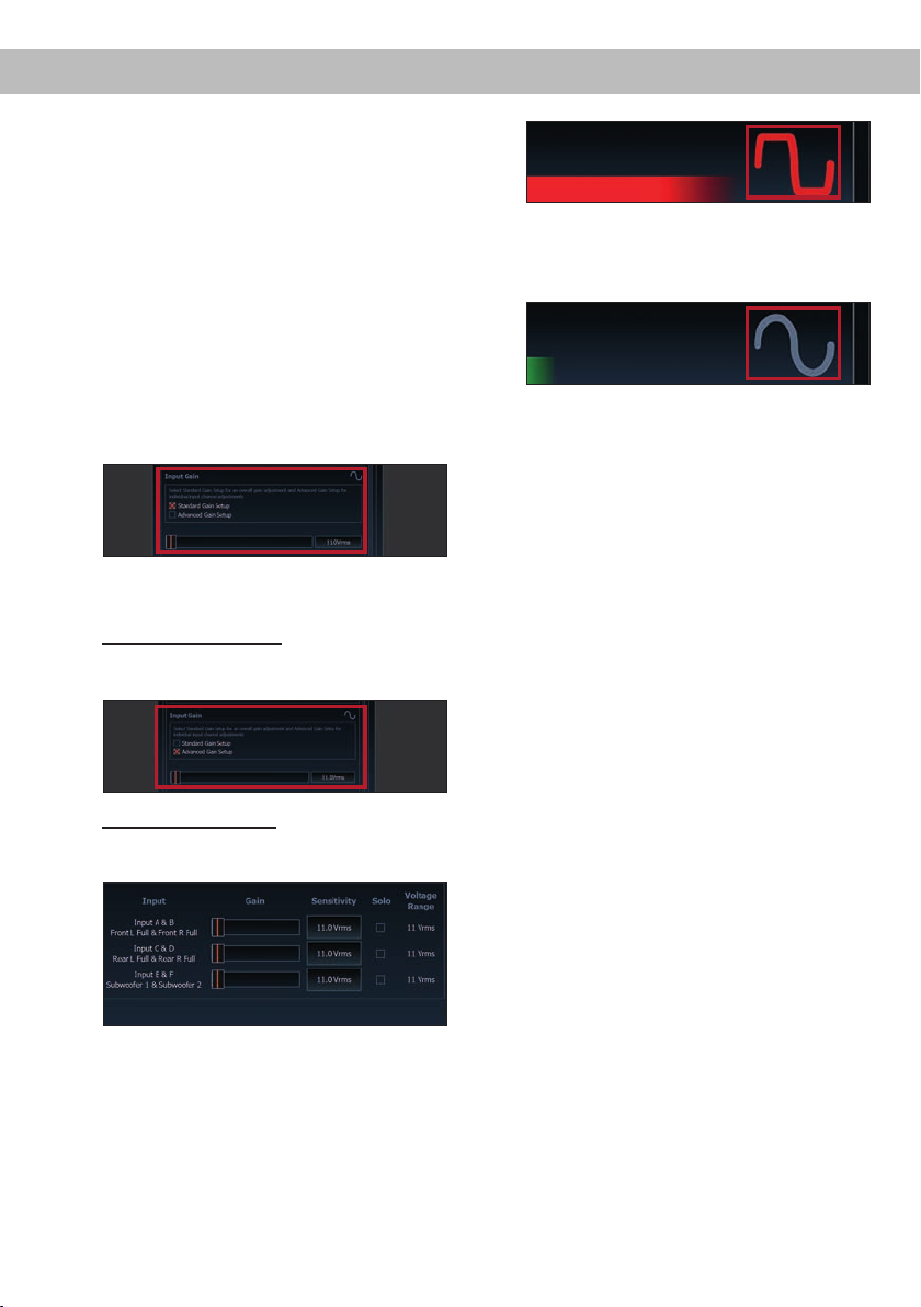
3. Die Einstellung der Eingangsempndlichkeit
nden Sie im Tab „ Signalverwaltung“ des
DCM-Menüs unter dem Punkt „Main Input →
Input Gain“.
4. Wählen Sie das Setupverfahren zur Einstel-
lung der Eingangsempndlichkeit aus.
Standard Gain Setup: Hier kann die Ein-
gangsempndlichkeit global für alle Kanäle
eingestellt werden.
Advanced Gain Setup: Bei diesem Verfahren
ist eine individuelle Einstellung für die einzelnen Kanalpaare möglich.
5. Drehen Sie die Lautstärke Ihres Radios auf
90 % der Gesamtlautstärke und spielen Sie
ein geeignetes Testsignal, z.B. Rosa Rauschen, (Vollaussteuerung 0 dB) ab.
6. Sollte die Clipping Anzeige im DSP PC-Tool
bereits leuchten (siehe Markierung im folgenden Bild), verringern Sie mit Hilfe des
Schiebereglers die Eingangsempndlichkeit,
bis die Clipping Anzeige erlischt.
10
7. Erhöhen Sie die Eingangsempndlichkeit bis
die Clipping Anzeige aueuchtet. Schieben
Sie nun den Regler zurück bis die Clipping
Anzeige wieder erlischt.
10. Konguration des internen DSPs
Es wird dringend empfohlen, vor der ersten Inbetriebnahme des Soundsystems die
grundlegenden Einstellungen im DSP mit
Hilfe der DSP PC-Tool Software vorzunehmen.
Nun können Sie den Verstärker mithilfe der
DSP PC-Tool Software frei kongurieren. Nützliche Hinweise zur korrekten Einstellung entnehmen Sie unserer Knowledge Base, welche
auf unserer Webseite bereit steht.
Achtung: Es wird dringend empfohlen, die
Lautstärke am Radio auf Minimum zu drehen
und die Signalausgänge zu muten. Speziell bei
Verwendung in vollaktiven Systemen besteht
sonst Zerstörungsgefahr für die Lautsprecher.
11. Eingangssignal analysieren
Prüfen Sie nun mit Hilfe des Input Signal
Analyzers (ISA) der DSP PC-Tool Software
das Eingangssignal auf werkseitig eingestelltes Equalizing und Allpass-Filter. Informationen zum ISA nden Sie in der umfangreichen Knowledge Base unserer Webseite
www.audiotec-scher.com.
Achtung: Es wird dringend empfohlen, vor der
ersten Inbetriebnahme die Lautstärke an der
Signalquelle auf Minimum zu drehen und an
die Vorverstärkerausgang der UP 8DSP noch
nichts anzuschließen, bis die grundlegenden
Einstellungen im Verstärker vorgenommen
wurden. Speziell bei Verwendung in vollaktiven
Systemen besteht sonst Zerstörungsgefahr für
die Lautsprecher.
Page 11

de
12. Optional: Anschluss des Vorverstärkerausgangs
Der Line Out ist ein Mono-Vorverstärker-Signal-
ausgang zum Anschluss eines zusätzlichen
Verstärkers. Diesen können Sie nun mit einem
entsprechenden Kabel (RCA / Cinch-Kabel) mit
dem Vorverstärker- / Lowlevel- / Cinch-Eingang
des nachgeschalteten Verstärkers verbinden.
Der Ausgang liefert eine maximale Ausgangsspannung von 3 Volt RMS. Bei Verwendung
dieses Ausgangs, ist es zwingend erforderlich,
Weitere Funktionen
1. Status LED
Die Status LED zeigt den Betriebszustand des
Verstärkers und dessen Speichers an.
Grün: Verstärker eingeschaltet und betriebsbereit.
Orange: Power Save Modus aktiv.
Rot: Protection Mode aktiv. Dieser kann unter-
schiedliche Ursachen haben. Der Verstärker ist
mit Schutzschaltungen gegen Über- und Unterspannung sowie Überhitzung ausgestattet.
Prüfen Sie in diesem Fall alle Anschlüsse auf
Fehler, wie z.B. Kurzschlüsse oder fehlerhafte
Verbindungen. Ist die Sicherheitsschaltung
der Temperaturüberwachung aktiv, wird der
Remote-Ausgang sowie die Signalausgabe abgeschaltet, bis ein sicherer Betrieb wieder gewährleistet werden kann.
Rot / grün langsam blinkend: Keine Betriebs-
software auf dem DSP installiert. Verbinden
Sie den Signalprozessor mit der DSP PC-Tool
Software und bestätigen Sie das automatische
Update der Betriebssoftware. Die aktuellste
Version des DSP PC-Tools nden Sie auf
www.audiotec-scher.com.
Rot / grün schnell blinkend: Aktuell ausgewähl-
ter Sound Setup-Speicherplatz ist leer. Ein
neues DSP Setup muss über die DSP PC-Tool
Software eingespielt werden oder schalten
Sie auf einen Speicherplatz mit vorhandenem
Sound Setup um.
2. Control Taster
Die UP 8DSP bietet 10 interne Speicherplätze
für Sound Setups. Mit Hilfe des Control Ta-
sters lässt sich zwischen zwei Speicherplätzen
den Remote-Ausgang (REM OUT) zum Einschalten des angeschlossenen Verstärkers zu
verwenden, da ansonsten Störgeräusche auftreten können.
13. Sound Tuning
Nun können Sie Ihr Sound Setup erstellen. In-
formationen rund um das Sound Tuning nden
Sie in unserer umfangreichen Knowledge Base
auf audiotec-scher.com oder kontaktieren
Sie Ihren MATCH Fachhändler vor Ort.
umschalten. Diese können im DSP PC-Tool
festgelegt werden. Zudem kann durch langes
Drücken des Tasters ein Geräte-Reset durchgeführt werden.
1. Setup-Wechsel: Taster 1 Sek. drücken.
Werkseitig sind die Speicherbereiche eins und
zwei eingestellt. Der Umschaltvorgang wird
durch einmaliges rotes Blinken der Status LED
angezeigt. Alternativ kann zur Umschaltung
die optionale Fernbedienung URC.3 verwendet werden. Um zwischen allen internen Speicherplätzen umschalten zu können, ist optionales Zubehör, wie z.B. die Fernbedienungen
DIRECTOR und CONDUCTOR notwendig.
2. Geräte-Reset: Taster länger als 5 Sek. gedrückt halten. Durch ein Geräte-Reset wird
der interne Speicher auf die Werkseinstellung
zurückgesetzt! Dies wird durch ein durchgehendes rotes Leuchten und grünes schnelles
Dauerblinken der Status LED angezeigt.
Achtung: Nach dem Resetten des Gerätes
kann die UP 8DSP keine Audiosignale mehr
wiedergeben, bis das Gerät mit Hilfe des DSP
PC-Tools geupdated wurde.
3. SCP (Smart Control Port)
Dieser Multifunktionseingang dient zum Anschluss von MATCH Zubehörprodukten, wie
beispielsweise einer Fernbedienung, mit deren
Hilfe diverse Funktionen des Verstärkers gesteuert werden können.
Die Funktionalität muss je nach Typ der Fern-
bedienung zuerst im „Device Conguration
Menu“ der DSP PC-Tool Software oder an der
11
Page 12
Weitere Funktionen
Fernbedienung selbst konguriert werden.
Achtung: Sofern das Zubehörprodukt keinen
NanoFit Stecker besitzt, verwenden Sie zum
Anschluss ausschließlich den mitgelieferten
NanoFit Adapter.
NanoFit Adapter
Kongurationsbeispiele
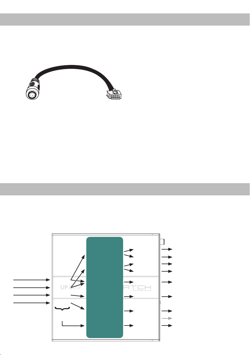
Beispiel 1: Kanalrouting mit Virtual Channel Processing
4-Kanal Headunit > Vorne: 2-Wege vollaktiv; Hinten: 2-Wege passiv + 2-Wege passiv Center + Line Out
für externen Subwoofer
Vom Autoradio Eingänge Ausgänge Zu den LautsprechernVirtuelle Kanäle
Front L High – Hochtöner VL
Front L Mid – Tiefmitteltöner VL
Front R High – Hochtöner VR
Front R Mid – Tiefmitteltöner VR
Front Center Full – 2-Wege passiv
Rear L Full – 2-Wege passiv HL
Rear R Full – 2-Wege passiv HR
Not assigned
Subwoofer 1 – Subwoofer
Front L Full
Front R Full
Rear L Full
Rear R Full
Input A
Input B
Input C
Input D
Summen-
signal A bis D
Front L Full (A)
Front R Full (B)
Front Center Full (E)
Rear L Full (C)
Rear R Full (D)
Subwoofer 1 (K)
SFX -
Augmented Bass
Processing
Amp Out A
Amp Out C
Amp Out B
Amp Out D
Amp Out E
Amp Out F
Amp Out G
Amp Out H
Line Out I
12
Page 13
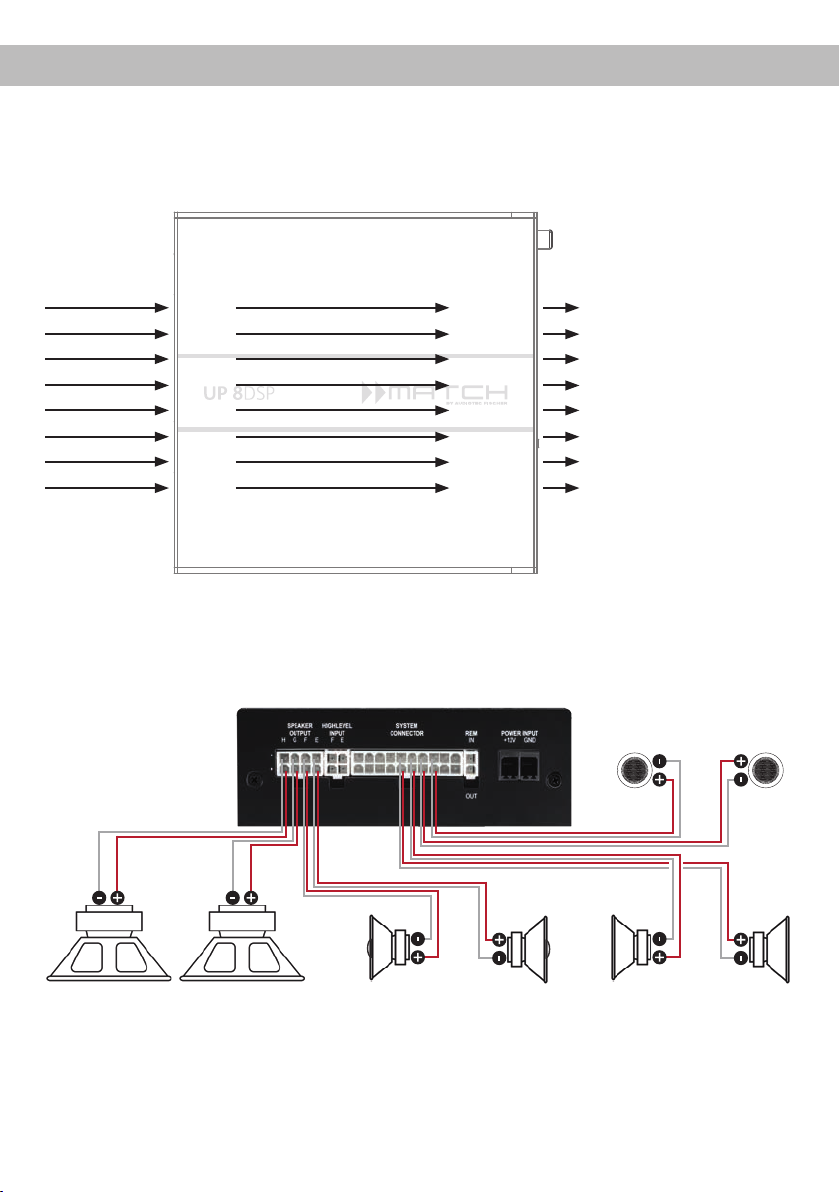
Beispiel 2: 8-Kanal 1 zu 1 Kanalrouting (IOR) z.B.: Vorne 2-Wege vollaktiv / Hinten 2-Wege passiv /
zwei Subwoofer mit einer Schwingspule (1 x 2 Ohm) – Nur in Verbindung mit dem optionalen MEC
ANALOG IN Modul
Vom Werksverstärker
Eingänge Ausgänge Zu den Lautsprechern
de
Front L High
Front R High
Front L Low
Front R Low
Rear L Full
Rear R Full
Subwoofer L
Subwoofer R
Input A
Input B
Input C
Input D
Input E
Input F
Input G*
Input H*
* Die hochbelastbaren Signaleingänge G & H des MEC ANALOG IN
Moduls werden auf die Subwoofer-Leistungskanäle G & H geroutet.
Amp Out A
Amp Out B
Amp Out C
Amp Out D
Amp Out E
Amp Out F
Amp Out G
Amp Out H
Front L High – Hochtöner VL
Front R High – Hochtöner VR
Front L Low – Tiefmitteltöner VL
Front R Low – Tiefmitteltöner VR
Rear L Full – 2-Wege passiv HL
Rear R Full – 2-Wege passiv HR
Subwoofer 1 – Subwoofer L
Subwoofer 2 – Subwoofer R
Hochtöner vorne
Links Rechts
Subwoofer L
Alternativ: Ein Subwoofer mit 2 x 2 Ohm
Doppelschwingspule
Links Rechts
Koaxiallautsprecher hinten
Links Rechts
Tiefmitteltöner vorneSubwoofer R
Ein Basic DSP-Setup nden Sie auf www.audiotec-scher.de unter Tools → Sound Setups.
Für weitere Anwendungsfälle kontaktieren Sie bitte Ihren MATCH-Fachhändler.
13
Page 14
Virtual Channel Processing (VCP)
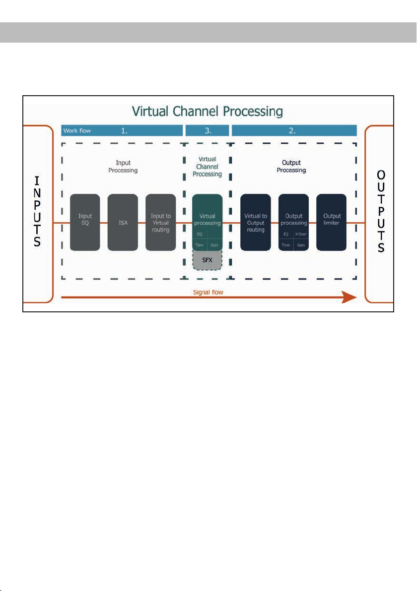
Die MATCH UP 8DSP bietet neben dem Standard Routing das Virtual Channel Processing (VCP), ein
mehrstuges Signalverarbeitungs-Konzept, welches die perfekte Konguration komplexer Soundsysteme
ermöglicht und somit ganz neue Möglichkeiten des Klangtunings erönet.
Das VCP erweitert den bisherigen Umfang des Gerätes um eine neue Ebene an prozessierten Kanälen,
welche sich zwischen den Ein- und Ausgängen bendet.
Insgesamt stehen acht zusätzliche prozessierte virtuelle Kanäle und neun prozessierte Ausgangskanäle
zur Verfügung.
Diese virtuelle Kanalebene bietet diverse Vorteile, gerade in komplexen Systemkongurationen.
Die Hauptvorteile dieses Konzeptes sind folgende:
- Ausgangskanalübergreifender Gruppen-Equalizer
- Mehrwege-Konguration der DSP-Soundeekte (SFX)
- Zusätzliche Funktionen wie Rear Attenuation
Weiterführende Informationen zum VCP und dessen Konguration nden Sie in unserer Knowledge Base
auf www.audiotec-scher.com.
14
Page 15
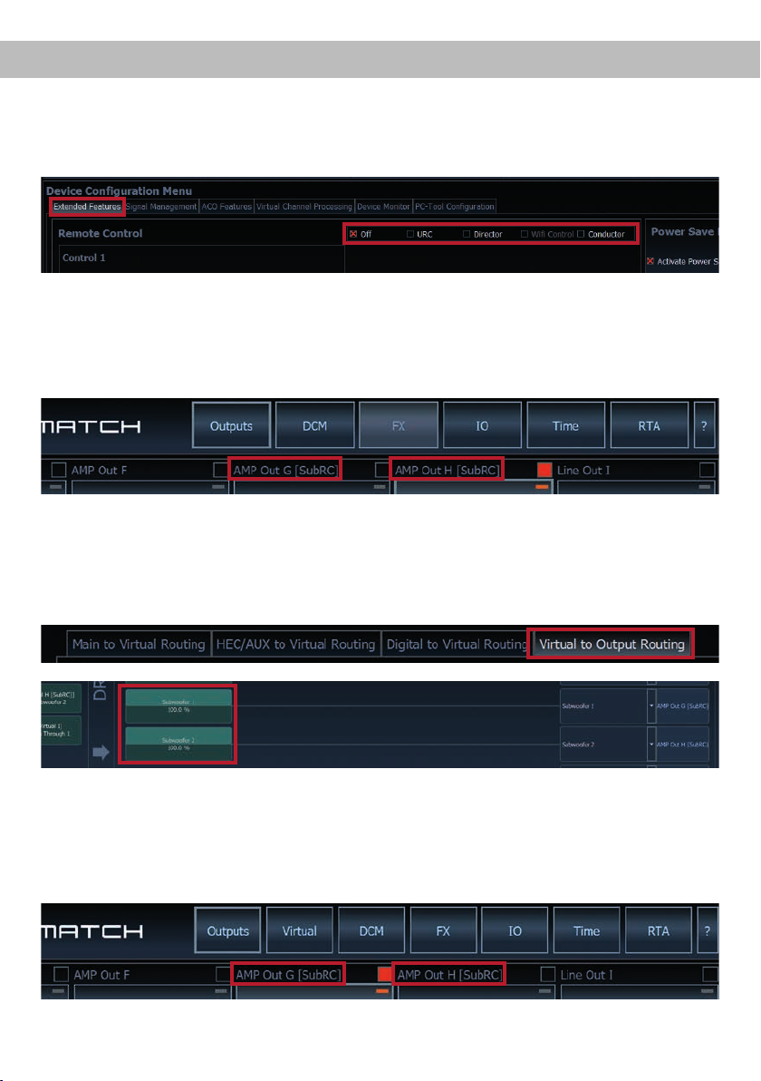
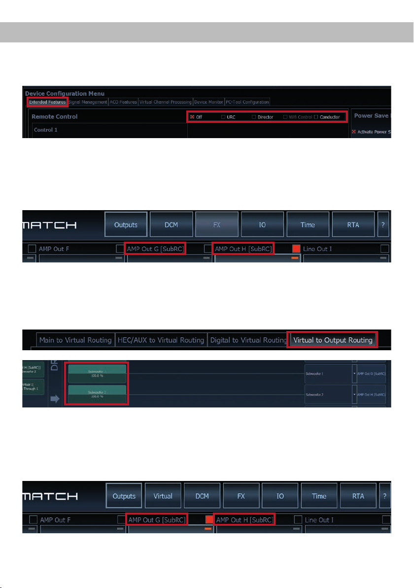
Zur Konguration einer Subwoofer-Fernbedienung müssen im DSP PC-Tool bestimmte Einstellungen vorgenommen werden.
Zunächst muss die entsprechende Fernbedienung im Tab „Erweiterte Einstellungen“ im DCM Menü der
DSP PC-Tool Software aktiviert und je nach Modell konguriert werden.
Bei nicht aktiviertem VCP ist die Subwoofer-Fernbedienung bei der UP 8DSP fest den Ausgangskanälen
G und H zugeordnet. In diesem Fall ist es nicht entscheidend, welcher Ausgang in der IO-Routingmatrix
mit „Subwoofer“ benannt wurde.
Im „Outputs“ Menü wird angezeigt, auf welche Ausgänge die SubRC (Subwoofer-Fernbedienung) wirkt:
Bei aktiviertem VCP hingegen wird die Subwoofer-Fernbedienung den Ausgangskanälen zugeordnet,
welche im „Virtual to Output Routing“ mit einem der beiden virtuellen Subwoofer-Signalen versorgt werden
(„Subwoofer 1“ oder „Subwoofer 2“). Dies kann jede beliebige Kombination an Ausgangskanälen sein.
deKonguration einer Subwoofer-FernbedienungKonguration einer Subwoofer-Fernbedienung
Im nachfolgenden Beispiel sind es die Ausgänge / Amp Outs G und H:
Hinweis: Bitte beachten Sie, dass den beiden virtuellen Subwoofer-Signalen „Subwoofer 1“ und / oder
„Subwoofer 2“ zuvor in den anderen Routing-Matrizen ein Eingangssignal zugewiesen werden muss.
Anschließend wird die Subwoofer-Regelung auch im „Outputs“ Menü hinter der Kanalbezeichnung als
[SubRC] angezeigt:
15
Page 16
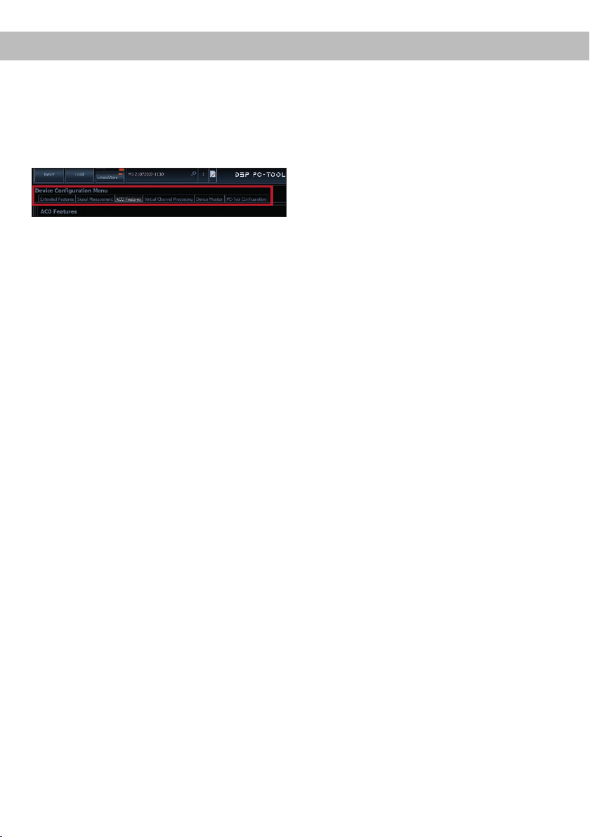
ACO Plattform-Features
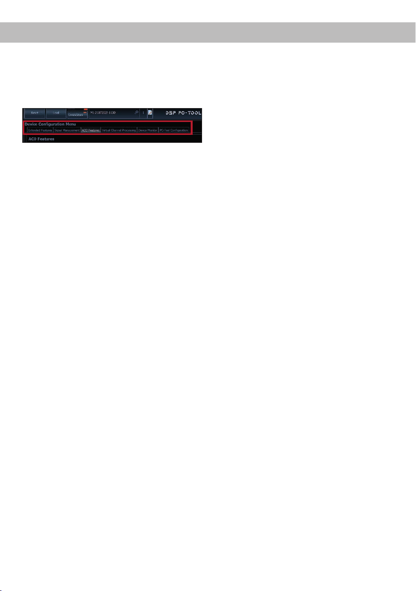
Neben den einzigartigen DSP-Sound eekten bietet die ACO-Plattform der UP 8DSP zusätzlich eine
Vielzahl an System-Features.
Im DCM Menü der DSP PC-Tool Software können
für einige dieser System-Features individuelle Einstellungen vorgenommen werden.
Turn On & O Delay
Hier kann die Verzögerungzeit, mit welcher der
Verstärker ein- und ausgeschaltet werden soll, festgelegt werden. Werkseitig sind 0,2 Sekunden eingestellt. Eine Änderung der Verzögerungszeit sollte
nur vorgenommen werden, wenn es beispielsweise
zu Störgeräuschen beim Ein- und Ausschalten des
Verstärkers kommt.
URC Setup Switch Conguration
Der ACO bietet Speicherplatz für zehn anstelle der
üblichen zwei Sound Setups.
Mit Hilfe einer optional erhältlichen URC Fernbedie
nung, oder des Control Tasters (siehe Seite 11) lässt
sich zwischen zwei der zehn Sound-Setup Spei
cherplätze umschalten. Diese zwei Speicherplätze
können in der „URC Setup Switch Conguration“
festgelegt werden. Werkseitig sind die Speicherbe
reiche eins und zwei ausgewählt. Um zwischen allen
internen Speicherplätzen umschalten zu können,
werden die optional erhältlichen Fernbedienungen
DIRECTOR und CONDUCTOR empfohlen.
-
-
-
Remote Output Conguration
An dieser Stelle kann festgelegt werden, ob der
Remote-Ausgang, der die angeschlossenen Endstufen ein- bzw. ausschaltet, während eines SoundSetup-Wechselvorgangs kurzzeitig deaktiviert werden soll. Standardmäßig ist dieses Feature aktiviert
(ON).
ADEP.3 Conguration
Bei Ansteuerung des Verstärkers über die Highlevel-Eingänge kann es in Verbindung mit manchen
Werksradios notwendig sein, den ADEP.3-Schaltkreis an den Diagnosemodus des Steuergeräts
anzupassen. Im Bereich „ADEP.3 SB compatibility
mode & Advanced Noise Suppression“ sollte eine
Anpassung vorgenommen werden, wenn es bspw.
zu Fehlfunktionen kommt (Stummschalten des Radios). Standardmäßig ist der Kompatibilitätsmodus
eingeschaltet (Enabled).
16
Page 17
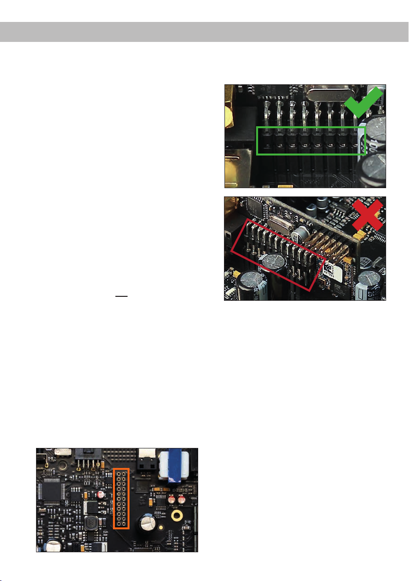
Einbau einer MATCH Extension Card
de
Der MATCH UP 8DSP Verstärker kann durch die
Montage einer MATCH Extension Card (MEC) um
weitere Schnittstellen wie beispielsweise einem
High Denition Bluetooth
einer High Resolution Audio USB Soundkarte etc.
erweitert werden.
Zur Montage einer MEC muss das Seitenblech der
UP 8DSP demontiert und gegen das der MEC beiliegende Seitenblech ausgetauscht werden.
Achtung: Installieren Sie ausschließlich für den
UP 8DSP Verstärker vorgesehene MEC Module
an der dafür vorgesehenen Position. Die Be-
nutzung eines nicht für das Gerät spezizierten
MEC Moduls oder eine Installation an einer nicht
dafür vorgesehenen Position im Gerät kann zu
Schäden am MEC Modul, dem Verstärker, des
Radios oder anderen angeschlossenen Geräten
führen.
Im folgenden Abschnitt nun die wichtigsten Schritte
zum Einbau und der ersten Inbetriebnahme eines
MEC Moduls:
1. Ziehen Sie zunächst alle Steckverbindungen
vom Gerät ab.
2. Lösen Sie die zwei Schrauben des Seitenblechs der Geräteseite mit dem USB Eingang
mit einem Kreuzschlitzschraubendreher und
entfernen dieses.
3. Ziehen Sie nun das Bodenblech zur Seite heraus.
4. Bereiten Sie das Modul für den Einbau in das
Gerät vor. Informationen dazu entnehmen Sie
bitte der Bedienungsanleitung des jeweiligen
MEC Moduls.
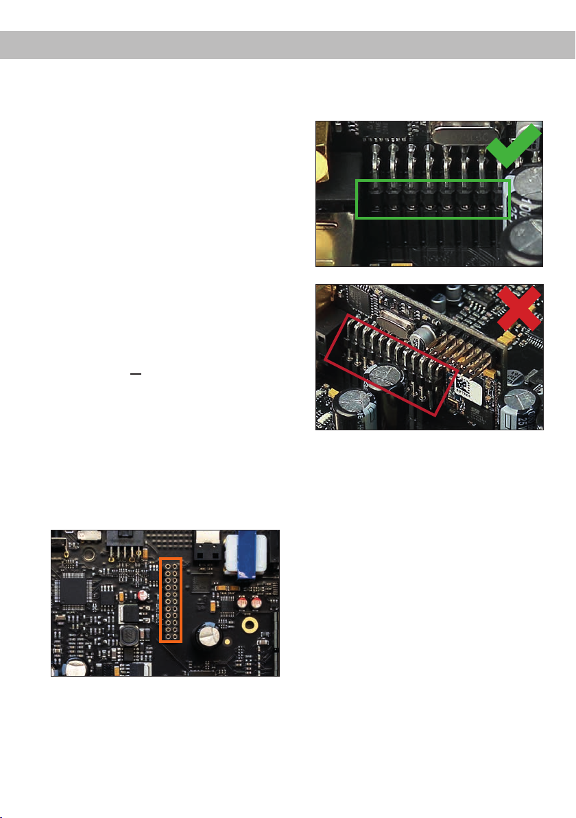
5. Stecken Sie das MEC Modul in den im Gerät
vorgesehenen Sockel (siehe Markierung im
nachfolgenden Bild).
®
Audio Streaming Modul,
6. Achten Sie auf den richtigen Sitz des MEC Moduls und darauf, dass alle Kontaktstifte vollständig im Sockel stecken.
7. Schieben Sie das Bodenblech wieder seitlich
in das Gehäuse des Verstärkers. Anschließend
befestigen Sie das neue, dem MEC Modul
beiliegende Seitenblech mit den Kreuzschlitzschrauben.
8. Verschrauben Sie das MEC Modul mit dem
Seitenblech. Genaue Informationen zur Befestigung entnehmen Sie bitte der Bedienungsanleitung des jeweiligen Moduls.
9. Schließen Sie alle Steckverbindungen wieder
an das Gerät an.
10. Schalten Sie den Verstärker ein. Das installierte
MEC Modul wird nun automatisch vom Gerät
erkannt und die Status LED des MEC Moduls
leuchtet grün.
11. Das Modul kann nun in der DSP PC-Tool Soft-
ware konguriert werden.
17
Page 18

Technische Daten
Leistung RMS
- Kanal A - F ...................................................................... 6 x 65 @ 4 Ohm
- Sub Out G - H................................................................. 2 x 90 Watt @ 4 Ohm
2 x 160 Watt @ 2 Ohm
Verstärkertechnologie .......................................................Class GD
Eingänge .......................................................................... 6 x Hochpegel-Lautsprechereingang
1 x Optisch SPDIF (12 - 96 kHz)
1 x Remote In
Eingangsempndlichkeit ................................................... Kanäle A - F: 2,8 - 11 Volt
Eingangsimpedanz ........................................................... 9 - 33 Ohm mit ADEP.3
Ausgänge ......................................................................... 8 x Lautsprecherausgang
1 x Cinch
1 x Remote Out
Ausgangsspannung Cinch................................................3 Volt RMS
Frequenzbereich...............................................................10 Hz - 22.000 Hz
DSP Auösung .................................................................64 Bit
DSP Rechenleistung ........................................................295 MHz (1,2 Mrd. MAC Operationen/Sek.)
Abtastrate ......................................................................... 48 kHz
DSP Typ ...........................................................................Audio Signalprozessor
Signalwandler ................................................................... A/D: BurrBrown
D/A: BurrBrown
Signal- / Rauschabstand (A-bewertet) ............................. Digitaleingang: 106 dB
Analogeingang: 104 dB
Klirrfaktor (THD) ...............................................................< 0,03 %
Dämpfungsfaktor .............................................................. > 100
Betriebsspannung.............................................................10,5 - 17 Volt (max. 5 Sek. bis hinab zu 6 Volt)
Leistungsaufnahme .......................................................... DC 12 V 40 A max.
Leerlaufstromaufnahme....................................................380 mA
Max. Remote-Ausgangsstrom .......................................... 500 mA
Sicherung .........................................................................2 x 25 A LP-Mini-Stecksicherung
Zusätzliche Features ........................................................ Class GD-Technologie mit dynamisch gere-
geltem Netzteil, 32 Bit CoProcessor, ADEP.3Schaltkreis, Start-Stop-Fähigkeit, Smart Control
Port, USB, MEC Slot, Auto Remote-Schalter,
galvanisch getrennter Line Out
Abmessungen (H x B x T) ................................................46 x 130 x 153 mm
Garantiehinweis
Die Garantieleistung entspricht der gesetzlichen
Regelung. Von der Garantieleistung ausgeschlossen sind Defekte und Schäden, die durch Überlastung oder unsachgemäße Behandlung entstanden
sind. Eine Rücksendung kann nur nach vorheriger
Absprache in der Originalverpackung, einer detaillierten Fehlerbeschreibung und einem gültigen
Kaufbeleg erfolgen.
Hinweis:
„Die Bluetooth® Wortmarke und die Logos sind eingetragene Warenzeichen der Bluetooth SIG, Inc. und jegliche Nutzung dieser Marken durch
die Audiotec Fischer GmbH geschieht unter Lizenz. Andere Handelsmarken und Handelsnamen gehören den jeweiligen Inhabern.“
18
Technische Änderungen, Druckfehler und Irrtümer
vorbehalten!
Für Schäden am Fahrzeug oder Gerätedefekte, hervorgerufen durch Bedienungsfehler des Gerätes,
können wir keine Haftung übernehmen. Dieses
Produkt ist mit einer CE-Kennzeichnung versehen.
Damit ist das Gerät für den Betrieb in Fahrzeugen
innerhalb der Europäischen Union (EU) zertiziert.
Page 19

Congratulations!
Dear Customer,
en
Congratulations on your purchase of this innovative
and high-qual ity MATCH product.
Thanks to more than 30 years of experience in
research and development of audio products this
amplier sets new standards in the range of digital
ampliers.
General instructions
General installation instructions for MATCH
components
To prevent damage to the unit and possible injury,
read this manual carefully and follow all installation
instructions. This product has been checked for
proper function prior to shipping and is guaranteed
against manufacturing defects.
Before starting your installation, disconnect the
battery’s negative terminal to prevent damage
to the unit, re and / or risk of injury. For a proper
performance and to ensure full warranty coverage,
we strongly recommend to get this product installed
by an authorized MATCH dealer.
Install your UP 8DSP in a dry location with sucient
air circulation for proper cooling of the equipment.
For safety reasons, the UP 8DSP must be professionally installed. Therefore, use the two mounting
plates which are included in delivery. These are at-
tached to the bottom of the amplier with two short
screws which are included in delivery, too.
When screwing the amplier to the vehicle chassis,
carefully examine the area around and behind the
proposed installation location to ensure that there
are no electrical cables or components, hydraulic
brake lines or any part of the fuel tank located behind the mounting surface. Failure to do so may result in unpredictable damage to these components
and possible costly repairs to the vehicle.
We wish you many hours of enjoyment with your
new MATCH UP 8DSP.
Yours,
AUDIOTEC FISCHER
General instruction for connecting the UP 8DSP
amplier
The UP 8DSP amplier may only be installed in motor vehicles which have a 12 Volts negative terminal
connected to the chassis ground. Any other system
could cause damage to the amplier and the electrical system of the vehicle.
The positive cable from the battery for the entire
sound system should be provided with a main fuse
at a distance of max. 30 cm from the battery. The
value of the fuse is calculated from the maximum
total current draw of the car audio system.
Use only the included MATCH cable or an optionally available MATCH cable harness for
connection of the UP 8DSP. The use of other
cables can result in damage of the ampli-
er, the head unit / car radio or the connected
loudspeakers! The fuses of the amplier may
only be replaced by identically rated fuses
(2 x 25 A) to avoid damage of the amplier.
Prior to installation, plan the wire routing to avoid
any possible damage to the wire harness. All
cabling should be protected against possible
crushing or pinching hazards. Also avoid routing
cables close to potential noise sources such as
electric motors, high power accessories and other
vehicle harnesses.
19
Page 20
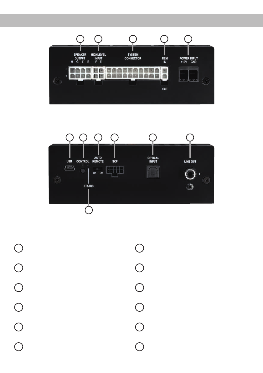
Connectors and control units
1 2 3 4 5
7 8 9 10 11
6
Speaker Output E - H
1
Page 23, point 3
Highlevel Input E & F
2
Page 23, point 2
System Connector input
3
Page 23, point 1
Remote connectors
4
Page 24, point 6
Power connector
5
Page 24, point 7
USB input
6
Page 25, point 8
20
12
Control pushbutton
7
Page 27, point 2
Auto Remote switch
8
Page 24, point 5
SCP (Smart Control Port)
9
Page 27, point 3
Optical Input
10
Page 23, point 4
Line Output
11
Page 26, point 12
Status LED
12
Page 27, point 1
Page 21
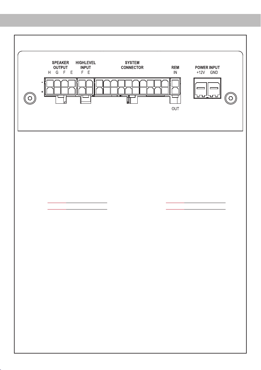
Fig. 1: Pin conguration UP 8DSP
28272625
2221 10987654321
System Connector
1. Highlevel loudspeaker input rear left (-) / C
2. Highlevel loudspeaker input front left (-) / A
3. Highlevel loudspeaker input front right (-) / B
4. Highlevel loudspeaker input rear right (-) / D
5. Loudspeaker output rear right (-) / D
6. Loudspeaker output rear left (-) / C
7. Loudspeaker output front right (-) / B
8. Loudspeaker output front left (-) / A
9. Ground* / Warning: Do not use this pin!
10. Ground* / Warning: Do not use this pin!
enHardware conguration
2019181716151413121132313029 2423
11. Highlevel loudspeaker input rear left (+) / C
12. Highlevel loudspeaker input front left (+) / A
13. Highlevel loudspeaker input front right (+) / B
14. Highlevel loudspeaker input rear right (+) / D
15. Loudspeaker output rear right (+) / D
16. Loudspeaker output rear left (+) / C
17. Loudspeaker output front right (+) / B
18. Loudspeaker output front left (+) / A
19. +12 Volts* / Warning: Do not use this pin!
20. +12 Volts* / Warning: Do not use this pin!
Highlevel Input E - F
21. Highlevel loudspeaker input channel F (-)
22. Highlevel loudspeaker input channel E (-)
Speaker Output E - H
25. Subwoofer output 2 (-) / H
26. Subwoofer output 1 (-) / G
27. Loudspeaker output F (-)
28. Loudspeaker output E (-)
23. Highlevel loudspeaker input channel F (+)
24. Highlevel loudspeaker input channel E (+)
29. Subwoofer output 2 (+) / H
30. Subwoofer output 1 (+) / G
31. Loudspeaker output F (+)
32. Loudspeaker output E (+)
* Not used on the enclosed System Connector connection cable.
21
Page 22
Hardware conguration
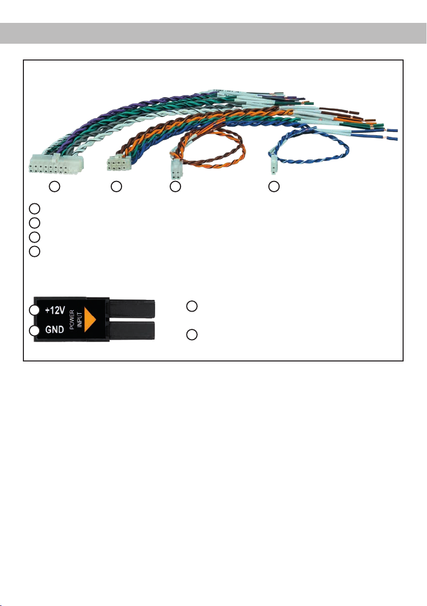
Fig. 2: Overview connection cables
1 2 3 4
1
System Connector connection cable
2
Speaker Output E - H connection cable
3
Highlevel Input E - F connection cable
4
Remote (REM IN / OUT) connection cable
Fig. 3: Pin assignment Power Input plug
A
+12 V – for connecting the UP 8DSP to the positive
A
B
Plug top side
B
GND – for connecting the ground cable.
terminal of the car´s battery.
22
Page 23

en
Congure the MATCH UP 8DSP as follows
Caution: Carrying out the following steps will require special tools and technical knowledge. In order to avoid connection mistakes and / or damage,
ask your dealer for assistance if you have any questions and follow all instructions in this manual (see
page 19). It is recommended that this unit will be
installed by an authorized MATCH dealer.
1. Connecting the System Connector
1. Connecting the highlevel speaker inputs A D: The highlevel loudspeaker inputs (see
page 21, g. 1, no. 1 - 4 and 11 - 14) can
be connected directly to the loudspeaker outputs of an OEM radio or aftermarket radio by
using the enclosed MATCH connection cable. It is not mandatory to use all highlevel
speaker inputs. It is sucient if two of four
highlevel loudspeaker inputs are connected.
With the DSP PC-Tool software it is possible to route the input signals to the 9 output
channels individually. Make sure that the polarity is correct. If one or more connections
have reversed polarity it may aect the performance of the amplier. If this input is used
the remote input (REM IN) does not need to
be connected as the amplier will automatically turn on once a loudspeaker signal is
received.
2. Connecting the loudspeaker outputs A - D:
The loudspeaker outputs (see page 21,
g. 1, no. 5 - 8 and 15 - 18) can be connected directly to the wires of the loudspeakers
by using the enclosed MATCH connection
cable.
Never connect any of the loudspeaker cables
to the chassis ground as this will damage
your amplier and your speakers. Ensure
that the loudspeakers are correctly connected (phase), i.e. plus to plus and minus to
minus. Exchanging plus and minus causes
a total loss of bass reproduction. The plus
pole is indicated on most speakers. The impedance per channel must not be lower than
4 Ohms, otherwise the amplier protection
will be activated.
Attention: Solely use the System Connector
connection cable which is included in deliv-
ery or an appropriate cable harness from the
MATCH accessories program for connection!
2. Connecting the highlevel speaker inputs E &
F (optionally)
The highlevel loudspeaker inputs E & F can be
connected directly to the loudspeaker outputs
of an OEM radio or aftermarket radio using
the enclosed MATCH connection cable (see
page 21, g. 1, no. 21 - 24). Make sure that the
polarity is correct. If one or more connections
have reversed polarity it may aect the performance of the amplier. If this input is used the
remote input (REM IN / page 20, point 4) does
not need to be connected as the amplier will
automatically turn on once a loudspeaker signal is received.
Attention: Solely use the connection cable with
the 4-pole connector and ying leads which is
included in delivery or an appropriate cable harness from the MATCH accessories program!
3. Optional: Connecting the speaker outputs
E - H
The loudspeaker outputs allow to connect
speaker systems using the included connection
cable as well as subwoofers to the two power
channels G & H (see page 21, g. 1, no. 25 -
32). Never connect any of the loudspeaker cables with the chassis ground as this will damage
your amplier and your speakers. Ensure that
the loudspeakers are correctly connected (in
phase), i.e. plus to plus and minus to minus. Exchanging plus and minus causes a total loss of
bass reproduction. The plus pole is indicated on
most speakers. The impedance of the speakers
must not be lower than 4 Ohms for channel E F and 2 Ohms for channel G and H, otherwise
the amplier protection will be activated.
Attention: Solely use the connection cable with
the 8-pole connector and ying leads (page 22,
g. 2) which is included in delivery for connect-
ing further loudspeakers or an appropriate cable
harness from the MATCH accessories program!
4. Connecting a digital signal source
If you have a signal source with an optical dig-
ital output you can connect it to the amplier
using the appropriate input. The sampling rate
23
Page 24

Hardware conguration
must be between 12 and 96 kHz. The input
signal is automatically adapted to the internal
sample rate.
In standard conguration the manual activation
via an optional remote control is congured.
Alternatively you can activate the automatic
turn-on feature in the DCM menu of the DSP
PC-Tool software.
The automatic turn-on circuit does not work
when the digital input is used. Therefore it is
mandatory to connect the remote input (REM
IN / page 20, point 4).
Important: The signal of a digital audio source
normally does not contain any information about
the volume level. Keep in mind that this will lead
to full level on the outputs of the UP 8DSP and
your connected ampliers.
This may cause severe damage to your speakers. We strongly recommend to use an optional
remote control for adjusting the volume level of
the digital signal inputs!
Note: The MATCH UP 8DSP can only handle
uncompressed digital stereo signals in PCM
format with a sample rate between 12 kHz and
96 kHz and no MP3- or Dolby-coded digital audio stream!
5. Conguration of the remote input
The UP 8DSP will be turned on automatically
if the highlevel inputs of the System Connector
and / or the Highlevel Inputs E & F are used or if
a signal is applied to the remote input terminal.
The Auto Remote switch (page 20, point 8) allows to deactivate the automatic turn-on feature
of the highlevel inputs. The feature should be
deactivated if there are e.g. noises while switch-
ing on / o the amplier.
On: Activation via highlevel speaker input is
enabled (by default).
O: Activation via highlevel speaker input is
disabled.
Note: If the automatic turn-on function is deactivated it is mandatory to use the remote input
terminal to power up the amplier!
6. Connecting the remote connectors
Only connect the remote wires using the 2-pole
connection cable with the ying leads which is
included in delivery (page 22, g. 2) or an ap-
24
propriate cable harness from the MATCH accessories program.
REM IN: The remote input has to be used to turn
on / o the amplier if the signal source which is
connected to the System Connector or Highlevel
Input E & F is not activating the “automatic turn-
on” function (Auto Remote) or if the amplier
shall only be activated / deactivated by a remote
signal applied to the remote input.
The remote wire should be connected to the
remote output / automatic antenna (aerial positive) output of the head unit / car radio. This is
only activated if the head unit is switched on.
Thus the amplier is switched on and o together with the head unit.
We do not recommend controlling the remote
input via the ignition switch to avoid pop noise
during turn on / o.
Note: This input does not need to be assigned
if one of the highlevel inputs A - F is used. To
deactivate the “automatic turn-on” function read
the description in point 5 “Conguration of the
remote input”.
REM OUT:
ing on / o an amplier that is connected to the
pre-amplier output (Line Out) of the MATCH
UP 8DSP. Therefore connect the remote output
of the UP 8DSP to the remote input of your am-
plier to switch it on and o via the internal DSP
without interfering signals. The remote output is
activated automatically as soon as the booting
process of the DSP is completed. Additionally
this output will be turned o during the “Power
Save Mode” or a software update process.
Important: Never use a dierent signal than
the remote output of the UP 8DSP to activate
a connected amplier!
7. Connection to power supply
Make sure to disconnect the battery before
installing the MATCH UP 8DSP!
Solely use the Power Input plug which is included in delivery for connection (see page 22,
g. 3). Make sure of correct polarity.
+12 V: Connect the +12 V power cable to the
positive terminal of the battery. The positive
wire from the battery to the amplier power terminals needs to have an inline fuse (50 A) at a
distance of less than 12 inches (30 cm) from
The remote output is used for turn-
Page 25
en
the battery. If your power wires are short (less
than 1 m / 40”) then a wire gauge of 6 mm² /
AWG 10 will be sucient. In all other cases we
strongly recommend gauges of 10 - 16 mm² /
AWG 8 – 6!
GND: Connector for the ground cable. The
ground wire must be connected to the vehicle
chassis at a non-insulated point. The cable
should have the same gauge as the +12 V wire.
Inadequate grounding causes audible interference and malfunctions.
8. Connecting the PC & rst start-up
The USB input enables the connection of the
UP 8DSP to a personal computer and its free
conguration with our DSP PC-Tool software
using the provided USB cable.
Please note: It is not possible to connect any
USB storage devices.
Prior to connecting the amplier to your PC visit
our website and download the latest version of
the DSP PC-Tool software.
We strongly recommend to carefully read the
DSP PC-Tool knowledge base before using the
software for the rst time in order to avoid any
complications and failures.
Important: Make sure that the amplier is not
connected to your computer before the software and USB driver are installed!
9. Adjustment of the input sensitivity of the analog inputs
ATTENTION: It is mandatory to properly
adapt the input sensitivity of the UP 8DSP to
the signal source in order to avoid damage
to the amplier.
The input sensitivity can be optimally adapted to
the signal source using the DSP PC-Tool software. Input sensitivity is factory set to 11 Volts.
This is denitely the best setting in most applications. Only if the head unit / car radio doesn t
deliver enough output level, the input sensitivity
should be increased.
Note: Mute all signal outputs of the UP 8DSP
during this setup.
For adjustment of the input sensitivity please
proceed as follows:
1. Turn on the amplier.
2. Start the DSP PC-Tool software.
3. The adjustment of the input sensitivity can
be found in the “Signal Management” tab of
the DCM menu under the item “Main Input →
Input Gain”.
In the following the most important steps how
to connect and the rst start-up are described:
1. Download the latest version of the DSP
PC-Tool software (available on our website
www.audiotec-scher.com) and install it
on your computer.
2. Connect the amplier to your computer using the USB cable that is included in delivery. If you have to bridge longer distances
please use an active USB extension cable
with integrated repeater.
3. First turn on the amplier and then start the
software. The operating software will be updated automatically to the latest version if it
is not up-to-date.
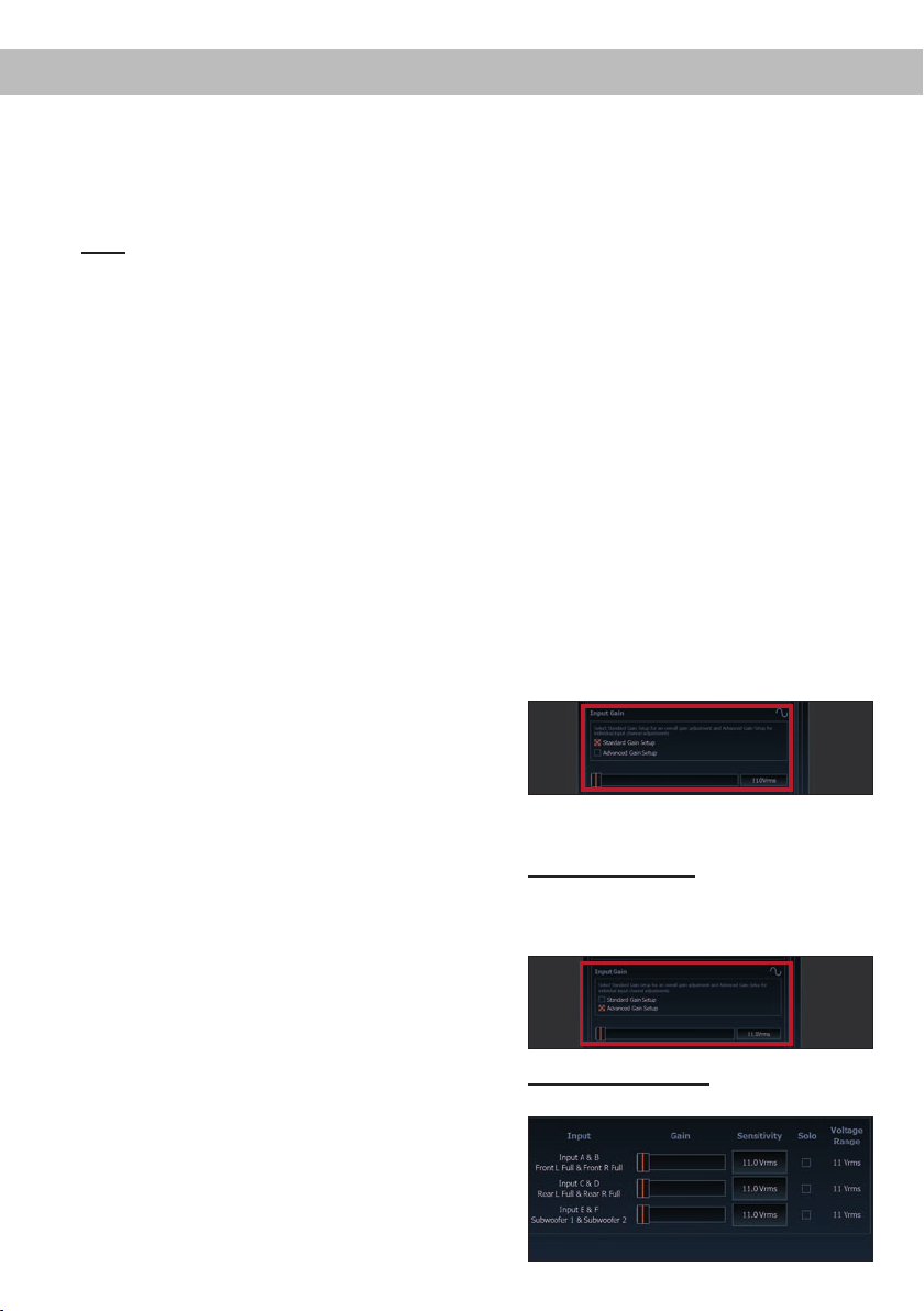
4. Select the setup method to adjust the input
sensitivity.
Standard Gain Setup: This method allows go
globally set the input sensitivity for all input
channels (only with “Low Voltage Range”
jumper plug-in position – see left).
Advanced Gain Setup: This method allows
an individual setting for each channel pair.
25
Page 26
Hardware conguration
5. Adjust the volume of your radio to approx.
90 % of the max. volume and playback an
appropriate test tone, e.g. pink noise (0 dB).
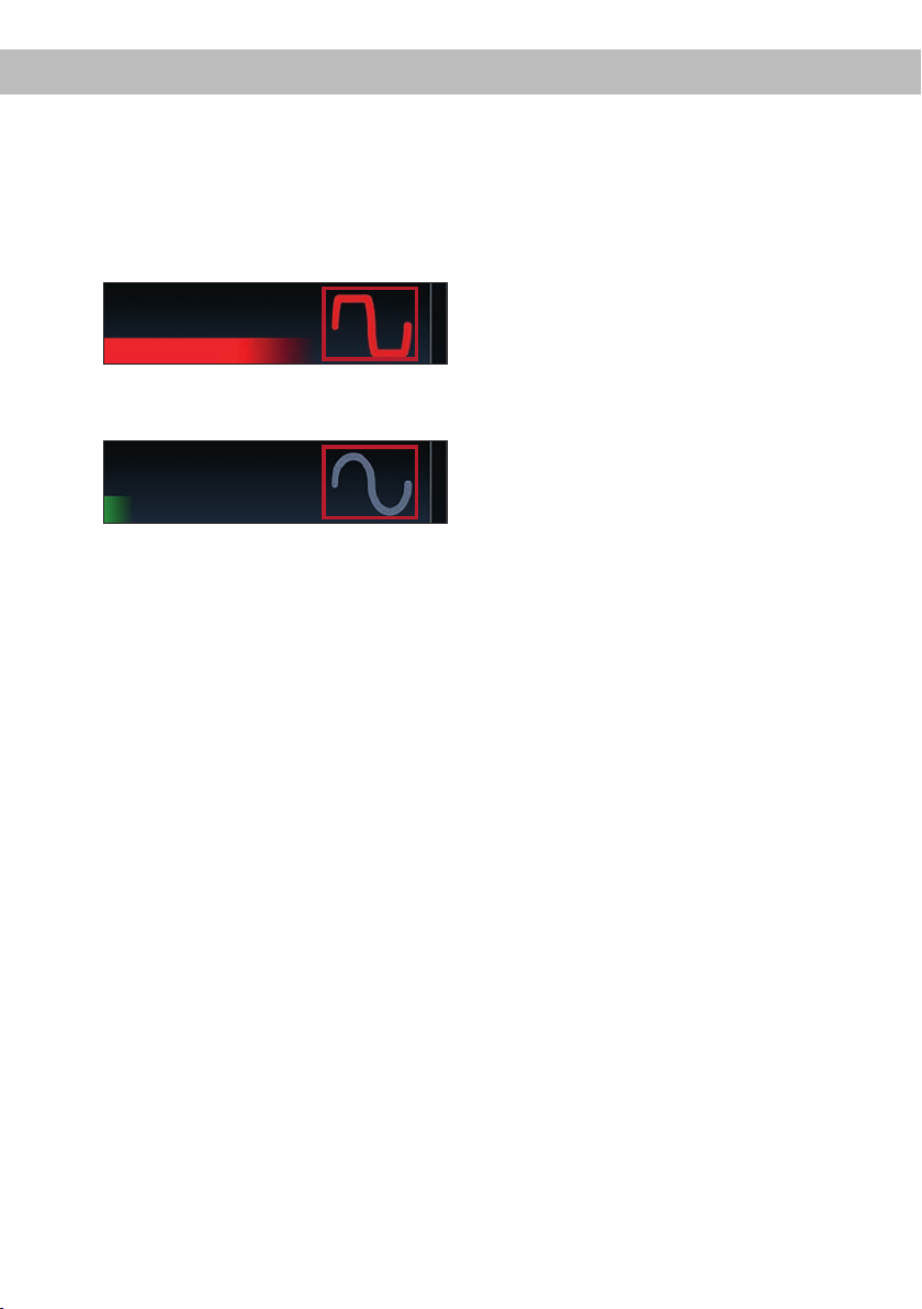
6. If the clipping indicator in the DSP PC-Tool
already lights up (see picture below), you
have to reduce the input sensitivity using the
scroll bar until the indicator turns o.
7. Increase the input sensitivity until the clipping indicator lights up. Now turn the control
back until the indicator turns o again.
10. Conguration of the internal DSP
The general amplier settings should be
conducted with the DSP PC-Tool software
before using the amplier for the rst time.
Now you are able to congure your UP 8DSP
with our intuitive DSP PC-Tool software. Useful
hints for the correct setting can be found in our
knowledge base at www.audiotec-scher.com.
Caution: We highly recommended to set the
volume of your car radio to minimum position
and to mute all signal outputs. Especially if the
UP 8DSP will be used in fully active applications, a wrong setup can destroy your speakers
right away.
11. Analyzing the input signal
Check the input signal for factory-set equal-
izing and all-pass lters using the Input
Signal Analyzer (ISA) of the DSP PC-Tool
software. Information about the ISA can be
found in the extensive Knowledge Base on
our website www.audiotec-scher.com.
Caution: We highly recommend to set the
volume of your car radio to minimum position
during rst start-up. Additionally no device
should be connected to the amplier until gen-
eral settings in the DSP PC-Tool software have
been made. Especially if the UP 8DSP will be
used in fully active applications, a wrong setup
can destroy your speakers right away.
12. Optional: Connecting the pre-amplier output
The Line Out is a mono oating-ground low level
output for connecting an additional power am-
plier. This output can now be connected to the
pre-amplier / lowlevel / RCA input of the external amplier using an appropriate cable (RCA /
Cinch cables).
The output provides a maximum output voltage
of 3 Volts RMS.
Please make sure that you always turn on / o
the external amplier using the remote output
(REM OUT) of the UP 8DSP in order to avoid
interfering noises.
26
Page 27
enAdditional functions
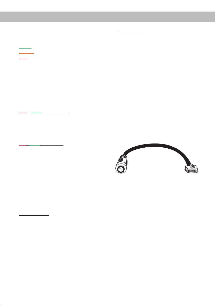
1. Status LED
The Status LED indicates the operating mode
of the amplier and of the DSP memory.
Green: Amplier is ready for operation.
Orange: Power Save Mode is activated.
Red: Protection Mode is active. This may have
dierent root causes. The amplier is equipped
with protection circuits against over- and undervoltage as well as overheating. Please check
for connecting failures such as short-circuits or
other wrong connections.
If the amplier is overheated the internal temperature protection switches o the remote and
signal output until it reaches a safe temperature
level again.
Red / green slow ashing: No operating soft-
ware installed. Connect the amplier to the DSP
PC-Tool software and conrm the automatic update of the operating system. You will nd the
latest version of the DSP PC-Tool software at
www.audiotec-scher.com.
Red / green fast ashing: The currently selected
sound setup memory is empty. A new setup has
to be loaded via the DSP PC-Tool software or
switch to a memory position with existing sound
setup.
2. Control pushbutton
The UP 8DSP provides 10 internal memory
locations for sound setups. The Control push-
button allows the user to switch between two
memory positions. These can be dened in the
DSP PC-Tool. In addition a device reset can be
made by pressing the button for a longer period.
1. Setup switch: Press Control pushbutton for
1 second. The memory locations one and two
are dened by default. Switching is indicated
by a single red ash of the Status LED. Alter-
natively, the optional URC.3 remote control can
be used for switching. To switch between all internal memory locations, optional accessories
like the DIRECTOR display remote control or
CONDUCTOR are required.
2. Device reset: Press pushbutton for ve sec-
onds. This completely erases the internal memory and is indicated by a continuous red glowing
and constant green ashing of the Status LED.
Attention: After erasing the setups from memory the UP 8DSP will not reproduce any audio
output until the device is updated via the DSP
PC-Tool software.
3. SCP (Smart Control Port)
This multi-functional input is designed for
MATCH UP 8DSP accessory products like a
remote control which allows to adjust several
features of the amplier. Depending on the type
of remote control, at rst its functionality has to
be dened in the “ Device Conguration Menu”
of the DSP PC-Tool software.
Attention: If the accessory product does
not have a NanoFit connector solely use the
NanoFit adaptor which is included in delivery
for connection.
NanoFit adaptor
27
Page 28
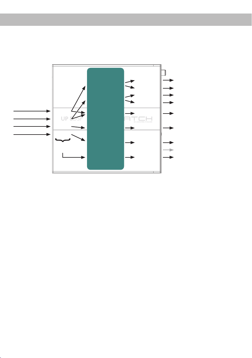
Conguration examples
Example 1: Channel routing with Virtual Channel Processing
4-channel head unit > Front: 2-way fully active; Rear: 2-way passive + 2-way passive center + Line Out
for external subwoofer
From car radio Inputs Outputs To speakersVirtual channels
Front L Full
Front R Full
Rear L Full
Rear R Full
Input A
Input B
Input C
Input D
Sum signal
A to D
Front L Full (A)
Front R Full (B)
Front Center Full (E)
Rear L Full (C)
Rear R Full (D)
Subwoofer 1 (K)
SFX -
Augmented Bass
Processing
Amp Out A
Amp Out C
Amp Out B
Amp Out D
Amp Out E
Amp Out F
Amp Out G
Amp Out H
Line Out I
Front L High – tweeter FL
Front L Mid – mid-woofer FL
Front R High – tweeter FR
Front R Mid – mid-woofer FR
Front Center Full – 2-way passive
Rear L Full – 2-way passive RL
Rear R Full – 2-way passive RR
Not assigned
Subwoofer 1 – Subwoofer
28
Page 29
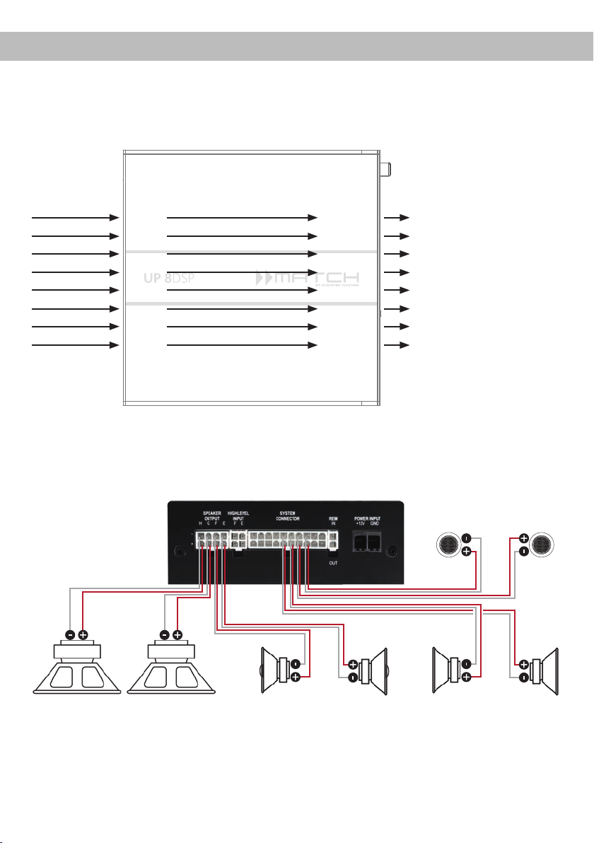
Example 2: 8-channel 1 to 1 channel routing (IOR) e.g.: Front 2-way fully active / Rear 2-way passive / two subwoofer with single voice coil (1 x 2 Ohms) – only in combination with the optional MEC
ANALOG IN module
From factory
amplier
Inputs Outputs To speakers
en
Front L High
Front R High
Front L Low
Front R Low
Rear L Full
Rear R Full
Subwoofer L
Subwoofer R
Input A
Input B
Input C
Input D
Input E
Input F
Input G*
Input H*
* The high power signal inputs G & H of the MEC ANALOG IN module
are routed to the high power subwoofer channels G & H.
Amp Out A
Amp Out B
Amp Out C
Amp Out D
Amp Out E
Amp Out F
Amp Out G
Amp Out H
.
Front L High – tweeter FL
Front R High – tweeter FR
Front L Low – mid-woofer FL
Front R Low – mid-woofer FR
Rear L Full – 2-way passive RL
Rear R Full – 2-way passive RR
Subwoofer 1 – Subwoofer L
Subwoofer 2 – Subwoofer R
Tweeter front
Left Right
Subwoofer L
Alternative: One subwoofer with 2 x 2 Ohms
dual voice coil
Left Right
Coaxial speakers rear
Left Right
Mid-woofer frontSubwoofer R
A basic DSP setup can be found at www.audiotec-scher.de under Tools → Sound Setups.
For further applications please contact your MATCH specialist dealer.
29
Page 30
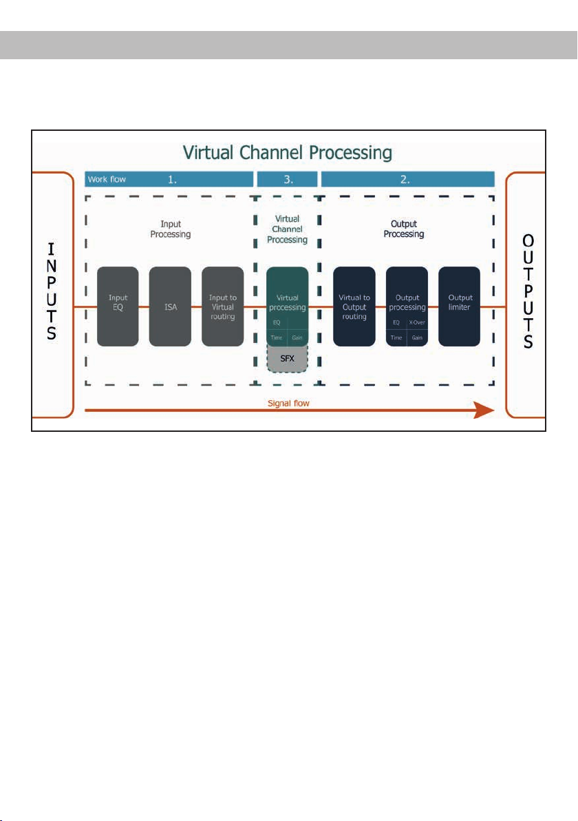
Virtual Channel Processing (VCP)
In addition to standard routing, the MATCH UP 8DSP oers Virtual Channel Processing (VCP), a multistage signal processing concept that enables the perfect conguration of complex sound systems,
opening up completely new possibilities for sound tuning.
The VCP extends the previous scope of the device by an additional layer of processed channels, which
is located between the inputs and outputs. A total of eight additional processed virtual channels and nine
processed output channels are available.
This virtual channel layer oers several advantages, especially in complex system congurations.
The main advantages of this concept are:
- Cross-channel group equalizers that aect several output channels simultaneously
- Multi-way speaker conguration of DSP sound eects (SFX)
- Additional features such as Rear Attenuation
For further information about the VCP and its conguration, please refer to our Knowledge Base at
www.audiotec-scher.com.
30
Page 31
Conguration of a subwoofer remote control
In order to congure a subwoofer remote control, specic settings have to be made in the DSP PC-Tool.
First, the appropriate remote control must be activated in the “Extended Features” tab in the DCM menu of
the DSP PC-Tool software and congured, depending on the model.
If the VCP is not activated, the subwoofer remote control of the UP 8DSP is permanently assigned to
the output channels G and H. In this case it does not matter which output is named “Subwoofer” in the IO
routing matrix.
In the “Outputs” menu you can also see to which outputs the SubRC (subwoofer remote control) is tied:
When VCP is activated, the subwoofer remote control is tied to the output channels that are supplied with
one of the two virtual subwoofer signals (“Subwoofer 1” or “Subwoofer 2”) in the “Virtual to Output Routing”
matrix. This can be any combination of output channels.
In the following example these are the amplier outputs G and H:
en
Note: Please note that an input signal must be assigned to the two virtual subwoofer signals “Subwoofer 1”
and / or “Subwoofer 2” in the other routing matrices.
Afterwards, the subwoofer control is also displayed in the “Outputs” menu next to the name of the channel
[SubRC]:
31
Page 32
ACO platform features
Beside the unique DSP sound eects the UP 8DSP
provides a bunch of new system features.
In the DCM menu of the DSP PC-Tool software individual settings can be made for several of these
system features.
Turn On & O Delay
This function allows to determine the delay time
with which the integrated DSP is switched on and
o. The factory setting is 0.2 seconds. The delay
time should only be modied if there are e.g. noises
while switching on / o the amplier.
URC Setup Switch Conguration
The ACO provides ten internal memory locations for
sound setups instead of the common two.
By using an optional URC remote control or the
Control pushbutton (see page 20) it is possible to
toggle between two of the ten memory locations.
These two memory locations can be determined in
the “URC Setup Switch Conguration”. The memory
locations one and two are preassigned by default.
To switch between all internal memory locations, the
optionally available remote controls DIRECTOR and
CONDUCTOR are recommended.
Remote Output Conguration
This function controls if the remote output (which
switches on and o the connected ampliers) will
be temporarily deactivated during a sound setup
switch. This function is activated (ON) by default.
ADEP.3 Conguration
If the UP 8DSP is connected to an OEM radio via
the highlevel inputs it may happen that the ADEP.3
circuit has to be adapted to the diagnostic mode of
the radio if the latter is equipped with a so-called
“class SB” output stage.
In the “ADEP.3 SB compatibility mode & Advanced
Noise Suppression” section, an adjustment should
be made if there are e.g. distortions occur in the
upper volume range.
The compatibility mode is enabled by default.
32
Page 33
enInstallation of a MATCH Extension Card
It is possible to extend the functionality of the
MATCH UP 8DSP by inserting an optional MATCH
Extension Card (MEC) – for example a High Denition Bluetooth
®
Audio Streaming module, a High
Resolution Audio USB soundcard etc.
To install a MATCH Extension Card it is necessary
to remove the side panel of the UP 8DSP and replace it by the new side panel that comes with the
MEC module.
Attention: Install the MEC module only in the
designated device and its specic slot. Using
the MEC module in other devices or slots can
result in damage of the MEC module, the ampli-
er, the head unit / car radio or other connected
devices!
Read in the following the steps how to install a MEC
module:
1. First disconnect all cables from the device.
2. Dismantle the side panel where the USB input
is located by removing the Phillips screws.
3. Pull out the bottom plate.
4. Prepare the module for installing it into the de-
vice. Any further mounting information will be
found in the instruction manual of the respective
MEC module.
5. Insert the MEC module into the specic slot of
the device which is marked in the following picture.
6. Make sure that the MEC module is installed
properly and all pins are fully inserted into the
socket.
7. Reinsert the bottom plate and x the new side
panel which is delivered with the MEC module
with the Phillips screws.
8. Bolt the MEC module to the side panel. Precise mounting information will be found in
the instruction manual of the respective MEC
module.
9. Reconnect all cables to the device.
10. Turn on the amplier. The MEC module is auto-
matically detected by the device and the Status
LED of the MEC module lights up green.
11. Now you are able to congure the MEC module
in the DSP PC-Tool software.
33
Page 34

Technical Data
Output power RMS
- Channel A - F..................................................................... 6 x 65 Watts @ 4 Ohms
- Sub Out G - H.................................................................... 2 x 90 Watts @ 4 Ohms
2 x 160 Watts @ 2 Ohms
Amplier technology ............................................................ Class GD
Inputs ................................................................................... 6 x Highlevel speaker input
1 x Optical SPDIF (12 - 96 kHz)
1 x Remote In
Input sensitivity .................................................................... Channels A - F: 2,8 - 11 Volts
Input impedance .................................................................. 9 - 33 Ohms with ADEP.3
Outputs ................................................................................ 8 x Speaker output
1 x RCA / Cinch
1 x Remote Out
Output voltage RCA / Cinch.................................................3 Volts RMS
Frequency response ............................................................ 10 Hz - 22,000 Hz
DSP resolution .....................................................................64 Bit
DSP power ..........................................................................295 MHz (2.4 billion MAC operations/sec.)
Sampling rate ...................................................................... 48 kHz
DSP type .............................................................................Audio signal processor
Signal converters ................................................................. A/D: BurrBrown
D/A: BurrBrown
Signal-to-noise ratio (A-weighted) ....................................... Digital input: 106 dB
Analog input: 104 dB
Distortion (THD) ................................................................... < 0.03 %
Damping factor .................................................................... > 100
Operating voltage ................................................................ 10.5 - 17 Volts (max. 5 sec. down to 6 Volts)
Power rating ........................................................................ DC 12 V
Current draw ........................................................................ 380 mA
Max. remote output current ................................................. 500 mA
Fuse..................................................................................... 2 x 25 A LP-Mini-fuse (APS)
Additional features ............................................................... Class GD technology with dynamically
controlled power supply, 32 Bit CoProcessor,
ADEP.3 circuit, Start-Stop capability, Smart
Control Port, USB, MEC slot, Auto Remote
switch, galvanically isolated Line Out
Dimensions (H x W x D) ...................................................... 46 x 130 x 153 mm / 1.81 x 5.12 x 6.02”
40 A max.
Warranty Disclaimer
The warranty service is based on the statutory regulations. Defects and damage caused by overload
or improper handling are excluded from the warranty service. Any return can only take place following
prior consultation, in the original packaging together
with a detailed description of the error and a valid
proof of purchase.
Note:
“The Bluetooth
Audiotec Fischer GmbH is under license. Other trademarks and trade names are those of their respective owners.”
®
word mark and logos are registered trademarks owned by Bluetooth SIG, Inc. and any use of such marks by
34
Technical modications, misprints and errors excepted! We accept no liability for damage to the
vehicle or device defects caused by the incorrect
operation of the device. This product has been issued a CE marking. This means that the device
is certied for use in vehicles within the European
Union (EU).
Page 35

en
Page 36

Audiotec Fischer GmbH
Hünegräben 26 · 57392 Schmallenberg · Germany
Tel.: +49 2972 9788 0 · Fax: +49 2972 9788 88
E-mail: match@audiotec-scher.com · Internet: www.audiotec-scher.com
 Loading...