

Page 1
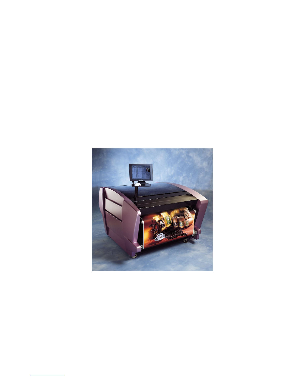
The SprinterB
User's Manual
Page 2
Copyright
© 2003 Matan Digital Printing Ltd.
All rights reserved.
No part of this publication may be reproduced, transmitted, transcribed,
stored in a retrieval system, or translated into any language or any
computer language, in any form or by any third party, without the prior
written permission Matan Digital Printers Ltd.,
Disclaimer
Matan Digital Printing Ltd., does not accept any responsibility for any
damage caused to its products by unauthorized personnel.
Environmental Policy
Clients are advised that when changing consumables or any
part of the printer, care should be taken to dispose of these
consumables or parts in the correct manner and according
to the laws and regulations of the local authorities.
For further details regarding the disposal of part and
consumables, contact your local distributor.
Head Office
Matan Digital Printers Ltd.,
11, Amal Street,
Rosh Ha'Ayin 48092
Israel
Tel: (972) 3 9039939 Fax: (972) 3 9039947
E-mail: [email protected]
Manual Version Number: Revision 0303
Software Version Number: 5.35
Declaration of Conformity
FCC
Page 3

Limited Warranty
For a period of 12 months from the date of original purchase (“Limited Warranty Period”)
(except for the Thermal Print Heads, which are guaranteed for 6 months), MATAN DIGITAL
PRINTERS (2001) LTD., (“Company”), will, at Company’s option, either replace or repair any
defective product manufactured by Company and sold by its authorized distributor,
(“Product”), in the (“Territory”) to the person making a claim under this Limited Warranty,
provided the original purchaser complies with the terms and conditions set forth herein
below.
This Limited Warranty applies only to a person or company that demonstrates to Company’s
reasonable satisfaction he or it was the original purchaser of a Product purchased in new
condition in the original package from an authorized distributor of Company in Territory.
This Limited Warranty is not transferable or assignable.
If a claim is made within Limited Warranty Period by the original purchaser. Company will
repair or replace a Product that, in Company’s reasonable judgment after inspection, is
defective in either workmanship or materials.
Company’s liability is limited to repair or replacement of a defective Product. Company will
not be responsible for any consequential or incidental damages or expenses of any kind or
nature, regardless of the cause, even if Company has any knowledge regarding the
probability of their occurrence. Without limiting the generality of this statement, Company
will not be liable for injury to persons or property, loss of use of the Product, lost goodwill,
lost profits, work stoppage, impairment of or damage to other goods. If any of the following
have occurred, it will void this Limited Warranty, and Company will have no liability of any
kind to original purchaser.
1. Product shows evidence it has been tampered with, or it has been subject to misuse,
abuse or negligent use, or,
2. Any repair or alteration of Product was made by someone other than Company, including
the distributor, except with Company’s written authorization, or,
3. Product was either improperly installed, operated or used for a purpose for which it was
not intended, or,
4. The original purchaser failed to provide normal maintenance, if any is required, in
accordance with Company’s instruction manual, or,
5. The serial numbers or other factory-installed labeling has been altered or removed.
The original purchaser should return the defective Product to Company at the address set
forth below, together with proof of purchase, packed with either the original packaging or
other similar packaging designed to avoid damage to Product during the course of shipment.
THIS LIMITED WARRANTY IS GIVEN IN LIEU OF ALL OTHER WARRANTIES WHETHER
EXPRESSED OR IMPLIED. THERE ARE NO WARRANTIES AS TO THE FITNESS OF
PRODUCT FOR ANY PARTICULAR PURPOSE. COMPANY DISCLAIMS ANY OTHER
WARRANTY, EXPRESS OR IMPLIED, THAT PRODUCT IS MERCHANTABLE.
HOWEVER, IF COMPANY IS HELD LIABLE, WHETHER DIRECTLY OR INDIRECTLY, FOR
ANY LOSS OR DAMAGE ARISING FROM UNDER THIS LIMITED WARRANTY OR
OTHERWISE, REGARDLESS OF CAUSE OR ORIGIN, COMPANY’S MAXIMUM LIABILITY
SHALL NOT EXCEED THE PURCHASE PRICE OF THE PRODUCT, WHICH SHALL BE
COMPLETE AND EXCLUSIVE REMEDY AGAINST COMPANY.
ALTERATIONS AND ADDITIONS TO OR IN CONNECTION WITH ANY PART, HARDWARE OR
SOFTWARE, OF THE SYSTEM MAY ONLY BE CARRIED OUT BY MATAN OR PURSUANT TO
ITS EXPLICIT AUTHORISATION, AND NO LIABILITY WHATSOEVER SHALL BE ACCEPTED
BY MATAN FOR ANY ALTERATIONS OR ADDITIOINS CARRIED OUT OTHERWISE, NOR
FOR ANY EFFECT SUCH ALTERATIONS OR PROVISIONS MAY HAVE ON THE SYSTEM OR
THE SUPPORT THEREOF.
No employee or representative of Company is authorized to change this warranty in any way
or grant any other warranty.
Page 4

Page 5

The SprinterB User's Manual i
Table of Contents
1 GETTING STARTED........................................................................................... 1-1
CONVENTIONS USED IN THIS MANUAL......................................................................................1-2
NOTATIONS IN THIS MANUAL ..................................................................................................1-2
IMPORTANT NOTES ...............................................................................................................1-3
2 OVERVIEW........................................................................................................ 2-1
THERMAL TRANSFER PRINTING TECHNOLOGY............................................................................2-1
DIRECT THERMAL PRINTING...................................................................................................2-1
THERMAL TRANSFER PRINTING ...............................................................................................2-1
YMCK ...............................................................................................................................2-1
3 GENERAL DESCRIPTION ................................................................................... 3-1
ABOUT THE SPRINTERB PRINTER ............................................................................................3-1
TECHNICAL DESCRIPTION ......................................................................................................3-2
THE POWER INLET CONNECTION..............................................................................................3-3
POWER SUPPLY UNITS............................................................................................................3-3
THE THERMAL PRINT HEAD (TPH)...........................................................................................3-4
TEMPERATURE CONTROL SYSTEM (LCS)...................................................................................3-4
THE RIBBON SYSTEM.............................................................................................................3-5
THE SUBSTRATE SYSTEM .......................................................................................................3-8
THE PULLING SYSTEM............................................................................................................3-9
THE SUBSTRATE PULLING CYLINDER AND PRESSING ARM ...........................................................3-9
THE SUBSTRATE COLLECTING SYSTEM...................................................................................3-10
THE PRESSURE ROLLERS PISTONS.........................................................................................3-10
THE PRESSURE ROLLERS SYSTEM .........................................................................................3-10
THE OPTIC SENSOR .............................................................................................................3-11
THE SCRAPER AND IONIZOR..................................................................................................3-12
THE SPRINTERB PC CONTROL STATION.................................................................................3-12
THE EMERGENCY STOP BUTTONS..........................................................................................3-13
THE SAFETY MICRO SWITCHES.............................................................................................3-13
Page 6

ii The SprinterB User's
M
4 SPECIFICATIONS...............................................................................................4-1
GENERAL............................................................................................................................4-1
ELECTRICAL SYSTEM ............................................................................................................4-2
ELECTRONIC SYSTEM ...........................................................................................................4-2
PC STATION........................................................................................................................4-2
AIR COMPRESSOR................................................................................................................4-3
TEMPERATURE CONTROL SYSTEM (TCS)..................................................................................4-3
PNEUMATICS .......................................................................................................................4-3
OPERATING CONDITIONS .......................................................................................................4-3
SUBSTRATE SPECIFICATIONS AND STORAGE..............................................................................4-4
INK ROLLER (RIBBON) SPECIFICATIONS AND STORAGE ...............................................................4-4
SHELF LIFE.......................................................................................................................... 4-4
5 INSTALLING THE SOFTWARE ............................................................................5-1
INSTALLING THE SOFTWARE ...................................................................................................5-1
6 AROUND THE WINDOWS....................................................................................6-1
ABOUT THE SPRINTERB MAIN SCREEN ....................................................................................6-1
THE MENU BAR...................................................................................................................6-1
THE TOOL BAR....................................................................................................................6-2
THE MAIN SCREEN INFORMATION CENTER ...............................................................................6-3
PRINT INFORMATION.............................................................................................................. 6-3
QUEUE STATISTICS............................................................................................................... 6-4
THE PRINTING INFORMATION CENTER ......................................................................................6-4
THE PRINTER QUEUE WINDOW ............................................................................................... 6-4
THE IMAGE MENU................................................................................................................6-5
THE IMPORT FILE DIALOG BOX ............................................................................................... 6-5
THE EDIT DIALOG BOX.......................................................................................................... 6-6
THE UTILITIES MENU..........................................................................................................6-11
THE CONFIGURATION DIALOG BOX........................................................................................ 6-11
THE CONTROL DIALOG BOX ................................................................................................. 6-13
THE PREFERENCES DIALOG BOX .......................................................................................... 6-15
Page 7

The SprinterB User's Manual iii
7 UPDATING THE SOFTWARE AND USER SERVICE CODE..................................... 7-1
THE USER PLUG ..................................................................................................................7-1
THE USER SERVICE CODE.....................................................................................................7-1
CREATING LOG FILES ...........................................................................................................7-2
VIEWING LOG FILES .............................................................................................................7-3
8 PREPARING YOUR PRINTER FOR PRINTING...................................................... 8-1
PRELIMINARY PREPARATIONS FOR PRINTING..............................................................................8-1
LOADING OR REPLACING A SUBSTRATE ROLL ............................................................................8-3
REPLACING THE USED RIBBONS ..............................................................................................8-8
OPERATING THE SUBSTRATE COLLECTING SYSTEM ..................................................................8-11
LOADING THE PRINTED SUBSTRATE INTO THE COLLECTING SYSTEM ...........................................8-12
UNLOADING THE PRINTED SUBSTRATE FROM THE COLLECTING SYSTEM ......................................8-12
SOFTWARE PREPARATIONS FOR PRINTING...............................................................................8-13
USING THE FORWARD ICON ..................................................................................................8-13
SETTING THE PRINT HEAD TEMPERATURES.............................................................................8-13
CONFIGURING THE SPRINTERB PRINTER .................................................................................8-14
SPECIFYING THE PRINT SETTINGS ..........................................................................................8-20
SETTING THE PIST ONS AND MOTORS PARAMETERS...................................................................8-24
SETTING THE PREFERENCES .................................................................................................8-28
SETTING THE ENCODER DIVISION ..........................................................................................8-29
MAIN MOTOR COEFFICIENT ..................................................................................................8-29
THE PRINTING PROCEDURE..................................................................................................8-30
IMPORTING A FILE TO THE PRINTING MENU..............................................................................8-30
DELETING A SELECTED FILE FROM THE IMPORT FILE DIALOG BOX .............................................8-32
RENAMING A FILE................................................................................................................8-32
DELETING A FILE FROM THE PRINTING MENU...........................................................................8-32
DELETING PRINTED FILES.....................................................................................................8-33
QUEUEING THE FILES F OR PRINTING ......................................................................................8-33
PRINTING THE FILES QUEUED ON THE PRINT MENU..................................................................8-34
THE SAFETY SWITCHES .......................................................................................................8-36
Page 8

iv The SprinterB User's
M
SHUTTING DOWN THE SYSTEM .............................................................................................8-36
9 REPLACING AND ADJUSTING THE PRINT HEADS............................................... 9-1
REPLACING A PRINT HEAD .....................................................................................................9-3
ADJUSTING THE PRINT HEADS................................................................................................9-5
PRINT HEAD ADJUSTMENT..................................................................................................... 9-6
ADJUSTING THE POWER SUPPLY UNIT .....................................................................................9-9
10 MAINTENANCE.............................................................................................10-1
DRAINING THE AIR FILTER...................................................................................................10-1
CLEANING THE PRINT HEADS ...............................................................................................10-2
CHECKING AND CLEANING THE RUBBER CYLINDERS ................................................................10-2
CLEANING THE DUST COLLECTOR.........................................................................................10-3
THE SCRAPER ...................................................................................................................10-3
SCRATCH PREVENTION PROCEDURES ....................................................................................10-3
RELOCATING THE PRINTER...................................................................................................10-5
LEVELING THE PRINTER.......................................................................................................10-6
11 CREATING FILES FOR THE SPRINTERB PRINTER.........................................11-1
CREATING A TIFF-BMP FILE IN PHOTOSHOP .........................................................................11-1
PREPARING A FILE USING SPOT COLORS..................................................................................11-2
CREATING A PS FILE FOR RIPPING........................................................................................11-3
A POSTSCRIPT FILE AND ITS ADVANTAGES.............................................................................. 11-3
PRINTING FROM PC APPLICATIONS (DTP) TO PHOTOPRINT SERVER.............................................11-4
REQUIREMENTS .................................................................................................................. 11-4
PROCEDURE....................................................................................................................... 11-4
PRINTING FROM MAC APPLICATIONS (DTP) TO PHOTOPRINT SERVER..........................................11-8
REQUIREMENTS .................................................................................................................. 11-8
PROCEDURE....................................................................................................................... 11-8
SETTING UP A PS DRIVER ..................................................................................................11-11
PREPARING A PS FILE WITH FREEHAND............................................................................... 11-13
PREPARING A PS FILE WITH ILLUSTRATOR ............................................................................ 11-15
USING OVER PRINT AND TRAPPING COMMANDS .....................................................................11-17
Page 9

The SprinterB User's Manual v
A WORKFLOW WITH GRAPHIC SOFTWARE ..............................................................................11-17
12 TEN RULES FOR PRINTING FILES ................................................................ 12-1
FILE FORMAT ....................................................................................................................12-1
IMAGE SIZE.......................................................................................................................12-1
COMMON PROBLEMS ................................................................................................................I
TOOLS FOR PACKING:...............................................................................................................VI
PACKING THE PRINTER .............................................................................................................VI
FLOW CHART FOR COMPLAINT HANDLING....................................................................................IX
ESSENTIAL INFORMATION & SAMPLES TO BE SUPPLIED BY THE CUSTOMER AND SENT TO MATAN:.........IX
Page 10

vi The SprinterB User's
M
List of Figures
Figure 2-1: Thermal Transfer Printing.............................................................................................................2-1
Figure 3-1: General View of the Front and Left Side of the Printer................................................................3-2
Figure 3-2: General View of the Rear & Right Side of the Printer..................................................................3-2
Figure 3-3: The Main Power Connector..........................................................................................................3-3
Figure 3-4: Power Supply Units ......................................................................................................................3-3
Figure 3-5: The Liquid Cooling Control Box..................................................................................................3-4
Figure 3-6: Liquid Coolant pumped to the Aluminum Profiles.......................................................................3-5
Figure 3-7: The Ribbon and Substrate flow..................................................................................................... 3-5
Figure 3-8: The Ribbon flow on a single Print Head.......................................................................................3-6
Figure 3-9: The four Ribbon Brakes................................................................................................................3-6
Figure 3-10: Adjusting the Ribbon Brake........................................................................................................3-7
Figure 3-11: The Anti-static Brush and Strip...................................................................................................3-7
Figure 3-12: The Substrate flow......................................................................................................................3-8
Figure 3-13: The Substrate Roll Holder...........................................................................................................3-9
Figure 3-14: The Substrate Collecting System..............................................................................................3-10
Figure 3-15: The Optic Sensor.......................................................................................................................3-11
Figure 3-16: The Substrate Absent Window..................................................................................................3-11
Figure 3-17: The Scraper and Ionizer............................................................................................................3-12
Figure 3-18 The Open Cover Warning Window............................................................................................3-13
Figure 3-19: Location of the five Safety Micro Switches.............................................................................. 3-14
Figure 6-1: The SprinterB Main Screen...........................................................................................................6-1
Figure 6-2: The Import File Dialog Box..........................................................................................................6-5
Figure 6-3: The Edit Dialog Box.....................................................................................................................6-6
Figure 6-4: The Gray Level Dialog Box..........................................................................................................6-8
Figure 6-5: The Printing Window....................................................................................................................6-8
Figure 6-6: The Enqueue Dialog Box..............................................................................................................6-9
Figure 6-7: The Serial Number Font Dialog Box..........................................................................................6-10
Figure 6-8: The Configuration Dialog Box....................................................................................................6-11
Figure 6-9: The Control Dialog Box..............................................................................................................6-13
Figure 6-10: The Preferences dialog box.......................................................................................................6-15
Figure 7-1: The Update User Service dialog box ............................................................................................7-1
Figure 7-2: A typical User Log File.................................................................................................................7-3
Figure 8-1: The Power Socket and Air Inlet....................................................................................................8-1
Figure 8-2: The Main Screen...........................................................................................................................8-2
Figure 8-3: The Cooling Channel and Thermal Print Head.............................................................................8-3
Figure 8-4: The Control Panel Dialog Box......................................................................................................8-3
Figure 8-5: The Substrate Roll Assembly........................................................................................................ 8-4
Figure 8-6: Substrate Roll................................................................................................................................8-5
Figure 8-7: The Substrate and Ribbon Path..................................................................................................... 8-5
Figure 8-8: Joining the New substrate to the Existing Piece............................................................................8-7
Figure 8-9: Cleaning the take-up Roller from the used Ribbon.......................................................................8-8
Figure 8-10: Placing the Ribbons into the system...........................................................................................8-9
Figure 8-11: Feeding the Ribbon under the Print Head...................................................................................8-9
Figure 8-12: The Substrate Collecting System..............................................................................................8-11
Figure 8-13: The Substrate Collecting Mechanism.......................................................................................8-11
Figure 8-14: The Warm Up Dialog Box........................................................................................................8-13
Figure 8-15: The Cool Down Dialog Box .....................................................................................................8-14
Figure 8-16: The Configuration Dialog Box..................................................................................................8-14
Figure 8-17: The Add Config Dialog Box.....................................................................................................8-15
Figure 8-18: The Delete Config Window......................................................................................................8-16
Figure 8-19: The Edit Dialog Box.................................................................................................................8-20
Figure 8-20: The Control Dialog Box............................................................................................................8-24
Figure 8-21: The Preferences dialog box.......................................................................................................8-28
Figure 8-22: The Import File Dialog Box......................................................................................................8-31
Figure 8-23: The Rename Image dialog box.................................................................................................8-32
Figure 8-24: The Delete Prompt....................................................................................................................8-32
Figure 8-25: The Delete 'Done' Prompt.........................................................................................................8-33
Figure 8-26: The Enqueue Dialog Box.......................................................................................................... 8-33
Figure 8-28: The Printing Dialog Box...........................................................................................................8-34
Figure 9-1: Wiring between the Head Card and the Print Head......................................................................9-1
Figure 9-2: Wiring Between the Head Card and the Print Head (Universal)...................................................9-2
Page 11

The SprinterB User's Manual vii
Figure 9-3: Wiring Between the Universal Head Card and the 40" Print Head..............................................9-2
Figure 9-4: The Print Head Stops....................................................................................................................9-4
Figure 9-5: The Print Head Assembly (with Head Card remove d).................................................................9-5
Figure 9-: The Print Head Locking Plate.........................................................................................................9-6
Figure 9-7: The Configuration Dialog Box .....................................................................................................9-7
Figure 9-8: Set of four Power Supply Units....................................................................................................9-9
Figure 9-9: Set of eight Power Supply Units...................................................................................................9-9
Figure 9-10: Power Supply Voltage Screw...................................................................................................9-10
Figure 10-1: Power Supply Voltage Screw...................................................................................................10-1
Figure 10-2: The Scraper...............................................................................................................................10-3
Figure 10-3: The Leveling Castor .................................................................................................................10-5
Figure 10-4: The Leveling Points..................................................................................................................10-6
Page 12

viii The SprinterB User's
M
Table of Figures
Figure 3-1: General View of the Front & Left Side of the Printer...................................................... 3-2
Figure 3-2: General View of the Rear & Right Side of the Printer..................................................... 3-2
Figure 3-3: The Main Power Connector...........................................................................................3-3
Figure 3-4: The Liquid Cooling Control Box.................................................................................... 3-4
Figure 3-5: Liquid Coolant pumped to the Aluminum Profiles......................................................... 3-5
Figure 3-6: The Ribbon and Substrate flow..................................................................................... 3-5
Figure 3-7: The Ribbon flow on a single Print Head ........................................................................ 3-6
Figure 3-8: The four Ribbon Brakes................................................................................................ 3-6
Figure 3-9: Adjusting the Ribbon Brake.......................................................................................... 3-7
Figure 3-10: The Anti-static Brush and Strip.................................................................................. 3-8
Figure 3-11: The Substrate flow ..................................................................................................... 3-9
Figure 3-12: The Substrate Roll Holder ........................................................................................ 3-10
Figure 3-13: The Substrate Collecting System .............................................................................. 3-11
Figure 3-14: The Optic Sensor...................................................................................................... 3-12
Figure 3-15: The Substrate Absent Window.................................................................................. 3-12
Figure 3-16: The Scraper and Ionizer ...........................................................................................3-13
Figure 3-17: The Open Cover Warning Window............................................................................. 3-14
Figure 3-18: Location of the five Safety Micro Switches................................................................. 3-15
Figure 5-1: The SprinterB Main Screen ..........................................................................................5-2
Figure 5-2: The Import File Dialog Box........................................................................................... 5-6
Figure 5-3: The Edit Dialog Box...................................................................................................... 5-7
Figure 5-4: The Gray Level Dialog Box............................................................................................ 5-9
Figure 0-5: The Printing Window.................................................................................................... 5-9
Figure 5-6: The Enqueue Dialog Box ............................................................................................ 5-10
Figure 5-7: The Serial Number Font Dialog Box............................................................................ 5-11
Figure 5-8: The Configuration Dialog Box..................................................................................... 5-12
Figure 5-9: The Control Dialog Box............................................................................................... 5-15
Figure 5-10: The Preferences dialog box ....................................................................................... 5-18
Figure 6-1: The Update User Service dialog box.............................................................................. 6-2
Figure 6-2: A typical User Log File.................................................................................................. 6-4
Figure 7-1: The Power Socket and Air Inlet.....................................................................................7-1
Figure 7-2: The Main Screen .......................................................................................................... 7-2
Figure 7-3: The Control Panel Dialog Box.......................................................................................7-3
Figure 7-4: The Substrate Roll Assembly........................................................................................7-4
Figure 7-5: Substrate Roll.............................................................................................................. 7-5
Figure 7-6: The Substrate and Ribbon Path.................................................................................... 7-5
Figure 7-7: Joining the New substrate to the Existing Piece............................................................ 7-7
Figure 7-8: Cleaning the take-up Roller from the used Ribbon........................................................ 7-8
Figure 7-9: Placing the Ribbons into the system............................................................................. 7-9
Figure 7-10: Feeding the Ribbon under the Print Head................................................................. 7-10
Figure 7-11: The Substrate Collecting System .............................................................................. 7-11
Figure 7-12: The Substrate Collecting Mechanism......................................................................... 7-11
Figure 7-13: The Warm Up Dialog Box ......................................................................................... 7-13
Page 13

The SprinterB User's Manual ix
Figure 7-14: The Cool Down Dialog Box........................................................................................ 7-14
Figure 7-15: The Configuration Dialog Box................................................................................... 7-14
Figure 7-16: The Add Config Dialog Box ....................................................................................... 7-15
Figure 7-17: The Delete Config Window........................................................................................ 7-16
Figure 7-18: The Edit Dialog Box.................................................................................................. 7-21
Figure 7-19: The Control Dialog Box............................................................................................. 7-25
Figure 7-20: The Preferences dialog box........................................................................................7-29
Figure 7-21: The Import File Dialog Box ....................................................................................... 7-31
Figure 7-22: The Rename Image dialog box................................................................................... 7-32
Figure 7-23: The Delete Prompt.................................................................................................... 7-33
Figure 7-24: The Delete 'Done' Prompt..........................................................................................7-33
Figure 7-25: The Enqueue Dialog Box .......................................................................................... 7-34
Figure 7-26: The Printing Dialog Box............................................................................................ 7-35
Figure 8-1; Wiring between the Head Card and the Print Head ....................................................... 8-1
Figure 8-2: Wiring Between the Head Card and the Print Head (Universal)...................................... 8-2
Figure 8-3: Wiring Between the Universal Head Card and the 40" Print Head ................................. 8-2
Figure 8-4: The Print Head Stops.................................................................................................... 8-4
Figure 8-5: The Print Head Assembly (with Head Card removed)..................................................... 8-5
Figure 8-6: The Print Head Locking Plate........................................................................................ 8-6
Figure 8-7: The Configuration Dialog Box.......................................................................................8-7
Figure 8-8: Set of four Power Supply Units.....................................................................................8-9
Figure 8-9: Set of eight Power Supply Units....................................................................................8-9
Figure 8-10: Power Supply Resistance Screws .............................................................................. 8-10
Figure 9-1: The Air Filter on the Printer.......................................................................................... 9-1
Figure 9-2: The Scraper.................................................................................................................. 9-3
Figure 9-3: The Leveling Castor......................................................................................................9-5
Figure 9-4: The Leveling Points....................................................................................................... 9-6
Figure 12-1: The PhotoPRINT Add Setup Window ......................................................................... 12-2
Figure 12-2: The Add Setup Dialog Box........................................................................................ 12-2
Figure 12-3: The PhotoPRINT Server Matan Special Edition Main Screen...................................... 12-3
Figure 12-4: Setup Properties Window – General Tab.................................................................... 12-4
Figure 12-5: Setup Properties Window – Print Tab........................................................................ 12-4
Figure 12-6: Setup Properties Window – Layout Tab..................................................................... 12-5
Figure 12-7: Setup Properties Window – Communication Tab....................................................... 12-6
Figure 12-8: Setup Properties Window – Color Tab ....................................................................... 12-6
Figure 12-9: The Add Setup Window ............................................................................................ 12-7
Figure 12-10: The Add Setup Dialog Box ...................................................................................... 12-7
Figure 12-11: The PhotoPRINT Server Matan Special Edition Main Screen.................................... 12-8
Figure 12-12: Setup Properties Window – General Tab.................................................................. 12-8
Figure 12-13: Setup Properties Window – Print Tab...................................................................... 12-9
Figure 12-14: The Angled Screen Dialog Boxes............................................................................. 12-9
Figure 12-15: Setup Properties Window – Layout Tab................................................................. 12-10
Figure 12-16: Setup Properties Window – Communication Tab................................................... 12-10
Figure 12-17: Setup Properties Window – Color Tab ................................................................... 12-11
Page 14

x The SprinterB User's
M
Figure 12-18: The PhotoPRINT Server Properties Window............................................................12-12
Page 15

Sprinter User's Manual 1-1
1 Getting Started
This manual comprises the following sections:
Chapter 1…
Introduces the manual.
Chapter 2… Gives an overview of the technology.
Chapter 3… Gives details about the SprinterB printer and a general
description of the system.
Chapter 4… Gives all the technical specifications.
Chapter 5… Gives instructions on how to download the Matan software.
Chapter 6… Presents a guide to all the main windows of the Graphic
User Interface (GUI), as well as the main dialog boxes.
It can also be used as a Quick Reference Guide.
Chapter 7… Details the softwar e upg rade installation procedure and the
procedures for updating t he User Service Code.
Chapter 8… Details the preparation for printing.
Chapter 9… Sets out the procedure for replacing and calibrating the Print
Heads.
Chapter 10 Details the maintena nce and scratch preven tion procedures.
In addition, it details the printer relocating and leveling
procedures.
Chapter 11… Details the procedures for creating f iles for the Sprin terB
printer.
Chapter 12... Sets out the ten commandments for printing files.
Chapter 13… Details the procedures for installing & configuring
PhotoPRINT Server.
Appendix A… Contains the t r oubleshooting section.
Appendix B… Explains the Service Plug System Error Messages.
Appendix C… Contains the packing and transportation instructions.
Appendix D… Gives details of the recommended substrates.
Appendix E… Gives details the Damaged Print Head Report Procedure.
Appendix F… Is the Thermal Print Head Damage Report Form
Page 16
Conventions Used in this Manual Getting Started
1-2 Sprinter User's Manual
Conventions Used in this Manual
This text
style…
Identfies… Example
Text
Normal descriptive text.
Text
Emphasized text.
Text/Text
Words or figures that appear on the
screen or that should be typed, or a
key to be pressed
< >.
The name of a file or directory.
400
T
EXT
The name of a software screen
component or of apart of the
Printer.
SUBSTRATE
The description of a procedure.
! To configure…
Notations in this Manual
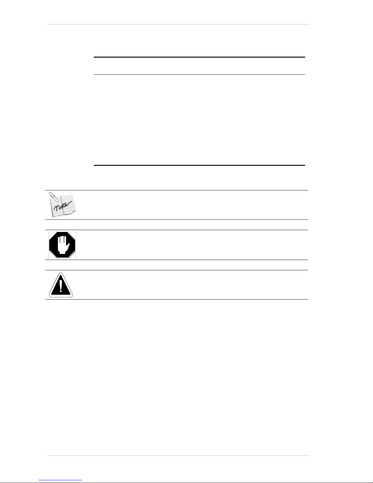
This information is important and should be noted.
Information given in this message warns of a hazard.
Information given in this message refers to the only safe method of installation or
operation and must be adhered to.
Page 17
Important Notes Getting Started
Sprinter User's Manual 1-3
Important Notes
The following notes should be read carefully.
It is recommended that the operator be fully familiar with the specification and all
sections of this manual. Failure to do so may compromise the warranty and the
accuracy that Matan has engineered into your printer.
After relocating he SprinterB printer to a new location, you must ensure that it is
completely level before commencing work.
When any reference is made to the right or left side of the printer, it refers to the
sides when looking from the front of the printer. That is, when you are facing the
Substrate Collector Cover, with the Controls Cover on your right.
Any machine parts or components located on the right side of the printer, are
accessible only after removing the Controls Cover.
You should use the Around the Windows chapter as your Quick Reference Guide.
This chapter contains an explanation of all the application's main windows and
dialog boxes.
The Operating Procedures described in this manual should be carried out in the
order that they are presented.
The photographs appearing in this manual were taken under factory conditions.
Any objects that may appear, other than those refered to in the accompanying
caption, should be ignored.
In some photographs, for clarity, the printer's outer covers were removed.
You are advised that when changing any worn parts or used materials, care should be
taken to dispose of those parts or materials in the correct manner and, where applicable,
they should be recycled according to local regulations.
Page 18

Important Notes Getting Started
1-4 Sprinter User's Manual
This page has been intentionally left blank.
Page 19
Sprinter User's Manual 2-1
2 Overview
Thermal Transfer Printing Technology
The SprinterB Printer uses Thermal Transfer Printing Technology. It has a
solid-state print head with no moving parts. Similar to fax machines, the
print head has 400 "micro hot spots" per inch arrayed horizontally across
the print head. As the substrate passes under the print head, the "micro
hot spots" are turned on and off to create the image on the substrate.
Direct Thermal Printing
The substrate can be thermally sensitive (like fax paper), in which case no
Ribbons are needed. The " micro hot spots" develop a high-resolution image
right on the substrate directly. This is called direct thermal printing.
Thermal Transfer Printing
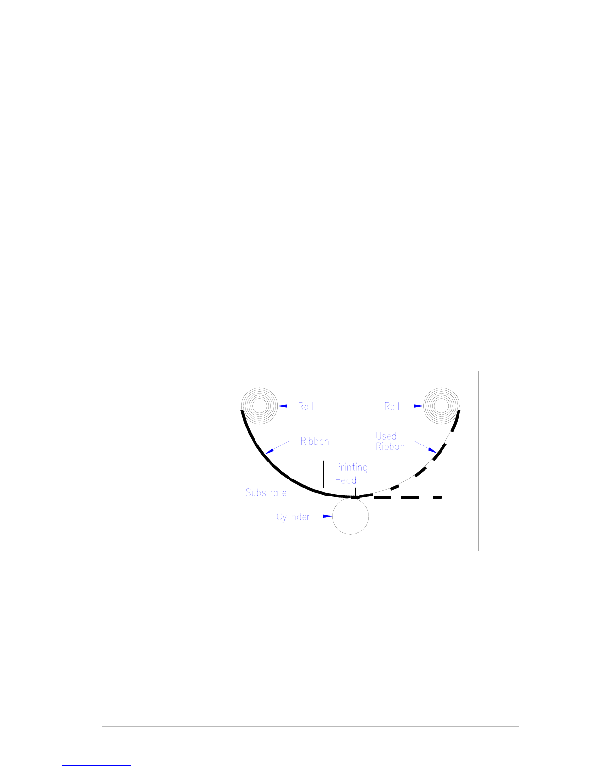
Alternatively, the four Ribbons of the basic YMCK colors can be loaded in
the printer, between the print head and the substrate. The ribbon is thin
film mylar, with an ink surface. As the substrate and ribbon pass under
the print head, the "micro hot spots" on the print head melt the ink off the
mylar ribbon and transfer it to the substrate. This is called thermal
transfer printing.
Figure 2-1: Thermal Transfer Printing
This technology is employed where high resolution, detailed printing is
required and high durability is needed.
YMCK
The combination of Yellow Magenta, Cyan & Black forms ‘color print’. YMC
is a subtractive mixture, in other words, YMC is the three primary colors of
paints. The Black is a supplemental color, because for printing, YMC is
unable to produce a pure Black. This is called the ‘Four Color Process’.
Page 20

Overview
2-2 Sprinter User's Manual
This page has been intentionally been left blank.
Page 21
Sprinter User's Manual 3-1
3 General Description
About the SprinterB Printer
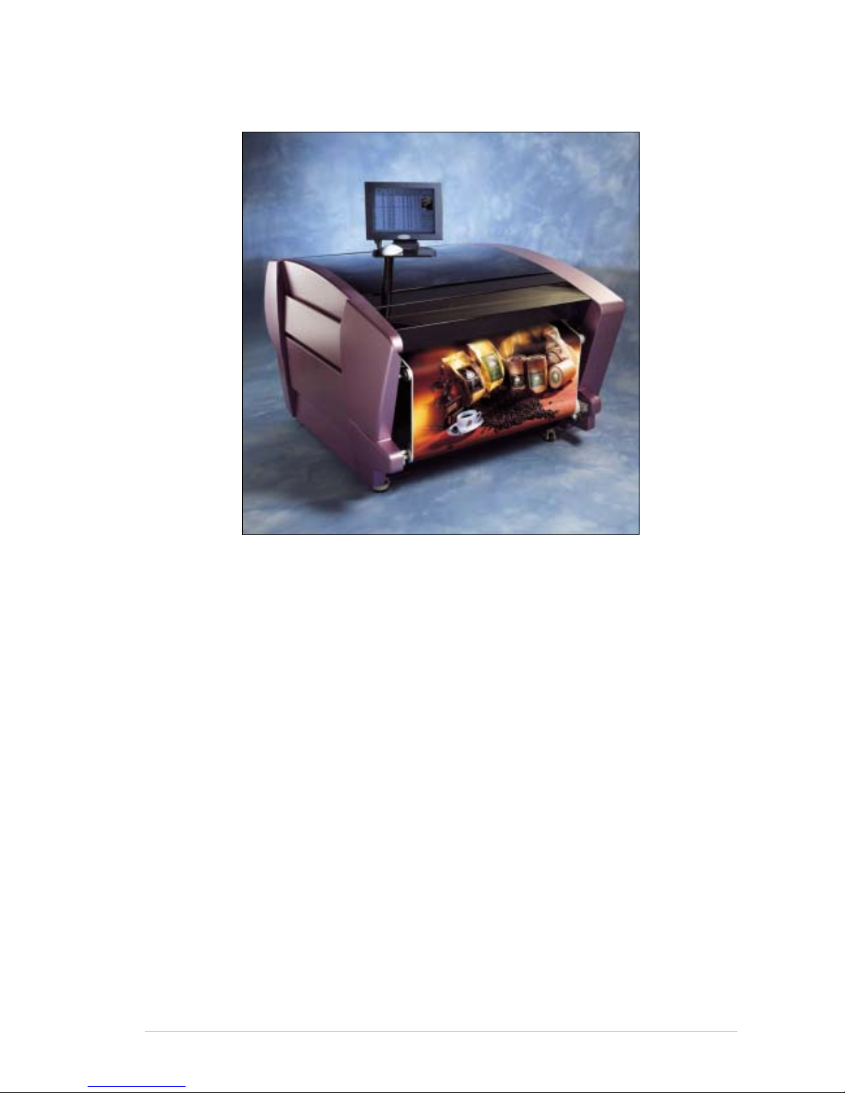
The SprinterB Pr inter integrates the most advanced features of highdefinition quality and high-speed billboard printers. Providing high
throughput and easy integration at low operational cost, the SprinterB
Printer enables you to provide immediate solutions, increase flexibility and
volume of your large format printing output.
The SprinterB Pr inter is one of the fastest large-format printers on the
market today—printing up to 120 running meters per hour (108
2
/hour or
1163 ft
2
/hour).
Hundreds of prints with over 16 million shades can be printed in a single
shift.
Page 22
Technical Description General Description
3-2 Sprinter User's Manual
Technical Description
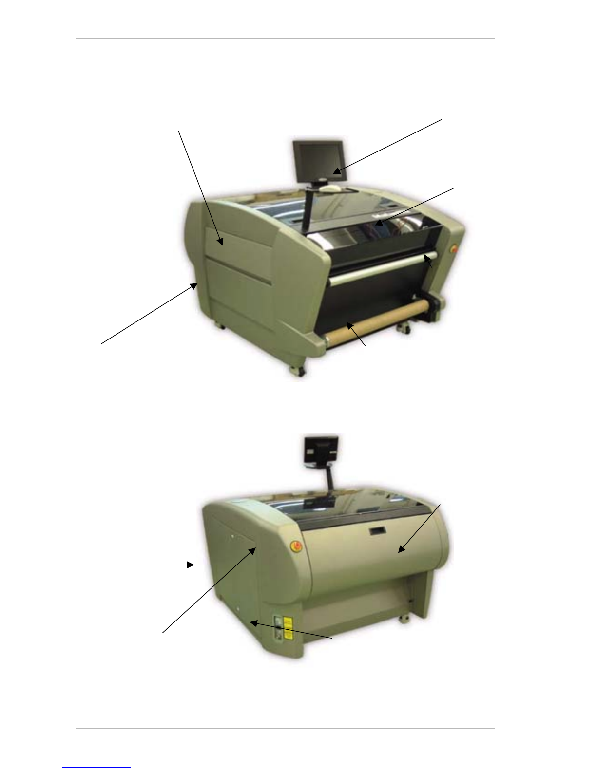
Figure 3-1 is the view from the front left side of the SprinterB Printer.
Figure 3-1: General View of the Front and Left Side of the Printer
Figure 3-2 is the view from the rear right side of the SprinterB Printer.
Figure 3-2: General View of the Rear & Right Side of the Printer
Top Cover
Substrate Pass Door
Service Doors
Emergency Stop
Button
Electric Power Switch
Pneumatic Quick Connector
Rear Cove
r
PC Door
Emergency
Stop Button
Collector Roller
Front Cover
Page 23
General Description Technical Description
Sprinter User's Manual 3-3
The Power Inlet Connection
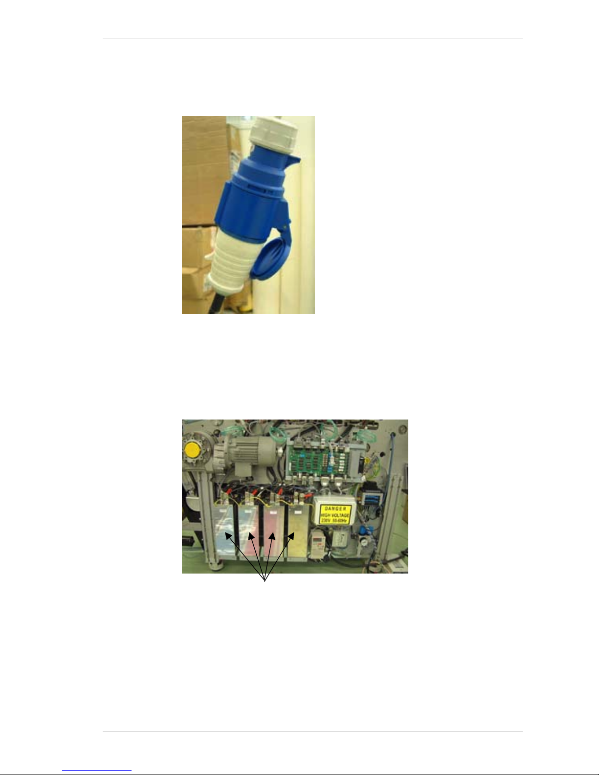
The printer is supplied with a MALE POWER CONNECTOR and should be
connected to the F
EMALE POWER CONNECTOR (also supplied,) that has been
connected to the power box by an authorized technician.
Figure 3-3: The Main Power Connector
Power Supply Units
The printer has four or eight POWER SUPPLY UNITS. They are located on the
right side of the printer, behind the S
ERVICE DOORS FOR TECHNICIAN
(Figure 3-2, page 3-2),as illustrated below.
Figure 3-4: Power Supply Units
(
4 or 8) Power Supply Units
Page 24
Technical Description General Description
3-4 Sprinter User's Manual
The Thermal Print Head (TPH)
The Print Head Subsystem
The PRINT HEAD SUBSYSTEM is located between the SUBSTRATE ROLL and the
S
UBSTRATE ROLL PULLING CYLINDER and lays parallel to them (Error!
Reference source not found.).
The Print Head
The PRINT HEAD comprises micro hot spots, which melt the ink onto the
S
UBSTRATE.
Temperature Control System (LCS)
The TEMPERATURE CONTROL SYSTEM (LCS) maintains the temperature of the
P
RINT HEADS within a preset range, during the printi ng process.
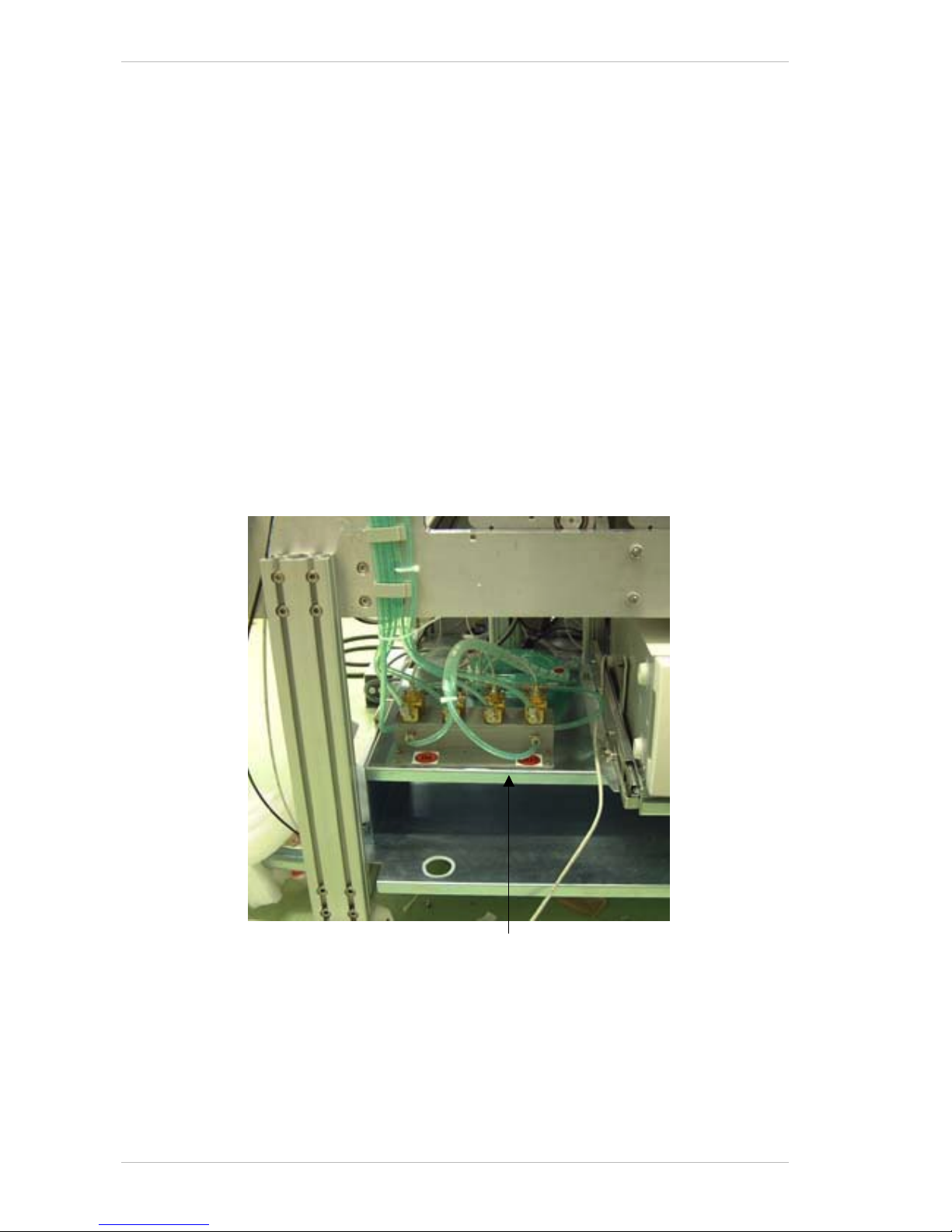
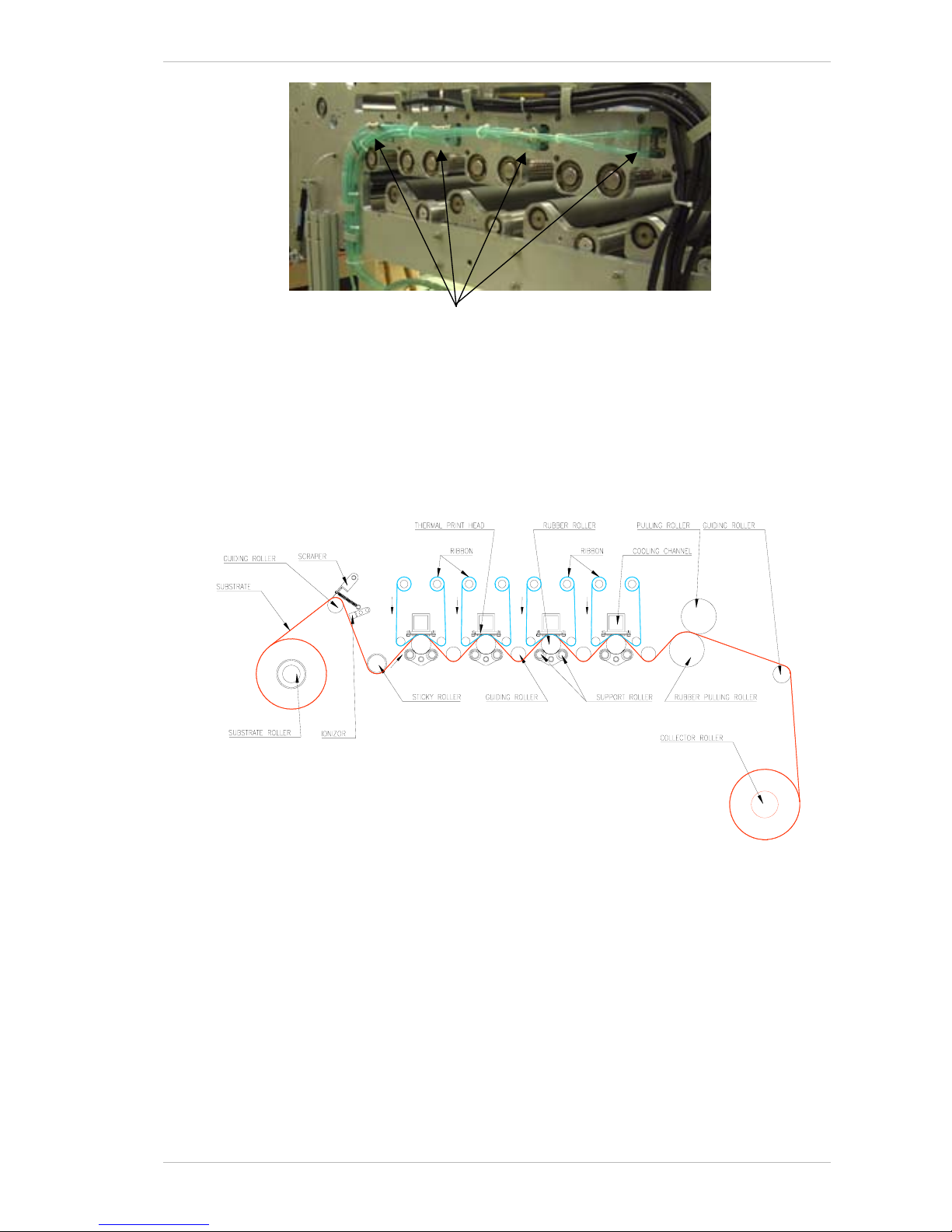
The liquid is cooled by the cooler and is pumped via the L
IQUID COOLING
CONTROL BOX (Figure 3-5) to each of the four aluminum profiles that
support the T
HERMAL PRINT HEADS (Figure 3-6, page 3-5). The LIQUID
COOLING CONTROL BOX is located on the left side of the printer, behind the
PC Door (Figure 3-1, page 3-2), as illustrated below
Figure 3-5: The Liquid Cooling Control Box
Liquid Cooling Control Box
Page 25
General Description Technical Description
Sprinter User's Manual 3-5
Figure 3-6: Liquid Coolant pumped to the Aluminum Profiles
The Ribbon System
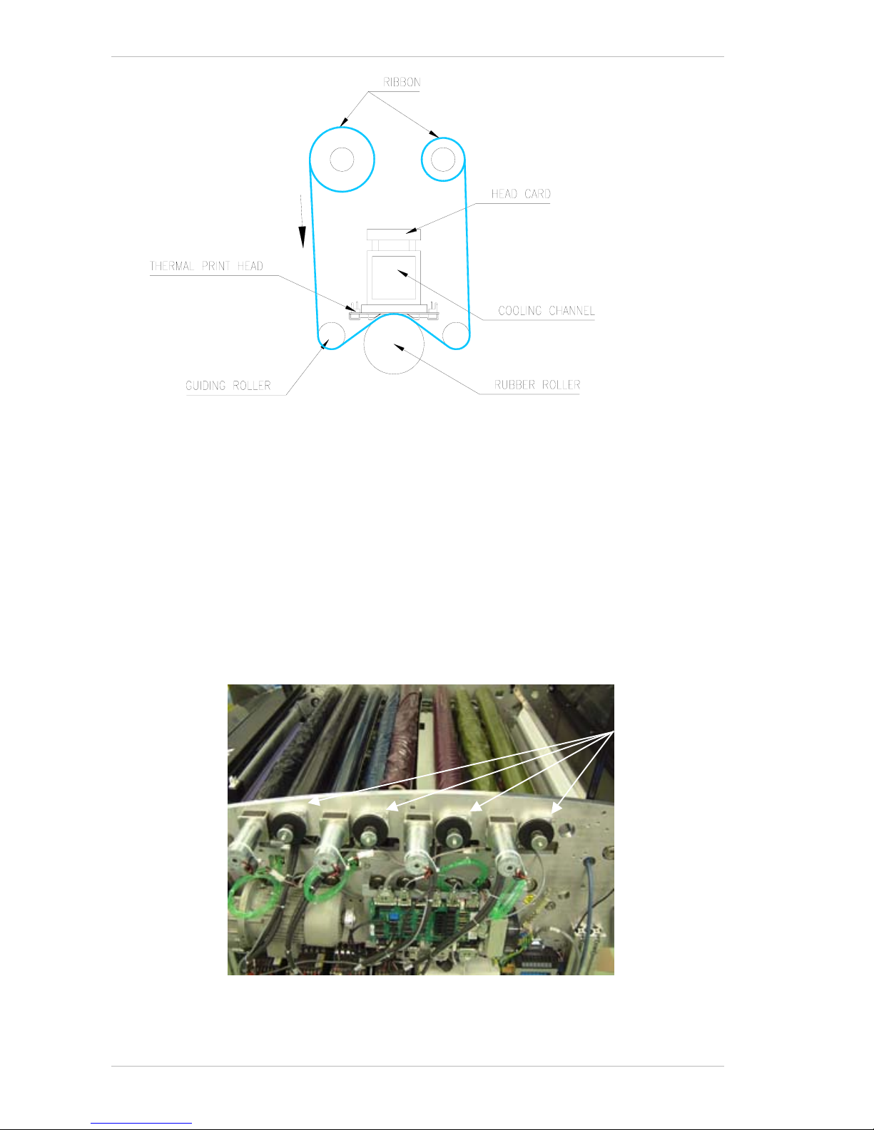
The RIBBON SYSTEM, as illustrated in Figure 3-7and Figure 3-8, page 3-6,
comprises the R
IBBON and the RIBBON TAKE-UP ROLL.
Figure 3-7: The Ribbon and Substrate flow
Four Aluminum Profiles
Page 26
Technical Description General Description
3-6 Sprinter User's Manual
Figure 3-8: The Ribbon flow on a single Print Head
The Ribbon
The RIBBON is a thin mylar film, coated with ink which is transferred to the
S
UBSTRATE.
The Ribbon Motors and Take-up Rolls
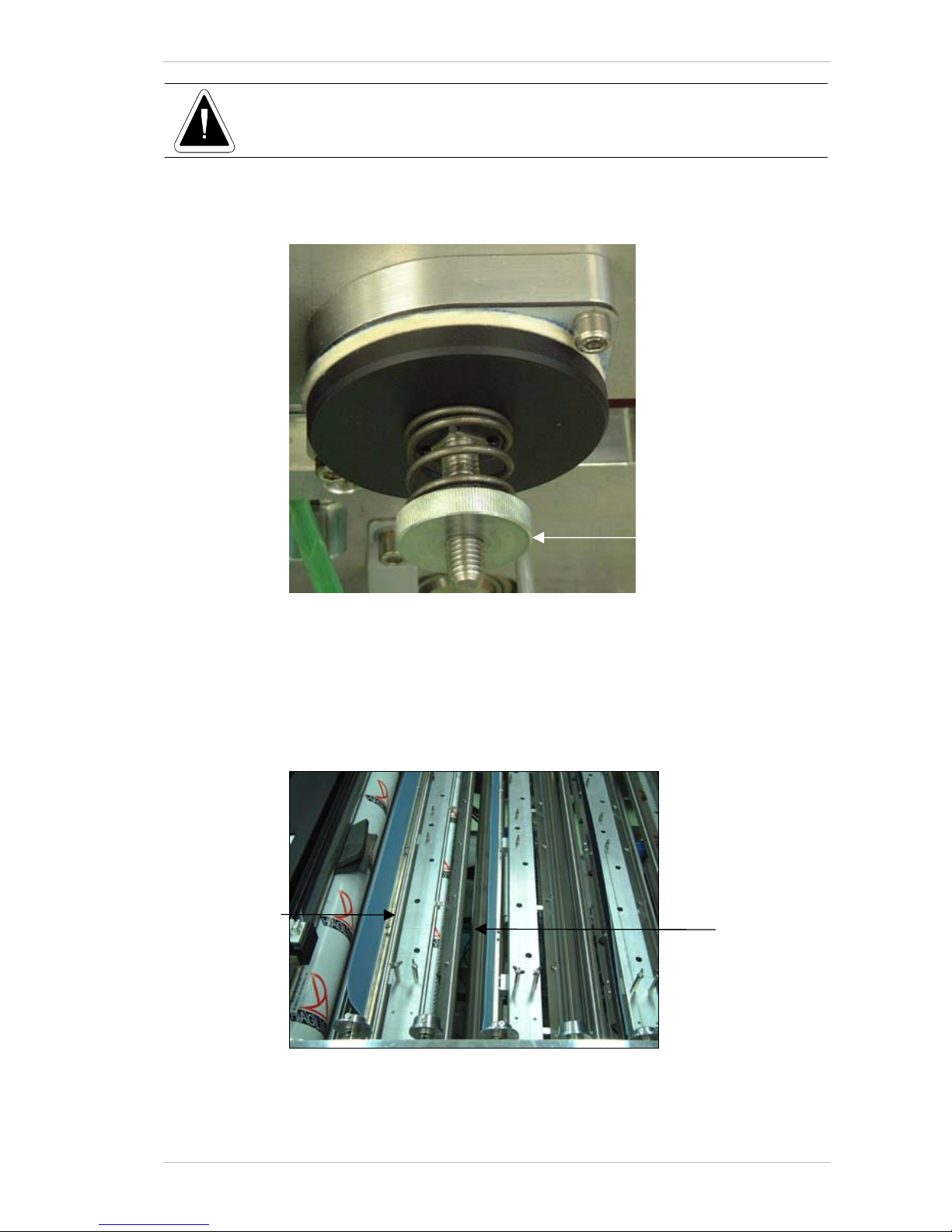
The RIBBON MOTORS drive the RIBBON TAKE-UP ROLLS, which collect the used
R
IBBON.
The Ribbon Brake
The RIBBON BRAKE keeps the corresponding unused RIBBON taut. Each
R
IBBON BRAKE is located to the right of its corresponding RIBBON MOTOR
(Figure 3-9).
Figure 3-9: The four Ribbon Brakes
Ribbon Brakes
Page 27
General Description Technical Description
Sprinter User's Manual 3-7
Please contact our Support Team for instructions before attempting to adjust the
Ribbon Brake.
If you have to make an adjustment to the R
IBBON BRAKE, you must use a
torque-meter. The adjustment is made by turning the K
NURLED THUMB NUT
on the brake to between 80 and 90cN-m (Figur e ).
Figure 3-10: Adjusting the Ribbon Brake
The Anti-static Brush and Strip
An ANTI-STATIC BRUSH and an ANTI-STATIC STRIP are installed close to each of
the four Ribbons.
The brush is located next to the unused R
IBBON, and the strip next to the
used R
IBBON (Figure 3-11, page 3-8).
Figure 3-11: The Anti-static Brush and Strip
Anti-static Strip
Anti-static Brush
Knurled Thumb Nut
Page 28
Technical Description General Description
3-8 Sprinter User's Manual
The Substrate System
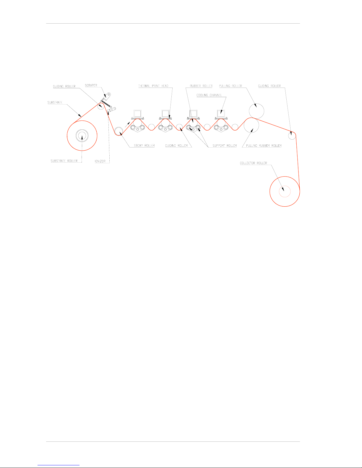
The following figure illustrates the SUBSTRATE path, from the SUBSTRATE
ROLLER to the COLLECTOR ROLLER.
Figure 3-12: The Substrate flow
Page 29
General Description Technical Description
Sprinter User's Manual 3-9
The Substrate Roller
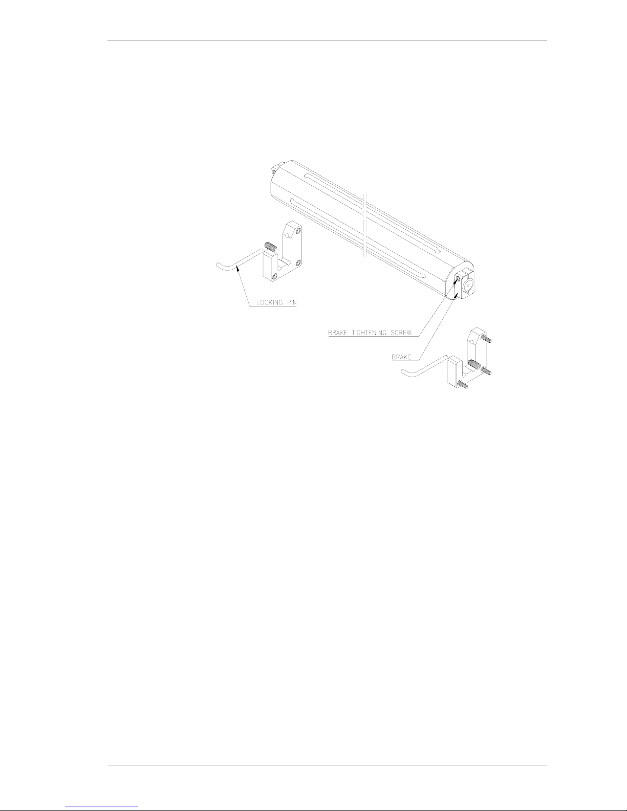
The SUBSTRATE ROLLER is designed to hold 3" (internal) diameter cores.
The L
OCKING PIN secures the SUBSTRATE ROLLER. You must ensure it secures
the S
UBSTRATE ROLLER during printing.
The tension adjusting screw should be turned so that the substrate will
not slide but will have tension while turning (Figure 3-13).
Figure 3-13: The Substrate Roll Holder
The Pulling System
The PULLING SYSTEM comprises the SUBSTRATE PULLING CYLINDER and the
P
RESSING ARM.
The Substrate Pulling Cylinder and Pressing Arm
The SUBSTRATE PULLING CYLINDER is driven by a motor and pulls the
Substrate between the various rollers and under the P
RINTER HEADS. The
P
RESSING ARM applies pressure to the SUBSTRATE and facilitates its moving
over the S
UBSTRATE PULLING CYLINDER.
Page 30
Technical Description General Description
3-10 Sprinter User's Manual
The Substrate Collecting System
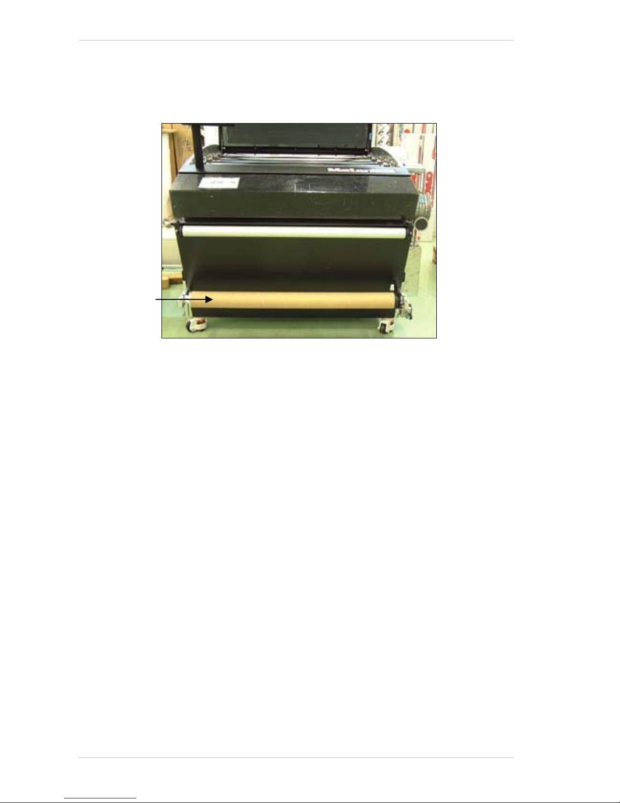
The SUBSTRATE COLLECTING SYSTEM receives the printed material from the
SprinterB Printer and collects it into a roll (see Figure 3-14).
Figure 3-14: The Substrate Collecting System
The Pressure Rollers Pistons
The PRESSURE ROLLER PISTONS raise and lower the PRESSURE ROLLERS.
The Pressure Rollers System
The PRESSURE ROLLERS press the SUBSTRATE and the RIBBONS against the
P
RINT HEAD.
Substrate
Collector Roller
Page 31
General Description Technical Description
Sprinter User's Manual 3-11
The Optic Sensor
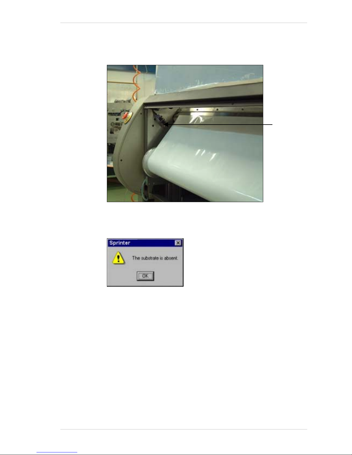
The OPTIC SENSOR monitors the presence of the SUBSTRATE. It does not
monitor transparent S
UBSTRATES.
Figure 3-15: The Optic Sensor
When the end of the S UBSTRATE is detected, the SUBSTRATE ABSENT window
appears (Figure 3-16).
Figure 3-16: The Substrate Absent Window
The printers stops an d c arries out the unload procedure.
Any unprinted file will be saved and will remain on the P
RINT MENU. The file
that was being printed when the printer stopped will be saved.
Optic Senso
r
Page 32
Technical Description General Description
3-12 Sprinter User's Manual
The Scraper and Ionizor
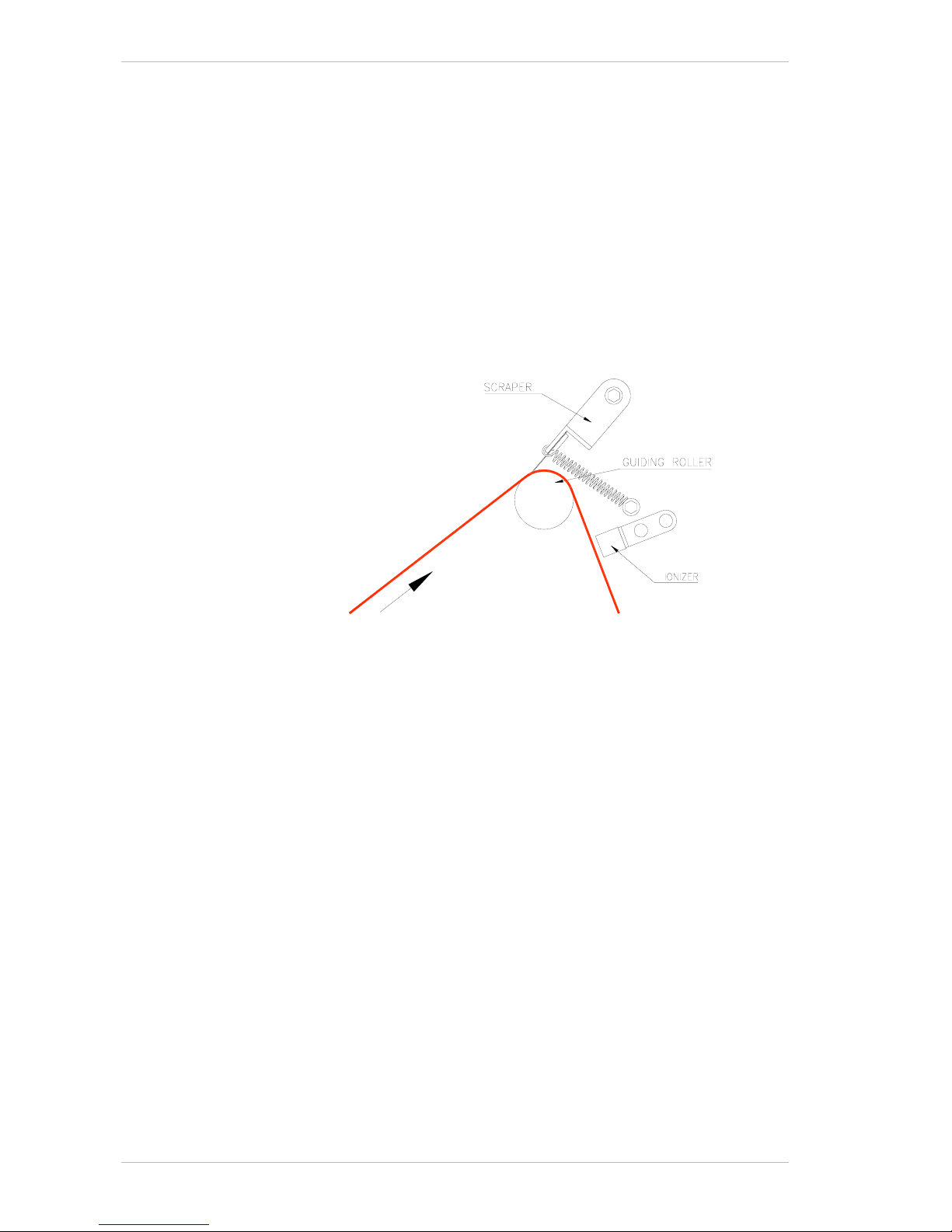
The SCRAPER is constantly applied to the SUBSTRATE to ensure that the
S
UBSTRATE is kept free of dirt and dust particles.
The I
ONIZOR is located between the SCRAPER and the STICKY ROLLER. Its
Power Unit is located underneath it, on the inside base of the printer.
It neutralizes electro-static charge from the S
UBSTRATE.
The I
ONIZOR works when a voltage of 24v is present. When possible, the
24v voltage should be turned off. If the voltage is left on unnecessarily, the
Ionizor will leave a mark on the Substrate.
Figure 3-17: The Scraper and Ionizer
The SprinterB PC Control Station
The SPRINTERB PC CONTROL STATION controls all the operation and printing
operations. It is located behind the PC D
OOR (Figure 3-1, page 3-2).
Network
The SPRINTER PC CONTROL STATION controls all the printer's operations.
The computer includes a network card. It is ready to become a station on a
LAN in any environment. It has also an address that is already set so it will
not conflict with any other device on the system.
There are many dif fer en t n etw or ks sy st em s on t h e ma r ket a nd t h er ef or e w e
do not configure the computer to any specific system. If the system in the
target customer's pl a ce is known when ordering the printer, we can set
and configure the c o mputer to these needs.
If not, than a network technician will have to set the configuration on-site
according to the system used.
Your Systems Administrator who knows the environment well, is
responsible for connecting the printer to the LAN, and not our technician.
Page 33
General Description Technical Description
Sprinter User's Manual 3-13
The Emergency Stop Buttons
The printer is equipped with two EMERGENCY STOP BUTTONS. One of which is
located at the front of the printer and the other, at the rear. (See
Figure 3-1, page 3-2 and Figure 3-2, page 3-2).
These buttons operate manually, and when pressed, all power SHUT S
OFF.
E
MERGENCY STOP BUTTONS should be activated in any emergency situation.
To release the E
MERGENCY STOP BUTTONS, turn the button to the left and
push the button next to the C
IRCUIT BREAKERS at the MAIN SWITCH BOX.
Any unprinted file will be saved and will remain on the P
RINT MENU. The file
that was being printed when the printer stopped will be saved in its
entirety.
The Safety Micro Switches
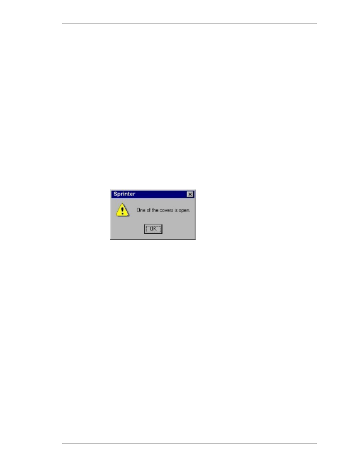
The printer is equipped with five SAFETY MICRO SWITCHES. Each switch is
located adjacent to a cover. When a cover is open, the printer will not
operate. Its S
AFETY MICRO SWITCH is activated, and a warning appears on
the screen, as illustrated below..
Figure 3-18 The Open Cover Warning Window
Page 34
Technical Description General Description
3-14 Sprinter User's Manual
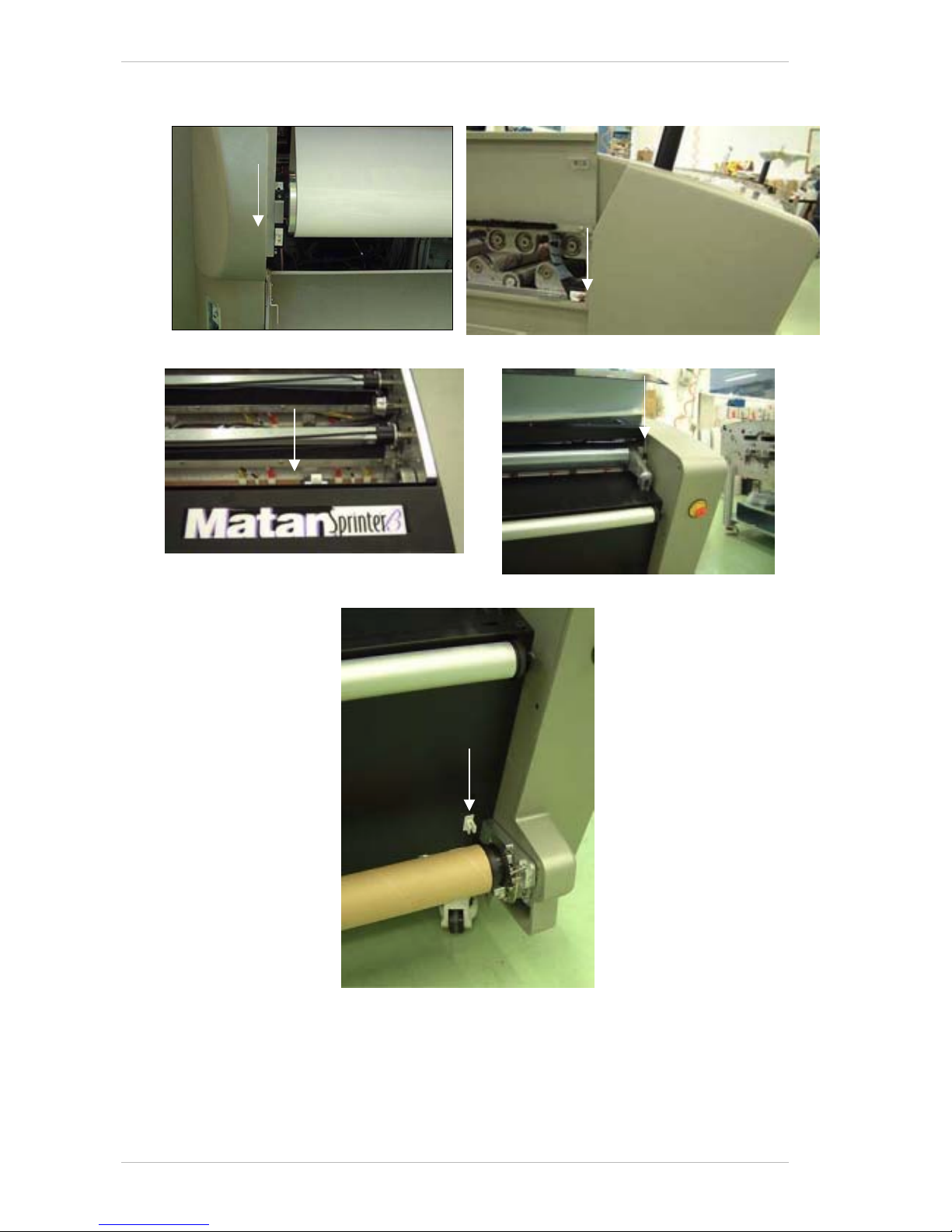
Figure 3-19 illustrates the location of the five SAFETY MICRO SWITCHES,
indicated by white arrows.
Behind the Rear Cover Behind the Substrate Pass Door
Under the Top Cover Under the Front Cover
Under the Substrate Collector Mechanism Cover
Figure 3-19: Location of the five Safety Micro Switches
Page 35

Sprinter User's Manual 4-1
4 Specifications
General
Remarks
Printer dimensions 36" 40"
Unpacked:
1660 x 1340 x 1150 (mm)
(65.35" x 52.76" x 45.28")
(L x W x H)
Unpacked:
1660 x 1450 x 1150 (mm)
(65.35" x 57.09" x 45.28")
(L x W x H)
Packed:
2055 x 1555 x 1400
(80.91" x 61.22" x 55.12")
(L x W x H)
Packed:
2055 x 1665 x 1400
(80.91" x 52.76" x 65.55")
(L x W x H)
Gross weight
500kg (1102.6lbs) 550kg (1213lbs)
Substrate size
90.5cm (width) x 24cm (Ø)
35.6” (width) x 9.4” (Ø)
1020mm (width) x 24cm (Ø)
40.16” (width) x 9.4” (Ø)
Effective print width
902mm (35.5") 1016mm (40")
Max. Print speed
60m/hr
(196.86 feet/hr)
54.12m
2
/hr
(582.5ft
2
/hr)
60m/hr
(196.86 feet/hr)
60.96m
2
/hr
(656.2ft
2
/hr)
Printing Method
4 color process (YMCK)
3 color process (YMC)
Spot Colors
Ink Ribbon length
Resin/Wax Ribbon: 36"/40" x 500m
Spot Colors: 36"/40" x 150m
Dye-Sublimation: 36"/40" x 150m
Shades
18 million
Substrate Handling
Roll-to-roll printing
Image data Format
TIFF Bitmap: 200/400 DPI
TIFF: 50 DPI
Work Flow
TIFF (50 DPI) No RIPing time (RIPs
on the fly). TIFF Bitmap
files (200/400dpi) EPS
or Postscript files can
be RIPed on an
external standard
supported RIP.
Hardware Image
Processing
On-the-fly
Printed material
High resistance to Water and UV light
Direct printing
Variety of substrates such as paper, vinyl and polyester
Coating or lamination
None required
Resolutions
400, 200, 50 dpi
RIP Softwarer
PPS RIP software
Page 36

Electrical System Specifications
4-2 Sprinter User's Manual
Electrical System
Electrical Input 200-230VAC, 50/60Hz, single phase
Power
Consumption
25A (Max)
Display
Monitor 12.1”
Viewable image size.
Electronic System
RIP card
The rip card processes the file before printing and controls
the angles of screens, the color LUT, the characters as well
as the resolution (400 dpi, 200 dpi and 50 dpi) for each print
head.
I/O card
This controls the Pistons and the sensors’ indicators and is
located in the Electronic Box, behind the front cover of the
printer. It also controls all the motors of the printer (Ribbons
and Substrate) as well as on the power input (24V)
Print head card
Controls the operation of the Print Head and is located
above the print Head.
Filter
30A, 120/250VAC 50-60 Hz -10°c - 40°c
Driver
Phasing
Circuit Breaker
C25/230V
PC Station
Operating System
Windows NT (minimum SP6)
CPU
Pentium 4 1.7GB
Hard Disk
30GB
Memory
256MB
Network card
10/100
Page 37

Air Compressor Specifications
Sprinter User's Manual 4-3
Air Compressor
Air Compressor
5.5 Bar
Air supply flow rate
50 ltr/min
We recommend you to install an air dryer in addition to the air compressor and
locate it between the compressor and the printer.
We also recommend you to connect the air compressor and the air dryer to
separate phases from the printer.
Temperature Control System (TCS)
Cooling Capacity
16,000 BTU/Hr minimum for SprinterB 36”
20,000 BTU/Hr minimum for SprinterB 40”
Liquid Outlet Temp
15°C
Liquid
Motor cooling liquid (anti-freeze) – recommended, or water.
Flow Rate
5–10 GPM
LCS location
Indoor, 3–5m from the printer
Connection
Requirements
Inlet: flexible tube – 8mm outside dia, 6mm inside dia.
Outlet flexible tube – 8mm outside dia, 6mm inside dia.
We recommend that you consult with your local chiller provider for the above
requirements. Further information is available for example, at
http://www.liquidchillers.com.
Pneumatics
Air supply pressure
4 Bar (36”) 4.5 Bar (40”)
Air supply flow rate
50 ltr/min
Operating Conditions
Temperature
20°c-28°c (Room temperature)
Humidity
40% to 70% (Room humidity)
Page 38

Substrate Specifications and Storage Specifications
4-4 Sprinter User's Manual
Substrate Specifications and Storage
As per manufacturers’ specifications & instructions.
Make sure you keep the substrates in a clean area, wrapped in nylon bags.
Ink Roller (Ribbon) Specifications and Storage
Shelf life
The Ribbons' shelf life is determined by the storage conditions and is
summarized in the following table.
Conditions Resin Ribbon Wax Ribbon
Storage Conditions
Short term
Long term
50°C 85%RH 24HR
* - 20°C 24HR
0 ~
40°C
1 year
50°C 85%RH 24RH
* - 20°C 24HR
0 ~
35°C
1 year
Operating
Conditions
5 ~
35°C
10~85%RH
5~
35°C
10~85%RH
* If the Ribbons were kept at a low temperature, ensure that there is no
condensation on the film before commencing printing.
New as well as used Ribbons should be stored in their original packing.
Page 39
Sprinter User's Manual 5-1
5 Installing the Software
This chapter details the software installation procedure.
Installing the Software
You download the Matan software from out Web site.
To download and Install the SprinterB Software:
1. Open our Web site www.matan.co.il
.
2. Click T
ECHNICAL SUPPORT.
The T
ECHNICAL SUPPORT Page opens.
3. Click L
OG IN TO THE MEMBERS’ AREA.
The L
OG IN window appears.
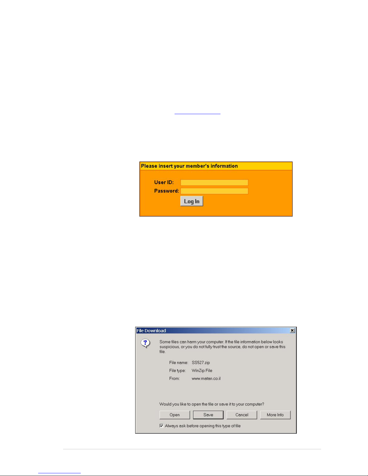
4. Enter your username (not case sensitive) and password you received
from your Matan distributor.
5. Click L
OGIN.
The D
OWNLOADS AREA page opens.
6. Click S
OFTWARE DOWNLOADS.
The S
OFTWARE DOWNLOADS page opens.
7. Click S
PRINTER & SPARK SOFTWARE.
The D
OWNLOADS AREA page opens.
8. Enter your personal information as requested and click C
ONTINUE
DOWNLOAD.
The F
ILE DOWNLOAD window opens.
Page 40
Installing the Software Installing the Software
Sprinter User's Manual 5-2
9. Click SAVE.
10. Save the zip file to the temp directory.
The download procedure starts.
11. When the download has been completed, extract the zipped file to a
convenient directory.
12. Double click the expanded .exe file.
The W
INZIP SELF-EXTRACTOR window opens.
13. Click S
ETUP.
The S
ETUP WIZARD is activated.
14. Follow the on-screen instructions.
15. Select the type of printer for which you are installing the software and
click OK.
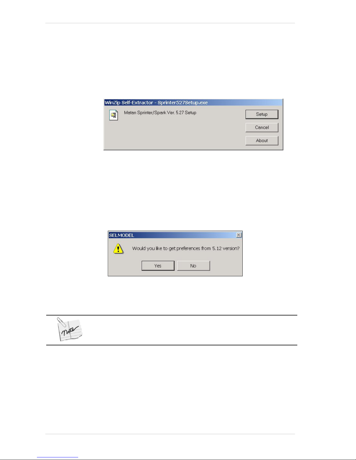
If you have a previous NT setup version already installed on your
printer, you can move all your preset parameters (delay, shift, etc.,)
from the existing software to the new version, by click Yes in the
SELMODEL window as illustrated below.
The I
NSTALLATION window closes and the new software icon (Sprinter or
Spark) appears on your Desktop.
16. To activate the program, double-click the icon.
The Encoder Division and Main Motor Coefficient parameters must be checked
immediately after the software installation. This is done through the Preferences
dialog box (see the Setting the Preferences section).
Page 41
Sprinter User's Manual 6-1
6 Around the Windows
This chapter describes all the main functions of the software and
illustrates most of the windows and dialog boxes that you see while
working in the application.
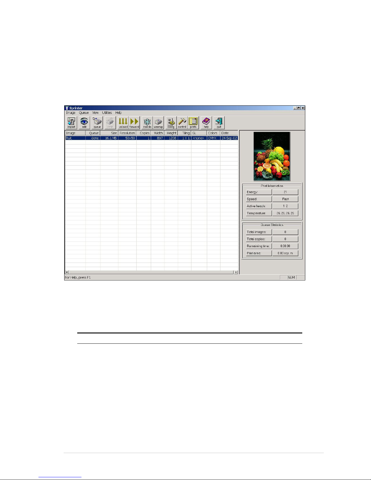
About the SprinterB Main Screen
Figure 6-1: The SprinterB Main Screen
The Menu Bar
The MENU BAR gives you access to different tools and functions.
Use this Menu To.... Shortcut
Image Import
Edit
Rotate 90°
Rename
Delete
Delete Done
Print
Exit
Ctrl+I
Ctrl+E
Ctrl+9
Ctrl+R
Ctrl+D
Ctrl+P
Alt+F4
Page 42
The Tool Bar Around the Windows
6-2 Sprinter User's Manual
Use this Menu To.... Shortcut
Queue Add First
Add Last
Add Manual
Remove
Remove All
Ctrl+Home
Ctrl+End
Ctrl+Ins
Ctrl+Del
View View Toolbar
View Status Bar
Utilities Access:
The Configuration Dialog Box
The Control Dialog Box
The Preferences Dialog Box
The Warm Up Dialog Box
The Cool Down Dialog Box
Advance the Substrate
Unload
Update the Service Code
F5
F6
F7
F8
F9
F10
F11
F12
Help Get help
About Application Version Number
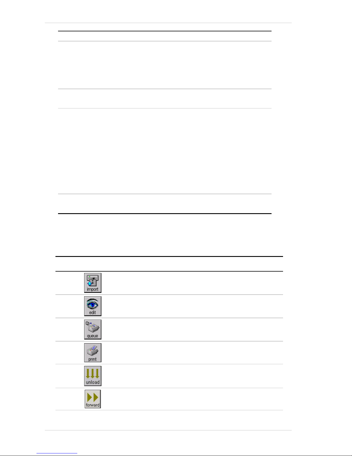
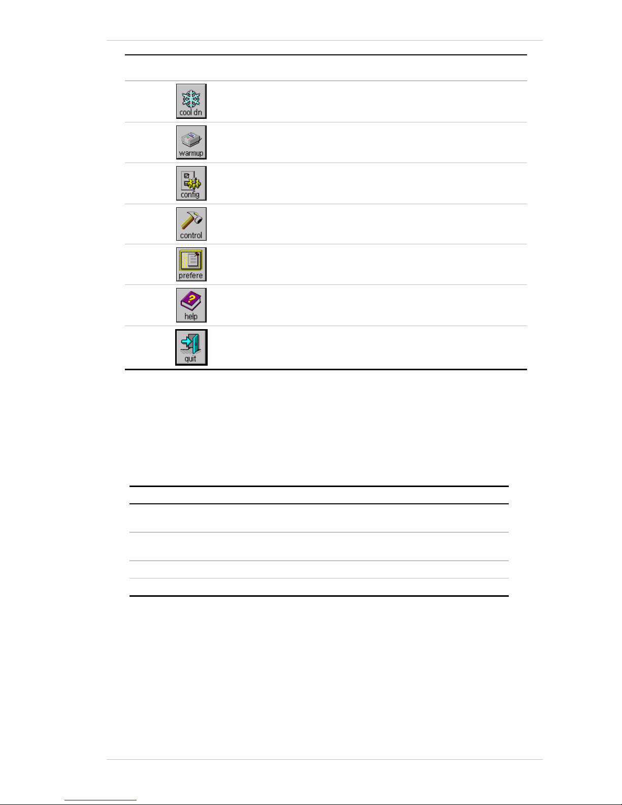
The Tool Bar
The TOOL BAR gives you quick access to the most used commands.
Click this Icon To....
Access the Import File Dialog Box.
Access the Edit Dialog Box.
Access the Enqueue Dialog Box.
Automatcially load the system and print the selected file(s).
Unload the system.
Advance the Substrate.
Page 43
Around the Windows The Main Screen Information Center
Sprinter User's Manual 6-3
Click this Icon To....
Access the Cool Down Dialog Box.
Access the Warm Up Dialog Box.
Access the Configuration Dialog Box.
Access the Control Dialog Box.
Access the Preferences Dialog Box.
Access the On-Line Help facility.
Close the Application.
The Main Screen Information Center
The lower right-hand section of the MAIN SCREEN provides you with current
information about the Printer. There follows an explanation of each of the
two parts of this section.
Print Information
Information item Description
Energy The energy level at which the Print Heads are currently
printing the color on the Substrate.
Speed Is the speed in running meters per hour,(m/h) that the
SprinterB Printer will print the current Images.
Active Heads Indiction of which Printing Heads are active.
Temperature Indiction of the Printing Heads’ temperature.
Page 44

The Printing Information Center Around the Windows
6-4 Sprinter User's Manual
Queue Statistics
Information item Description
Total Images The total number of Images that you have placed in
the printing queue.
Total Copies The total number of copies that you have ordered for
printing.
Rest Print Time The remaining time it will take for the Images that have
been queued, to be printed.
Print Area The area that will be printed of the current file.
The Printing Information Center
The lower left-hand section of the MAIN SCREEN provides you with current
information regarding the Images that have been imported or selected for
printing. There follows an explanation of this section.
The Printer Queue Window
The column header buttons can be used to sort the entire table in
ascending or descending order, based on the column selected.
Column Header Description
Image The file name of the selected Image.
Queue The number in the Printing Queue in which the
selected Image stands.
Size The file size of the selected Image (in MBs).
Resolution Displays the Image's resolution.
Copies Is the number of copies of the selected file, to be
printed.
Width Is the width of the Image.
Height Is the height of the Image.
Tiling Indicates if the Image has been set to be tiled, and if
so, how many tiles.
GL Indicates if the Image has been set with a Gray Level.
This feature is only for use with 50n dpi TIFF files.
Colors Indicates which colors are to be used. (If there is no
information regarding a particular color, for example,
black then the combination ‘CMY’ will be displayed.)
Date The date on which the Image was imported into the
Image Print Menu.
Page 45
Around the Windows The Image Menu
Sprinter User's Manual 6-5
The Image Menu
You access the IMPORT FILE dialog box, by choosing IMPORT from the IMAGE
menu or by clicking I
MPORT in the MAIN SCREEN.
The Import File Dialog Box
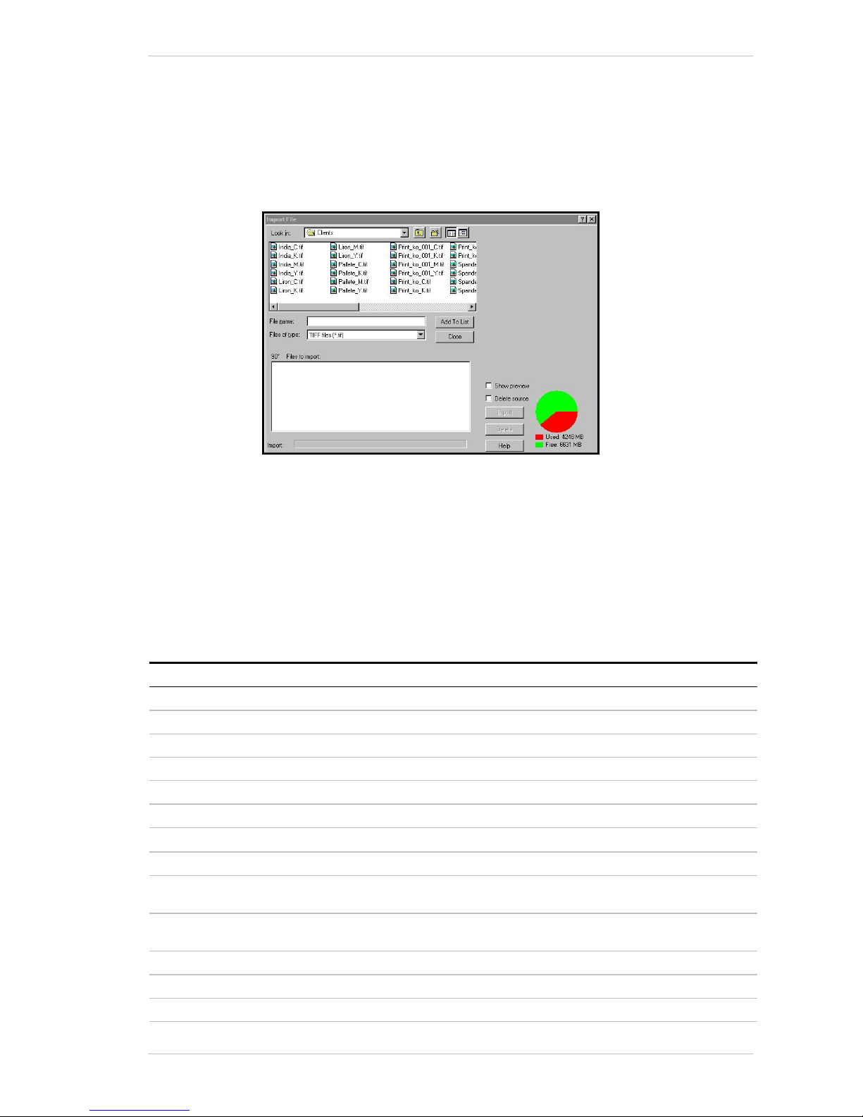
Figure 6-2: The Import File Dialog Box
You use the IMPORT FILE dialog box for importing a file and adding it to the
list of files in the P
RINTER QUEUE window. The selected file can also be
viewed in this dialog box. Selecting the 90° option, after choosing the
required file, will rotate the image clockwise through 90°.
This dialog box also displays the amount of free and used space on the
current drive, after the files required for printing have been imported onto
it.
The following table describes the components contained in the I
MPORT FILE
dialog box.
Screen Component Description
Look in The directory containing the required files.
Upper Window Displays a list of files available in the selected directory.
File Name Name of the file you wish to import to the print list.
File Type The file type you wish to import to the print list.
Add to List Adds the selected file to the import list.
Close Closes this dialog box.
90° Rotates the selected file through 90° (clockwise).
Files to import Displays a list of files selected for importing.
Show preview Displays a preview of the selected file in the upper right section of
the dialog box.
Delete source Deletes the selected file form its source location and processes it
for printing.
Import Imports all the files listed in the Files to import window.
Delete Deletes the selcted file from the Files to import list.
Help Displays the online Help.
Page 46
The Image Menu Around the Windows
6-6 Sprinter User's Manual
Screen Component Description
Used/Free Status of used/free memory on the PC's currently used disk, (path
shown in the Configuration dialog box,)
after the files required
for printing have been imported onto it.
The Edit Dialog Box
You access the EDIT dialog box, by choosing EDIT from the IMAGE menu or
by clicking E
DIT in the MAIN SCREEN.
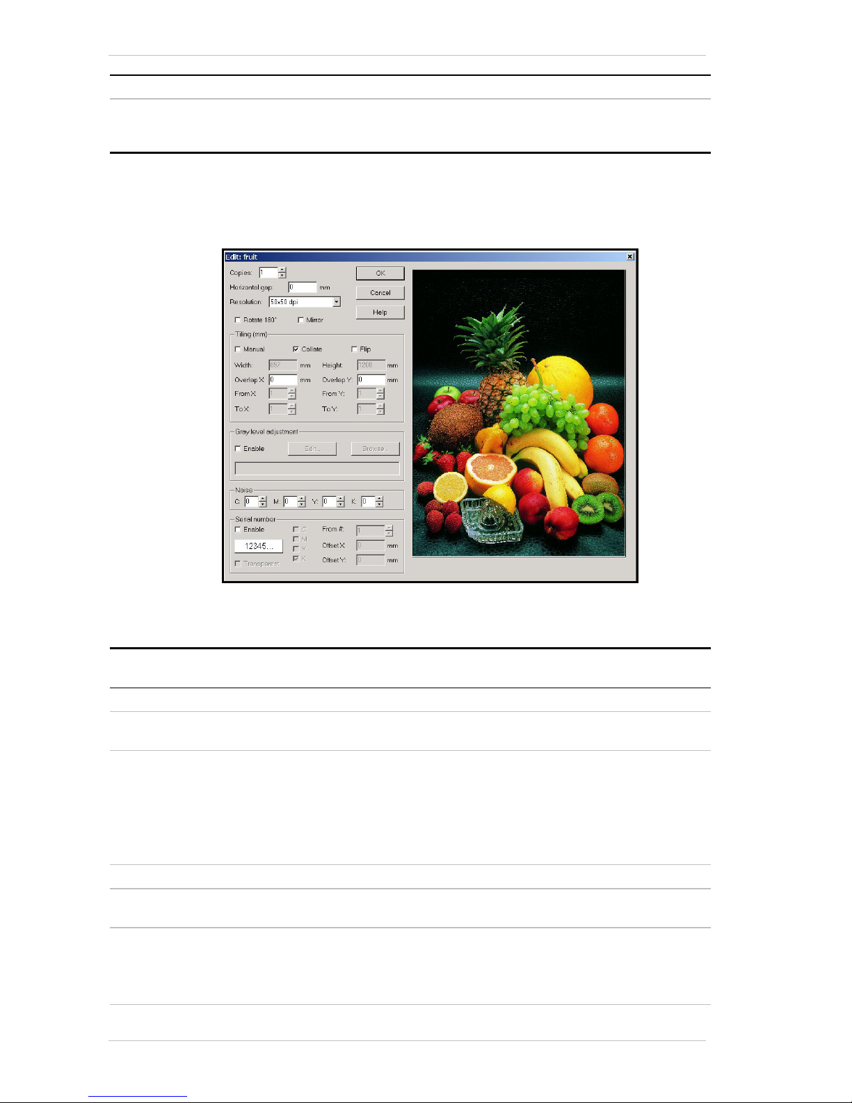
Figure 6-3: The Edit Dialog Box
You use the EDIT FILE dialog box for editing the file’s properties.
Group Box Screen
Component
Description
General Copies Selects the number of copies to be printed.
Horizontal gap Specifies the gap between duplicate images, across the width
of the substrate.
Resolution The current resolution of the selected file is displayed by
default.
The resolution of the image can be increased and the physical
size can be decreased by a factor of 2, as follows:
50 – 25 dpi
200 – 100 dpi
400 – 200 dpi.
Rotate 180º Check this option to rotate the image through 180°.
Mirror Check this option to mirror the print. Used when the image is
to be adhered to a transparent surface.
Tiling Manual Check this option to manually define the slice size. Each slice
except the last one, must be of equal measurement.
Define which slices are to be printed by seklected the required
number from the From X/Y and To X/Y fields.
Page 47

Around the Windows The Image Menu
Sprinter User's Manual 6-7
Group Box Screen
Component
Description
Collate Check this option to ensure that when printing two or more
copies off a file that is tiled, successive tiles of each copy are
printed (starting from Tile #1). The printer then prints the next
copy (starting from Tile #1), etc., etc.
Flip Click this button to activate the flipping feature.
When printing a very large image, in order to maintain color
consistency between the slices, the printer will flip each
alternate (even) slice through 180°.
Width The printed width of each slice. Print width can be set to one
decimal point for better accuracy.
The unit if measure can be specified in the Preferences dialog
box.
Overlap X To set the Slice Overlap. This overlap can be set to one
decimal point for better accuracy
From X To select the first slice to be printed, from the X axis.
To X To select the last slice to be printed from the X axis.
Height The printed height of each slice. Print height can be set to one
decimal point for better accuracy.
The unit if measure can be specified in the Preferences dialog
box.
Overlap Y To set the Slice Overlap. This overlap can be set to one
decimal point for better accuracy
From Y To select the first slice to be printed, from the Y axis.
To Y To select the last slice to be printed from the Y axis.
Grey level
adjustment
Enable Check this option to enable the grey level adjustment feature
for the selected Image.
For 50 dpi TIFF files only.
Edit Click this button to access the Grey Level dialog box.
Browse Click this button to browse for an existing Grey Level file.
Noise To disguise any repetitive errors that appear in the printing,
such as those resulting from bending, in 50dpi files only.
Serial Number Enable Optional feature. Enables you to print a serial number on the
image at a specified location, on top of whatever might be
printed.
Transparent Choosing this option will ‘clean’ the specified location in the
shape of the serial number, which will then be printed on the
Substrate.
C, M, Y, K To select the color in which the Serial Number will be printed.
From # To select the first number that is printed.
Offset X:
Offset Y:
The coefficient location.
The coefficient location.
General OK Click this button to acccept your settings and close the dialog
box.
Cancel Click this button to close the diaslog box without saving your
settings.
Help Click this button to access the online Help.
Page 48
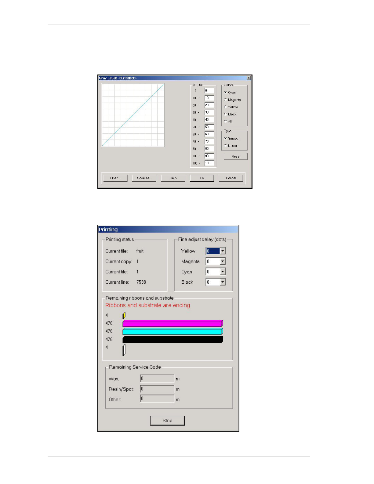
The Image Menu Around the Windows
6-8 Sprinter User's Manual
The Gray Level Dialog Box
You access the GRAY LEVEL dialog box from the EDIT dialog box.
The G
RAY LEVEL feature gives you basic color management within the
image.
Figure 6-4: The Gray Level Dialog Box
The Printing Window
Figure 6-5: The Printing Window
Page 49
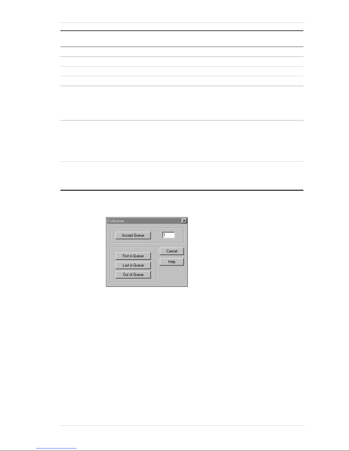
Around the Windows The Image Menu
Sprinter User's Manual 6-9
Group Box Screen
Component
Description
Printing Status Current file The name of the file that is currently being printed.
Current copy The number of the file’s image that is currently being printed.
Current tile The tile of the file that is currently being printed.
Current line The line of the image that is currently being printed.
Fine adjust
delay (dots)
Although the HEAD DELAY feature is accessible from the
CONFIGURATION dialog box for setting before a print session,
you can also adjust the H
EAD DELAYS while printing, through
the PRINT command. This is called ONLINE HEAD DELAY
adjustment.
Remaining
Ribbons and
Substrate
Graphically and numerically displays the amount of Ribbon
and Substrate that currently remains on the printer.
A warning appears in red, when the quantity of any Ribbon
has reached 10m, and 5m of the Substrate.
There is a tolerance of ± 5% for the above quantities.
Remaining
Service Code
Wax
Resin/Spot
Other
Disaplays the amount of each Ribbon type you have left on
your Service Code.
The Queue Dialog Box
Figure 6-6: The Enqueue Dialog Box
You use the ENQUEUE dialog box for setting the position in the printing
queue of the selected file.
This dialog box can also be accessed by clicking the right mouse button,
with the cursor over the required file.
Page 50
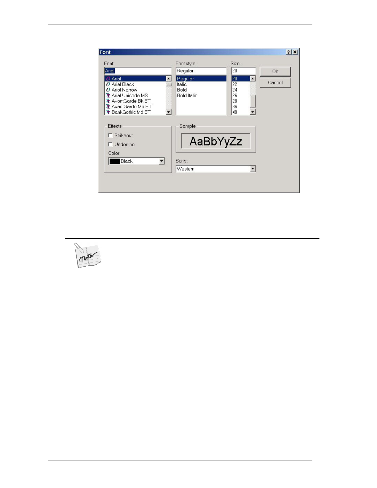
The Image Menu Around the Windows
6-10 Sprinter User's Manual
Serial Number Font Dialog Box
Figure 6-7: The Serial Number Font Dialog Box
You use the SERIAL NUMBER FONT dialog box to specify the font format of
the S
ERIAL NUMBER, but not its color.
You cannot specify the Serial Number’s color from this dialog box.
You access this dialog box by clicking the S
ERIAL NUMBER button (12345…)
in the E
DIT dialog box.
Page 51
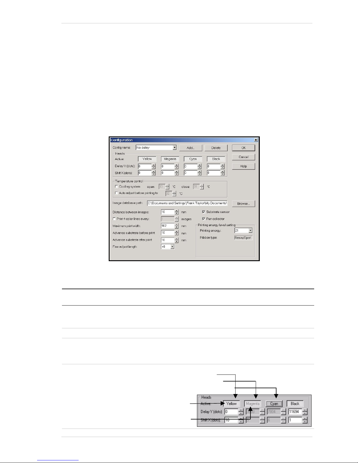
Around the Windows The Utilities Menu
Sprinter User's Manual 6-11
The Utilities Menu
The Configuration Dialog Box
You access the CONFIGURATION dialog box from the UTILITIES menu or by
clicking the C
ONFIG icon in the tool bar.
You can carry out a comprehensive configuration of your SprinterB Printer
from the C
ONFIGURATION dialog box.
The various settings for the P
RINT HEADS are made in this box, as well as
those for specifying the S
UBSTRATE type, and INK type.
Various print measurement settings are made in this dialog box as well.
Figure 6-8: The Configuration Dialog Box
You make the following selections from the CONFIGURATION dialog box:
Group Box Screen
Component
Description
General Configuration When you select one of the approved substrates from this
drop-down list, all the relative default settings are automatically
displayed.
Add Click this button to add a substrate to the Configuration list.
Delete Click this button to delete a substrate from the Configuration
list.
An approved manufacturer’s substrate cannot be deleted.
Heads Active Click a color for one of the following settings:
Piston Up and printing
Piston Up and not printing
Piston Down and not printing
Color name in Black
Color name in Grey
Page 52

The Utilities Menu Around the Windows
6-12 Sprinter User's Manual
Group Box Screen
Component
Description
Delay Y (dots) To set the Print Head Delays. The reference is of the distance
in dots from each Print Head to the first one. The first Print
Head is therefore always referenced as zero. For initial
reference, the distance between each Print Head is about
4,000 dots. Other units of measure can be selected through
the Preference dialog box.
Shift X (dots) To set the first dot position from the right end of the printing
area.
Temperature
Control
Cooling System Click this option to activate the TCS.
You must then set the Open and Close Temperatures.
The Open setting refers to the temperature at which the valves
are opened and the Close setting refers to the temperature at
which the solenoids are closed. (The recommended settings
are: 32° Open and 30° Closed.)
Specific units of measure (ºC or ºF) can be selected through
the Preference dialog box.
See also Cooling Doors in the Control dialog box.
Auto adjust
before printing
to:
Clicking this option will cause the Print Heads to be
automatically heated to the specified temerature before
printing.
General Image Database
path
Specify the directory path where the files are situated, after
importing the Image.
Browse Click this button to browse for the required path.
Distance
between images
To set the length of white space between each printed slice
and Image.
Specific units of measure can be selected through the
Preference dialog box.
Print 4 color
lines
Check this option to print four color lines 0.5cm high, at 75%
strength, one from each color, across the width of the Print
Head after a specified number of images. This helps the
operator detect scratches on the Print Head.
Maximum print
width
Specify the maximum print width for the file (up to
902mm/35.51” for the 36” printer and 1016mm/40” for the 40”
printer).
Specific units of measure can be selected through the
Preference dialog box.
Advance
substrate before
print
With the system running, advance the substrate before
printing.
Advance
substrate after
print
With the system still running, advance the substrate after
printing stops.
Fine adjust
length
Fine tunes the length of the printed image, from –16 to +16
units.
Normally, this might change due to the varying properties of
different substrates. (E.g., if you print an image that is 100cm
long and the actual printing size is only 99.5cm, you have to
choose a higher number in the Fine adjust length drop-down
combo box.)
Page 53
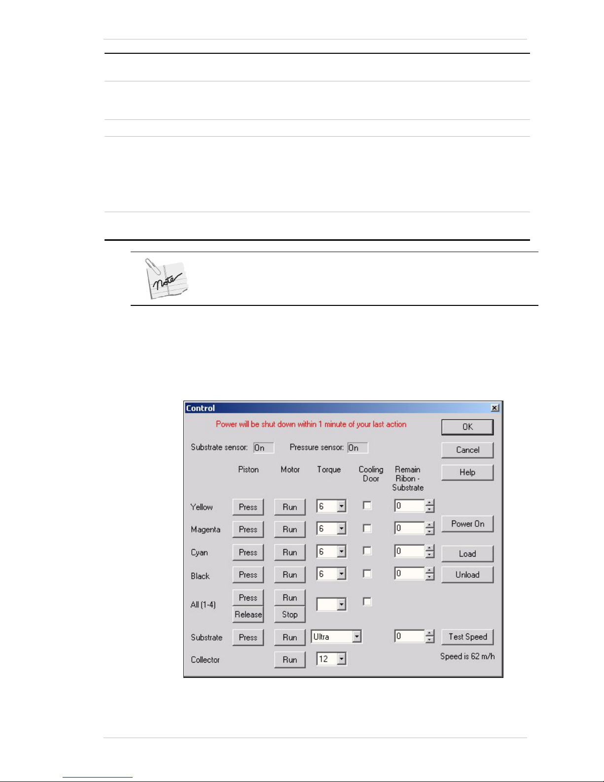
Around the Windows The Utilities Menu
Sprinter User's Manual 6-13
Group Box Screen
Component
Description
Substrate
sensor
Check this option to activate the Substrate Sensor.
This option should not be checked if you are using a
transparent Substrate.
Run collector Check this option to run the Collector motor during printing.
Printing Energy The energy with which the Print Head prints the color on the
Substrate.
Select the Energy Level from the Drop-down list.
Factory recommended energy levels are:
4 – 8 for paper (dye sublimation), 18 – 24 for vinyl (resin), and
25 – 30 for banners (resin).
Ribbon type The type of Ribbon used – determined by the printing energy
level selected from the Printing energy drop-down list.
The Printing Head settings need only be set once for each substrate.
Once they are set, they will automatically be used when that particular substrate
is specified.
The Control Dialog Box
You access CONTROL DIALOG BOX by clicking CONTROL PANEL MENU from the
U
TILITIES menu or by clicking CONTROL in the MAIN SCREEN. You control
most of printing operations from this dialog box.
Figure 6-9: The Control Dialog Box
Page 54
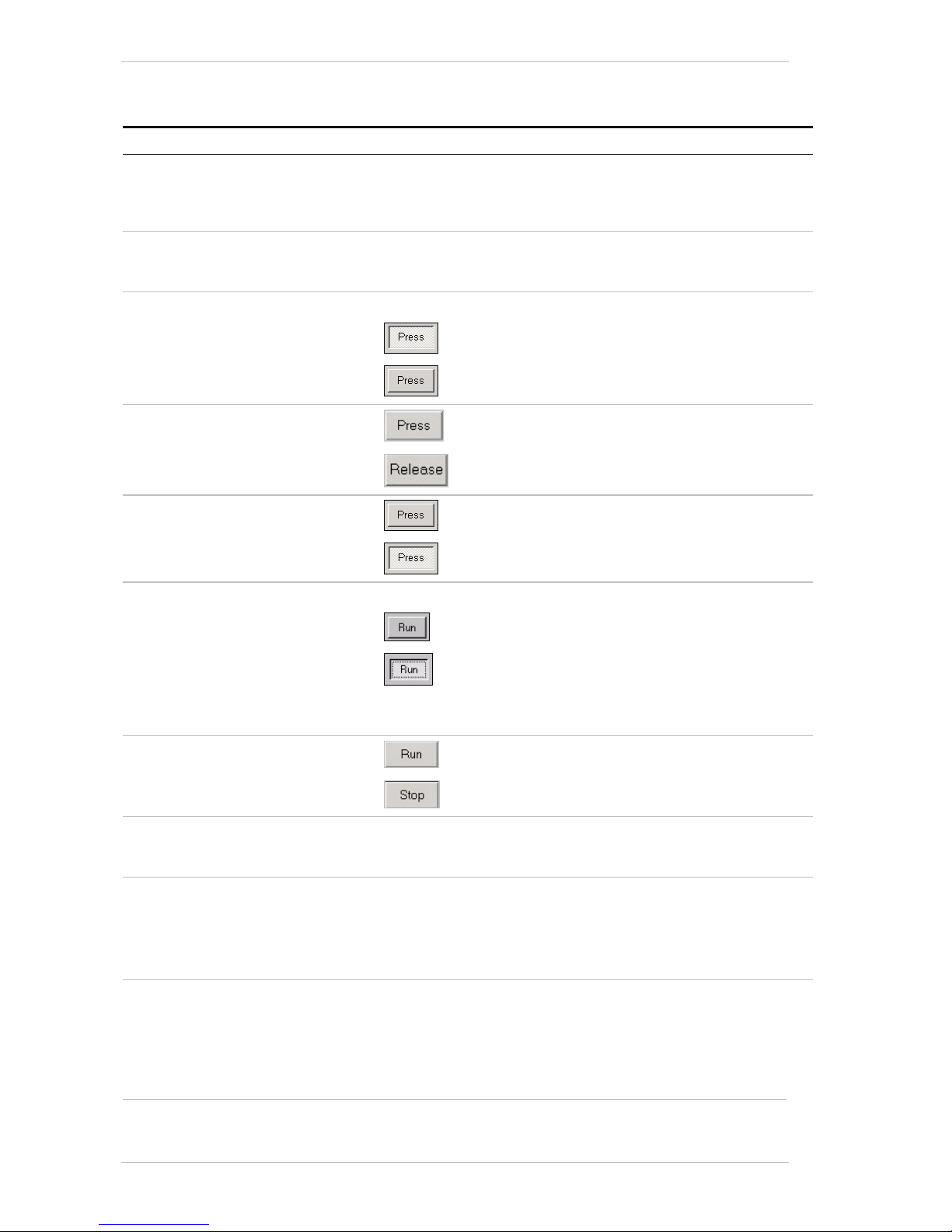
The Utilities Menu Around the Windows
6-14 Sprinter User's Manual
The list below sets out all the settings you can make and describes the
various parts’ status you can read through the C
ONTROL PANEL dialog box.
Setting/Status Description
Substrate Sensor Indicates the status of the Substrate Sensor, as set in the
Configuration dialog box.
When there is no substrate present, an appropriate message
appears.
Pressure Sensor Indicates the status of the Pressure Sensor, as set in the
Preference dialog box.
When there is no pressure, an appropriate message appears.
Yellow/Magenta/Cyan/Black
Piston DOWN
To Raise and lower the relative color’s Piston.
…indicates that the head piston is up.
…indicates that the head piston is down.
All (1-4)
Click Press to raise all the Print Head Pistons.
Click Release to lower all the Print Head Pistons.
Substrate
…indicates that the Substrate Piston is up.
…indicates that the Substrate Piston is down.
Yellow/Magenta/Cyan/Black
Motor Run
Operate and stop the relative Ribbon Take-up Motor.
…indicates that the motor is idle.
…indicates that the motor is running.
Select the motor torque from the appropriate drop-down combo
box.
All (1-4)
Click Run to activate all the motors together.
Click Stop to stop all the motors.
Substrate
Run
Run or stop the Substrate Motor.
Select the motor speed from the appropriate drop-down combo
box.
Collector
Run
Run or stop the Collector Motor.
Select the motor torque from the appropriate drop-down combo
box.
The more Substrate on the Collector Roller, the higher the
required torque.
Cooling Door These option boxes appear only when you have checked the
Cooling System option in the Temperature Control group box
of the Configuration dialog box.
Check the required option box for continuous operation of the
TCS – without limits. Checking the fifth option box, will cause
the TCS to operate for all the Heads.
Page 55
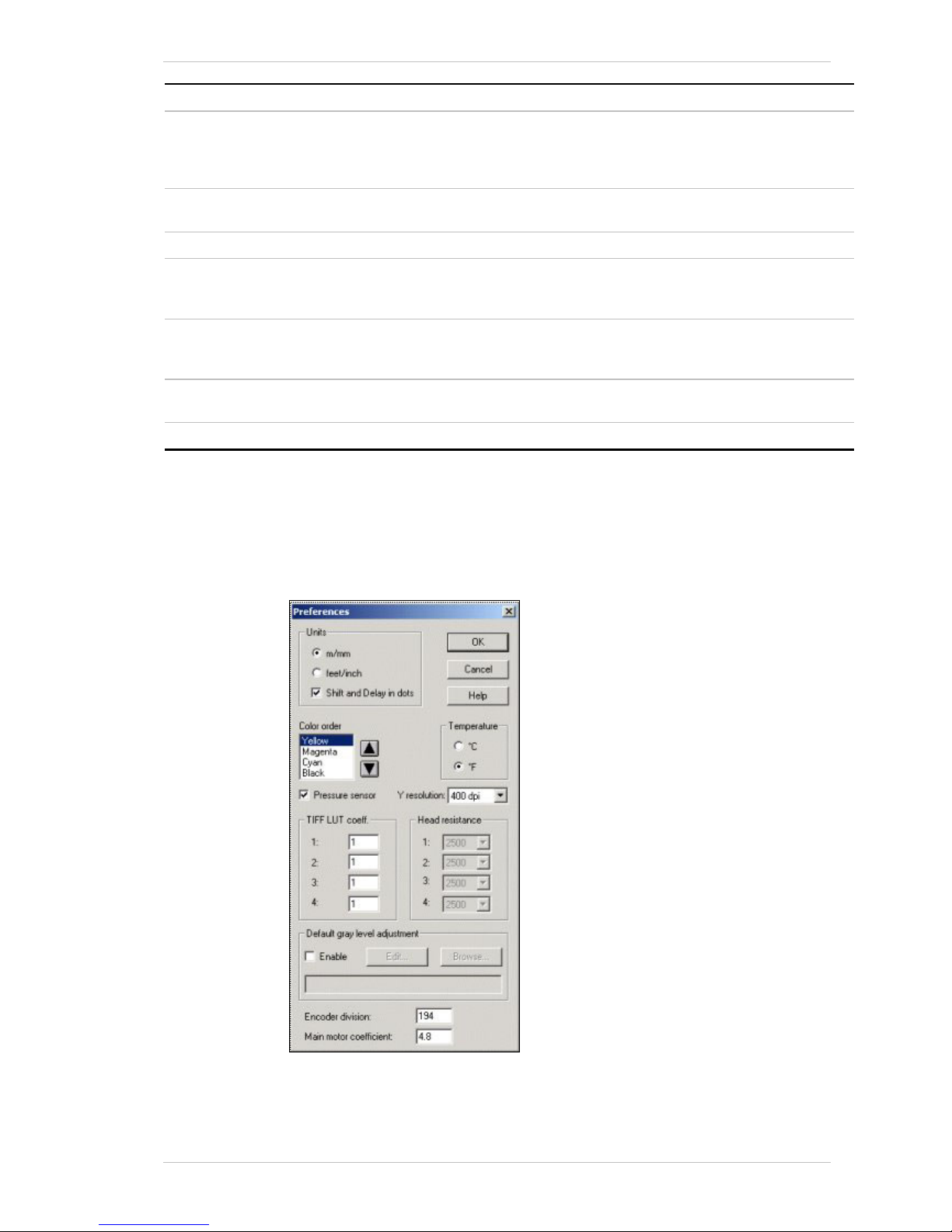
Around the Windows The Utilities Menu
Sprinter User's Manual 6-15
Setting/Status Description
Remain Ribbon – Substrate Enter the amount of Ribbon (per color) and/or Substrate you
have installed. The displayed amounts will reduce during the
printing process and will be reflected in the Printing Window,
during the printing process.
Power On Indicates the power supply status.
With power ON, there is a voltage of 24V.
Load Click to prepare the system for printing.
Unload Click to return the system to rest.
The head piston will be down, the substrate piston will be up.
The 24V voltage is also closed.
Test Speed After selecting the Substrate roller speed, click this button and
the actual roller speed will be displayed as: SPEED IS XX/M.H.
The maximum speed is 60 running meters per hour.
OK Click this button to acccept your settings and close the dialog
box.
Help Click this button to access the online Help.
The Preferences Dialog Box
You access the PREFERENCES dialog box from the UTILITIES menu or by
clicking P
REFS in the MAIN SCREEN. You set the printing preferences from
this dialog box.
Figure 6-10: The Preferences dialog box
Page 56

The Utilities Menu Around the Windows
6-16 Sprinter User's Manual
Group Box Screen
Component
Description
Units M/mm
feet/inch
Shift and Delay
in dots
Units of measure
Color Order Choice of the printing color order, according to the order in
which the Ribbons are installed on the printer.
Temparature °C
°F
Units of measure – temperature
TIFF LUT coeff: Enables you to adjust the density percentage of each color
station.
For example, entering 0.9 on the 1
st
color station, will decrease
that color’s density by 10%. Conversely, entering 1.1 on the 1
st
color station, will increase that color’s density by 10%.
Head
Resistance
Not yet implemented.
Grey level
adjustment
Enable Check this option to enable the grey level adjustment feature.
For all 50 dpi TIFF files that are to be printed.
Edit Click this button to access the Grey Level dialog box.
Browse Click this button to browse for an existing Grey Level file.
General Pressure sensor When activated, if there is a change of air pressure greater
than ± 0.5Bar, an error message appears, informing you of the
status.
We recommend you to keep this feature activated. If however,
the fault will take time to correct, and you can safely continue
working until then, you can deactivate this option on a
temporary basis.
Y resolution 400 x 200 dpi resolution only, implemented.
Encoder
Division
Related to the main pulling system.
See the Note at the end of this table.
Main motor
coefficient
Related to the main pulling system.
See the Note at the end of this table.
OK Click this button to acccept your settings and close the dialog
box.
Cancel Click this button to close the dialog box without saving your
settings.
Help Click this button to access the online Help.
The Encoder Division and Main Motor Coefficient parameters must be checked
immediately after the software installation. This is done through the Preferences
dialog box (see the Setting the Preferences section).
Page 57
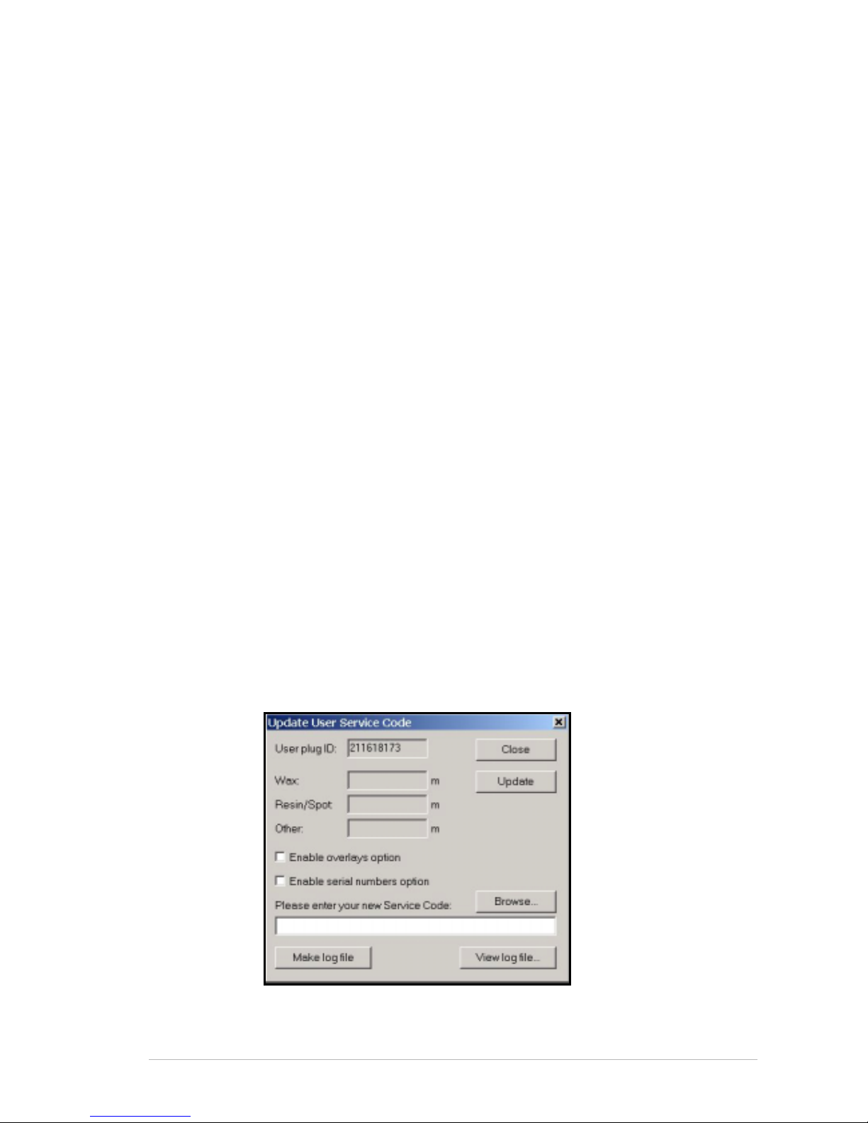
Sprinter User's Manual 7-1
7 Updating the Software and User Service
Code
This chapter descr ibes the procedure for updati ng your User Service Code
The User Plug
The USER PLUG is connected to the parallel port of the PC. It contains the
following information about your printer and R
IBBONS:
• The printer type
• The User Plug ID
• Amount of R
IBBONS (adjusted when you update the USER
SERVICE CODE and when you print).
• Overlays option
• Serial Number option
The User Service Code
Each time you purchase additional RIBBONS from the dealer or directly
from Matan, you will receive a new U
SER SERVICE CODE (in text format -
*.txt,) that has to be copied (or selected after browsing and copied,) into the
printer's PC through the U
PDATE USER SERVICE CODE dialog box (in the
Sprinter’s software)(Figure 7-1).
(You will then have usage permission for the total length of each type of
ribbon that you purchased (including any unused length already recorded
on the PC).
Each printer has its own U
SER PLUG ID. This number appears in the
U
PDATE USER SERVICE CODE dialog box.
The E
NABLE OVERLAYS and ENABLE SERIAL NUMBERS OPTION features will be
automatically checked after the S
ERVICE CODE is updated, if you have
purchased this optional feature.
Figure 7-1: The Update User Service dialog box
Page 58
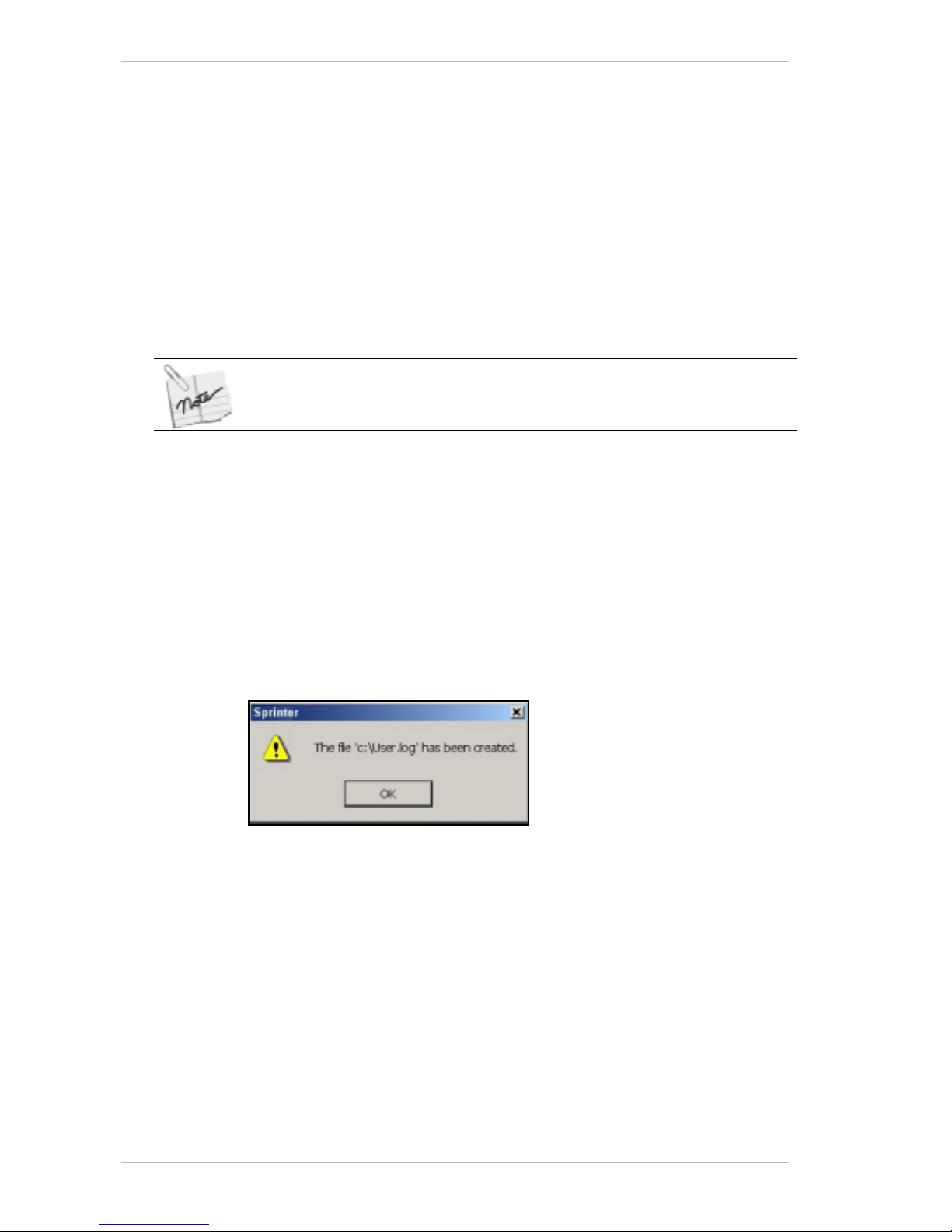
Creating Log Files Updating the Software and User Service Code
7-2 Sprinter User's Manual
! To update the User Service Code:
1. From the U
TILITIES drop-down menu, select UPDATE SERVICE CODE. The
U
PDATE USER SERVICE CODE dialog box appears (Figure 7-1, page 7-1).
2. In the P
LEASE ENTER YOUR NEW SERVICE CODE field, paste or browse and
select, the user's code (provided by the dealer or Matan,) and click
U
PDATE.
The users' ribbon usage permission is updated with the total length of
each type of R
IBBON that they purchased with this code. The total
length of ribbon usage permission that you now have (including the
amount that might have remained from before the current update),
appears in the M
ETERS/FEET field of the dialog box. The relative totals
will decrease according to the quantity used during the printing
process.
If you are printing by the YMCK process, the remaining available amount of
Ribbon is the amount appearing in the Meters/Feet field of the Update User
Service dialog box, divided by 4.
Creating Log Files
The LOG file displays the data relating to all RIBBON transactions.
E.g., Updating inventory.
Log files can be created and viewed from the Sprinter applicatio n. They
may be used by Matan for references purposes.
! To create a Log File:
1. In the U
PDATE USER SERVICE CODE dialog box, click MAKE LOG FILE.
The following window opens and displays the location of the U
SER LOG
FILE.
2. Click OK.
Page 59
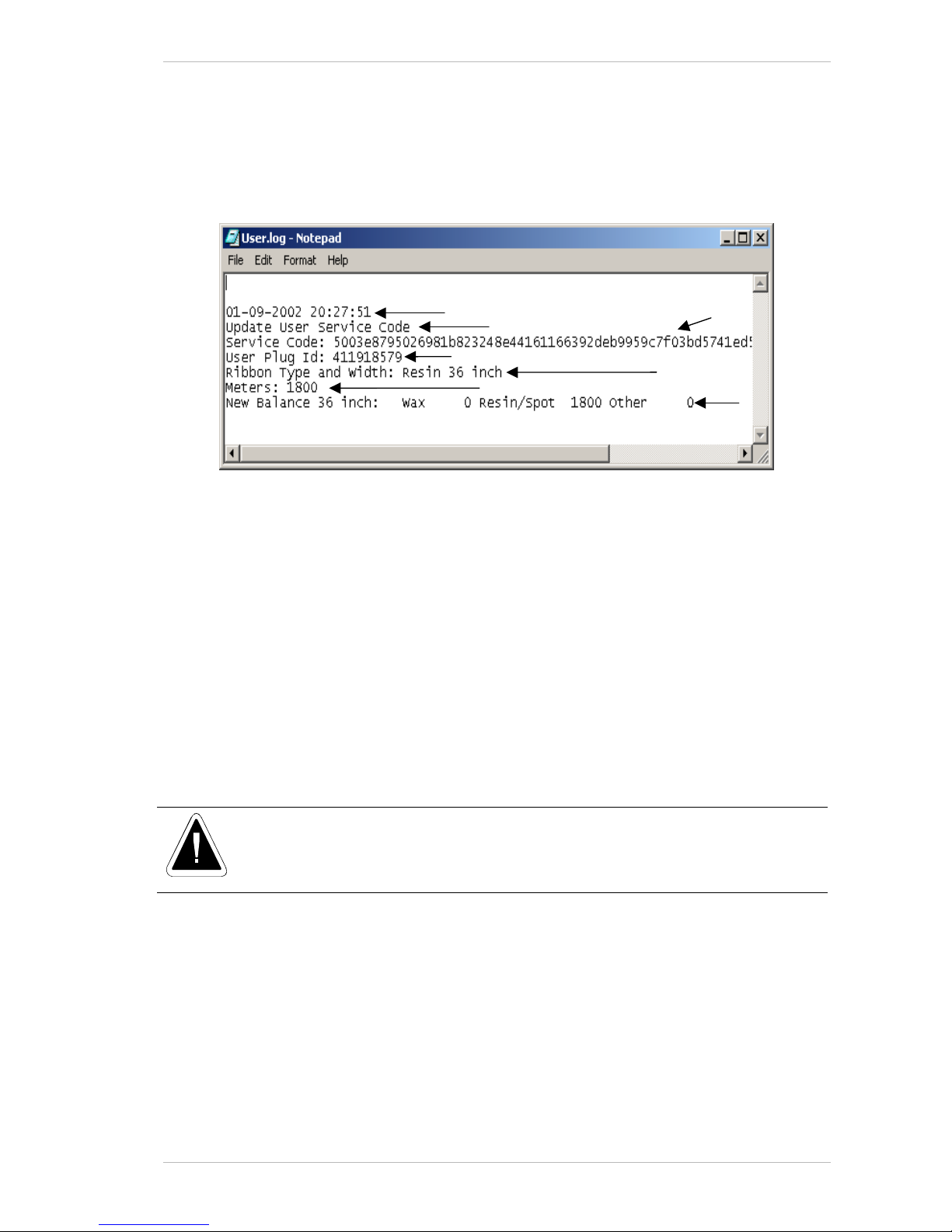
Updating the Software and User Service Code Viewing Log Files
Sprinter User's Manual 7-3
Viewing Log Files
! To view a Log File:
• In the U
PDATE USER SERVICE CODE dialog box, click VIEW LOG FILE.
The L
OG FILE appears (Figure 7-2).
Figure 7-2: A typical User Log File
The LOG FILE contains the following data referred to inFigure 7-2:
• The date and time of the transaction (1).
• Type of transaction
U
PDATE USER SERVICE CODE (When the user buys from the
dealer, or directly from Matan) (2).
• The S
ERVICE CODE (3).
• The U
SER PLUG ID (4).
• The type and width of the ribbon (5).
• The amount of ribbon to be added to the existing stock (6).
• The new balance of ribbons currently licensed to the user's
printer (7).
After each update session, you must make a backup of the log file either on your
network or on a removable medium.
This will avoid the data becoming irretrievably lost if both the plug and the PC
crash.
4
2
3
7
6
1
5
Page 60

Viewing Log Files Updating the Software and User Service Code
7-4 Sprinter User's Manual
This page has been intentionally left blank.
Page 61
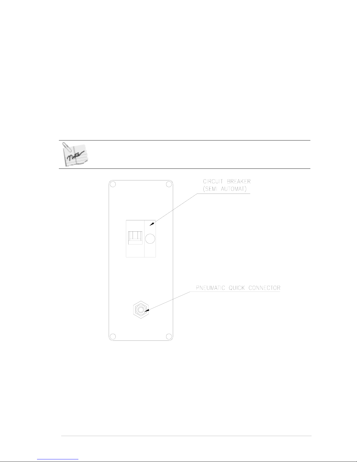
Sprinter User's Manual 8-1
8 Preparing Your Printer for Printing
Preliminary Preparations for Printing
This chapter sets out all the procedures necessary for preparing your
SprinterB Printer for work.
It deals with the setting up of the printer on the mechanical side. It also
sets out a detailed operating procedure for the exchangin g or renewing of
S
UBSTRATES as well as the RIBBONS.
Once you have completed the following procedures, your SprinterB Printer
will be ready to use.
The Operating Procedures as set out in this manual should be followed in the
order that they are presented.
Figure 8-1: The Power Socket and Air Inlet
! To start up the printer:
1. Check that the air hose is connected.
2. Check that you have 4 Bar of air pressure on the A
IR PRESSURE GAUGE
for the 36” printer and 4.5 Bar for the 40” model.
3. Check that you have 220 VAC electric supply from the cable connected
to your power source.
Page 62
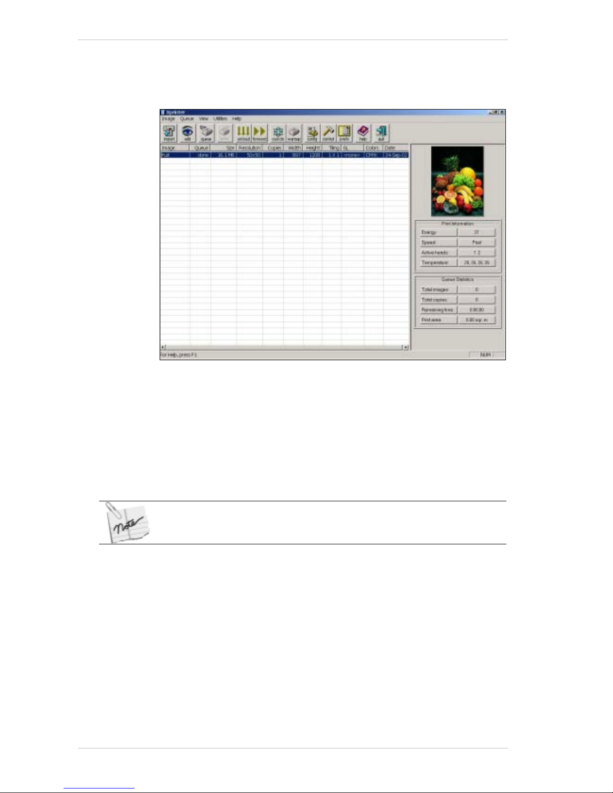
Preliminary Preparations for Printing Preparing Your Printer for Printing
8-2 Sprinter User's Manual
4. Ensure that the main electric switch is ON, and CIRCUIT BREAKER’S
button is pressed.
5. Ensure that the main electric switch is ON, and C
IRCUIT BREAKER’S
button is pressed.
Figure 8-2: The Main Screen
6. Switch on the Computer and invoke the program by double-clicking the
SprinterB icon.
The M
AIN SCREEN appears (Figure 8-2).
Make sure that the green lights on all H
EAD CARDS are lit. The HEAD
CARDS are located on top of the COOLING CHANNEL illustrated in
Figure 8-3, page 8-3, under which the P
RINT HEAD is located. If it is not
on, refer to the appendix on Troubleshooting at the end of this manual.
When the 24v power supply is activated, the yellow light on the Print Head
Card is lit.
Page 63
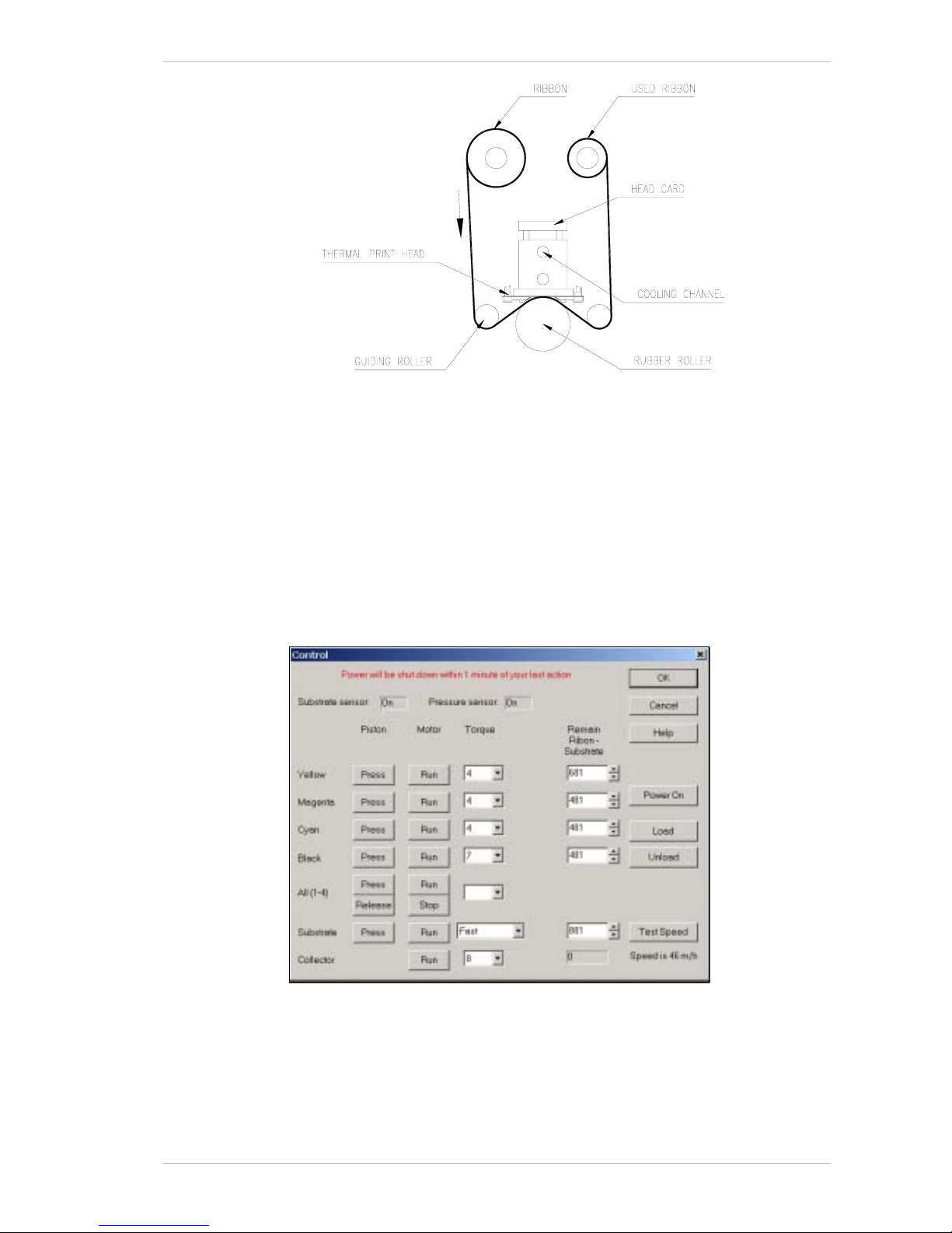
Preparing Your Printer for Printing Preliminary Preparations for Printing
Sprinter User's Manual 8-3
Figure 8-3: The Cooling Channel and Thermal Print Head
Loading or Replacing a Substrate Roll
Your Sprinter printer has been supplied with the SUBSTRATE installed, but
not loaded onto the T
AKE-UP CORE. Our technician will load it for you.
To install a new S
UBSTRATE ROLL or replace an existi ng one, carry out the
following procedures.
You can either replace the S
UBSTRATE ROLL before it is completely used or
when the S
UBSTRATE CORE is empty.
Figure 8-4: The Control Panel Dialog Box
Page 64
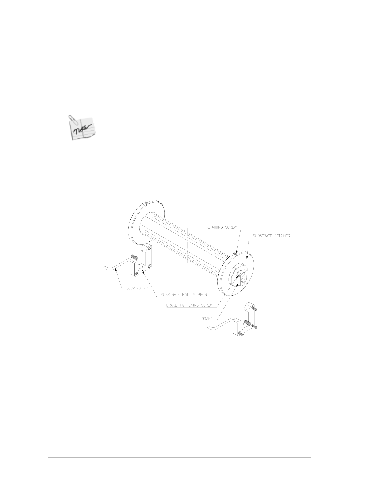
Preliminary Preparations for Printing Preparing Your Printer for Printing
8-4 Sprinter User's Manual
! To Load the Substrate Roll:
1. From the M
AIN SCREEN, click CONTROL.
The C
ONTROL PANEL dialog box appears (Figure 8-4, page 8-3).
- or From the U
TILITIES menu, select CONTROL PANEL.
The C
ONTROL PANEL dialog box appears.
2. Click U
NLOAD to lower all pistons and raise the PULLING ROLLER.
If the Ink Pistons are correctly positioned, their corresponding buttons in the
Control Panel will indicate ‘Down’ with a dotted frame around the word.
3. Take out the
STICKY CLEANING RUBBER ROLLER (the DUST COLLECTOR) by
pushing it left and pulling it out.
4. Wash it under the water tap, let it dry for a few minutes and relocate it.
5. Remove the L
OCKING PIN from both the SUBSTRATE ROLL SUPPORTS
(Figure 8-5).
Figure 8-5: The Substrate Roll Assembly
6. Lift and remove the SUBSTRATE ROLL from the SUBSTRATE ROLL SUPPORTS
and place it on a clean, flat surface.
7. Loosen the two R
ETAINING SCREWS and remove the right hand SUBSTRATE
RETAINER from the roll.
8. Remove the empty core and replace it with a new S
UBSTRATE ROLL.
Ensure that the new S
UBSTRATE ROLL is located in the middle of the BAR
that holds it.
9. Relocate the S
UBSTRATE RETAINER and tighten the two RETAINING
SCREWS.
10. Hold the S
UBSTRATE ROLL with the SUBSTRATE edge towards the printer.
Page 65
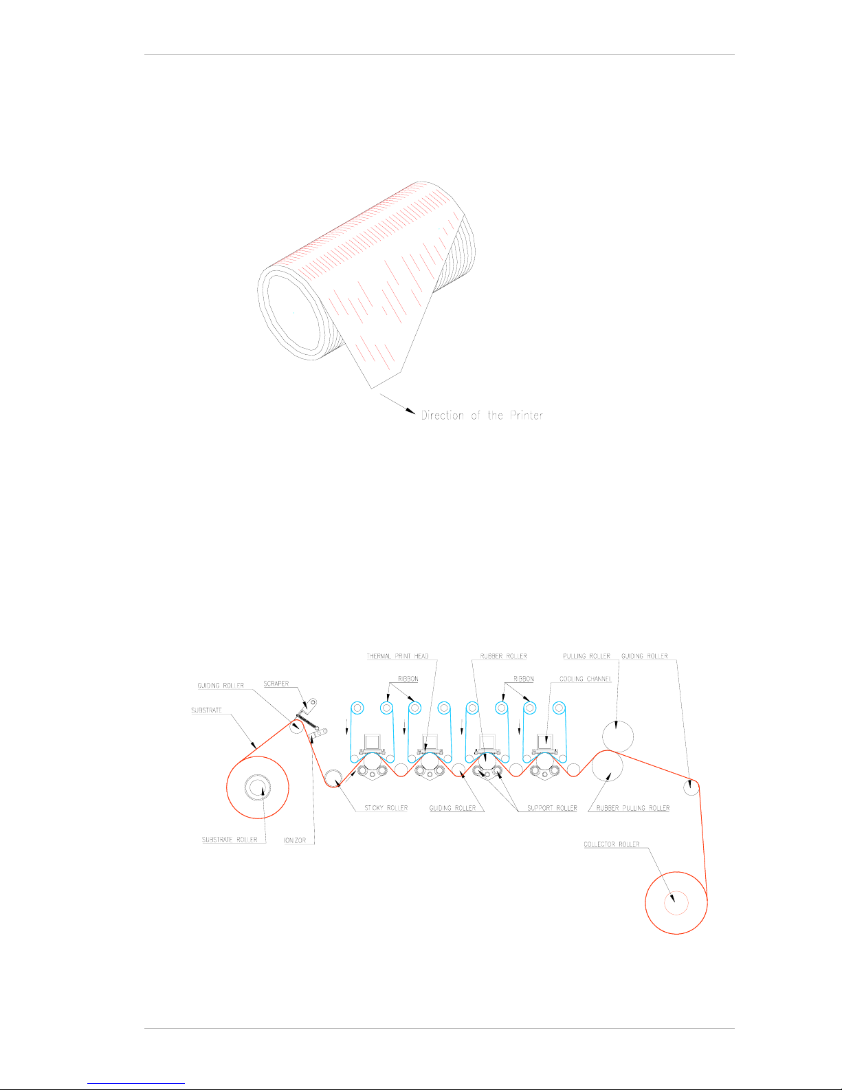
Preparing Your Printer for Printing Preliminary Preparations for Printing
Sprinter User's Manual 8-5
11. With the split in the BRAKE located at each end of the holders fac ing
upward, place the S
UBSTRATE ROLL back into SUBSTRATE ROLL SUPPORTS.
12. Relocate the L
OCKING PINS.
13. Cut off the first meter of the roll to prevent dirt from reaching the P
RINT
HEADS, Then cut a diagonal piece as illustrated in Figure 8-6.
Figure 8-6: Substrate Roll
14. Feed more than a meter of the SUBSTRATE between the SUBSTRATE
GUIDING ROLLER and the sprung SCRAPER, under the IONIZOR, and then
under the S
TICKY ROLLER.
15. Thread the substrate toward the front of the printer, on top of the
rubber rollers and under the G
UIDING ROLLERS, as illustrated in
Figure 8-7. Ensure that the S
UBSTRATE is placed within the limits of the
ribbons’ width and is not protruding over the edges on eit h er s i de, m or e
than 915mm.
Figure 8-7: The Substrate and Ribbon Path
Page 66
Preliminary Preparations for Printing Preparing Your Printer for Printing
8-6 Sprinter User's Manual
The Anti-static Brush and Strip that are located next to each Print Head, are
not shown in Figure 8-7, page 8-5.
16. When you reach the front en d, pull the S
UBSTRATE until the entire width
has reached the front.
17. Close all the covers.
To replace the S
UBSTRATE, see the following procedures:
If possible, you should always try to leave an amount of Substrate under the
Print Heads so as to facilitate easy replacement or renewal.
! To replace the Substrate:
1. From the M
AIN SCREEN, click CONTROL.
The C
ONTROL PANEL dialog box appears (Figure 8-2, page 8-2).
- or From the U
TILITIES menu, select CONTROL PANEL.
The C
ONTROL PANEL dialog box appears.
2. Click U
NLOAD to lower all pistons and raise the PULLING ROLLER.
If the Ink Pistons are correctly positioned, their corresponding buttons in the
Control Panel will indicate ‘Down’ with a dotted frame around the word.
3. Take out the
STICKY CLEANING RUBBER ROLLER (the DUST COLLECTOR) by
pushing it left and pulling it out.
4. Wash it under the water tap, let it dry for a few minutes and relocate it.
5. Cut the old S
UBSTRATE as near as possible to the roll.
6. Remove the L
OCKING PIN from both the SUBSTRATE ROLL SUPPORTS.
(Figure 8-5, page 8-4).
7. Lift and remove the S
UBSTRATE ROLL from the SUBSTRATE ROLL SUPPORTS
and place it on a clean, flat surface.
8. Loosen the two R
ETAINING SCREWS and remove the right hand SUBSTRATE
RETAINER from the roll.
9. Remove the empty core and replace it with a new S
UBSTRATE ROLL.
Ensure that the new S
UBSTRATE ROLL is located in the middle of the BAR
that holds it.
10. Relocate the S
UBSTRATE RETAINER and tighten the two RETAINING
SCREWS.
11. Hold the S
UBSTRATE ROLL with the SUBSTRATE edge towards the printer.
12. With the split in the B
RAKE located at each end of the holders facing
upward, place the S
UBSTRATE ROLL back into SUBSTRATE ROLL SUPPORTS.
Page 67
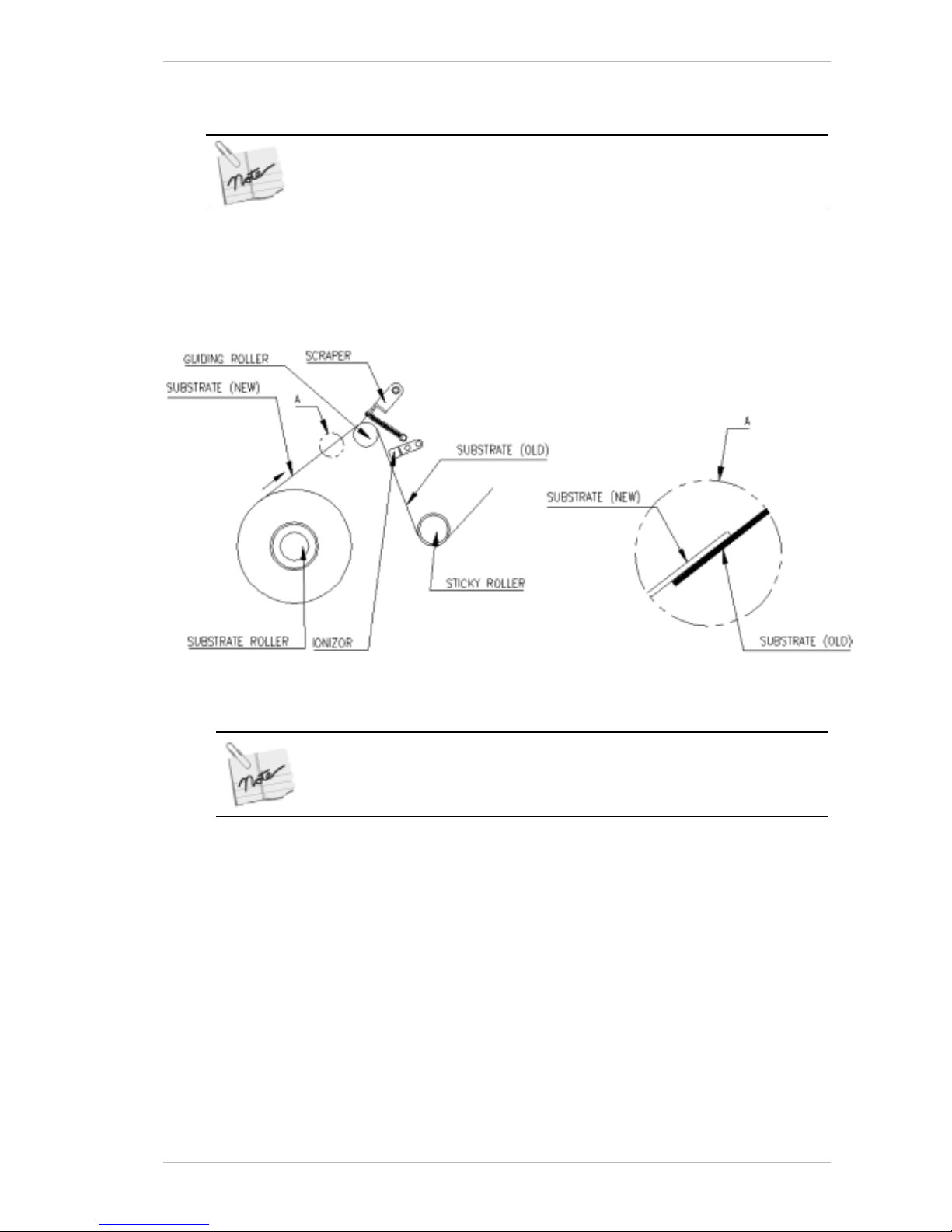
Preparing Your Printer for Printing Preliminary Preparations for Printing
Sprinter User's Manual 8-7
13. Relocate the LOCKING PINS.
If you constantly use the same width substrates, you may remove only the
right hand cone every time.
14 Cut off the first meter of the roll to prevent dirt from reaching the P
RINT
HEADS.
15. Join the new or replaced S
UBSTRATE to the existing piece under the
P
RINT HEADS by using adhesive tape (Figure 8-8).
Figure 8-8: Joining the New substrate to the Existing Piece
The preferred method is to ensure that the new Substrate is placed on
top of the old Substrate. (See Figure 8-8)
16. Lift the S
CRAPER until the join has passed under it.
17. From the M
AIN SCREEN, click FORWARD.
The S
UBSTRATE advances. When the new or replacement SUBSTRATE has
been passed over all four R
OLLER ASSEMBLIES, and the SUBSTRATE
PULLING ROLLER click STOP, in the window that appears.
It should now be resting over the S
UBSTRATE PULLING CYLINDER and
under the P
RESSING ARM.
Leave approximately 50 cms of new or replacement S
UBSTRATE free, or
attach it to the C
OLLECTOR.
18. Close the S
UBSTRATE ROLL COVER.
Page 68
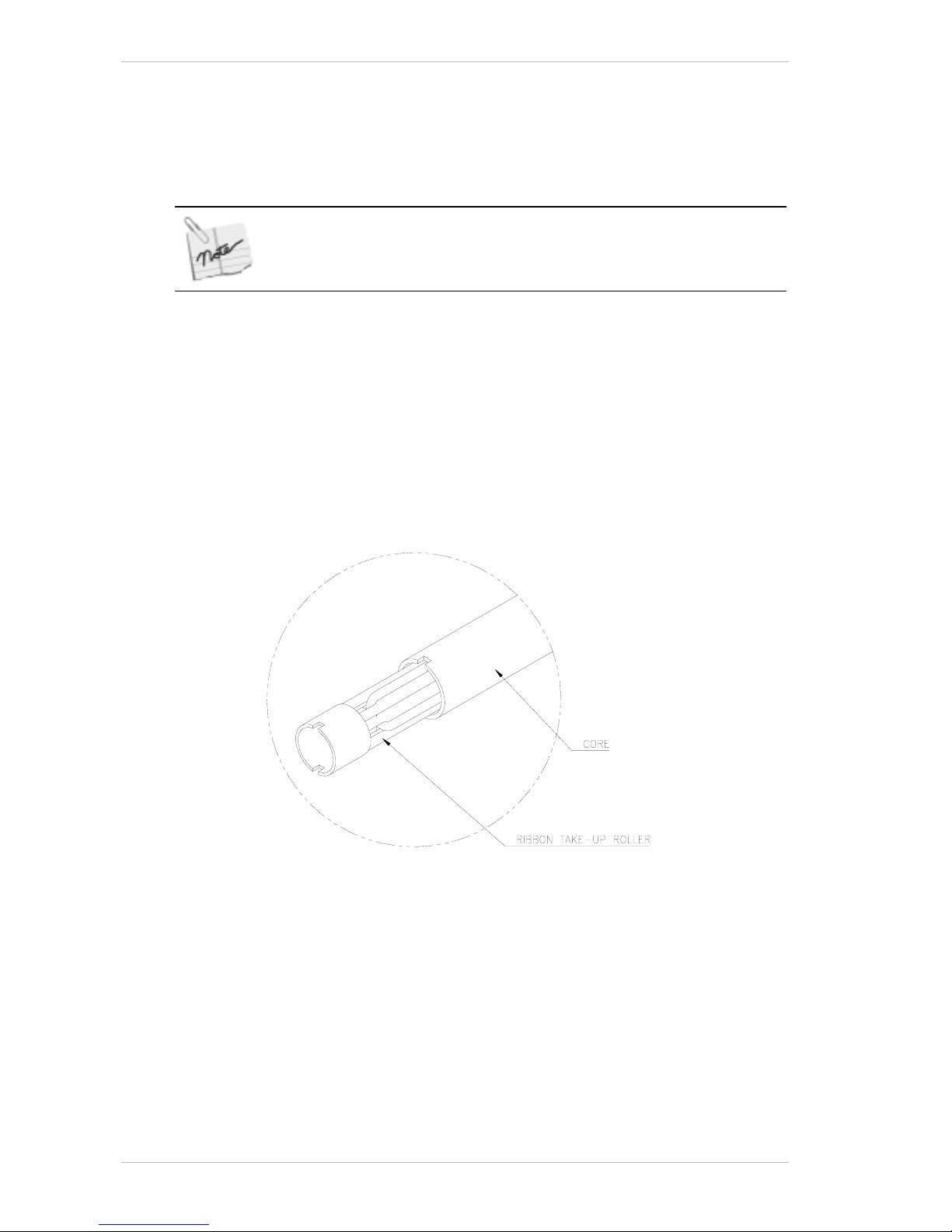
Preliminary Preparations for Printing Preparing Your Printer for Printing
8-8 Sprinter User's Manual
Replacing the Used Ribbons
The following pr oc edure has to be followed when replacing the RIBBON with
another one, or renewing a used one.
The take-up core should not be overloaded at any time.
If the volume of used Ribbon on the Take-up Core exceeds half the
volume of the new Ribbon, you should empty the used Ribbon.
! To replace a Ribbon:
1. From the C
ONTROL PANEL dialog box, click UNLOAD SUBSTRATE.
The printer will come to rest.
2. Open the T
OP COVER.
3. Tear off the R
IBBON on the take-up core side, close to the core.
4. Roll the excess R
IBBON back on to the roll that you are about to change.
5. Take out the R
IBBON that needs to be changed, by pushing it to the
side, and then pulling it out.
6. Remove the T
AKE-UP ROLLER.
Figure 8-9: Cleaning the take-up Roller from the used Ribbon
7. Remove the used RIBBON from the TAKE-UP ROLLER by pulling off the
R
IBBON ROLL.
8. Install an empty core on the T
AKE-UP ROLLER and return it to its correct
location (Figure 8-10, page 8-9).
Page 69
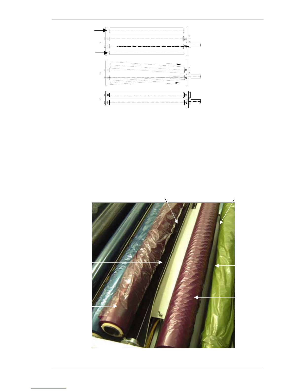
Preparing Your Printer for Printing Preliminary Preparations for Printing
Sprinter User's Manual 8-9
Figure 8-10: Placing the Ribbons into the system
9. Take the new RIBBON and put it in place of the RIBBON you have just
taken out.
10. Pull the R
IBBON underneath the PRINT HEAD – to the outside of the ANTI-
STATIC BRUSH (Figure 8-11).
11. Using adhesive tape, attach the edge of the new R
IBBON to the empty
cardboard roll, at three points.
12. Close the T
OP COVER and from the CONTROL dialog box, click the RUN
button of the relative R
IBBON. Ensure that the RIBBON is fed between
the A
NTI-STATIC STRIP and the TAKE-UP ROLLER.
Figure 8-11: Feeding the Ribbon under the Print Head
New Ribbon
New Ribbon
Anti-static Strip
Anti-static
Brush
Feed the new Ribbon down
and to the outside of the
Anti-static Brush.
Ensure that the New Ribbon is
fed between the Anti-static Strip
and the Take-up Roller.
Unused
Ribbon
Unused Ribbon
(removed from its
correct location,
for clarity)
Page 70

Preliminary Preparations for Printing Preparing Your Printer for Printing
8-10 Sprinter User's Manual
13. From the CONTROL PANEL dialog box, turn the power on and activate the
M
OTOR by clicking the RUN button of the relevant color.
Make sure that the R
IBBON is rolling smoothly over the take-up core
through all its width.
14. When the R
IBBON has become taut, stop the MOTOR by clicking the RUN
button.
15. Repeat this procedure with the other three colors as necessary.
16. Close the H
EAD and RIBBON cover.
Page 71
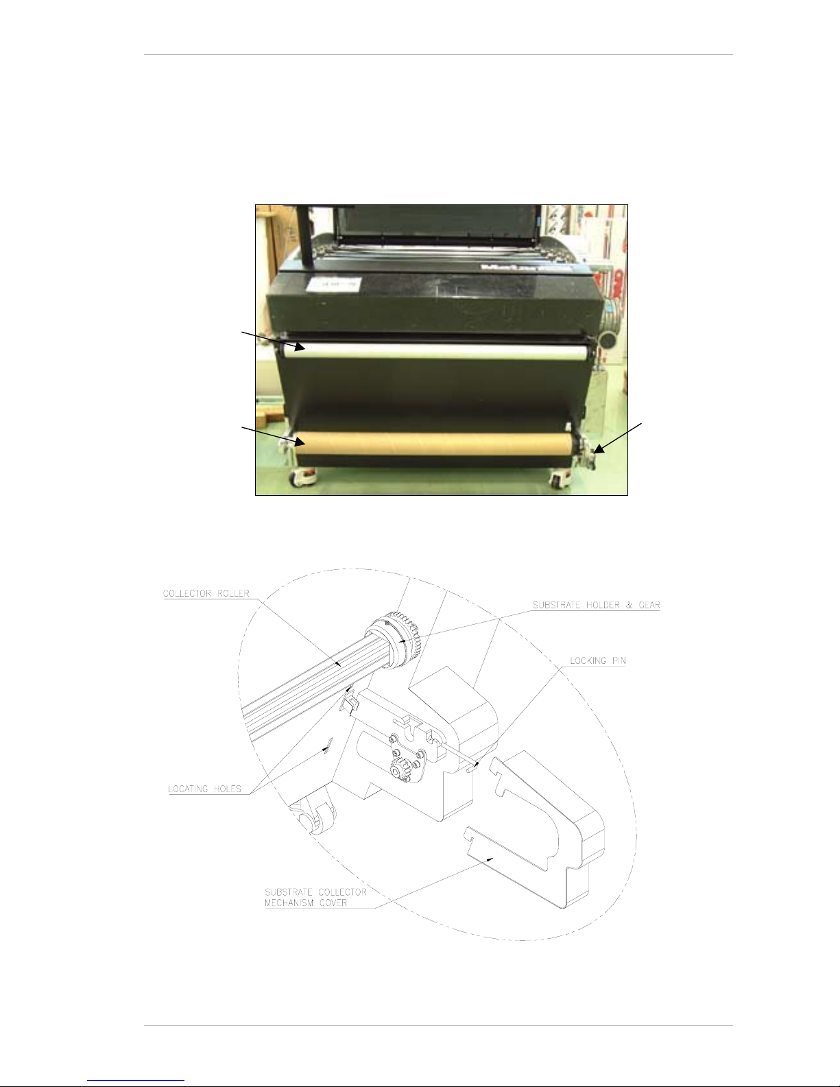
Preparing Your Printer for Printing Operating the Substrate Collecting System
Sprinter User's Manual 8-11
Operating the Substrate Collecting System
The Printer can be operated either with or without the SUBSTRATE
C
OLLECTING SYSTEM operating (Figure 8-12). The COLLECTING MECHANISM
can operate separately from the printer (Figure 8-13).
Figure 8-12: The Substrate Collecting System
Figure 8-13: The Substrate Collecting Mechanism
Substrate
Collecting
Mechanism
Collector
Roller
Guiding
Roller
Page 72
Operating the Substrate Collecting System Preparing Your Printer for Printing
8-12 Sprinter User's Manual
Loading the Printed Substrate into the Collecting System
If you have a long print run, you should load the printed SUBSTRATE onto
the C
OLLECTING SYSTEM.
! To Load the Printed Substrate onto the Collecting System:
1. Engage the C
OLLECTING SYSTEM by checking the RUN COLLECTOR option
in the C
ONFIGURATION dialog box (Figure 8-16, page 8-14).
The C
OLLECTOR ROLLER will rotate during the printing process.
2. Pull out the printed S
UBSTRATE and roll it over the GUIDING ROLLER and
then the C
OLLECTOR ROLLER, as shown in Figure 8-12, page 8-11.
Do not tape the printed Substrate to the Collector Roller as you might wish to
remove it from the core when the roll is full.
Unloading the Printed Substrate from the Collecting System
When the printed roll reaches a diameter of approximately 150mm, the roll
has to be taken out of the C
OLLECTING SYSTEM.
! To unload the Printed Substrate from the Collecting System:
1. Stop the printing process.
2. Cut the printed S
UBSTRATE from the roll.
3. Remove the S
UBSTRATE COLLECTING MECHANISM COVER by lifting it
slightly and then gently pulling it towards you.
4. Pull out both the L
OCKING PINS of the COLLECTOR ROLLER.
Handle the Collector Shaft with care, to avoid damage to the plastic gears.
5. Pull out the printed S
UBSTRATE roll from the COLLECTOR and lay it on a
clean surface.
6. If you do not need to keep the S
UBSTRATE CORE with the printed
Substrate, go to step 10.
7. If you need to keep the S
UBSTRATE CORE with the printed SUBSTRATE,
loosen the Allen screw at the opposite end from the gear wheel and
remove it together with the printed S
UBSTRATE.
8. Replace the S
UBSTRATE CORE with a new one (it must be with a 3"
diameter).
9. Tighten the Allen screw and go to step 13.
10. If you do not wish to remove the S
UBSTRATE CORE, stand the printed
S
UBSTRATE on the floor, with the end opposite the g ea r wheel
downward.
11. Turn the gear wheel end of the C
OLLECTOR ROLLER anti-clockwise until
all the printed Substrate is loose.
12. Pull out the C
OLLECTOR ROLLER.
13. Relocate the C
OLLECTOR ROLLER together with the SUBSTRATE CORE in
the S
UBSTRATE COLLECTOR with the gear wheel to the right.
Page 73
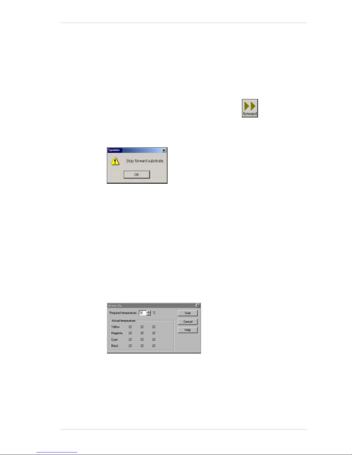
Preparing Your Printer for Printing Software Preparations for Printing
Sprinter User's Manual 8-13
14. Push back both the LOCKING PINS.
15. Relocate the S
UBSTRATE COLLECTING MECHANISM COVER by inserting it
into the two locating holes and gently pulling it downward.
Software Preparations for Printing
Using the Forward Icon
To advance the SUBSTRATE, click the FORWARD icon . This action
brings the printer to the unload status, raises the P
ULLING ARM, runs the
main motor as well as that of the S
UBSTRATE COLLECTOR ROLLER.
When you click the F
ORWARD icon, the following window appears.
To stop the S
UBSTRATE advancing, click OK.
Setting the Print Head Temperatures
During the printing process, the PRINT HEADS’ temperature will naturally
increase. This increase will be controlled by the settings made for the A
IR
COOLING unit (if installed).
Use W
ARM UP before you start a print run. Use COOL DN to reduce THE PRINT
HEAD temperatures to the required level before starting a new print run.
The temperature of the P
RINT HEADS is controlled through the COOL DN and
W
ARM UP icons.
! To warm up the Print Heads to the required temperature:
1. From the M
AIN SCREEN, click WARMUP.
The W
ARM UP. dialog box appears (Figure 8-14).
Figure 8-14: The Warm Up Dialog Box
2. Select the required temperature from the REQUIRED TEMPERATURE spin
box.
3. Activate the C
OOLING SYSTEM.
4. Click S
TART to initiate the process.
Page 74
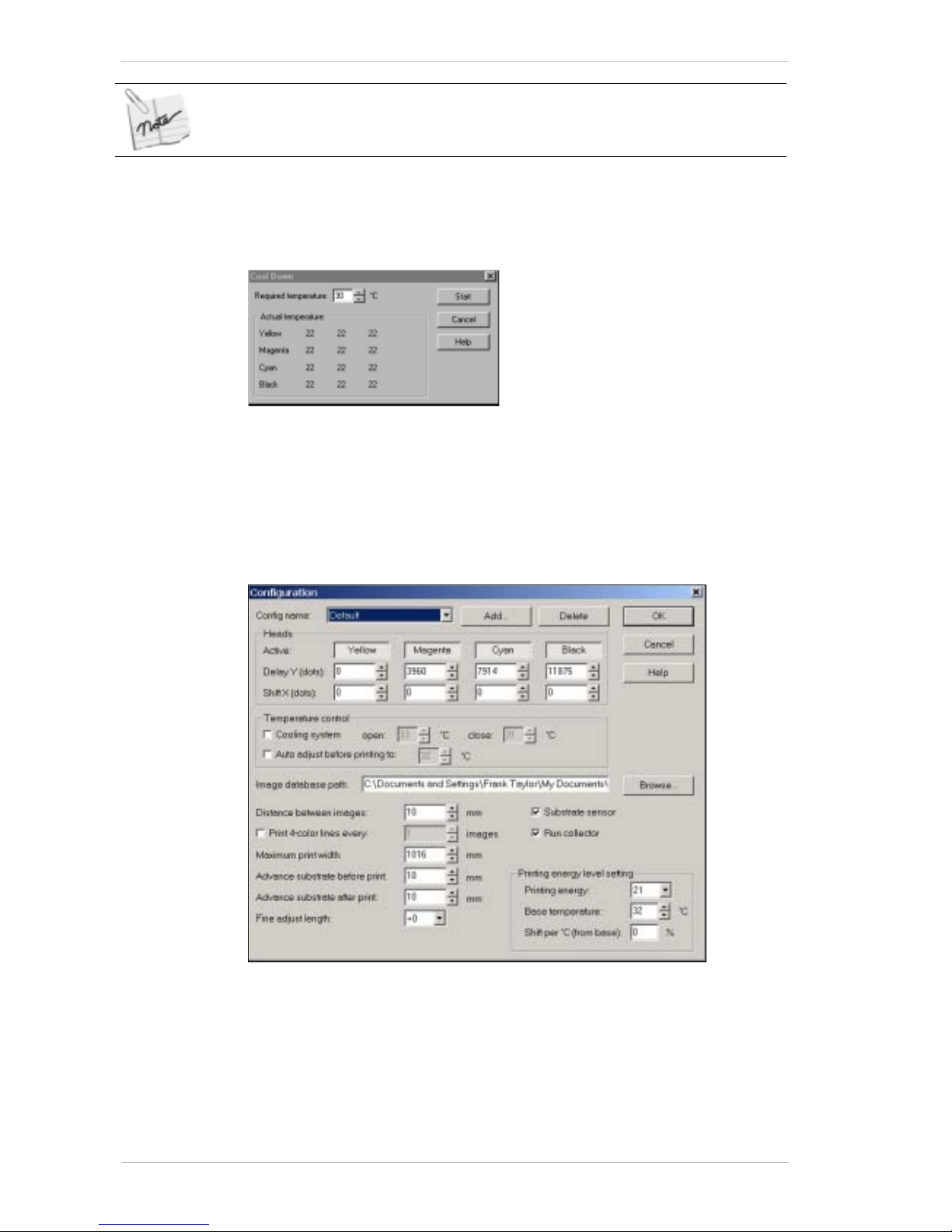
Software Preparations for Printing Preparing Your Printer for Printing
8-14 Sprinter User's Manual
The recommended temperature is 32°C – 35°C.
! To cool down the Print Heads to the required temperature:
1. From the M
AIN SCREEN, click COOL DN.
The
COOL DOWN. dialog box appears (Figure 8-15).
Figure 8-15: The Cool Down Dialog Box
2. Select the required temperature from the REQUIRED TEMPERATURE spin
box.
3. Click S
TART to initiate the process.
Configuring the SprinterB Printer
Figure 8-16: The Configuration Dialog Box
Use the CONFIGURATION dialog box to carry out a comprehensive
configuration of your SprinterB printer.
The various settings for the P
RINTING HEADS are made in this box, as well
as those for speci fying the S
UBSTRATE type, INK type, PRINTING ENERGY.
Various print measurement settings are made in this dialog box as well.
Page 75
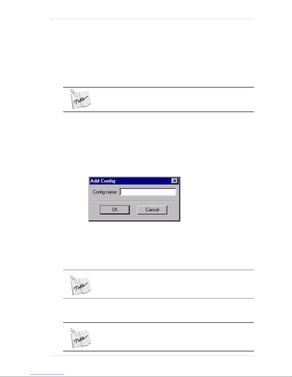
Preparing Your Printer for Printing Software Preparations for Printing
Sprinter User's Manual 8-15
Clicking OK will close the CONFIGURATION dialog box. So you may want to
set all the required configurations before clicking OK.
The procedures have been set out in the order that they appear in the
C
ONFIGURATION dialog box.
Selecting a Different Substrate Type and a Different Set of Head Delays
! To Select a Different Substrate Type and a Different Set of Head
Delays:
The type of S
UBSTRATE determines the HEAD DELAYS.
If you choose ‘No Delay’ in the Substrate box, all heads will start to print at
the same time.
• From the CONFIG drop-down list in the CONFIGURATION dialog box, select
the appropriate S
UBSTRATE.
The corresponding H
EAD settings appear in the HEAD DELAY box within
the C
ONFIGURATION dialog box.
Adding a New Substrate Type
! To Add a New Substrate type:
1. From the
CONFIGURATION dialog box, click Add.
The A
DD CONFIG dialog box appears (Figure 8-17).
Figure 8-17: The Add Config Dialog Box
2. In the CONFIG NAME field, enter the name of the new S UBSTRATE and
click OK.
3. Set the required delays in the corresponding D
ELAY and SHIFT spin
boxes.
When you add a new substrate name, it takes on the same delays as the
previous one.
4. Click OK to exit the dialog box.
If you want to add more than one new Substrate type, save each set of
delays between each addition, by choosing OK in the Configuration window.
The window will close. Open this window again and repeat the above
procedure for each new Substrate.
Page 76
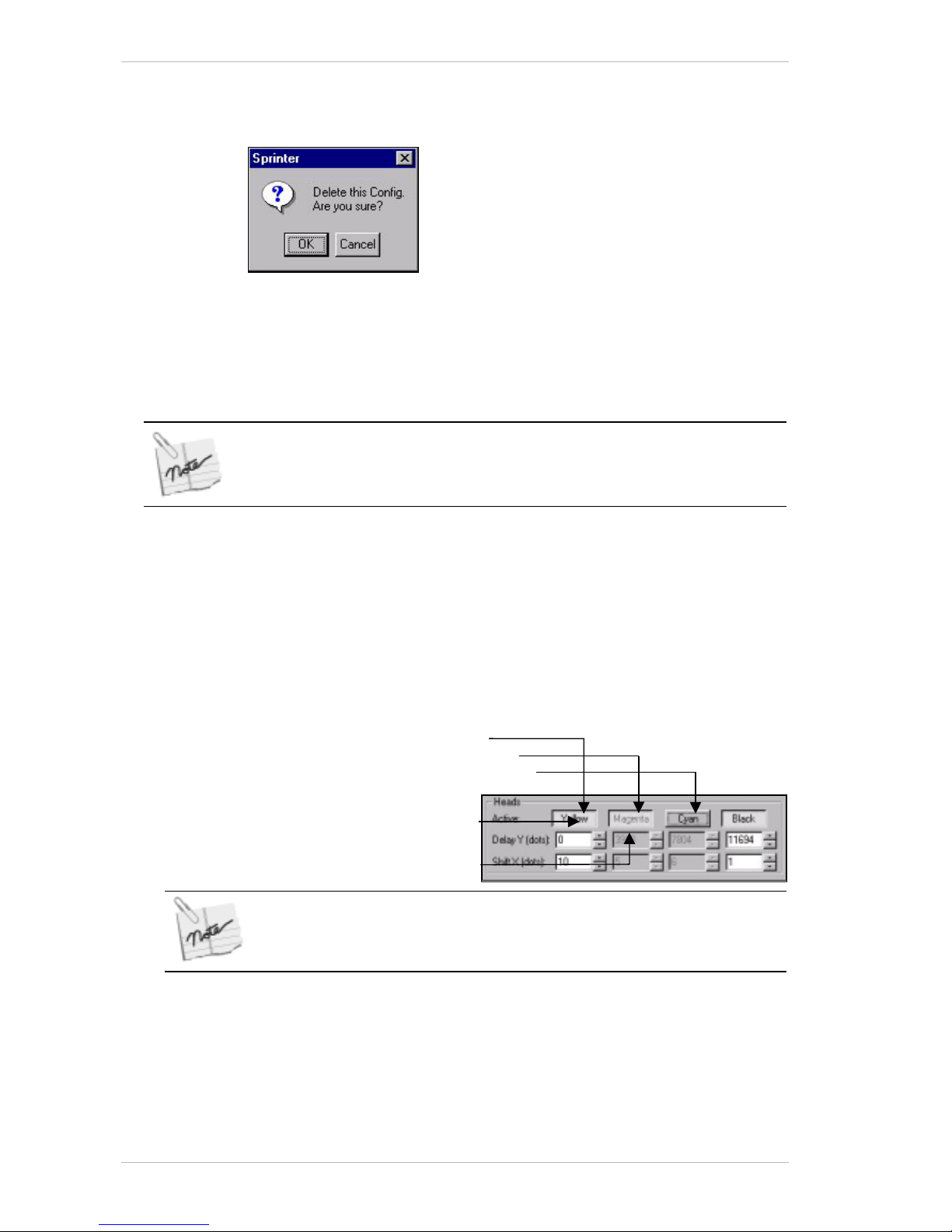
Software Preparations for Printing Preparing Your Printer for Printing
8-16 Sprinter User's Manual
Deleting a Substrate Type
! To Delete a Substrate Type:
Figure 8-18: The Delete Config Window
1. From the CONFIGURATION dialog box, click Delete.
A window opens and prompts you to either confirm deletion or cancel.
(Figure 8-18).
2. Click OK to confirm the delete command.
You cannot delete a factory-set substrate type.
Selecting Active Printing Heads
! To select the Active Printing Heads:
1. From the M
AIN SCREEN, click CONFIG or from the UTILITIES menu, choose
C
ONFIGURATION. The CONFIGURATION dialog box appears (Error!
Reference source not found.).
2. In the H
EADS group box, check the ACTIVE HEAD boxes according to the
colors you wish to use.
Click a color for one of the following settings:
Piston Up and printing
Piston Up and not printing
Piston Down and not printing
If a particular Active Head is not selected, its motor remains inactive and no
data is sent to that head. When loading Substrate, the de-activated station
will not load.
Color name in Black
Color name in Gray
Page 77
Preparing Your Printer for Printing Software Preparations for Printing
Sprinter User's Manual 8-17
Selecting a Head Delay
! To Select a Head Delay:
• From in the H
EADS group box in the CONFIGURATION dialog box, , set
each color’s delay.
The reference is of the distance in dots from each Print Head to the
nearest one. The first Print Head i s therefore always referenced as zero.
For initial reference, the distance between each Print Head is about
4,000 dots. Other units of measure can be selected through the
Preference dialog box.
The new values that you have entered will be used for the present preset
material after closing the screen, by clicking OK.
Setting the Head Shift
! To set the Head Shift:
• From the H
EADS group box in the CONFIGURATION dialog box, set each
color’s Shift. The H
EAD SHIFT determines the point (i.e. the distance
from the first hot dot) where the P
RINT HEAD will start the print.
The first hot dot is the zero point from the right. Each increase in shift
will move the printing to the left.
The H
EAD SHIFT unit of measure is dots. Each HEAD SHIFT unit (dot) is
equal to 0.0635mm* of P
RINT WIDTH. For example, setting the HEAD
SHIFT to 1000, means that the HEAD will start printing 1000 x
0.0635mm (=6.35cms) from its first dot. You should note that the
maximum print width will now be 90-6.35 = 83.6cms. 'H
EAD SHIFT' is
limited to 15.840 (100 Cm).
* A pixel size in 50DPI Tiff, is 0.508mm (8 x 0.0635) exactly on the X-axis.
Page 78

Software Preparations for Printing Preparing Your Printer for Printing
8-18 Sprinter User's Manual
Temperature Control
! To activate the Temperature Control System:
1. In the T
EMPERATURE CONTROL group box of the CONFIGURATION dialog
box, check the C
OOLING SYSTEM option.
2. In the O
PEN and CLOSE drop-down combo boxes, select the required
temperatures.
The O
PEN setting refers to the temperature at which the cooling flaps
are opened and the C
LOSE setting refers to the temperature at which
the cooling flaps are closed. Recommended tempera tures: open at 32°C
and closed at 30°C.
! To activate warm-up before printing starts:
• In the T
EMPERATURE CONTROL group box of the CONFIGURATION dialog
box, check the A
UTO ADJUST BEFORE PRINTING TO: option and select the
required temperature from the drop-down combo box.
Checking this option will cause the Print Heads to be automatically
heated to the specified temerature before printing. Recommended
temperature, between 32 °C and 35°C.
Specifying the path in which the images to be printed are situated
! To specify the path in which the images to be printed are situated:
•In the I
MAGE DATABASE PATH FIELD, enter the relevant path or select it by
using B
ROWSE.
Setting the distance between each printed Image
! To set the distance between each printed Image:
• In the C
ONFIGURATION dialog box, enter or select the required distance
(in millimeters) between each printed image width, from the D
ISTANCE
BETWEEN IMAGES
box.
Setting the 4 colors lines option
! To set the 4 colors lines option:
• In the C
ONFIGURATION dialog box, check the PRINT 4 COLOR LINES EVERY:
option and enter or select the required number.
Checking this option will result in four color lines at 75% strength
being printed, one from each color, across the width of the substrate
after a specified number of images. This helps the operator detect
scratches on the Print Head.
Setting the Print Width
! To set the Print Width:
1. In the C
ONFIGURATION dialog box, enter or select the required width in
millimeters from the M
AXIMUM PRINT WIDTH box.
The P
RINT WIDTH is affected by the HEAD SHIFT parameters. If you try to
set a P
RINT WIDTH that is wider than the total HEAD LENGTH (effective
printing size is 902 mm for the 36” printer and 1016mm for the 40”
printer,) minus the P
RINT SHIFT, the printer will automatically calculate
the maximum available P
RINT WIDTH and following message appears:
Page 79
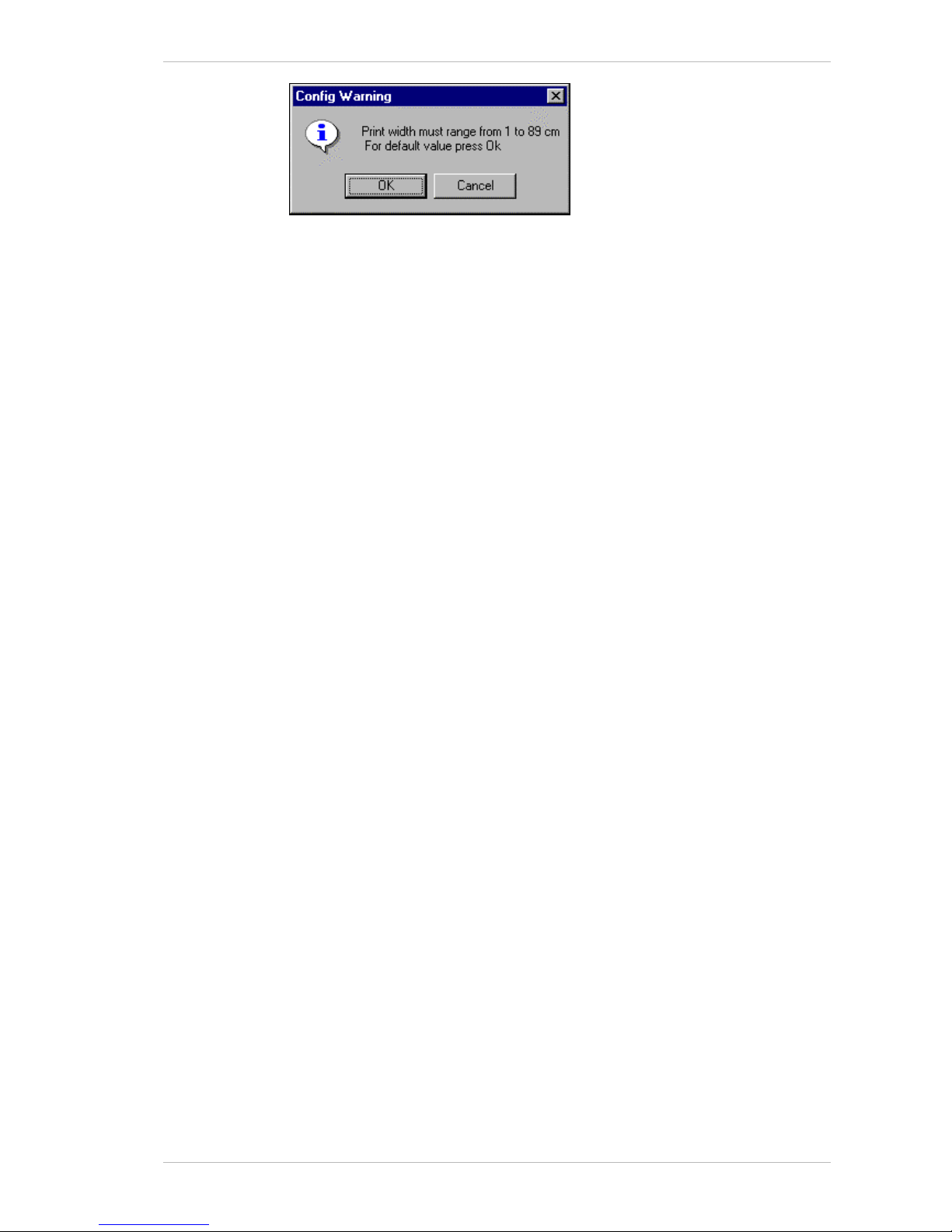
Preparing Your Printer for Printing Software Preparations for Printing
Sprinter User's Manual 8-19
2. Click OK to set the new calculated width.
Advancing the Substrate before printing
Checking this option will cause the substrate to advance a specified
distance before printing commences.
! To advance the substrate before printing:
• In the C
ONFIGURATION dialog box, select the required distance from the
A
DVANCE SUBSTRATE BEFORE PRINT: drop-down combo box.
Advancing the Substrate after printing
Checking this option will cause the substrate to advance a specified
distance after printing ceases.
! To advance the substrate after printing:
• In the C
ONFIGURATION dialog box, select the required distance from the
A
DVANCE SUBSTRATE AFTER PRINT: drop-down combo box.
Adjusting the printed length of the image
There is always the possibility that the printed length of a file might
change when using a more elastic substrate. Generally speaking, you only
have to calibrate the printed length once. However, if you change to a more
elastic substrate such as Banner or Tyvek, you should calibrate the
printed length accordingly.
To calibrate the printed length of a file, print a sample. The file should be
no less than 1.5m long.
You carry out the calibrating procedure by using the F
INE ADJUST LENGTH
option in the C
ONFIGURATION dialog box.
The units displayed in this option's list are media-specific and will have a
different relationship to different media.
Select a positive unit to increase the file length and a negative unit to
decrease it. Each unit is approximately equal to 0.5mm or 0.02".
! To adjust the printed length of the image:
• In the C
ONFIGURATION dialog box, from the FINE ADJUST LENGTH drop-
down combo box, select the required unit of length.
Activating the Substrate Sensor
Checking this option will activate the Substrate sensor. When there is no
substrate present, you will receive a warning.
! To activate the Substrate sensor:
• In the C
ONFIGURATION dialog box, check the SUBSTRATE SENSOR option.
Activating the Run Collector
Checking this option will activate the COLLECTOR MOTOR during printing.
Page 80
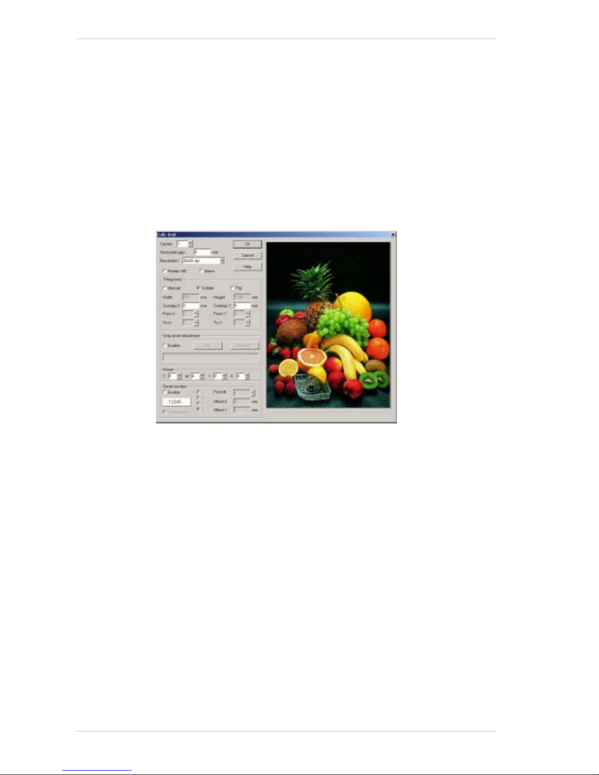
Software Preparations for Printing Preparing Your Printer for Printing
8-20 Sprinter User's Manual
! To activate the Collector Motor:
• In the C
ONFIGURATION dialog box, check the COLLECTOR MOTOR option.
Changing the Energy Level
Setting the ENERGY level determines the intensity of the color to be printed.
! To change the Energy level:
• In the A
DVANCE CONFIGURATION dialog box, from the ENERGY box, select
or enter an E
NERGY level.
Factory recommended energy levels are:
18 – 24 for vinyl , 4 – 8 for paper, and 26 – 31 for banners.
Specifying the Print Settings
Figure 8-19: The Edit Dialog Box
Use the EDIT dialog box to specify the print settings.
You must select the required image in the M
AIN SCREEN before you begin
the editing process.
Clicking OK will close the E
DIT dialog box. So you may want to specify all
the required settings before clicking OK.
The procedures have been set out in the order that they appear in the E
DIT
dialog box.
Specifying the number of copies to be printed
! To specify the number of copies to be printed:
• In the
EDIT dialog box, select the required quantity in the COPIES drop-
down combo box.
Specifying the horizontal gap
If an image is narrow enough to fit in the substrate width more than once,
you can specify the gap between the images. If you have specified a gap
that is wider than the space available, the last image will be printed on the
next row.
Page 81
Preparing Your Printer for Printing Software Preparations for Printing
Sprinter User's Manual 8-21
! To specify the horizontal gap:
• In the
EDIT dialog box, enter the required gap in the HORIZONTAL GAP
field.
Specifying the printing resolution
! To specify the printing resolution:
• In the
EDIT dialog box, select the required resolution (in dpi) in the
RESOLUTION drop-down combo box.
The physical size of the Image will double and its resolution will be reduced by
50%.
Rotating the file to be printed
! To rotate the file:
• In the
EDIT dialog box, check the ROTATE 180° option.
Printing the file as a mirror image
! To print the file as a mirror image:
• In the
EDIT dialog box, check the MIRROR option.
Manually defining the tile size and tile printing order
The Tiling process involves 'cutting a image' (vertically, horizontally or in
both directions,) so that its printed dimensions match those of the
substrate on which it is to be printed or the area where it is ultimately to
be displayed. Tiling would be carried out for either or both of the following
typical reasons:
• The width of an image is greater than that of the
PRINT HEAD.
E.g., an image that is 45" wide and is to be printed with a 36"
PRINT HEAD, for example.
• A image that is 36" wide has to be put into two shop windows
each 18" wide.
! To manually define the tile size and printing order:
1. In the
TILING group box of the EDIT dialog box, check the MANUAL
option.
2. Enter the required printing dimensions.
3. Set the tile overlap in the required
OVERLAP fields.
4. Select the first tile to be printed from either the
FROM X or FROM Y
drop-down combo boxes.
5. Select the last tile to be printed from either the
TO X or TO Y drop-
down combo boxes.
Page 82
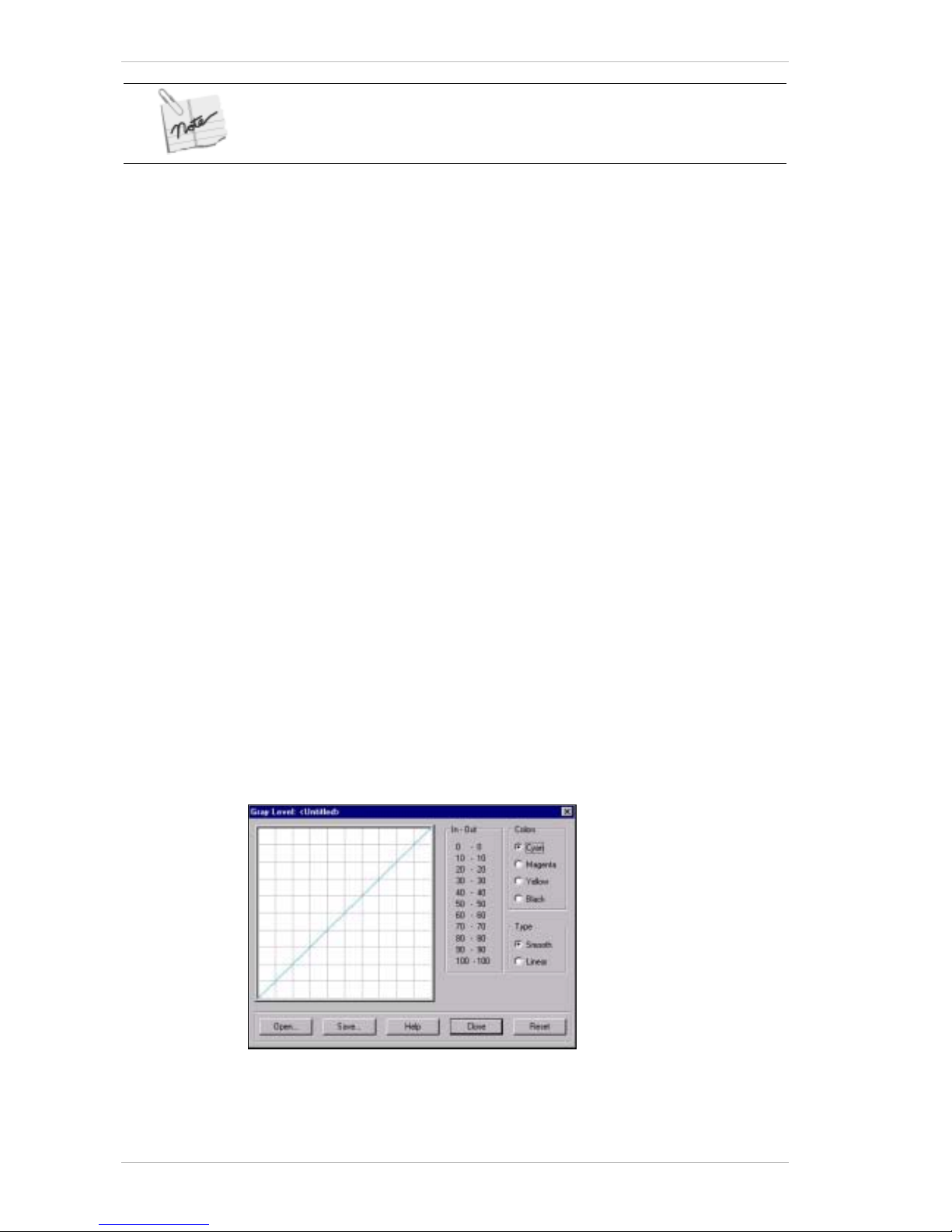
Software Preparations for Printing Preparing Your Printer for Printing
8-22 Sprinter User's Manual
The printer will print an Image in the specificed printing order of its tiles. For each
tiled Image, you must specify its tile printing order.
Collating the printing of two or more copies of a file
When checked, the Collating feature will ensure that when you are printing
two or more copies of the same file, all the tiles in the file are printed in
successive order for each copy.
If the feature is not checked, the first tile of the image will be printed for
each copy, then the second tile, etc., etc.
! To collate the printing:
• In the
EDIT dialog box, check the COLLATE option.
Activating the Flip feature
Although the COOLING SYSTEM prevents any color mismatch between slices,
activating the Flip feature will cause alternate tiles to be rotated 180°. This
will further help to prevent color mismatching.
! To activate the Flip feature:
• In the
EDIT dialog box, check the FLIP option.
Adjusting the Gray Level
The gray level can be adjusted for specific TIFF files. You can also use THE
GRAY LEVEL settings that have been saved previously.
You can adjust the G
RAY LEVEL on all the TIFF files using the PREFERENCES
dialog box (see Figure 8-21, page 8-28).
! To adjust the Gray level of a TIFF file:
1. In the
GRAY LEVEL ADJUSTMENT group box of the EDIT dialog box,
check the
ENABLE option.
2. Click
EDIT.
The
GRAY LEVEL dialog box appears as illustrated below.
3. Choose the color whose G
RAY LEVEL you wish to adjust.
4. Check the Smooth or linear option as required.
5. Pass the cursor over the grid lines and when it is located over the LUT
line, it changes to a cross hair shape.
Page 83
Preparing Your Printer for Printing Software Preparations for Printing
Sprinter User's Manual 8-23
6. Click and drag the line to the required s etting and release the m o us e
button.
7. Repeat steps 3-6 as required.
8. Click Save to save the setting.
The S
AVE AS dialog box appears.
9. Enter a file name and click OK.
10. Close the G
RAY LEVEL dialog box.
11. With the E
DIT dialog box open, click BROWSE and choose the file whose
gray level you wish to adjust.
The file name appears in the G
RAY LEVEL ADJUSTMENT field.
12. Click OK.
The selected file name appears in the GL column of the Main Screen.
Disguising Noise
The NOISE feature is accessible from the EDIT dialog box.
It enables you to disguise any repetitive errors that appear in the printing,
such as those resulting from bending, in 50dpi files only.
For example, if bending has occurred in one or more colors, you should
adjust the N
OISE levels of the relative colors.
The maximum unit value of the Noise adjustment is 30.
If you set the noise level too high, it will result in the image becoming blurred.
Printing a Serial Number
This optional feature enables you to print a serial number on each whole
printed image. The feature works if t he E
NABLE SERIAL NUMBERS OPTION is
checked in the U
PDATE USER SERVICE dialog box.
You cannot print a Serial Number on a sliced image. Nor can you print one on
images that are narrow enough to be printed on the same row.
The
SERIAL NUMBER is printed on the actual image. To avoid this, and to
print it on the
SUBSTRATE, check the TRANSPARENT option. When this
option is checked, the printed matter is erased in the shape of the
SERIAL
NUMBER, which in turn, is printed directly onto the SUBSTRATE.
! To print a Serial Number:
1. In the
SERIAL NUMBER group box of the EDIT dialog box, check the
ENABLE option.
2. Click the
SERIAL NUMBER button (12345…).
The
SERIAL NUMBER FONT dialog box appears.
Page 84
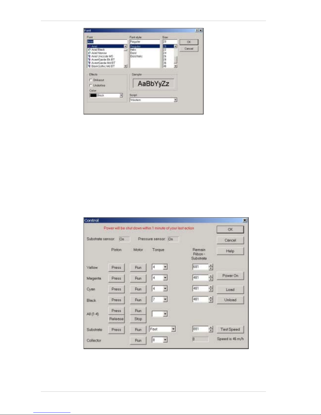
Software Preparations for Printing Preparing Your Printer for Printing
8-24 Sprinter User's Manual
3. Specify the required font format.
4. Click OK.
If required, check t he T
RANSPARENT option (see above).
5. Select the required color(s) of the S
ERIAL NUMBER.
6. From the F
ROM # drop-down combo box, enter or select the number of
the first serial number you want to appear.
7. In the O
FFSET X and OFFSET Y fields, enter the required coeffici ent
location of the S
ERIAL NUMBER.
The S
ERIAL NUMBER’S location is set at the top left-hand corner of the
number.
Setting the Pistons and Motors Parameters
Figure 8-20: The Control Dialog Box
Page 85

Preparing Your Printer for Printing Software Preparations for Printing
Sprinter User's Manual 8-25
There are three wa ys of initiatin g the print proceudre:
• Manually
• By clicking L
OAD in the CONTROL PANEL dialog box and then
clicking P
RINT in the MAIN SCREEN.
• By clicking P
RINT in the MAIN SCREEN.
If you initiate the print procedure manaully, use the C
ONTROL dialog box to
specify the printer’s mechanical settings, such as the Piston and Motor
status.
In order to print, the H
EAD PISTONS must be in the UP position so that the
P
RESSING ROLLERS should press the SUBSTRATE and RIBBON against the
P
RINT HEAD. The SUBSTRATE PISTON must be down.
Clicking OK will close the C
ONTROL dialog box and save the settings.
The following pr ocedures have been set out in th e order that they appear
in the C
ONTROL dialog box.
The Substrate and Ribbon parameters as well as the Gray Level Setting,
must be defined before you give the Print command.
The S
UBSTRATE SENSOR and PRESSURE SENSOR statuses are displayed at the
top of the C
ONTROL dialog box. They are set i n the CONFIGURATION dialog
box.
Raising and lowering a specific piston
! To raise or lower a Color Piston:
• In the C
ONTROL dialog box, click the DOWN button of the relevant color.
to raise the piston and click it again to lower it.
For a specific color status, see the rel ev ant table in the Around the
Windows chapter.
! To raise or lower all the Color Pistons simultaneously:
• In the C
ONTROL dialog box, click the ALL (1-4) UP button to raise all the
color pistons and click the Down button to lower them all.
For the A
LL (1-4) color piston status, see the relevant table in the
Around the Windows chapter.
! To raise or lower the Substrate Piston:
• In the C
ONTROL dialog box, click the DOWN button of the Substrate. to
raise the piston and click it again to lower it.
For a specific color status, see the rel ev ant table in the Around the
Windows chapter.
Running or stopping a specific motor
! To run or stop a Color Motor:
• In the C
ONTROL dialog box, click the RUN button of the relevant motor to
run it and click the same button to stop it.
For a specific color status, see the rel ev ant table in the Around the
Windows chapter.
Page 86

Software Preparations for Printing Preparing Your Printer for Printing
8-26 Sprinter User's Manual
! To run or stop all the Color Motors simultaneously:
• In the C
ONTROL dialog box, click the ALL (1-4) RUN button to run all the
color motors and click the S
TOP button to stop them all.
! To run or stop the Substrate Motor:
• In the C
ONTROL dialog box, click the RUN button of the Substrate to run
it and click the same button to stop it.
! To run or stop the Collector Motor:
• In the C
ONTROL dialog box, click the RUN button of the Collector to run
it and click the same button to stop it.
! To display the speed of the Substrate motor:
• In the C
ONTROL dialog box, click TEST SPEED.
The speed of the Substrate motor is displa yed below the T
EST SPEED
button.
Setting a specific motor's torque
The MOTOR’S torque determines the force with which it pulls the used
R
IBBON.
Insufficient torque might cause the Ribbon to wrinkle and the print will show
white areas. It might also cause the Motor to stop functioning.
Too much torque will cause the Ribbon to be pulled underneath the Print
Heads. It will also cause registration problems.
The MOTOR’S torque must be set according to the diameter of the used
C
OLOR INK ROLL. When the roll is em pty, the torque requirement is low –
between '4' and '5', and increases as the diameter of the roll increases.
In any case the diamet er of the used ink should not exceed one centimeter.
A heavy take-up core might interfere with printing.
! To set a specific Color Motor’s torque:
• In the C
ONTROL dialog box, select the requir ed torque of the specific
motor in the relative T
ORQUE drop-down combo box and click CLOSE
when you have no more settings to specify.
! To set the same moment for all the Color Motors:
• In the C
ONTROL dialog box, select the required torque for all the COLOR
MOTORS in the ALL (1-4) TORQUE drop-down combo box and click CLOSE
when you have no more settings to specify.
! To set the Substrate Motor’s speed:
• In the C
ONTROL dialog box, select the required category of speed of the
Substrate Motor drop-down list box, and click C
LOSE when you have no
more settings to specify.
The actual speed is indicated to the left of the drop-down list box.
! To set the Collector Motor’s torque:
• In the C
ONTROL dialog box, select the required torque of the COLLECTOR
MOTOR from the COLLECTOR'S torque drop-down combo box and click
C
LOSE when you have no more settings to specify.
Page 87

Preparing Your Printer for Printing Software Preparations for Printing
Sprinter User's Manual 8-27
The recommended moment for the Ribbon Collecting Roll is 4-5, when the core
is empty and 5-6 when it is full.
Loading and unloading the Substrate
! To load the Substrate:
• In the C
ONTROL dialog box, click LOAD.
The SprinterB will run a set of operations and will bring the printer to
the print mode, with the setting specified in the C
ONFIGURATION dialog
box.
Alternatively, when you click P
RINT, the loading process will
automatically be initiated befoe the printing process.
! To unload the Substrate:
• In the C
ONTROL dialog box, click UNLOAD. Or, click the UNLOAD icon in
the M
AIN SCREEN.
The printer returns from the print mode.
Reactivating the 24v
! To reactivate a 24v voltage:
• As soon as you open the C
ONTROL dialog box, the power is
automatically activated.
If no operation is carried out after one minute of opening the C
ONTROL
dialog box, the power will be shut off.
Page 88
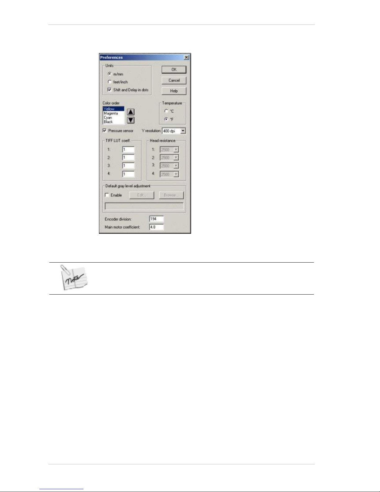
Software Preparations for Printing Preparing Your Printer for Printing
8-28 Sprinter User's Manual
Setting the Preferences
Figure 8-21: The Preferences dialog box
The Encoder Division and Main Motor Coefficient parameters must be checked
immediately after the software installation.
Use the P
REFERENCES dialog box to set your printing preferences.
Use the P
REFERENCES dialog box to specify the unit of measure and the
color order for printing. The H
EAD RESISTANCE feature is not yet
implemented.
Setting the Encoder Division and Main Motor Coefficient
These two parameters are related to the main pulling system.
Page 89

Preparing Your Printer for Printing Software Preparations for Printing
Sprinter User's Manual 8-29
Setting the Encoder Division
The ENCODER sends pulses to the MAIN MOTOR.
Set the E
NCODER PARAMETER according to the following table:
Printer Type Motor Type Encoder Location Encoder Parameter
Sprinter A On the Rubber Roller 7
SprinterB 36/40 Small Motor On the Motor 202
SprinterB 36/40 Large Motor On the Motor
194
SprinterB 36/40 On the Rubber Roller 7
Main Motor Coefficient
The MAIN MOTOR COEFFICIENT controls the speed of the MAIN MOTOR.
Set the M
AIN MOTOR COEFFICIENT PARAMETER according to the following
table:
Printer Type Main Motor Coefficient Parameter
Sprinter A 1
SprinterB 36/40 ~5.4*
*This parameter is subject to change, based on speed tests performed in
the C
ONTROL dialog box, in order to obtain 60m/hr at "ultra" speed mode.
As an example, if the print test results show 65m/hr., then
THE MAIN
MOTOR COEFFICIENT PARAMETER must be reduced. This parameter should be
adjusted in order to give a maximum speed of 60m/hr.
Selecting the Y Resolution
Select the Y Axis resolution according to the following options:
Printer Type Y Resolution Option
Sprinter A 400 x 400 dpi
SprinterB 36/40 400 x 400 dpi, 400 x 200 dpi
Page 90

The Printing Procedure Preparing Your Printer for Printing
8-30 Sprinter User's Manual
Adjusting the TIFF LUT Coefficient
The TIFF LUT coeffecient feature (which works only with TIFF files,)
enables you to adjust the density percentage of each color. An increase of
'0.1' will increase the density by 10%, '0.2' will increase it by 20%, and a
maximum increase of '0.3', will increase the density by 30%. Similarly, a
decrease to '0.9', will decrease the color density by 10%. The minimum
decrease is –30%.
You can adjust by single percentage units by entering a second decimal
place. E.G., an entry of '1.15', will increase the color density by 15% and
an entry of '0.95' will decrease the color density by 5%.
Adjusting the Gray Level on all enqueued TIFF files
The GRAY LEVEL feature is accessible either from the EDIT dialog box (as in
previous versions,) or the P
REFERENCES dialog box.
You can either adjust the G
RAY LEVEL on all the TIFF files using the
P
REFERENCES dialog box, or on specific ones, using the EDIT dialog box
(Error! Reference source not found.)
The G
RAY LEVEL can be adjusted for TIFF files only (50 dpi). You can also
use the
GRAY LEVEL settings that have been saved previously.
Once you adjust a file's GRAY LEVEL through the EDIT dialog box it will not be
affected if you subsequently carry out a global GRAY LEVEL adjustment through
the PREFERENCES dialog box.
! To adjust the Gray Level of all the TIFF files:
1. From the M
AIN SCREEN, click PREFERENCES.
The P
REFERENCES dialog box appears (Error! Reference source not
found.).
2. In the Default G
RAY LEVEL ADJUSTMENT group box, click ENABLE.
3. Carry out the same procedures as you would through the E
DIT dialog
box.
4. To close the P
REFERENCES dialog box click OK.
The Printing Procedure
This section sets out all the operating procedures involved in actually
producing your printed work.
Importing a file to the Printing Menu
You import files to the Printing Menu using the Import File dialog box.
Checking the S
HOW PREVIEW option will enable you to preview the selected
file in the right hand corner of the dialog box.
Checking the Delete source option will cause any imported deletable file to
be removed once it is imported. If the file's source is a CD for example, you
will not be able to delete it.
Page 91
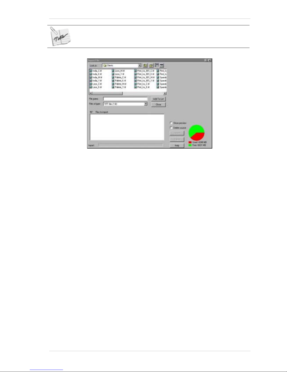
Preparing Your Printer for Printing The Printing Procedure
Sprinter User's Manual 8-31
Once selected, the delete source option affects all the displayed deletable
imported files.
Figure 8-22: The Import File Dialog Box
! To import a image:
1. From the M
AIN SCREEN, click IMPORT.
The I
MPORT FILE dialog box appears (Error! Reference source not
found.). The name of the current drive and directory appears in the
Look in: field.
You can choose the correct path if necessary.
If required, check t he S
HOW PREVIEW option to view the selected field.
If you wish to remove the selected deletable files from their source,
check the D
ELETE SOURCE option.
2. Select the required file.
If the file comprises four separations (C. M. Y, or K), select one of them
and the application will automatically select the others.
If you have more than one file to import, click A
DD TO LIST.
The name of the selected file appears in th e F
ILES TO IMPORT section of
the dialog box.
The printer will only import files in the following formats:
.tif, _c.tif, _m.tif, _y.tif, _k. tif, or _001_c.tif, _001_m.tif, _001_y.tif,
_001_k.tif.
If you attempt to import files of another format, an appropriate
message appears.
If you have other files to import, repeat steps 1-4.
If you wish to rotate the image 90° clockwise, select the file, and click
A
DD TO LIST.
3. Check the option box that appears before the selected file name in the
F
ILES TO IMPORT window.
4. To add the selected files to the print list of the M
AIN SCREEN, click
I
MPORT.
Page 92
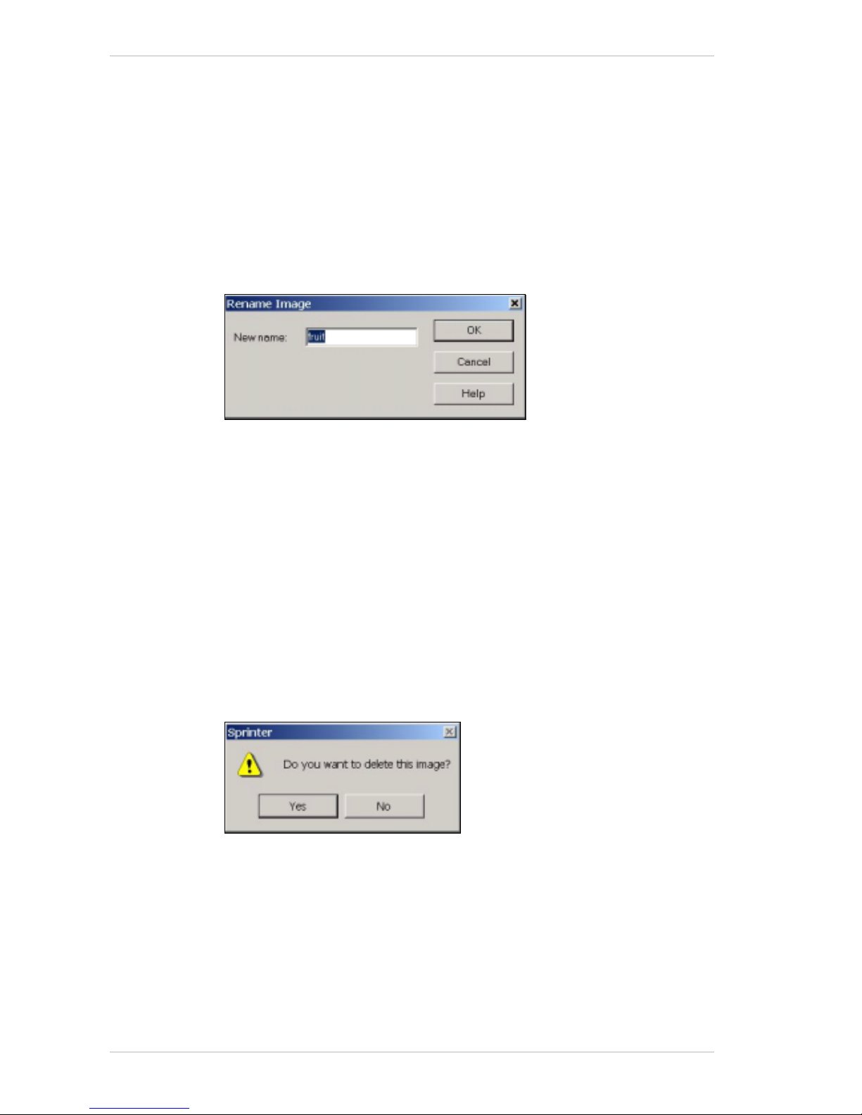
The Printing Procedure Preparing Your Printer for Printing
8-32 Sprinter User's Manual
Deleting a Selected File from the Import File Dialog Box
! To delete a file:
1. From the F
ILES TO IMPORT BOX in the IMPORT FILE dialog box, select the
image you wish to delete.
2. Click D
ELETE.
Renaming a File
This procedure can be carried out either from the MAIN SCREEN or from the
I
MPORT FILE dialog box.
Figure 8-23: The Rename Image dialog box
! To rename a file from the Main Screen:
1. Select the required file from the P
RINTING MENU of the MAIN SCREEN.
2. From the I
MAGE menu of the MAIN SCREEN, select RENAME.
3. The R
ENAME IMAGE dialog box appears (Figure 8-23).
4. In the N
EW NAME field, enter the new name of the file and click OK.
! To rename a file from the Import File dialog box:
1. Right-click the required file from the upper window of the I
MPORT FILE
dialog box and select R
ENAME from the menu that appears.
2. Rename the file and click outside the file name.
Deleting a File from the Printing Menu
Figure 8-24: The Delete Prompt
! To delete a file:
1. Select the required file from the P
RINTING menu of the MAIN SCREEN.
2. From the I
MAGE menu of the MAIN SCREEN, select DELETE.
The D
ELETE PROMPT appears (Figure 8-24).
3. Click Y
ES to confirm the delete command.
Page 93
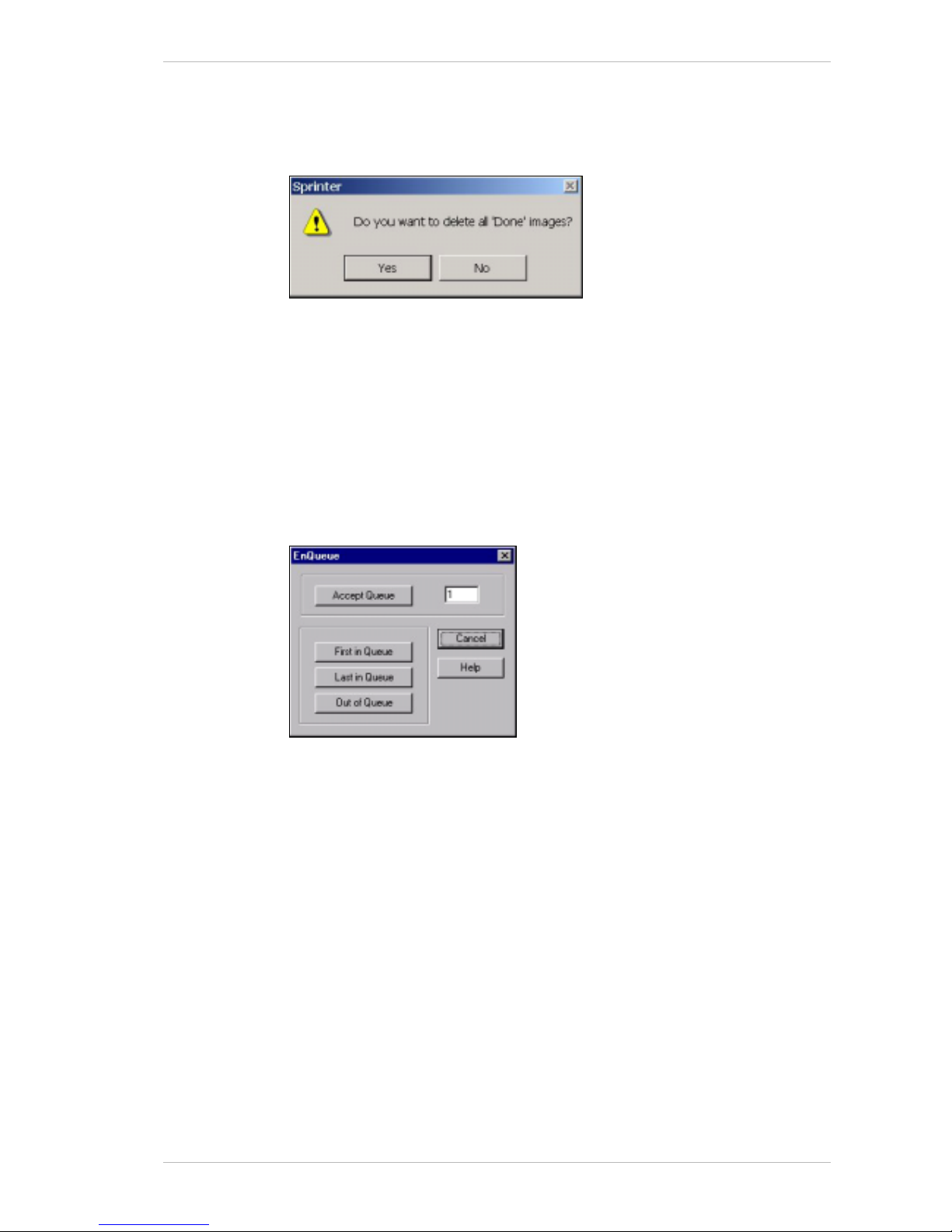
Preparing Your Printer for Printing The Printing Procedure
Sprinter User's Manual 8-33
Deleting Printed Files
When a file has been pr inted, the word ‘DONE’ appears in the QUEUE
column of the Print menu.
Figure 8-25: The Delete 'Done' Prompt
! To delete printed files:
1. From the I
MAGE menu of the MAIN SCREEN, select DELETE ‘DONE’.
The D
ELETE ‘DONE PROMPT appears (Figure 8-25).
2. Click Y
ES to confirm the delete command.
Queueing the Files for Printing
To determine the order in which the selected files are printed, you should
use the Q
UEUE command.
Figure 8-26: The Enqueue Dialog Box
! To queue a file for printing:
1. From the M
AIN SCREEN, click QUEUE, or right click the mouse.
The E
NQUEUE dialog box appears (Error! Reference source not
found.).
2. Carry out the following steps as required:
To put the selected file first in the queue, click F
IRST IN QUEUE.
The selected file appears first in th e queue of the P
RINT menu.
To put a selected file next in the queue, click L
AST IN QUEUE.
The selected file appea rs after the first file in the queue of the P
RINT
menu.
To place a selected file anywhere in the queue except l a st, click A
CCEPT
QUEUE, specify in the text field the required number in the QUEUE and
then click A
CCEPT QUEUE.
To remove a file from the queue, select the file and click O
UT OF QUEUE.
Page 94
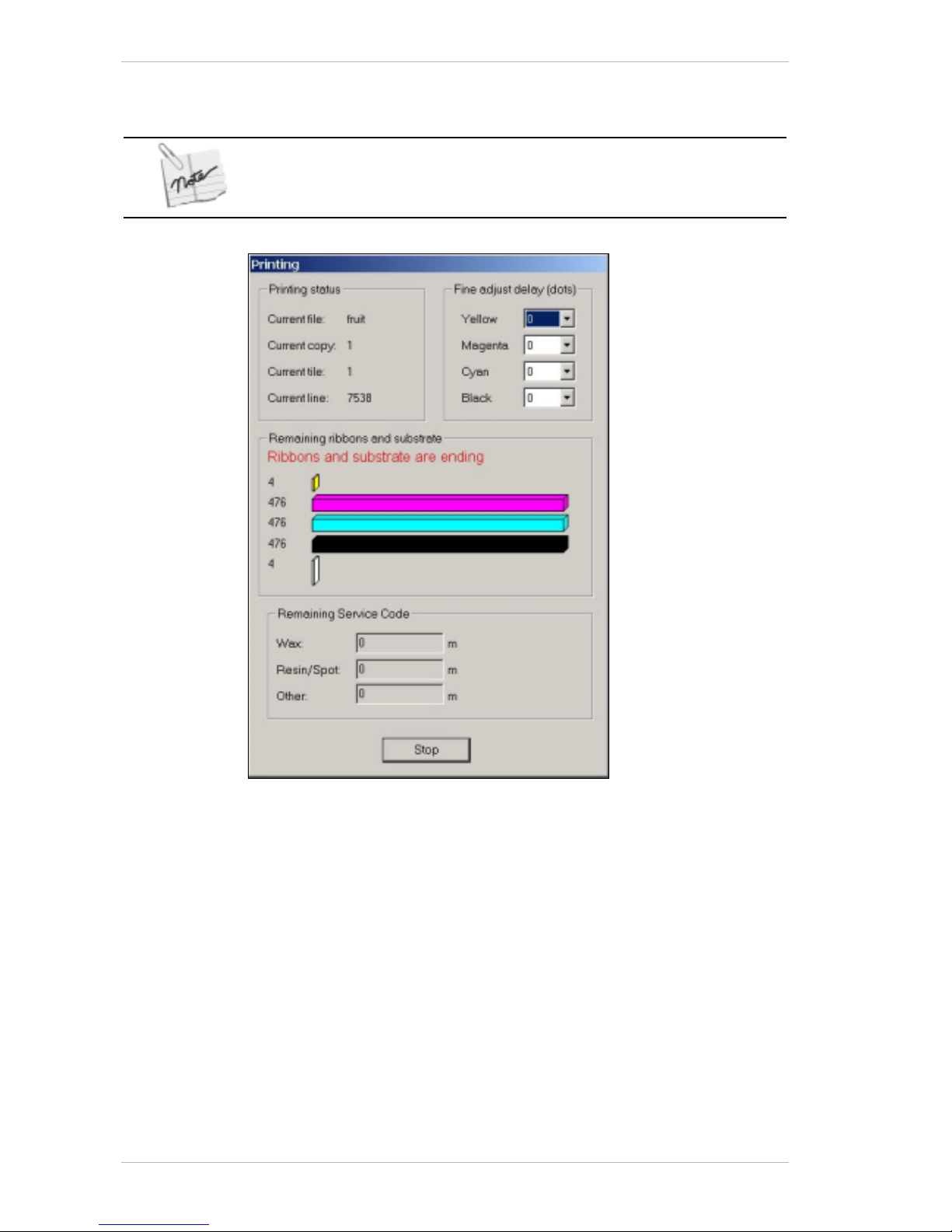
The Printing Procedure Preparing Your Printer for Printing
8-34 Sprinter User's Manual
Printing the Files Queued on the Print Menu
Before printing the required files, you should read the following information on
the Online Delay feature.
Figure 8-27: The Printing Dialog Box
The On-the-fly Fine Adjust Delay
Although the HEAD DELAY feature is accessible from the CONFIGURATION
dialog box for setting before a print session, you can also adjust the H
EAD
DELAYS while printing, through the PRINT command. This is called ONLINE
HEAD DELAY adjustment.
The adjustment will only take effect from the printing of the next file in the
queue. The new delay value(s) will be applied to the remaining files in the
queue and the values in the C
ONFIGURATION dialog box are automatically
adjusted. Further adjustments may be made on later enqueued files, and
those values will also be automatically adjusted in the C
ONFIGURATION
dialog. The values i n the dialog box are those t hat were adjusted last. The
values in the P
RINTING dialog box returns to zero at the beginning of the
next print session.
This adjustment can be carried out as many times as required during the
print session.
Page 95
Preparing Your Printer for Printing The Printing Procedure
Sprinter User's Manual 8-35
The reference is to the distance in dots from each PRINT HEAD to the first
one.
The first P
RINT HEAD (the Yellow,) is therefore always referenced as zero. For
initial reference, the distanc e between each P
RINT HEAD is about 4,000
dots. However, if the Y
ELLOW HEAD has to be adjusted, this can be done in
the P
RINT dialog box, in one of two ways, as shown in the following
example:
If the Yellow precedes the other three colors by 10 dots, you can either
adjust each of the CMK H
EADS by '–10', or adjust the Yellow by +10. This
will result in the new H
EAD DELAY value for the CMK HEADS being r educed
by 10 units in the C
ONFIGURATION dialog box and the Yellow's value
remaining at zero.
! To print the enqueued files and carry out the optional O
NLINE HEAD
DELAY adjustment:
1. Run a check of all the settings in the E
DIT, CONFIGURATION and CONTROL
dialog boxes.
2. From the M
AIN SCREEN, click PRINT.
The P
RINTING dialog box appears (Error! Reference source not found.).
The software loads the printer and the printing process commences.
If required, during the printing process, adjust the H
EAD DELAY in the
relative drop-down combo box.
You can monitor the printing process from the P
RINTING dialog box, in
the P
RINTING STATUS group box.
You can also monitor the remaining quantity of Ribbon and Substrate
installed on the printer, from the R
EMAINING RIBBONS AND SUBSTRATE
group box.
When the printing process is complete, the P
RINTING dialog box closes
and the word ‘D
ONE’ appears next to the queued fi les, on the MAIN
SCREEN.
3. Click the U
NLOAD icon in the MAIN SCREEN.
When the printing is complete, the 24v power supply shuts down
automatically.
When the amount of any Ribbon reaches 10m and that of the Substrate
reaches 5m, a red warning is displayed in the Printing dialog box.
Do not leave the Rubber Rollers in the UP position for more than 60 seconds.
If more than 60 seconds do pass, the software will automatically bring them
down.
Page 96
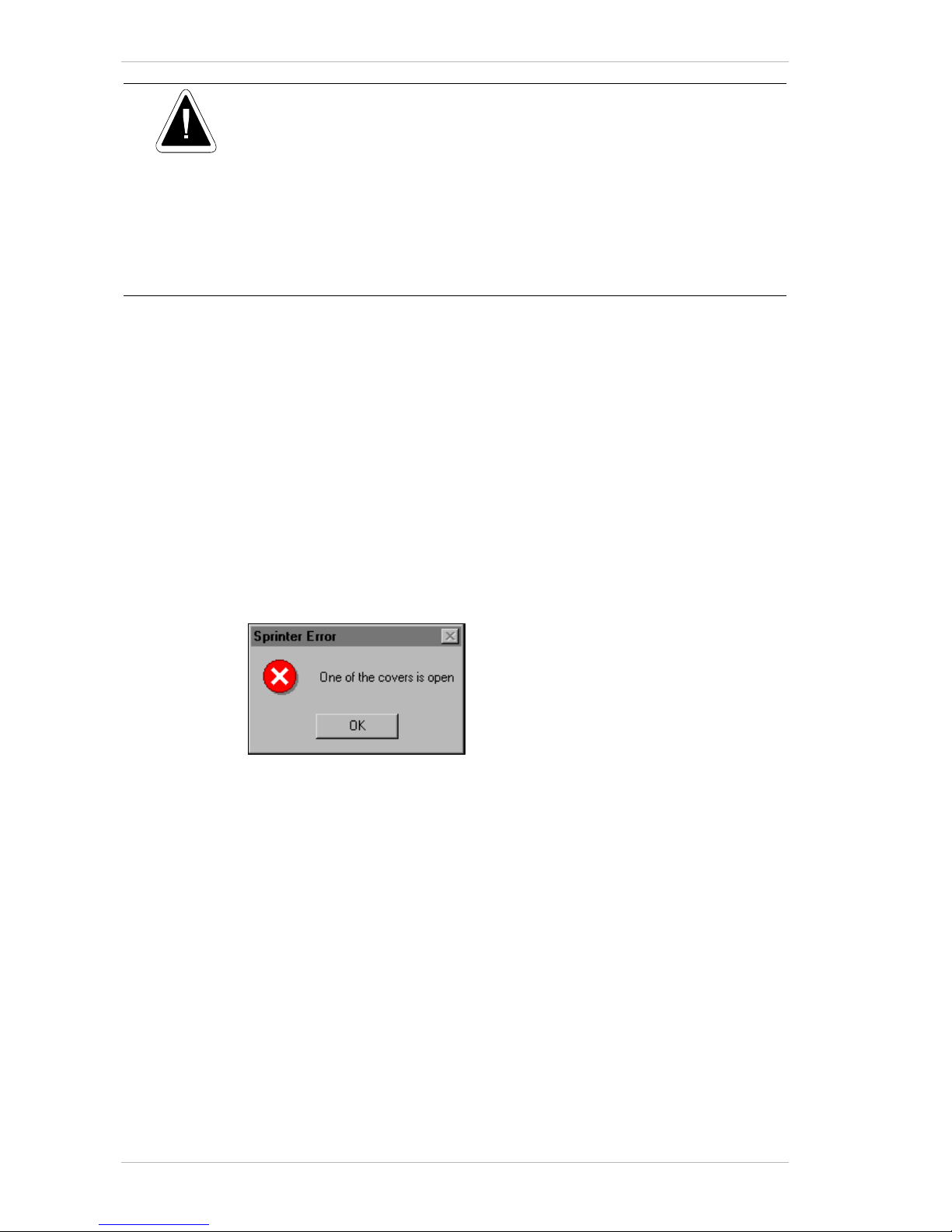
Shutting Down the System Preparing Your Printer for Printing
8-36 Sprinter User's Manual
If the printer does not respond to commands given by the computer or if there is
any problem that requires a immediate stop, press one of the red Emergency
Stop buttons, located at the front and rear of the printer.
Pressing the Emergency Stop button shuts down the power to the printer as well
as to the computer. The files displayed in the Print menu of the Main Screen will
not be deleted.
You can release the Emergency Stop button by turning it in a clockwise
direction.
Return the Circuit Breaker switch to the ON position.
Press the button next to the Main Circuit Breaker Switch.
The Safety Switches
To prevent injury during printing, the printer is equipped with five
Interlock switches, at the following locations:
• For the F
RONT COVER.
• For the T
OP DOOR COVER.
• For the S
UBSTRATE PASS DOOR.
• For the R
EAR COVER.
• For the S
UBSTRATE COLLECTOR ROLLER COVER.
The switches are engaged whenever any of the above covers or doors are
opened during printing. When this occurs, the following warning is
displayed:
Shutting Down the System
When the printing run is complete and you don’t intend to work for the
remainder of the day or for a longer period of time, you should shut down
system down.
! To shut the system down:
1. Click the U
NLOAD icon in the MAIN SCREEN.
2. Make a visual check to confirm that the printer is in the U
NLOAD mode.
The P
ULLING ARM should be up.
The R
UBBER ROLLER should be down.
3. Shut down the PC.
If you wish to shut the system down for a long period of time, shut
down the main switch located at the back of the printer.
4. Place a sponge under the P
ULLING ARM.
5. Close all the Printer’s covers.
Page 97
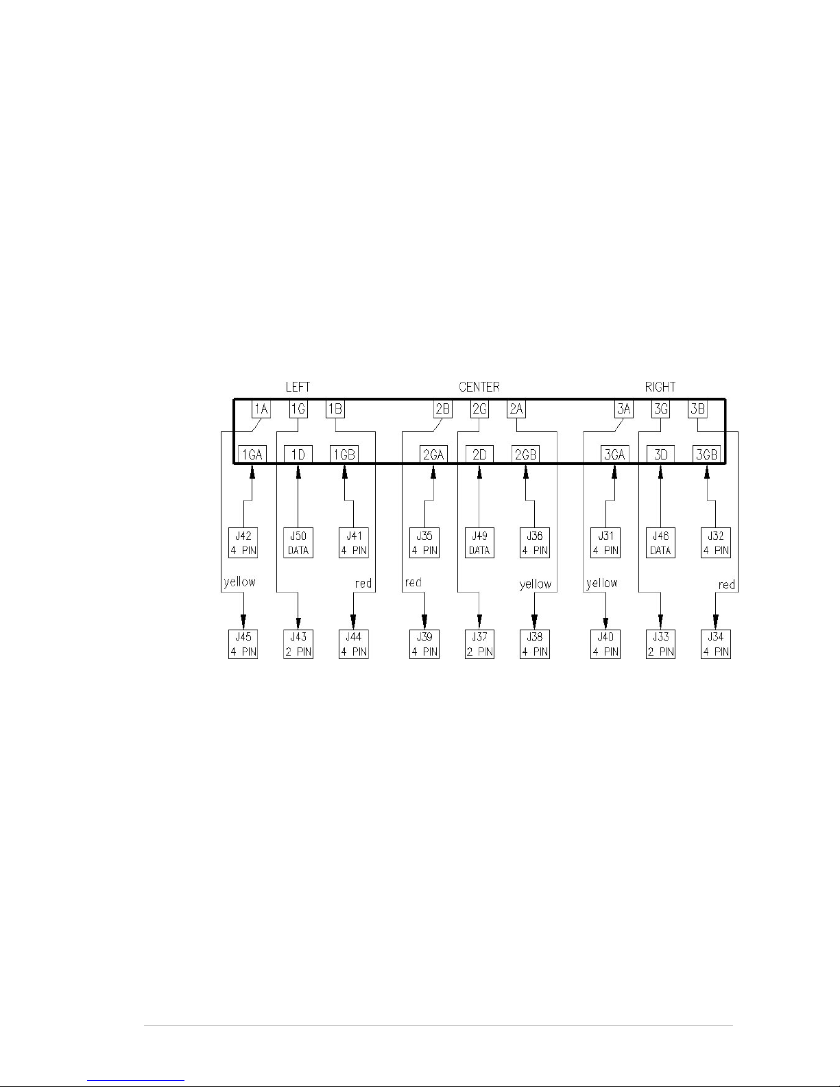
Sprinter User's Manual 9-1
9 Replacing and Adjusting the Print Heads
The PRINT HEADS are already preinstalled on the printer. They have also
been calibrated.
To facilitate the correct connection of the cables, they are color coded and
labeled. The connector pins on the P
RINT HEADS are also labeled.
Black cables are ground, red and yellow are current, and any other colors
carry the data.
The P
RINT HEAD is connected to the PRINT HEAD CARD by a number of
cables. These cables either carry current or data.
If the P
RINT HEAD CARD on your printer has three sets of connector pins,
you should connect the cables according to Figure 9-1. If it has four sets,
you should connect the cables according to Figure 9-2, page 9-2.
Figure 9-1: Wiring between the Head Card and the Print Head
Page 98
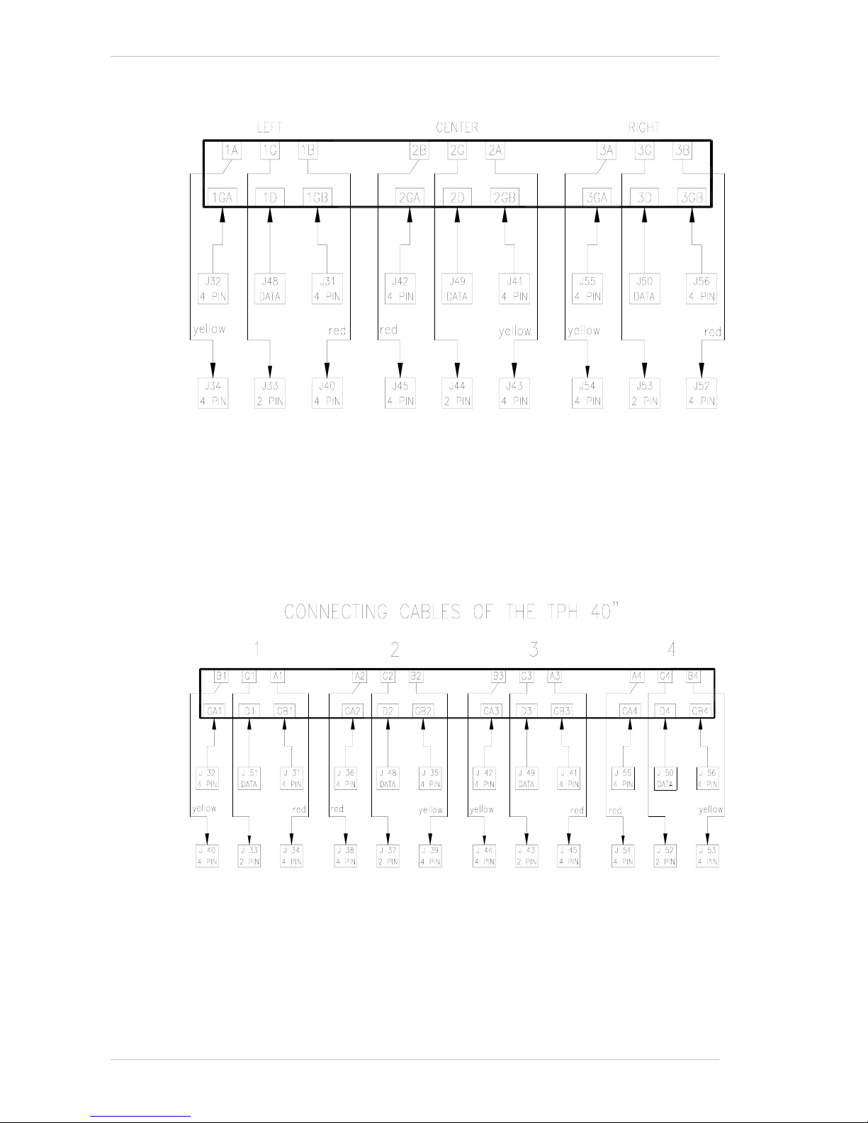
Replacing a Print Head Replacing and Adjusting the Print Heads
9-2 Sprinter User's Manual
Figure 9-2: Wiring Between the Head Card and the Print Head (Universal)
If your printer is the SprinterB 40", you should connect the cables
according to Figure 9-3.
Figure 9-3: Wiring Between the Universal Head Card and the 40" Print Head
Wiring Between the Head Card and the Print Head (Universal)
Page 99

Replacing and Adjusting the Print Heads Replacing a Print Head
Sprinter User's Manual 9-3
Replacing a Print Head
Before touching any part of the ceramic surface on the Print Head, you must wear
anti-static gloves. Do not touch any part of the ceramic surface with your bare
hands.
To replace a Print Head:
1. Make sure the rubber rollers are down.
2. Turn off the computer.
3. Remove the R
IBBON, using that particular PRINT HEAD.
4. Remove the H
EAD CARD COVER.
5. Ensure that the S
UBSTRATE is loaded, thus preventing any item falling
directly onto the rollers and causing damage.
6. Remove all cables connected to the P
RINT HEAD from both sides.
7. Release the M
OUNTING SCREWS and hold the PRINT HEAD with your hand,
to prevent it from falling.
8. When it is released from the M
OUNTING SCREWS, lower the PRINT HEAD,
gently tilt it perpendicularly and lift it away from the printer.
Alternatively, you can lower the P
RINT HEAD onto the Rubber Rollers,
open the S
UBSTRATE PASS DOOR and pass it out through the opening.
9. Make sure that all four M
OUNTING SCREWS are still in place.
10. Carefully remove the new P
RINT HEAD from its packaging.
11. Check for any damage.
Immediately report any damage to your Matan Distributor.
12. Clean the ceramic surface with the enclosed swab, using alcohol 100%.
13. Hold the P
RINT HEAD at both ends, turn it so it is perpendicular and
lower it onto the R
UBBER ROLLER.
Alternatively, you can pass it through the opening of the S
UBSTRATE
PASS DOOR.
14. Hold the P
RINT HEAD with one hand and with the other, ensure that all
the cables are positioned so that the P
RINT HEAD has free uninterrupted
access to the C
OOLING CHANNEL.
15. Push up the P
RINT HEAD further against the COOLING CHANNEL until the
four mounting screws in the C
OOLING CHANNEL, move in their place.
16. Tighten one M
OUNTING SCREW in each of the two groups so that the
head is held in position against the C
OOLING CHANNEL without your
support.
17. There are at least two P
RINT HEAD STOPS on the PRINT HEAD ASSEMBLY
(Figure 9-4, page 9-4).
Ensure that the P
RINT HEAD is in contact with all the PRINT HEAD STOPS.
Page 100
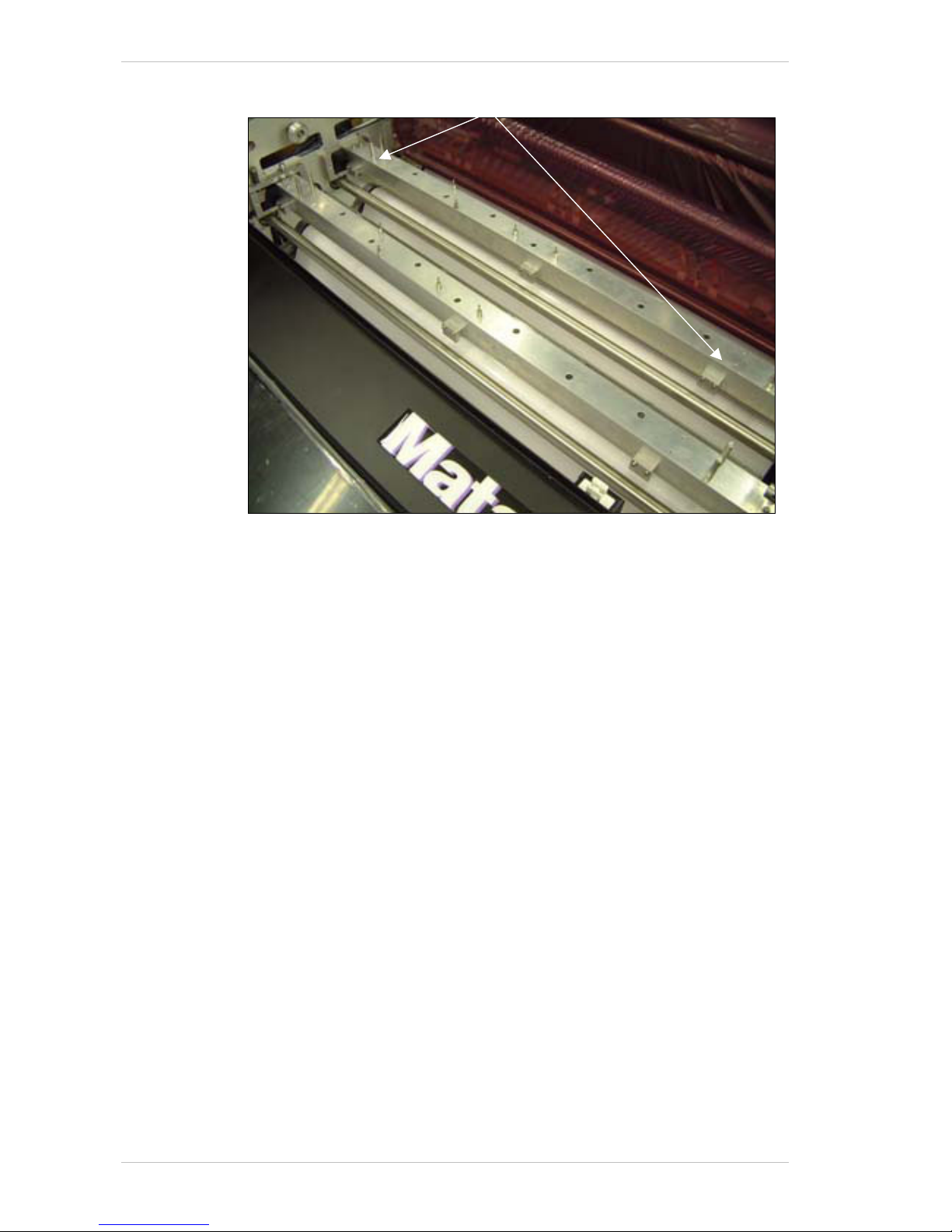
Replacing a Print Head Replacing and Adjusting the Print Heads
9-4 Sprinter User's Manual
Figure 9-4: The Print Head Stops
18. Tighten the two groups of the MOUNTING SCREWS so that the PRINT HEAD
is touching the metal surface. Check that at no point along the P
RINT
HEAD'S length is there a gap between it and the COOLING CHANNEL and
that no cables are caught in between.
19. Reconnect the cables to the P
RINT HEAD.
20. Cut the S
UBSTRATE next to the SUBSTRATE ROLL, and remove it from the
printer.
21. Reinstall a new S
UBSTRATE on the printer.
Print Head Stops
 Loading...