

Page 1
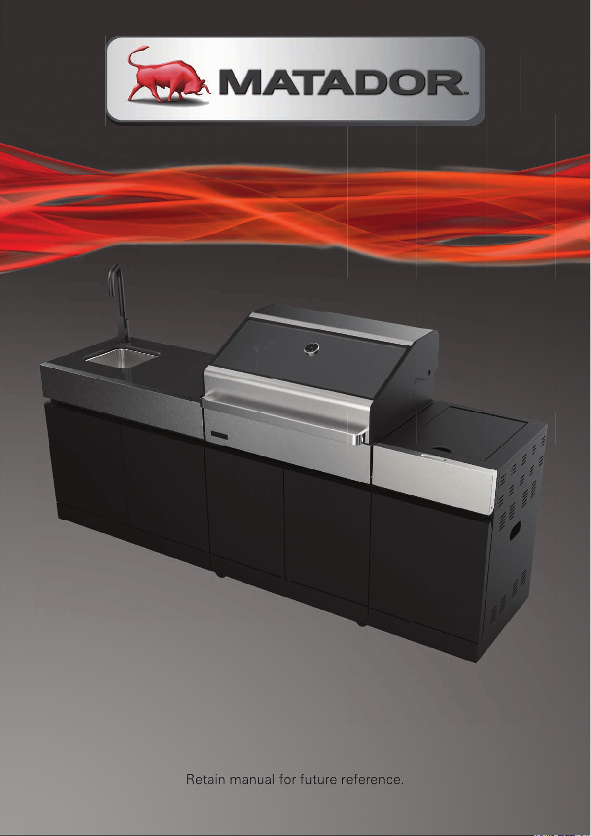
PALLADIUM 4 BURNER KITCHEN BBQ
Model: HS-18MAK600
Retain manual for future reference.
Page 2

CONTENTS
FEATURES AND BENEFITS
IMPORTANT SAFETY WARNINGS
GAS LEAK TEST
GAS EMERGENCY PROCEDURE
GENERAL INFORMATION
EXPLODED PARTS VIEW
PARTS LIST
HARDWARE PACK
ASSEMBLY STEPS
BBQ LOCATION – OUTDOOR AREA
CONNECTION TO LPG
LIGHTING PROCEDURE
USING THE BBQ
USING THE SMOKER BOX
BBQ TIPS
BBQ MAINTENANCE
SPECIFICATIONS
CONNECTION TO NATURAL GAS
WARRANTY
3
4
5
6
7
8
9
12
13
37
39
40
41
42
43
44
51
52
54
Page 3
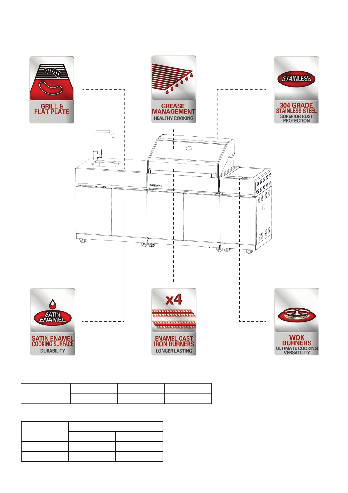
FEATURES & BENEFITS
Overall Barbecue Dimensions
4B
Freestanding
Length Height Depth
2135 mm 1195 mm 654 mm
Gas Output
Gas Type
BBQ Side
LPG / U-LPG 15 MJ/h 15 MJ/h
Natural Gas 15 MJ/h 15 MJ/h
Burner
MATADOR INSTRUCTION MANUAL 3
Page 4

IMPORTANT SAFETY
WARNINGS
FOR OUTDOOR USE ONLY
DO NOT OPERATE THIS APPLIANCE BEFORE READING THE INSTRUCTION
1.
BOOKLET.
DO NOT PLACE ARTICLES ON OR AGAINST THIS APPLIANCE.
2.
DO NOT STORE CHEMICALS OR FLAMMABLE MATERIALS OR SPRAY
3.
AEROSOLS NEAR THIS APPLIANCE.
DO NOT OPERATE THIS APPLIANCE INDOORS.
4.
DO NOT ENCLOSE THIS APPLIANCE.
5.
DO NOT LIGHT OR OPERATE WITH COVER ON.
6.
Servicing can only be carried out by authorised technicians or licensed gas
7.
fitters.
Conduct a thorough gas leak check every time the cylinder is replaced or
8.
reconnected.
Do not store chemicals or flammable materials near this appliance.
9.
Children must be supervised at all times while they are in the vicinity of this
10.
BBQ to prevent burn injuries and to ensure they do not attempt to use the
BBQ.
In case of a fat fire, immediately isolate the gas supply - turn the LPG cylinder
11.
valve off.
Allow the BBQ to cool before removing the drip tray. Hot fat can cause serious
12.
injury.
This BBQ should not be located under overhead combustible construction.
13.
Maintain the following minimum clearances to combustibles at all times:
14.
From sides: 200mm From back: 500mm Overhead:1000mm
Turn all gas valves off including the LPG cylinder valve after use.
15.
Never leave burners on high for more than 10 minutes unless actually cooking.
16.
If the burner makes a loud roaring sound when lit, it may be burning inside. If
this occurs, turn the burner off, allow it to cool and light it again.
17.
Do not delay ignition and allow a buildup of unburned gas.
18.
Remove stickers (where fitted) from hood before use.
19.
Do not store a spare LPG cylinder in the vicinity of the BBQ.
Page 5
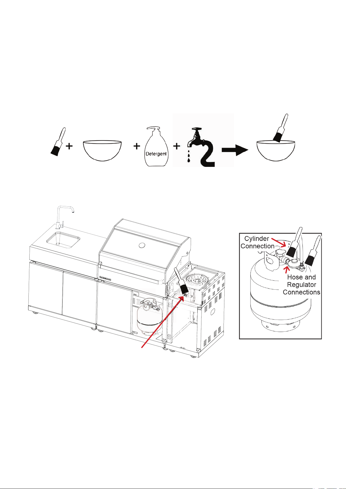
GAS LEAK TEST
Gas connections on the barbecue are leak tested at the factory prior to shipment
however, a complete gas leak test must be performed during assembly. The
cylinder to regulator connection must be leak tested every time the connection is
made. In order to test for a gas leak, complete the following steps.
1. Make a soap solution of one part liquid detergent and one part water.
2. Ensure that the barbecue control knobs and LPG is turned off. Open the LPG
cylinder valve and apply the soap solution to the gas connections using a soft
bristle brush as seen below.
Barbecue
connection
Soap bubbles will appear if there is a gas leak. In case of a leak, turn off the gas
supply. Tighten any leaking fittings, then turn the gas supply on and re-check.
Warning: Do not operate the appliance until all gas leaks have been rectified.
Never complete a gas leak test while smoking.
Note: If there is a leak anywhere on the gas cylinder, do not use the cylinder.
Locate the leaking cylinder outdoors away from sources of ignition, then contact
your local gas authority or cylinder exchange provider to arrange disposal.
MATADOR INSTRUCTION MANUAL 5
Page 6

GAS EMERGENCY
removed from the BBQ.
side.
heavy-duty cover (not included).
other flammable vapours and liquids.
WWAARRNNIINNGG
SSTTOORREE CCYYLLIINNDDEERR IINN AA WWEELLLL VVEENNTTIILLAATTEEDD AARREEAA
OOUUTT OOFF RREEAACCHH OOFF CCHHIILLDDRREENN
PROCEDURE
A strong gas smell or hissing sound indicates a serious problem with your BBQ or
the LPG gas cylinder. Failure to immediately follow the steps listed below could
result in property damage, serious bodily injury, or even death. If a strong smell of
gas or hissing sound occurs, complete the following steps.
1. Shut off the LPG cylinder valve.
2. Turn the control knobs to OFF position.
3. Put out any flame with a class B fire extinguisher and clear the area of people.
4. Move away from the LPG gas cylinder.
5. Do not try to fix the problem yourself.
If odour continues or you have a fire you cannot extinguish, call the fire
department immediately.
WARNING
STORE CYLINDER IN A WELL VENTILATED AREA
STORE CYLINDER OUT OF REACH OF CHILDREN
Page 7

GENERAL INFORMATION
Note: Before using the BBQ, remove any packaging material within and around
-
the BBQ supplied for protection during transit.
Improper installation, adjustment, alteration, service or maintenance can
-
cause property damage, injury or death. Read the installation, operating
and maintenance instructions thoroughly before installing or servicing this
equipment.
Strong winds and low temperatures can affect the heating and performance of
-
your BBQ so factor in these elements when positioning your BBQ outdoors for
cooking.
Never use your BBQ in a garage, porch, shed, breezeway or any other enclosed
-
area. Your BBQ is to be used outdoors only,. Do not obstruct the flow of
ventilation air around the BBQ. This BBQ is not intended to be installed in or on
recreational vehicles and/or boats.
Warning: accessible parts may be very hot. Keep young children away.
-
Do not move the appliance during use.
-
Any modification of the appliance may be dangerous.
-
Do not replace the grill with an extra hotplate. The warranty will become null and
-
void.
Note: The normal flow of gas through the Regulator and Hose Assembly can
-
create a humming sound. A low volume of sound is perfectly normal and will not
interfere with operation of the BBQ. If humming sound is loud and excessive you
may need to purge air from the gas line.
Do not store gas cylinders below ground level. LP gas is heavier than air so if a
-
leak occurs the gas will collect at a low level and could ignite in the presence of a
flame or spark.
You must have the correct gas cylinder, regulator and hose for this BBQ to
-
operate safely and efficiently. Use of an incorrect gas cylinder, regulator or hose
is dangerous and will void the warranty on this product.
MATADOR INSTRUCTION MANUAL 7
Page 8
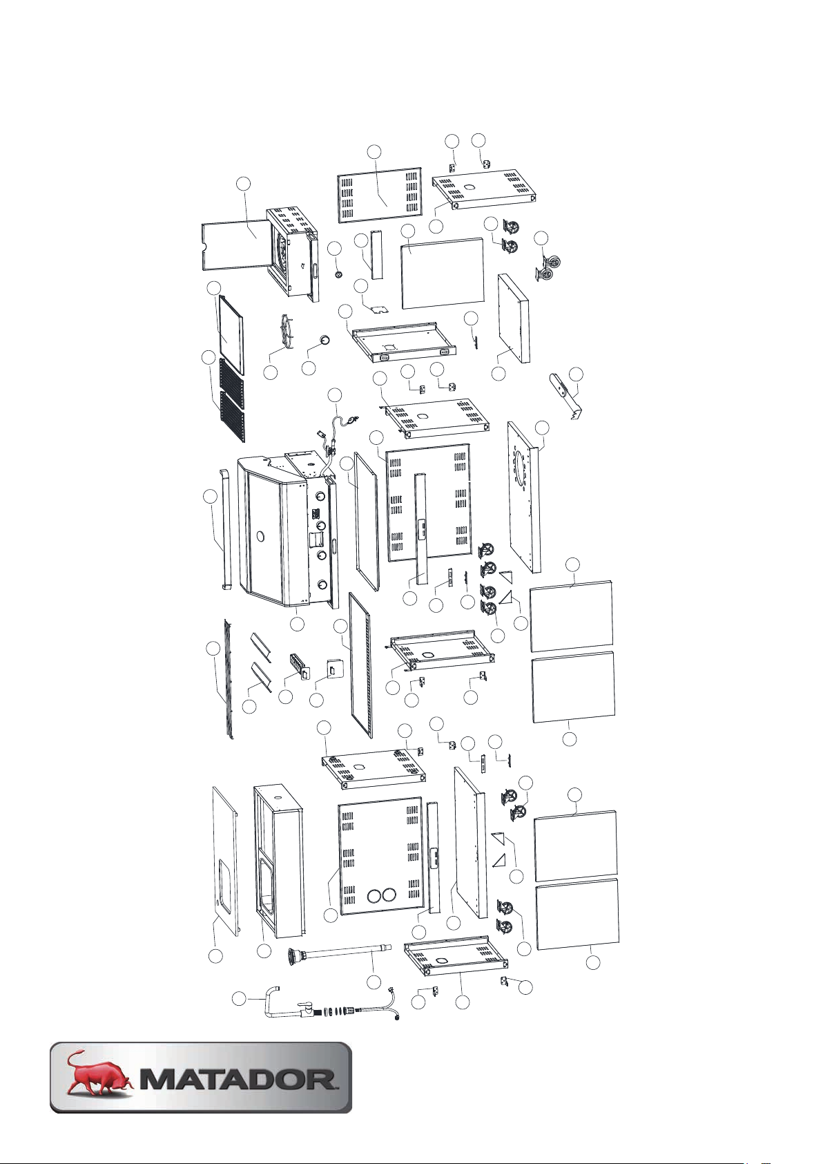
EXPLODED PARTS VIEW
Exploded View
43
42
44
37
41
40
38
6
7
21
18
11
39
3
28
1
2
30
35
10
27
26
5
11
19
22
17
31
36
34
33
32
29
23
24
20
8
9
8
9
8
9
21
15
16
18
12
46
13
14
25
6
7
4
15
16
16
21
22
22
19
45
21
Page 9
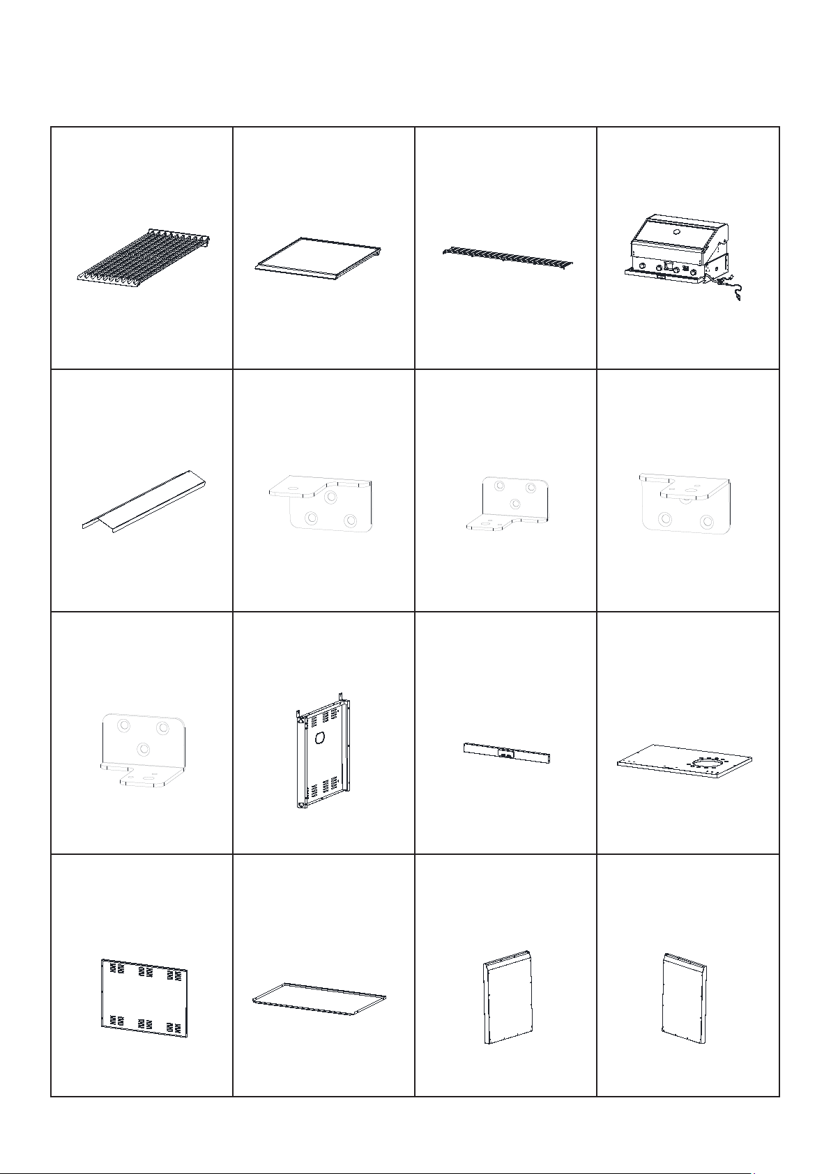
PARTS LIST
cabinet
1 Cooking grill x 2
2 Hotplate
3 Warming rack
4 Firebox
4 Firebox
8 Side burner trivet
12 Bottom panel of
cabinet
1 Cooking grill x 2
2 Hotplate
3 Warming rack
4 Firebox
5 Flame tamer x2
6 Left side table
7 Right side burner
table
8 Side burner trivet
4 Firebox
3 Warming rack
4 Firebox
2 Hotplate
3 Warming rack
4 Firebox
3 Warming rack
4 Firebox
table
8 Side burner trivet
11 Crossbeam
12 Bottom panel of
cabinet
2 Hotplate
3 Warming rack
4 Firebox
7 Right side burner
table
8 Side burner trivet
cabinet
11 Crossbeam
12 Bottom panel of
cabinet
4 Firebox
table
8 Side burner trivet
12 Bottom panel of
cabinet
16 Right door
2 Hotplate
3 Warming rack
4 Firebox
6 Left side table
7 Right side burner
table
8 Side burner trivet
cabinet
11 Crossbeam
12 Bottom panel of
cabinet
cabinet
15 Left door
16 Right door
2 Hotplate
3 Warming rack
4 Firebox
6 Left side table
7 Right side burner
table
8 Side burner trivet
9 Regulator 10 Left side panel of
cabinet
11 Crossbeam
12 Bottom panel of
cabinet
14 Separation panel of
cabinet
15 Left door
16 Right door
cabinet x 2
19 Magnet plate
20 Castor without lock x
2
26 Smoker box
27 Grease cup
28 Handle of hood
31 Left door hinge
-Down
32 Right door hinge
-Upper
19 Magnet plate
20 Castor without lock x
2
27 Grease cup
28 Handle of hood
-Down
32 Right door hinge
-Upper
18 Side panel support of
cabinet x 2
19 Magnet plate
20 Castor without lock x
2
25 Grease tray
26 Smoker box
27 Grease cup
28 Handle of hood
29 Scraper tool
30 Left door hinge -Upper
31 Left door hinge
-Down
32 Right door hinge
-Upper
2
-Upper
1. Cooking Grill x 2 2. Hotplate 3. Warming rack 4. Firebox
5. Flame tamer x 2 6. Left door hinge
- upper x2
9. Left door hinge
- lower x3
10. Left side
cabinet panel
7. Left door hinge
- lower x2
8. Right door
hinge - upper x3
11. Crossbeam x2 12. Bottom
cabinet panel
13. Back cabinet
panel
14. Separation
cabinet panel
15. Left door x2 16. Right door x3
MATADOR INSTRUCTION MANUAL 9
Page 10

PARTS LIST
2
2
19 Magnet plate
20 Castor without lock x
2
cabinet x 2
19 Magnet plate
20 Castor without lock x
2
18 Side panel support of
cabinet x 2
19 Magnet plate
20 Castor without lock x
2
20 Castor without lock x
2
cabinet x 2
19 Magnet plate
20 Castor without lock x
2
18 Side panel support of
cabinet x 2
19 Magnet plate
20 Castor without lock x
2
2
28 Handle of hood
18 Side panel support of
cabinet x 2
19 Magnet plate
20 Castor without lock x
2
21 Castor with lock x 2 22 Plastic backing board 23 Control knob 24 Seat of control knob
25 Grease tray
26 Smoker box
27 Grease cup
28 Handle of hood
20 Castor without lock x
2
27 Grease cup
28 Handle of hood
cabinet x 2
19 Magnet plate
20 Castor without lock x
2
26 Smoker box
27 Grease cup
28 Handle of hood
4 Firebox
8 Side burner trivet
20 Castor without lock x 2
24 Seat of control knob
28 Handle of hood
32 Right side panel of
right side cabinet
cabinet x 4
19 Magnet plate x2
20 Castor without lock x 2
3
23 Control knob
24 Seat of control knob
27 Grease cup
28 Handle of hood
31 Left side panel of
right side cabinet
32 Right side panel of
right side cabinet
17. Right side
cabinet panel
21. Castor with
lock x 10
18. Side cabinet
panel support x4
22. Plastic backing
board x3
19. Magnet plate x220. Castor without
lock x2
23. Control knob 24. Seat of control
knob
25. Grease tray 26. Smoker box 27. Grease cup 28. Hood handle
29. Side burner
trivet
30. Right side
burner table
31. Left side
panel of right side
cabinet
32. Right side
panel of right side
cabinet
Page 11
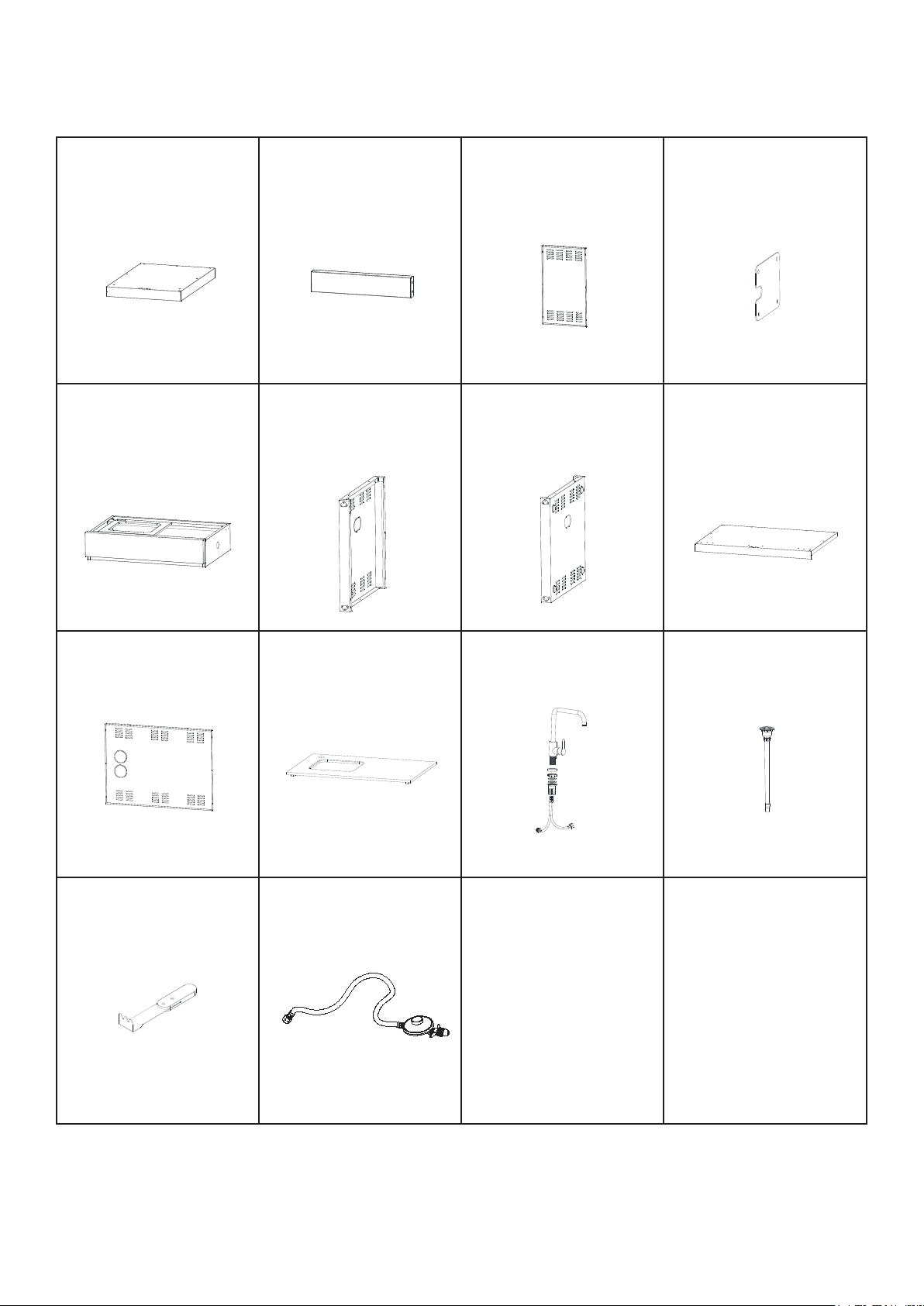
18 Side panel support of
cabinet x 2
19 Magnet plate
20 Castor without lock x
2
26 Smoker box
27 Grease cup
28 Handle of hood
30 Left door hinge -Upper
31 Left door hinge
-Down
32 Right door hinge
-Upper
1 Cooking grill x 2
2 Hotplate
3 Warming rack
4 Firebox
5 Flame tamer x2
6 Left side table
7 Right side burner
table
8 Side burner trivet
9 Regulator 10 Left side panel of
cabinet
11 Crossbeam
12 Bottom panel of
cabinet
PARTS LIST
cabinet
34 Crossbeam of right side
cabinet
35 Back panel of
right side cabinet
36 Fixed plate of regulator
cabinet
34 Crossbeam of right side
cabinet
35 Back panel of
right side cabinet
36 Fixed plate of regulator
38 Left side panel of left
side cabinet
39 Right side panel
of left side cabinet
40 Bottom panel of left
side cabinet
cabinet
42 Granite table
43 Tap
44 Water pipe
36 Fixed plate of regulator
40 Bottom panel of left
side cabinet
36 Fixed plate of regulator
cabinet
35 Back panel of
right side cabinet
36 Fixed plate of regulator
cabinet
34 Crossbeam of right side
cabinet
35 Back panel of
right side cabinet
36 Fixed plate of regulator
37 Left side table
38 Left side panel of left
side cabinet
39 Right side panel
of left side cabinet
40 Bottom panel of left
side cabinet
side cabinet
cabinet
35 Back panel of
right side cabinet
36 Fixed plate of regulator
39 Right side panel
of left side cabinet
40 Bottom panel of left
side cabinet
cabinet
35 Back panel of
right side cabinet
36 Fixed plate of regulator
side cabinet
39 Right side panel
of left side cabinet
40 Bottom panel of left
side cabinet
42 Granite table
43 Tap
44 Water pipe
43 Tap 44 Water pipe
33. Bottom panel
of right side
34. Crossbeam of
right side cabinet
cabinet
37. Left side table 38. Left side panel
of left side cabinet
35. Back panel of
right side cabinet
39. Right side
panel of left side
cabinet
36. Fixed regulator
plate
40. Bottom panel
of left side cabinet
41. Back panel of
42. Granite table 43. Tap 44. Water pipe
left side cabinet
45. Scraper tool 46. Regulator set
MATADOR INSTRUCTION MANUAL 11
Page 12
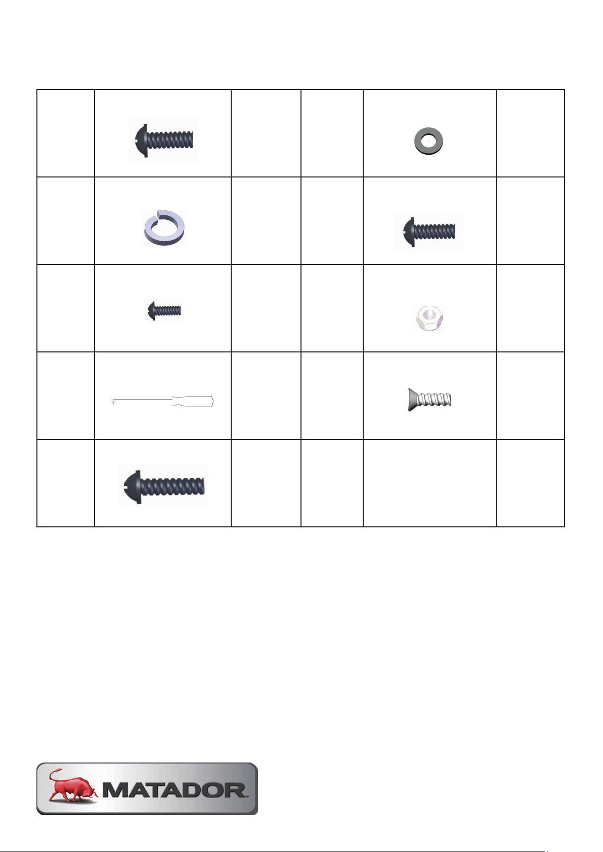
HARDWARE PACK
Bolt:M6*12
60 B
Washer:M6
18
Washer:M6
18
Bolt:M5*10
2
18
Bolt:M5*10
2
Nut:M4
3
Bolt:M4*10
12
18
2
3
Washer:M6
18
Bolt:M6*12
60 B
Washer:M6
18
18 D
Bolt:M5*10
2
Bolt:M10*8
5 F
Nut:M4
3
Screwdriver
1 H
Bolt:M4*10
12
Bolt:M6*35
2 J
Nut:M6
2
Bolt:M6*12
60 B
Washer:M6
18
Spring washer:M6
18 D
Bolt:M5*10
2
Bolt:M10*8
5 F
Nut:M4
3
Screwdriver
1 H
Bolt:M4*10
12
60 B
Washer:M6
18
18 D
Bolt:M5*10
2
5 F
Nut:M4
3
Bolt:M6*12
60 B
Washer:M6
18
18 D
Bolt:M5*10
2
A
C
E
Bolt: M6*12
Spring Washer: M6
Bolt: M4*12
Screwdriver
146 B
48 D
15 F
Washer: M6
48
Bolt: M5*10
2
Nut: M4
9
Bolt: M4*10
G
1 H
30
Bolt: M6*25
I
8
Page 13
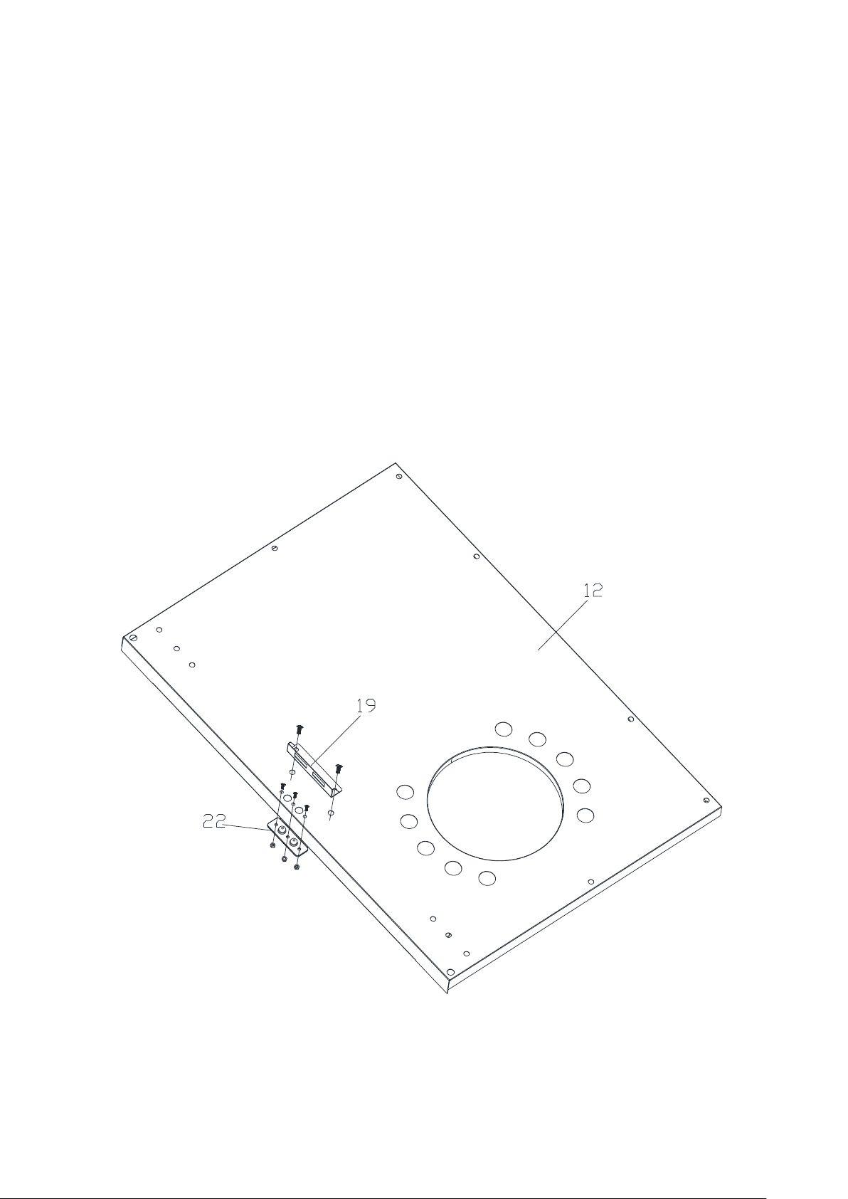
ASSEMBLY STEPS
Remove all packaging and transit protection materials from parts before assembly.
Wear gloves during assembly to protect your hands from cuts and abrasions.
Some stages of assembly require a 2 person lift.
STEP 1
Assemble the door magnet panel (19) on the bottom cabinet panel (12) by screw
(A) 2pcs as shown.
Assemble the plastic backing board (22) on the bottom cabinet panel (12) by screw
(E) 3pcs and Nut (F) 3pcs as shown.
MATADOR INSTRUCTION MANUAL 13
Page 14
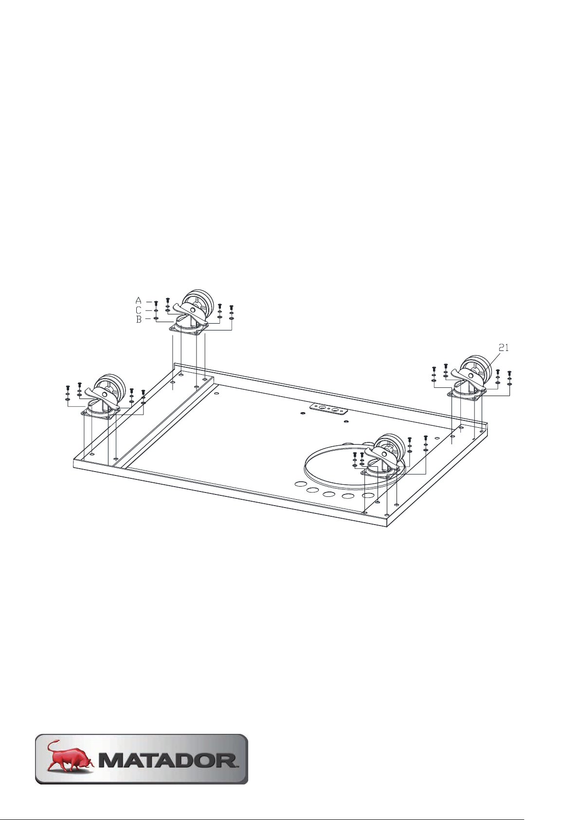
STEP 2
SSTTEEPP 22
Assemble the castor with lock (21) on the bottom panel of cabinet (12) by bolt(A), spring
washer (C), washer (B) each 16pcs as shown
Assemble the castor with lock (21) on the bottom cabinet panel (12) by bolt (A),
spring washer (C), washer (B) each 16pcs as shown.
Page 15
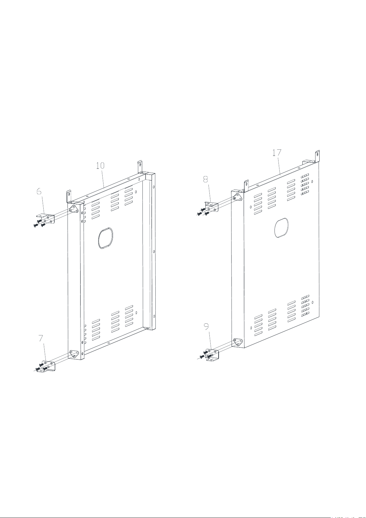
SSTTEEPP 33
Assemble left door hinge-Upper (6) and left door hinge-Down(7) on the left side panel of cabinet
(10) and assemble right door hinge-Upper (8) and right door hinge-Down (9) on the right side
panel of cabinet (17) by bolt (H) 12pcs.
STEP 3
Assemble left door hinge - upper (6) and left door hinge - lower (7) on the left side
cabinet panel (10) and assemble right door hinge - upper (8) and right door hinge lower (9) on the right side cabinet panel (17) by bolt (H) 12pcs.
MATADOR INSTRUCTION MANUAL 15
Page 16
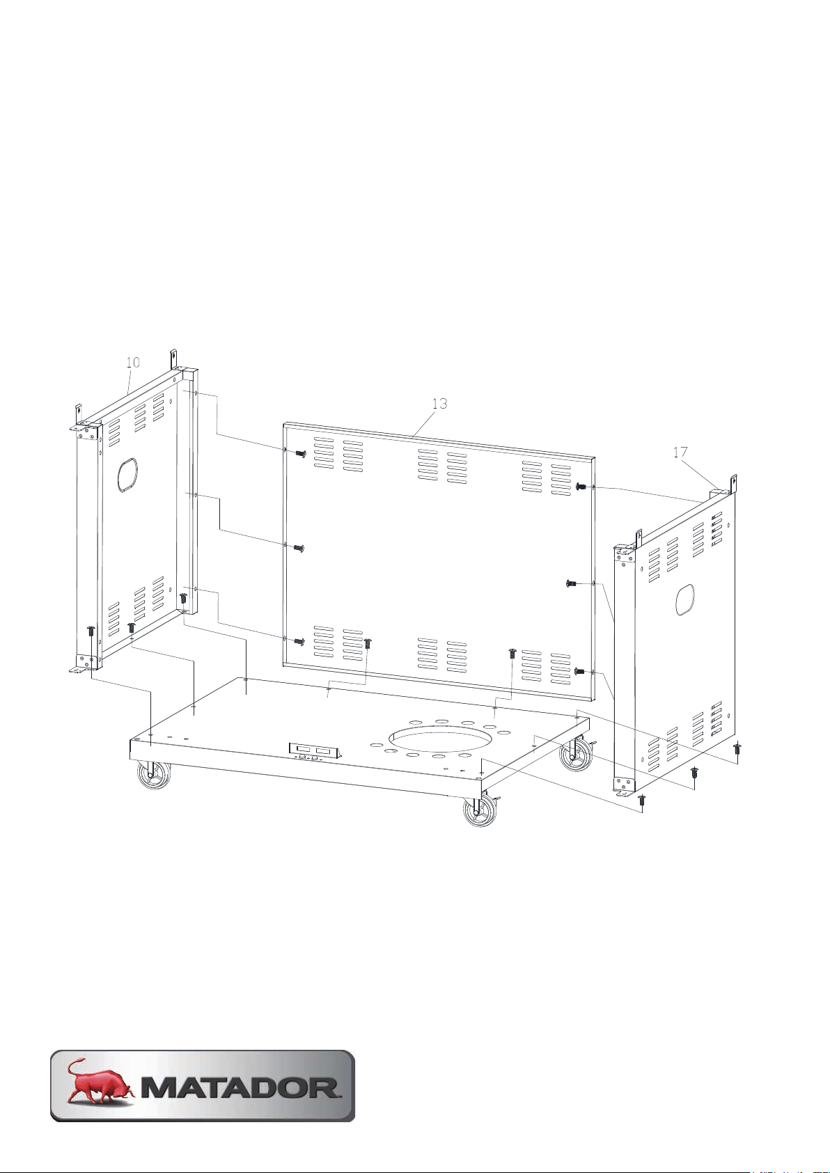
SSTTEEPP 44
Assemble left side panel of main cabinet (10), back panel of cabinet (13) and right side panel of
main cabinet (17) on the bottom panel of cabinet (12) by blot (A) 14pcs as shown.
STEP 4
Assemble left side of main cabinet panel (10), back cabinet panel (13) and right
side of main cabinet panel (17) on the bottom cabinet panel (12) by bolt (A) 14pcs
as shown.
Page 17
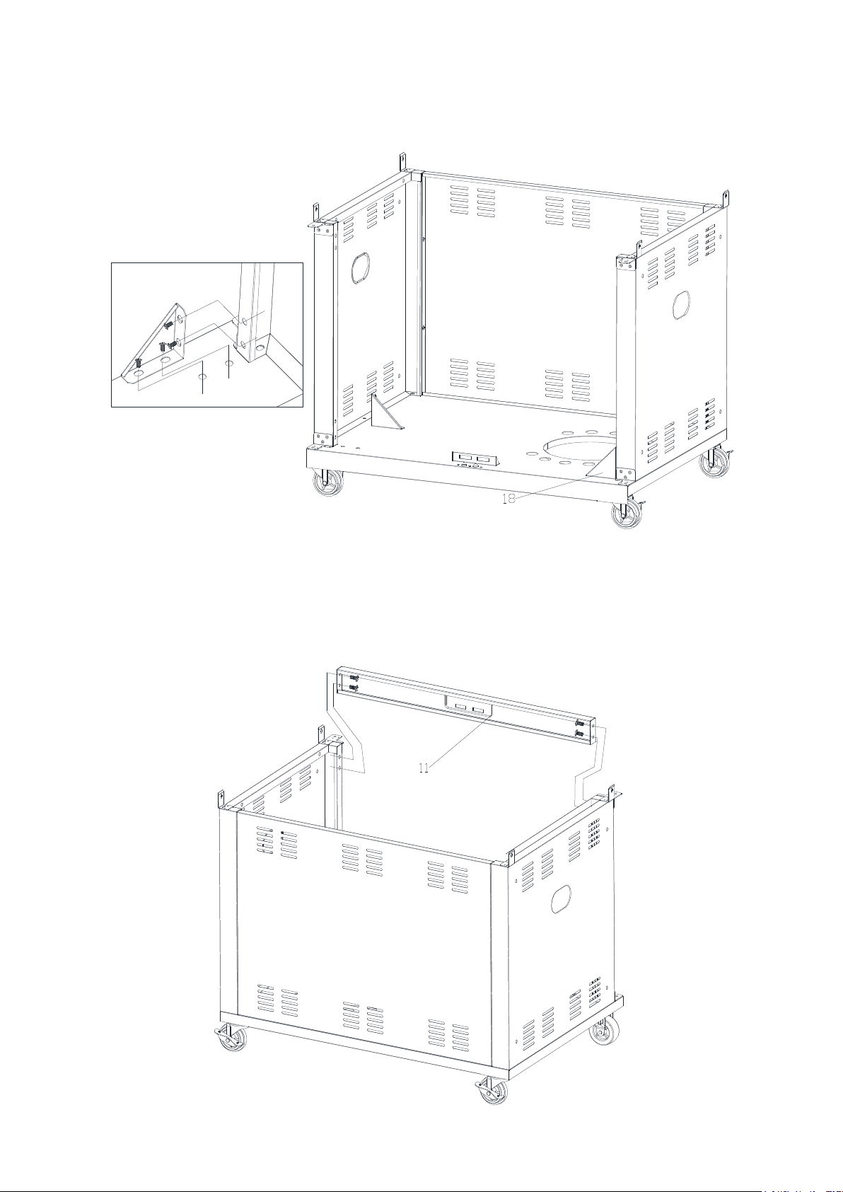
SSTTEEPP 55
Assemble side panel support of cabinet (18) on the bottom panel by bolt (A) 8pcs as shown.
SSTTEEPP 66
Assemble crossbeam (11) on the cabinet by bolt (A) 4pcs as shown.
STEP 5
SSTTEEPP 55
Assemble side panel support of cabinet (18) on the bottom panel by bolt (A) 8pcs as shown.
Assemble side cabinet panel support (18) on the bottom panel by bolt (A) 8pcs as
shown.
STEP 6
Assemble crossbeam (11) on the cabinet by bolt (A) 4pcs as shown.
MATADOR INSTRUCTION MANUAL 17
Page 18
STEP 7
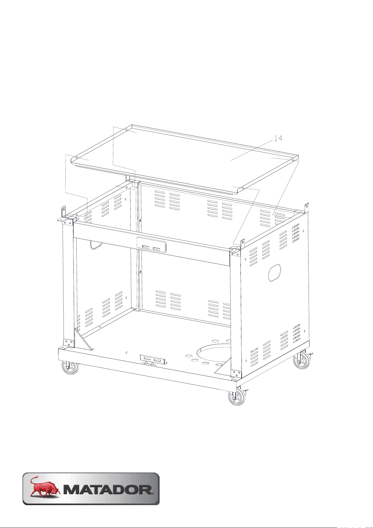
Assemble cabinet separation panel (14) on the cabinet by bolt (A) 4pcs as shown.
Page 19
SSTTEEPP 88
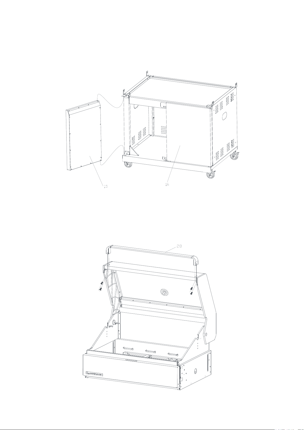
Assemble left door (15) and right door (16) on the cabinet as shown. First position the lower
fixed locating PIN and then depress upper spring loaded PIN and move door into position.
SSTTEEPP 99
Assemble handle of hood (28) on the hood by bolt (A) 4pcs as shown.
STEP 8
SSTTEEPP 88
Assemble left door (15) and right door (16) on the cabinet as shown. First position the lower
fixed locating PIN and then depress upper spring loaded PIN and move door into position.
Assemble left door (15) and right door (16) on the cabinet as shown.
STEP 9
Assemble handle of hood (28) on the hood by bolt (A) 4pcs as shown.
MATADOR INSTRUCTION MANUAL 19
Page 20
SSTTEEPP 1100
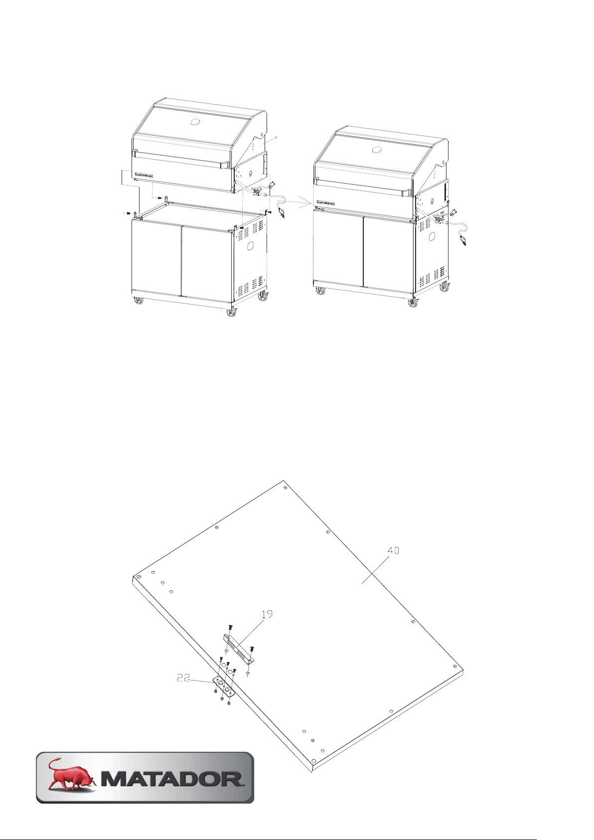
Assemble firebox (4) on the cabinet by bolt (A) 4pcs as shown.
SSTTEEPP 1111
Assemble the door magnet panel (19) on the bottom panel of left side cabinet (40) by bolt(A)
2pcs as shown.
Assemble the plastic backing board (22) on the bottom panel of left cabinet (40) by bolt (E) 3pcs
and Nut (F) 3pcs as shown.
STEP 10
SSTTEEPP 1100
Assemble firebox (4) on the cabinet by bolt (A) 4pcs as shown.
Assemble firebox (4) on the cabinet by bolt (A) 4pcs as shown.
STEP 11
Assemble the door magnet panel (19) on the bottom panel of left side cabinet (40)
by bolt (A)2pcs as shown.
Assemble the plastic backing board (22) on the bottom panel of left cabinet (40) by
bolt (E) 3pcs and Nut (F) 3pcs as shown.
Page 21
SSTTEEPP 1122
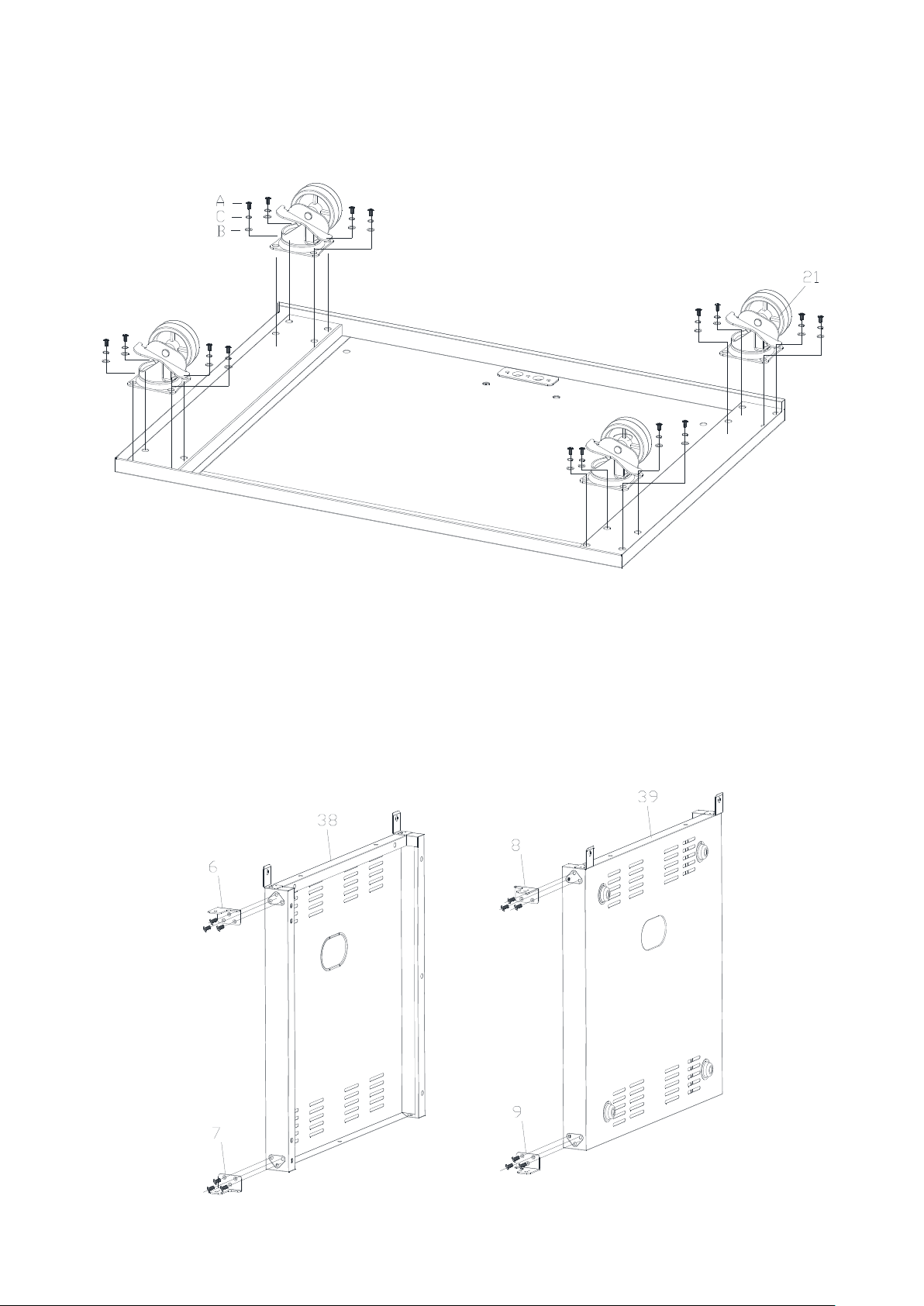
Assemble the castor with lock (21) on the bottom panel of left side cabinet (40) by bolt(A),
spring washer (C), washer (B) each 16pcs as shown.
SSTTEEPP 1133
Assemble left door hinge-Upper (6) and left door hinge-Down(7) on the left side panel of left side
cabinet (38) and assemble right door hinge-Upper (8) and right door hinge-Down (9) on the right
side panel of left cabinet (17) by bolt (H) 12pcs.
STEP 12
SSTTEEPP 1122
Assemble the castor with lock (21) on the bottom panel of left side cabinet (40) by bolt(A),
spring washer (C), washer (B) each 16pcs as shown.
Assemble the castor with lock (21) on the bottom panel of left side cabinet (40) by
bolt (A), spring washer (C), washer (B) each 16pcs as shown.
STEP 13
Assemble left door hinge-upper (6) and left door hinge-lower (7) on the left side
panel of left side cabinet (38) and assemble right door hinge-Upper (8) and right
door hinge-lower (9) on the right side panel of left cabinet (17) by bolt (H) 12pcs.
MATADOR INSTRUCTION MANUAL 21
Page 22
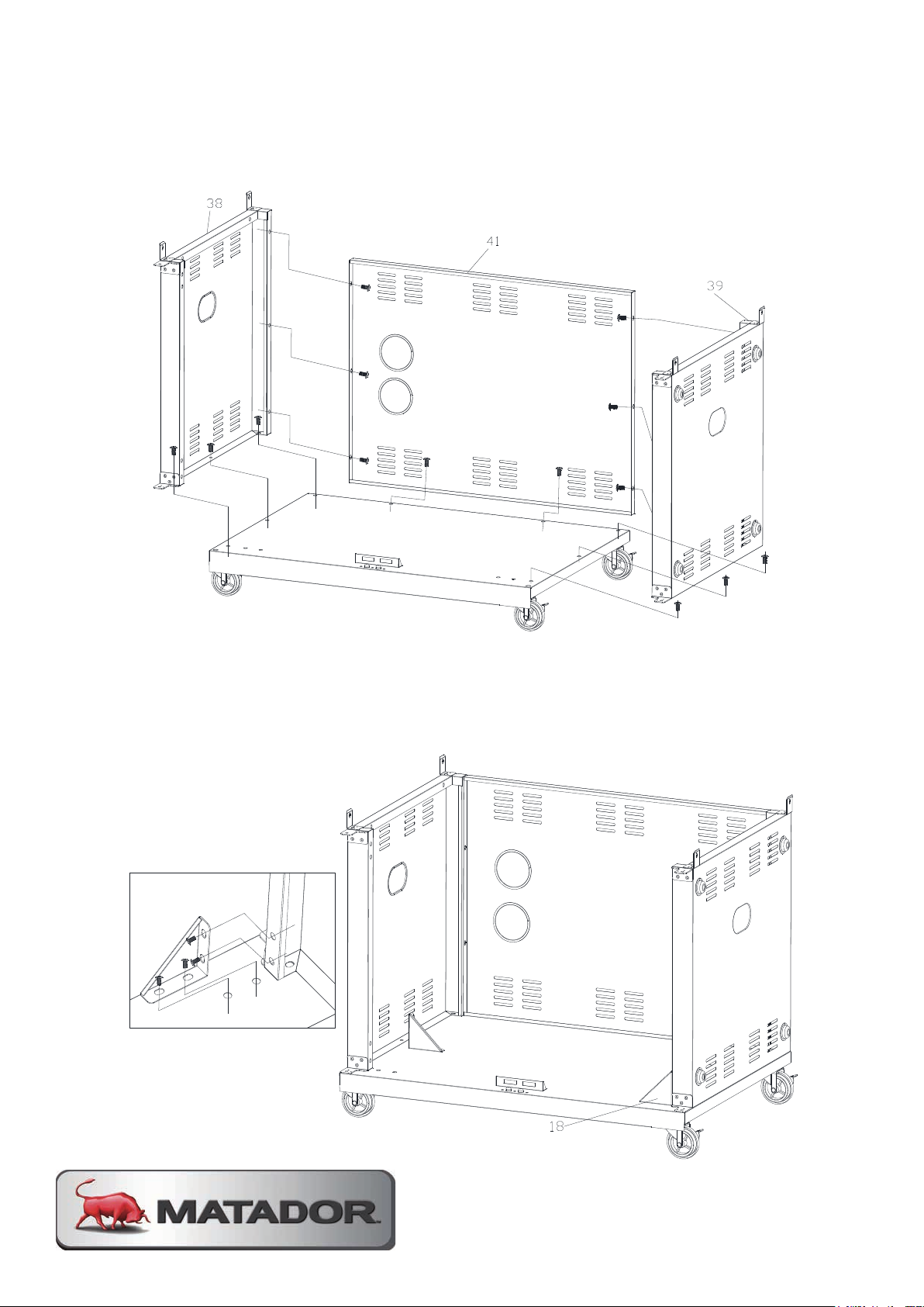
SSTTEEPP 1144
Assemble left side panel of left side cabinet (38), back panel of left side cabinet (41) and right
side panel of left cabinet (39) on the bottom panel of left cabinet (40) by bolt (A) 14pcs as shown.
SSTTEEPP 1155
Assemble side panel support of cabinet (18) on the bottom panel of left side cabinet (40) by bolt
(A) 8pcs as shown.
STEP 14
SSTTEEPP 1144
Assemble left side panel of left side cabinet (38), back panel of left side cabinet (41) and right
side panel of left cabinet (39) on the bottom panel of left cabinet (40) by bolt (A) 14pcs as shown.
Assemble left side panel of left side cabinet (38), back panel of left side cabinet
(41) and right side panel of left cabinet (39) on the bottom panel of left cabinet (40)
by bolt (A) 14pcs as shown.
STEP 15
Assemble side cabinet panel support (18) on the bottom panel of left side cabinet
(40) by bolt (A) 8pcs as shown.
Page 23
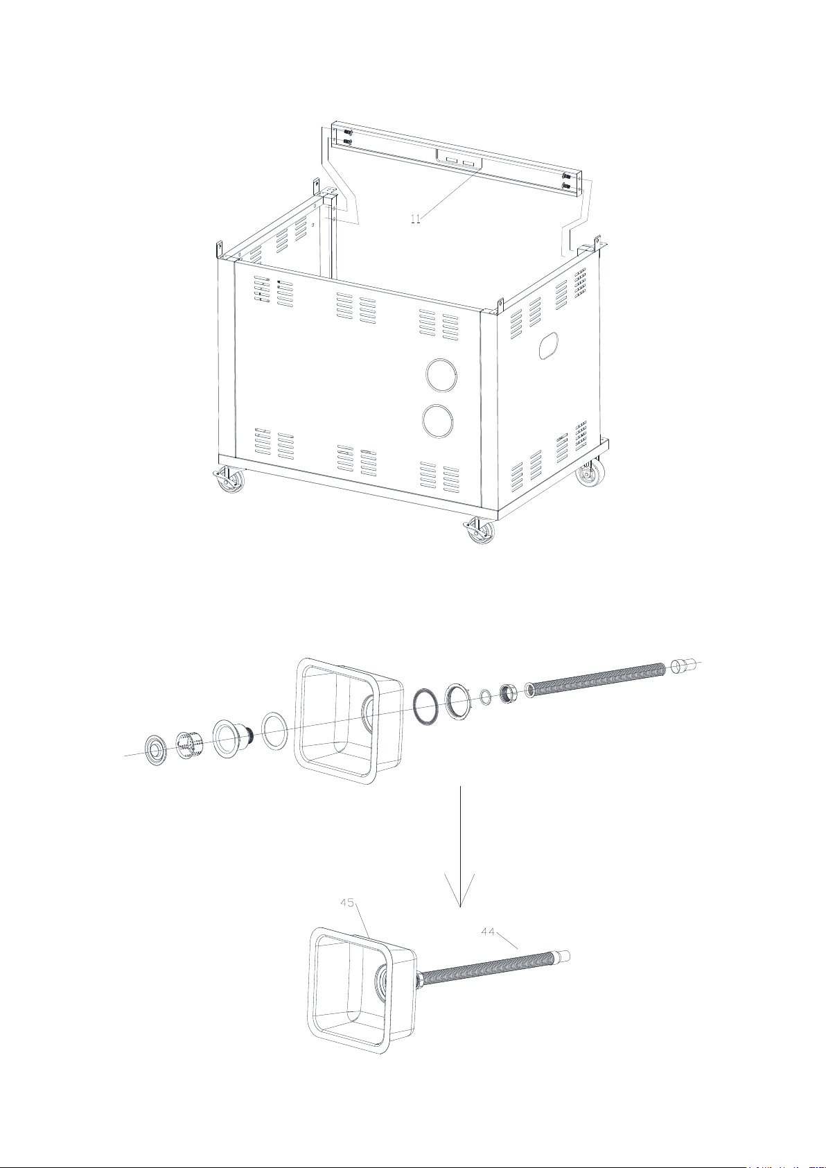
SSTTEEPP 1166
Assemble crossbeam (11) on the left side cabinet by bolt (A) 4pcs as shown.
SSTTEEPP 1177
Assemble the water pipe (44) on the sink as shown.
STEP 16
SSTTEEPP 1166
Assemble crossbeam (11) on the left side cabinet by bolt (A) 4pcs as shown.
Assemble crossbeam (11) on the left side cabinet by bolt (A) 4pcs as shown.
STEP 17
Assemble the water pipe (44) on the sink as shown.
MATADOR INSTRUCTION MANUAL 23
Page 24
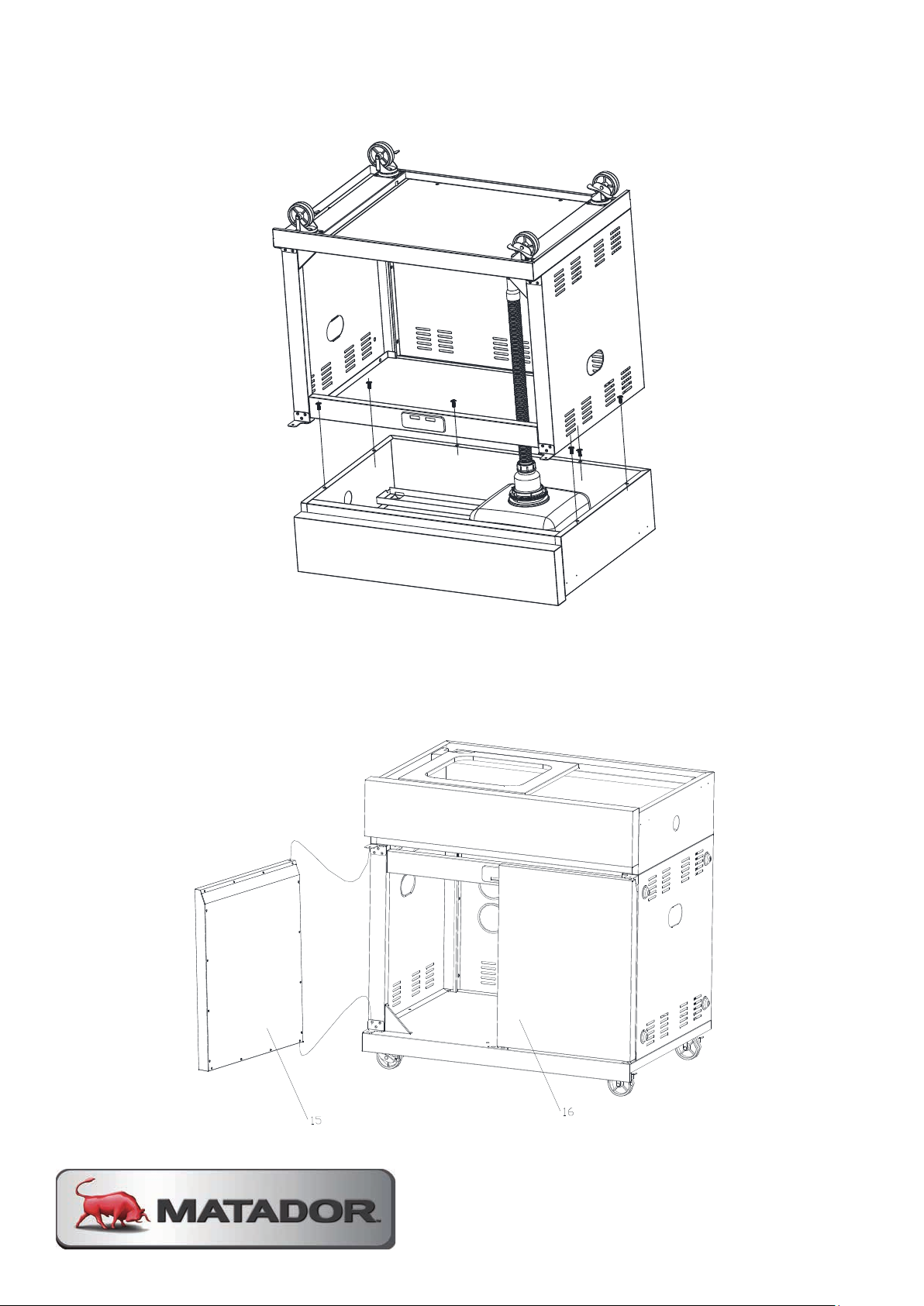
STEP 18
STEP 19
Assemble the left door(15) and right door (16) on the cabinet as shown.
STEP 17
Assemble the water pipe (44) on the sink as shown.
STEP 18
Assemble the left side table (37) on the left side cabinet by bolt (A) 6pcs as shown.
Assemble the left side table (37) on the left side cabinet by bolt (A) 6pcs as shown.
STEP 19
Assemble the left door(15) and right door (16) on the cabinet as shown.
Page 25
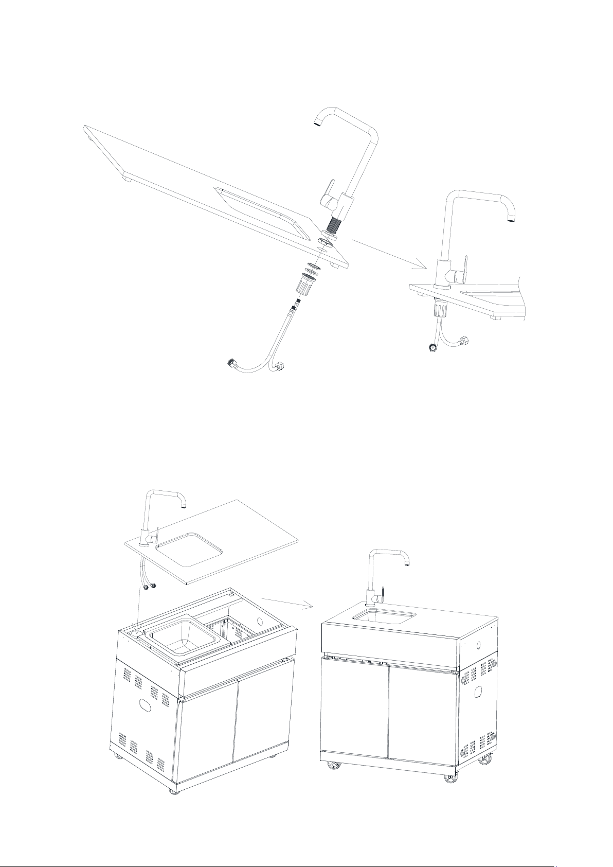
STEP 20
STEP 21
Assemble the granite table and Sink on the cabinet as shown.
Assemble the tap (43) on the granite table (42) as shown.
STEP 21
Assemble the granite table and sink on the cabinet as shown.
MATADOR INSTRUCTION MANUAL 25
Page 26
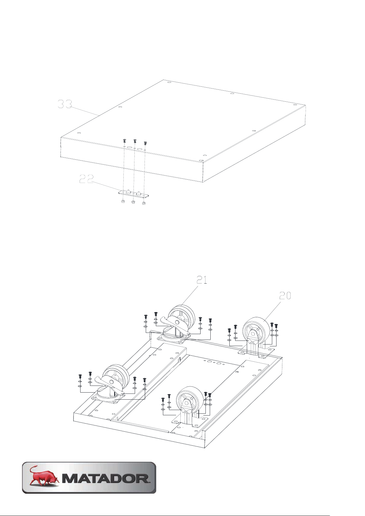
SSTTEEPP 2222
Assemble the plastic backing board (22) on the bottom panel of right side cabinet (33) by bolt (E)
3pcs and Nut (F) 3pcs as shown.
SSTTEEPP 2233
Assemble the castor without lock (20) and castor with lock (21) on the bottom panel of right side
cabinet (33) by bolt(A), spring washer (C), washer (B) each 16pcs as shown.
STEP 22
SSTTEEPP 2222
Assemble the plastic backing board (22) on the bottom panel of right side cabinet (33) by bolt (E)
3pcs and Nut (F) 3pcs as shown.
Assemble the plastic backing board (22) on the bottom panel of right side cabinet
(33) by bolt (E) 3pcs and nut (F) 3pcs as shown.
STEP 23
Assemble the castor without lock (20) and castor with lock (21) on the bottom
panel of right side cabinet (33) by bolt (A), spring washer (C), washer (B) each
16pcs as shown.
Page 27
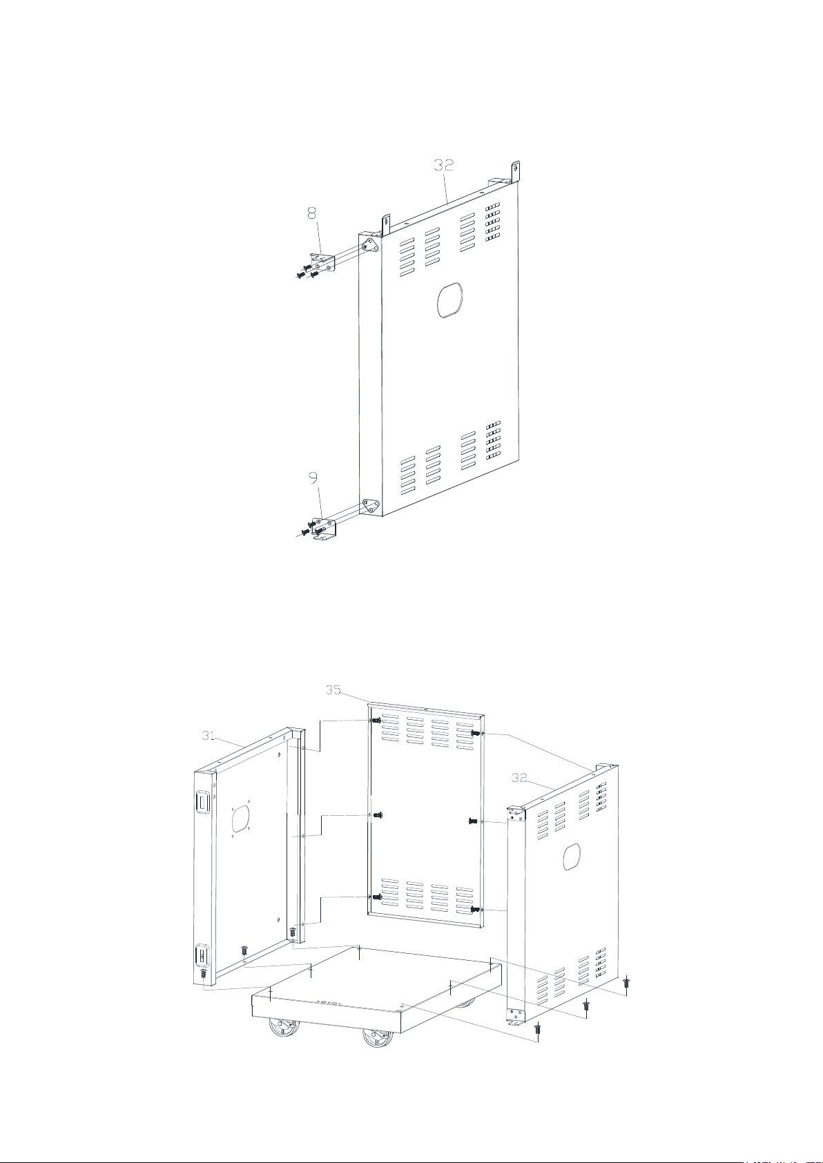
STEP 24
SSTTEEPP 2244
Assemble right door hinge-Upper (8) and right door hinge-Down (9) on the right side panel of
right cabinet (32) by bolt (H) 6pcs.
Assemble right door hinge-upper (8) and right door hinge-lower (9) on the right side
panel of right cabinet (32) by bolt (H) 6pcs.
STEP 25
Assemble left side panel of right side cabinet (31), back panel of right side cabinet
(35) and right side panel of right cabinet (32) on the bottom panel of right cabinet
(33) by bolt (A) 14pcs as shown.
MATADOR INSTRUCTION MANUAL 27
Page 28
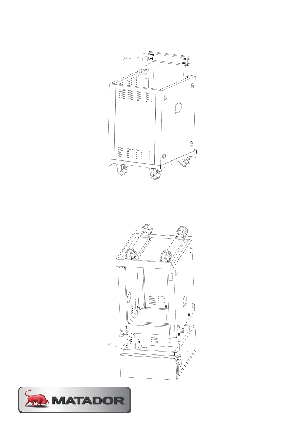
SSTTEEPP 2266
Assemble crossbeam (34) on the right side cabinet by bolt (A) 4pcs as shown.
SSTTEEPP 2277
Assemble the right side burner table (30) on the right side cabinet by bolt (A) 5pcs as shown.
STEP 26
SSTTEEPP 2266
Assemble crossbeam (34) on the right side cabinet by bolt (A) 4pcs as shown.
Assemble crossbeam (34) on the right side cabinet by bolt (A) 4pcs as shown.
STEP 27
Assemble the right side burner table (30) on the right side cabinet by bolt (A) 5pcs
as shown.
Page 29
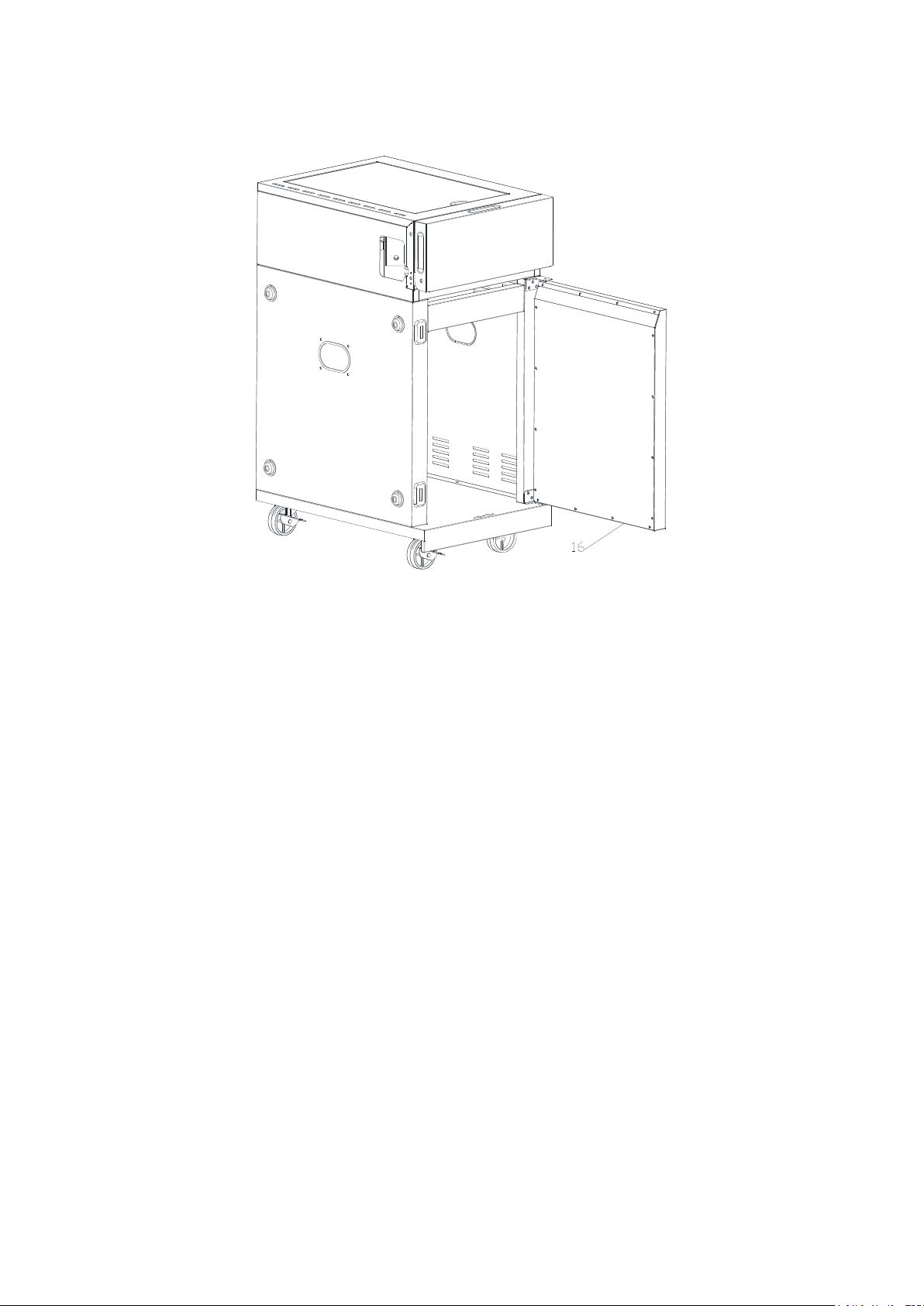
SSTTEEPP 1177
Assemble the right door (16) on the right side cabinet as shown.
STEP 28
Assemble the right door (16) on the right side cabinet as shown.
MATADOR INSTRUCTION MANUAL 29
Page 30
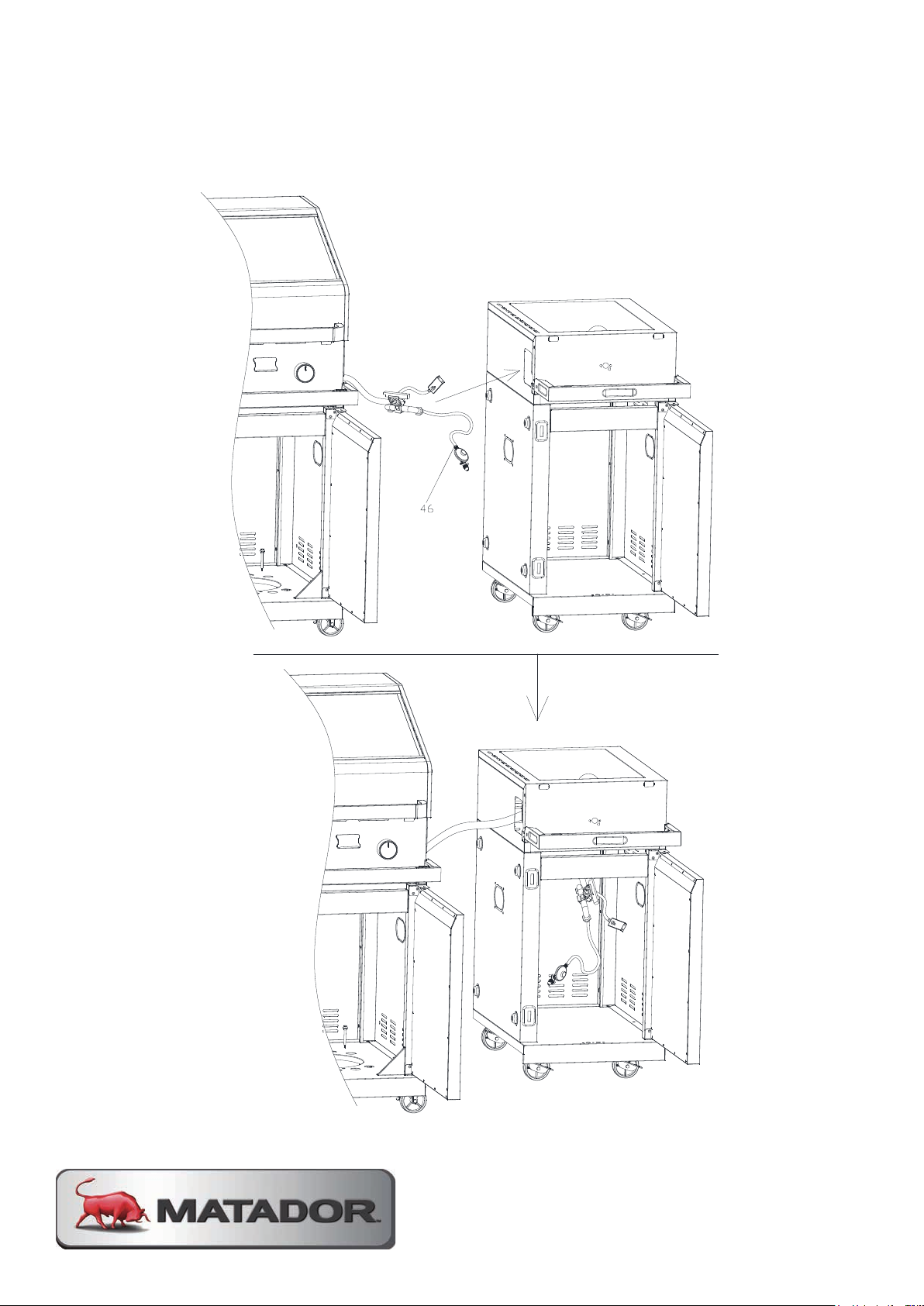
SSTTEEPP 2299
Put the regulator and side valve into right side cabinet square hole as below shown.
STEP 29
Put the regulator and side valve into right side cabinet square hole as below
shown.
Page 31
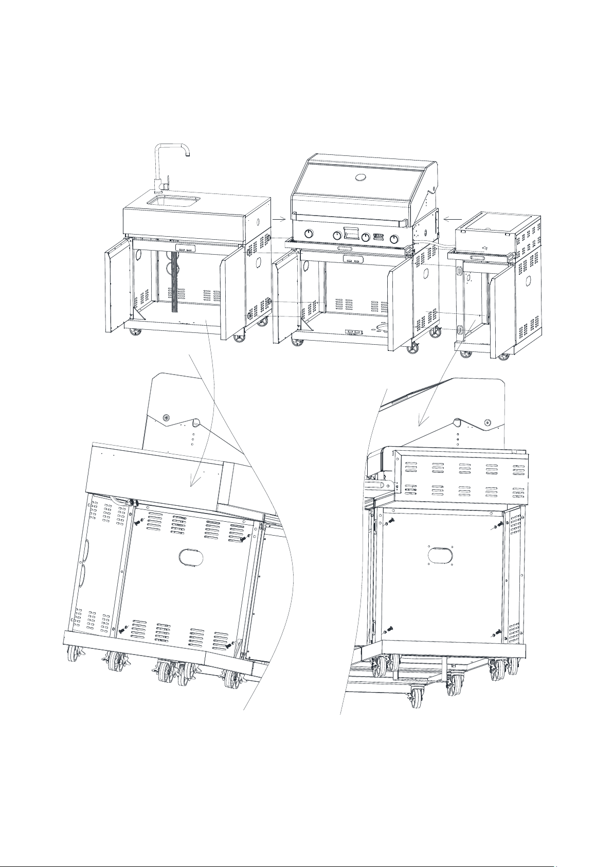
STEP 30
Assemble the left side cabinet and main body and right side cabinet by bolt (I)
8pcs as shown.
MATADOR INSTRUCTION MANUAL 31
Page 32
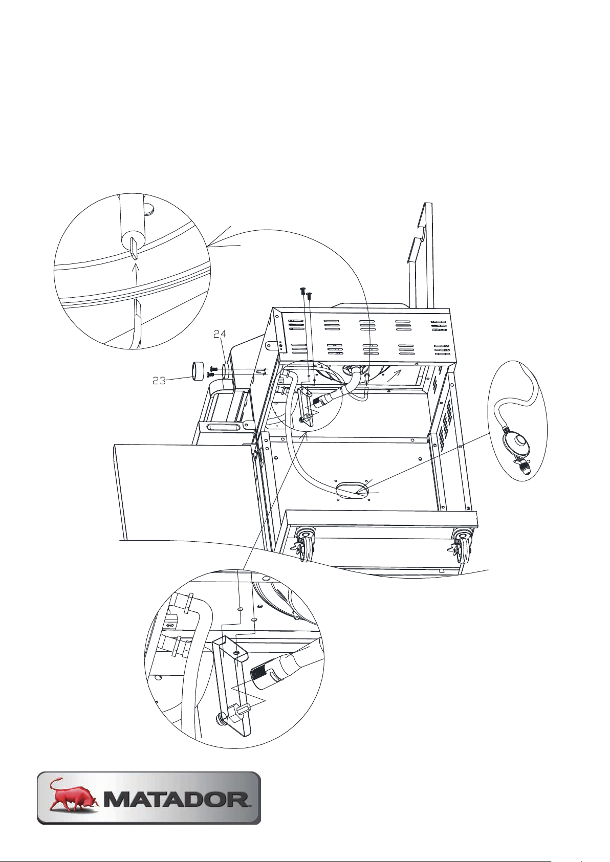
STEP 31
Assemble control knob seat (24) on the side valve by bolt (E) 2pcs as shown, put
the control knob (23) on the valve bar as shown.
Insert the ignition wire as shown and put the regulator to main body cabinet from
oval hole as shown.
Assemble the injector bracket by screw (D) 2pcs as photo A and B shown.
Page 33
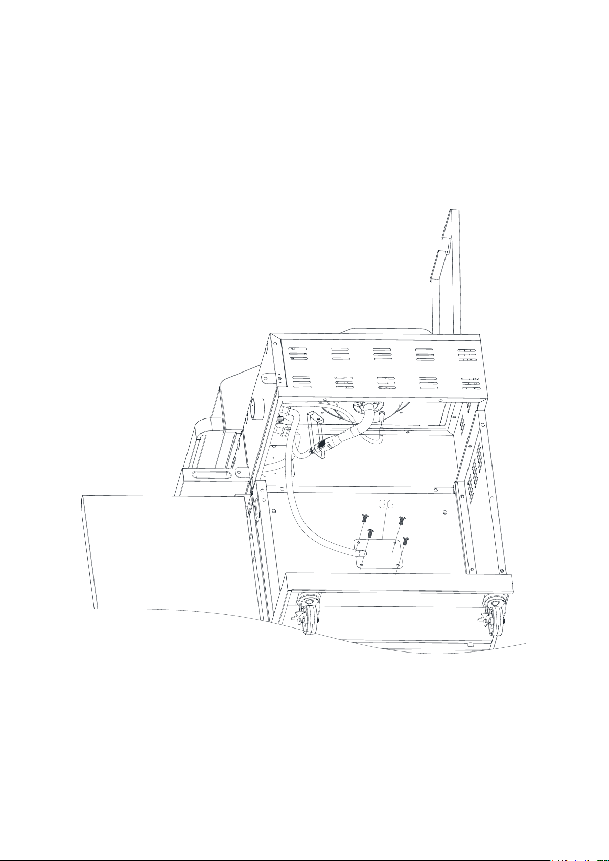
STEP 32
Assemble the fixed regulator plate (36) on the right side cabinet by bolt (E) 4pcs as
shown.
MATADOR INSTRUCTION MANUAL 33
Page 34
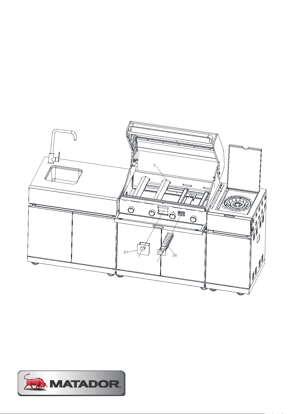
STEP 33
Assemble the fixed plate of regulator (36) on the right side cabinet by bolt (E) 4pcs as shown.
STEP 33
Insert the grease cup (27) and smoker box (26) on the control panel and insert the flame tamer (5) into the
firebox as shown.
Insert the grease cup (27) and smoker box (26) on the control panel and insert the
flame tamer (5) into the firebox as shown.
Page 35
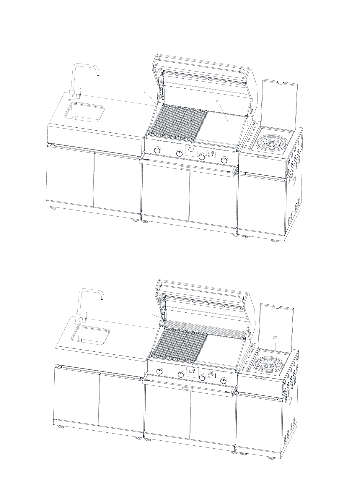
STEP 34
STEP 35
Insert the warming rack(3)and side burner trivet (29) as shown.
Insert the cooking grill (1) and hotplate (2) on the firebox as shown.
STEP 35
Insert the warming rack (3) and side burner trivet (29) as shown.
MATADOR INSTRUCTION MANUAL 35
Page 36
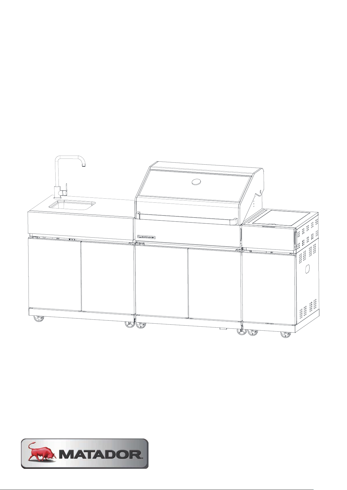
FULLY ASSEMBLED BBQ
Page 37

BBQ LOCATION OUTDOOR AREAS
This appliance shall only be used in an above ground open-air situation with
natural ventilation, without stagnant areas, where gas leakage and products of
combustion are rapidly dispersed by wind and natural convection.
Any enclosure in which the appliance is used shall comply with one of the
following:
-
An enclosure with walls on all sides, but at least one permanent opening at
ground level and no overhead cover.
-
Within a partial enclosure that includes an overhead cover and no more than two
walls.
-
At least 25% of the total wall area is completely open; and
-
At least 30% of the remaining wall area is open and unrestricted.
-
In the case of balconies, at least 20% of the total of the side, back and front wall
areas shall be and remain open and unrestricted.
Examples of the correct appliance outdoor setups can be seen below.
OUTDOOR AREA
EXAMPLE 1
MATADOR INSTRUCTION MANUAL 37
Page 38
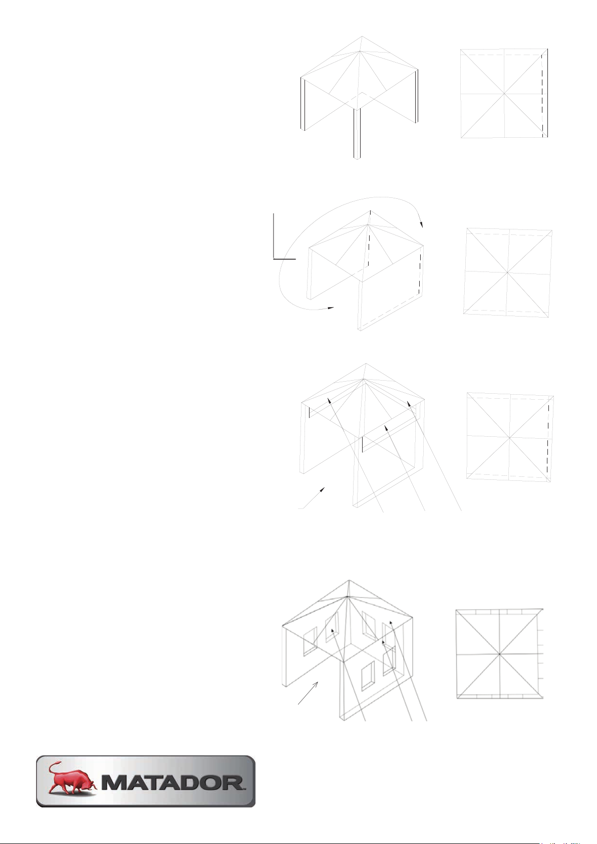
30% or more in total of the remaining
wall area is open and unrestricted
OUTDOOR AREA
EXAMPLE 2
OUTDOOR AREA
EXAMPLE 3
Both ends open
OUTDOOR AREA
EXAMPLE 4
Open sides are at least 25% of total wall area
OUTDOOR AREA
EXAMPLE 5
Open sides are at least 25% of total wall area
30% or more in total of the remaining wall
area is open and unrestricted
00
30% or more in total of the remaining wall
area is open and unrestricted
Page 39
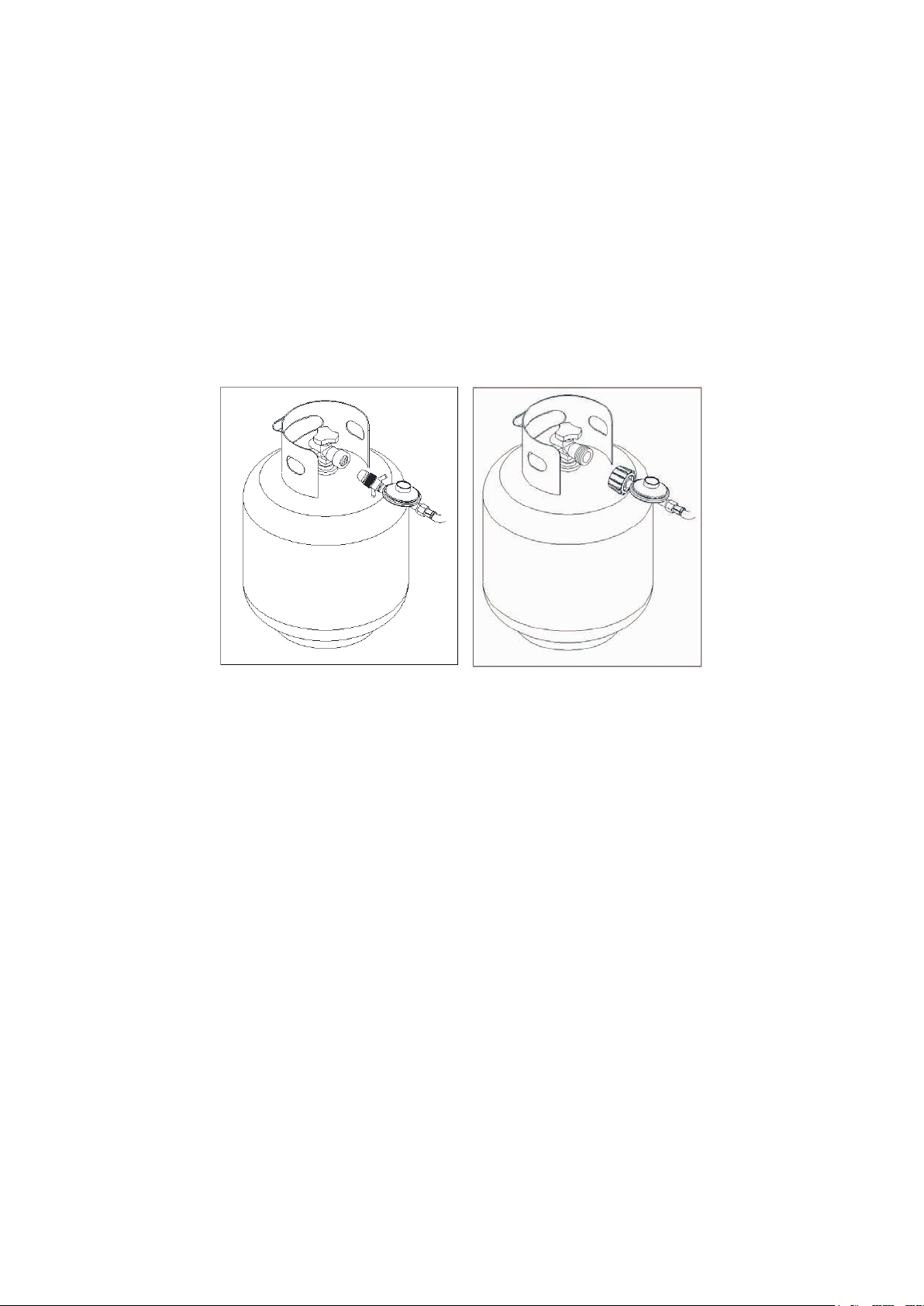
CONNECTION TO LPG
GAS LEAK TESTING
Gas leak testing, mentioned earlier in the manual, must be done the first time you
connect up the BBQ, and whenever the LPG cylinder is re-connected to the BBQ.
Always inspect the hose at regular intervals to check for cracks or abrasion.
CONNECTING THE LPG CYLINDER
Connect the regulator to the LPG cylinder and tighten the connection. The two
1.
types of connections can be seen below.
POL
Turn the gas on at the cylinder, or make sure gas is available to the BBQ, but
2.
do not turn the burners on. This fills the gas lines with gas. Now brush or pour
some soapy water onto all connections. If there is a leak, bubbles should appear
within about 20 seconds. If you find any leaks, tighten the connection and
repeat the leak test. If the leaks persist, contact your place of purchase.
WARNINGS
DO NOT USE NAKED FLAME FOR LOCATING GAS LEAKS
IF A LEAK PERSISTS, CALL AND AUTHORISED PERSON
DO NOT USE THIS BBQ UNLESS ALL CONNECTIONS ARE GASTIGHT
In the case of a problem arising with the hose and regulator please contact your
BBQ supplier for a list of approved replacement parts.
QCC
MATADOR INSTRUCTION MANUAL 39
Page 40

LIGHTING PROCEDURE
BEFORE STARTING
Lighting the BBQ is easy, but must be done with due care.
Make sure the LPG cylinder is filled.
Make sure that gas is turned on at the cylinder, or that gas is available to the
BBQ.
Check that the end of each burner tube is properly located over each valve
orifice.
Make sure all gas connections are securely tightened.
Open the hood or side burner lid.
-
TYPES OF IGNITION
MANUAL IGNITION (in case of lighting failure from BBQ ignition)
With the hood or side burner lid open, place a lit match or long stem gas lighter
close to the burner you wish to light. Be cautious of the position of your hand
and ensure it remains a reasonable distance from the burner. Turn the control to
the “High” position. The burner should light. If it fails to light, return the control to
the “OFF” position and try again in five minutes.
FLAME THROWER IGNITION OF BBQ BURNERS
The BBQ burners are equipped with automatic ignition. It works by throwing a
flame to the side of the burner to light. Push the knob in and turn anticlockwise
to the high position. You should hear and feel a click from the knob. Hold the
knob in and observe the flame extend towards the side of the burner. When the
burner ignites, release the control knob. If the burner doesn’t light on the first
attempt, return the knob to the “OFF” position and try several more times. If the
burner still does not light, wait a few minutes to allow the gas to disperse before
trying again.
SIDE BURNER IGNITION
The side burner incorporates an electrode next to the side burner. To light the
side burner, simply push the side burner knob in and turn anticlockwise to the
high position. You should hear and feel a click from the knob. When the burner
ignites, release the control knob. If the burner doesn’t light on the first attempt,
return the knob to the “OFF” position and try several more times. If the burner
still does not light, wait a few minutes to allow the gas to disperse before trying
again.
Page 41
USING THE BBQ
CONTROLLING THE FLAMES
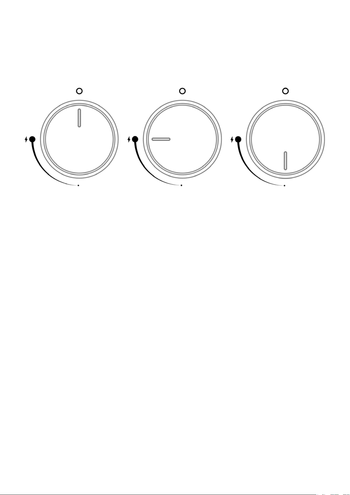
The knobs have three basic positions. You can achieve any flame height between
low and high by rotating the knob between these positions.
OFF HIGH LOW
NOTE: ‘Light back’ is a situation where the flame burns inside the burner,
towards the front, recognized by a sharp roaring sound coming from the burner.
It is not dangerous unless allowed to persist. If this occurs, simply turn the
burner off, wait a few minutes, and then relight.
COOKING FOR THE FIRST TIME
IMPORTANT: Please add sand or fat absorption granules to the grease tray
-
before first use.
We recommended you wash the cooking surfaces with soap and warm water
before use.
The cooking plates are vitreous enamel coated and they do not require seasoning
like most other BBQs.
MATADOR INSTRUCTION MANUAL 41
Page 42
USING THE SMOKER BOX
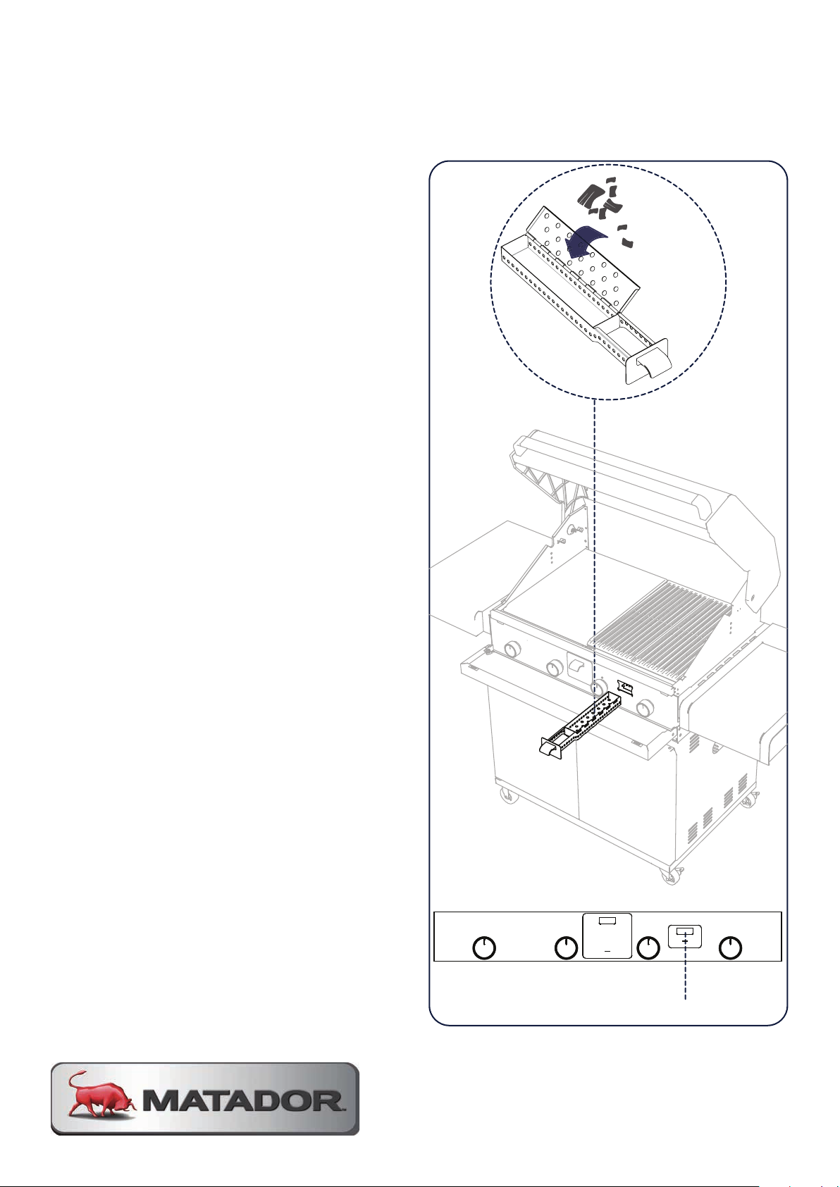
The following steps are guide to getting
good lasting smoke from the wood
chips in your smoker box.
1.
With the hood open and the burners
off, slide out the smoker box and fill
with your favourite wood chips.
Ensure the smoker box is not over
filled and the lid can close fully before
sliding back into the BBQ.
2.
Ignite burners 3 and 4 (seen in the
below image on either side of the
smoker box) and turn to a medium
setting. Ensure the hood of the BBQ
remains open during this step.
Leave on medium for approximately
10 - 15 minutes or until you see white
smoke wafting from the grill plates.
3.
When smoke has been achieved,
turn off burner 3, turn burner 4 to low
and turn on burner 1 to low. At this
stage, the lid of the BBQ can now be
closed and is ready for smoking your
favourite food.
You will receive approximately 20 - 25
minutes of smoke time. This depends
on the weather conditions and type of
wood chips used.
BURNERLOCATION
The smoker box can be refilled
at anytime. Be sure to use high
temperature gloves as the smoker box
will be very hot.
Smoker Box
Page 43
BBBBQQ TTIIPPSS
Before cooking, coat the hotplate with oil. This will prevent food from sticking. Open the hood
and light the burners to preheat the BBQ.
Avoid continually turning the meat over. When cooking internal juices rise to the surface of the
meat and then settle. Each time you turn the meat over, the juices are lost.
Keep the valleys in the cooking plate clear for fat and oils to flow to the grease collection cup at
the front of the BBQ. A scraper tool is provided to make this easy.
BBQ TIPS
Before cooking, coat the hotplate with oil. This will prevent food from sticking.
Open the hood and light the burners to preheat the BBQ.
Avoid continually turning the meat over. When cooking internal juices rise to the
surface of the meat and then settle. Each time you turn the meat over, the juices
are lost.
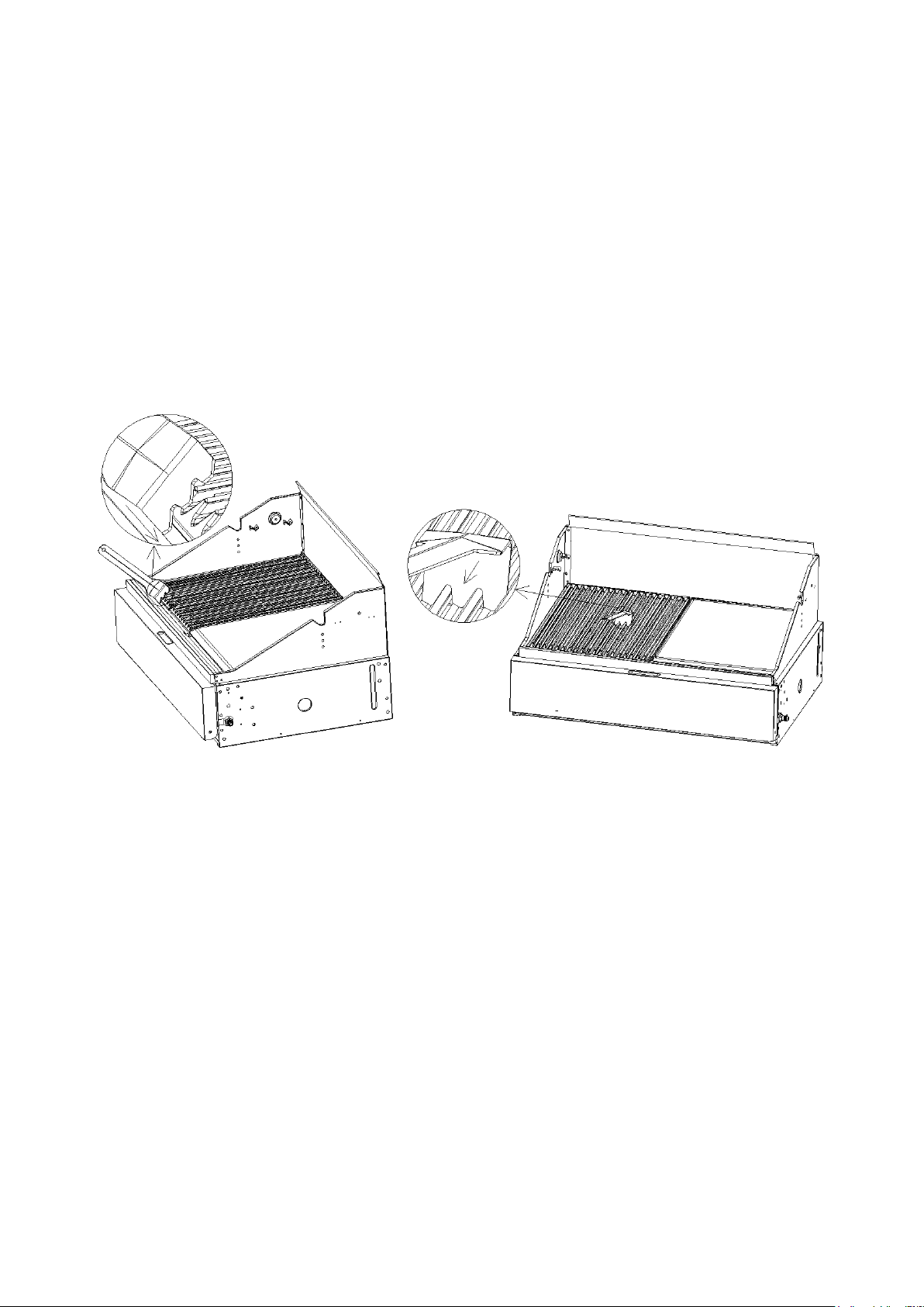
Keep the valleys in the cooking plate clear for fat and oils to flow to the grease
collection cup at the front of the BBQ. A scraper tool is provided to make this
easy. This can be seen below.
Oil does not flow uphill. If your BBQ is not correctly positioned, oil won’t flow
forward to the grease collection cup.
Avoid burning or charring food excessively and do not leave cooked food
standing for too long before eating.
The minimum size LPG cylinder recommended for this BBQ is 9kg The maximum
vessel size on the side burner is diameter 25cm
Check the Grease Cup before use to prevent overflow of grease.
AFTER USE
To turn the BBQ off, it is best to turn off the cylinder first, and allow all the gas
remaining in the hose to burn off, this will only take a couple of seconds. Then
turn off all burners. While the hotplate is still hot, take a long handled brush and
a scraper and remove remaining oil and food scraps. You should use protective
gloves to avoid burning yourself. Then re-coat the plate with oil for continued
protection.
MATADOR INSTRUCTION MANUAL 43
Page 44

BBQ MAINTENANCE
PPEERRIIOODDIICC CCLLEEAANNIINNGG
Your BBQ
You should check the burners periodically for any sort of blockage. To do this, remove and inspect
them. If any of the holes are clogged, gently tap the burner onto a hard surface to remove residue.
Use a wire brush to unclog the holes.
Grease can build up on the frame itself. Most of it can be cleaned off with hot water. Use a
non-caustic cleanser for more stubborn stains.
You should empty the fat / drip tray frequently. Never touch the fat / drip tr
at
have cooled down completely.
AA bbuuiilldd uupp ooff ggrreeaassee,, ffaatt aanndd ccaarrbboonn aarree ffllaammmmaabbllee aanndd aa llaacckk ooff rreegguullaarr cclleeaanniinngg ccaann rreessuulltt iinn aa ffiirree..
Check the smoker tray
AABBNNOORRMMAALL OOPPEERRAATTIIOONN
Abnormal operation which may require service can be identified by the following:
1/ A yellow burner flame
2/ A thick, black build
3/ Control valves that seize or are difficult to turn.
4/ Burners which are difficult to light.
Ifthe BBQ fails to operat
BBQ MAINTENANCE
PERIODIC CLEANING
-
Your BBQ will look better and last longer if you keep it clean.
-
You should check the burners periodically for any sort of blockage. To do this,
will look better and last longer if you keep it clean.
ay until the BBQand f
for a build up of residue periodically or whenever you clean your BBQ.
-up of soot.
remove and inspect them. If any of the holes are clogged, gently tap the burner
onto a hard surface to remove residue. Use a wire brush to unclog the holes.
-
Grease can build up on the frame itself. Most of it can be cleaned off with hot
water. Use a non-caustic cleanser for more stubborn stains.
-
You should empty the fat / drip tray frequently. Never touch the fat / drip tray until
the BBQ and fat have cooled down completely.
-
A build up of grease, fat and carbon are flammable and a lack of regular
cleaning can result in a fire. Check the smoker tray for a build up of residue
periodically or whenever you clean your BBQ.
ABNORMAL OPERATION
Abnormal operation which may require service can be identified by the following:
e correctly, contact an authorised service person for repair.
A yellow burner flame
A thick, black build-up of soot.
Control valves that seize or are difficult to turn.
Burners which are difficult to light.
-
If the BBQ fails to operate correctly, contact an authorised service person for
repair.
BBQ STORAGE
Ensure the BBQ is properly cooled.
Storage of this gas BBQ indoors is permissible only if the gas cylinder is
disconnected and removed from the BBQ.
Store the BBQ in a cool dry place.
Always disconnect the gas cylinder and store it in a safe place, never store a gas
cylinder on its side.
Never store a gas cylinder in a building, garage or any other enclosed area.
If you intend to leave your BBQ outside make sure it is protected from the
elements by a heavy-duty cover (not included).
Keep outdoor cooking gas BBQ area clear and free form combustible materials,
petrol and other flammable vapours and liquids.
Page 45
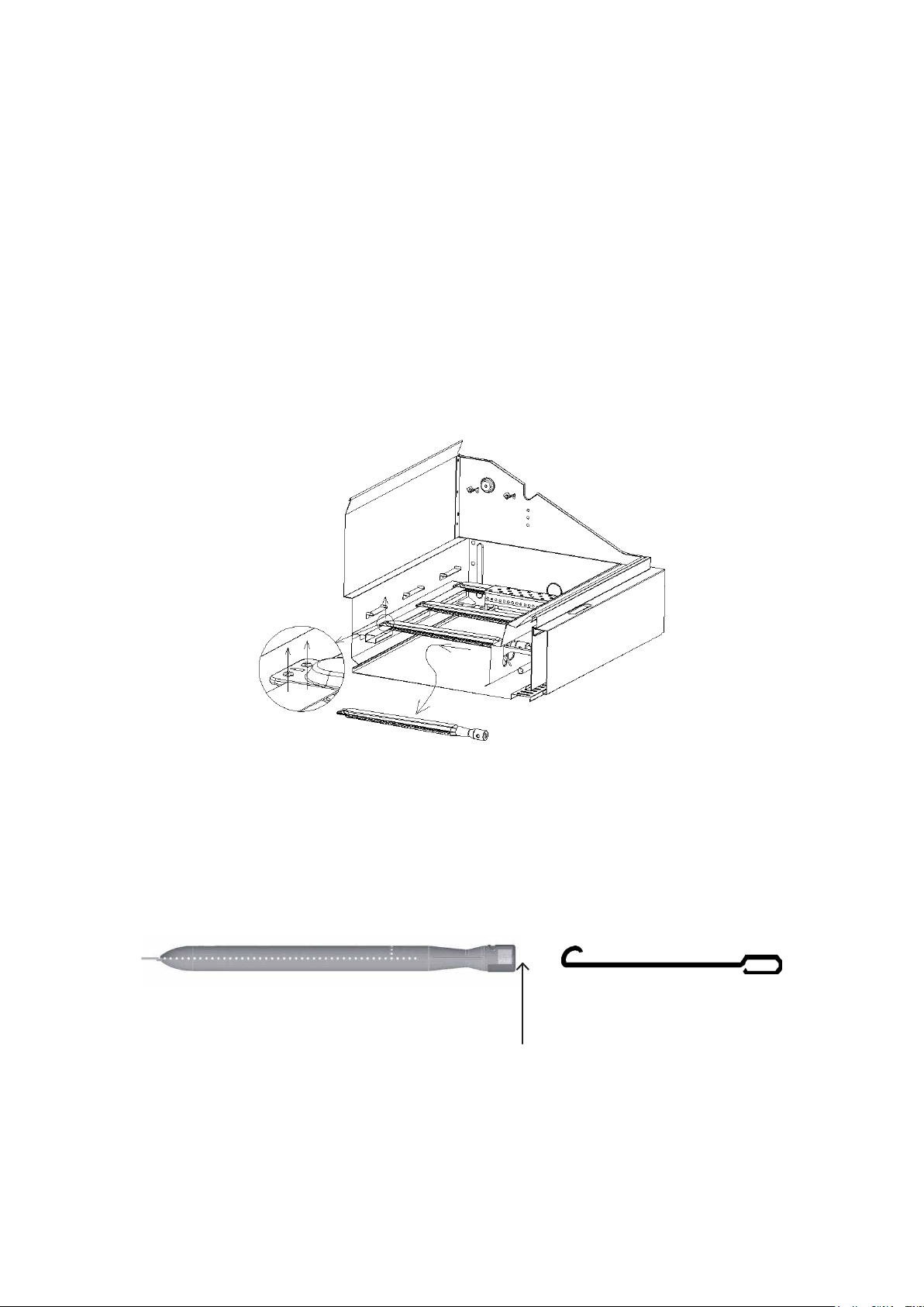
BURNER MAINTENANCE
BBUURRNNEERR MMAAIINNTTEENNAANNCCEE
To reduce the chance of “ FLASH-BACK’ the procedure below should be followed at least once a
month in late summer or early autumn when spiders are most active or when your BBQ has not
been used for a period of time.
1. Turn all burners’ valves to the full OFF position.
2. Turn the LPG cylinder valve (clockwise) to the full OFF position.
3. Detach the regulator assembly from the LPG cylinder.
4. Remove the warming rack, cast iron grill, hotplate and drip tray from your grill.
5. Remove all burners from the bottom of the grill by unscrewing the screw at the end of the
burner using a philips head screwdriver.
6. Carefully lift each burner up and away from the gas valve orifice.
To reduce the chance of “ FLASH-BACK’ the procedure below should be followed
at least once a month in late summer or early autumn when spiders are most
active or when your BBQ has not been used for a period of time. The procedure
is as follows:
1.
Turn all burners’ valves to the full OFF position.
2.
Turn the LPG cylinder valve (clockwise) to the full OFF position.
3.
Detach the regulator assembly from the LPG cylinder.
4.
Remove the warming rack, cast iron grill, hotplate and drip tray from your
grill.
5.
Remove all burners from the bottom of the grill by unscrewing the screw at
the end of the burner using a phillips head screwdriver.
6.
Carefully lift each burner up and away from the gas valve orifice, as seen
below.
7.
To clean the inside of the removed burner, multiple methods can be used,
such as:
a. Bending a stiff wire (such as a coat hanger) into a hook (seen below)
b. Using a bottle brush with a flexible handle
c. Using an air hose
BURNER WIRE HOOK
Insertion point
8.
Use a wire brush to clean the entire outer surface of each burner until free
of food residue, and dirt, as well as using a thin object to unclog ports
9.
Inspect each burner after installation, check to ensure that the gas valve
orifices are correctly placed inside the end of the burner tubes.
MATADOR INSTRUCTION MANUAL 45
Page 46
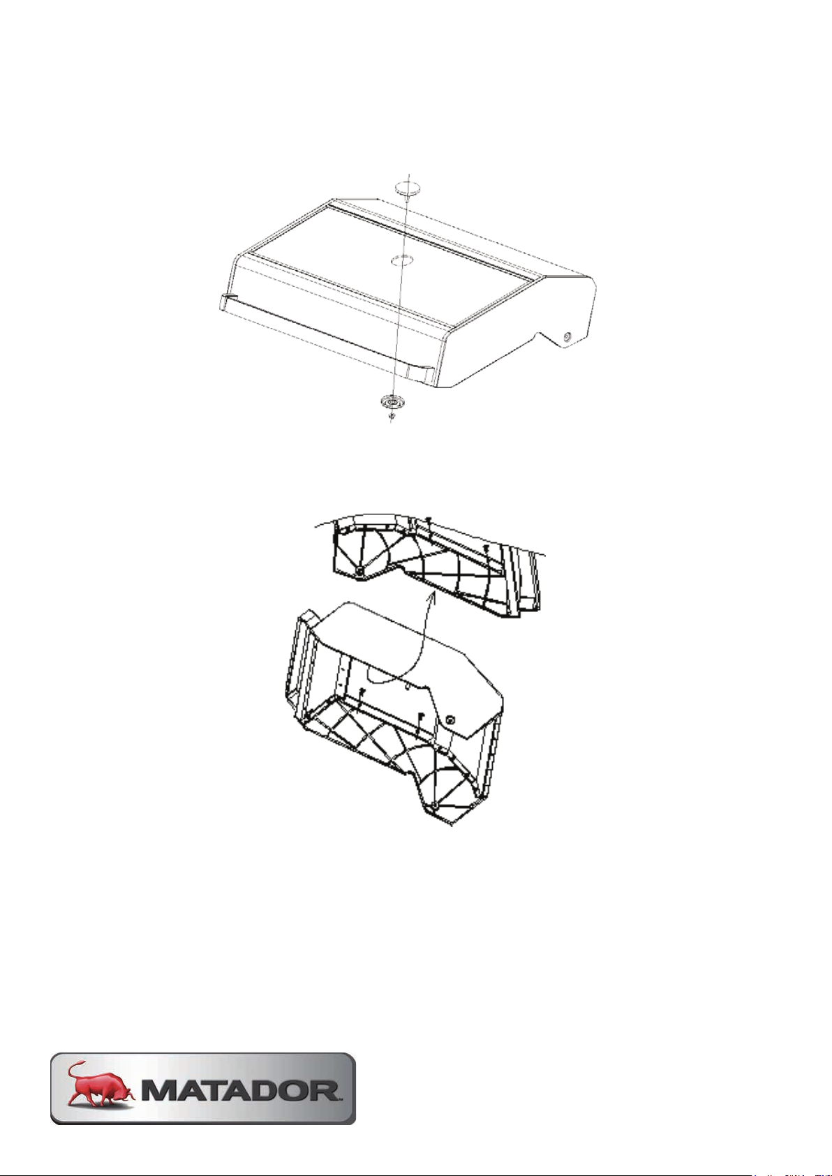
GLASS HOOD REPLACEMENT
Always wear gloves during replacement of the hood glass. The following steps
outline the procedure to replace the glass hood.
1.2.Remove the Temperature Gauge.
Disassemble the four M5 screws on the side of the unit
Page 47
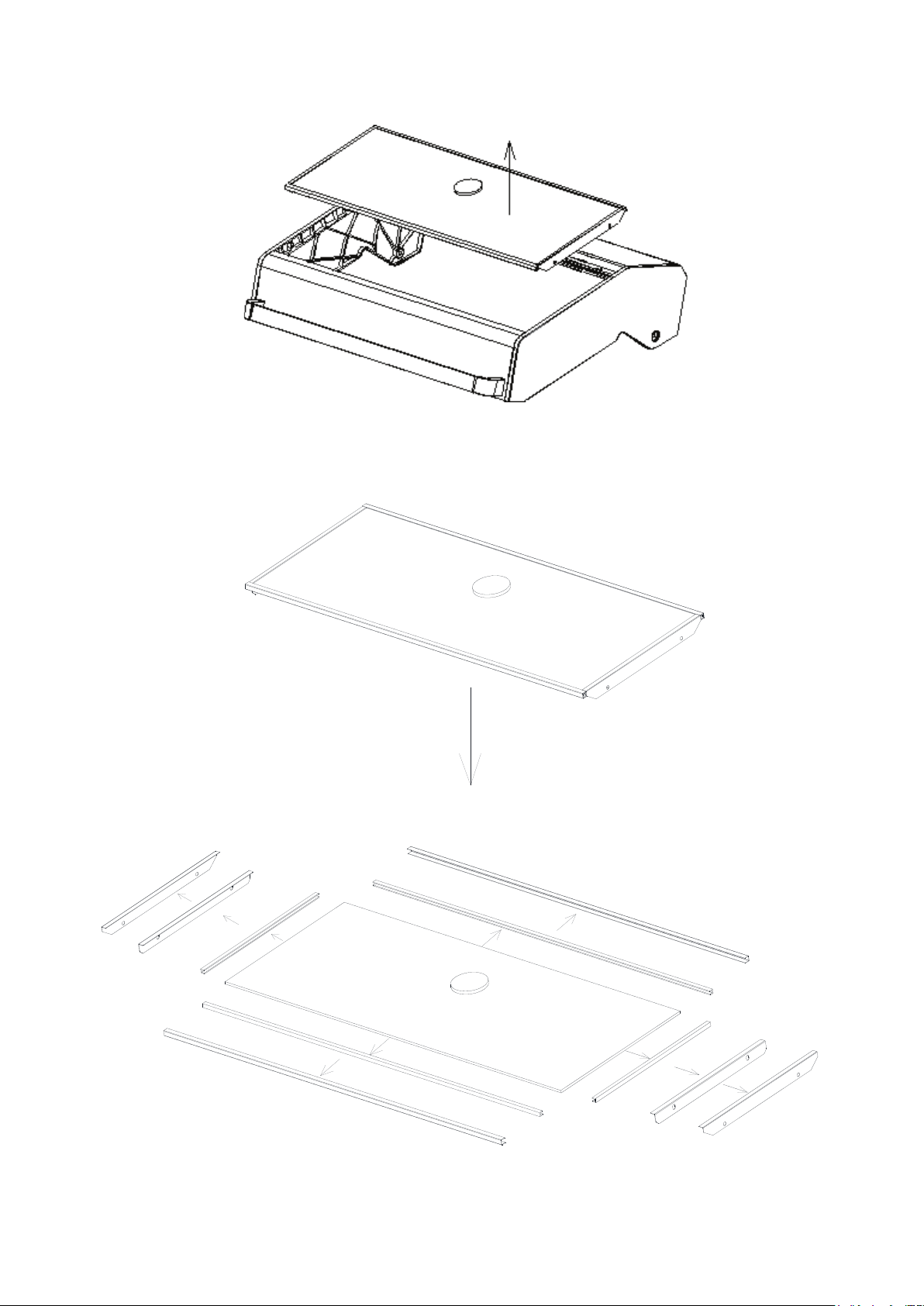
Carefully remove the glass.
3.
According to the arrow directions, remove all the parts from the glass as shown.
4.
MATADOR INSTRUCTION MANUAL 47
Page 48
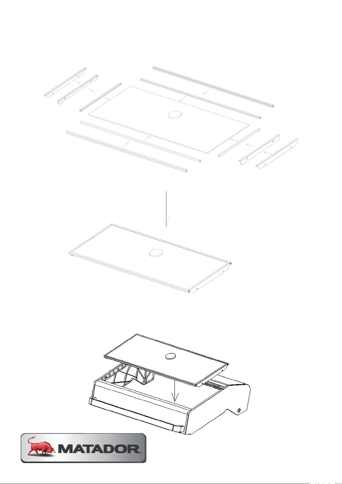
According to the arrow directions, assemble all the parts onto the replacement
5.
glass as shown.
Place the new glass assembly back onto the hood.
6.
Page 49
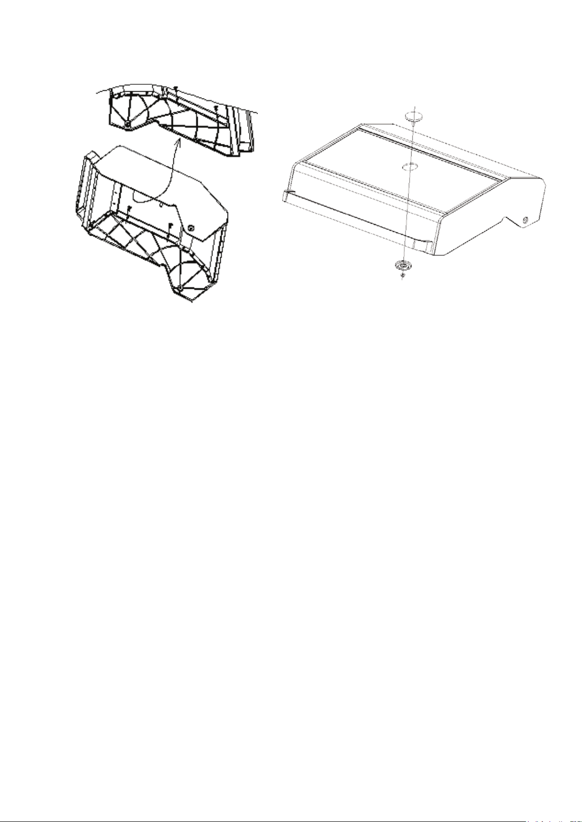
Assemble the side panels on the hood by fastening the four M5 screws as
7.
shown. Fit the temperature gauge on the glass.
The process is now complete. Check to ensure that the glass is sitting correctly on
the hood and that it is not loose.
HANDY BBQ TIPS
Ensure your BBQ is level before use so excess fat and oil can freely flow to the oil
cup in the front of the BBQ.
If food debris falls into the valleys of the cooking grill and prevents flow to the oil
cup, use the supplied Scraper Tool to quickly clear the valleys.
Preheat the grill before cooking for perfect sear marks every time.
-
Always keep a spare LPG cylinder filled and ready to go but never store the spare
cylinder near the BBQ.
Use BBQ wipes to wipe down the shiny black ceramic coated panels inside the
BBQ before cooking. The Matte black panels inside the BBQ are Pyrolytic self-
cleaning panels and they don’t require wiping.
Always keep the solid plate on the right, directly above the smoker/flavour tray to
ensure the smoker/flavor tray is always free of fat and grease residue.
MATADOR INSTRUCTION MANUAL 49
Page 50

GENERAL CARE AND MAINTENANCE INFO
Note: Remember to turn off and disconnect the gas before any maintenance is
carried out.
If your BBQ uses a flexible hose to connect to the gas cylinder, check the rubber
O-ring on the regulator end of the hose assembly at least once a year. If it appears
worn or cracked, have it replaced. Only use the hose supplied by the manufacturer.
We recommend having your BBQ checked by an authorised service agent every
5 years. This is to ensure there are no leaks and that all components are still
functioning correctly.
Keep the outdoor gas BBQ area clear and free from combustible materials, petrol,
and other flammable vapours or liquids.
Make sure there is no obstruction surrounding the BBQ, which may block the flow
of combustion and ventilation air.
To maintain the surface of your hotplate and grill plate, it is recommended to
periodically wash cooking surfaces with a mild soap and warm water solution.
Afterwards keep the hotplate and grill plate oiled and covered with the hood when
not in use. A BBQ cover (not included) is also recommended to cover your BBQ
and maintain and protect from all weather conditions.
Regularly change the sand / fat absorption granules in the drip tray.
-
Page 51

SPECIFICATIONS
REGULATOR & HOSE ASSEMBLY: 2.75kPa, POL type regulator and 8mm ID, Class
A hose 3/8SAE Female outlet. AGA approved.
Burner Configuration Table - Propane
BURNERS
NOMINAL GAS
CONSUMPTION
BBQ 15 MJ/h (per burner) 2.75 kPa 1.1mm
Side 15 MJ/h 2.75 kPa 1.1mm
Burner Configuration Table - Universal LPG
NOMINAL GAS
BURNERS
CONSUMPTION
BBQ 15 MJ/h (per burner) 2.75 kPa 1.07mm
Side 15 MJ/h 2.75 kPa 1.1mm
Burner Configuration Table - Natural Gas
TEST POINT
INJECTOR SIZE
PRESSURE
TEST POINT
INJECTOR SIZE
PRESSURE
BURNERS
NOMINAL GAS
CONSUMPTION
BBQ 15 MJ/h (per burner) 1.00 kPa 1.8mm
Side 15 MJ/h 1.00 kPa 1.8mm
Tap Specifications
WATERMARK LICENSE NUMBER WM-022545
WELS REGISTRATION NUMBER T30270
LICENSE NUMBER 1547
NOMINAL FLOW RATE 4.47 LPM
TEST POINT
INJECTOR SIZE
PRESSURE
WATER EFFICIENCY STAR RATING 6
MATADOR INSTRUCTION MANUAL 51
Page 52

CONNECTING TO
NATURAL GAS
This BBQ has been configured for use with LPG from a gas cylinder. If you want to
connect this BBQ to a permanent Natural Gas supply, the following steps must be
undertaken.
Contact a licensed plumber or gas fitter and arrange a quote to convert this BBQ
1.
to Natural Gas, install any pipework necessary to bring a natural gas supply to
the installation area and commission the BBQ. All works must be made by a
licensed plumber or gas fitter in accordance with AS5601.1.
Contact Pacific Gas & Heating Pty Ltd directly on Tel: 1300 793978 or email
2.
[email protected] to order the gas conversion kit specific to your model
and supply the name and license number of your chosen gas fitter.
Obtain a certificate of compliance from your licensed gas fitter after installation
3.
is complete.
Natural Gas Conversion Procedure
Gas conversion must be conducted by a licensed plumber or gas fitter only.
Remove the main BBQ Burners.
1.
Remove LPG injectors from all the main burner valves and replace with Natural
2.
Gas Injectors. The natural gas injector size is 1.8mm on the main burners.
Install BBQ Burners.
3.
Set the side burner aeration shutter to 4mm open.
4.
Remove the side burner valve and replace it with the side burner valve for
5.
Natural Gas. Replace the side burner injector with the 1.8mm side burner
injector for Natural Gas.
Remove 2.75kPa LPG hose and regulator assembly and replace with the
6.
stainless steel braided hose and adapter fitting to ½”BSP, and the ½”BSP
Natural gas regulator with 1.0kPa operating pressure.
Page 53

Apply the Natural Gas type label over the Propane label.
7.
Permanently fix the BBQ to the floor in the installed position using the supplied
8.
fixing bracket, which slots into the LPG Cylinder hole on freestanding BBQs.
This ensures the BBQ cannot move and strain the gas supply lines.
Leak test all connections.
9.
Before leaving, test the operation of all burners on high and low to complete the
10.
commissioning process. This involves removal of the knobs to access the screw
adjustable low flame by pass to set a stable low flame.
Instruct the consumer on correct use of the BBQ and the location of the gas
11.
supply isolation valve which shall be closed after each use.
If the BBQ is supplied with a duplicate data label, apply this label in the
12.
immediate vicinity of the BBQ in an easily accessible area.
MATADOR INSTRUCTION MANUAL 53
Page 54

PRODUCT WARRANTY
Thank you for purchasing one of our quality MATADOR products. Your MATADOR
product is covered against defects for a period of 5 years for parts and labour,
repair or replacement. This warranty excludes surface rust and damage caused by
abuse or neglect.
This warranty in Australia is given by Pacific Gas &
Heating Pty Ltd,
Tel: 1300 793978
Email: [email protected]
The warranty in New Zealand is given by Bunnings NZ
Ltd, PO BOX 14436, Panmure, Auckland, 1741.
Tel: 09-9780000 Fax: 09-9782222
Email: [email protected]
Any claim under this warranty must be made within 5
years of the date of purchase of the product. Proof of
purchase must be presented.
Goods presented for repair may be replaced by
refurbished goods of the same type rather than being
repaired. Refurbished parts may be used to repair the
may have under law: our goods come with guarantees
which cannot be excluded under the Australian
Consumer Law. You are entitled to replacement or
refund for a major failure and to compensation for other
reasonably foreseeable loss or damage. You are also
entitled to have the goods repaired or replaced if the
goods fail to be acceptable quality and the failure does
not amount to a major failure.
FOR NEW ZEALAND CUSTOMERS
To make a claim under the warranty, take the product
(with proof of purchase) to any Bunnings store (See
www.bunnings.co.nz for store locations). This warranty
is provided in addition to other rights and remedies you
may have under law: our goods come with guarantees
which cannot be excluded under the Consumer
Guarantees Act 1993(NZ). You are entitle to replacement
goods.
FOR AUSTRALIAN CUSTOMERS
To make a claim under the warranty please contact
the store where the product was purchased or contact
Pacific Gas & Heating Pty Ltd directly.
CONDITIONS OF THE WARRANTY
The warranty covers domestic use only and does not
apply to commercial applications. You may submit
details and proof to our store for consideration.
The warranty covers manufacture defects in materials,
workmanship and finish under normal use. This warranty
is provided in addition to other rights and remedies you
or refund for a major failure and to compensation for
other reasonably foreseeable loss or damage. You are
also entitled to have the goods repaired or replaced if
the goods fail to be of acceptable quality and the failure
does not amount to a major failure.
Goods presented for repair may be replaced by
refurbished goods of the same type rather than being
repaired. Refurbished parts may be used to repair the
goods.
The warranty excludes damage resulting from product
misuse or product neglect.
The warranty covers domestic use only and does not
apply to commercial applications.
Page 55

PRODUCT WARRANTY
Please thoroughly read conditions of warranty.
-
The appliance must be operated and maintained in
accordance with the instructions supplied in the
operating manual.
-
Any repair does not extend the warranty period.
-
Any parts other than original Matador
parts will void this warranty.
INSTALLATION CONDITIONS
All installations must conform to the applicable Electrical
and Building standards as laid down by the local
codes or state or region.
WHAT IS NOT COVERED IN THE WARRANTY
Removal or re-installation costs. This warranty does
-
not cover costs for transit nor in home service.
Lack of maintenance, abuse, neglect, misuse,
-
accidental or improper installation of this appliance.
Scratches, dents, corrosion or discolouration caused
-
by heat, abrasive chemical cleaners or chipping.
Corrosion or damage caused by exposure to the
-
elements such as insects, weather or hail.
RECORD THE FOLLOWING INFORMATION
Attach a copy of the purchase receipt here:
Date of purchase ………………………………..
Purchase from ………………………………..
Location ………………………………..
Model no. & name ………………………………..
Date of manufacture ………………………………..
Receipt number ………………………………..
FOR TECHNICAL ASSISTANCE
FOR AUSTRALIAN CUSTOMERS
If you experience any technical issues with your
MATADOR product, in the first instance review the
instruction manual or call the warranty service agent
below.
Cleaning and wear and tear; service calls of this
-
nature are chargeable. Commercial use of the
product.
Unauthorised repairs or modifications during the
-
warranty period.
Consumable items, example – heating
-
elements.
FOR NEW ZEALAND CUSTOMERS
If you experience any technical issues with your
MATADOR product, in the first instance review
the instruction manual or call your local Bunnings
Warehouse.
WARRANTY CLAIMS
FOR AUSTRALIAN CUSTOMERS
Please contact Pacific Gas & Heating Pty Ltd,
Tel: 1300 793978.
Email: [email protected]
FOR NEW ZEALAND CUSTOMERS
Please contact the store where the product was
purchased.
MATADOR INSTRUCTION MANUAL 55
Page 56

Visit www.matadorbbqs.com.au
For technical and warranty support call
1300 793 978 (Aus)
09-9780 000 (NZ)
Your purchase receipt will be required for warranty claims.
For spare parts contact Pacific Gas & Heating Pty Ltd.
 Loading...